EP3853603B1 - Device for measuring water content - Google Patents
Device for measuring water content Download PDFInfo
- Publication number
- EP3853603B1 EP3853603B1 EP19766268.7A EP19766268A EP3853603B1 EP 3853603 B1 EP3853603 B1 EP 3853603B1 EP 19766268 A EP19766268 A EP 19766268A EP 3853603 B1 EP3853603 B1 EP 3853603B1
- Authority
- EP
- European Patent Office
- Prior art keywords
- measuring device
- water
- implemented
- transducing element
- gas
- Prior art date
- Legal status (The legal status is an assumption and is not a legal conclusion. Google has not performed a legal analysis and makes no representation as to the accuracy of the status listed.)
- Active
Links
Images


Classifications
-
- G—PHYSICS
- G01—MEASURING; TESTING
- G01N—INVESTIGATING OR ANALYSING MATERIALS BY DETERMINING THEIR CHEMICAL OR PHYSICAL PROPERTIES
- G01N33/00—Investigating or analysing materials by specific methods not covered by groups G01N1/00 - G01N31/00
- G01N33/0004—Gaseous mixtures, e.g. polluted air
- G01N33/0009—General constructional details of gas analysers, e.g. portable test equipment
- G01N33/0011—Sample conditioning
- G01N33/0013—Sample conditioning by a chemical reaction
-
- G—PHYSICS
- G01—MEASURING; TESTING
- G01N—INVESTIGATING OR ANALYSING MATERIALS BY DETERMINING THEIR CHEMICAL OR PHYSICAL PROPERTIES
- G01N27/00—Investigating or analysing materials by the use of electric, electrochemical, or magnetic means
- G01N27/02—Investigating or analysing materials by the use of electric, electrochemical, or magnetic means by investigating impedance
- G01N27/22—Investigating or analysing materials by the use of electric, electrochemical, or magnetic means by investigating impedance by investigating capacitance
- G01N27/223—Investigating or analysing materials by the use of electric, electrochemical, or magnetic means by investigating impedance by investigating capacitance for determining moisture content, e.g. humidity
-
- A—HUMAN NECESSITIES
- A61—MEDICAL OR VETERINARY SCIENCE; HYGIENE
- A61B—DIAGNOSIS; SURGERY; IDENTIFICATION
- A61B5/00—Measuring for diagnostic purposes; Identification of persons
- A61B5/145—Measuring characteristics of blood in vivo, e.g. gas concentration or pH-value ; Measuring characteristics of body fluids or tissues, e.g. interstitial fluid or cerebral tissue
- A61B5/1468—Measuring characteristics of blood in vivo, e.g. gas concentration or pH-value ; Measuring characteristics of body fluids or tissues, e.g. interstitial fluid or cerebral tissue using chemical or electrochemical methods, e.g. by polarographic means
- A61B5/1477—Measuring characteristics of blood in vivo, e.g. gas concentration or pH-value ; Measuring characteristics of body fluids or tissues, e.g. interstitial fluid or cerebral tissue using chemical or electrochemical methods, e.g. by polarographic means non-invasive
-
- G—PHYSICS
- G01—MEASURING; TESTING
- G01L—MEASURING FORCE, STRESS, TORQUE, WORK, MECHANICAL POWER, MECHANICAL EFFICIENCY, OR FLUID PRESSURE
- G01L13/00—Devices or apparatus for measuring differences of two or more fluid pressure values
-
- G—PHYSICS
- G01—MEASURING; TESTING
- G01N—INVESTIGATING OR ANALYSING MATERIALS BY DETERMINING THEIR CHEMICAL OR PHYSICAL PROPERTIES
- G01N27/00—Investigating or analysing materials by the use of electric, electrochemical, or magnetic means
- G01N27/26—Investigating or analysing materials by the use of electric, electrochemical, or magnetic means by investigating electrochemical variables; by using electrolysis or electrophoresis
- G01N27/403—Cells and electrode assemblies
- G01N27/404—Cells with anode, cathode and cell electrolyte on the same side of a permeable membrane which separates them from the sample fluid, e.g. Clark-type oxygen sensors
- G01N27/4045—Cells with anode, cathode and cell electrolyte on the same side of a permeable membrane which separates them from the sample fluid, e.g. Clark-type oxygen sensors for gases other than oxygen
-
- G—PHYSICS
- G01—MEASURING; TESTING
- G01N—INVESTIGATING OR ANALYSING MATERIALS BY DETERMINING THEIR CHEMICAL OR PHYSICAL PROPERTIES
- G01N33/00—Investigating or analysing materials by specific methods not covered by groups G01N1/00 - G01N31/00
- G01N33/48—Biological material, e.g. blood, urine; Haemocytometers
- G01N33/483—Physical analysis of biological material
- G01N33/487—Physical analysis of biological material of liquid biological material
- G01N33/48707—Physical analysis of biological material of liquid biological material by electrical means
-
- G—PHYSICS
- G01—MEASURING; TESTING
- G01P—MEASURING LINEAR OR ANGULAR SPEED, ACCELERATION, DECELERATION, OR SHOCK; INDICATING PRESENCE, ABSENCE, OR DIRECTION, OF MOVEMENT
- G01P5/00—Measuring speed of fluids, e.g. of air stream; Measuring speed of bodies relative to fluids, e.g. of ship, of aircraft
- G01P5/02—Measuring speed of fluids, e.g. of air stream; Measuring speed of bodies relative to fluids, e.g. of ship, of aircraft by measuring forces exerted by the fluid on solid bodies, e.g. anemometer
-
- A—HUMAN NECESSITIES
- A61—MEDICAL OR VETERINARY SCIENCE; HYGIENE
- A61B—DIAGNOSIS; SURGERY; IDENTIFICATION
- A61B5/00—Measuring for diagnostic purposes; Identification of persons
- A61B5/145—Measuring characteristics of blood in vivo, e.g. gas concentration or pH-value ; Measuring characteristics of body fluids or tissues, e.g. interstitial fluid or cerebral tissue
- A61B5/14507—Measuring characteristics of blood in vivo, e.g. gas concentration or pH-value ; Measuring characteristics of body fluids or tissues, e.g. interstitial fluid or cerebral tissue specially adapted for measuring characteristics of body fluids other than blood
-
- A—HUMAN NECESSITIES
- A61—MEDICAL OR VETERINARY SCIENCE; HYGIENE
- A61B—DIAGNOSIS; SURGERY; IDENTIFICATION
- A61B5/00—Measuring for diagnostic purposes; Identification of persons
- A61B5/145—Measuring characteristics of blood in vivo, e.g. gas concentration or pH-value ; Measuring characteristics of body fluids or tissues, e.g. interstitial fluid or cerebral tissue
- A61B5/14507—Measuring characteristics of blood in vivo, e.g. gas concentration or pH-value ; Measuring characteristics of body fluids or tissues, e.g. interstitial fluid or cerebral tissue specially adapted for measuring characteristics of body fluids other than blood
- A61B5/14517—Measuring characteristics of blood in vivo, e.g. gas concentration or pH-value ; Measuring characteristics of body fluids or tissues, e.g. interstitial fluid or cerebral tissue specially adapted for measuring characteristics of body fluids other than blood for sweat
-
- A—HUMAN NECESSITIES
- A61—MEDICAL OR VETERINARY SCIENCE; HYGIENE
- A61B—DIAGNOSIS; SURGERY; IDENTIFICATION
- A61B5/00—Measuring for diagnostic purposes; Identification of persons
- A61B5/145—Measuring characteristics of blood in vivo, e.g. gas concentration or pH-value ; Measuring characteristics of body fluids or tissues, e.g. interstitial fluid or cerebral tissue
- A61B5/1468—Measuring characteristics of blood in vivo, e.g. gas concentration or pH-value ; Measuring characteristics of body fluids or tissues, e.g. interstitial fluid or cerebral tissue using chemical or electrochemical methods, e.g. by polarographic means
-
- A—HUMAN NECESSITIES
- A61—MEDICAL OR VETERINARY SCIENCE; HYGIENE
- A61B—DIAGNOSIS; SURGERY; IDENTIFICATION
- A61B5/00—Measuring for diagnostic purposes; Identification of persons
- A61B5/42—Detecting, measuring or recording for evaluating the gastrointestinal, the endocrine or the exocrine systems
- A61B5/4261—Evaluating exocrine secretion production
- A61B5/4266—Evaluating exocrine secretion production sweat secretion
-
- G—PHYSICS
- G01—MEASURING; TESTING
- G01N—INVESTIGATING OR ANALYSING MATERIALS BY DETERMINING THEIR CHEMICAL OR PHYSICAL PROPERTIES
- G01N33/00—Investigating or analysing materials by specific methods not covered by groups G01N1/00 - G01N31/00
- G01N33/0004—Gaseous mixtures, e.g. polluted air
- G01N33/0009—General constructional details of gas analysers, e.g. portable test equipment
- G01N33/0027—General constructional details of gas analysers, e.g. portable test equipment concerning the detector
- G01N33/0036—General constructional details of gas analysers, e.g. portable test equipment concerning the detector specially adapted to detect a particular component
- G01N33/005—H2
Definitions
- Thermal mass-flow meters also called thermal anenometers
- Thermal anenometers are simpler to employ. However, they are limited to a defined continuum of flow of fluid having a constant and well-known density and heat capacitance within the volume stream passing the sensor. Thermal anenometers are therefore incapable of measuring water flow in, for example, aqueous solutions of unknown composition exhibiting unknown thermo-physical parameters.
- CRHSGC high sensitivity hydrogen gas sensor
- a special purge installation was designed to clean the system with dried and purified liquid nitrogen.
- Micro-traces of water in gases first were introduced into the reactor column.
- the column was prepared by filling with a mixture of lithium and aluminium hydride (LiAIH4) and glass fibre in a vacuum box, where the water present reacted with LiAIH4 at about 60 °C.
- Hydrogen was released and determined by the hydrogen gas sensor, which was calibrated by a series of standard micro-trace hydrogen mixture gases.
- the experimental results showed that this method can be used to determine micro-traces of water in gases quickly, accurately and at a low cost. Only about 2-5 litresof sample were needed during each analysis. The method developed does not have the shortcoming of direct determination of micro-traces of water in gases that is caused by the absence of appropriate traceable calibration gases.
- JP 2018-79298 A discloses skin moisture content measuring devices.
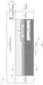
- FIG. 1 is a schematic, cross-sectional side-view of a measurement device 1 and includes two primary elements; a reactor 2 that directly or indirectly engages with and/or is in fluid communication with transducing element 8, according to the invention.
- Reactor 2 includes, for example, a (e.g., polymeric) housing 3 that may at least partially encase a hydrophilic porous filter 4 for capturing moisture and filtering impurities, a gas donor 6 characterized by its ability to generate (e.g., hydrogen) gas upon reaction with water, and a hydrophobic filter membrane 5 operative to capture unreacted water and other reactants.
- Transducing element 8 is operative to transduce the gas into an electrical signal 10 and can be implemented in various configurations as will be further discussed.
- hydrophilic porous filter 4 can be disposed such to be in fluid communication with a fluid source 10.
- gas donor 6 may be disposed between hydrophilic porous filter 4 and hydrophobic filter membrane 5.
- hydrophobic filter membrane 5 may be disposed between gas donor 6 and transducing element 8.
- hydrophilic porous filter 4, hydrophobic filter membrane 5, gas donor 6 and/or transducing element 8 may be disposed in a layered manner.
- housing 3 may extend laterally from an upper surface 5A of hydrophobic filter membrane 5 to a lower surface 4B of hydrophilic porous filter 4. Housing 3 may therefore laterally encase hydrophilic porous membrane 4, gas donor 6 and hydrophobic filter membrane 5.
- transducing element 8 may extend over the upper surface 5A of hydrophobic filter membrane 5 and the upper surface or edge 3A of housing 3.
- the upper surfaces 3A and 5A may be flush.
- the upper surfaces 3A and 5A may not be flush.
- transducing element 8 may be sized such to not extend over the later edges of hydrophobic filter membrane 5.
- housing 3 may be arranged to laterally extend over the lateral edges of transducing element 8.
- the lower surface 4B of hydrophilic porous filter 4 is exposed to allow for the continuous measurement of water content in liquid discharged by the skin of a living mammalian.
- measurement device 1 may comprise a fastener for allowing operably (and optionally, removably) coupling measurement device 1 with an animal body such to allow for the measurement of water content contained in bodily fluid discharged from the animal body.
- the fastener may include, for example, an adhesive, staple, tack, suture, and/or the like.
- measurement device 1 is configured as a patch-like structure.
- measurement device 1 is configured to be operably engaged with a skin surface portion of an animal body.
- Hydrophilic porous filter 4 provides a constant flow resistance to both liquid and gas states in the above-noted flow regime, and the hydrophilic properties do not hinder passage or facilitate passage of liquid water at the low pressures that may be associated with low flow rate regimes towards gas donor 6.
- the hydrophilic properties of porous filter 4 may facilitate the passage of water-containing liquid from fluid source 10 towards gas donor 6.
- Filter 4 may be made, for example, of glass, ceramic, metal, and/or cellulose and may, for example, have a pore size of 450 nm enabling passage of liquid and vapor while filtering particles or salt compounds.
- Hydrophilic porous filter 4 is implemented as Anodic Aluminum Oxide or Anodic Titanium Oxide with a pore size of, e.g., 5-500nm.
- gas donor 6 is disposed at the downstream side of filter 4 to enable reaction with filtered water vapor conveyed by pressure exerted by the water source through primary porous filter 4.
- the liquid water is also conveyed through via capillary action from the outside to the inside of upstream reactor 2.
- CaH 2 is employed as the gas donor.
- Alternative donors of hydrogen include, for example, metal-hydrides such as MgH 2 , NaAlH 4 , LiAlH 4 , LiH, LiBH 2 , LiBH4, non-metal hydrides, and/or some carbohydrates.
- the gas donor can act as a battery substitute and may define the upper limit of the cumulative electrical power that can be generated.
- Hydrophobic filter membrane 5 is implemented as a barrier to enclose the CaH 2 , H 2 O and Ca(OH) 2 and prevent them from entering the downstream fuel cell, in a certain embodiment.
- filter membrane 5 is implemented as combination cellulose/polyester cloth.
- Transducing element 8 translates the gas into an electrical signal by any of a variety of transducing element embodiments, as will be now discussed.
- the measurement device 1 may be configured such that hydrogen gas generated thereby is released into the environment. In this way, hydrogen gas can be continuously generated in response to (e.g., continuously) subjecting hydrophyilic porous filter 4 with (e.g., flowing) media that may contain water.
- FIGS. 2A-2F are schematic, cross-sectional side-views of various embodiments of transducing element 8.
- FIG. 2A depicts an embodiment of transducing element 8 implemented as a proton-exchange membrane (PEM) fuel cell in which hydrogen contacting a downstream gas diffusion electrode (GDE) 8C is oxidized and the electrons exit the cell on the anode side 11 through an electrical conductor. The resulting cations traverse PEM 8B.
- GDE 8D gas diffusion electrode
- the hydrogen ions recombine with electrons and form water through reaction with oxygen.
- PEM 8B is implemented as Nafion.
- FIG. 2B depicts an embodiment of transducing element 8 employing a polymer stack of the PEM fuel cells.
- FIG. 2C depicts an embodiment of transducing element 8 that employs a heating filament 18 cooled by the flow of gas. As shown, at least some of the gas is directed over a resistance heated wire 18. The resulting change in resistance or temperature distribution profile is measured by circuitry 20 and output, e.g., via leads 16 and/or a wireless transmitter.
- circuitry 20 e.g., via leads 16 and/or a wireless transmitter.
- fluid media e.g., aqueous solution
- fluid media may be characterized by its composition-dependent density and heat capacity.
- FIG. 2D depicts an embodiment of transducing element 8 that employs a porous material 19 whose dielectric constant changes as it fills with gas.
- the resulting change in capacitance is processed by circuitry 21 and outputs a signal via leads 16 and/or a wireless transmitter.
- Zeolite is an example of a such a porous material.
- FIG. 2E depicts an embodiment of transducing element 8 that employs a differential pressure sensor to transduce gas pressure into an electrical signal. As shown, a differential pressure is created as gas passes through orifice 17 and is transduced into an electric signal by circuitry 22, and signal output, e.g., via leads 16 and/or a wireless transmitter.
- FIG. 2F depicts an embodiment of transducing element 8 that employs a cantilever or stretchable membrane configured to deflect responsively to the local pressure field generated by the gas-stream.
- gas applies a pressure to flexible element 24 and the resulting deformation is quantified through an electromechanical transducer or circuitry 23, and a signal output, e.g., via leads 16 and/or a wireless transmitter.
- FIG. 3 depicts an embodiment of measurement device 1 applied as a sweat gauge mounted to sweating skin 13.
- Water and other sweat constituents are captured by primary hydrophilic porous filter 4, the non-aquatic constituents are filtered out, and the remaining water content conveyed downstream where it contacts the hydrogen donor CaH 2 6 disposed at the downstream edge of primary filter 4. There the CaH 2 reacts with water to form a stoichiometric volume of hydrogen that creates a pressure gradient driving the hydrogen through secondary filter 5.
- Water filter 5 filters unreacted water, CaH 2 and Ca(OH) 2 and has a low flow resistance relative to primary filter 4. This filtering may become increasingly significant in protecting transducing element 8 as reaction efficiency diminishes with time and the quantity of unreacted water increases.
- transducing element 8 implemented in this example as a single-cell membrane electrode assembly (MEA) having a proton exchange membrane PEM 8B sandwiched between two gas diffusion electrodes GDEs 8C and 8D, as noted above.
- MEA single-cell membrane electrode assembly
- PEM 8B proton exchange membrane
- GDEs 8C and 8D gas diffusion electrodes
- Each of GDEs 8C and 8D has an electrically conductive supporting cloth enabling gas distribution and an electrode with a catalyst where the chemical reactions occur.
- the catalyst coated surfaces are in contact with PEM electrolyte 8B.
- GDE 8C hydrogen is oxidized to cations H+ and the electrons leave measurement device 1 at anode 11.
- the cations pass the solid-state electrolyte PEM 8B and the oxygen is reduced and combines with cations to produce water at cathode 12, as noted above.
- the PEM 8B is a gas selective permeable membrane resulting in a hydrogen and oxygen gradient across the membrane thickness. It acts as convey path for protons supply the GDE 8D with protons H+, while blocking oxygen and ions thereof.
- the GDE 8D in contact with the PEM promotes a high conversion rate of the protons to water.
- MEA 8A is in communication with gas distribution channel 8F to maximize hydrogen contact with to the membrane surface.
- a high conversion rate is obtained by using MEAs.
- Non-converted excess hydrogen can leave the system after passing membrane surface 8D in a certain embodiment.
- a bypass channel (not shown) directs a known, fixed fraction of hydrogen directly out of housing 3 and does not produce an electrical signal to prevent saturation of the fuel cell and facilitate miniaturization of MEA 8A.
- Measurement device 1 can be self-actuated and deactivated in accordance with stoichiometric limitation set by the amount of water available.
- the required precision measurement is achieved through the capture of sweat in static and/or any flowing state and the conversion of the sweat, based on the amount of water contained therein, into a corresponding collective electrical signal.
- the senor also generates harnessable electricity.
- Measurement device 1 may be comparatively efficient and effective for static and non-static states and have a high sensitivity down to flow rates of the less than, for example, 10uL/min. Measurement device 1 is also effective for liquid, gaseous, and vapor states over a temperature range like, for example, 5-40°C, has a fast response time of some seconds, has a slew rate of, e.g., 3-5 seconds to reach the nominal output power, and has a comparatively low cost. Its dynamic range spans, e.g., at least five orders of magnitude and is highly selective in that its capable of identifying and measuring the amount of water included in any media that may comprise, for example, aqueous solutions among a variety of other compositions.
- FIG. 4 is a flowchart of the processing steps employed by the measurement device (e.g., water sensor) and can be divided into three stages, gas generation 3100, signal generation 3200, and output 3800.
- the measurement device e.g., water sensor
- step 32 water is captured at step 32 as a liquid, gas or vapor with a hydrophilic material, as noted above.
- the water is contacted with a reactant characterized by its gas generation properties as a reaction product.
- the liberated gas is conveyed through a hydrophobic membrane 5 while filtering unreacted water and reacted CaH 2 .
- the liberated gas is transduced into an electrical signal at step 35 through any of the transducing element embodiments noted above.
- the signal is measured either as a current or a voltage in accordance with the type of transducing element employed.
- the measured signal is rendered into a quantitative measurement of the flow rate of water fluid in accordance with a given reaction conversion.
- the quantitative measurement is output at step 39, for example, to a display screen.
Landscapes
- Health & Medical Sciences (AREA)
- Life Sciences & Earth Sciences (AREA)
- Chemical & Material Sciences (AREA)
- Physics & Mathematics (AREA)
- Engineering & Computer Science (AREA)
- General Physics & Mathematics (AREA)
- Pathology (AREA)
- General Health & Medical Sciences (AREA)
- Biomedical Technology (AREA)
- Analytical Chemistry (AREA)
- Immunology (AREA)
- Chemical Kinetics & Catalysis (AREA)
- Biochemistry (AREA)
- Molecular Biology (AREA)
- Biophysics (AREA)
- Medicinal Chemistry (AREA)
- Food Science & Technology (AREA)
- Electrochemistry (AREA)
- Medical Informatics (AREA)
- Aviation & Aerospace Engineering (AREA)
- General Chemical & Material Sciences (AREA)
- Optics & Photonics (AREA)
- Heart & Thoracic Surgery (AREA)
- Hematology (AREA)
- Surgery (AREA)
- Animal Behavior & Ethology (AREA)
- Public Health (AREA)
- Veterinary Medicine (AREA)
- Urology & Nephrology (AREA)
- Combustion & Propulsion (AREA)
- Measuring Oxygen Concentration In Cells (AREA)
Description
- High-precision measurement of water content in the flow regime of
lessthan 10 microliter/minute iscrucial for many applications. Today, there are multiple state-of-the art solutions; however, each suffers from a deficiency. Many solutions require expensive, specialized equipment that are dependent on an external electrical power source and require a lab setting. Examples include, thermal massflow meter, Doppler ultrasonic flow meters, Venturi flow meters, Coriolisflow metersjust to name a few. - Thermal mass-flow meters, also called thermal anenometers, are simpler to employ. However, they are limited to a defined continuum of flow of fluid having a constant and well-known density and heat capacitance within the volume stream passing the sensor. Thermal anenometers are therefore incapable of measuring water flow in, for example, aqueous solutions of unknown composition exhibiting unknown thermo-physical parameters.
- Therefore, there is a need for a high-precision measurement device that can reliably and precisely determine the flow rate of an aqueous solution, circulating in a known environment (such as a microfluidic system), that is inexpensive, and deployable in a wide variety of settings function in the above-noted flow regime.
- ZEYI ZHOU ET ALdiscloses: "Determination of micro-traces of water in gases by a hydrogen gas sensor combined with a conversion reactor column; Determination of micro-traces of water in gases by a hydrogen gas sensor combined with aconversion reactor column", MEASUREMENT SCIENCE AND TECHNOLOGY, vol. 15, no. 10, 15 September 2004 (2004-09-15), pages2170-2174, XP020066399, ISSN: 0957-0233, DOI: 1 0.1 088/0957-0233/15/10/030, discloses: Micro-traces of water in gases have been determined by using a combination of a conversion reactor column and a high sensitivity hydrogen gas sensor (abbreviated here to CRHSGC). A special purge installation was designed to clean the system with dried and purified liquid nitrogen. Micro-traces of water in gases first were introduced into the reactor column. The column was prepared by filling with a mixture of lithium and aluminium hydride (LiAIH4) and glass fibre in a vacuum box, where the water present reacted with LiAIH4 at about 60 °C. Hydrogen was released and determined by the hydrogen gas sensor, which was calibrated by a series of standard micro-trace hydrogen mixture gases. The experimental results showed that this method can be used to determine micro-traces of water in gases quickly, accurately and at a low cost. Only about 2-5 litresof sample were needed during each analysis. The method developed does not have the shortcoming of direct determination of micro-traces of water in gases that is caused by the absence of appropriate traceable calibration gases.
-
JP 2018-79298 A - The figures illustrate generally, by way of example, but not by way of limitation, various embodiments discussed in the present document.
For simplicity and clarity of illustration, elements shown in the figures have not necessarily been drawn to scale. For example, the dimensions of some of the elements may be exaggerated relative to other elements for clarity of presentation. Furthermore, reference numerals may be repeated among the figures to indicate corresponding or analogous elements. References to previously presented elements are implied without necessarily further citing the drawing or description in which they appear. The number of elements shown in the Figures should by no means be construed as limiting and is for illustrative purposes only. The figures are listed below. -
FIG. 1 is a schematic, cross-sectional side-view of a measurement device, according to some embodiments; -
FIGS. 2A-2F are schematic, cross-sectional side-views of various embodiments of a transducing element employable in the measurement device ofFIG. 1 ; -
FIG. 3 is a schematic, cross-sectional side-view of a measurement device mounted on a body to measure the flow rate of water, for example, due to the discharge of fluid from matter (e.g., perspiration or sweat rate), according to some embodiments; and -
FIG. 4 is a flowchart of the process steps employed by the measurement device, according to some embodiments. - The following description sets forth various details to provide a thorough understanding of the invention and it should be appreciated, by those skilled in the art, that the present invention may be practiced without these specific details. Furthermore, well-known methods, procedures, and components have been omitted to highlight the present invention.
- Turning now to the figures,
FIG. 1 is a schematic, cross-sectional side-view of a measurement device 1 and includes two primary elements; areactor 2 that directly or indirectly engages with and/or is in fluid communication with transducingelement 8, according to the invention.Reactor 2 includes, for example, a (e.g., polymeric)housing 3 that may at least partially encase a hydrophilicporous filter 4 for capturing moisture and filtering impurities, agas donor 6 characterized by its ability to generate (e.g., hydrogen) gas upon reaction with water, and ahydrophobic filter membrane 5 operative to capture unreacted water and other reactants.Transducing element 8 is operative to transduce the gas into anelectrical signal 10 and can be implemented in various configurations as will be further discussed. - In some embodiments, hydrophilic
porous filter 4 can be disposed such to be in fluid communication with afluid source 10. - In some embodiments,
gas donor 6 may be disposed between hydrophilicporous filter 4 andhydrophobic filter membrane 5. In some embodiments,hydrophobic filter membrane 5 may be disposed betweengas donor 6 and transducingelement 8. Optionally, hydrophilicporous filter 4,hydrophobic filter membrane 5,gas donor 6 and/or transducingelement 8 may be disposed in a layered manner. Optionally,housing 3 may extend laterally from anupper surface 5A ofhydrophobic filter membrane 5 to alower surface 4B of hydrophilicporous filter 4.Housing 3 may therefore laterally encase hydrophilicporous membrane 4,gas donor 6 andhydrophobic filter membrane 5. In some embodiments, as exemplified inFIG. 1 , transducingelement 8 may extend over theupper surface 5A ofhydrophobic filter membrane 5 and the upper surface oredge 3A ofhousing 3. Optionally, theupper surfaces upper surfaces element 8 may be sized such to not extend over the later edges ofhydrophobic filter membrane 5. Optionally,housing 3 may be arranged to laterally extend over the lateral edges of transducingelement 8. - The
lower surface 4B of hydrophilicporous filter 4 is exposed to allow for the continuous measurement of water content in liquid discharged by the skin of a living mammalian. - In some embodiments, measurement device 1 may comprise a fastener for allowing operably (and optionally, removably) coupling measurement device 1 with an animal body such to allow for the measurement of water content contained in bodily fluid discharged from the animal body. The fastener may include, for example, an adhesive, staple, tack, suture, and/or the like.
- In accordance with the invention, measurement device 1 is configured as a patch-like structure.
- In accordance with the invention, measurement device 1 is configured to be operably engaged with a skin surface portion of an animal body.
- Hydrophilic
porous filter 4 provides a constant flow resistance to both liquid and gas states in the above-noted flow regime, and the hydrophilic properties do not hinder passage or facilitate passage of liquid water at the low pressures that may be associated with low flow rate regimes towardsgas donor 6. For example, the hydrophilic properties ofporous filter 4 may facilitate the passage of water-containing liquid fromfluid source 10 towardsgas donor 6.Filter 4 may be made, for example, of glass, ceramic, metal, and/or cellulose and may, for example, have a pore size of 450 nm enabling passage of liquid and vapor while filtering particles or salt compounds. - In another embodiment, Hydrophilic
porous filter 4 is implemented as Anodic Aluminum Oxide or Anodic Titanium Oxide with a pore size of, e.g., 5-500nm. - As shown,
gas donor 6 is disposed at the downstream side offilter 4 to enable reaction with filtered water vapor conveyed by pressure exerted by the water source through primaryporous filter 4. Incertain filters 4, the liquid water is also conveyed through via capillary action from the outside to the inside ofupstream reactor 2. - In some embodiments, CaH2 is employed as the gas donor. Alternative donors of hydrogen include, for example, metal-hydrides such as MgH2, NaAlH4, LiAlH4, LiH, LiBH2, LiBH4, non-metal hydrides, and/or some carbohydrates. The gas donor can act as a battery substitute and may define the upper limit of the cumulative electrical power that can be generated.
-
Hydrophobic filter membrane 5 is implemented as a barrier to enclose the CaH2, H2O and Ca(OH)2 and prevent them from entering the downstream fuel cell, in a certain embodiment. In another embodiment,filter membrane 5 is implemented as combination cellulose/polyester cloth. - Transducing
element 8 translates the gas into an electrical signal by any of a variety of transducing element embodiments, as will be now discussed. - The measurement device 1 may be configured such that hydrogen gas generated thereby is released into the environment. In this way, hydrogen gas can be continuously generated in response to (e.g., continuously) subjecting hydrophyilic
porous filter 4 with (e.g., flowing) media that may contain water. -
FIGS. 2A-2F are schematic, cross-sectional side-views of various embodiments of transducingelement 8. - Specifically,
FIG. 2A depicts an embodiment of transducingelement 8 implemented as a proton-exchange membrane (PEM) fuel cell in which hydrogen contacting a downstream gas diffusion electrode (GDE) 8C is oxidized and the electrons exit the cell on theanode side 11 through an electrical conductor. The resulting cations traversePEM 8B. AtGDE 8D the hydrogen ions recombine with electrons and form water through reaction with oxygen. In acertain embodiment PEM 8B is implemented as Nafion. -
FIG. 2B depicts an embodiment of transducingelement 8 employing a polymer stack of the PEM fuel cells. -
FIG. 2C depicts an embodiment of transducingelement 8 that employs aheating filament 18 cooled by the flow of gas. As shown, at least some of the gas is directed over a resistance heatedwire 18. The resulting change in resistance or temperature distribution profile is measured bycircuitry 20 and output, e.g., via leads 16 and/or a wireless transmitter. It should be appreciated that the above noted deficiencies of an anemometer are removed through conversion of any fluid media (e.g., aqueous solution) operably engaging with the device into a pure gas. It is noted that fluid media may be characterized by its composition-dependent density and heat capacity. -
FIG. 2D depicts an embodiment of transducingelement 8 that employs aporous material 19 whose dielectric constant changes as it fills with gas. The resulting change in capacitance is processed by circuitry 21 and outputs a signal via leads 16 and/or a wireless transmitter. Zeolite is an example of a such a porous material. -
FIG. 2E depicts an embodiment of transducingelement 8 that employs a differential pressure sensor to transduce gas pressure into an electrical signal. As shown, a differential pressure is created as gas passes throughorifice 17 and is transduced into an electric signal bycircuitry 22, and signal output, e.g., via leads 16 and/or a wireless transmitter. -
FIG. 2F depicts an embodiment of transducingelement 8 that employs a cantilever or stretchable membrane configured to deflect responsively to the local pressure field generated by the gas-stream. As shown, gas applies a pressure toflexible element 24 and the resulting deformation is quantified through an electromechanical transducer orcircuitry 23, and a signal output, e.g., via leads 16 and/or a wireless transmitter. -
FIG. 3 depicts an embodiment of measurement device 1 applied as a sweat gauge mounted to sweatingskin 13. - Water and other sweat constituents are captured by primary hydrophilic
porous filter 4, the non-aquatic constituents are filtered out, and the remaining water content conveyed downstream where it contacts thehydrogen donor CaH 2 6 disposed at the downstream edge ofprimary filter 4. There the CaH2 reacts with water to form a stoichiometric volume of hydrogen that creates a pressure gradient driving the hydrogen throughsecondary filter 5.Water filter 5 filters unreacted water, CaH2 and Ca(OH)2 and has a low flow resistance relative toprimary filter 4. This filtering may become increasingly significant in protectingtransducing element 8 as reaction efficiency diminishes with time and the quantity of unreacted water increases. The hydrogen continues downstream andcontacts transducing element 8 implemented in this example as a single-cell membrane electrode assembly (MEA) having a protonexchange membrane PEM 8B sandwiched between two gasdiffusion electrodes GDEs GDEs PEM electrolyte 8B. - As shown,
GDE 8C hydrogen is oxidized to cations H+ and the electrons leave measurement device 1 atanode 11. The cations pass the solid-state electrolyte PEM 8B and the oxygen is reduced and combines with cations to produce water atcathode 12, as noted above. - The
PEM 8B is a gas selective permeable membrane resulting in a hydrogen and oxygen gradient across the membrane thickness. It acts as convey path for protons supply theGDE 8D with protons H+, while blocking oxygen and ions thereof. TheGDE 8D in contact with the PEM promotes a high conversion rate of the protons to water. -
MEA 8A is in communication withgas distribution channel 8F to maximize hydrogen contact with to the membrane surface. A high conversion rate is obtained by using MEAs. Non-converted excess hydrogen can leave the system after passingmembrane surface 8D in a certain embodiment. - In another embodiment, a bypass channel (not shown) directs a known, fixed fraction of hydrogen directly out of
housing 3 and does not produce an electrical signal to prevent saturation of the fuel cell and facilitate miniaturization ofMEA 8A. Measurement device 1 can be self-actuated and deactivated in accordance with stoichiometric limitation set by the amount of water available. - As taught, the required precision measurement is achieved through the capture of sweat in static and/or any flowing state and the conversion of the sweat, based on the amount of water contained therein, into a corresponding collective electrical signal.
- Furthermore, in addition to its measuring capacity, the sensor also generates harnessable electricity.
- Measurement device 1 may be comparatively efficient and effective for static and non-static states and have a high sensitivity down to flow rates of the less than, for example, 10uL/min. Measurement device 1 is also effective for liquid, gaseous, and vapor states over a temperature range like, for example, 5-40°C, has a fast response time of some seconds, has a slew rate of, e.g., 3-5 seconds to reach the nominal output power, and has a comparatively low cost. Its dynamic range spans, e.g., at least five orders of magnitude and is highly selective in that its capable of identifying and measuring the amount of water included in any media that may comprise, for example, aqueous solutions among a variety of other compositions.
-
FIG. 4 is a flowchart of the processing steps employed by the measurement device (e.g., water sensor) and can be divided into three stages,gas generation 3100,signal generation 3200, andoutput 3800. - Specifically, in
gas generation stage 3100, water is captured atstep 32 as a liquid, gas or vapor with a hydrophilic material, as noted above. Instep 33, the water is contacted with a reactant characterized by its gas generation properties as a reaction product. Instep 34 the liberated gas is conveyed through ahydrophobic membrane 5 while filtering unreacted water and reacted CaH2. - In
stage 3200, the liberated gas is transduced into an electrical signal atstep 35 through any of the transducing element embodiments noted above. Instep 36, the signal is measured either as a current or a voltage in accordance with the type of transducing element employed. Instep 37, the measured signal is rendered into a quantitative measurement of the flow rate of water fluid in accordance with a given reaction conversion. - In the single-
step output stage 3800, the quantitative measurement is output atstep 39, for example, to a display screen.
Claims (14)
- A measuring device (1) operably engageable with a skin surface portion of a skin surface of an animal body for measuring water content in a bodily media discharged by the skin surface, the measurement device being configured as a patch-like structure, wherein the measuring device (1) is characterized by:a reactor (2) comprising a reactant gas donor (6), wherein the reactor (2) is configured to liberate a hydrogen stream having a stoichiometric equivalent to water in the media, the reactant gas donor (6) having an ability to liberate hydrogen gas upon reaction with water; anda transducing element (8) configured to transduce the hydrogen stream into an electrical signal,wherein the reactor (2) is configured such that the reactant gas donor (6) can be continuously subjected to flow of the bodily media.
- The measuring device (1) of claim 1, further comprising circuitry (20, 21, 22, 23) that is configured to determine a value related to a quantity of water fluid in accordance with the electrical signal; and an output device configured to output the quantity of the water fluid.
- The measuring device (1) of any one or more of the claims 1 to 2, wherein the reactant gas donor (6) is implemented as metallic or non-metallic hydride, wherein the metallic hydride is, for example, selected from the group consisting of MgH2, NaAIH4, LiAIH4, LiH, LiBH2, and LiBH4.
- The measuring device (1) of claim 3, wherein the metallic hydride is implemented as CaH2.
- The measuring device (1) of any one or more of claims 1 to 4, wherein the transducing element (8) is implemented as a fuel cell (8A, 8B) driven by the hydrogen stream.
- The measuring device (1) of claim 5, wherein the fuel cell (8A, 8B) includes a proton-exchange membrane (PEM).
- The measuring device (1) of any one or more of claims 1 to 6, wherein the transducing element (8) is implemented as porous dielectric (19) whose capacitance changes in accordance with a degree of permeation of the hydrogen stream, wherein the porous dielectric (19) is, for example, implemented as a zeolite.
- The measuring device (1) of any one or more of claims 1 to 7, wherein the transducing element (8) is implemented as a pressure sensor configured to generate the electric signal responsively to a differential pressure generated by the hydrogen stream.
- The measuring device (1) of any one or more of claims 1 to 8, wherein the transducing element (8) is implemented as an anemometer configured to generate the electric signal in accordance with gas flow of the hydrogen stream.
- The measuring device (1) of any one or more of claims 1 to 9, configured such that the gas donor (6) makes direct or indirect contact with an animal body for measuring the water content contained in bodily media discharged by the animal body and, wherein, the bodily media comprises, for example, sweat.
- The measuring device (1) of any one or more of the claims 1 to 10, further comprising a hydrophilic porous filter (4), wherein the gas donor (6) is disposed within and/or layered above the hydrophilic porous (4), wherein the hydrophilic porous filter (4) can be in fluid communication with the fluid source (10).
- The measuring device (1) of any one or more of the claims 1 to 11, further comprising a water filter (5) upstream of the transducing element (6) to capture unreacted water.
- The measuring device (1) of claim 12, wherein the water filter is a hydrophobic filter membrane
- The measuring device (1) of any one or more of the claims 1 to 13, further comprising a fastener for operably coupling the measuring device (1) with the animal body.
Applications Claiming Priority (2)
| Application Number | Priority Date | Filing Date | Title |
|---|---|---|---|
| EP18194729.2A EP3623808A1 (en) | 2018-09-17 | 2018-09-17 | Electrochemical sensor for the measurement of water content |
| PCT/EP2019/074784 WO2020058232A1 (en) | 2018-09-17 | 2019-09-17 | Device for measuring water content |
Publications (2)
| Publication Number | Publication Date |
|---|---|
| EP3853603A1 EP3853603A1 (en) | 2021-07-28 |
| EP3853603B1 true EP3853603B1 (en) | 2024-12-25 |
Family
ID=63642552
Family Applications (2)
| Application Number | Title | Priority Date | Filing Date |
|---|---|---|---|
| EP18194729.2A Withdrawn EP3623808A1 (en) | 2018-09-17 | 2018-09-17 | Electrochemical sensor for the measurement of water content |
| EP19766268.7A Active EP3853603B1 (en) | 2018-09-17 | 2019-09-17 | Device for measuring water content |
Family Applications Before (1)
| Application Number | Title | Priority Date | Filing Date |
|---|---|---|---|
| EP18194729.2A Withdrawn EP3623808A1 (en) | 2018-09-17 | 2018-09-17 | Electrochemical sensor for the measurement of water content |
Country Status (4)
| Country | Link |
|---|---|
| US (1) | US20220034836A1 (en) |
| EP (2) | EP3623808A1 (en) |
| CN (1) | CN113287010A (en) |
| WO (1) | WO2020058232A1 (en) |
Families Citing this family (1)
| Publication number | Priority date | Publication date | Assignee | Title |
|---|---|---|---|---|
| WO2026006253A1 (en) * | 2024-06-26 | 2026-01-02 | Energy Related Devices, Inc. | Integrated counter flow heat and mass exchangers within fuel cells |
Citations (1)
| Publication number | Priority date | Publication date | Assignee | Title |
|---|---|---|---|---|
| JP2018079298A (en) * | 2016-11-07 | 2018-05-24 | 株式会社 資生堂 | Skin moisture content measurement device, wearable device, skin moisture content measurement method, skin moisture content evaluation method, skin moisture content monitoring system, skin moisture content evaluation network system, and skin moisture content evaluation program |
Family Cites Families (7)
| Publication number | Priority date | Publication date | Assignee | Title |
|---|---|---|---|---|
| CN1958438B (en) * | 2005-10-31 | 2011-01-12 | 上海清能燃料电池技术有限公司 | Device and method for producing hydrogen |
| FR2893606B1 (en) * | 2005-11-24 | 2008-04-25 | Commissariat Energie Atomique | HYDROGEN GENERATOR AND FUEL CELL IMPLEMENTING SUCH A GENERATOR |
| US8298719B2 (en) * | 2006-11-07 | 2012-10-30 | University Of North Florida Board Of Trustees | Passive recovery of liquid water produced by fuel cells |
| CN101508422A (en) * | 2009-03-24 | 2009-08-19 | 中南大学 | Method for aluminum-lithium alloy water-splitting hydrogen production |
| WO2015047750A1 (en) * | 2013-09-26 | 2015-04-02 | 3M Innovative Properties Company | Vapor sensor suitable for detecting alcoholic residue at a skin site |
| CN105293716B (en) * | 2015-09-22 | 2017-11-03 | 中国科学院成都生物研究所 | A kind of microbiological fuel cell and its method for handling waste water |
| DE102016212948A1 (en) * | 2016-07-15 | 2017-08-24 | Continental Automotive Gmbh | Hydrogen sensor for determining a hydrogen content of a gas |
-
2018
- 2018-09-17 EP EP18194729.2A patent/EP3623808A1/en not_active Withdrawn
-
2019
- 2019-09-17 WO PCT/EP2019/074784 patent/WO2020058232A1/en not_active Ceased
- 2019-09-17 US US17/276,501 patent/US20220034836A1/en not_active Abandoned
- 2019-09-17 EP EP19766268.7A patent/EP3853603B1/en active Active
- 2019-09-17 CN CN201980071741.XA patent/CN113287010A/en active Pending
Patent Citations (1)
| Publication number | Priority date | Publication date | Assignee | Title |
|---|---|---|---|---|
| JP2018079298A (en) * | 2016-11-07 | 2018-05-24 | 株式会社 資生堂 | Skin moisture content measurement device, wearable device, skin moisture content measurement method, skin moisture content evaluation method, skin moisture content monitoring system, skin moisture content evaluation network system, and skin moisture content evaluation program |
Also Published As
| Publication number | Publication date |
|---|---|
| CN113287010A (en) | 2021-08-20 |
| EP3623808A1 (en) | 2020-03-18 |
| US20220034836A1 (en) | 2022-02-03 |
| WO2020058232A1 (en) | 2020-03-26 |
| EP3853603A1 (en) | 2021-07-28 |
Similar Documents
| Publication | Publication Date | Title |
|---|---|---|
| US6455181B1 (en) | Fuel cell system with sensor | |
| CA1287323C (en) | Apparatus and method for purifying hydrogen | |
| DE69708422T2 (en) | Fuel cell generator with control system and method for generating electricity using fuel cells | |
| US7913572B2 (en) | Integrated multi-measurement system for measuring physical properties of gas diffusion layer for polymer electrolyte fuel cell with respect to compression | |
| KR100902316B1 (en) | Physical property evaluation device to measure length, resistance, differential pressure, etc. according to pressure of gas diffusion layer used in fuel cell | |
| EP0710835A2 (en) | Apparatus for detecting carbon monoxide, organic compound, and lower alcohol, and methods of the same | |
| US6770391B2 (en) | Hydrogen sensor for fuel processors of a fuel cell | |
| US20030190508A1 (en) | Chemical reaction apparatus and power supply system | |
| WO2000045447A9 (en) | Proton conducting membrane using a solid acid | |
| US20110212376A1 (en) | Amperometric sensor | |
| US6893756B2 (en) | Lambda sensing with a fuel cell stack | |
| CN101356677A (en) | Fuel cells and fuel cell systems and electronic devices | |
| US6985082B1 (en) | Carbon monoxide sensor and method of use | |
| US9127370B2 (en) | Power-free apparatus for hydrogen generation from alcohol | |
| AU2002320440A1 (en) | Carbon monoxide sensor and method of use | |
| Gülzow et al. | Bipolar concept for alkaline fuel cells | |
| EP3623808A1 (en) | Electrochemical sensor for the measurement of water content | |
| JP2002207024A (en) | CO sensor and CO concentration measurement method | |
| JP5777503B2 (en) | Hydrogen gas sensor | |
| JP2022065582A (en) | Hydrogen gas concentration sensor for fuel cells | |
| Poulianitis et al. | Investigation of the reaction of ethanol-steam mixtures in a YSZ electrochemical reactor operated in a fuel cell mode | |
| Grot et al. | Evaluation of the humidification requirements of new proton exchange membranes for fuel cells | |
| Mohammed et al. | Parameters Affecting the Thermodynamic Efficiency of PEM Single Cell and Stack of Cells (Two Cells) | |
| Živko et al. | Analysis of individual PEM fuel cell operating parameters for design of optimal measurement and control instrumentation | |
| Reddy | The effectivness of using a non-platinum material combination for the catalyst layer of a proton exchange membrane fuel cell |
Legal Events
| Date | Code | Title | Description |
|---|---|---|---|
| STAA | Information on the status of an ep patent application or granted ep patent |
Free format text: STATUS: UNKNOWN |
|
| STAA | Information on the status of an ep patent application or granted ep patent |
Free format text: STATUS: THE INTERNATIONAL PUBLICATION HAS BEEN MADE |
|
| PUAI | Public reference made under article 153(3) epc to a published international application that has entered the european phase |
Free format text: ORIGINAL CODE: 0009012 |
|
| STAA | Information on the status of an ep patent application or granted ep patent |
Free format text: STATUS: REQUEST FOR EXAMINATION WAS MADE |
|
| 17P | Request for examination filed |
Effective date: 20210318 |
|
| AK | Designated contracting states |
Kind code of ref document: A1 Designated state(s): AL AT BE BG CH CY CZ DE DK EE ES FI FR GB GR HR HU IE IS IT LI LT LU LV MC MK MT NL NO PL PT RO RS SE SI SK SM TR |
|
| STAA | Information on the status of an ep patent application or granted ep patent |
Free format text: STATUS: EXAMINATION IS IN PROGRESS |
|
| DAV | Request for validation of the european patent (deleted) | ||
| DAX | Request for extension of the european patent (deleted) | ||
| 17Q | First examination report despatched |
Effective date: 20211213 |
|
| GRAP | Despatch of communication of intention to grant a patent |
Free format text: ORIGINAL CODE: EPIDOSNIGR1 |
|
| STAA | Information on the status of an ep patent application or granted ep patent |
Free format text: STATUS: GRANT OF PATENT IS INTENDED |
|
| INTG | Intention to grant announced |
Effective date: 20240418 |
|
| GRAJ | Information related to disapproval of communication of intention to grant by the applicant or resumption of examination proceedings by the epo deleted |
Free format text: ORIGINAL CODE: EPIDOSDIGR1 |
|
| STAA | Information on the status of an ep patent application or granted ep patent |
Free format text: STATUS: EXAMINATION IS IN PROGRESS |
|
| GRAP | Despatch of communication of intention to grant a patent |
Free format text: ORIGINAL CODE: EPIDOSNIGR1 |
|
| STAA | Information on the status of an ep patent application or granted ep patent |
Free format text: STATUS: GRANT OF PATENT IS INTENDED |
|
| INTC | Intention to grant announced (deleted) | ||
| INTG | Intention to grant announced |
Effective date: 20240903 |
|
| GRAS | Grant fee paid |
Free format text: ORIGINAL CODE: EPIDOSNIGR3 |
|
| GRAA | (expected) grant |
Free format text: ORIGINAL CODE: 0009210 |
|
| STAA | Information on the status of an ep patent application or granted ep patent |
Free format text: STATUS: THE PATENT HAS BEEN GRANTED |
|
| AK | Designated contracting states |
Kind code of ref document: B1 Designated state(s): AL AT BE BG CH CY CZ DE DK EE ES FI FR GB GR HR HU IE IS IT LI LT LU LV MC MK MT NL NO PL PT RO RS SE SI SK SM TR |
|
| REG | Reference to a national code |
Ref country code: GB Ref legal event code: FG4D |
|
| REG | Reference to a national code |
Ref country code: CH Ref legal event code: EP |
|
| REG | Reference to a national code |
Ref country code: DE Ref legal event code: R096 Ref document number: 602019063971 Country of ref document: DE |
|
| REG | Reference to a national code |
Ref country code: IE Ref legal event code: FG4D |
|
| REG | Reference to a national code |
Ref country code: LT Ref legal event code: MG9D |
|
| PG25 | Lapsed in a contracting state [announced via postgrant information from national office to epo] |
Ref country code: HR Free format text: LAPSE BECAUSE OF FAILURE TO SUBMIT A TRANSLATION OF THE DESCRIPTION OR TO PAY THE FEE WITHIN THE PRESCRIBED TIME-LIMIT Effective date: 20241225 |
|
| PG25 | Lapsed in a contracting state [announced via postgrant information from national office to epo] |
Ref country code: FI Free format text: LAPSE BECAUSE OF FAILURE TO SUBMIT A TRANSLATION OF THE DESCRIPTION OR TO PAY THE FEE WITHIN THE PRESCRIBED TIME-LIMIT Effective date: 20241225 |
|
| PG25 | Lapsed in a contracting state [announced via postgrant information from national office to epo] |
Ref country code: BG Free format text: LAPSE BECAUSE OF FAILURE TO SUBMIT A TRANSLATION OF THE DESCRIPTION OR TO PAY THE FEE WITHIN THE PRESCRIBED TIME-LIMIT Effective date: 20241225 |
|
| PG25 | Lapsed in a contracting state [announced via postgrant information from national office to epo] |
Ref country code: NO Free format text: LAPSE BECAUSE OF FAILURE TO SUBMIT A TRANSLATION OF THE DESCRIPTION OR TO PAY THE FEE WITHIN THE PRESCRIBED TIME-LIMIT Effective date: 20250325 |
|
| PG25 | Lapsed in a contracting state [announced via postgrant information from national office to epo] |
Ref country code: LV Free format text: LAPSE BECAUSE OF FAILURE TO SUBMIT A TRANSLATION OF THE DESCRIPTION OR TO PAY THE FEE WITHIN THE PRESCRIBED TIME-LIMIT Effective date: 20241225 Ref country code: GR Free format text: LAPSE BECAUSE OF FAILURE TO SUBMIT A TRANSLATION OF THE DESCRIPTION OR TO PAY THE FEE WITHIN THE PRESCRIBED TIME-LIMIT Effective date: 20250326 |
|
| PG25 | Lapsed in a contracting state [announced via postgrant information from national office to epo] |
Ref country code: RS Free format text: LAPSE BECAUSE OF FAILURE TO SUBMIT A TRANSLATION OF THE DESCRIPTION OR TO PAY THE FEE WITHIN THE PRESCRIBED TIME-LIMIT Effective date: 20250325 |
|
| REG | Reference to a national code |
Ref country code: NL Ref legal event code: MP Effective date: 20241225 |
|
| PG25 | Lapsed in a contracting state [announced via postgrant information from national office to epo] |
Ref country code: NL Free format text: LAPSE BECAUSE OF FAILURE TO SUBMIT A TRANSLATION OF THE DESCRIPTION OR TO PAY THE FEE WITHIN THE PRESCRIBED TIME-LIMIT Effective date: 20241225 |
|
| REG | Reference to a national code |
Ref country code: AT Ref legal event code: MK05 Ref document number: 1754570 Country of ref document: AT Kind code of ref document: T Effective date: 20241225 |
|
| PG25 | Lapsed in a contracting state [announced via postgrant information from national office to epo] |
Ref country code: SM Free format text: LAPSE BECAUSE OF FAILURE TO SUBMIT A TRANSLATION OF THE DESCRIPTION OR TO PAY THE FEE WITHIN THE PRESCRIBED TIME-LIMIT Effective date: 20241225 |
|
| PG25 | Lapsed in a contracting state [announced via postgrant information from national office to epo] |
Ref country code: PL Free format text: LAPSE BECAUSE OF FAILURE TO SUBMIT A TRANSLATION OF THE DESCRIPTION OR TO PAY THE FEE WITHIN THE PRESCRIBED TIME-LIMIT Effective date: 20241225 |
|
| PG25 | Lapsed in a contracting state [announced via postgrant information from national office to epo] |
Ref country code: ES Free format text: LAPSE BECAUSE OF FAILURE TO SUBMIT A TRANSLATION OF THE DESCRIPTION OR TO PAY THE FEE WITHIN THE PRESCRIBED TIME-LIMIT Effective date: 20241225 |
|
| PG25 | Lapsed in a contracting state [announced via postgrant information from national office to epo] |
Ref country code: IS Free format text: LAPSE BECAUSE OF FAILURE TO SUBMIT A TRANSLATION OF THE DESCRIPTION OR TO PAY THE FEE WITHIN THE PRESCRIBED TIME-LIMIT Effective date: 20250425 |
|
| PG25 | Lapsed in a contracting state [announced via postgrant information from national office to epo] |
Ref country code: PT Free format text: LAPSE BECAUSE OF FAILURE TO SUBMIT A TRANSLATION OF THE DESCRIPTION OR TO PAY THE FEE WITHIN THE PRESCRIBED TIME-LIMIT Effective date: 20250428 |
|
| PG25 | Lapsed in a contracting state [announced via postgrant information from national office to epo] |
Ref country code: EE Free format text: LAPSE BECAUSE OF FAILURE TO SUBMIT A TRANSLATION OF THE DESCRIPTION OR TO PAY THE FEE WITHIN THE PRESCRIBED TIME-LIMIT Effective date: 20241225 |
|
| PG25 | Lapsed in a contracting state [announced via postgrant information from national office to epo] |
Ref country code: RO Free format text: LAPSE BECAUSE OF FAILURE TO SUBMIT A TRANSLATION OF THE DESCRIPTION OR TO PAY THE FEE WITHIN THE PRESCRIBED TIME-LIMIT Effective date: 20241225 Ref country code: AT Free format text: LAPSE BECAUSE OF FAILURE TO SUBMIT A TRANSLATION OF THE DESCRIPTION OR TO PAY THE FEE WITHIN THE PRESCRIBED TIME-LIMIT Effective date: 20241225 |
|
| PG25 | Lapsed in a contracting state [announced via postgrant information from national office to epo] |
Ref country code: SK Free format text: LAPSE BECAUSE OF FAILURE TO SUBMIT A TRANSLATION OF THE DESCRIPTION OR TO PAY THE FEE WITHIN THE PRESCRIBED TIME-LIMIT Effective date: 20241225 |
|
| PG25 | Lapsed in a contracting state [announced via postgrant information from national office to epo] |
Ref country code: CZ Free format text: LAPSE BECAUSE OF FAILURE TO SUBMIT A TRANSLATION OF THE DESCRIPTION OR TO PAY THE FEE WITHIN THE PRESCRIBED TIME-LIMIT Effective date: 20241225 |
|
| PG25 | Lapsed in a contracting state [announced via postgrant information from national office to epo] |
Ref country code: IT Free format text: LAPSE BECAUSE OF FAILURE TO SUBMIT A TRANSLATION OF THE DESCRIPTION OR TO PAY THE FEE WITHIN THE PRESCRIBED TIME-LIMIT Effective date: 20241225 |
|
| PG25 | Lapsed in a contracting state [announced via postgrant information from national office to epo] |
Ref country code: SE Free format text: LAPSE BECAUSE OF FAILURE TO SUBMIT A TRANSLATION OF THE DESCRIPTION OR TO PAY THE FEE WITHIN THE PRESCRIBED TIME-LIMIT Effective date: 20241225 |
|
| REG | Reference to a national code |
Ref country code: DE Ref legal event code: R097 Ref document number: 602019063971 Country of ref document: DE |
|
| REG | Reference to a national code |
Ref country code: CH Ref legal event code: U11 Free format text: ST27 STATUS EVENT CODE: U-0-0-U10-U11 (AS PROVIDED BY THE NATIONAL OFFICE) Effective date: 20251001 |
|
| PG25 | Lapsed in a contracting state [announced via postgrant information from national office to epo] |
Ref country code: DK Free format text: LAPSE BECAUSE OF FAILURE TO SUBMIT A TRANSLATION OF THE DESCRIPTION OR TO PAY THE FEE WITHIN THE PRESCRIBED TIME-LIMIT Effective date: 20241225 |
|
| PGFP | Annual fee paid to national office [announced via postgrant information from national office to epo] |
Ref country code: DE Payment date: 20250930 Year of fee payment: 7 |
|
| PLBE | No opposition filed within time limit |
Free format text: ORIGINAL CODE: 0009261 |
|
| STAA | Information on the status of an ep patent application or granted ep patent |
Free format text: STATUS: NO OPPOSITION FILED WITHIN TIME LIMIT |
|
| REG | Reference to a national code |
Ref country code: CH Ref legal event code: L10 Free format text: ST27 STATUS EVENT CODE: U-0-0-L10-L00 (AS PROVIDED BY THE NATIONAL OFFICE) Effective date: 20251105 |
|
| 26N | No opposition filed |
Effective date: 20250926 |
|
| REG | Reference to a national code |
Ref country code: CH Ref legal event code: R17 Free format text: ST27 STATUS EVENT CODE: U-0-0-R10-R17 (AS PROVIDED BY THE NATIONAL OFFICE) Effective date: 20251212 |
|
| PGFP | Annual fee paid to national office [announced via postgrant information from national office to epo] |
Ref country code: CH Payment date: 20251001 Year of fee payment: 7 |