EP3853030B1 - Internal print head flow features - Google Patents
Internal print head flow features Download PDFInfo
- Publication number
- EP3853030B1 EP3853030B1 EP19861404.2A EP19861404A EP3853030B1 EP 3853030 B1 EP3853030 B1 EP 3853030B1 EP 19861404 A EP19861404 A EP 19861404A EP 3853030 B1 EP3853030 B1 EP 3853030B1
- Authority
- EP
- European Patent Office
- Prior art keywords
- fluid
- fluid passage
- nozzle
- passage
- substrate
- Prior art date
- Legal status (The legal status is an assumption and is not a legal conclusion. Google has not performed a legal analysis and makes no representation as to the accuracy of the status listed.)
- Active
Links
Images


Classifications
-
- B—PERFORMING OPERATIONS; TRANSPORTING
- B41—PRINTING; LINING MACHINES; TYPEWRITERS; STAMPS
- B41J—TYPEWRITERS; SELECTIVE PRINTING MECHANISMS, i.e. MECHANISMS PRINTING OTHERWISE THAN FROM A FORME; CORRECTION OF TYPOGRAPHICAL ERRORS
- B41J2/00—Typewriters or selective printing mechanisms characterised by the printing or marking process for which they are designed
- B41J2/005—Typewriters or selective printing mechanisms characterised by the printing or marking process for which they are designed characterised by bringing liquid or particles selectively into contact with a printing material
- B41J2/01—Ink jet
- B41J2/135—Nozzles
- B41J2/14—Structure thereof only for on-demand ink jet heads
- B41J2/14201—Structure of print heads with piezoelectric elements
- B41J2/14233—Structure of print heads with piezoelectric elements of film type, deformed by bending and disposed on a diaphragm
-
- B—PERFORMING OPERATIONS; TRANSPORTING
- B41—PRINTING; LINING MACHINES; TYPEWRITERS; STAMPS
- B41J—TYPEWRITERS; SELECTIVE PRINTING MECHANISMS, i.e. MECHANISMS PRINTING OTHERWISE THAN FROM A FORME; CORRECTION OF TYPOGRAPHICAL ERRORS
- B41J2/00—Typewriters or selective printing mechanisms characterised by the printing or marking process for which they are designed
- B41J2/005—Typewriters or selective printing mechanisms characterised by the printing or marking process for which they are designed characterised by bringing liquid or particles selectively into contact with a printing material
- B41J2/01—Ink jet
- B41J2/135—Nozzles
- B41J2/14—Structure thereof only for on-demand ink jet heads
- B41J2/1433—Structure of nozzle plates
-
- B—PERFORMING OPERATIONS; TRANSPORTING
- B41—PRINTING; LINING MACHINES; TYPEWRITERS; STAMPS
- B41J—TYPEWRITERS; SELECTIVE PRINTING MECHANISMS, i.e. MECHANISMS PRINTING OTHERWISE THAN FROM A FORME; CORRECTION OF TYPOGRAPHICAL ERRORS
- B41J2202/00—Embodiments of or processes related to ink-jet or thermal heads
- B41J2202/01—Embodiments of or processes related to ink-jet heads
- B41J2202/12—Embodiments of or processes related to ink-jet heads with ink circulating through the whole print head
Definitions
- This disclosure relates to print head flow channels.
- Printing high quality, high-resolution images with an inkjet printer generally requires a printer that accurately ejects a desired quantity of ink at a specified location on a printing medium.
- a multitude of densely packed ink ejecting devices each including a nozzle and an associated ink flow path, are formed in a printhead structure.
- the ink flow path connects an ink storage unit, such as an ink reservoir or cartridge, to the nozzle.
- the ink flow path includes a pumping chamber. In the pumping chamber, ink can be pressurized to flow toward a descender region that terminates in the nozzle. The ink is expelled out of an opening at the end of the nozzle and lands on a printing medium.
- the medium can be moved relative to the fluid ejection device.
- the ejection of a fluid droplet from a particular nozzle can be timed with the movement of the medium to place a fluid droplet at a desired location on the medium.
- US-A-2016/082731 describes that in its liquid ejection head substrate, the blocking of supply paths or the reduction of bubble releasability does not occur when the liquid ejection head substrate is mounted on a support member using an adhesive and the opening width of the supply paths can be reduced.
- an apparatus includes the features of claims 1 to 6.
- Implementations include one or more of the features.
- the width of the fluid passage near the second surface of the substrate is smaller than the width near the bottom of the fluid passage.
- the width of the fluid passage near the bottom of the fluid passage is about 30% to about 40% greater than the width near the surface of the substrate.
- the cross section of the fluid passage is symmetric about a longitudinal axis extending from a top to the bottom of the fluid passage.
- the fluid passage has curved corners joining a bottom of the fluid passage to walls of the fluid passage. The curved corners have a radius of curvature.
- an apparatus includes the features of claims 7 to 13.
- Implementations include one or more of the features.
- the fluid passage has rounded corners joining the first portion and the second portion.
- the connecting passage has an angle of about 30 degrees to about 75 degrees.
- the first portion is at a first distance from the surface and the second portion is at a second distance from the surface.
- the fluid passage is fluidically connected to a reservoir remote from the substrate.
- the fluid passage fluidically connects fluid from the remote reservoir to the nozzle.
- a plurality of nozzles is included, and the fluid passage fluidically connects fluid from the remote reservoir to the plurality of nozzles.
- a system includes the features of claim 14.
- a system includes The features of claim 15.
- the configuration of the flow pathways can improve the performance of the printhead by encouraging undesirable air bubbles to move freely along the flow pathways with the fluid flow and be purged from the printhead.
- the configuration of the flow pathways can reduce fluid resistance, thereby increasing the reliability of ink being introduced into the pumping chamber that can be actuated to eject fluid from the printhead as well as enabling air bubbles to move along the flow pathways without becoming trapped.
- a fluid ejector e.g., for an inkjet printer, can include flow pathways that enable an actuator to be actuated rapidly, e.g., at a rate between 10 kHz and 1 MHz, 0 and 250 kHz, 0 and 1 MHz, or higher.
- Fluid ejectors can enable the actuators associated with the fluid ejectors to be rapidly driven to eject fluid from the fluid ejectors.
- Fluid drop ejection can be implemented with a substrate, for example, a microelectromechanical system (MEMS) substrate, including a fluid flow body, a membrane, and a nozzle layer.
- MEMS microelectromechanical system
- the flow path body has a fluid flow path formed therein, which can include a fluid filled passage, a fluid pumping chamber, a descender, and a nozzle having an outlet.
- An actuator can be located on a surface of the membrane opposite the flow path body and proximate to the fluid pumping chamber. When the actuator is actuated, the actuator imparts a pressure pulse to the fluid pumping chamber to cause ejection of a droplet of fluid through the outlet of the nozzle.
- the flow path body includes multiple fluid flow paths and nozzles, such as a densely packed array of identical nozzles with their respective associated flow paths.
- a fluid droplet ejection system can include the substrate and a source of fluid for the substrate.
- a fluid reservoir can be fluidically connected to the substrate for supplying fluid for ejection.
- the fluid can be, for example, a chemical compound, a biological substance, or ink.
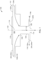
- FIG. 1 depicts an example of a fluid delivery system 100 including a fluid ejector 101, e.g., for a printhead 200 shown in FIG. 2 .
- the fluid delivery system 100 has a configuration of flow pathways that enables ejection of fluid from a pumping chamber 102 of the fluid ejector 101.
- the fluid ejector 101 includes flow pathways to transport fluid from a reservoir to a nozzle 114 of the fluid ejector 101.
- the fluid ejector 101 includes a descender 104 having a first end 106 and a second end 108.
- the first end 106 defines a first fluid flow pathway 112 between the pumping chamber 102 and the nozzle 114.
- the nozzle 114 is disposed at the second end 108 of the descender 104.
- a second fluid flow pathway 116 is defined at the second end 108 of the descender 104.
- the second fluid flow pathway 116 corresponds to a recirculation pathway to recirculate fluid in an ejection operation, e.g., a printing operation.
- the recirculated fluid is, for example, returned to the reservoir and reused for a subsequent ejection operation, e.g., a subsequent printing operation.
- the fluid ejector 101 includes an actuator 118 operable to pump fluid through the pumping chamber 102 toward the nozzle 114.
- the first fluid flow pathway 112 corresponds to a fluid flow pathway for fluid that is pumped out of the pumping chamber 102. If the pumping chamber receives fluid from multiple fluid flow pathways, the first fluid flow pathway 112 receives the fluid from the multiple fluid flow pathways such that a single flow of fluid is directed through the descender 104.
- the printhead 200 ejects droplets of fluid, such as ink, biological liquids, polymers, liquids for forming electronic components, or other types of fluid, onto a surface.
- the printhead 200 includes one or more fluid ejectors 101, each fluid ejector having a corresponding actuator 118, as described with respect to FIG. 1 .
- the printhead 200 includes a substrate 300 coupled to a deformable membrane 303 of the fluid ejector 101 and to an interposer assembly 214.
- the substrate 300 is, in some cases, a monolithic semiconductor body, such as a silicon substrate.
- the substrate has passages formed therethrough that define flow pathways for fluid through the substrate 300.
- the substrate 300 and the membrane 303 together define the pumping chamber 102.
- the substrate 300 defines the fluid conduits of the fluid ejector 101, e.g., the pumping chamber 102, the descender 104, the nozzle 114, as well as additional fluid passages 346 described below.
- the printhead 200 includes a casing 202 having an interior volume divided into a fluid supply chamber 204 and a fluid return chamber 206.
- the interior volume is divided by a dividing structure 208.
- the dividing structure 208 includes, for example, an upper divider 210 and a lower divider 212.
- the bottom of the fluid supply chamber 204 and the fluid return chamber 206 is defined by the top surface of the interposer assembly 214.
- the fluid supply chamber 204 includes a reservoir to contain a supply of fluid to be ejected from the printhead 200, e.g., to be ejected through the ejector 101.
- the reservoir of the fluid supply chamber 204 supplies fluid to the pumping chamber 102.
- the fluid return chamber 206 includes a reservoir to contain fluid recirculated through the printhead 200 through the second fluid flow pathway 116 described with respect to FIG. 1 .
- the fluid supply chamber 204 has a reservoir to contain the supply of fluid to be ejected from the printhead 200 in the short term, e.g., during a current printing operation or during a next time period.
- the fluid supply chamber is also in fluidic connection with another, upstream reservoir that contains fluid (e.g., ink) for later use.
- the upstream reservoir may be an ink cartridge or ink supply.
- the interposer assembly 214 is attachable to the casing 202, such as by bonding or another mechanism of attachment.
- the interposer assembly 214 includes, for example, an upper interposer 216 and a lower interposer 218.
- the lower interposer 218 is positioned between the upper interposer 216 and the substrate 300.
- a flow pathway 226 is formed to connect, e.g., fluidically connect, the fluid supply chamber 204 to the fluid return chamber 206.
- the upper interposer 216 includes an inlet 330 to the flow pathway 226 and an outlet 332 from the flow pathway 226.
- the inlet 330 and the outlet 332, for example, are formed as apertures in the upper interposer 216.
- the flow pathway 226 is, for example, formed in the upper interposer 216, the lower interposer 218, and the substrate 300.
- the flow pathway 226 enables flow of fluid from the supply chamber 204, through the substrate 300, into the inlet 330, and to the fluid ejector 101 for ejection of fluid from the printhead 200.
- the actuator 118 of the ejector 101 when driven, ejects fluid from the pumping chamber 102 through the nozzle 114.
- the flow pathway 226 also enables flow of fluid from the fluid ejector 101, into the outlet 332, and into the return chamber 206.
- the fluid ejector 101 includes the nozzle 114. Fluid is selectively ejected from the nozzle 114 of the fluid ejector 101.
- the fluid is, for example, ink that is ejected onto a surface to print an image on the surface.
- the nozzle 114 is formed in a nozzle layer of the substrate 300, e.g., on a bottom surface or a top surface of the substrate 300.
- a portion of fluid flows through an inlet 222 of the fluid ejector 101, through the pumping chamber 102, through the first end 106 of the descender 104, through the descender 104, through the fluid ejector 101, and out of the printhead 200 through the nozzle 114.
- a portion of fluid flows through the inlet 222, through the pumping chamber 102, through the first end 106 of the descender 104, through the descender 104, and through an outlet 224 of the fluid ejector 101.
- the inlet 222 is, for example, an inlet to the pumping chamber 102.
- the outlet 224 is, for example, an outlet from the descender 104.
- the inlet 222 is, for example, connected to a reservoir to enable fluid flow from the reservoir, e.g., the supply chamber 204.
- An inlet feed channel 304 connects the supply chamber 204 to the inlet 222 of the fluid ejector 101.
- the inlet 222 includes a first end connected to the supply chamber 204 through the inlet fluid channel 304 and a second end connected to the pumping chamber 102.
- FIGS. 1 and 2 show various passages, such as pumping chambers and descenders, these components may not all be in a common plane. In some embodiments, different passages and other features may lie in different planes. In some embodiments, portions of a single feature may lie in different planes, e.g., a fluid passage may be sloped so as to cross multiple planes within the printhead 200. In addition, the relative dimensions of the components may vary, and the dimensions of some components have been exaggerated in for illustrative purposes.
- the nozzle dimensions and the dimensions and shape of the fluid flow paths can affect printing quality, printing resolution, and energy efficiencies of the printing device.
- the substrate 300 includes many nozzles 342 such as the type described above with respect to FIGS. 1 and 2 , arranged in an array 340.
- the substrate 300 includes multiple flow pathways to transport fluid from reservoirs to eject the fluid, to recirculate the fluid from near the nozzles to be ejected during a subsequent ejection operation, and/or to remove ink from the array 340.
- These flow pathways include fluid passages 346 (seen in FIG. 3B ).
- the fluid passages 346 direct ink from a distant reservoir (e.g., an ink cartridge) to a closer reservoir (e.g., the supply chamber 204).
- Multiple supply chambers 204 are defined within the substrate 300 to allow fluid to flow to each of the multiple nozzles 342 in the array 340.
- multiple fluid return chambers 206 can collect unused and non-recirculated ink for flow along additional fluid passages 346 and out from the substrate 300.
- the bottom surface of the substrate 300 includes several slots and holes that make up the various fluid channels and the nozzles 342.
- Each of these bottom-surface features reduce the surface area 320 of the bottom surface.
- increasing the surface area 320 can prevent crack prorogation, and provides additional area for adhesive layering (e.g., addition of epoxy or other adhesive to attach the substrate 300 to other components such as the casing 202).
- adhesive layering e.g., addition of epoxy or other adhesive to attach the substrate 300 to other components such as the casing 202).
- FIG. 4A is a close-up of a portion of FIG. 3B , showing a fluid passage 346 in greater detail.
- the fluid passage 346 has a curved, non-linear profile as viewed from below.
- the fluid passage 346 is generally a slot or trench with a long, curved passage machined (e.g., milled, etched, or otherwise fabricated) into the surface of the substrate 300.
- the fluid passage 346 has an opening on the bottom surface of the substrate 300.
- One or more of the width and the cross sectional profile of the fluid passage 346 can vary along the length of the fluid passage.
- the width of the opening of the fluid passage 346 changes along the length of the fluid passage, with the width at the portion marked A being greater than the width at the portion marked B.
- the cross sectional profile of the fluid passage 346 also changes along the length of the fluid passage.
- FIG. 4B shows a cross sectional view of the fluid passage 346 at portion A
- FIG. 4C shows a cross sectional view of the fluid passage 346 at portion B.
- the fluid passage 346 has a generally regular cross section 352A, e.g., a rectangular cross section.
- Sides 354A of the fluid passage 346 are generally straight and substantially parallel.
- the width of the fluid passage 346 at portion A is substantially constant from the opening 355A of the fluid passage 346 to the bottom 356A of the fluid passage 346.
- the sides 354A of the fluid passage 346 meet the bottom 356A of the fluid passage 346 at curved corners 358A.
- the curved corners 358A are rounded with a radius of curvature 360A so that the sides 354A do not meet the bottom 356A at a right angle.
- FIG. 4C shows a cross section 352B of the fluid passage 346 at portion B from FIG. 4A .
- the cross section 352B is not regular and sides 354B of the fluid passage 346 curve more than once before meeting the bottom 356B of the fluid passage 346.
- the width of the fluid passage 346 at portion B varies across the height of the fluid passage such that the fluid passage is undercut, having a bottom portion 364 at the bottom 356B of the fluid passage 346 that is wider than a top portion 362 at the opening 355B of the fluid passage 346. In some instances, the bottom portion 364 is 30-40% wider than the top portion 362.
- the sides 354B of the cross section 352B meet the bottom 356B of the fluid passage 346 at curved corners 358B that are rounded with a radius of curvature 360B.
- the undercut shape of the fluid passage 346 as shown in FIG. 4C advantageously provides a fluid passage with a large cross sectional area and narrow surface opening 355B.
- the size of the opening 355B of the fluid passage 346 on the bottom surface of the substrate 300 can be smaller than the opening 355A would be in a non-undercut configuration of the same cross sectional area, enabling the surface area 320 of the bottom surface of the substrate 300 to be larger.
- a wide space can exist between the opening 355B of the fluid passage 346 and the substrate edge 350 or some other feature such as feature 366 in FIG. 4A .
- the fluid passage 346 at portion B, with the undercut cross section 352B, has a cross sectional area (e.g., the area of both the top portion 362 and the bottom portion 364) that is greater than the cross sectional area of a fluid passage with a rectangular cross sectional area having the width of the top portion 362.
- the fluid resistance of a fluid flowing in a channel (such as ink in the fluid passage 346) is directly proportional to the channel's width. Fluid flowing in a narrow channel (e.g., a rectangular cross section channel having the width of the top portion 362) experiences a higher fluid resistance than that of the same fluid flowing in a wider (but shallower) channel of the same cross sectional area.
- the undercut profile of the cross section 352B reduces how much fluid flows through a narrowed area of the fluid passage 346, e.g., through the top portion 362, reducing the overall fluid resistance as compared to a fluid passage with rectangular cross section of the width of the top portion 362.
- the sum of the area of the top portion 362 and the area of the bottom portion 364 of the cross section 352B can be equal to the area of the cross section 352A, or greater than or less than the area of the cross section 352A.
- the width of the bottom portion 364 at portion B can be wider than the width of the cross section 352A.
- the radius of curvature 360A and radius of curvature 360B can be the same, or can differ.
- the radius of curvature 360B can be smaller than the radius of curvature 360A.
- the radius of curvature 360A and radius of curvature 360B affect the fluid resistance as it is a function of the shape, the cross sectional area, and the aspect ratio of a fluid channel.
- the lowest resistance per unit area is achieved with a circular duct, whereas a square duct of the same area has more resistance because the inscribed circle is smaller and the flow in the corners is small.
- the radius of curvature 360A and radius of curvature 360B help improve the uniformity of flow in the channel.
- FIG. 4D there are several manufacturing steps to create an undercut cross sectional profile such as that shown in FIG. 4C .
- a cutter is used to drill or mill the fluid passage to the desired top width 366 (e.g., the width of top portion 362) by removing material from the surface of the substrate 300 down to the desired depth 370 of the cross section 352B. This machining creates a straight vertical slot of width 366, as shown by the dotted lines.
- a wider cutter such as a T-slot cutter or a relieved cutter, is inserted into the slot of width 366 and height 370 along the centerline of the slot.
- the wider cutter is used to create the wider bottom of width 368 by shifting the wider cutter to the left and following the edge of the slot for the desired length, and then shifting the wider cutter to the right and following the edge for the desired length on the corresponding side facing the left edge.
- the curved corners 358B and radius of curvature 360B can be formed using a rounding tool. Alternatively, the curved corners 358 and radius of curvature 360 can result from the shape of the wider cutter.
- the resulting cross section 352B is symmetric about its central axis. The result of these steps is an undercut slot with a bottom wider than the throat, resulting in reduced flow resistance while reducing the area removed from the surface of the printhead.
- the size and shape of the cross section of the fluid passages 346 can vary along the length of each fluid passage. For example, slots having undercut cross sectional profiles with different dimensions can be present on the same printhead and within the same fluid passage. Modifying the profiles of the fluid passages can compensate for flow imbalance within the nozzle array 340, e.g., by increasing or decreasing the fluid resistance to differing parts of the array 340.
- a fluid passage 346 may itself not lie in a common plane along its entire length.
- a fluid passage 346 may have a portion that is positioned deeper within the substrate 300 (referred to as a deep portion of the fluid passage) than another portion of the fluid passage 346 (referred to as a shallow portion of the fluid passage).
- the fluid passage 346 has a general downwards slant from left to right, as well as a more precipitous change in height at a connecting passage 384.
- any abrupt changes in the depth of the fluid passage 346 act as a bubble trap for undesirable air bubbles in the ink flow, such as air bubbles created from air entering imperfectly formed nozzles. Air bubbles in the ink flow can change the acoustic characteristics of the fluid ejectors 101, or even completely impede the ink flow, negatively affecting the quality and consistency of the printing action carried out by the printhead 200.
- a sharp transition from a deep portion to a shallow portion of a fluid passage creates a vertical step that acts as a trap for any air bubble in the ink flow.
- the fluid passage 346 can be angled such that the depth of the fluid passage 346 changes from one depth 380 to another depth 382 at the fluid connecting passage 384.
- the angle at the fluid connecting passage 384 is not sharp, e.g., the angle is less than 90 degrees. For instance, the angle can be between 30 to 75 degrees.
- the fluid connecting passage 384 can be a simple height transition from one depth to another (as in FIG. 5 and FIG. 7 ) or can also include a branching of fluid passages 346 where multiple fluid channels are fluidically connected, e.g., a junction.
- the fluid connecting passage 384 can be straight up and down (e.g., moves ink from one gravitational level to another gravitational level). In other instances, the fluid connecting passage 384 can also move the ink laterally along the substrate 300.
- the rounded corners 358A or 358B of the fluid passage 346 assist in moving air bubbles along the center of the fluid passage 346 without the air bubble becoming trapped. If the corners 358A, 358B of the fluid passage 346 were sharp (e.g., at right angles), the fluid flow would tend to force any air bubble into the corners. For fluid flow in a channel, the fluid flow in corners is slower than at other portions of the channel, such as at the center. The air bubble forced into a sharp corner would then become more easily trapped due to the slower fluid flow at the corner.
- the rounded corners 358A or 358B with their radii of curvature 360A, 360B do not provide low-flow sharp corners. Instead, the rounded corners 358A, 358B encourage an air bubble to go to the center of the channel, keeping the air bubble in the position where most fluid flows around it and thus is exposed to a relatively strong force to move the air bubble along the fluid passage 346 in the direction of the fluid flow.
- the fluid passage 346 having a non-uniform cross section can encourage air bubbles to flow with the fluid.
- the cross sectional area of the fluid passage 346 can vary along the length of the fluid passage, as discussed above. Positioning a connecting passage 384 at a location where the cross sectional area of the fluid passage is narrow (and hence fluid flow is fast) encourages air bubbles to move with the fluid to a greater extent than positioning the connecting passage 384 at a place where the cross sectional area is wide and the fluid flow slow (or at a place with a uniform, unchanging cross section).
- a printhead 200 is more robust and easier to purge of air bubbles that are injected into the ink flow.
Landscapes
- Particle Formation And Scattering Control In Inkjet Printers (AREA)
- Ink Jet (AREA)
Description
- This application claims priority under 35 U.S.C. §120 from
U.S. provisional application number 62/734,384 filed on September 21, 2018 - This disclosure relates to print head flow channels.
- Printing high quality, high-resolution images with an inkjet printer generally requires a printer that accurately ejects a desired quantity of ink at a specified location on a printing medium. Typically, a multitude of densely packed ink ejecting devices, each including a nozzle and an associated ink flow path, are formed in a printhead structure. The ink flow path connects an ink storage unit, such as an ink reservoir or cartridge, to the nozzle. The ink flow path includes a pumping chamber. In the pumping chamber, ink can be pressurized to flow toward a descender region that terminates in the nozzle. The ink is expelled out of an opening at the end of the nozzle and lands on a printing medium. The medium can be moved relative to the fluid ejection device. The ejection of a fluid droplet from a particular nozzle can be timed with the movement of the medium to place a fluid droplet at a desired location on the medium.
US-A-2016/082731 describes that in its liquid ejection head substrate, the blocking of supply paths or the reduction of bubble releasability does not occur when the liquid ejection head substrate is mounted on a support member using an adhesive and the opening width of the supply paths can be reduced. - In one aspect, an apparatus includes the features of claims 1 to 6.
- Implementations include one or more of the features. The width of the fluid passage near the second surface of the substrate is smaller than the width near the bottom of the fluid passage. The width of the fluid passage near the bottom of the fluid passage is about 30% to about 40% greater than the width near the surface of the substrate. The cross section of the fluid passage is symmetric about a longitudinal axis extending from a top to the bottom of the fluid passage. The fluid passage has curved corners joining a bottom of the fluid passage to walls of the fluid passage. The curved corners have a radius of curvature.
- In a further aspect, an apparatus includes the features of claims 7 to 13.
- Implementations include one or more of the features. The fluid passage has rounded corners joining the first portion and the second portion. The connecting passage has an angle of about 30 degrees to about 75 degrees. The first portion is at a first distance from the surface and the second portion is at a second distance from the surface. The fluid passage is fluidically connected to a reservoir remote from the substrate. The fluid passage fluidically connects fluid from the remote reservoir to the nozzle. A plurality of nozzles is included, and the fluid passage fluidically connects fluid from the remote reservoir to the plurality of nozzles.
- In a further aspect, a system includes the features of claim 14.
- In a further aspect, a system includes The features of claim 15.
- Advantages of the approaches described here may include, but are not limited to, one or more of the advantages described below. The configuration of the flow pathways can improve the performance of the printhead by encouraging undesirable air bubbles to move freely along the flow pathways with the fluid flow and be purged from the printhead. The configuration of the flow pathways can reduce fluid resistance, thereby increasing the reliability of ink being introduced into the pumping chamber that can be actuated to eject fluid from the printhead as well as enabling air bubbles to move along the flow pathways without becoming trapped.
- The details of one or more embodiments of the invention are set forth in the accompanying drawings and the description below. Other features, objects, and advantages of the invention will be apparent from the description and drawings, and from the claims.
-
-
FIG. 1 is a side view of a fluid delivery system. -
FIG. 2 is a cross-sectional view of a printhead -
FIGS. 3A and 3B are top and bottom views of a print array. -
FIG. 4A is a view of a portion ofFIG. 3B . -
FIGS. 4B and 4C are cross sections through the designated lines shown inFIG. 4A . -
FIG. 4D is a semi-perspective view of the cross section ofFIG. 4C . -
FIG. 5 is a side view of a fluid passage. -
FIGS. 6 and7 are views of fluid passages viewed from below. - Like reference symbols in the various drawings indicate like elements.
- A fluid ejector, e.g., for an inkjet printer, can include flow pathways that enable an actuator to be actuated rapidly, e.g., at a rate between 10 kHz and 1 MHz, 0 and 250 kHz, 0 and 1 MHz, or higher. Fluid ejectors can enable the actuators associated with the fluid ejectors to be rapidly driven to eject fluid from the fluid ejectors. Fluid drop ejection can be implemented with a substrate, for example, a microelectromechanical system (MEMS) substrate, including a fluid flow body, a membrane, and a nozzle layer. The flow path body has a fluid flow path formed therein, which can include a fluid filled passage, a fluid pumping chamber, a descender, and a nozzle having an outlet. An actuator can be located on a surface of the membrane opposite the flow path body and proximate to the fluid pumping chamber. When the actuator is actuated, the actuator imparts a pressure pulse to the fluid pumping chamber to cause ejection of a droplet of fluid through the outlet of the nozzle. Frequently, the flow path body includes multiple fluid flow paths and nozzles, such as a densely packed array of identical nozzles with their respective associated flow paths. A fluid droplet ejection system can include the substrate and a source of fluid for the substrate. A fluid reservoir can be fluidically connected to the substrate for supplying fluid for ejection. The fluid can be, for example, a chemical compound, a biological substance, or ink.
-
FIG. 1 depicts an example of afluid delivery system 100 including afluid ejector 101, e.g., for aprinthead 200 shown inFIG. 2 . Thefluid delivery system 100 has a configuration of flow pathways that enables ejection of fluid from apumping chamber 102 of thefluid ejector 101. Thefluid ejector 101 includes flow pathways to transport fluid from a reservoir to anozzle 114 of thefluid ejector 101. Thefluid ejector 101 includes adescender 104 having afirst end 106 and asecond end 108. Thefirst end 106 defines a firstfluid flow pathway 112 between the pumpingchamber 102 and thenozzle 114. Thenozzle 114 is disposed at thesecond end 108 of thedescender 104. A second fluid flow pathway 116 is defined at thesecond end 108 of thedescender 104. The second fluid flow pathway 116, for example, corresponds to a recirculation pathway to recirculate fluid in an ejection operation, e.g., a printing operation. The recirculated fluid is, for example, returned to the reservoir and reused for a subsequent ejection operation, e.g., a subsequent printing operation. Thefluid ejector 101 includes anactuator 118 operable to pump fluid through thepumping chamber 102 toward thenozzle 114. - The first
fluid flow pathway 112, for example, corresponds to a fluid flow pathway for fluid that is pumped out of thepumping chamber 102. If the pumping chamber receives fluid from multiple fluid flow pathways, the firstfluid flow pathway 112 receives the fluid from the multiple fluid flow pathways such that a single flow of fluid is directed through thedescender 104. - Referring to
FIG. 2 , theprinthead 200 ejects droplets of fluid, such as ink, biological liquids, polymers, liquids for forming electronic components, or other types of fluid, onto a surface. Theprinthead 200 includes one or morefluid ejectors 101, each fluid ejector having a correspondingactuator 118, as described with respect toFIG. 1 . Theprinthead 200 includes asubstrate 300 coupled to a deformable membrane 303 of thefluid ejector 101 and to aninterposer assembly 214. Thesubstrate 300 is, in some cases, a monolithic semiconductor body, such as a silicon substrate. The substrate has passages formed therethrough that define flow pathways for fluid through thesubstrate 300. In some implementations, thesubstrate 300 and the membrane 303 together define thepumping chamber 102. Thesubstrate 300, for example, defines the fluid conduits of thefluid ejector 101, e.g., thepumping chamber 102, thedescender 104, thenozzle 114, as well as additionalfluid passages 346 described below. - The
printhead 200 includes acasing 202 having an interior volume divided into afluid supply chamber 204 and afluid return chamber 206. In some cases, the interior volume is divided by a dividingstructure 208. The dividingstructure 208 includes, for example, anupper divider 210 and alower divider 212. The bottom of thefluid supply chamber 204 and thefluid return chamber 206 is defined by the top surface of theinterposer assembly 214. - The
fluid supply chamber 204 includes a reservoir to contain a supply of fluid to be ejected from theprinthead 200, e.g., to be ejected through theejector 101. The reservoir of thefluid supply chamber 204 supplies fluid to thepumping chamber 102. Thefluid return chamber 206 includes a reservoir to contain fluid recirculated through theprinthead 200 through the second fluid flow pathway 116 described with respect toFIG. 1 . Thefluid supply chamber 204 has a reservoir to contain the supply of fluid to be ejected from theprinthead 200 in the short term, e.g., during a current printing operation or during a next time period. The fluid supply chamber is also in fluidic connection with another, upstream reservoir that contains fluid (e.g., ink) for later use. For example, the upstream reservoir may be an ink cartridge or ink supply. - The
interposer assembly 214 is attachable to thecasing 202, such as by bonding or another mechanism of attachment. Theinterposer assembly 214 includes, for example, anupper interposer 216 and alower interposer 218. Thelower interposer 218 is positioned between theupper interposer 216 and thesubstrate 300. - A
flow pathway 226 is formed to connect, e.g., fluidically connect, thefluid supply chamber 204 to thefluid return chamber 206. Theupper interposer 216 includes aninlet 330 to theflow pathway 226 and anoutlet 332 from theflow pathway 226. Theinlet 330 and theoutlet 332, for example, are formed as apertures in theupper interposer 216. Theflow pathway 226 is, for example, formed in theupper interposer 216, thelower interposer 218, and thesubstrate 300. Theflow pathway 226 enables flow of fluid from thesupply chamber 204, through thesubstrate 300, into theinlet 330, and to thefluid ejector 101 for ejection of fluid from theprinthead 200. Theactuator 118 of theejector 101, when driven, ejects fluid from thepumping chamber 102 through thenozzle 114. Theflow pathway 226 also enables flow of fluid from thefluid ejector 101, into theoutlet 332, and into thereturn chamber 206. - As described with respect to
FIG. 1 , thefluid ejector 101 includes thenozzle 114. Fluid is selectively ejected from thenozzle 114 of thefluid ejector 101. The fluid is, for example, ink that is ejected onto a surface to print an image on the surface. Thenozzle 114 is formed in a nozzle layer of thesubstrate 300, e.g., on a bottom surface or a top surface of thesubstrate 300. - In one example, to be ejected from the
printhead 200, a portion of fluid flows through an inlet 222 of thefluid ejector 101, through thepumping chamber 102, through thefirst end 106 of thedescender 104, through thedescender 104, through thefluid ejector 101, and out of theprinthead 200 through thenozzle 114. To be recirculated, a portion of fluid flows through the inlet 222, through thepumping chamber 102, through thefirst end 106 of thedescender 104, through thedescender 104, and through an outlet 224 of thefluid ejector 101. The inlet 222 is, for example, an inlet to thepumping chamber 102. The outlet 224 is, for example, an outlet from thedescender 104. - The inlet 222 is, for example, connected to a reservoir to enable fluid flow from the reservoir, e.g., the
supply chamber 204. An inlet feed channel 304 connects thesupply chamber 204 to the inlet 222 of thefluid ejector 101. The inlet 222 includes a first end connected to thesupply chamber 204 through the inlet fluid channel 304 and a second end connected to thepumping chamber 102. - While
FIGS. 1 and2 show various passages, such as pumping chambers and descenders, these components may not all be in a common plane. In some embodiments, different passages and other features may lie in different planes. In some embodiments, portions of a single feature may lie in different planes, e.g., a fluid passage may be sloped so as to cross multiple planes within theprinthead 200. In addition, the relative dimensions of the components may vary, and the dimensions of some components have been exaggerated in for illustrative purposes. - The nozzle dimensions and the dimensions and shape of the fluid flow paths can affect printing quality, printing resolution, and energy efficiencies of the printing device.
- Referring to
FIGS. 3A and 3B , thesubstrate 300 includesmany nozzles 342 such as the type described above with respect toFIGS. 1 and2 , arranged in anarray 340. Thesubstrate 300 includes multiple flow pathways to transport fluid from reservoirs to eject the fluid, to recirculate the fluid from near the nozzles to be ejected during a subsequent ejection operation, and/or to remove ink from thearray 340. These flow pathways include fluid passages 346 (seen inFIG. 3B ). Thefluid passages 346 direct ink from a distant reservoir (e.g., an ink cartridge) to a closer reservoir (e.g., the supply chamber 204).Multiple supply chambers 204 are defined within thesubstrate 300 to allow fluid to flow to each of themultiple nozzles 342 in thearray 340. Similarly, multiplefluid return chambers 206 can collect unused and non-recirculated ink for flow along additionalfluid passages 346 and out from thesubstrate 300. - As can be seen in
FIG. 3B , the bottom surface of thesubstrate 300 includes several slots and holes that make up the various fluid channels and thenozzles 342. Each of these bottom-surface features reduce thesurface area 320 of the bottom surface. However, it is beneficial to increase thesurface area 320 that is not given over tofluid passages 346. For example, increasing thesurface area 320 can prevent crack prorogation, and provides additional area for adhesive layering (e.g., addition of epoxy or other adhesive to attach thesubstrate 300 to other components such as the casing 202). It is desirable to create as wide an area as possible between the outermostfluid passages 346 and theedges 350 of the printhead, while not increasing the overall size of the printhead. It is also desirable to increase the distance betweenfluid passages 346 and theedges 350 of the printhead, or to other features. -
FIG. 4A is a close-up of a portion ofFIG. 3B , showing afluid passage 346 in greater detail. Thefluid passage 346 has a curved, non-linear profile as viewed from below. Thefluid passage 346 is generally a slot or trench with a long, curved passage machined (e.g., milled, etched, or otherwise fabricated) into the surface of thesubstrate 300. Thefluid passage 346 has an opening on the bottom surface of thesubstrate 300. - One or more of the width and the cross sectional profile of the
fluid passage 346 can vary along the length of the fluid passage. In the example ofFIG. 4A , the width of the opening of thefluid passage 346 changes along the length of the fluid passage, with the width at the portion marked A being greater than the width at the portion marked B. The cross sectional profile of thefluid passage 346 also changes along the length of the fluid passage.FIG. 4B shows a cross sectional view of thefluid passage 346 at portion A andFIG. 4C shows a cross sectional view of thefluid passage 346 at portion B. - Referring to
Fig. 4B , at portion A of thefluid passage 346, thefluid passage 346 has a generallyregular cross section 352A, e.g., a rectangular cross section.Sides 354A of thefluid passage 346 are generally straight and substantially parallel. The width of thefluid passage 346 at portion A is substantially constant from theopening 355A of thefluid passage 346 to the bottom 356A of thefluid passage 346. Thesides 354A of thefluid passage 346 meet the bottom 356A of thefluid passage 346 atcurved corners 358A. Thecurved corners 358A are rounded with a radius ofcurvature 360A so that thesides 354A do not meet the bottom 356A at a right angle. -
FIG. 4C shows across section 352B of thefluid passage 346 at portion B fromFIG. 4A . Unlike thecross section 352A, thecross section 352B is not regular and sides 354B of thefluid passage 346 curve more than once before meeting the bottom 356B of thefluid passage 346. The width of thefluid passage 346 at portion B varies across the height of the fluid passage such that the fluid passage is undercut, having abottom portion 364 at the bottom 356B of thefluid passage 346 that is wider than atop portion 362 at theopening 355B of thefluid passage 346. In some instances, thebottom portion 364 is 30-40% wider than thetop portion 362. Thesides 354B of thecross section 352B meet the bottom 356B of thefluid passage 346 atcurved corners 358B that are rounded with a radius ofcurvature 360B. - The undercut shape of the
fluid passage 346 as shown inFIG. 4C advantageously provides a fluid passage with a large cross sectional area andnarrow surface opening 355B. With this undercut configuration, the size of theopening 355B of thefluid passage 346 on the bottom surface of thesubstrate 300 can be smaller than theopening 355A would be in a non-undercut configuration of the same cross sectional area, enabling thesurface area 320 of the bottom surface of thesubstrate 300 to be larger. For instance, with an undercutfluid passage 346, a wide space can exist between the opening 355B of thefluid passage 346 and thesubstrate edge 350 or some other feature such asfeature 366 inFIG. 4A . - The
fluid passage 346 at portion B, with the undercutcross section 352B, has a cross sectional area (e.g., the area of both thetop portion 362 and the bottom portion 364) that is greater than the cross sectional area of a fluid passage with a rectangular cross sectional area having the width of thetop portion 362. The fluid resistance of a fluid flowing in a channel (such as ink in the fluid passage 346) is directly proportional to the channel's width. Fluid flowing in a narrow channel (e.g., a rectangular cross section channel having the width of the top portion 362) experiences a higher fluid resistance than that of the same fluid flowing in a wider (but shallower) channel of the same cross sectional area. The undercut profile of thecross section 352B reduces how much fluid flows through a narrowed area of thefluid passage 346, e.g., through thetop portion 362, reducing the overall fluid resistance as compared to a fluid passage with rectangular cross section of the width of thetop portion 362. - The sum of the area of the
top portion 362 and the area of thebottom portion 364 of thecross section 352B can be equal to the area of thecross section 352A, or greater than or less than the area of thecross section 352A. The width of thebottom portion 364 at portion B can be wider than the width of thecross section 352A. The radius ofcurvature 360A and radius ofcurvature 360B can be the same, or can differ. For example, the radius ofcurvature 360B can be smaller than the radius ofcurvature 360A. The radius ofcurvature 360A and radius ofcurvature 360B affect the fluid resistance as it is a function of the shape, the cross sectional area, and the aspect ratio of a fluid channel. Generally, the lowest resistance per unit area is achieved with a circular duct, whereas a square duct of the same area has more resistance because the inscribed circle is smaller and the flow in the corners is small. The radius ofcurvature 360A and radius ofcurvature 360B help improve the uniformity of flow in the channel. - Referring to
FIG. 4D , there are several manufacturing steps to create an undercut cross sectional profile such as that shown inFIG. 4C . First, a cutter is used to drill or mill the fluid passage to the desired top width 366 (e.g., the width of top portion 362) by removing material from the surface of thesubstrate 300 down to the desireddepth 370 of thecross section 352B. This machining creates a straight vertical slot ofwidth 366, as shown by the dotted lines. Next, a wider cutter, such as a T-slot cutter or a relieved cutter, is inserted into the slot ofwidth 366 andheight 370 along the centerline of the slot. Once inserted, the wider cutter is used to create the wider bottom ofwidth 368 by shifting the wider cutter to the left and following the edge of the slot for the desired length, and then shifting the wider cutter to the right and following the edge for the desired length on the corresponding side facing the left edge. Thecurved corners 358B and radius ofcurvature 360B can be formed using a rounding tool. Alternatively, the curved corners 358 and radius of curvature 360 can result from the shape of the wider cutter. Typically, the resultingcross section 352B is symmetric about its central axis. The result of these steps is an undercut slot with a bottom wider than the throat, resulting in reduced flow resistance while reducing the area removed from the surface of the printhead. - The size and shape of the cross section of the
fluid passages 346 can vary along the length of each fluid passage. For example, slots having undercut cross sectional profiles with different dimensions can be present on the same printhead and within the same fluid passage. Modifying the profiles of the fluid passages can compensate for flow imbalance within thenozzle array 340, e.g., by increasing or decreasing the fluid resistance to differing parts of thearray 340. - As mentioned above, different components interacting with and within the
substrate 300 may not all lie in a common plane. Referring toFIG. 5 , afluid passage 346 may itself not lie in a common plane along its entire length. For instance, afluid passage 346 may have a portion that is positioned deeper within the substrate 300 (referred to as a deep portion of the fluid passage) than another portion of the fluid passage 346 (referred to as a shallow portion of the fluid passage). In the example shown, thefluid passage 346 has a general downwards slant from left to right, as well as a more precipitous change in height at a connectingpassage 384. - Any abrupt changes in the depth of the
fluid passage 346 act as a bubble trap for undesirable air bubbles in the ink flow, such as air bubbles created from air entering imperfectly formed nozzles. Air bubbles in the ink flow can change the acoustic characteristics of thefluid ejectors 101, or even completely impede the ink flow, negatively affecting the quality and consistency of the printing action carried out by theprinthead 200. - A sharp transition from a deep portion to a shallow portion of a fluid passage creates a vertical step that acts as a trap for any air bubble in the ink flow. As shown in
FIG. 5 , thefluid passage 346 can be angled such that the depth of thefluid passage 346 changes from onedepth 380 to anotherdepth 382 at thefluid connecting passage 384. The angle at thefluid connecting passage 384 is not sharp, e.g., the angle is less than 90 degrees. For instance, the angle can be between 30 to 75 degrees. Thefluid connecting passage 384 can be a simple height transition from one depth to another (as inFIG. 5 andFIG. 7 ) or can also include a branching offluid passages 346 where multiple fluid channels are fluidically connected, e.g., a junction. In some instances, thefluid connecting passage 384 can be straight up and down (e.g., moves ink from one gravitational level to another gravitational level). In other instances, thefluid connecting passage 384 can also move the ink laterally along thesubstrate 300. - As seen in
FIGS. 5-7 , therounded corners fluid passage 346 assist in moving air bubbles along the center of thefluid passage 346 without the air bubble becoming trapped. If thecorners fluid passage 346 were sharp (e.g., at right angles), the fluid flow would tend to force any air bubble into the corners. For fluid flow in a channel, the fluid flow in corners is slower than at other portions of the channel, such as at the center. The air bubble forced into a sharp corner would then become more easily trapped due to the slower fluid flow at the corner. - The
rounded corners curvature rounded corners fluid passage 346 in the direction of the fluid flow. - In some implementations, the
fluid passage 346 having a non-uniform cross section can encourage air bubbles to flow with the fluid. The cross sectional area of thefluid passage 346 can vary along the length of the fluid passage, as discussed above. Positioning a connectingpassage 384 at a location where the cross sectional area of the fluid passage is narrow (and hence fluid flow is fast) encourages air bubbles to move with the fluid to a greater extent than positioning the connectingpassage 384 at a place where the cross sectional area is wide and the fluid flow slow (or at a place with a uniform, unchanging cross section). - The result of the above features is that a
printhead 200 is more robust and easier to purge of air bubbles that are injected into the ink flow.
Claims (15)
- An apparatus comprising:a nozzle (342) formed on a first surface of a substrate (300);a fluid passage (346) defined in the substrate (300) and fluidically connected to the nozzle (342), wherein during use of the apparatus, fluid in the fluid passage (346) is supplied to the nozzle (342),
the fluid passage (346) being nonlinear along at least a portion of a length of the fluid passage (346) and having a cross section (352B) that varies along the length of the fluid passage (346), wherein the fluid passage (346) has a width near a second surface of the substrate (300) that is different from a width near a bottom (356B) of the fluid passage (346); anda recirculation flow passage defined in the substrate (300) and fluidically connected to the nozzle (342), wherein during use of the apparatus, fluid that is not ejected from the nozzle (342) is recirculated through the recirculation flow passage. - The apparatus of claim 1, wherein the width of the fluid passage (346) near the second surface of the substrate (300) is smaller than the width near the bottom (356B) of the fluid passage (346).
- The apparatus of claim 2, wherein the width of the fluid passage (346) near the bottom of the fluid passage (346) is about 30% to about 40% greater than the width near the surface of the substrate (300).
- The apparatus of claim 1, wherein the cross section (352B) of the fluid passage (346) is symmetric about a longitudinal axis extending from a top to the bottom (356B) of the fluid passage (346).
- The apparatus of claim 1, wherein the fluid passage (346) has curved corners (358B) joining a bottom of the fluid passage to walls of the fluid passage (346).
- The apparatus of claim 5, wherein the curved corners (358B) have a radius of curvature (360B).
- An apparatus comprising:a nozzle (342) formed on a surface of a substrate (300);an actuator (118) defining at least a portion of a pumping chamber fluidically connected to the nozzle (342), wherein actuation of the actuator (118) causes ejection of fluid from the nozzle (342);a fluid passage (346) defined in the substrate (300) and fluidically connected to the nozzle (342), wherein during use of the apparatus, fluid in the fluid passage is supplied to the nozzle (342),
the fluid passage (346) having a first portion that substantially lies on a first plane (380), a second portion that substantially lies on a second plane (382) different from the first plane (380),a connecting passage (384) fluidically connecting the first portion to the second portion; anda recirculation flow passage defined in the substrate (300) and fluidically connected to the nozzle (342), wherein during use of the apparatus, fluid that is not ejected from the nozzle(342) is recirculated through the recirculation flow passage. - The apparatus of claim 7, wherein the fluid passage (346) has rounded corners (358B) joining the first portion and the second portion.
- The apparatus of claim 7, wherein the connecting passage (384) has an angle of about 30 degrees to about 75 degrees.
- The apparatus of claim 7, wherein the first portion is at a first distance from the surface and the second portion is at a second distance from the surface.
- The apparatus of claim 7, wherein the fluid passage (346) is fluidically connected to a reservoir remote from the substrate (300).
- The apparatus of claim 11, wherein the fluid passage (346) fluidically connects fluid from the remote reservoir to the nozzle (342).
- The apparatus of claim 11, comprising a plurality of nozzles (342), and
wherein the fluid passage (346) fluidically connects fluid from the remote reservoir to the plurality of nozzles (342). - A system comprising:a reservoir;a pumping chamber (102) comprising an inlet fluidically connected to the reservoir; andan apparatus of any one of claims 1-6.
- A system comprising:a reservoir;a pumping chamber (102) comprising an inlet fluidically connected to the reservoir; andan apparatus of any one of claims 7-13.
Applications Claiming Priority (2)
| Application Number | Priority Date | Filing Date | Title |
|---|---|---|---|
| US201862734384P | 2018-09-21 | 2018-09-21 | |
| PCT/US2019/052246 WO2020061508A1 (en) | 2018-09-21 | 2019-09-20 | Internal print head flow features |
Publications (3)
| Publication Number | Publication Date |
|---|---|
| EP3853030A1 EP3853030A1 (en) | 2021-07-28 |
| EP3853030A4 EP3853030A4 (en) | 2022-06-22 |
| EP3853030B1 true EP3853030B1 (en) | 2024-10-09 |
Family
ID=69885550
Family Applications (1)
| Application Number | Title | Priority Date | Filing Date |
|---|---|---|---|
| EP19861404.2A Active EP3853030B1 (en) | 2018-09-21 | 2019-09-20 | Internal print head flow features |
Country Status (5)
| Country | Link |
|---|---|
| US (1) | US11014359B2 (en) |
| EP (1) | EP3853030B1 (en) |
| JP (1) | JP2022501219A (en) |
| CN (1) | CN113286711B (en) |
| WO (1) | WO2020061508A1 (en) |
Family Cites Families (18)
| Publication number | Priority date | Publication date | Assignee | Title |
|---|---|---|---|---|
| US4847630A (en) * | 1987-12-17 | 1989-07-11 | Hewlett-Packard Company | Integrated thermal ink jet printhead and method of manufacture |
| JP2756023B2 (en) * | 1990-07-02 | 1998-05-25 | アルプス電気株式会社 | Inkjet head |
| US5648804A (en) * | 1992-04-02 | 1997-07-15 | Hewlett-Packard Company | Compact inkjet substrate with centrally located circuitry and edge feed ink channels |
| DE19613654B4 (en) * | 1995-04-05 | 2006-04-13 | Seiko Epson Corp. | Ink jet recording apparatus |
| DE69800782T2 (en) * | 1997-03-28 | 2001-09-20 | Brother Kogyo K.K., Nagoya | Inkjet printhead with an ink supply channel |
| US7413295B2 (en) * | 2004-03-19 | 2008-08-19 | Brother Kogyo Kabushiki Kaisha | Inkjet printer with delivery chamber |
| JP4617798B2 (en) * | 2004-09-22 | 2011-01-26 | 富士ゼロックス株式会社 | Ink jet recording head and ink jet recording apparatus |
| US8172376B2 (en) * | 2005-08-02 | 2012-05-08 | Hewlett-Packard Industrial Printing Ltd. | Method of ink supply to inkjet print head array |
| JP4854336B2 (en) * | 2006-03-07 | 2012-01-18 | キヤノン株式会社 | Manufacturing method of substrate for inkjet head |
| US7828417B2 (en) * | 2007-04-23 | 2010-11-09 | Hewlett-Packard Development Company, L.P. | Microfluidic device and a fluid ejection device incorporating the same |
| JP5385975B2 (en) * | 2008-05-23 | 2014-01-08 | 富士フイルム株式会社 | Fluid droplet ejection |
| JP5495385B2 (en) * | 2010-06-30 | 2014-05-21 | 富士フイルム株式会社 | Droplet discharge head |
| KR20140048159A (en) * | 2011-06-29 | 2014-04-23 | 휴렛-팩커드 디벨롭먼트 컴퍼니, 엘.피. | Piezoelectric printhead trace layout |
| US8551692B1 (en) * | 2012-04-30 | 2013-10-08 | Fujilfilm Corporation | Forming a funnel-shaped nozzle |
| EP2869994B1 (en) * | 2012-09-19 | 2019-11-13 | Hewlett-Packard Development Company, L.P. | Fluid ejection assembly with controlled adhesive bond |
| JP5764601B2 (en) * | 2013-03-27 | 2015-08-19 | 富士フイルム株式会社 | Liquid discharge head and liquid discharge apparatus |
| JP6395539B2 (en) * | 2014-09-24 | 2018-09-26 | キヤノン株式会社 | Method for manufacturing substrate for liquid discharge head and method for processing silicon substrate |
| WO2018132238A1 (en) * | 2017-01-13 | 2018-07-19 | Fujifilm Dimatix, Inc. | Actuators for fluid delivery systems |
-
2019
- 2019-09-20 CN CN201980069455.XA patent/CN113286711B/en active Active
- 2019-09-20 EP EP19861404.2A patent/EP3853030B1/en active Active
- 2019-09-20 WO PCT/US2019/052246 patent/WO2020061508A1/en not_active Ceased
- 2019-09-20 US US16/577,174 patent/US11014359B2/en active Active
- 2019-09-20 JP JP2021515128A patent/JP2022501219A/en active Pending
Also Published As
| Publication number | Publication date |
|---|---|
| WO2020061508A1 (en) | 2020-03-26 |
| CN113286711A (en) | 2021-08-20 |
| EP3853030A4 (en) | 2022-06-22 |
| US20200094551A1 (en) | 2020-03-26 |
| US11014359B2 (en) | 2021-05-25 |
| EP3853030A1 (en) | 2021-07-28 |
| JP2022501219A (en) | 2022-01-06 |
| CN113286711B (en) | 2022-10-14 |
Similar Documents
| Publication | Publication Date | Title |
|---|---|---|
| US10532580B2 (en) | Fluid ejection apparatus with vertical inlet/outlet and fluid pump | |
| CN102026813B (en) | Fluid Droplet Ejection Device | |
| US8657420B2 (en) | Fluid recirculation in droplet ejection devices | |
| CN109080265B (en) | Fluid ejection device with fluid ejection holes | |
| KR20140143383A (en) | Recirculation of ink | |
| EP3568304B1 (en) | Actuators for fluid delivery systems | |
| US20100214380A1 (en) | Apparatus for Reducing Crosstalk in the Supply and Return Channels During Fluid Droplet Ejecting | |
| US11654680B2 (en) | Fluidic ejection dies with enclosed cross-channels | |
| US11155086B2 (en) | Fluidic ejection devices with enclosed cross-channels | |
| CN111212737A (en) | fluid chip | |
| EP3661750B1 (en) | Fluidic dies with inlet and outlet channels | |
| US11014359B2 (en) | Internal print head flow features | |
| EP3717258B1 (en) | Cross-chip recirculation channels and chamber recirculation channels | |
| CN109641456B (en) | Fluid ejection device including fluid output channel | |
| EP3265315B1 (en) | Fluid ejection device | |
| CN100446976C (en) | drip ejector assembly | |
| EP4610051A2 (en) | Fluid feed hole port dimensions |
Legal Events
| Date | Code | Title | Description |
|---|---|---|---|
| STAA | Information on the status of an ep patent application or granted ep patent |
Free format text: STATUS: THE INTERNATIONAL PUBLICATION HAS BEEN MADE |
|
| PUAI | Public reference made under article 153(3) epc to a published international application that has entered the european phase |
Free format text: ORIGINAL CODE: 0009012 |
|
| STAA | Information on the status of an ep patent application or granted ep patent |
Free format text: STATUS: REQUEST FOR EXAMINATION WAS MADE |
|
| 17P | Request for examination filed |
Effective date: 20210421 |
|
| AK | Designated contracting states |
Kind code of ref document: A1 Designated state(s): AL AT BE BG CH CY CZ DE DK EE ES FI FR GB GR HR HU IE IS IT LI LT LU LV MC MK MT NL NO PL PT RO RS SE SI SK SM TR |
|
| DAV | Request for validation of the european patent (deleted) | ||
| DAX | Request for extension of the european patent (deleted) | ||
| A4 | Supplementary search report drawn up and despatched |
Effective date: 20220523 |
|
| RIC1 | Information provided on ipc code assigned before grant |
Ipc: B41J 2/19 20060101ALI20220517BHEP Ipc: B41J 2/17 20060101ALI20220517BHEP Ipc: B41J 2/175 20060101AFI20220517BHEP |
|
| GRAP | Despatch of communication of intention to grant a patent |
Free format text: ORIGINAL CODE: EPIDOSNIGR1 |
|
| STAA | Information on the status of an ep patent application or granted ep patent |
Free format text: STATUS: GRANT OF PATENT IS INTENDED |
|
| INTG | Intention to grant announced |
Effective date: 20240510 |
|
| GRAS | Grant fee paid |
Free format text: ORIGINAL CODE: EPIDOSNIGR3 |
|
| GRAA | (expected) grant |
Free format text: ORIGINAL CODE: 0009210 |
|
| STAA | Information on the status of an ep patent application or granted ep patent |
Free format text: STATUS: THE PATENT HAS BEEN GRANTED |
|
| AK | Designated contracting states |
Kind code of ref document: B1 Designated state(s): AL AT BE BG CH CY CZ DE DK EE ES FI FR GB GR HR HU IE IS IT LI LT LU LV MC MK MT NL NO PL PT RO RS SE SI SK SM TR |
|
| REG | Reference to a national code |
Ref country code: CH Ref legal event code: EP |
|
| REG | Reference to a national code |
Ref country code: DE Ref legal event code: R096 Ref document number: 602019060254 Country of ref document: DE |
|
| REG | Reference to a national code |
Ref country code: IE Ref legal event code: FG4D |
|
| REG | Reference to a national code |
Ref country code: LT Ref legal event code: MG9D |
|
| REG | Reference to a national code |
Ref country code: NL Ref legal event code: MP Effective date: 20241009 |
|
| REG | Reference to a national code |
Ref country code: AT Ref legal event code: MK05 Ref document number: 1730190 Country of ref document: AT Kind code of ref document: T Effective date: 20241009 |
|
| PG25 | Lapsed in a contracting state [announced via postgrant information from national office to epo] |
Ref country code: NL Free format text: LAPSE BECAUSE OF FAILURE TO SUBMIT A TRANSLATION OF THE DESCRIPTION OR TO PAY THE FEE WITHIN THE PRESCRIBED TIME-LIMIT Effective date: 20241009 |
|
| PG25 | Lapsed in a contracting state [announced via postgrant information from national office to epo] |
Ref country code: NL Free format text: LAPSE BECAUSE OF FAILURE TO SUBMIT A TRANSLATION OF THE DESCRIPTION OR TO PAY THE FEE WITHIN THE PRESCRIBED TIME-LIMIT Effective date: 20241009 |
|
| PG25 | Lapsed in a contracting state [announced via postgrant information from national office to epo] |
Ref country code: PT Free format text: LAPSE BECAUSE OF FAILURE TO SUBMIT A TRANSLATION OF THE DESCRIPTION OR TO PAY THE FEE WITHIN THE PRESCRIBED TIME-LIMIT Effective date: 20250210 Ref country code: IS Free format text: LAPSE BECAUSE OF FAILURE TO SUBMIT A TRANSLATION OF THE DESCRIPTION OR TO PAY THE FEE WITHIN THE PRESCRIBED TIME-LIMIT Effective date: 20250209 Ref country code: HR Free format text: LAPSE BECAUSE OF FAILURE TO SUBMIT A TRANSLATION OF THE DESCRIPTION OR TO PAY THE FEE WITHIN THE PRESCRIBED TIME-LIMIT Effective date: 20241009 |
|
| PG25 | Lapsed in a contracting state [announced via postgrant information from national office to epo] |
Ref country code: FI Free format text: LAPSE BECAUSE OF FAILURE TO SUBMIT A TRANSLATION OF THE DESCRIPTION OR TO PAY THE FEE WITHIN THE PRESCRIBED TIME-LIMIT Effective date: 20241009 |
|
| PG25 | Lapsed in a contracting state [announced via postgrant information from national office to epo] |
Ref country code: BG Free format text: LAPSE BECAUSE OF FAILURE TO SUBMIT A TRANSLATION OF THE DESCRIPTION OR TO PAY THE FEE WITHIN THE PRESCRIBED TIME-LIMIT Effective date: 20241009 |
|
| PG25 | Lapsed in a contracting state [announced via postgrant information from national office to epo] |
Ref country code: ES Free format text: LAPSE BECAUSE OF FAILURE TO SUBMIT A TRANSLATION OF THE DESCRIPTION OR TO PAY THE FEE WITHIN THE PRESCRIBED TIME-LIMIT Effective date: 20241009 |
|
| PG25 | Lapsed in a contracting state [announced via postgrant information from national office to epo] |
Ref country code: NO Free format text: LAPSE BECAUSE OF FAILURE TO SUBMIT A TRANSLATION OF THE DESCRIPTION OR TO PAY THE FEE WITHIN THE PRESCRIBED TIME-LIMIT Effective date: 20250109 |
|
| PG25 | Lapsed in a contracting state [announced via postgrant information from national office to epo] |
Ref country code: LV Free format text: LAPSE BECAUSE OF FAILURE TO SUBMIT A TRANSLATION OF THE DESCRIPTION OR TO PAY THE FEE WITHIN THE PRESCRIBED TIME-LIMIT Effective date: 20241009 Ref country code: GR Free format text: LAPSE BECAUSE OF FAILURE TO SUBMIT A TRANSLATION OF THE DESCRIPTION OR TO PAY THE FEE WITHIN THE PRESCRIBED TIME-LIMIT Effective date: 20250110 Ref country code: AT Free format text: LAPSE BECAUSE OF FAILURE TO SUBMIT A TRANSLATION OF THE DESCRIPTION OR TO PAY THE FEE WITHIN THE PRESCRIBED TIME-LIMIT Effective date: 20241009 |
|
| PG25 | Lapsed in a contracting state [announced via postgrant information from national office to epo] |
Ref country code: PL Free format text: LAPSE BECAUSE OF FAILURE TO SUBMIT A TRANSLATION OF THE DESCRIPTION OR TO PAY THE FEE WITHIN THE PRESCRIBED TIME-LIMIT Effective date: 20241009 |
|
| PG25 | Lapsed in a contracting state [announced via postgrant information from national office to epo] |
Ref country code: RS Free format text: LAPSE BECAUSE OF FAILURE TO SUBMIT A TRANSLATION OF THE DESCRIPTION OR TO PAY THE FEE WITHIN THE PRESCRIBED TIME-LIMIT Effective date: 20250109 |
|
| PG25 | Lapsed in a contracting state [announced via postgrant information from national office to epo] |
Ref country code: SM Free format text: LAPSE BECAUSE OF FAILURE TO SUBMIT A TRANSLATION OF THE DESCRIPTION OR TO PAY THE FEE WITHIN THE PRESCRIBED TIME-LIMIT Effective date: 20241009 |
|
| PG25 | Lapsed in a contracting state [announced via postgrant information from national office to epo] |
Ref country code: DK Free format text: LAPSE BECAUSE OF FAILURE TO SUBMIT A TRANSLATION OF THE DESCRIPTION OR TO PAY THE FEE WITHIN THE PRESCRIBED TIME-LIMIT Effective date: 20241009 |
|
| REG | Reference to a national code |
Ref country code: DE Ref legal event code: R097 Ref document number: 602019060254 Country of ref document: DE |
|
| PG25 | Lapsed in a contracting state [announced via postgrant information from national office to epo] |
Ref country code: EE Free format text: LAPSE BECAUSE OF FAILURE TO SUBMIT A TRANSLATION OF THE DESCRIPTION OR TO PAY THE FEE WITHIN THE PRESCRIBED TIME-LIMIT Effective date: 20241009 |
|
| PG25 | Lapsed in a contracting state [announced via postgrant information from national office to epo] |
Ref country code: RO Free format text: LAPSE BECAUSE OF FAILURE TO SUBMIT A TRANSLATION OF THE DESCRIPTION OR TO PAY THE FEE WITHIN THE PRESCRIBED TIME-LIMIT Effective date: 20241009 |
|
| PG25 | Lapsed in a contracting state [announced via postgrant information from national office to epo] |
Ref country code: SK Free format text: LAPSE BECAUSE OF FAILURE TO SUBMIT A TRANSLATION OF THE DESCRIPTION OR TO PAY THE FEE WITHIN THE PRESCRIBED TIME-LIMIT Effective date: 20241009 |
|
| PG25 | Lapsed in a contracting state [announced via postgrant information from national office to epo] |
Ref country code: CZ Free format text: LAPSE BECAUSE OF FAILURE TO SUBMIT A TRANSLATION OF THE DESCRIPTION OR TO PAY THE FEE WITHIN THE PRESCRIBED TIME-LIMIT Effective date: 20241009 |
|
| PG25 | Lapsed in a contracting state [announced via postgrant information from national office to epo] |
Ref country code: IT Free format text: LAPSE BECAUSE OF FAILURE TO SUBMIT A TRANSLATION OF THE DESCRIPTION OR TO PAY THE FEE WITHIN THE PRESCRIBED TIME-LIMIT Effective date: 20241009 |
|
| PLBE | No opposition filed within time limit |
Free format text: ORIGINAL CODE: 0009261 |
|
| STAA | Information on the status of an ep patent application or granted ep patent |
Free format text: STATUS: NO OPPOSITION FILED WITHIN TIME LIMIT |
|
| PG25 | Lapsed in a contracting state [announced via postgrant information from national office to epo] |
Ref country code: SE Free format text: LAPSE BECAUSE OF FAILURE TO SUBMIT A TRANSLATION OF THE DESCRIPTION OR TO PAY THE FEE WITHIN THE PRESCRIBED TIME-LIMIT Effective date: 20241009 |
|
| 26N | No opposition filed |
Effective date: 20250710 |
|
| PGFP | Annual fee paid to national office [announced via postgrant information from national office to epo] |
Ref country code: DE Payment date: 20250730 Year of fee payment: 7 |
|
| PGFP | Annual fee paid to national office [announced via postgrant information from national office to epo] |
Ref country code: GB Payment date: 20250731 Year of fee payment: 7 |
|
| PGFP | Annual fee paid to national office [announced via postgrant information from national office to epo] |
Ref country code: FR Payment date: 20250808 Year of fee payment: 7 |
|
| REG | Reference to a national code |
Ref country code: CH Ref legal event code: H13 Free format text: ST27 STATUS EVENT CODE: U-0-0-H10-H13 (AS PROVIDED BY THE NATIONAL OFFICE) Effective date: 20260504 |