EP3853015B1 - Ventilated molded covers for seating applications - Google Patents
Ventilated molded covers for seating applications Download PDFInfo
- Publication number
- EP3853015B1 EP3853015B1 EP19828426.7A EP19828426A EP3853015B1 EP 3853015 B1 EP3853015 B1 EP 3853015B1 EP 19828426 A EP19828426 A EP 19828426A EP 3853015 B1 EP3853015 B1 EP 3853015B1
- Authority
- EP
- European Patent Office
- Prior art keywords
- tpu film
- layer
- film layer
- foam
- melt temperature
- Prior art date
- Legal status (The legal status is an assumption and is not a legal conclusion. Google has not performed a legal analysis and makes no representation as to the accuracy of the status listed.)
- Active
Links
Images


Classifications
-
- B—PERFORMING OPERATIONS; TRANSPORTING
- B32—LAYERED PRODUCTS
- B32B—LAYERED PRODUCTS, i.e. PRODUCTS BUILT-UP OF STRATA OF FLAT OR NON-FLAT, e.g. CELLULAR OR HONEYCOMB, FORM
- B32B27/00—Layered products comprising a layer of synthetic resin
- B32B27/40—Layered products comprising a layer of synthetic resin comprising polyurethanes
-
- B—PERFORMING OPERATIONS; TRANSPORTING
- B60—VEHICLES IN GENERAL
- B60N—SEATS SPECIALLY ADAPTED FOR VEHICLES; VEHICLE PASSENGER ACCOMMODATION NOT OTHERWISE PROVIDED FOR
- B60N2/00—Seats specially adapted for vehicles; Arrangement or mounting of seats in vehicles
- B60N2/58—Seat coverings
- B60N2/5891—Seat coverings characterised by the manufacturing process; manufacturing seat coverings not otherwise provided for
-
- B—PERFORMING OPERATIONS; TRANSPORTING
- B29—WORKING OF PLASTICS; WORKING OF SUBSTANCES IN A PLASTIC STATE IN GENERAL
- B29C—SHAPING OR JOINING OF PLASTICS; SHAPING OF MATERIAL IN A PLASTIC STATE, NOT OTHERWISE PROVIDED FOR; AFTER-TREATMENT OF THE SHAPED PRODUCTS, e.g. REPAIRING
- B29C51/00—Shaping by thermoforming, i.e. shaping sheets or sheet like preforms after heating, e.g. shaping sheets in matched moulds or by deep-drawing; Apparatus therefor
- B29C51/14—Shaping by thermoforming, i.e. shaping sheets or sheet like preforms after heating, e.g. shaping sheets in matched moulds or by deep-drawing; Apparatus therefor using multilayered preforms or sheets
- B29C51/145—Shaping by thermoforming, i.e. shaping sheets or sheet like preforms after heating, e.g. shaping sheets in matched moulds or by deep-drawing; Apparatus therefor using multilayered preforms or sheets having at least one layer of textile or fibrous material combined with at least one plastics layer
-
- B—PERFORMING OPERATIONS; TRANSPORTING
- B32—LAYERED PRODUCTS
- B32B—LAYERED PRODUCTS, i.e. PRODUCTS BUILT-UP OF STRATA OF FLAT OR NON-FLAT, e.g. CELLULAR OR HONEYCOMB, FORM
- B32B27/00—Layered products comprising a layer of synthetic resin
- B32B27/06—Layered products comprising a layer of synthetic resin as the main or only constituent of a layer, which is next to another layer of the same or of a different material
- B32B27/065—Layered products comprising a layer of synthetic resin as the main or only constituent of a layer, which is next to another layer of the same or of a different material of foam
-
- B—PERFORMING OPERATIONS; TRANSPORTING
- B32—LAYERED PRODUCTS
- B32B—LAYERED PRODUCTS, i.e. PRODUCTS BUILT-UP OF STRATA OF FLAT OR NON-FLAT, e.g. CELLULAR OR HONEYCOMB, FORM
- B32B27/00—Layered products comprising a layer of synthetic resin
- B32B27/12—Layered products comprising a layer of synthetic resin next to a fibrous or filamentary layer
-
- B—PERFORMING OPERATIONS; TRANSPORTING
- B32—LAYERED PRODUCTS
- B32B—LAYERED PRODUCTS, i.e. PRODUCTS BUILT-UP OF STRATA OF FLAT OR NON-FLAT, e.g. CELLULAR OR HONEYCOMB, FORM
- B32B3/00—Layered products comprising a layer with external or internal discontinuities or unevennesses, or a layer of non-planar shape; Layered products comprising a layer having particular features of form
- B32B3/26—Layered products comprising a layer with external or internal discontinuities or unevennesses, or a layer of non-planar shape; Layered products comprising a layer having particular features of form characterised by a particular shape of the outline of the cross-section of a continuous layer; characterised by a layer with cavities or internal voids ; characterised by an apertured layer
- B32B3/263—Layered products comprising a layer with external or internal discontinuities or unevennesses, or a layer of non-planar shape; Layered products comprising a layer having particular features of form characterised by a particular shape of the outline of the cross-section of a continuous layer; characterised by a layer with cavities or internal voids ; characterised by an apertured layer characterised by a layer having non-uniform thickness
-
- B—PERFORMING OPERATIONS; TRANSPORTING
- B32—LAYERED PRODUCTS
- B32B—LAYERED PRODUCTS, i.e. PRODUCTS BUILT-UP OF STRATA OF FLAT OR NON-FLAT, e.g. CELLULAR OR HONEYCOMB, FORM
- B32B3/00—Layered products comprising a layer with external or internal discontinuities or unevennesses, or a layer of non-planar shape; Layered products comprising a layer having particular features of form
- B32B3/26—Layered products comprising a layer with external or internal discontinuities or unevennesses, or a layer of non-planar shape; Layered products comprising a layer having particular features of form characterised by a particular shape of the outline of the cross-section of a continuous layer; characterised by a layer with cavities or internal voids ; characterised by an apertured layer
- B32B3/266—Layered products comprising a layer with external or internal discontinuities or unevennesses, or a layer of non-planar shape; Layered products comprising a layer having particular features of form characterised by a particular shape of the outline of the cross-section of a continuous layer; characterised by a layer with cavities or internal voids ; characterised by an apertured layer characterised by an apertured layer, the apertures going through the whole thickness of the layer, e.g. expanded metal, perforated layer, slit layer regular cells B32B3/12
-
- B—PERFORMING OPERATIONS; TRANSPORTING
- B32—LAYERED PRODUCTS
- B32B—LAYERED PRODUCTS, i.e. PRODUCTS BUILT-UP OF STRATA OF FLAT OR NON-FLAT, e.g. CELLULAR OR HONEYCOMB, FORM
- B32B37/00—Methods or apparatus for laminating, e.g. by curing or by ultrasonic bonding
- B32B37/10—Methods or apparatus for laminating, e.g. by curing or by ultrasonic bonding characterised by the pressing technique, e.g. using action of vacuum or fluid pressure
-
- B—PERFORMING OPERATIONS; TRANSPORTING
- B32—LAYERED PRODUCTS
- B32B—LAYERED PRODUCTS, i.e. PRODUCTS BUILT-UP OF STRATA OF FLAT OR NON-FLAT, e.g. CELLULAR OR HONEYCOMB, FORM
- B32B5/00—Layered products characterised by the non- homogeneity or physical structure, i.e. comprising a fibrous, filamentary, particulate or foam layer; Layered products characterised by having a layer differing constitutionally or physically in different parts
- B32B5/02—Layered products characterised by the non- homogeneity or physical structure, i.e. comprising a fibrous, filamentary, particulate or foam layer; Layered products characterised by having a layer differing constitutionally or physically in different parts characterised by structural features of a fibrous or filamentary layer
- B32B5/022—Non-woven fabric
-
- B—PERFORMING OPERATIONS; TRANSPORTING
- B32—LAYERED PRODUCTS
- B32B—LAYERED PRODUCTS, i.e. PRODUCTS BUILT-UP OF STRATA OF FLAT OR NON-FLAT, e.g. CELLULAR OR HONEYCOMB, FORM
- B32B5/00—Layered products characterised by the non- homogeneity or physical structure, i.e. comprising a fibrous, filamentary, particulate or foam layer; Layered products characterised by having a layer differing constitutionally or physically in different parts
- B32B5/02—Layered products characterised by the non- homogeneity or physical structure, i.e. comprising a fibrous, filamentary, particulate or foam layer; Layered products characterised by having a layer differing constitutionally or physically in different parts characterised by structural features of a fibrous or filamentary layer
- B32B5/024—Woven fabric
-
- B—PERFORMING OPERATIONS; TRANSPORTING
- B32—LAYERED PRODUCTS
- B32B—LAYERED PRODUCTS, i.e. PRODUCTS BUILT-UP OF STRATA OF FLAT OR NON-FLAT, e.g. CELLULAR OR HONEYCOMB, FORM
- B32B5/00—Layered products characterised by the non- homogeneity or physical structure, i.e. comprising a fibrous, filamentary, particulate or foam layer; Layered products characterised by having a layer differing constitutionally or physically in different parts
- B32B5/18—Layered products characterised by the non- homogeneity or physical structure, i.e. comprising a fibrous, filamentary, particulate or foam layer; Layered products characterised by having a layer differing constitutionally or physically in different parts characterised by features of a layer of foamed material
-
- B—PERFORMING OPERATIONS; TRANSPORTING
- B32—LAYERED PRODUCTS
- B32B—LAYERED PRODUCTS, i.e. PRODUCTS BUILT-UP OF STRATA OF FLAT OR NON-FLAT, e.g. CELLULAR OR HONEYCOMB, FORM
- B32B5/00—Layered products characterised by the non- homogeneity or physical structure, i.e. comprising a fibrous, filamentary, particulate or foam layer; Layered products characterised by having a layer differing constitutionally or physically in different parts
- B32B5/22—Layered products characterised by the non- homogeneity or physical structure, i.e. comprising a fibrous, filamentary, particulate or foam layer; Layered products characterised by having a layer differing constitutionally or physically in different parts characterised by the presence of two or more layers which are next to each other and are fibrous, filamentary, formed of particles or foamed
- B32B5/24—Layered products characterised by the non- homogeneity or physical structure, i.e. comprising a fibrous, filamentary, particulate or foam layer; Layered products characterised by having a layer differing constitutionally or physically in different parts characterised by the presence of two or more layers which are next to each other and are fibrous, filamentary, formed of particles or foamed one layer being a fibrous or filamentary layer
- B32B5/245—Layered products characterised by the non- homogeneity or physical structure, i.e. comprising a fibrous, filamentary, particulate or foam layer; Layered products characterised by having a layer differing constitutionally or physically in different parts characterised by the presence of two or more layers which are next to each other and are fibrous, filamentary, formed of particles or foamed one layer being a fibrous or filamentary layer another layer next to it being a foam layer
-
- B—PERFORMING OPERATIONS; TRANSPORTING
- B32—LAYERED PRODUCTS
- B32B—LAYERED PRODUCTS, i.e. PRODUCTS BUILT-UP OF STRATA OF FLAT OR NON-FLAT, e.g. CELLULAR OR HONEYCOMB, FORM
- B32B7/00—Layered products characterised by the relation between layers; Layered products characterised by the relative orientation of features between layers, or by the relative values of a measurable parameter between layers, i.e. products comprising layers having different physical, chemical or physicochemical properties; Layered products characterised by the interconnection of layers
- B32B7/04—Interconnection of layers
- B32B7/12—Interconnection of layers using interposed adhesives or interposed materials with bonding properties
- B32B7/14—Interconnection of layers using interposed adhesives or interposed materials with bonding properties applied in spaced arrangements, e.g. in stripes
-
- B—PERFORMING OPERATIONS; TRANSPORTING
- B32—LAYERED PRODUCTS
- B32B—LAYERED PRODUCTS, i.e. PRODUCTS BUILT-UP OF STRATA OF FLAT OR NON-FLAT, e.g. CELLULAR OR HONEYCOMB, FORM
- B32B9/00—Layered products comprising a layer of a particular substance not covered by groups B32B11/00 - B32B29/00
- B32B9/02—Layered products comprising a layer of a particular substance not covered by groups B32B11/00 - B32B29/00 comprising animal or vegetable substances, e.g. cork, bamboo, starch
- B32B9/025—Layered products comprising a layer of a particular substance not covered by groups B32B11/00 - B32B29/00 comprising animal or vegetable substances, e.g. cork, bamboo, starch comprising leather
-
- B—PERFORMING OPERATIONS; TRANSPORTING
- B60—VEHICLES IN GENERAL
- B60N—SEATS SPECIALLY ADAPTED FOR VEHICLES; VEHICLE PASSENGER ACCOMMODATION NOT OTHERWISE PROVIDED FOR
- B60N2/00—Seats specially adapted for vehicles; Arrangement or mounting of seats in vehicles
- B60N2/56—Heating or ventilating devices
- B60N2/5607—Heating or ventilating devices characterised by convection
- B60N2/5621—Heating or ventilating devices characterised by convection by air
- B60N2/5635—Heating or ventilating devices characterised by convection by air coming from the passenger compartment
-
- B—PERFORMING OPERATIONS; TRANSPORTING
- B60—VEHICLES IN GENERAL
- B60N—SEATS SPECIALLY ADAPTED FOR VEHICLES; VEHICLE PASSENGER ACCOMMODATION NOT OTHERWISE PROVIDED FOR
- B60N2/00—Seats specially adapted for vehicles; Arrangement or mounting of seats in vehicles
- B60N2/56—Heating or ventilating devices
- B60N2/5607—Heating or ventilating devices characterised by convection
- B60N2/5621—Heating or ventilating devices characterised by convection by air
- B60N2/5657—Heating or ventilating devices characterised by convection by air blown towards the seat surface
-
- B—PERFORMING OPERATIONS; TRANSPORTING
- B29—WORKING OF PLASTICS; WORKING OF SUBSTANCES IN A PLASTIC STATE IN GENERAL
- B29L—INDEXING SCHEME ASSOCIATED WITH SUBCLASS B29C, RELATING TO PARTICULAR ARTICLES
- B29L2031/00—Other particular articles
- B29L2031/58—Upholstery or cushions, e.g. vehicle upholstery or interior padding
-
- B—PERFORMING OPERATIONS; TRANSPORTING
- B32—LAYERED PRODUCTS
- B32B—LAYERED PRODUCTS, i.e. PRODUCTS BUILT-UP OF STRATA OF FLAT OR NON-FLAT, e.g. CELLULAR OR HONEYCOMB, FORM
- B32B2307/00—Properties of the layers or laminate
- B32B2307/70—Other properties
- B32B2307/738—Thermoformability
-
- B—PERFORMING OPERATIONS; TRANSPORTING
- B32—LAYERED PRODUCTS
- B32B—LAYERED PRODUCTS, i.e. PRODUCTS BUILT-UP OF STRATA OF FLAT OR NON-FLAT, e.g. CELLULAR OR HONEYCOMB, FORM
- B32B2605/00—Vehicles
- B32B2605/003—Interior finishings
-
- B—PERFORMING OPERATIONS; TRANSPORTING
- B32—LAYERED PRODUCTS
- B32B—LAYERED PRODUCTS, i.e. PRODUCTS BUILT-UP OF STRATA OF FLAT OR NON-FLAT, e.g. CELLULAR OR HONEYCOMB, FORM
- B32B27/00—Layered products comprising a layer of synthetic resin
- B32B27/06—Layered products comprising a layer of synthetic resin as the main or only constituent of a layer, which is next to another layer of the same or of a different material
- B32B27/08—Layered products comprising a layer of synthetic resin as the main or only constituent of a layer, which is next to another layer of the same or of a different material of synthetic resin
Definitions
- the present invention relates to a process for molding ventilated trim covers for vehicle seats and the ventilated trim covers formed using this molding process. More particularly, the invention relates to a process for forming 3-dimensional ventilated trim covers and vehicle seats having 3-dimensional ventilated trim covers.
- Automotive vehicles typically include one or more seat assemblies having a seat cushion and a seat back for supporting a passenger above a vehicle floor.
- each of the seat cushion and seat back comprise a base foam pad supported by a frame.
- a seat trim cover and optionally additional layers of foam and/or padding are assembled with the base foam pad to provide a finished surface.
- Each of the seat cushion and seat back generally have one or more contoured surfaces and generally require a contoured trim cover.
- the contoured cover generally comprises a seating surface portion (referred to hereafter as a trim cover panel or trim cover) fastened and/or sewn to one or more side pieces.
- Certain automotive seat assemblies include ventilation through the trim cover for occupant comfort. This ventilation can be combined with a forced air system as well as a heating and/or a cooling system depending on a desired vehicle seat configuration.
- the vehicle seat optionally includes a fan configured to force airflow through an airflow passageway in the base foam pad, through any intermediary layers of foam and/or padding, and through the trim cover. Alternatively, the fan draws air through the trim cover, through any intermediary layers of foam and/or padding, through the air passageway in the base foam pad, and towards the fan.
- U.S. Patent 8,820,829 One known ventilated vehicle seat cushion is disclosed in U.S. Patent 8,820,829 .
- This known ventilated vehicle seat cushion is generally formed by adhering a fabric cover material to a carrier layer of open-pored cut foam, applying a barrier coat of polyurethane film in selected areas of the carrier layer, placing the assembly of the cover material, the carrier layer, and barrier coat within a foam forming tool, and filling the foam forming tool with reaction mixture to cold foam a main pad having airflow channels.
- airflow passes through the airflow channels in the pad, through holes in the barrier coat, into the carrier layer, and through the fabric cover material. While this method includes a molded seating surface, the seating surface is not removable from the main pad since the main pad is cold foamed with the cover material and the carrier layer.
- FIG. 1 Another commonly known ventilated vehicle seat is constructed using a plenum bag as described in U.S. Patent 7,114,771 .
- the plenum bag generally comprises upper and lower layers of air-impermeable film with edges sealed forming a bag.
- This known ventilated seat comprises a perforated cover material assembled with an air-permeable foam layer, a plenum bag having air passageways to pass airflow between the plenum bag and the air-permeable foam layer, and a foam pad having an airflow passageway passing through the foam pad configured to pass airflow into the plenum bag.
- the plenum bag allows for the use of an assortment of methods of forming a trim cover for the vehicle seat since the trim cover is typically fastened, adhered, and otherwise assembled and/or formed with the foam pad.
- the Actex method generally comprises the steps of applying a heat-curable urethane adhesive to one surface of a compressible polyurethane foam layer, directly contacting an upper textile material to the adhesive layer to form a bilayer, placing the bilayer on a platen, contacting the upper textile material layer of the bilayer with at least one heated projection of a mold tool at a temperature from about 150°C to about 250°C (about 300°F to about 480°F), compressing regions of the foam layer adjacent the heated projection while melting and collapsing the compressed regions of the foam layer using the heat of the projection to form permanent embossed lines in the bilayer.
- the Actex method lacks the function of a plenum bag within the finished trim cover. Further, the elevated molding temperatures required to melt and collapse compressed regions of the foam layer limit the selection of upper textile materials.
- a molded ventilated trim cover for a vehicle seat with an integrated airflow path eliminating the need for a plenum bag.
- An additional benefit is having a molded ventilated trim cover that is breathable in desired locations to enhance air flow.
- a ventilated trim cover that is releasably fastened to a base foam pad since the seat trim cover can be interchanged as needed, without having to replace additional components of the vehicle seat.
- a ventilated molded seat trim cover for a vehicle seat Comprises a stacked assembly of an upper textile layer, a first adhesive layer, an air permeable polyurethane cellular foam interlayer thermo-moldable at temperatures between about 104°C and about 127°C, a second adhesive layer, a thermoplastic polyurethane (TPU) film, a third adhesive layer, and a scrim backing layer.
- the stacked assembly is compression molded in a 3-dimensional mold while at least a portion of the foam interlayer is heated to a temperature between about 104°C and about 127°C to form the ventilated molded seat trim cover.
- the TPU film prevents airflow passing through a bottom surface of the trim cover. Airflow in the foam interlayer can pass through the upper textile layer and towards an external environment above the trim cover.
- FIGS 1-7 and 9-18 illustrate molded ventilated vehicle seat trim covers, vehicle seats having molded ventilated trim covers, and a process for manufacturing the ventilated seat trim covers according to embodiments described herein.
- Directional references employed or shown in the description, figures or claims, such as top, bottom, upper, lower, upward, downward, lengthwise, widthwise, left, right, and the like, are relative terms employed for ease of description and are not intended to limit the scope of the invention in any respect. Further, the Figures are not necessarily shown to scale. Referring to the Figures, like numerals indicate like or corresponding parts throughout the several views.
- FIGs 1A and 1B illustrate cut-away perspective views of a cooling vehicle seat cushion assembly 10 and a ventilated vehicle seat cushion assembly 12, respectively, having ventilated molded trim covers 14 according to embodiments of the present invention.
- Ventilated trim covers 14 assembled and compression-molded by way of a process disclosed herein are optionally described as FreeForm TM ventilated trim covers 14.
- Figure 2 shows a perspective view of a vehicle seat assembly 16 having a ventilated seat cushion trim cover assembly 18 and a ventilated seat back trim cover assembly 20.
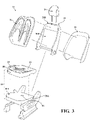
- Figure 3 shows an exploded view of the vehicle seat 16 of Figure 2 .
- the vehicle seat 16 includes a seat back 22 rotatably connected to a seat cushion 24 and a head restraint 26 coupled with the seat back 22.
- each of the seat cushion 24 and the seat back 22 includes a frame 28A, 28B for supporting a molded base foam pad 30A, 30B.
- the seat cushion 24 and optionally the seat back 22 are covered with molded ventilated trim cover assemblies 18, 20.
- the seat back 22 includes a seat back trim cover 32.
- Each ventilated trim cover assembly 18, 20 comprises a molded seat trim cover 36 optionally sewn or assembled with one or more side pieces 38 to form the trim cover assembly 18, 20.
- a seat cushion trim cover assembly 18 is assembled with the base foam pad 30A to form the seat cushion 24.
- the seat cushion trim cover assembly 18 and/or the seat back trim cover assembly 20 may include integrated ventilation as desired for a specific application.
- the present invention relates to molded ventilated seat trim covers 36 having an integrated airflow path for vehicle seats 16. More specifically, the disclosed molded ventilated seat trim covers 36 have an improved appearance, a reduction in required sew seams, releasable attachment to the vehicle seat, and improved breathability over traditional molded trim covers. Further, the disclosed molded ventilated seat trim covers 36 include an integrated airflow path eliminating the need for a plenum bag.
- FIG. 4 An embodiment of a FreeForm TM ventilated molded seat trim cover 36, shown in Figure 4 , illustrates molded features 40, molded lines 42 having the appearance of sew seams, surface concavity 44, and a 3-dimensional shape, according to one embodiment of the present invention.
- a cross-sectional view of the ventilated seat trim cover 36 is shown in Figure 5 .
- An enlarged portion of the cross-sectional view of the ventilated seat trim cover 36 of Figure 5 is shown in Figure 6 illustrating individual layers that make up the molded seat trim cover 36, according to one embodiment of the present invention.
- a ventilated seat cushion trim cover 36 is shown in Figures 4-6 , it will be appreciated that a ventilated seat back trim cover 20 can be similarly constructed as desired for an intended application.
- the seat trim cover 36 includes at least an upper textile layer 50 adhered to an upper side 52 of a moldable foam interlayer 54 with a thermoplastic polyurethane (TPU) film 56 adhered to a lower side 62 of the moldable foam interlayer 54, as shown in Figures 5 and 6 .
- the TPU film 56 is also described as a "TPU film layer" 56.
- a scrim backing layer 64 typically a woven or non-woven fabric, is adhered to a lower side 66 of the TPU film 56.
- the upper textile layer 50 comprises one or more of a fabric, perforated vinyl, and/or perforated leather.
- Adhesive layers 68, 70, 72 are shown between the upper textile layer 50, the foam interlayer 54, the TPU film 56, and the scrim backing layer 64.
- each seat trim cover 36 may have additional layers such as adhesives, spacer materials, and/or functional elements, such as embedded electronics, support brackets 76, attachment features, and/or seat heaters. It will be appreciated that a variety of materials can be incorporated into the seat trim cover 36 prior to compression molding as suitable or desired for an intended application.
- FIG. 7 illustrates airflow through the ventilated seat trim cover 36 according to one embodiment of the present invention.
- the foam interlayer 54 is air permeable.
- the TPU film layer 56 is air-impermeable and may have one or more passageways for passing airflow between the foam interlayer and an external environment adjacent a bottom surface of the ventilated trim cover.
- the one or more passageways in the TPU film are configured to direct airflow from or into the air channel in the base foam pad.
- the upper textile layer 50 is adhered to the foam interlayer 54 using flame lamination and/or an adhesive layer 68 such that airflow can pass from the foam interlayer 54, through the adhesive layer 68 (or flame lamination bond), and through the upper textile layer 50. While not shown in the Figures, optional perforations in the upper textile layer 50 may be uniformly distributed across the upper textile layer 50 and/or may be concentrated in selected locations allowing for directed airflow through the upper textile layer 50.
- a support bracket 76 including an air passageway 78 and an optional mounting flange 80 can be molded with the ventilated seat trim cover 36 during the compression molding process.
- the support bracket 76 illustrated in Figure 1A and 7 , can connect to an air channel 82 in the base foam pad 30A and/or can provide a connection for other components (not shown).
- the air passageway 78 fluidically connects with a passageway 84 in the TPU film 56 such that airflow through the passageway 78 can pass into the moldable foam interlayer 54.
- the TPU film 56 prevents airflow through the scrim backing layer 64. The airflow can travel along the foam interlayer 54 since the foam interlayer 54 is air permeable.
- the airflow passes between the foam interlayer 54 and the upper textile layer 50 and exits the seat trim cover 36. Further, while Figure 7 illustrates the airflow passing from the foam interlayer 54 through the upper textile layer 50, in selected applications the airflow direction can be reversed such that airflow passes through the upper textile layer 50 and enters the foam interlayer 54.
- FIGs 1A and 1B illustrate embodiments of the molded seat trim cover 36 assembled as part of a cooling seat cushion 24 and a ventilated seat cushion 24', respectively.
- the molded seat trim cover 36 includes the upper textile layer 50, the foam interlayer 54, the TPU film layer 56, and the scrim backing layer 64 as illustrated in the embodiment shown in Figure 7 .
- a support bracket 76 is assembled with the seat trim cover 36 during the compression-molding process to provide an air passageway 78 to the foam interlayer 54.
- the TPU film 56 includes one or more perforations and/or passageways 84 through the TPU film 56 to permit airflow through the TPU film 56 and into the foam interlayer 54.
- the molded seat trim cover 36 is assembled with additional side cover pieces 38 to form a trim cover assembly 18, as illustrated in Figure 1A .
- the seat trim cover 36 is preferably releasably attached to the foam base pad 30A.
- the foam base pad 30A includes at least one airflow channel 82 passing through the foam base pad 30A.
- a fan 94 is fluidly connected to the at least one airflow channel 82 to direct airflow through the airflow channel 82.
- the cooling seat cushion 24 includes a blower 96 with a thermoelectric device 98 to actively cool air up to about 10°C (about 18°F) below ambient vehicle air temperature.
- the blower 96 directs airflow through the airflow channel 82 and into the foam interlayer 54.
- the airflow travels through the foam interlayer 54 and exits the seat trim cover 36 through the upper textile layer 50.
- FIG. 1B illustrates a ventilated seat cushion 24'.
- the ventilated seat cushion 24' includes a fan 94 that pulls air down through an upper textile layer 50 and/or through perforations (not shown) in the upper textile layer 50, through a foam interlayer 54, and through an airflow channel 82 in a foam base pad 30A to reduce humidity and/or moisture within and/or on the ventilated seat cushion 24'.
- a fan 94 that pulls air down through an upper textile layer 50 and/or through perforations (not shown) in the upper textile layer 50, through a foam interlayer 54, and through an airflow channel 82 in a foam base pad 30A to reduce humidity and/or moisture within and/or on the ventilated seat cushion 24'.
- various embodiments of airflow paths towards and/or away from the foam interlayer 54 may vary, including configuration and placement of a fan 94, direction of airflow, as well as inclusion of additional features such as cooling and/or heating the upper textile layer 50 without altering the scope of the invention.
- Examples of known vehicle seat cushions 24A, 24B illustrating the use of a plenum bag 110 are shown in Figures 8A and 8B .
- the known vehicle seat cushion 24A shown in Figure 8A includes a cooling function and comprises a perforated leather upper textile layer 50A having cut-and-sew seams 50B, an air permeable spacer fabric (or foam) 112, an air-permeable foam pad 114, a plenum bag 110, a foam base pad 30C having at least one airflow channel 82A, and a blower 96A fluidly coupled to the at least one airflow channel 82A and having a thermoelectric device 98A to actively cool air up to about 10°C (about 18°F) below ambient vehicle air temperature.
- the upper textile layer 50A is part of a trim cover assembly 18A as shown in Figure 8A .
- the plenum bag 110 shown in Figure 8A comprises upper and lower layers 116, 118 of air-impermeable film 120 spaced apart by a spacer material 126.
- the two layers 116, 118 of air-impermeable film 120 have sealed edges (not shown) to form the plenum bag 110.
- the plenum bag 110 includes a port 128 for passing air between the plenum bag 110 and the airflow channel 82A in the base foam pad 30C.
- the upper layer 116 of the air-impermeable film 120 includes perforations (not shown) to direct airflow through the upper layer 116 of the plenum bag 110 and into the foam pad 114 above the plenum bag 110.
- the blower 96A forces airflow through the airflow channel 82A in the foam base pad 30C and towards the plenum bag 110. Airflow enters the plenum bag 110 through the port 128 travels along the plenum bag 110. Airflow passes through the perforations in the upper layer 116 of the plenum bag 110 and passes through the air-permeable foam pad 114, through the air-permeable spacer fabric 112, and through the perforations in the upper textile layer 50A.
- Figure 8B illustrates a known ventilated seat cushion 24B.
- the known ventilated seat cushion 24B includes similar components as shown in Figure 8A , i.e., a perforated leather upper textile layer 50A with cut-and-sew seams 50B, an air permeable spacer fabric (or foam) 112, an air-permeable foam pad 114, a plenum bag 110, and a foam base pad 30C having at least one airflow channel 82A.
- the known ventilated seat cushion 24B includes a fan 94A fluidically connected to the at least one airflow channel 82A in the foam base pad 30C.
- the fan 94A pulls airflow down through the leather upper textile layer 50A to reduce humidity and/or moisture near and/or adjacent the leather upper textile layer 50A.
- the fan 94A pulls airflow through perforations (not shown) in the leather upper textile layer 50A, through the air permeable spacer fabric 112, through the air permeable foam pad 114, through perforations (not shown) in an upper layer 116 of the plenum bag 110, through the interior of the plenum bag 110, through a port 128 in the plenum bag 110 and into the airflow channel 82A in the foam base pad 30C, and towards the fan 94A.
- the fan 94A exhausts the air away from the airflow channel 82A in the foam base pad 30C.
- the FreeForm TM seat trim covers can be used for ventilated seating applications incorporating a plenum bag 110.
- the FreeForm TM seat trim covers typically include at least an upper textile layer 50 laminated with a thermo-moldable foam interlayer 54 to form a laminate blank (not shown).
- the foam interlayer 54 is formulated to be moldable in a temperature range of about 104°C to about 127°C (about 220°F to about 260°F).
- the laminate blank is placed between 3-dimensional upper and lower mold tools (not shown).
- the upper and lower mold tools compress the laminate blank at a mold tool compressive pressure (i.e., compressive force) of about 150 psi to about 250 psi while the mold tools are heated to a temperature range of about 65°C to about 160°C (about 150°F to about 320°F).
- the FreeForm TM molded seat trim cover assemblies are suitable for use with a plenum bag 110 with the FreeForm TM molded seat trim cover assembly replacing the upper textile layer 50A, the air permeable spacer fabric (or foam) 112, and optionally, the air-permeable foam pad 114 shown in Figure 8A .
- the foam interlayer 54 allows for the elimination of the plenum bag 110 in a cooling and/or ventilated seat cushion 24, 24' if an air passageway 84 is incorporated in the TPU film 56.
- the disclosed FreeForm TM ventilated seat trim cover 36 eliminates the plenum bag 110 by incorporating an airflow path within the molded seat trim cover 36.
- the FreeForm TM ventilated seat trim cover 36 and the process for forming this ventilated seat trim cover 36, according to embodiments of the present disclosure, are described below and illustrated in Figures 9-18 .
- the molding process generally comprises the placing of the upper textile layer 50, the first adhesive layer 68, the moldable foam interlayer 54, the second adhesive layer 70, at least one layer to TPU film 56, the third adhesive layer 72, and a scrim backing layer 64 within a 3-dimensional mold tool 134 (shown in Figure 13A ) and compression molding the moldable foam interlayer 56 between 3-dimensional upper and lower mold tools 134A, 134B (shown in Figure 13A ).
- the foam interlayer 54 is formulated to be thermo-moldable in a temperature range of about 104°C to about 127°C (about 220°F to about 260°F) and is also air permeable.
- the 3-dimensional mold tools 134 are heated to a temperature range of about 65°C to about 160°C (about 150°F to about 320°F) to create a temperature gradient in the foam interlayer 54 during the compression molding process.
- a mold tool pressure of about 150 psi to about 250 psi is used to form the 3-dimensional shaped molded seat trim cover 36.
- the molded seat trim cover 36 is removed from the mold tool 134.
- the disclosed process may include more or less processing steps, as well as a different sequence of steps, as desired for a specific intended application or manufacturing process.
- individual layers can be inserted into the mold tool.
- one or more layers may be pre-assembled as a laminate blank and added to the mold tool along with additional individual layers.
- Additional components such as support brackets 76, sensors, heating circuits, and/or mounting hardware as non-limiting examples, can be inserted into the mold tools and/or between layers prior to compression molding the seat trim cover 36 to permanently adhere these components within and/or to the seat trim cover 36.
- vacuum assist can be added to the molding process if desired for an intended application.
- FIGS 9-13 One embodiment of this molding process is further illustrated in Figures 9-13 .
- an upper textile layer 50, a thermo-moldable air permeable foam interlayer 54, a TPU film layer 56, and a scrim backing layer 64 are optionally assembled to form a laminate blank 140, according to one embodiment of the present invention.
- a layer of adhesive 72 between the TPU film layer 56 and the scrim backing layer 64 is also shown.
- one or more of the upper textile layer 50, the moldable foam interlayer 54, the TPU film layer 56, and the scrim backing layer 64 can be precut into a desired blank shape 142 prior to assembling into the laminate blank 140, as shown in Figures 10 and 11 .
- the upper textile layer 50, the foam interlayer 54, and the scrim backing layer 64 can be described as a textile blank 50', a foam interlayer blank 54', and a scrim backing blank 64', respectively, when precut into a desired blank shape 142.
- the TPU film layer 56 can also be precut and may include holes for airflow.
- one or more of the upper textile layer 50, the moldable foam interlayer 54, the scrim backing layer 64, and additional layers such as TPU film 56 can be assembled and adhered into a laminated assembly 140 prior to cutting the laminate blank 142.
- Two or more layers of the laminate blank 140 can be assembled in sheet form and cut into the desired blank shape 142 after prebonding or pre-attaching the two or more layers. Gerber cutting is an exemplary process to pre-cut the layers into the blank shape 142 and/or cut the laminate blank 140 shape out of two or more assembled layers.
- FIG. 11 A perspective view of a laminate blank 140 comprising an upper textile layer 50, a foam interlayer 54, a TPU film 56, and a scrim backing layer 64 is illustrated in Figure 11 .
- the various layers 50, 54, 56, 64 in the laminate blank 140 are adhered and/or flame laminated to an adjacent layer 50, 54, 56, 64.
- laminate blank 140 may be included in the laminate blank 140 as desired for a particular application. Further, it will be appreciated that additional layers may be added to the laminate blank 140, such as a seat heater (not shown) or additional foam layers (not shown) having a different density, to form a quad-layer laminate or a multilayer laminate.
- the term "laminate blank" 140 describes two or more materials laminated together and cut into a desired blank shape 142. Thus, it will be appreciated that the laminate blank 140 may comprise more or less layers than illustrated in Figure 11 .
- the laminate blank 140 has a 2-dimensional shape, i.e. the laminate blank 140 is generally flat when resting unconstrained on a flat surface.
- the laminate blank 140 shape and size are configured so that minimal or no trimming is required after molding the seat trim cover 36 and prior to assembly with other components (not shown).
- An upper surface 148 of the upper textile layer 50 and a lower surface 150 of the scrim backing layer 64, as orientated and assembled into the laminate blank 140, are generally referred to as "A-surface” and "B-surface", respectively, of the molded seat trim cover 36.
- One or more adhesive layers 68, 70, 72 adhere the upper textile layer 50, the TPU film 56, and, optionally, the scrim backing layer 64 to the moldable foam interlayer 54 as illustrated in Figure 6 .
- the selection of an adhesive and/or adhesive method is based in part on the choice of materials for the upper textile layer 50 and the scrim backing layer 64.
- a variety of known adhesives such as thermoplastic adhesives, and one-part or two-part urethane adhesives (referred to as "1K” and "2K” adhesives), are suitable for adhesively bonding certain upper textile layers 50 and scrim backing layers 64 to the foam interlayer 54 and/or to the TPU film 56.
- Figures 12A -12C illustrate exemplary adhesive application patterns.
- the adhesive 68, 70, 72 can be applied by spraying, or can alternatively be a film or spider web-like pattern 146A (shown in Figure 12A ).
- One preferred method is applying adhesive to the upper textile layer 50 and/or the foam interlayer 54 in a spider web-like pattern 146A that is non-continuous.
- Other exemplary non-continuous adhesive application patterns include an array of dots 146B (shown in Figure 12B ) and an array of short segments 146C (shown in Figure 12C ). It will be appreciated that other adhesive application patterns may be selected, including irregular patterns, as suitable for an intended application, without varying the scope of the invention.
- various non-continuous patterns of adhesive 68, 70, 72 applications are suitable where airflow between adjacent layers is desired.
- thermoplastic adhesive can be roll-coated onto one or more surfaces to be bonded.
- gaps in adhesive coverage can be incorporated when applying adhesive to assure the bond between adjacent layers 50, 54, 56, 64 is air permeable.
- specific gaps can be included to provide openings for airflow, either when applying adhesive in a spider web-like pattern 146A or when applying adhesive by other methods.
- Thermoplastic adhesive can be remelted at elevated temperatures to separate the upper textile layer 50 from the foam interlayer 54, and then reassemble the upper textile layer 50 to the foam interlayer 54 to correct defects at any time during the manufacturing of the seat trim cover 36.
- Both 1K and 2K type adhesives have a delayed curing response and act like thermoplastic adhesive in the first 4 hours, permitting rebonding if needed.
- the 1K and 2K adhesives cure to a permanent bond within 24 hours.
- Both 1K and 2K adhesive systems eventually become thermosetting materials, so the bond between the layers 50, 54, 56, 64 becomes irreversible.
- the upper textile layer 50, the foam interlayer 54, the TPU film layer 56, and/or scrim backing layer 64 can be bonded to an adjacent layer by flame lamination.
- Flame lamination is a commonly known process to bond one or more layers of material to a foam interlayer 54 after passing the foam interlayer 54 past a flame to melt the surface of the foam interlayer 54. Flame lamination produces a permanent bond between the adjacent layers 50, 54, 56, 64.
- One or more of the adhesive layers 68, 70, 72 may be optionally replaced by flame lamination.
- the upper textile layer 50, the moldable foam interlayer 54, the TPU film layer 56, the optional scrim backing layer 64, and/or other material layers, as desired, may be adhered to one another with flame lamination such that one or more adhesive layers 68, 70, 72 are omitted between the adjacent layers 50, 54, 56, 64.
- two or more layers 50, 54, 56, 64 may be adhered by flame lamination prior to or after adhering one or more additional layers 50, 54, 56, 64 with adhesive if desired.
- adhesive type such as 1K or 2K urethane adhesives
- flame lamination is based in part on the selected upper textile layer 50 and the desired processing methods.
- certain materials are suitable for being adhered using flame lamination.
- Other materials may be more suitably bonded with a 1K or 2K urethane adhesive or other known adhesives.
- certain leathers may be unsuitable for being adhered to the moldable foam interlayer 54 using flame lamination.
- additional adhesive layers may be used when the laminate blank 140 includes more than three layers.
- individual layers may be adhered to an adjoining layer prior to or after cutting the layers into the blank shape 142.
- the TPU film layer 56 and the foam interlayer 54 may be bonded together using flame lamination or adhesive and then cut into a foam/TPU film blank (not shown).
- the foam/TPU film blank may be adhered to a pre-cut textile blank 50' using an adhesive or flame lamination.
- multiple layers 50, 54, 56, 64 may be stacked to form a stacked assembly 140 with one or more individual layers 50, 54, 56, 64 being unbonded until the stacked assembly 140 is compression molded.
- any combination of adhesive, flame lamination, bonding during the compression molding process, pre-cutting, and post-cutting, as well as material selection and number of layers, may be selected based on the desired finished ventilated seat trim cover 36 for a given application and/or preferred manufacturing method.
- TPU film 56 is a dual layer TPU film 154 (shown in Figure 15A ) having a low melt temperature TPU film layer 162 and a high melt temperature TPU film layer 164, also referred as "low-temp TPU” film layer 162 and "high-temp TPU” film layer 164, respectively.
- a preferred embodiment the low-temp TPU film layer 162 has a melting point in the temperature range of about 60°C to about 120°C (about 140°F to about 248°F).
- a preferred embodiment of the high-temp TPU film layer 164 has a melting point in the temperature range of about 120°C to about 150°C (about 248°F to about 302°F).
- the melting point of the low-temp and high-temp TPU film layers 162, 164 are selected such that the foam interlayer 54 can be flame laminated to the high-temp TPU film layer 164 without melting either of the low-temp TPU film layer 162 or the high-temp TPU film layer 164. Further, when a laminated sub-assembly 172 (shown in Figure 15A ) of the foam interlayer 54 flame laminated to the high-temp TPU film layer 164 is assembled with the scrim backing layer 64 (adjacent the low-temp TPU film layer 162), the low-temp TPU film layer 162 melts during the compression molding process to permanently bond the high-temp TPU film layer 164 to the scrim backing layer 64.
- a second embodiment of a dual layer TPU film 154' shown in Figure 16 , includes one or more openings 168 to allow for airflow through the dual layer TPU film 154', As with the first embodiment of the dual layer TPU film 154, the second embodiment of the dual layer TPU film 154' includes a low-temp TPU film layer 162' and a high-temp TPU film layer 164'.
- Certain upper textile layers 50 are prelaminated to a foam pad 176, referred to as a "plus foam pad” 176, forming a textile/plus pad sub-assembly 178, as shown in Figure 16 .
- the plus foam pad 176, of the textile/plus pad sub-assembly 178 can be flame laminated to a high-temp TPU film layer 164' of a dual layer TPU film 154', forming a textile / plus pad / dual layer TPU film sub-assembly 180.
- the dual layer TPU film 154' includes openings 168 for airflow into the plus foam pad 176 and the upper textile layer 50.
- a low-temp TPU film layer 162' of the dual layer TPU film 154' melts during the compression molding process to permanently bond the high-temp TPU film layer 164' to the foam interlayer 54.
- Suitable upper textile layers 50 include a variety of textiles, perforated vinyls, and perforated leathers.
- Exemplary textiles include polyester, polyester blends, acrylic blends, rayon, nylon, and similar fabrics.
- the selection of a textile 50 for a desired application depends on the amount of elongation in the lengthwise and the crosswise direction of the textile 50 in conjunction with the amount of forming required during the molding process.
- upper textile layers 50 having about 10% to about 25% elongation in both the lengthwise and crosswise directions have been found to be desirable.
- upper textile layers 50 with more or less elongation may be suitable depending on the desired 3-dimensional molded shape and the amount of concavity in the mold tools 134.
- the selected textile 50 can have a flat surface, a knap construction, and/or be woven or non-woven, depending on the desired appearance of the molded seat trim cover 36.
- textiles 50 can be laminated with foam materials, such as the plus foam pad 176, and/or spacer materials (not shown) to generate a desired appearance of the molded seat trim cover 36.
- a wide selection of upper textile layers 50 are suitable for use with the disclosed molding process since the preferred mold tool 134 temperature range, about 65°C to about 160°C (about 150°F to about 320°F), is below the distortion temperatures for a variety of fabrics. Certain fabrics are unsuitable for use in known prior art molding processes having molding temperatures in a range of about 148°C to about 249°C (about 300°F to about 480°F) since these fabrics may get distorted or damaged by the higher level of heat. Lowering the mold tool 134 temperature to a range of about 65°C to about 160°C (about 150°F to about 320°F) reduces and/or prevents fabric distortion during the molding process.
- the lower molding temperatures used in the disclosed process allows for an increase in obtainable contour of the 3-dimensional shape of the molded seat trim cover 36 without distorting or damaging the upper textile layer 50.
- Additional materials and/or laminate layers can be molded into a 3-dimensional shape by optionally adding vacuum assist and a removable barrier film (not shown) to the molding process, as will be described below.
- the moldable foam interlayer 54 underneath the upper textile layer 50 is used to achieve the desired final molded shape and to provide a soft and comfortable feel in the molded seat trim cover 36.
- the firmness, density, and thickness of the moldable foam interlayer 54 are selected to achieve a desired look or feel of the vehicle seat assembly 16.
- the moldable foam interlayer 54 is an air permeable open cell polyurethane (PU) foam formulated to be moldable at temperatures between about 104°C to about 127°C (about 220°F to about 260°F) as desired for an intended application.
- PU air permeable open cell polyurethane
- the glass transition temperature (Tg) of polyurethane foam is related to the upper limit of service temperature of the PU foam as well as the temperature at which the PU foam can be molded. Further, it is well known in the art that the Tg of a PU foam is affected by the foam chemistry, and in particular, the amount of cross-linking in the PU foam. Adding a graft polyol as well as adjusting diol content is one method of adjusting the Tg of PU foam.
- the Tg of PU foam can be controlled such that a selected moldable PU foam can be molded at temperatures between about 104°C to about 127°C (about 220°F to about 260°F) and still maintain support for the occupant and pass all applicable testing requirements, including life cycle, durability, and heat-aging.
- Typical PU foam formulations used in vehicle seating applications are generally moldable at temperatures greater than about 160°C (about 320°F). These foam formulations have previously been selected in order to ensure that vehicle seat assemblies 16 have acceptable performance over the life of a vehicle (not shown) and to permit short manufacturing cycle times.
- the PU foams with higher Tg values are difficult to mold and require expensive and/or complex molding methods.
- the high mold temperatures restrict options for the upper textile layers 50 because some textile materials are unsuitable for molding at temperatures above about 160°C (about 320°F).
- some of these known molding processes result in trim covers 18A having reduced breathability.
- the optional scrim backing blank 64' is illustrated in Figure 10 . As shown, the scrim backing layer 64 has been optionally pre-cut into the scrim blank 64' prior to assembly into the laminate blank 140. The scrim backing layer 64 improves the handling of the molded seat trim cover 36 when sewn to other components in an assembled trim cover 18. However, it will be appreciated that the scrim backing layer 64 may be omitted if desired.
- the scrim backing layer 64 may be a woven or non-woven fabric
- the elongation in the fibers of the scrim backing layer 64 impacts the formability of the laminate blank 140 during the molding process. Fabrics with greater elongation in the fibers are preferred over fabrics with less elongation in the fibers when molding highly-contoured molded seat trim covers 36. Further, selecting an upper textile layer 50 and scrim backing layer 64 having similar elongation in the fibers is preferred. Some common non-woven scrim backing layers 64 have suitable properties for both elongation and loop attachment behavior. Non-woven scrim backing layers 64 are inexpensive and pass typical warranty criteria, assembly criteria, and disassembly criteria.
- any suitable adhesive may be selected based on the desired manufacturing process and composition of the A-surface upper textile layer 50.
- adhesive layers 68, 70, 72 can be replaced with flame lamination as is generally known in the art. The selection of adhesive layer 68, 70, 72 or flame lamination, as well as the desired coverage of adhesive layers 68, 70, 72, is based on the intended application and preferred manufacturing methods. It will be appreciated that any combination and order of cutting, assembling, and adhering desired for an intended application can be selected.
- the laminate blank 140 can be incorporated into the laminate blank 140 than shown in the Figures. It will be appreciated that one or more sensors, electrical circuits, and/or alternate materials such as fiber batting and/or additional layers of foam can be incorporated into laminate blank 140 if desired. Also, while not specifically shown in the Figures, the A-surface upper textile layer 50 can comprise one or more pieces of material fastened together along a seam and/or layered together if desired.
- FIG. 13A illustrates a laminate blank 140 placed between upper and lower mold tools 134A, 134B. It will be appreciated that while the following description includes a laminate blank 140, individual layers may be inserted into the mold tool 134 without altering the scope of the invention.
- the upper and lower mold tools 134A, 134B have molding surfaces 190, 192 with a 3-dimensional shape, optionally one or more protrusions 194, and optionally one or more recessed areas 196.
- the upper and lower mold tools 134A, 134B can have different surface temperatures to be more compatible with various constructions of the upper textile layer 50 and foam interlayer 54.
- additional components may be inserted into the upper and/or lower mold tool 134A, 134B for mounting the molded seat trim cover 36 to the base foam pad 30A, providing connections to other components such as airflow channels 82, and/or including support brackets 76 in the molded seat trim cover 36.
- the support bracket 76 may include an air passageway 78 to pass airflow through the TPU film layer 56 and into the foam interlayer 54, as shown in Figure 7 . Further, the support bracket 76 may be configured to fluidically connect to an airflow channel 82 in the base foam pad 30A and/or connect to an alternate air supply port (not shown) in the vehicle seat 16.
- Figure 13B illustrates the laminate blank 140 compression molded to form the seat trim cover 36.
- the 3-dimensional shape is formed in a seat trim cover 36 by placing the laminate blank 140 between the upper 3-dimensionally shaped mold tool 134A and the lower 3-dimensionally shaped mold tool 134B, as generally illustrated in Figure 13A , compressing the laminate blank 140 between the upper and lower mold tools 134A, 134B with about 150 psi to about 250 psi pressure, and applying heat in a temperature range of about 65°C to about 160°C (about 150°F to about 320°F) to shape and compress the moldable foam interlayer 54, and removing the upper mold tool 134A from the molded seat trim cover 36 after a processing time of about 90 seconds to about 10 minutes.
- the amount of localized compression, as well as the formed induced surface contour results in a formed 3-dimensional seat trim cover 36 after molding which generally retains the desired 3-dimensional shape.
- the compression molding process may incorporate a vacuum assist step as desired for certain selected materials, thickness of the laminate blank 140, as well as the degree of contour in the upper and lower molding surfaces 134A, 134B. While not shown in the Figures, integrating vacuum assist as well as overall heating and/or spot heating into the upper and lower mold tools 134A, 134B is generally known to one skilled in the art of fabricating molding tools.
- the vacuum-form assist step can be performed before and/or during the compression molding step if desired.
- Improved appearance, increased 3-dimensional depth, and improved molded details can be obtained with certain materials, such a leather and/or thicker upper textile materials 50 or laminate blanks 140 with more than three layers, by adding vacuum assist during the molding process to partially or completely pre-form the laminate blank 140 against the upper or lower molding surface 134A, 134B.
- a barrier film (not shown) is placed on top of the laminate blank 140 after the laminate blank 140 is placed on the lower molding tool 134B. Vacuum is applied through the lower mold tool 134B to partially or fully form the laminate blank 140 to the lower mold tool 134B.
- the upper mold tool 134A is compressed against the barrier film and the laminate blank 140 and the upper and/or lower mold tools 134A, 134B are heated to a temperature of about 65°C to about 160°C (about 150°F to about 320°F) to shape and compress the moldable foam interlayer 54.
- the mold tools 134A, 134B may be uniformly heated. Alternatively, the mold tools 134A, 134B may have localized areas with increased heat temperature, as desired.
- the upper mold tool 134A is removed from the barrier film and molded seat trim cover 36.
- the seat trim cover 36 is removed from the lower molding tool 134B. Breathability of the molded seat trim cover 36 is generally retained since the barrier film is only used during the vacuum forming and compression molding processes, and removed from the molded seat trim cover 36 prior to assembling the molded seat trim cover 36 into a finished assembly 18. It will be appreciated that the disclosed process may include more or less processing steps, as well as a different sequence of steps, as desired for a specific application or manufacturing process.
- the selection of the molding temperature range and the location of zone heating in the mold tool 134 are based, in part, on the selected upper textile layer 50, the number of layers in the laminate blank 140, the selected mold design 134A, 134B, and the amount of concavity 44 and molding details 42 being formed in the molded trim cover 36.
- a mold temperature range of about 65°C to about 160°C (about 150°F to about 320°F) is desired. This will allow the foam interlayer 54 to be molded at a temperature range of about 104°C to about 127°C (about 220°F to about 260°F), producing acceptable molded seat trim covers 36 with machine cycle times from about 90 seconds to about 10 minutes depending on the forming aggressiveness and thickness of the laminate blank 140.
- Compression molding pressures of about 150 psi to about 250 psi are generally sufficient to produce satisfactory results. It will be appreciated that more or less molding pressure may be desired depending on a specific application, laminate blank 140 construction, machine configuration, and other factors such as machine cycle time.
- a pneumatic cylinder press is generally adequate to provide the desired amount of compression force during the molding process.
- Aluminum molding tools are generally suitable for the disclosed molding process since the desired molding temperature range is generally equal or less than about 165°C (about 320°F) and the molding pressures are generally equal or less than about 250 psi.
- the disclosed molding process does not require steel molding tools and/or hydraulic presses, and thus, the disclosed molding process can use lower cost mold tools 134 and lower cost machines than previously known molding methods for seat trim covers 36.
- the mold tools 134A, 134B can have self-contained heating systems (not shown) and can be adapted to have zonal heating as needed to facilitate more or less aggressive contours and styling lines. Vacuum assist can be integrated in the mold tools 134A, 134B when desired for a particular application and/or laminate blank 140 construction.
- Edges 36E of the seat molded trim cover 36, shown in Figure 4 are optionally trimmed and/or skived prior to assembling and/or sewing with other seat cover components 38 to form the finished trim cover assembly 18.
- the seat trim cover 36 is assembled into a final seat trim cover assembly 18 (by adding side components 38 and optional fasteners if needed), the seat trim cover assembly 18 is assembled on the base foam pad 30A to form the seat cushion 24 and/or seat back 22 of the vehicle seat 16, as illustrated in Figure 3 .
- the seat trim cover 36 is preferably releasably attached to the base foam pad 30A.
- the base foam pad 30A includes an air channel 82
- the seat trim cover 36 is aligned with the base foam pad 30A such that airflow through the air channel 82 can pass through the TPU film layer 56 of the seat trim cover 36 and into the foam interlayer 54.
- the seat trim cover 36 includes a support bracket 76 having a passageway 78 configured to pass airflow through a passageway 84 in the TPU film layer 56 and into the foam interlayer 54, the support bracket 76 is coupled with the air channel 82 in the base foam pad 30A.
- the base foam pad 30A provides the main support surface of a seating system as well as provides stability to maintain the contours of the overall vehicle seat 16 design.
- the base foam pad 30A does not require any design features when desired design features and styling lines are formed in molded "A-Surface" seat trim cover 36.
- a standardized base foam pad 30A can be used with many vehicle seat 16 designs when combined with a variety of seat trim cover 36 designs.
- Using a standardized base foam pad 30A reduces complexity in the foam manufacturing plants and seat assembly processes. There is a reduction in scrap and rework during the manufacturing process by including the design features in a removable seat trim cover 36 in combination with a simplified base foam pad 30A.
- a first embodiment of the seat trim cover 36 includes an upper textile layer 50, a first adhesive layer 68, a moldable air permeable foam interlayer 54, a second adhesive layer 70, a TPU film layer 56, a third adhesive layer 72, and a scrim backing layer 64.
- the upper textile layer 50 is a layer of fabric, perforated vinyl, and/or perforated leather.
- the upper textile layer 50 is bonded to the thermo-moldable foam interlayer 54 through adhesive bonding.
- the adhesive 68 is applied in a spider web-like pattern 146A that is non-continuous.
- the spider web-like pattern 146A allows air to flow freely between the foam interlayer 54 and the upper textile layer 50 and to pass through the fabric and/or perforations in the vinyl/leather.
- larger openings 202 can be created in the upper adhesive layer 68 to further direct airflow at preferred locations.
- the TPU film layer 56 is bonded to the foam interlayer 54 through adhesive bonding with the adhesive 70 applied in a spider web-like pattern 146A that is non-continuous. Applying the adhesive 70 in a spider web-like pattern 146A allows air to flow freely through the foam interlayer 54.
- the TPU film layer 56 is also bonded to a non-woven textile scrim backing layer 64 through adhesive bonding 72.
- the adhesive bond 72 can be applied either in a spider we-like pattern or as a solid film, as desired for a specific application.
- the TPU film layer 56 prevents airflow through the bottom of the seat trim cover 36.
- each of the layers 50, 54, 56, 64 shown in Figure 14A is optionally introduced separately into the compression molding process to form a stacked assembly 210.
- the scrim backing layer 64 can be placed on the lower mold tool 134B, a first adhesive layer 72 applied to the scrim backing layer 64, the TPU film layer 56 placed on top of the first adhesive layer 72, a second adhesive layer 70 applied to the TPU film layer 56, the thermo-moldable foam interlayer 54 placed on top of the second adhesive layer 70, a third adhesive layer 68 applied to the foam interlayer 54, the upper textile layer 50 placed on top of the third adhesive layer 68, followed by compression molding the resulting stacked assembly 210 as previously described.
- FIGs 15A and 15B illustrate a second embodiment of the seat trim cover 36 comprising an upper textile layer 50, a thermo-moldable foam interlayer 54, and a scrim backing layer 64 as in the first embodiment shown in Figures 14A and 14B .
- the TPU film layer 56 is replaced by a dual layer TPU film 154 having a low-temp TPU film layer 162 and a high-temp TPU film layer 164.
- a preferred embodiment of the low-temp and high-temp TPU film layers 162, 164 have melting points in the range of about 60°C to about 120°C (about 140°F to about 248°F) and about 120°C to about 150°C (about 240°F to about 302°F), respectively.
- the foam interlayer 54 is flame laminated to the high-temp TPU film layer 164 to form a foam/TPU film sub-assembly 172. Neither of the low-temp or the high-temp TPU film layers 162, 164 melt during the flame lamination process.
- the scrim backing layer 64 is placed on the lower compression mold tool 134B with the foam/TPU film sub-assembly 172 placed on top of the scrim backing layer 64.
- Adhesive 68 is applied in a spider web-like pattern 146A that is non-continuous to the foam interlayer 54 and/or to the upper textile layer 50. Applying adhesive in a spider web-like pattern 146A enables air to flow freely between the foam interlayer 54 and the upper textile layer 50. Larger openings 202 can be formed in the adhesive layer 68 to further direct airflow at preferred locations, as illustrated in Figure 15B .
- the upper textile layer 50 is assembled with the adhesive 68, the foam/TPU film sub-assembly 172, and the scrim backing layer 64 forming a layered stack 202A.
- the layered stack 202A is compression molded between the upper and lower mold tools 134A, 134B with about 150 psi to about 250 psi pressure while applying heat in a temperature range of about 65°C to about 160°C (about 150°F to about 320°F) to shape and compress the moldable foam interlayer 54.
- the low-temp TPU film layer 162 melts and bonds the high-temp TPU film layer 164 to the scrim backing layer 64.
- the high-temp TPU film layer 164 prevents airflow through the bottom of the molded seat trim cover 36.
- Figure 16 illustrates a third embodiment of the seat trim cover 36 comprising an upper textile layer 50, a thermo-moldable foam interlayer 54, and a scrim backing layer 64 similar to the embodiment shown in Figure 14A .
- the upper textile layer 50 is flame laminated and/or adhered to a plus foam pad 176 to form a textile/plus pad sub-assembly 178.
- the upper adhesive layer 68 shown in Figure 14A is replaced by a first dual layer TPU film 154' having a low-temp TPU film layer 162' and a high-temp TPU film layer 164' with melting points in the range of about 60°C to about 120°C (about 140°F to about 248°F) and about 120°C to about 150°C (about 240°F to about 302°F), respectively.
- the first dual layer TPU film 154' includes openings 168 for airflow.
- the plus foam pad 176 attached to the upper textile layer 50 is flame laminated to the high-temp TPU film layer 164' forming an upper textile/TPU sub-assembly 180.
- the upper textile/TPU sub-assembly 180, the foam interlayer/TPU film sub-assembly 214, and the scrim backing layer 64 are stacked on the lower compression mold tool 134B.
- both of the low-temp TPU film layers 162', 162 melt, bonding the respective high-temp TPU film layer 164', 164 to an adjacent layer 54, 64.
- the upper high-temp TPU film layer 164' is bonded to the foam interlayer 54 and the lower high-temp TPU film layer 164 is bonded to the scrim backing layer 64.
- the lower high-temp TPU film layer 164 prevents air flow through the bottom of the seat trim cover 36.
- the openings 168 in the upper high-temp TPU film layer 164' allow directed airflow between the foam interlayer 54 and the upper textile layer 50.
- Figure 17 illustrates a fourth embodiment of the seat trim cover 36 comprising an upper textile layer 50, a thermo-moldable foam interlayer 54, and a scrim backing layer 64 similar to the embodiment shown in Figure 14A .
- the upper textile layer 50 is flame laminated to the foam interlayer 54.
- a plus foam pad 176 is optionally adhered or flame laminated to the upper textile layer 50 if desired for a specific application. In the case when the upper textile layer 50 includes the plus foam pad 176, the plus foam pad 176 is flame laminated to the foam interlayer 54.
- the seat trim cover 36 includes a dual layer TPU film 154 including a low-temp TPU film layer 162 and a high-temp TPU film layer 164 with melting points in the range of about 60°C to about 120°C and about 120°C to about 150°C, respectively.
- the foam interlayer 54 is flame laminated to the high-temp TPU film layer 164 to form a textile / foam / TPU film tri-laminate sub-assembly 216.
- the textile/ foam/ TPU film tri-laminate sub-assembly 216 is stacked on the scrim backing layer 64 in the compression mold tool 134B.
- the low-temp TPU film layer 162 melts to bond the high-temp TPU film layer 164 to the scrim backing layer 64.
- the high-temp TPU film layer 164 prevents airflow through the bottom of the seat trim cover 36.
- Figure 18 illustrates a fifth embodiment of the seat trim cover 36 comprising an upper textile layer 50, a thermo-moldable foam interlayer 54, a TPU film layer 56, and a scrim backing layer 64 similar to the embodiment shown in Figure 14A .
- the upper textile layer 50 is flame laminated to the foam interlayer 54 to form a textile/foam sub-assembly 218.
- a plus foam pad 176 is optionally adhered or flame laminated to the upper textile layer 50 if desired for a specific application.
- the plus foam pad 176 is flame laminated to the foam interlayer 54 to form the textile/foam sub-assembly 218.
- the TPU film layer 56 is bonded to the foam interlayer 54 through adhesive bonding with a first adhesive layer 70 applied in a spider web-like pattern 146A that is non-continuous. Applying the adhesive 70 in a spider web-like pattern 146A allows air to flow freely through the foam interlayer 54.
- the TPU film layer 56 is also bonded to the scrim backing layer 64 through adhesive bonding 72.
- the second adhesive layer 72 can be applied either in a spider web-like pattern 146A or as a solid film, as desired for a specific application.
- the TPU film layer 56 prevents airflow through the bottom of the seat trim cover 36.
- the textile/foam sub-assembly 218 and each of the remaining layers 70, 56, 72, 64 shown in Figure 18 are introduced separately into the compression molding process.
- the scrim backing layer 64 can be placed on the lower mold tool 134B, a first adhesive layer 72 applied to the scrim backing layer 64, the TPU film layer 56 placed on top of the first adhesive layer 72, a second adhesive layer 70 applied to the TPU film layer 56, and the textile/foam sub-assembly 218 placed on top of the second adhesive layer 70, followed by compression molding the resulting stacked assembly 202C as previously described.
- the order of assembly of the various layers can be reversed without altering the scope of the invention.
- the upper textile layer 50 can be placed against the lower compression mold tool 134B with the scrim backing layer 64 positioned adjacent the upper compression mold tool 134A.
- the disclosed FreeForm TM ventilated trim covers manufactured using the FreeForm TM process have many benefits over other known methods of manufacturing trim covers.
- One benefit is the FreeForm TM ventilated molded trim covers have an integrated airflow path eliminating the need for a plenum bag in a ventilated vehicle seat.
- a second benefit is having a molded ventilated trim cover that is breathable in desired locations to enhance airflow.
- a third benefit is the amount of styling details, contours, and complexity in the trim cover can be increased over what is practical with the traditional cut-and-sew covers.
Landscapes
- Engineering & Computer Science (AREA)
- Mechanical Engineering (AREA)
- Aviation & Aerospace Engineering (AREA)
- Transportation (AREA)
- Textile Engineering (AREA)
- Physics & Mathematics (AREA)
- Fluid Mechanics (AREA)
- Laminated Bodies (AREA)
- Seats For Vehicles (AREA)
Description
- The present invention relates to a process for molding ventilated trim covers for vehicle seats and the ventilated trim covers formed using this molding process. More particularly, the invention relates to a process for forming 3-dimensional ventilated trim covers and vehicle seats having 3-dimensional ventilated trim covers.
- Automotive vehicles typically include one or more seat assemblies having a seat cushion and a seat back for supporting a passenger above a vehicle floor. Generally, each of the seat cushion and seat back comprise a base foam pad supported by a frame. A seat trim cover and optionally additional layers of foam and/or padding are assembled with the base foam pad to provide a finished surface. Each of the seat cushion and seat back generally have one or more contoured surfaces and generally require a contoured trim cover. The contoured cover generally comprises a seating surface portion (referred to hereafter as a trim cover panel or trim cover) fastened and/or sewn to one or more side pieces.
- Certain automotive seat assemblies include ventilation through the trim cover for occupant comfort. This ventilation can be combined with a forced air system as well as a heating and/or a cooling system depending on a desired vehicle seat configuration. The vehicle seat optionally includes a fan configured to force airflow through an airflow passageway in the base foam pad, through any intermediary layers of foam and/or padding, and through the trim cover. Alternatively, the fan draws air through the trim cover, through any intermediary layers of foam and/or padding, through the air passageway in the base foam pad, and towards the fan.
- One known ventilated vehicle seat cushion is disclosed in
U.S. Patent 8,820,829 . This known ventilated vehicle seat cushion is generally formed by adhering a fabric cover material to a carrier layer of open-pored cut foam, applying a barrier coat of polyurethane film in selected areas of the carrier layer, placing the assembly of the cover material, the carrier layer, and barrier coat within a foam forming tool, and filling the foam forming tool with reaction mixture to cold foam a main pad having airflow channels. When the seat cushion is assembled into a vehicle seat, airflow passes through the airflow channels in the pad, through holes in the barrier coat, into the carrier layer, and through the fabric cover material. While this method includes a molded seating surface, the seating surface is not removable from the main pad since the main pad is cold foamed with the cover material and the carrier layer. - Another commonly known ventilated vehicle seat is constructed using a plenum bag as described in
U.S. Patent 7,114,771 . The plenum bag generally comprises upper and lower layers of air-impermeable film with edges sealed forming a bag. This known ventilated seat comprises a perforated cover material assembled with an air-permeable foam layer, a plenum bag having air passageways to pass airflow between the plenum bag and the air-permeable foam layer, and a foam pad having an airflow passageway passing through the foam pad configured to pass airflow into the plenum bag. The plenum bag allows for the use of an assortment of methods of forming a trim cover for the vehicle seat since the trim cover is typically fastened, adhered, and otherwise assembled and/or formed with the foam pad. However, it is desirable to include the function of the plenum bag within a compression molded trim cover such that a separate plenum bag is not required. - A known compression molding process for forming trim covers, developed by Actex, Inc., is disclosed in
U.S. Patent 4,867,826 . The Actex method generally comprises the steps of applying a heat-curable urethane adhesive to one surface of a compressible polyurethane foam layer, directly contacting an upper textile material to the adhesive layer to form a bilayer, placing the bilayer on a platen, contacting the upper textile material layer of the bilayer with at least one heated projection of a mold tool at a temperature from about 150°C to about 250°C (about 300°F to about 480°F), compressing regions of the foam layer adjacent the heated projection while melting and collapsing the compressed regions of the foam layer using the heat of the projection to form permanent embossed lines in the bilayer. As well having limited amounts of molded surface contour, the Actex method lacks the function of a plenum bag within the finished trim cover. Further, the elevated molding temperatures required to melt and collapse compressed regions of the foam layer limit the selection of upper textile materials. - It is desirable, therefore, to form a molded ventilated trim cover for a vehicle seat with an integrated airflow path eliminating the need for a plenum bag. An additional benefit is having a molded ventilated trim cover that is breathable in desired locations to enhance air flow. Further, it is desirable to have a ventilated trim cover that is releasably fastened to a base foam pad since the seat trim cover can be interchanged as needed, without having to replace additional components of the vehicle seat. It is also desirable to form a trim cover utilizing a cellular polyurethane foam that is compression moldable in a temperature range of about 104°C to about 127°C (about 220°F to about 260°F), allowing for the use of an expanded range of cover materials. Finally, it is desirable to insert mold a plastic bracket and/or other attachment components within the finished trim cover to provide support to attach a fan and/or one or more air ducts.
- Document
US 2013/161998 discloses a cover S with a barrier film C that has holes (in film C and in the moulded part) to control air flow for a cover part of a ventilated seat. - A ventilated molded seat trim cover for a vehicle seat. Comprises a stacked assembly of an upper textile layer, a first adhesive layer, an air permeable polyurethane cellular foam interlayer thermo-moldable at temperatures between about 104°C and about 127°C, a second adhesive layer, a thermoplastic polyurethane (TPU) film, a third adhesive layer, and a scrim backing layer. The stacked assembly is compression molded in a 3-dimensional mold while at least a portion of the foam interlayer is heated to a temperature between about 104°C and about 127°C to form the ventilated molded seat trim cover. The TPU film prevents airflow passing through a bottom surface of the trim cover. Airflow in the foam interlayer can pass through the upper textile layer and towards an external environment above the trim cover.
- Advantages of the present invention will be readily appreciated as the same becomes better understood by reference to the following detailed description when considered in connection with the accompanying drawings wherein:
-
Figure 1A illustrates a cut-away perspective view of a vehicle seat having a molded ventilated seat trim cover with airflow exhausting through a seating surface, according to an embodiment of the present invention; -
Figure 1B illustrates a cut-away perspective view of a vehicle seat having a molded ventilated seat trim cover with airflow entering through a seating surface, according to another embodiment of the present invention; -
Figure 2 illustrates a perspective view of a vehicle seat having a molded ventilated seat cushion trim cover and a molded ventilated seat back trim cover, according to an embodiment of the present invention. -
Figure 3 illustrates an exploded view of the vehicle seat ofFigure 2 , according to an embodiment of the present invention; -
Figure 4 illustrates a top view of a molded ventilated seat trim cover according to an embodiment of the present invention; -
Figure 5 illustrates a cross-sectional view of the molded ventilated seat trim cover ofFigure 4 taken along section line 5-5 shown inFigure 4 , according to an embodiment of the present invention; -
Figure 6 illustrates an enlarged view of portion 6 of the cross-sectional view of the molded ventilated seat trim cover ofFigure 5 , according to an embodiment of the present invention; -
Figure 7 illustrates airflow through a portion of the ventilated seat trim cover ofFigure 4 , according to an embodiment of the present invention; -
Figure 8A illustrates a cut-away perspective view of a generally known vehicle seat having a plenum bag between a seat cover and a base foam pad with airflow exhausting through a seating surface; -
Figure 8B illustrates a cut-away perspective view of a generally known vehicle seat having a plenum bag between a seat cover and a base foam pad with airflow entering through a seating surface; -
Figure 9 illustrates a perspective view of layers forming the ventilated seat trim cover, according to an embodiment of the present invention; -
Figure 10 illustrates a top view of a cover material blank, a moldable foam interlayer blank, and a non-woven scrim backing blank, according to an embodiment of the present invention; -
Figure 11 illustrates a perspective view of a trilaminate assembly [laminate blank], according to an embodiment of the present invention; -
Figures 12A - 12C illustrate adhesive application patterns, according to embodiments of the present invention; -
Figure 13A illustrates a perspective view of the laminate blank ofFigure 11 inserted between a lower mold tool surface and an upper mold tool surface, according to an embodiment of the present invention; -
Figure 13B illustrates a perspective view of the laminate blank ofFigure 11 and the mold tools ofFigure 13A after a compression molding process, according to an embodiment of the present invention; -
Figures 14A and 14B illustrate a stacked assembly of an upper textile layer, a first adhesive layer, a foam interlayer, a second adhesive layer, a thermoplastic polyurethane (TPU) film, a third adhesive layer, and a scrim backing layer, according to one embodiment of the present invention; -
Figures 15A and 15B illustrate a stacked assembly of an upper textile layer, a first adhesive layer, a foam interlayer, a dual layer thermoplastic polyurethane (TPU) film, and a scrim backing layer, according to a second embodiment of the present invention; -
Figure 16 illustrates a stacked assembly of an upper textile layer, a plus pad, a first dual layer TPU film, a foam interlayer, a second dual layer TPU film, and a scrim backing layer, according to a third embodiment of the present invention; -
Figure 17 illustrates a stacked assembly of an upper textile layer, a foam interlayer, a dual layer TPU film, and a scrim backing layer, according to a fourth embodiment of the present invention; and -
Figure 18 illustrates a stacked assembly of an upper textile layer, a foam interlayer, a first adhesive layer, a TPU film, a second adhesive layer, and a scrim backing layer, according to a fifth embodiment of the present invention. -
Figures 1-7 and9-18 illustrate molded ventilated vehicle seat trim covers, vehicle seats having molded ventilated trim covers, and a process for manufacturing the ventilated seat trim covers according to embodiments described herein. Directional references employed or shown in the description, figures or claims, such as top, bottom, upper, lower, upward, downward, lengthwise, widthwise, left, right, and the like, are relative terms employed for ease of description and are not intended to limit the scope of the invention in any respect. Further, the Figures are not necessarily shown to scale. Referring to the Figures, like numerals indicate like or corresponding parts throughout the several views. -
Figures 1A and1B illustrate cut-away perspective views of a cooling vehicleseat cushion assembly 10 and a ventilated vehicleseat cushion assembly 12, respectively, having ventilated molded trim covers 14 according to embodiments of the present invention. Ventilated trim covers 14 assembled and compression-molded by way of a process disclosed herein are optionally described as FreeForm™ ventilated trim covers 14.Figure 2 shows a perspective view of avehicle seat assembly 16 having a ventilated seat cushiontrim cover assembly 18 and a ventilated seat backtrim cover assembly 20.Figure 3 shows an exploded view of thevehicle seat 16 ofFigure 2 . As shown inFigures 2 and3 , thevehicle seat 16 includes a seat back 22 rotatably connected to aseat cushion 24 and ahead restraint 26 coupled with the seat back 22. As shown inFigure 3 , each of theseat cushion 24 and the seat back 22 includes aframe base foam pad seat cushion 24 and optionally the seat back 22 are covered with molded ventilatedtrim cover assemblies trim cover 32. Each ventilatedtrim cover assembly trim cover 36 optionally sewn or assembled with one ormore side pieces 38 to form thetrim cover assembly Figure 1A , a seat cushiontrim cover assembly 18 is assembled with thebase foam pad 30A to form theseat cushion 24. The seat cushiontrim cover assembly 18 and/or the seat backtrim cover assembly 20 may include integrated ventilation as desired for a specific application. - The present invention relates to molded ventilated seat trim covers 36 having an integrated airflow path for vehicle seats 16. More specifically, the disclosed molded ventilated seat trim covers 36 have an improved appearance, a reduction in required sew seams, releasable attachment to the vehicle seat, and improved breathability over traditional molded trim covers. Further, the disclosed molded ventilated seat trim covers 36 include an integrated airflow path eliminating the need for a plenum bag.
- An embodiment of a FreeForm™ ventilated molded seat
trim cover 36, shown inFigure 4 , illustrates molded features 40, moldedlines 42 having the appearance of sew seams,surface concavity 44, and a 3-dimensional shape, according to one embodiment of the present invention. A cross-sectional view of the ventilated seattrim cover 36 is shown inFigure 5 . An enlarged portion of the cross-sectional view of the ventilated seattrim cover 36 ofFigure 5 is shown inFigure 6 illustrating individual layers that make up the molded seattrim cover 36, according to one embodiment of the present invention. While a ventilated seat cushiontrim cover 36 is shown inFigures 4-6 , it will be appreciated that a ventilated seat backtrim cover 20 can be similarly constructed as desired for an intended application. - The seat trim
cover 36 includes at least anupper textile layer 50 adhered to anupper side 52 of amoldable foam interlayer 54 with a thermoplastic polyurethane (TPU)film 56 adhered to alower side 62 of themoldable foam interlayer 54, as shown inFigures 5 and6 . TheTPU film 56 is also described as a "TPU film layer" 56. Ascrim backing layer 64, typically a woven or non-woven fabric, is adhered to alower side 66 of theTPU film 56. Theupper textile layer 50 comprises one or more of a fabric, perforated vinyl, and/or perforated leather. Adhesive layers 68, 70, 72 are shown between theupper textile layer 50, thefoam interlayer 54, theTPU film 56, and thescrim backing layer 64. Optionally, while not shown inFigure 6 , each seat trimcover 36 may have additional layers such as adhesives, spacer materials, and/or functional elements, such as embedded electronics,support brackets 76, attachment features, and/or seat heaters. It will be appreciated that a variety of materials can be incorporated into the seattrim cover 36 prior to compression molding as suitable or desired for an intended application. -
Figure 7 illustrates airflow through the ventilated seattrim cover 36 according to one embodiment of the present invention. Thefoam interlayer 54 is air permeable. TheTPU film layer 56 is air-impermeable and may have one or more passageways for passing airflow between the foam interlayer and an external environment adjacent a bottom surface of the ventilated trim cover. When assembled with a base foam pad having an air channel, the one or more passageways in the TPU film are configured to direct airflow from or into the air channel in the base foam pad. In this embodiment, theupper textile layer 50 is adhered to thefoam interlayer 54 using flame lamination and/or anadhesive layer 68 such that airflow can pass from thefoam interlayer 54, through the adhesive layer 68 (or flame lamination bond), and through theupper textile layer 50. While not shown in the Figures, optional perforations in theupper textile layer 50 may be uniformly distributed across theupper textile layer 50 and/or may be concentrated in selected locations allowing for directed airflow through theupper textile layer 50. - A
support bracket 76 including anair passageway 78 and an optional mountingflange 80 can be molded with the ventilated seattrim cover 36 during the compression molding process. Thesupport bracket 76, illustrated inFigure 1A and7 , can connect to anair channel 82 in thebase foam pad 30A and/or can provide a connection for other components (not shown). Theair passageway 78 fluidically connects with apassageway 84 in theTPU film 56 such that airflow through thepassageway 78 can pass into themoldable foam interlayer 54. TheTPU film 56 prevents airflow through thescrim backing layer 64. The airflow can travel along thefoam interlayer 54 since thefoam interlayer 54 is air permeable. As shown inFigure 7 , the airflow passes between thefoam interlayer 54 and theupper textile layer 50 and exits the seattrim cover 36. Further, whileFigure 7 illustrates the airflow passing from thefoam interlayer 54 through theupper textile layer 50, in selected applications the airflow direction can be reversed such that airflow passes through theupper textile layer 50 and enters thefoam interlayer 54. -
Figures 1A and1B illustrate embodiments of the molded seattrim cover 36 assembled as part of a coolingseat cushion 24 and a ventilated seat cushion 24', respectively. The molded seattrim cover 36 includes theupper textile layer 50, thefoam interlayer 54, theTPU film layer 56, and thescrim backing layer 64 as illustrated in the embodiment shown inFigure 7 . Optionally, asupport bracket 76 is assembled with the seattrim cover 36 during the compression-molding process to provide anair passageway 78 to thefoam interlayer 54. Further, as shown inFigure 7 , theTPU film 56 includes one or more perforations and/orpassageways 84 through theTPU film 56 to permit airflow through theTPU film 56 and into thefoam interlayer 54. - The molded seat
trim cover 36 is assembled with additionalside cover pieces 38 to form atrim cover assembly 18, as illustrated inFigure 1A . The seat trimcover 36 is preferably releasably attached to thefoam base pad 30A. Thefoam base pad 30A includes at least oneairflow channel 82 passing through thefoam base pad 30A. Afan 94 is fluidly connected to the at least oneairflow channel 82 to direct airflow through theairflow channel 82. In the embodiment shown inFigure 1A , the coolingseat cushion 24 includes a blower 96 with athermoelectric device 98 to actively cool air up to about 10°C (about 18°F) below ambient vehicle air temperature. The blower 96 directs airflow through theairflow channel 82 and into thefoam interlayer 54. The airflow travels through thefoam interlayer 54 and exits the seattrim cover 36 through theupper textile layer 50. - The embodiment shown in
Figure 1B is similar to the embodiment shown inFigure 1A .Figure 1B illustrates a ventilated seat cushion 24'. The ventilated seat cushion 24' includes afan 94 that pulls air down through anupper textile layer 50 and/or through perforations (not shown) in theupper textile layer 50, through afoam interlayer 54, and through anairflow channel 82 in afoam base pad 30A to reduce humidity and/or moisture within and/or on the ventilated seat cushion 24'. It will be appreciated that various embodiments of airflow paths towards and/or away from thefoam interlayer 54 may vary, including configuration and placement of afan 94, direction of airflow, as well as inclusion of additional features such as cooling and/or heating theupper textile layer 50 without altering the scope of the invention. - Both of the cooling
seat cushion 24 and the ventilated seat cushion 24' configurations, illustrated inFigures 1A and1B , respectively, lack aplenum bag 110. Examples of known vehicle seat cushions 24A, 24B illustrating the use of aplenum bag 110 are shown inFigures 8A and8B . The knownvehicle seat cushion 24A shown inFigure 8A includes a cooling function and comprises a perforated leatherupper textile layer 50A having cut-and-sewseams 50B, an air permeable spacer fabric (or foam) 112, an air-permeable foam pad 114, aplenum bag 110, afoam base pad 30C having at least oneairflow channel 82A, and ablower 96A fluidly coupled to the at least oneairflow channel 82A and having athermoelectric device 98A to actively cool air up to about 10°C (about 18°F) below ambient vehicle air temperature. Theupper textile layer 50A is part of atrim cover assembly 18A as shown inFigure 8A . - The
plenum bag 110 shown inFigure 8A comprises upper andlower layers impermeable film 120 spaced apart by aspacer material 126. The twolayers impermeable film 120 have sealed edges (not shown) to form theplenum bag 110. Theplenum bag 110 includes aport 128 for passing air between theplenum bag 110 and theairflow channel 82A in thebase foam pad 30C. Theupper layer 116 of the air-impermeable film 120 includes perforations (not shown) to direct airflow through theupper layer 116 of theplenum bag 110 and into thefoam pad 114 above theplenum bag 110. InFigure 8A , theblower 96A forces airflow through theairflow channel 82A in thefoam base pad 30C and towards theplenum bag 110. Airflow enters theplenum bag 110 through theport 128 travels along theplenum bag 110. Airflow passes through the perforations in theupper layer 116 of theplenum bag 110 and passes through the air-permeable foam pad 114, through the air-permeable spacer fabric 112, and through the perforations in theupper textile layer 50A. - In contrast to
Figure 8A ,Figure 8B illustrates a known ventilatedseat cushion 24B. The known ventilatedseat cushion 24B includes similar components as shown inFigure 8A , i.e., a perforated leatherupper textile layer 50A with cut-and-sewseams 50B, an air permeable spacer fabric (or foam) 112, an air-permeable foam pad 114, aplenum bag 110, and afoam base pad 30C having at least oneairflow channel 82A. The known ventilatedseat cushion 24B includes afan 94A fluidically connected to the at least oneairflow channel 82A in thefoam base pad 30C. Thefan 94A pulls airflow down through the leatherupper textile layer 50A to reduce humidity and/or moisture near and/or adjacent the leatherupper textile layer 50A. Thefan 94A pulls airflow through perforations (not shown) in the leatherupper textile layer 50A, through the airpermeable spacer fabric 112, through the airpermeable foam pad 114, through perforations (not shown) in anupper layer 116 of theplenum bag 110, through the interior of theplenum bag 110, through aport 128 in theplenum bag 110 and into theairflow channel 82A in thefoam base pad 30C, and towards thefan 94A. Thefan 94A exhausts the air away from theairflow channel 82A in thefoam base pad 30C. - However, both these known vehicle
seat cushion configurations Figures 8A and8B , respectively, require aplenum bag 110 to distribute airflow between theairflow channel 82A in thefoam base pad 30C and the airpermeable foam pad 114, the airpermeable spacer fabric 112, and theupper textile layer 50A. - While not shown in the Figures, seat trim covers produced using the FreeForm™ process described in W.O. application
PCT/US2019/035244 , can be used for ventilated seating applications incorporating aplenum bag 110. The FreeForm™ seat trim covers typically include at least anupper textile layer 50 laminated with a thermo-moldable foam interlayer 54 to form a laminate blank (not shown). Thefoam interlayer 54 is formulated to be moldable in a temperature range of about 104°C to about 127°C (about 220°F to about 260°F). The laminate blank is placed between 3-dimensional upper and lower mold tools (not shown). The upper and lower mold tools compress the laminate blank at a mold tool compressive pressure (i.e., compressive force) of about 150 psi to about 250 psi while the mold tools are heated to a temperature range of about 65°C to about 160°C (about 150°F to about 320°F). The FreeForm™ molded seat trim cover assemblies are suitable for use with aplenum bag 110 with the FreeForm™ molded seat trim cover assembly replacing theupper textile layer 50A, the air permeable spacer fabric (or foam) 112, and optionally, the air-permeable foam pad 114 shown inFigure 8A . - However, including air-
impermeable TPU film 56 adjacent and in contact with thefoam interlayer 54 prior to compression molding thefoam interlayer 54 allows for the elimination of theplenum bag 110 in a cooling and/or ventilatedseat cushion 24, 24' if anair passageway 84 is incorporated in theTPU film 56. The disclosed FreeForm™ ventilated seattrim cover 36 eliminates theplenum bag 110 by incorporating an airflow path within the molded seattrim cover 36. The FreeForm™ ventilated seattrim cover 36 and the process for forming this ventilated seattrim cover 36, according to embodiments of the present disclosure, are described below and illustrated inFigures 9-18 . - While embodiments described below include variations in the composition of layers in the ventilated seat
trim cover 36, the molding process generally comprises the placing of theupper textile layer 50, the firstadhesive layer 68, themoldable foam interlayer 54, the secondadhesive layer 70, at least one layer toTPU film 56, the thirdadhesive layer 72, and ascrim backing layer 64 within a 3-dimensional mold tool 134 (shown inFigure 13A ) and compression molding themoldable foam interlayer 56 between 3-dimensional upper andlower mold tools Figure 13A ). Thefoam interlayer 54 is formulated to be thermo-moldable in a temperature range of about 104°C to about 127°C (about 220°F to about 260°F) and is also air permeable. The 3-dimensional mold tools 134 are heated to a temperature range of about 65°C to about 160°C (about 150°F to about 320°F) to create a temperature gradient in thefoam interlayer 54 during the compression molding process. A mold tool pressure of about 150 psi to about 250 psi is used to form the 3-dimensional shaped molded seattrim cover 36. After the compression molding process is complete, the molded seattrim cover 36 is removed from themold tool 134. - It will be appreciated that the disclosed process may include more or less processing steps, as well as a different sequence of steps, as desired for a specific intended application or manufacturing process. Alternatively, individual layers can be inserted into the mold tool. Further, one or more layers may be pre-assembled as a laminate blank and added to the mold tool along with additional individual layers. Additional components, such as
support brackets 76, sensors, heating circuits, and/or mounting hardware as non-limiting examples, can be inserted into the mold tools and/or between layers prior to compression molding the seattrim cover 36 to permanently adhere these components within and/or to the seattrim cover 36. In addition, it will be appreciated that vacuum assist can be added to the molding process if desired for an intended application. - One embodiment of this molding process is further illustrated in
Figures 9-13 . Referring toFigure 9 , anupper textile layer 50, a thermo-moldable airpermeable foam interlayer 54, aTPU film layer 56, and ascrim backing layer 64 are optionally assembled to form a laminate blank 140, according to one embodiment of the present invention. Also shown is a layer of adhesive 72 between theTPU film layer 56 and thescrim backing layer 64. Further, it will be appreciated that one or more of theupper textile layer 50, themoldable foam interlayer 54, theTPU film layer 56, and thescrim backing layer 64 can be precut into a desiredblank shape 142 prior to assembling into the laminate blank 140, as shown inFigures 10 and 11 . Theupper textile layer 50, thefoam interlayer 54, and thescrim backing layer 64 can be described as a textile blank 50', a foam interlayer blank 54', and a scrim backing blank 64', respectively, when precut into a desiredblank shape 142. While not shown, theTPU film layer 56 can also be precut and may include holes for airflow. Alternatively, one or more of theupper textile layer 50, themoldable foam interlayer 54, thescrim backing layer 64, and additional layers such asTPU film 56, can be assembled and adhered into alaminated assembly 140 prior to cutting the laminate blank 142. Two or more layers of the laminate blank 140 can be assembled in sheet form and cut into the desiredblank shape 142 after prebonding or pre-attaching the two or more layers. Gerber cutting is an exemplary process to pre-cut the layers into theblank shape 142 and/or cut the laminate blank 140 shape out of two or more assembled layers. - A perspective view of a laminate blank 140 comprising an
upper textile layer 50, afoam interlayer 54, aTPU film 56, and ascrim backing layer 64 is illustrated inFigure 11 . Thevarious layers adjacent layer - It will be appreciated that more or less layers may be included in the laminate blank 140 as desired for a particular application. Further, it will be appreciated that additional layers may be added to the laminate blank 140, such as a seat heater (not shown) or additional foam layers (not shown) having a different density, to form a quad-layer laminate or a multilayer laminate. The term "laminate blank" 140 describes two or more materials laminated together and cut into a desired
blank shape 142. Thus, it will be appreciated that the laminate blank 140 may comprise more or less layers than illustrated inFigure 11 . - Generally, as shown in
Figure 11 , the laminate blank 140 has a 2-dimensional shape, i.e. the laminate blank 140 is generally flat when resting unconstrained on a flat surface. Preferably, the laminate blank 140 shape and size are configured so that minimal or no trimming is required after molding the seattrim cover 36 and prior to assembly with other components (not shown). Anupper surface 148 of theupper textile layer 50 and alower surface 150 of thescrim backing layer 64, as orientated and assembled into the laminate blank 140, are generally referred to as "A-surface" and "B-surface", respectively, of the molded seattrim cover 36. - One or more
adhesive layers upper textile layer 50, theTPU film 56, and, optionally, thescrim backing layer 64 to themoldable foam interlayer 54 as illustrated inFigure 6 . The selection of an adhesive and/or adhesive method is based in part on the choice of materials for theupper textile layer 50 and thescrim backing layer 64. A variety of known adhesives, such as thermoplastic adhesives, and one-part or two-part urethane adhesives (referred to as "1K" and "2K" adhesives), are suitable for adhesively bonding certain upper textile layers 50 and scrim backing layers 64 to thefoam interlayer 54 and/or to theTPU film 56.Figures 12A -12C illustrate exemplary adhesive application patterns. The adhesive 68, 70, 72 can be applied by spraying, or can alternatively be a film or spider web-like pattern 146A (shown inFigure 12A ). One preferred method is applying adhesive to theupper textile layer 50 and/or thefoam interlayer 54 in a spider web-like pattern 146A that is non-continuous. Other exemplary non-continuous adhesive application patterns include an array ofdots 146B (shown inFigure 12B ) and an array of short segments 146C (shown inFigure 12C ). It will be appreciated that other adhesive application patterns may be selected, including irregular patterns, as suitable for an intended application, without varying the scope of the invention. Generally, various non-continuous patterns of adhesive 68, 70, 72 applications are suitable where airflow between adjacent layers is desired. Further, thermoplastic adhesive can be roll-coated onto one or more surfaces to be bonded. Alternatively, gaps in adhesive coverage can be incorporated when applying adhesive to assure the bond betweenadjacent layers - Thermoplastic adhesive can be remelted at elevated temperatures to separate the
upper textile layer 50 from thefoam interlayer 54, and then reassemble theupper textile layer 50 to thefoam interlayer 54 to correct defects at any time during the manufacturing of the seattrim cover 36. Both 1K and 2K type adhesives have a delayed curing response and act like thermoplastic adhesive in the first 4 hours, permitting rebonding if needed. The 1K and 2K adhesives cure to a permanent bond within 24 hours. Both 1K and 2K adhesive systems eventually become thermosetting materials, so the bond between thelayers - As an alternative to adhesive, the
upper textile layer 50, thefoam interlayer 54, theTPU film layer 56, and/orscrim backing layer 64 can be bonded to an adjacent layer by flame lamination. Flame lamination is a commonly known process to bond one or more layers of material to afoam interlayer 54 after passing thefoam interlayer 54 past a flame to melt the surface of thefoam interlayer 54. Flame lamination produces a permanent bond between theadjacent layers adhesive layers upper textile layer 50, themoldable foam interlayer 54, theTPU film layer 56, the optionalscrim backing layer 64, and/or other material layers, as desired, may be adhered to one another with flame lamination such that one or moreadhesive layers adjacent layers - Additionally, two or
more layers additional layers upper textile layer 50 and the desired processing methods. As is generally well known to those skilled in the art, certain materials are suitable for being adhered using flame lamination. Other materials may be more suitably bonded with a 1K or 2K urethane adhesive or other known adhesives. For example, certain leathers may be unsuitable for being adhered to themoldable foam interlayer 54 using flame lamination. - Further, additional adhesive layers may be used when the laminate blank 140 includes more than three layers. Also, individual layers may be adhered to an adjoining layer prior to or after cutting the layers into the
blank shape 142. For example, theTPU film layer 56 and thefoam interlayer 54 may be bonded together using flame lamination or adhesive and then cut into a foam/TPU film blank (not shown). The foam/TPU film blank may be adhered to a pre-cut textile blank 50' using an adhesive or flame lamination. Alternatively,multiple layers stacked assembly 140 with one or moreindividual layers stacked assembly 140 is compression molded. It will be appreciated that any combination of adhesive, flame lamination, bonding during the compression molding process, pre-cutting, and post-cutting, as well as material selection and number of layers, may be selected based on the desired finished ventilated seattrim cover 36 for a given application and/or preferred manufacturing method. - Another embodiment of the
TPU film 56 is a dual layer TPU film 154 (shown inFigure 15A ) having a low melt temperatureTPU film layer 162 and a high melt temperatureTPU film layer 164, also referred as "low-temp TPU"film layer 162 and "high-temp TPU"film layer 164, respectively. A preferred embodiment the low-tempTPU film layer 162 has a melting point in the temperature range of about 60°C to about 120°C (about 140°F to about 248°F). A preferred embodiment of the high-tempTPU film layer 164 has a melting point in the temperature range of about 120°C to about 150°C (about 248°F to about 302°F). The melting point of the low-temp and high-temp TPU film layers 162, 164 are selected such that thefoam interlayer 54 can be flame laminated to the high-tempTPU film layer 164 without melting either of the low-tempTPU film layer 162 or the high-tempTPU film layer 164. Further, when a laminated sub-assembly 172 (shown inFigure 15A ) of thefoam interlayer 54 flame laminated to the high-tempTPU film layer 164 is assembled with the scrim backing layer 64 (adjacent the low-temp TPU film layer 162), the low-tempTPU film layer 162 melts during the compression molding process to permanently bond the high-tempTPU film layer 164 to thescrim backing layer 64. - A second embodiment of a dual layer TPU film 154', shown in
Figure 16 , includes one ormore openings 168 to allow for airflow through the dual layer TPU film 154', As with the first embodiment of the duallayer TPU film 154, the second embodiment of the dual layer TPU film 154' includes a low-temp TPU film layer 162' and a high-temp TPU film layer 164'. - Certain upper textile layers 50 are prelaminated to a
foam pad 176, referred to as a "plus foam pad" 176, forming a textile/plus pad sub-assembly 178, as shown inFigure 16 . Theplus foam pad 176, of the textile/plus pad sub-assembly 178, can be flame laminated to a high-temp TPU film layer 164' of a dual layer TPU film 154', forming a textile / plus pad / dual layerTPU film sub-assembly 180. In this case, the dual layer TPU film 154' includesopenings 168 for airflow into theplus foam pad 176 and theupper textile layer 50. When textile / plus pad / dual layerTPU film sub-assembly 180 is stacked adjacent thefoam interlayer 54 in the lowercompression mold tool 134B, a low-temp TPU film layer 162' of the dual layer TPU film 154' melts during the compression molding process to permanently bond the high-temp TPU film layer 164' to thefoam interlayer 54. - Suitable upper textile layers 50 include a variety of textiles, perforated vinyls, and perforated leathers. Exemplary textiles include polyester, polyester blends, acrylic blends, rayon, nylon, and similar fabrics. The selection of a
textile 50 for a desired application depends on the amount of elongation in the lengthwise and the crosswise direction of the textile 50 in conjunction with the amount of forming required during the molding process. Generally, upper textile layers 50 having about 10% to about 25% elongation in both the lengthwise and crosswise directions have been found to be desirable. However, upper textile layers 50 with more or less elongation may be suitable depending on the desired 3-dimensional molded shape and the amount of concavity in themold tools 134. The selectedtextile 50 can have a flat surface, a knap construction, and/or be woven or non-woven, depending on the desired appearance of the molded seattrim cover 36. Optionally,textiles 50 can be laminated with foam materials, such as theplus foam pad 176, and/or spacer materials (not shown) to generate a desired appearance of the molded seattrim cover 36. - A wide selection of upper textile layers 50 are suitable for use with the disclosed molding process since the
preferred mold tool 134 temperature range, about 65°C to about 160°C (about 150°F to about 320°F), is below the distortion temperatures for a variety of fabrics. Certain fabrics are unsuitable for use in known prior art molding processes having molding temperatures in a range of about 148°C to about 249°C (about 300°F to about 480°F) since these fabrics may get distorted or damaged by the higher level of heat. Lowering themold tool 134 temperature to a range of about 65°C to about 160°C (about 150°F to about 320°F) reduces and/or prevents fabric distortion during the molding process. Further, the lower molding temperatures used in the disclosed process allows for an increase in obtainable contour of the 3-dimensional shape of the molded seattrim cover 36 without distorting or damaging theupper textile layer 50. Additional materials and/or laminate layers can be molded into a 3-dimensional shape by optionally adding vacuum assist and a removable barrier film (not shown) to the molding process, as will be described below. - The
moldable foam interlayer 54 underneath theupper textile layer 50 is used to achieve the desired final molded shape and to provide a soft and comfortable feel in the molded seattrim cover 36. The firmness, density, and thickness of themoldable foam interlayer 54 are selected to achieve a desired look or feel of thevehicle seat assembly 16. Themoldable foam interlayer 54 is an air permeable open cell polyurethane (PU) foam formulated to be moldable at temperatures between about 104°C to about 127°C (about 220°F to about 260°F) as desired for an intended application. - As is generally known in the art of manufacturing polyurethane foams, the glass transition temperature (Tg) of polyurethane foam is related to the upper limit of service temperature of the PU foam as well as the temperature at which the PU foam can be molded. Further, it is well known in the art that the Tg of a PU foam is affected by the foam chemistry, and in particular, the amount of cross-linking in the PU foam. Adding a graft polyol as well as adjusting diol content is one method of adjusting the Tg of PU foam. The Tg of PU foam can be controlled such that a selected moldable PU foam can be molded at temperatures between about 104°C to about 127°C (about 220°F to about 260°F) and still maintain support for the occupant and pass all applicable testing requirements, including life cycle, durability, and heat-aging.
- Typical PU foam formulations used in vehicle seating applications are generally moldable at temperatures greater than about 160°C (about 320°F). These foam formulations have previously been selected in order to ensure that
vehicle seat assemblies 16 have acceptable performance over the life of a vehicle (not shown) and to permit short manufacturing cycle times. However, the PU foams with higher Tg values are difficult to mold and require expensive and/or complex molding methods. Further, the high mold temperatures restrict options for the upper textile layers 50 because some textile materials are unsuitable for molding at temperatures above about 160°C (about 320°F). In addition, some of these known molding processes result in trim covers 18A having reduced breathability. - It has been found that by reducing the Tg in moldable PU foam, satisfactory results can be obtained by molding seat trim covers 36 with a foam molding temperature of about 104°C to about 127°C (about 220°F to about 260°F), as disclosed in the present invention. Further, since the foam molding temperature is about 127°C (about 260°F) or less, the cost and complexity of the
mold tools 134 is reduced and the range of suitable upper textile layers 50 is increased. - The optional scrim backing blank 64' is illustrated in
Figure 10 . As shown, thescrim backing layer 64 has been optionally pre-cut into the scrim blank 64' prior to assembly into the laminate blank 140. Thescrim backing layer 64 improves the handling of the molded seattrim cover 36 when sewn to other components in an assembledtrim cover 18. However, it will be appreciated that thescrim backing layer 64 may be omitted if desired. - While the
scrim backing layer 64 may be a woven or non-woven fabric, the elongation in the fibers of thescrim backing layer 64 impacts the formability of the laminate blank 140 during the molding process. Fabrics with greater elongation in the fibers are preferred over fabrics with less elongation in the fibers when molding highly-contoured molded seat trim covers 36. Further, selecting anupper textile layer 50 andscrim backing layer 64 having similar elongation in the fibers is preferred. Some common non-woven scrim backing layers 64 have suitable properties for both elongation and loop attachment behavior. Non-woven scrim backing layers 64 are inexpensive and pass typical warranty criteria, assembly criteria, and disassembly criteria. - It will be appreciated that the individual layers, shown in
Figure 6 andFigures 14A-18 , can be assembled in any order suitable for an intended application and desired manufacturing process. Further, it will be appreciated that any suitable adhesive may be selected based on the desired manufacturing process and composition of the A-surfaceupper textile layer 50. In addition, it will be appreciated thatadhesive layers adhesive layer adhesive layers - Further, it will be appreciated that more or less layers can be incorporated into the laminate blank 140 than shown in the Figures. It will be appreciated that one or more sensors, electrical circuits, and/or alternate materials such as fiber batting and/or additional layers of foam can be incorporated into laminate blank 140 if desired. Also, while not specifically shown in the Figures, the A-surface
upper textile layer 50 can comprise one or more pieces of material fastened together along a seam and/or layered together if desired. - A
mold tool 134 for molding seat trim covers 36 from preformedlaminate blanks 140, according to one embodiment of the present invention, is illustrated inFigures 13A and 13B. Figure 13A illustrates a laminate blank 140 placed between upper andlower mold tools mold tool 134 without altering the scope of the invention. The upper andlower mold tools molding surfaces more protrusions 194, and optionally one or more recessedareas 196. The upper andlower mold tools upper textile layer 50 andfoam interlayer 54. - While not shown in the Figures, additional components may be inserted into the upper and/or
lower mold tool trim cover 36 to thebase foam pad 30A, providing connections to other components such asairflow channels 82, and/or includingsupport brackets 76 in the molded seattrim cover 36. Thesupport bracket 76 may include anair passageway 78 to pass airflow through theTPU film layer 56 and into thefoam interlayer 54, as shown inFigure 7 . Further, thesupport bracket 76 may be configured to fluidically connect to anairflow channel 82 in thebase foam pad 30A and/or connect to an alternate air supply port (not shown) in thevehicle seat 16. -
Figure 13B illustrates the laminate blank 140 compression molded to form the seattrim cover 36. The 3-dimensional shape is formed in a seattrim cover 36 by placing the laminate blank 140 between the upper 3-dimensionally shapedmold tool 134A and the lower 3-dimensionally shapedmold tool 134B, as generally illustrated inFigure 13A , compressing the laminate blank 140 between the upper andlower mold tools moldable foam interlayer 54, and removing theupper mold tool 134A from the molded seattrim cover 36 after a processing time of about 90 seconds to about 10 minutes. The amount of localized compression, as well as the formed induced surface contour, results in a formed 3-dimensional seattrim cover 36 after molding which generally retains the desired 3-dimensional shape. - It will be appreciated that the compression molding process may incorporate a vacuum assist step as desired for certain selected materials, thickness of the laminate blank 140, as well as the degree of contour in the upper and
lower molding surfaces lower mold tools upper textile materials 50 orlaminate blanks 140 with more than three layers, by adding vacuum assist during the molding process to partially or completely pre-form the laminate blank 140 against the upper orlower molding surface - To incorporate vacuum assist within the molding process, a barrier film (not shown) is placed on top of the laminate blank 140 after the laminate blank 140 is placed on the
lower molding tool 134B. Vacuum is applied through thelower mold tool 134B to partially or fully form the laminate blank 140 to thelower mold tool 134B. Theupper mold tool 134A is compressed against the barrier film and the laminate blank 140 and the upper and/orlower mold tools moldable foam interlayer 54. Themold tools mold tools upper mold tool 134A is removed from the barrier film and molded seattrim cover 36. The seat trimcover 36 is removed from thelower molding tool 134B. Breathability of the molded seattrim cover 36 is generally retained since the barrier film is only used during the vacuum forming and compression molding processes, and removed from the molded seattrim cover 36 prior to assembling the molded seattrim cover 36 into afinished assembly 18. It will be appreciated that the disclosed process may include more or less processing steps, as well as a different sequence of steps, as desired for a specific application or manufacturing process. - The selection of the molding temperature range and the location of zone heating in the
mold tool 134 are based, in part, on the selectedupper textile layer 50, the number of layers in the laminate blank 140, the selectedmold design concavity 44 andmolding details 42 being formed in the moldedtrim cover 36. Generally, utilizing a mold temperature range of about 65°C to about 160°C (about 150°F to about 320°F) is desired. This will allow thefoam interlayer 54 to be molded at a temperature range of about 104°C to about 127°C (about 220°F to about 260°F), producing acceptable molded seat trim covers 36 with machine cycle times from about 90 seconds to about 10 minutes depending on the forming aggressiveness and thickness of the laminate blank 140. - Compression molding pressures of about 150 psi to about 250 psi are generally sufficient to produce satisfactory results. It will be appreciated that more or less molding pressure may be desired depending on a specific application, laminate blank 140 construction, machine configuration, and other factors such as machine cycle time. A pneumatic cylinder press is generally adequate to provide the desired amount of compression force during the molding process. Aluminum molding tools are generally suitable for the disclosed molding process since the desired molding temperature range is generally equal or less than about 165°C (about 320°F) and the molding pressures are generally equal or less than about 250 psi. The disclosed molding process does not require steel molding tools and/or hydraulic presses, and thus, the disclosed molding process can use lower
cost mold tools 134 and lower cost machines than previously known molding methods for seat trim covers 36. Further, themold tools mold tools - Compared to known trim covers (not shown) molded in 2-dimensional shapes, minimal bending of the seat
trim cover 36 is required when assembling the seattrim cover 36 into atrim cover assembly 18 and when applying thetrim cover assembly 18 to avehicle seat 16. A reduction in the necessary bending or folding of the 3-dimensional molded seattrim cover 36 reduces the wrinkling induced compared to a 2-dimensional molded trim cover. While less bending of the seattrim cover 36 is required when the seattrim cover 36 is assembled to avehicle seat 16, the seattrim cover 36 can be bent and twisted during assembly with additional seat cover components without permanently distorting the molded seattrim cover 36. When the seattrim cover 36 is unrestrained, the seattrim cover 36 tends to generally return to the as-molded shape. -
Edges 36E of the seat moldedtrim cover 36, shown inFigure 4 , are optionally trimmed and/or skived prior to assembling and/or sewing with otherseat cover components 38 to form the finishedtrim cover assembly 18. - After the seat
trim cover 36 is assembled into a final seat trim cover assembly 18 (by addingside components 38 and optional fasteners if needed), the seattrim cover assembly 18 is assembled on thebase foam pad 30A to form theseat cushion 24 and/or seat back 22 of thevehicle seat 16, as illustrated inFigure 3 . The seat trimcover 36 is preferably releasably attached to thebase foam pad 30A. When thebase foam pad 30A includes anair channel 82, the seattrim cover 36 is aligned with thebase foam pad 30A such that airflow through theair channel 82 can pass through theTPU film layer 56 of the seattrim cover 36 and into thefoam interlayer 54. If the seattrim cover 36 includes asupport bracket 76 having apassageway 78 configured to pass airflow through apassageway 84 in theTPU film layer 56 and into thefoam interlayer 54, thesupport bracket 76 is coupled with theair channel 82 in thebase foam pad 30A. - The
base foam pad 30A provides the main support surface of a seating system as well as provides stability to maintain the contours of theoverall vehicle seat 16 design. Thebase foam pad 30A does not require any design features when desired design features and styling lines are formed in molded "A-Surface" seattrim cover 36. Thus, a standardizedbase foam pad 30A can be used withmany vehicle seat 16 designs when combined with a variety of seattrim cover 36 designs. Using a standardizedbase foam pad 30A reduces complexity in the foam manufacturing plants and seat assembly processes. There is a reduction in scrap and rework during the manufacturing process by including the design features in a removable seattrim cover 36 in combination with a simplifiedbase foam pad 30A. - Various embodiments of the seat
trim cover 36 are described below inFigures 14A-18 . Referring toFigures 14A and 14B , a first embodiment of the seattrim cover 36 includes anupper textile layer 50, a firstadhesive layer 68, a moldable airpermeable foam interlayer 54, a secondadhesive layer 70, aTPU film layer 56, a thirdadhesive layer 72, and ascrim backing layer 64. Theupper textile layer 50 is a layer of fabric, perforated vinyl, and/or perforated leather. Theupper textile layer 50 is bonded to the thermo-moldable foam interlayer 54 through adhesive bonding. The adhesive 68 is applied in a spider web-like pattern 146A that is non-continuous. The spider web-like pattern 146A allows air to flow freely between thefoam interlayer 54 and theupper textile layer 50 and to pass through the fabric and/or perforations in the vinyl/leather. Alternatively, as shown inFigure 14B ,larger openings 202 can be created in theupper adhesive layer 68 to further direct airflow at preferred locations. - Shown in
Figure 14A , theTPU film layer 56 is bonded to thefoam interlayer 54 through adhesive bonding with the adhesive 70 applied in a spider web-like pattern 146A that is non-continuous. Applying the adhesive 70 in a spider web-like pattern 146A allows air to flow freely through thefoam interlayer 54. TheTPU film layer 56 is also bonded to a non-woven textilescrim backing layer 64 throughadhesive bonding 72. Theadhesive bond 72 can be applied either in a spider we-like pattern or as a solid film, as desired for a specific application. TheTPU film layer 56 prevents airflow through the bottom of the seattrim cover 36. - Each of the
layers Figure 14A is optionally introduced separately into the compression molding process to form astacked assembly 210. For example, thescrim backing layer 64 can be placed on thelower mold tool 134B, a firstadhesive layer 72 applied to thescrim backing layer 64, theTPU film layer 56 placed on top of the firstadhesive layer 72, a secondadhesive layer 70 applied to theTPU film layer 56, the thermo-moldable foam interlayer 54 placed on top of the secondadhesive layer 70, a thirdadhesive layer 68 applied to thefoam interlayer 54, theupper textile layer 50 placed on top of the thirdadhesive layer 68, followed by compression molding the resultingstacked assembly 210 as previously described. -
Figures 15A and 15B illustrate a second embodiment of the seattrim cover 36 comprising anupper textile layer 50, a thermo-moldable foam interlayer 54, and ascrim backing layer 64 as in the first embodiment shown inFigures 14A and 14B . TheTPU film layer 56 is replaced by a duallayer TPU film 154 having a low-tempTPU film layer 162 and a high-tempTPU film layer 164. A preferred embodiment of the low-temp and high-temp TPU film layers 162, 164 have melting points in the range of about 60°C to about 120°C (about 140°F to about 248°F) and about 120°C to about 150°C (about 240°F to about 302°F), respectively. Thefoam interlayer 54 is flame laminated to the high-tempTPU film layer 164 to form a foam/TPU film sub-assembly 172. Neither of the low-temp or the high-temp TPU film layers 162, 164 melt during the flame lamination process. - In the embodiment shown in
Figures 15A and 15B , thescrim backing layer 64 is placed on the lowercompression mold tool 134B with the foam/TPU film sub-assembly 172 placed on top of thescrim backing layer 64.Adhesive 68 is applied in a spider web-like pattern 146A that is non-continuous to thefoam interlayer 54 and/or to theupper textile layer 50. Applying adhesive in a spider web-like pattern 146A enables air to flow freely between thefoam interlayer 54 and theupper textile layer 50.Larger openings 202 can be formed in theadhesive layer 68 to further direct airflow at preferred locations, as illustrated inFigure 15B . Theupper textile layer 50 is assembled with the adhesive 68, the foam/TPU film sub-assembly 172, and thescrim backing layer 64 forming alayered stack 202A. Thelayered stack 202A is compression molded between the upper andlower mold tools moldable foam interlayer 54. During the compression molding process, the low-tempTPU film layer 162 melts and bonds the high-tempTPU film layer 164 to thescrim backing layer 64. The high-tempTPU film layer 164 prevents airflow through the bottom of the molded seattrim cover 36. -
Figure 16 illustrates a third embodiment of the seattrim cover 36 comprising anupper textile layer 50, a thermo-moldable foam interlayer 54, and ascrim backing layer 64 similar to the embodiment shown inFigure 14A . However, theupper textile layer 50 is flame laminated and/or adhered to aplus foam pad 176 to form a textile/plus pad sub-assembly 178. In addition, theupper adhesive layer 68 shown inFigure 14A is replaced by a first dual layer TPU film 154' having a low-temp TPU film layer 162' and a high-temp TPU film layer 164' with melting points in the range of about 60°C to about 120°C (about 140°F to about 248°F) and about 120°C to about 150°C (about 240°F to about 302°F), respectively. The first dual layer TPU film 154' includesopenings 168 for airflow. Theplus foam pad 176 attached to theupper textile layer 50 is flame laminated to the high-temp TPU film layer 164' forming an upper textile/TPU sub-assembly 180. As in the second embodiment, a duallayer TPU film 154 having a low-tempTPU film layer 162 and a high-tempTPU film layer 164, with melting points in the range of about 60°C to about 120°C (about 140°F to about 248°F) and about 120°C to about 150°C (about 240°F to about 302°F), respectively, is assembled with thefoam interlayer 54 by flame laminating thefoam interlayer 54 to the high-tempTPU film layer 164, forming a foam interlayer/TPU film sub-assembly 214. - In the embodiment shown in
Figure 16 , the upper textile/TPU sub-assembly 180, the foam interlayer/TPU film sub-assembly 214, and thescrim backing layer 64 are stacked on the lowercompression mold tool 134B. During the compression molding process, both of the low-temp TPU film layers 162', 162 melt, bonding the respective high-tempTPU film layer 164', 164 to anadjacent layer foam interlayer 54 and the lower high-tempTPU film layer 164 is bonded to thescrim backing layer 64. The lower high-tempTPU film layer 164 prevents air flow through the bottom of the seattrim cover 36. Theopenings 168 in the upper high-temp TPU film layer 164' allow directed airflow between thefoam interlayer 54 and theupper textile layer 50. -
Figure 17 illustrates a fourth embodiment of the seattrim cover 36 comprising anupper textile layer 50, a thermo-moldable foam interlayer 54, and ascrim backing layer 64 similar to the embodiment shown inFigure 14A . Theupper textile layer 50 is flame laminated to thefoam interlayer 54. While not shown inFigure 17 , aplus foam pad 176 is optionally adhered or flame laminated to theupper textile layer 50 if desired for a specific application. In the case when theupper textile layer 50 includes theplus foam pad 176, theplus foam pad 176 is flame laminated to thefoam interlayer 54. The seat trimcover 36 includes a duallayer TPU film 154 including a low-tempTPU film layer 162 and a high-tempTPU film layer 164 with melting points in the range of about 60°C to about 120°C and about 120°C to about 150°C, respectively. Thefoam interlayer 54 is flame laminated to the high-tempTPU film layer 164 to form a textile / foam / TPUfilm tri-laminate sub-assembly 216. The textile/ foam/ TPUfilm tri-laminate sub-assembly 216 is stacked on thescrim backing layer 64 in thecompression mold tool 134B. During the compression molding process, the low-tempTPU film layer 162 melts to bond the high-tempTPU film layer 164 to thescrim backing layer 64. The high-tempTPU film layer 164 prevents airflow through the bottom of the seattrim cover 36. -
Figure 18 illustrates a fifth embodiment of the seattrim cover 36 comprising anupper textile layer 50, a thermo-moldable foam interlayer 54, aTPU film layer 56, and ascrim backing layer 64 similar to the embodiment shown inFigure 14A . Theupper textile layer 50 is flame laminated to thefoam interlayer 54 to form a textile/foam sub-assembly 218. While not shown inFigure 18 , aplus foam pad 176 is optionally adhered or flame laminated to theupper textile layer 50 if desired for a specific application. In the case when theupper textile layer 50 includes theplus foam pad 176, theplus foam pad 176 is flame laminated to thefoam interlayer 54 to form the textile/foam sub-assembly 218. TheTPU film layer 56 is bonded to thefoam interlayer 54 through adhesive bonding with a firstadhesive layer 70 applied in a spider web-like pattern 146A that is non-continuous. Applying the adhesive 70 in a spider web-like pattern 146A allows air to flow freely through thefoam interlayer 54. TheTPU film layer 56 is also bonded to thescrim backing layer 64 throughadhesive bonding 72. The secondadhesive layer 72 can be applied either in a spider web-like pattern 146A or as a solid film, as desired for a specific application. TheTPU film layer 56 prevents airflow through the bottom of the seattrim cover 36. - The textile/
foam sub-assembly 218 and each of the remaininglayers Figure 18 are introduced separately into the compression molding process. For example, thescrim backing layer 64 can be placed on thelower mold tool 134B, a firstadhesive layer 72 applied to thescrim backing layer 64, theTPU film layer 56 placed on top of the firstadhesive layer 72, a secondadhesive layer 70 applied to theTPU film layer 56, and the textile/foam sub-assembly 218 placed on top of the secondadhesive layer 70, followed by compression molding the resultingstacked assembly 202C as previously described. - In the embodiments of the seat
trim cover 36 shown inFigures 14A through 18 , it will be appreciated that the order of assembly of the various layers can be reversed without altering the scope of the invention. For example, theupper textile layer 50 can be placed against the lowercompression mold tool 134B with thescrim backing layer 64 positioned adjacent the uppercompression mold tool 134A. - The disclosed FreeForm™ ventilated trim covers manufactured using the FreeForm™ process have many benefits over other known methods of manufacturing trim covers. One benefit is the FreeForm™ ventilated molded trim covers have an integrated airflow path eliminating the need for a plenum bag in a ventilated vehicle seat. A second benefit is having a molded ventilated trim cover that is breathable in desired locations to enhance airflow. A third benefit is the amount of styling details, contours, and complexity in the trim cover can be increased over what is practical with the traditional cut-and-sew covers.
- The invention has been described in an illustrative manner, and it is to be understood that the terminology, which has been used, is intended to be in the nature of words of description rather than of limitation. Many modifications and variations of the present invention are possible in light of the above teachings. It is, therefore, to be understood that within the scope of the appended claims, the invention may be practiced other than as specifically described.
Claims (15)
- A ventilated seat trim cover (14) for a vehicle seat, comprising:a stacked assembly (140) of an upper textile layer (50) of one or more of a fabric, perforated vinyl, and/or perforated leather, an air permeable thermo-moldable polyurethane cellular foam interlayer (54), a first thermoplastic polyurethane (TPU) film layer (56), and a scrim backing layer (64) of a woven or non-woven textile;wherein the stacked assembly (140) is compression molded in a 3-dimensional mold (134) while at least a portion of the foam interlayer (54) is heated to a temperature of between 104 °C to 127 °C to form the ventilated seat trim cover (14);wherein the first TPU film layer (56) prevents airflow passing through a bottom surface of the ventilated seat trim cover (14); andwherein airflow passing between the foam interlayer (54) and an external environment adjacent the upper textile layer (50) passes through the upper textile layer (50).
- The ventilated seat trim cover (14) as set forth in claim 1, wherein the foam interlayer (54) is thermo-moldable at temperatures between 104 °C and 127 °C.
- The ventilated seat trim cover (14) as set forth in claim 2, wherein the first TPU film layer (56) includes a passageway such that airflow passing between the foam interlayer (54) and an external environment adjacent the bottom surface of the trim cover (14) passes through the passageway in the first TPU film layer (56).
- The ventilated seat trim cover (14) as set forth in claim 3, wherein the upper textile layer (50) is adhered to the foam interlayer (54) by flame lamination and/or by an adhesive applied to the upper textile layer (50) and/or the foam interlayer (54) in a non-continuous pattern;
preferably wherein the seat trim cover (14) includes a plus foam pad (176) flame laminated to one or more of the upper textile layer (50) and/or the foam interlayer (54). - The ventilated seat trim cover (14) as set forth in claim 3, the seat trim cover (14) including a second TPU film layer (56), the second TPU film layer (56) comprising a dual layer thermoplastic polyurethane (TPU) film (154);the dual layer TPU film comprising a low melt temperature TPU film layer (162) and a high melt temperature TPU film layer (164), the low melt temperature TPU film layer (162) having a melting point in a temperature range of 60 °C to 120 °C and the high melt temperature TPU film layer (164) having a melting point in a temperature range of 120 °C to 150 °C;the upper textile layer (50) including a plus foam pad (176) adhered and/or flame laminated to the upper textile layer (50); andthe plus foam pad (176) flame laminated to the high melt temperature TPU film layer (164) of the second TPU film layer (56) ;wherein at least a portion of the low melt temperature TPU film layer (162) of the second TPU film layer (154) melts during the compression molding to adhere the high melt temperature TPU film layer (164) of the second TPU film layer (154) to the foam interlayer (54); andwherein the second TPU film layer (154) includes one or more openings through the second TPU film layer (154) allowing airflow between the foam interlayer (54) and the upper textile layer (50); orthe ventilated seat trim cover (14) including a support bracket (76) assembled with the ventilated seat trim cover (14) during the compression molding;wherein the support bracket (76) includes an airflow passageway (78) configured to pass airflow from external of the trim cover (14), through the airflow passageway (78), and into the foam interlayer (54).
- The ventilated seat trim cover (14) as set forth in claim 2, wherein the first TPU film layer (56) is adhesively bonded to the foam interlayer (54) by an adhesive applied to the first TPU film layer (56) and/or to the foam interlayer (54) in a non-continuous pattern;.
preferablywherein the scrim backing layer (64) is adhesively bonded to the first TPU film layer (56);further preferably
wherein adhesive applied to one or more of the upper textile layer (50), the foam interlayer (54), the first TPU film layer (56), and/or the scrim backing layer (64) is applied in a spider web-like pattern that is non-continuous. - The ventilated seat trim cover (14) as set forth in claim 3, wherein the first TPU film layer (56) is a dual layer TPU film (154) comprising a low melt temperature TPU film layer (162) and a high melt temperature TPU film layer (164), the low melt temperature TPU film layer (162) having a melting point in a temperature range of 60 °C to 120 °C and the high melt temperature TPU film layer (164) having a melting point in a temperature range of 120 °C to 150 °C;
preferablywherein the high melt temperature TPU film layer (164) of the first TPU film layer (154) is flame laminated to the foam interlayer (54);further preferablythe ventilated seat trim cover (14) including the scrim backing layer (64) adjacent to the low melt temperature TPU film layer (162) of the first TPU film layer (56); andwherein at least a portion of the low melt temperature TPU film layer (162) of the first TPU film layer (56) melts during the compression molding to adhere the scrim backing layer (64) to the high melt temperature TPU film layer (164) of the first TPU film layer (56). - A ventilated vehicle seat (16), the ventilated vehicle seat (16) comprising:a foam base pad (30A) including an air channel (82) passing through at least a portion of the foam base pad (30A);a fan (94) fluidically connected to the air channel (82) and configured for directing airflow through the air channel (82) ;a ventilated seat trim cover (14) formed by compression-molding an upper textile layer (50) of one or more of a fabric, perforated vinyl, and/or perforated leather, an air permeable thermo-moldable polyurethane cellular foam interlayer (54) formulated to be thermo-moldable between 104 °C and 127 °C, a first thermoplastic polyurethane (TPU) film (56), and a scrim backing layer (64) of a woven or non-woven textile in a 3-dimensional mold (134) at 1.034 MPa to 1.728 MPa (150 psi to 250 psi) compressive force while at least a portion of the foam interlayer (54) is heated to a temperature of 104 °C to 127 °C to compression mold the foam interlayer (54) into a 3 -dimensional shape;the first TPU film (56) including a passageway through the first TPU film (56); and the ventilated seat trim cover (14) being assembled with the foam base pad (30A) such that the passageway in the first TPU film (56) is fluidically coupled with the air channel (82);wherein when the fan (94) directs airflow through the air channel (82), airflow passes between the air channel (82) and the foam interlayer (54) through the passageway in the first TPU film, and airflow passes between the foam interlayer (54) and through the upper textile layer (50).
- The ventilated vehicle seat (16) as set forth in claim 8, wherein the ventilated seat trim cover (14) is releasably attached to the foam base cushion (24).
- The ventilated vehicle seat (16) as set forth in claim 9, wherein the ventilated vehicle seat (16) includes a thermoelectric device (98) to actively cool air passing through the air channel (82); orthe ventilated seat trim cover (14) including a second thermoplastic polyurethane (TPU) film comprising a low melt temperature TPU film layer (162) and a high melt temperature TPU film layer (164), the low melt temperature TPU film layer (162) having a melting point in a temperature range of 60 °C to 120 °C and the high melt temperature TPU film layer (164) having a melting point in a temperature range of 120 °C to 150 °C;the upper textile layer (50) including a plus foam pad (176) adhered and/or flame laminated to the upper textile layer (50); andthe plus foam pad (176) flame laminated to the high melt temperature TPU film layer (164) of the second TPU film;wherein at least a portion of the low melt temperature TPU film layer (162) of the second TPU film melts during the compression molding to adhere the high melt temperature TPU film layer (164) of the second TPU film to the foam interlayer (54); andwherein the second TPU film includes one or more openings through the second TPU film allowing airflow between the foam interlayer (54) and the upper textile layer (50).
- The ventilated vehicle seat (16) as set forth in claim 9, wherein the upper textile layer (50) is adhesively bonded to the foam interlayer (54) by an adhesive applied to the upper textile layer (50) and/or to the foam interlayer (54) in a non-continuous pattern;
preferably
wherein:the upper textile layer (50) includes a plus foam pad (176) adhered and/or flame laminated to the upper textile layer (50); andthe plus foam pad (176) is adhered and/or flame laminated to the foam interlayer (54);alternatively preferablywherein the first TPU film is adhesively bonded to the foam interlayer (54) by an adhesive applied to the first TPU film and/or to the foam interlayer (54) in a non-continuous pattern, the scrim backing layer (64) optionally adhesively bonded to the first TPU film. - The ventilated vehicle seat as set forth in claim 9, wherein the first TPU film is a dual layer TPU film comprising a low melt temperature TPU film layer (162) and a high melt temperature TPU film layer (164), the low melt temperature TPU film layer (162) having a melting point in a temperature range of 60 °C to 120 °C and the high melt temperature TPU film layer (164) having a melting point in a temperature range of 120 °C to 150 °C.
preferablywherein the high melt temperature TPU film layer (164) of the first TPU film is flame laminated to the foam interlayer (54) ;further preferably the scrim backing layer (64) in contact with the low melt temperature TPU film layer (162) of the first TPU film; andwherein at least a portion of the low melt temperature TPU film layer (162) of the first TPU film melts during the compression molding to adhere the scrim backing layer (64) to the high melt temperature TPU film layer (164) of the first TPU film. - A method of forming a 3-dimensional ventilated trim cover (14) for a vehicle seat, the method comprising:forming a stacked assembly (140) of an upper textile layer (50), an air permeable thermo- moldable foam interlayer (54), a first thermoplastic polyurethane (TPU) film, and a scrim backing layer (64), the air permeable thermo-moldable foam interlayer (54) compression moldable with a compressive force in a range of 1.034 MPa to 1.728 MPa 150 psi to 250 psi and a temperature in a range of 104 °C to 127 °C, the upper textile layer (50) comprising one or more of a fabric, perforated vinyl, and/or perforated leather, the scrim backing layer (64) comprising a woven or non-woven textile, and the first TPU film including at least one air passageway through the first TPU film;placing the stacked assembly (140) between a lower 3 - dimensional mold tool and an upper 3-dimensional mold (134) tool;lowering the upper 3 -dimensional mold tool towards the lower 3 -dimensional mold tool and applying compressive pressure in a range of 1.034 MPa to 1.728 MPa 150 psi and 250 psi on the stacked assembly (140) to compression mold the stacked assembly (140); heating at least a portion of one or more of the mold tools to a temperature range of 65 °C to 160 °C for 90 seconds to 10 minutes to form the 3-dimensional ventilated trim cover (14) from the stacked assembly (140);removing the upper 3-dimensional mold (134) tool from the formed 3-dimensional ventilated trim cover (14); andremoving the formed 3-dimensional trim cover (14) from the lower 3-dimensional mold (134) tool.
- The method as set forth in claim 13, the method comprising:adhering the upper textile layer (50) to an upper side of the foam interlayer (54) with one of a one-part urethane adhesive, a two-part urethane adhesive, or flame lamination;preferably further comprising:adhering the scrim backing layer (64) to a lower side of the first TPU film;again preferably further comprising:
adhering the first TPU film to a lower side of the foam interlayer (54) with one of a one- part urethane adhesive, a two-part urethane adhesive, or flame lamination. - The method as set forth in claim 13, the method comprising:flame laminating the first TPU film to the foam interlayer (54), the first TPU film the having a low melt temperature TPU film layer (162) and a high melt temperature TPU film layer (164), the low melt temperature TPU film layer (162) having a melting point in a temperature range of 60 °C to 120 °C and the high melt temperature TPU film layer (164) having a melting point in a temperature range of 120 °C to 150 °C;stacking the foam interlayer (54) flame laminated to the first TPU film with the scrim backing layer (64) such that the low melt temperature TPU film layer (162) of the first TPU film is adjacent the scrim backing layer (64); andmelting the low melt temperature TPU film layer (162) of the first TPU film to bond the scrim backing layer (64) to the high melt temperature TPU film layer (164) of the first TPU film during the compression molding the stacked assembly (140); orthe method comprising:flame laminating a plus foam pad (176) to the upper textile layer (50);flame laminating the plus foam pad (176) to a second TPU film, the second TPU film having a low melt temperature TPU film layer (162) and a high melt temperature TPU film layer (164), the low melt temperature TPU film layer (162) having a melting point in a temperature range of 60 °C to 120 °C and the high melt temperature TPU film layer (164) having a melting point in a temperature range of 120 °C to 150 °C, and the second TPU film having air passageways through the second TPU film;stacking the upper textile layer (50), the plus foam pad (176), and the second TPU film with the foam interlayer (54) such that the low melt temperature TPU film layer (162) of the second TPU film is adjacent the foam interlayer (54); andmelting the low melt temperature TPU film layer (162) of the second TPU film to bond the foam interlayer (54) to the high melt temperature TPU film layer (164) of the second TPU film while compression molding the stacked assembly (140).
Applications Claiming Priority (2)
| Application Number | Priority Date | Filing Date | Title |
|---|---|---|---|
| US201862775944P | 2018-12-06 | 2018-12-06 | |
| PCT/US2019/064432 WO2020117915A1 (en) | 2018-12-06 | 2019-12-04 | Ventilated molded covers for seating applications |
Publications (2)
| Publication Number | Publication Date |
|---|---|
| EP3853015A1 EP3853015A1 (en) | 2021-07-28 |
| EP3853015B1 true EP3853015B1 (en) | 2022-12-28 |
Family
ID=69024652
Family Applications (1)
| Application Number | Title | Priority Date | Filing Date |
|---|---|---|---|
| EP19828426.7A Active EP3853015B1 (en) | 2018-12-06 | 2019-12-04 | Ventilated molded covers for seating applications |
Country Status (5)
| Country | Link |
|---|---|
| US (1) | US11897378B2 (en) |
| EP (1) | EP3853015B1 (en) |
| CN (1) | CN113195212B (en) |
| CA (1) | CA3122232A1 (en) |
| WO (1) | WO2020117915A1 (en) |
Families Citing this family (15)
| Publication number | Priority date | Publication date | Assignee | Title |
|---|---|---|---|---|
| US11833943B2 (en) * | 2020-01-10 | 2023-12-05 | Magna Seating Inc. | Molded panel assembly having multiple sewing alignment features |
| CN116133894B (en) * | 2020-06-29 | 2025-09-09 | 普罗普里特公司 | Ventilated seat assembly |
| CN111845498B (en) * | 2020-08-13 | 2025-01-28 | 长春富维安道拓汽车饰件系统有限公司 | Automobile seat cover, decorative buckle of cover, and method for making the cover |
| US12319183B2 (en) | 2021-03-31 | 2025-06-03 | Lear Corporation | Seat support |
| US12269384B2 (en) * | 2021-03-31 | 2025-04-08 | Lear Corporation | Seat support |
| CN117715792A (en) * | 2021-06-09 | 2024-03-15 | 特斯拉公司 | Enhanced vehicle seat ventilation and construction techniques |
| US11807143B2 (en) | 2021-12-02 | 2023-11-07 | Lear Corporation | Vehicle seating system and method for producing same |
| US12325168B2 (en) | 2021-12-20 | 2025-06-10 | Lear Corporation | System and method of making a mesh cushion |
| US12479143B2 (en) | 2021-12-20 | 2025-11-25 | Lear Corporation | System and method of making a mesh cushion |
| US12384094B2 (en) | 2022-03-08 | 2025-08-12 | Lear Corporation | Method for producing a vehicle interior component |
| US12454111B2 (en) | 2022-05-11 | 2025-10-28 | Lear Corporation | Tool to manufacture a cushion |
| US12509343B2 (en) | 2023-02-28 | 2025-12-30 | Lear Corporation | Automated trench manufacturing and assembly for attaching trim covers to a cushion assembly |
| US12325624B2 (en) | 2023-03-06 | 2025-06-10 | Lear Corporation | Seat assembly, cushion, and tool and method of forming |
| US12286044B2 (en) | 2023-05-12 | 2025-04-29 | Lear Corporation | Method and apparatus for producing a vehicle interior component |
| US20250249808A1 (en) * | 2024-02-05 | 2025-08-07 | Toyota Motor Engineering & Manufacturing North America, Inc. | Methods, systems, and devices for cooling a seat of a vehicle |
Family Cites Families (12)
| Publication number | Priority date | Publication date | Assignee | Title |
|---|---|---|---|---|
| US4867826A (en) | 1987-08-28 | 1989-09-19 | Actex, Inc. | Method for making laminated foam articles |
| US5597200A (en) | 1993-11-22 | 1997-01-28 | Amerigon, Inc. | Variable temperature seat |
| US7040710B2 (en) * | 2001-01-05 | 2006-05-09 | Johnson Controls Technology Company | Ventilated seat |
| US6857697B2 (en) | 2002-08-29 | 2005-02-22 | W.E.T. Automotive Systems Ag | Automotive vehicle seating comfort system |
| US20050025954A1 (en) * | 2003-07-30 | 2005-02-03 | Sullivan Alfred Hardy | Cloth backing for use in a trim cover |
| US7370911B2 (en) | 2003-10-17 | 2008-05-13 | W.E.T. Automotive Systems, Ag | Automotive vehicle seat insert |
| US7114771B2 (en) | 2004-05-25 | 2006-10-03 | Amerigon, Inc. | Climate controlled seat |
| EP2502788B1 (en) * | 2011-03-23 | 2014-03-12 | Autoneum Management AG | Production process for a moulded multilayer lining |
| DE102011019000B4 (en) | 2011-04-28 | 2015-10-29 | Grammer Aktiengesellschaft | Vehicle seat and method for manufacturing a vehicle seat cushion part |
| WO2013068578A1 (en) | 2011-11-11 | 2013-05-16 | Sympatex Technologies Gmbh | Seat and use thereof |
| DE102011121991B4 (en) * | 2011-12-22 | 2014-02-27 | Grammer Ag | Vehicle seat and method for manufacturing a vehicle seat cushion part |
| EP2939828A1 (en) * | 2014-04-29 | 2015-11-04 | Autoneum Management AG | Exterior trim part |
-
2019
- 2019-12-04 US US17/311,504 patent/US11897378B2/en active Active
- 2019-12-04 EP EP19828426.7A patent/EP3853015B1/en active Active
- 2019-12-04 CA CA3122232A patent/CA3122232A1/en active Pending
- 2019-12-04 CN CN201980080150.9A patent/CN113195212B/en active Active
- 2019-12-04 WO PCT/US2019/064432 patent/WO2020117915A1/en not_active Ceased
Also Published As
| Publication number | Publication date |
|---|---|
| CN113195212A (en) | 2021-07-30 |
| EP3853015A1 (en) | 2021-07-28 |
| WO2020117915A1 (en) | 2020-06-11 |
| US11897378B2 (en) | 2024-02-13 |
| CN113195212B (en) | 2023-03-24 |
| CA3122232A1 (en) | 2020-06-11 |
| US20220017003A1 (en) | 2022-01-20 |
Similar Documents
| Publication | Publication Date | Title |
|---|---|---|
| EP3853015B1 (en) | Ventilated molded covers for seating applications | |
| EP4178795B1 (en) | Seat trim cover with molded foam backing | |
| US12559008B2 (en) | Process for molding cover materials for seating applications | |
| CN100430264C (en) | Breathable seat for vehicle and method of forming | |
| EP0569456B1 (en) | Process for manufacturing a padded element | |
| KR101414463B1 (en) | Preparation method of volume seat cover for motors using heat-press forming and volume seat cover for motors prepared by the same | |
| US10377277B2 (en) | Vehicle seat, and vehicle-seat production method | |
| JP7248817B2 (en) | LAMINATED MOLDED PRODUCT AND METHOD FOR MANUFACTURING THE SAME | |
| EP0140623A2 (en) | Process for developing porosity in air impervious film and articles produced by the process | |
| CN109774558B (en) | Seat assembly including modular foam unit and method of making same | |
| US20110001347A1 (en) | Cushion sheet for chair and method of manufacturing the same | |
| JPH10248685A (en) | Seat main pad | |
| US20230242021A1 (en) | Ventilated Seating Assembly | |
| JP7034117B2 (en) | Vehicle seat assembly with aesthetic trim cover assembly | |
| JPH09248873A (en) | Fibrous cushion, its manufacture and molding tool | |
| GB2343408A (en) | Producing a seat body including a moulding step | |
| JP2006001213A (en) | Manufacturing method of seat pad | |
| JPH05168778A (en) | Sheet manufacturing method |
Legal Events
| Date | Code | Title | Description |
|---|---|---|---|
| STAA | Information on the status of an ep patent application or granted ep patent |
Free format text: STATUS: UNKNOWN |
|
| STAA | Information on the status of an ep patent application or granted ep patent |
Free format text: STATUS: THE INTERNATIONAL PUBLICATION HAS BEEN MADE |
|
| PUAI | Public reference made under article 153(3) epc to a published international application that has entered the european phase |
Free format text: ORIGINAL CODE: 0009012 |
|
| STAA | Information on the status of an ep patent application or granted ep patent |
Free format text: STATUS: REQUEST FOR EXAMINATION WAS MADE |
|
| 17P | Request for examination filed |
Effective date: 20210421 |
|
| AK | Designated contracting states |
Kind code of ref document: A1 Designated state(s): AL AT BE BG CH CY CZ DE DK EE ES FI FR GB GR HR HU IE IS IT LI LT LU LV MC MK MT NL NO PL PT RO RS SE SI SK SM TR |
|
| GRAP | Despatch of communication of intention to grant a patent |
Free format text: ORIGINAL CODE: EPIDOSNIGR1 |
|
| STAA | Information on the status of an ep patent application or granted ep patent |
Free format text: STATUS: GRANT OF PATENT IS INTENDED |
|
| INTG | Intention to grant announced |
Effective date: 20220519 |
|
| GRAS | Grant fee paid |
Free format text: ORIGINAL CODE: EPIDOSNIGR3 |
|
| GRAJ | Information related to disapproval of communication of intention to grant by the applicant or resumption of examination proceedings by the epo deleted |
Free format text: ORIGINAL CODE: EPIDOSDIGR1 |
|
| GRAL | Information related to payment of fee for publishing/printing deleted |
Free format text: ORIGINAL CODE: EPIDOSDIGR3 |
|
| STAA | Information on the status of an ep patent application or granted ep patent |
Free format text: STATUS: REQUEST FOR EXAMINATION WAS MADE |
|
| INTC | Intention to grant announced (deleted) | ||
| GRAP | Despatch of communication of intention to grant a patent |
Free format text: ORIGINAL CODE: EPIDOSNIGR1 |
|
| STAA | Information on the status of an ep patent application or granted ep patent |
Free format text: STATUS: GRANT OF PATENT IS INTENDED |
|
| GRAA | (expected) grant |
Free format text: ORIGINAL CODE: 0009210 |
|
| STAA | Information on the status of an ep patent application or granted ep patent |
Free format text: STATUS: THE PATENT HAS BEEN GRANTED |
|
| INTG | Intention to grant announced |
Effective date: 20221102 |
|
| AK | Designated contracting states |
Kind code of ref document: B1 Designated state(s): AL AT BE BG CH CY CZ DE DK EE ES FI FR GB GR HR HU IE IS IT LI LT LU LV MC MK MT NL NO PL PT RO RS SE SI SK SM TR |
|
| REG | Reference to a national code |
Ref country code: GB Ref legal event code: FG4D |
|
| REG | Reference to a national code |
Ref country code: CH Ref legal event code: EP |
|
| REG | Reference to a national code |
Ref country code: DE Ref legal event code: R096 Ref document number: 602019023777 Country of ref document: DE |
|
| REG | Reference to a national code |
Ref country code: AT Ref legal event code: REF Ref document number: 1540206 Country of ref document: AT Kind code of ref document: T Effective date: 20230115 |
|
| REG | Reference to a national code |
Ref country code: IE Ref legal event code: FG4D |
|
| REG | Reference to a national code |
Ref country code: LT Ref legal event code: MG9D |
|
| PG25 | Lapsed in a contracting state [announced via postgrant information from national office to epo] |
Ref country code: SE Free format text: LAPSE BECAUSE OF FAILURE TO SUBMIT A TRANSLATION OF THE DESCRIPTION OR TO PAY THE FEE WITHIN THE PRESCRIBED TIME-LIMIT Effective date: 20221228 Ref country code: NO Free format text: LAPSE BECAUSE OF FAILURE TO SUBMIT A TRANSLATION OF THE DESCRIPTION OR TO PAY THE FEE WITHIN THE PRESCRIBED TIME-LIMIT Effective date: 20230328 Ref country code: LT Free format text: LAPSE BECAUSE OF FAILURE TO SUBMIT A TRANSLATION OF THE DESCRIPTION OR TO PAY THE FEE WITHIN THE PRESCRIBED TIME-LIMIT Effective date: 20221228 Ref country code: FI Free format text: LAPSE BECAUSE OF FAILURE TO SUBMIT A TRANSLATION OF THE DESCRIPTION OR TO PAY THE FEE WITHIN THE PRESCRIBED TIME-LIMIT Effective date: 20221228 |
|
| REG | Reference to a national code |
Ref country code: NL Ref legal event code: MP Effective date: 20221228 |
|
| REG | Reference to a national code |
Ref country code: AT Ref legal event code: MK05 Ref document number: 1540206 Country of ref document: AT Kind code of ref document: T Effective date: 20221228 |
|
| PG25 | Lapsed in a contracting state [announced via postgrant information from national office to epo] |
Ref country code: RS Free format text: LAPSE BECAUSE OF FAILURE TO SUBMIT A TRANSLATION OF THE DESCRIPTION OR TO PAY THE FEE WITHIN THE PRESCRIBED TIME-LIMIT Effective date: 20221228 Ref country code: LV Free format text: LAPSE BECAUSE OF FAILURE TO SUBMIT A TRANSLATION OF THE DESCRIPTION OR TO PAY THE FEE WITHIN THE PRESCRIBED TIME-LIMIT Effective date: 20221228 Ref country code: HR Free format text: LAPSE BECAUSE OF FAILURE TO SUBMIT A TRANSLATION OF THE DESCRIPTION OR TO PAY THE FEE WITHIN THE PRESCRIBED TIME-LIMIT Effective date: 20221228 Ref country code: GR Free format text: LAPSE BECAUSE OF FAILURE TO SUBMIT A TRANSLATION OF THE DESCRIPTION OR TO PAY THE FEE WITHIN THE PRESCRIBED TIME-LIMIT Effective date: 20230329 |
|
| P01 | Opt-out of the competence of the unified patent court (upc) registered |
Effective date: 20230517 |
|
| PG25 | Lapsed in a contracting state [announced via postgrant information from national office to epo] |
Ref country code: NL Free format text: LAPSE BECAUSE OF FAILURE TO SUBMIT A TRANSLATION OF THE DESCRIPTION OR TO PAY THE FEE WITHIN THE PRESCRIBED TIME-LIMIT Effective date: 20221228 |
|
| PG25 | Lapsed in a contracting state [announced via postgrant information from national office to epo] |
Ref country code: SM Free format text: LAPSE BECAUSE OF FAILURE TO SUBMIT A TRANSLATION OF THE DESCRIPTION OR TO PAY THE FEE WITHIN THE PRESCRIBED TIME-LIMIT Effective date: 20221228 Ref country code: RO Free format text: LAPSE BECAUSE OF FAILURE TO SUBMIT A TRANSLATION OF THE DESCRIPTION OR TO PAY THE FEE WITHIN THE PRESCRIBED TIME-LIMIT Effective date: 20221228 Ref country code: PT Free format text: LAPSE BECAUSE OF FAILURE TO SUBMIT A TRANSLATION OF THE DESCRIPTION OR TO PAY THE FEE WITHIN THE PRESCRIBED TIME-LIMIT Effective date: 20230428 Ref country code: ES Free format text: LAPSE BECAUSE OF FAILURE TO SUBMIT A TRANSLATION OF THE DESCRIPTION OR TO PAY THE FEE WITHIN THE PRESCRIBED TIME-LIMIT Effective date: 20221228 Ref country code: EE Free format text: LAPSE BECAUSE OF FAILURE TO SUBMIT A TRANSLATION OF THE DESCRIPTION OR TO PAY THE FEE WITHIN THE PRESCRIBED TIME-LIMIT Effective date: 20221228 Ref country code: CZ Free format text: LAPSE BECAUSE OF FAILURE TO SUBMIT A TRANSLATION OF THE DESCRIPTION OR TO PAY THE FEE WITHIN THE PRESCRIBED TIME-LIMIT Effective date: 20221228 Ref country code: AT Free format text: LAPSE BECAUSE OF FAILURE TO SUBMIT A TRANSLATION OF THE DESCRIPTION OR TO PAY THE FEE WITHIN THE PRESCRIBED TIME-LIMIT Effective date: 20221228 |
|
| PG25 | Lapsed in a contracting state [announced via postgrant information from national office to epo] |
Ref country code: SK Free format text: LAPSE BECAUSE OF FAILURE TO SUBMIT A TRANSLATION OF THE DESCRIPTION OR TO PAY THE FEE WITHIN THE PRESCRIBED TIME-LIMIT Effective date: 20221228 Ref country code: PL Free format text: LAPSE BECAUSE OF FAILURE TO SUBMIT A TRANSLATION OF THE DESCRIPTION OR TO PAY THE FEE WITHIN THE PRESCRIBED TIME-LIMIT Effective date: 20221228 Ref country code: IS Free format text: LAPSE BECAUSE OF FAILURE TO SUBMIT A TRANSLATION OF THE DESCRIPTION OR TO PAY THE FEE WITHIN THE PRESCRIBED TIME-LIMIT Effective date: 20230428 Ref country code: AL Free format text: LAPSE BECAUSE OF FAILURE TO SUBMIT A TRANSLATION OF THE DESCRIPTION OR TO PAY THE FEE WITHIN THE PRESCRIBED TIME-LIMIT Effective date: 20221228 |
|
| REG | Reference to a national code |
Ref country code: DE Ref legal event code: R097 Ref document number: 602019023777 Country of ref document: DE |
|
| PG25 | Lapsed in a contracting state [announced via postgrant information from national office to epo] |
Ref country code: DK Free format text: LAPSE BECAUSE OF FAILURE TO SUBMIT A TRANSLATION OF THE DESCRIPTION OR TO PAY THE FEE WITHIN THE PRESCRIBED TIME-LIMIT Effective date: 20221228 |
|
| PLBE | No opposition filed within time limit |
Free format text: ORIGINAL CODE: 0009261 |
|
| STAA | Information on the status of an ep patent application or granted ep patent |
Free format text: STATUS: NO OPPOSITION FILED WITHIN TIME LIMIT |
|
| 26N | No opposition filed |
Effective date: 20230929 |
|
| PG25 | Lapsed in a contracting state [announced via postgrant information from national office to epo] |
Ref country code: SI Free format text: LAPSE BECAUSE OF FAILURE TO SUBMIT A TRANSLATION OF THE DESCRIPTION OR TO PAY THE FEE WITHIN THE PRESCRIBED TIME-LIMIT Effective date: 20221228 |
|
| PG25 | Lapsed in a contracting state [announced via postgrant information from national office to epo] |
Ref country code: IT Free format text: LAPSE BECAUSE OF FAILURE TO SUBMIT A TRANSLATION OF THE DESCRIPTION OR TO PAY THE FEE WITHIN THE PRESCRIBED TIME-LIMIT Effective date: 20221228 |
|
| REG | Reference to a national code |
Ref country code: CH Ref legal event code: PL |
|
| PG25 | Lapsed in a contracting state [announced via postgrant information from national office to epo] |
Ref country code: LU Free format text: LAPSE BECAUSE OF NON-PAYMENT OF DUE FEES Effective date: 20231204 |
|
| PG25 | Lapsed in a contracting state [announced via postgrant information from national office to epo] |
Ref country code: MC Free format text: LAPSE BECAUSE OF FAILURE TO SUBMIT A TRANSLATION OF THE DESCRIPTION OR TO PAY THE FEE WITHIN THE PRESCRIBED TIME-LIMIT Effective date: 20221228 |
|
| GBPC | Gb: european patent ceased through non-payment of renewal fee |
Effective date: 20231204 |
|
| REG | Reference to a national code |
Ref country code: BE Ref legal event code: MM Effective date: 20231231 |
|
| PG25 | Lapsed in a contracting state [announced via postgrant information from national office to epo] |
Ref country code: MC Free format text: LAPSE BECAUSE OF FAILURE TO SUBMIT A TRANSLATION OF THE DESCRIPTION OR TO PAY THE FEE WITHIN THE PRESCRIBED TIME-LIMIT Effective date: 20221228 Ref country code: LU Free format text: LAPSE BECAUSE OF NON-PAYMENT OF DUE FEES Effective date: 20231204 |
|
| REG | Reference to a national code |
Ref country code: IE Ref legal event code: MM4A |
|
| PG25 | Lapsed in a contracting state [announced via postgrant information from national office to epo] |
Ref country code: IE Free format text: LAPSE BECAUSE OF NON-PAYMENT OF DUE FEES Effective date: 20231204 |
|
| PG25 | Lapsed in a contracting state [announced via postgrant information from national office to epo] |
Ref country code: GB Free format text: LAPSE BECAUSE OF NON-PAYMENT OF DUE FEES Effective date: 20231204 |
|
| PG25 | Lapsed in a contracting state [announced via postgrant information from national office to epo] |
Ref country code: BE Free format text: LAPSE BECAUSE OF NON-PAYMENT OF DUE FEES Effective date: 20231231 |
|
| PG25 | Lapsed in a contracting state [announced via postgrant information from national office to epo] |
Ref country code: CH Free format text: LAPSE BECAUSE OF NON-PAYMENT OF DUE FEES Effective date: 20231231 |
|
| PG25 | Lapsed in a contracting state [announced via postgrant information from national office to epo] |
Ref country code: IE Free format text: LAPSE BECAUSE OF NON-PAYMENT OF DUE FEES Effective date: 20231204 Ref country code: GB Free format text: LAPSE BECAUSE OF NON-PAYMENT OF DUE FEES Effective date: 20231204 Ref country code: CH Free format text: LAPSE BECAUSE OF NON-PAYMENT OF DUE FEES Effective date: 20231231 Ref country code: BE Free format text: LAPSE BECAUSE OF NON-PAYMENT OF DUE FEES Effective date: 20231231 |
|
| PG25 | Lapsed in a contracting state [announced via postgrant information from national office to epo] |
Ref country code: BG Free format text: LAPSE BECAUSE OF FAILURE TO SUBMIT A TRANSLATION OF THE DESCRIPTION OR TO PAY THE FEE WITHIN THE PRESCRIBED TIME-LIMIT Effective date: 20221228 |
|
| PG25 | Lapsed in a contracting state [announced via postgrant information from national office to epo] |
Ref country code: BG Free format text: LAPSE BECAUSE OF FAILURE TO SUBMIT A TRANSLATION OF THE DESCRIPTION OR TO PAY THE FEE WITHIN THE PRESCRIBED TIME-LIMIT Effective date: 20221228 |
|
| REG | Reference to a national code |
Ref country code: DE Ref legal event code: R082 Ref document number: 602019023777 Country of ref document: DE Representative=s name: WITTE, WELLER & PARTNER PATENTANWAELTE MBB, DE |
|
| PG25 | Lapsed in a contracting state [announced via postgrant information from national office to epo] |
Ref country code: CY Free format text: LAPSE BECAUSE OF FAILURE TO SUBMIT A TRANSLATION OF THE DESCRIPTION OR TO PAY THE FEE WITHIN THE PRESCRIBED TIME-LIMIT; INVALID AB INITIO Effective date: 20191204 |
|
| PG25 | Lapsed in a contracting state [announced via postgrant information from national office to epo] |
Ref country code: HU Free format text: LAPSE BECAUSE OF FAILURE TO SUBMIT A TRANSLATION OF THE DESCRIPTION OR TO PAY THE FEE WITHIN THE PRESCRIBED TIME-LIMIT; INVALID AB INITIO Effective date: 20191204 |
|
| PGFP | Annual fee paid to national office [announced via postgrant information from national office to epo] |
Ref country code: FR Payment date: 20250930 Year of fee payment: 7 |
|
| PG25 | Lapsed in a contracting state [announced via postgrant information from national office to epo] |
Ref country code: TR Free format text: LAPSE BECAUSE OF FAILURE TO SUBMIT A TRANSLATION OF THE DESCRIPTION OR TO PAY THE FEE WITHIN THE PRESCRIBED TIME-LIMIT Effective date: 20221228 |
|
| PGFP | Annual fee paid to national office [announced via postgrant information from national office to epo] |
Ref country code: DE Payment date: 20250930 Year of fee payment: 7 |