EP3852492B1 - Cooking apparatus and control method therefor - Google Patents
Cooking apparatus and control method therefor Download PDFInfo
- Publication number
- EP3852492B1 EP3852492B1 EP19873159.8A EP19873159A EP3852492B1 EP 3852492 B1 EP3852492 B1 EP 3852492B1 EP 19873159 A EP19873159 A EP 19873159A EP 3852492 B1 EP3852492 B1 EP 3852492B1
- Authority
- EP
- European Patent Office
- Prior art keywords
- driving
- power
- driving frequency
- heating coil
- frequency
- Prior art date
- Legal status (The legal status is an assumption and is not a legal conclusion. Google has not performed a legal analysis and makes no representation as to the accuracy of the status listed.)
- Active
Links
Images




Classifications
-
- H—ELECTRICITY
- H05—ELECTRIC TECHNIQUES NOT OTHERWISE PROVIDED FOR
- H05B—ELECTRIC HEATING; ELECTRIC LIGHT SOURCES NOT OTHERWISE PROVIDED FOR; CIRCUIT ARRANGEMENTS FOR ELECTRIC LIGHT SOURCES, IN GENERAL
- H05B6/00—Heating by electric, magnetic or electromagnetic fields
- H05B6/02—Induction heating
- H05B6/06—Control, e.g. of temperature, of power
- H05B6/062—Control, e.g. of temperature, of power for cooking plates or the like
- H05B6/065—Control, e.g. of temperature, of power for cooking plates or the like using coordinated control of multiple induction coils
-
- H—ELECTRICITY
- H05—ELECTRIC TECHNIQUES NOT OTHERWISE PROVIDED FOR
- H05B—ELECTRIC HEATING; ELECTRIC LIGHT SOURCES NOT OTHERWISE PROVIDED FOR; CIRCUIT ARRANGEMENTS FOR ELECTRIC LIGHT SOURCES, IN GENERAL
- H05B6/00—Heating by electric, magnetic or electromagnetic fields
- H05B6/02—Induction heating
- H05B6/06—Control, e.g. of temperature, of power
- H05B6/062—Control, e.g. of temperature, of power for cooking plates or the like
-
- H—ELECTRICITY
- H02—GENERATION; CONVERSION OR DISTRIBUTION OF ELECTRIC POWER
- H02J—ELECTRIC POWER NETWORKS; CIRCUIT ARRANGEMENTS OR SYSTEMS FOR SUPPLYING OR DISTRIBUTING ELECTRIC POWER; SYSTEMS FOR STORING ELECTRIC ENERGY
- H02J50/00—Circuit arrangements or systems for wireless supply or distribution of electric power
- H02J50/10—Circuit arrangements or systems for wireless supply or distribution of electric power using inductive coupling
-
- H—ELECTRICITY
- H02—GENERATION; CONVERSION OR DISTRIBUTION OF ELECTRIC POWER
- H02M—APPARATUS FOR CONVERSION BETWEEN AC AND AC, BETWEEN AC AND DC, OR BETWEEN DC AND DC, AND FOR USE WITH MAINS OR SIMILAR POWER SUPPLY SYSTEMS; CONVERSION OF DC OR AC INPUT POWER INTO SURGE OUTPUT POWER; CONTROL OR REGULATION THEREOF
- H02M1/00—Details of apparatus for conversion
- H02M1/0067—Converter structures employing plural converter units, other than for parallel operation of the units on a single load
- H02M1/008—Plural converter units for generating at two or more independent and non-parallel outputs, e.g. systems with plural point of load switching regulators
-
- H—ELECTRICITY
- H02—GENERATION; CONVERSION OR DISTRIBUTION OF ELECTRIC POWER
- H02M—APPARATUS FOR CONVERSION BETWEEN AC AND AC, BETWEEN AC AND DC, OR BETWEEN DC AND DC, AND FOR USE WITH MAINS OR SIMILAR POWER SUPPLY SYSTEMS; CONVERSION OF DC OR AC INPUT POWER INTO SURGE OUTPUT POWER; CONTROL OR REGULATION THEREOF
- H02M7/00—Conversion of AC power input into DC power output; Conversion of DC power input into AC power output
- H02M7/42—Conversion of DC power input into AC power output without possibility of reversal
- H02M7/44—Conversion of DC power input into AC power output without possibility of reversal by static converters
- H02M7/48—Conversion of DC power input into AC power output without possibility of reversal by static converters using discharge tubes with control electrode or semiconductor devices with control electrode
- H02M7/4815—Resonant converters
-
- H—ELECTRICITY
- H02—GENERATION; CONVERSION OR DISTRIBUTION OF ELECTRIC POWER
- H02M—APPARATUS FOR CONVERSION BETWEEN AC AND AC, BETWEEN AC AND DC, OR BETWEEN DC AND DC, AND FOR USE WITH MAINS OR SIMILAR POWER SUPPLY SYSTEMS; CONVERSION OF DC OR AC INPUT POWER INTO SURGE OUTPUT POWER; CONTROL OR REGULATION THEREOF
- H02M7/00—Conversion of AC power input into DC power output; Conversion of DC power input into AC power output
- H02M7/42—Conversion of DC power input into AC power output without possibility of reversal
- H02M7/44—Conversion of DC power input into AC power output without possibility of reversal by static converters
- H02M7/48—Conversion of DC power input into AC power output without possibility of reversal by static converters using discharge tubes with control electrode or semiconductor devices with control electrode
- H02M7/493—Conversion of DC power input into AC power output without possibility of reversal by static converters using discharge tubes with control electrode or semiconductor devices with control electrode the static converters being arranged for operation in parallel
-
- H—ELECTRICITY
- H02—GENERATION; CONVERSION OR DISTRIBUTION OF ELECTRIC POWER
- H02M—APPARATUS FOR CONVERSION BETWEEN AC AND AC, BETWEEN AC AND DC, OR BETWEEN DC AND DC, AND FOR USE WITH MAINS OR SIMILAR POWER SUPPLY SYSTEMS; CONVERSION OF DC OR AC INPUT POWER INTO SURGE OUTPUT POWER; CONTROL OR REGULATION THEREOF
- H02M7/00—Conversion of AC power input into DC power output; Conversion of DC power input into AC power output
- H02M7/42—Conversion of DC power input into AC power output without possibility of reversal
- H02M7/44—Conversion of DC power input into AC power output without possibility of reversal by static converters
- H02M7/48—Conversion of DC power input into AC power output without possibility of reversal by static converters using discharge tubes with control electrode or semiconductor devices with control electrode
- H02M7/53—Conversion of DC power input into AC power output without possibility of reversal by static converters using discharge tubes with control electrode or semiconductor devices with control electrode using devices of a triode or transistor type requiring continuous application of a control signal
- H02M7/537—Conversion of DC power input into AC power output without possibility of reversal by static converters using discharge tubes with control electrode or semiconductor devices with control electrode using devices of a triode or transistor type requiring continuous application of a control signal using semiconductor devices only, e.g. single switched pulse inverters
- H02M7/5387—Conversion of DC power input into AC power output without possibility of reversal by static converters using discharge tubes with control electrode or semiconductor devices with control electrode using devices of a triode or transistor type requiring continuous application of a control signal using semiconductor devices only, e.g. single switched pulse inverters in a bridge configuration
-
- H—ELECTRICITY
- H05—ELECTRIC TECHNIQUES NOT OTHERWISE PROVIDED FOR
- H05B—ELECTRIC HEATING; ELECTRIC LIGHT SOURCES NOT OTHERWISE PROVIDED FOR; CIRCUIT ARRANGEMENTS FOR ELECTRIC LIGHT SOURCES, IN GENERAL
- H05B6/00—Heating by electric, magnetic or electromagnetic fields
- H05B6/02—Induction heating
- H05B6/04—Sources of current
-
- H—ELECTRICITY
- H05—ELECTRIC TECHNIQUES NOT OTHERWISE PROVIDED FOR
- H05B—ELECTRIC HEATING; ELECTRIC LIGHT SOURCES NOT OTHERWISE PROVIDED FOR; CIRCUIT ARRANGEMENTS FOR ELECTRIC LIGHT SOURCES, IN GENERAL
- H05B6/00—Heating by electric, magnetic or electromagnetic fields
- H05B6/02—Induction heating
- H05B6/10—Induction heating apparatus, other than furnaces, for specific applications
- H05B6/12—Cooking devices
-
- H—ELECTRICITY
- H05—ELECTRIC TECHNIQUES NOT OTHERWISE PROVIDED FOR
- H05B—ELECTRIC HEATING; ELECTRIC LIGHT SOURCES NOT OTHERWISE PROVIDED FOR; CIRCUIT ARRANGEMENTS FOR ELECTRIC LIGHT SOURCES, IN GENERAL
- H05B6/00—Heating by electric, magnetic or electromagnetic fields
- H05B6/02—Induction heating
- H05B6/10—Induction heating apparatus, other than furnaces, for specific applications
- H05B6/12—Cooking devices
- H05B6/1209—Cooking devices induction cooking plates or the like and devices to be used in combination with them
- H05B6/1245—Cooking devices induction cooking plates or the like and devices to be used in combination with them with special coil arrangements
- H05B6/1272—Cooking devices induction cooking plates or the like and devices to be used in combination with them with special coil arrangements with more than one coil or coil segment per heating zone
-
- H—ELECTRICITY
- H02—GENERATION; CONVERSION OR DISTRIBUTION OF ELECTRIC POWER
- H02M—APPARATUS FOR CONVERSION BETWEEN AC AND AC, BETWEEN AC AND DC, OR BETWEEN DC AND DC, AND FOR USE WITH MAINS OR SIMILAR POWER SUPPLY SYSTEMS; CONVERSION OF DC OR AC INPUT POWER INTO SURGE OUTPUT POWER; CONTROL OR REGULATION THEREOF
- H02M1/00—Details of apparatus for conversion
- H02M1/0003—Details of control, feedback or regulation circuits
- H02M1/0009—Devices or circuits for detecting current in a converter
-
- H—ELECTRICITY
- H02—GENERATION; CONVERSION OR DISTRIBUTION OF ELECTRIC POWER
- H02M—APPARATUS FOR CONVERSION BETWEEN AC AND AC, BETWEEN AC AND DC, OR BETWEEN DC AND DC, AND FOR USE WITH MAINS OR SIMILAR POWER SUPPLY SYSTEMS; CONVERSION OF DC OR AC INPUT POWER INTO SURGE OUTPUT POWER; CONTROL OR REGULATION THEREOF
- H02M1/00—Details of apparatus for conversion
- H02M1/0043—Converters switched with a phase shift, i.e. interleaved
-
- Y—GENERAL TAGGING OF NEW TECHNOLOGICAL DEVELOPMENTS; GENERAL TAGGING OF CROSS-SECTIONAL TECHNOLOGIES SPANNING OVER SEVERAL SECTIONS OF THE IPC; TECHNICAL SUBJECTS COVERED BY FORMER USPC CROSS-REFERENCE ART COLLECTIONS [XRACs] AND DIGESTS
- Y02—TECHNOLOGIES OR APPLICATIONS FOR MITIGATION OR ADAPTATION AGAINST CLIMATE CHANGE
- Y02B—CLIMATE CHANGE MITIGATION TECHNOLOGIES RELATED TO BUILDINGS, e.g. HOUSING, HOUSE APPLIANCES OR RELATED END-USER APPLICATIONS
- Y02B70/00—Technologies for an efficient end-user side electric power management and consumption
- Y02B70/10—Technologies improving the efficiency by using switched-mode power supplies [SMPS], i.e. efficient power electronics conversion e.g. power factor correction or reduction of losses in power supplies or efficient standby modes
Definitions
- the disclosure relates to a cooking apparatus and a control method therefor, and more particularly to a cooking apparatus for providing a driving power alternately having a plurality of driving frequencies to a heating coil and a control method therefor.
- An object of the disclosure is to provide a cooking apparatus for providing a driving power alternately having a plurality of driving frequencies to a heating coil and a control method therefor. According to an aspect of the disclosure, there is provided a method for controlling a cooking apparatus as set out in claim 1. According to another aspect of the disclosure, there is provided a cooking apparatus as set out in claim 8.
- a method for controlling a cooking apparatus including receiving an output level regarding a heating coil, determining a plurality of driving frequencies regarding a driving power based on the output level, generating a driving power alternately having the plurality of determined driving frequencies, and providing the generated driving power to the heating coil.
- a cooking apparatus including a heating coil configured to generate a magnetic field for heating a cooking container, an inverter configured to provide a driving power to the heating coil, an input device configured to receive an output level regarding the heating coil, and a processor configured to determine a plurality of driving frequencies regarding the driving power based on the output level, generate a driving power alternately having the plurality of determined driving frequencies, and control the inverter to provide the generated driving power to the heating coil.
- a "cooking apparatus” may refer to an apparatus for heating, reheating, or cooling foods by using a heat supply power such as gas, power, or steam.
- a cooking apparatus may include a gas stove, a microwave, an oven, a toaster, a coffee machine, a grill, or an induction heating cooking apparatus.
- the inverter 120 may provide the driving power to the heating coil 110. Specifically, the inverter 120 may generate a power input from the outside as a driving power corresponding to an output level so that the driving power corresponding to the output level input from a user is provided to the heating coil, and provide the generated power to each heating coil.
- the processor 140 may control the inverter 120 so that the inverter 120 generates the driving power corresponding to the 2-step output and provides the driving power to the heating coil 110.
- the processor 140 may calculate the driving frequency regarding the driving power corresponding to the input output level. For example, if an a level at which a power of 1,500 W is necessary is input, the processor 140 may determine 25 KHz as the driving frequency for supplying the power of 1,500 W.
- the processor 140 may calculate a plurality of driving frequencies regarding the driving power based on the input output level. Specifically, the processor 140 may calculate the plurality of driving frequencies different from each other to provide a target power corresponding to the input output level.
- the processor 140 may calculate the plurality of driving frequencies, 23 KHz and 27 KHz having an average value of 25 KHz, as the driving frequencies.
- the number of the plurality of driving frequencies may be 3 or more, other than 2 as described above, and the method for calculating the plurality of driving frequencies is not limited to the example described above.
- the processor 140 may generate the driving power having the calculated driving frequencies and control the inverter 120 to provide the generated driving power to the heating coil 110. Specifically, if one driving frequency corresponding to the input output level is calculated, the processor 140 may control the inverter 120 to generate the driving power having the calculated one driving frequency.
- the processor 140 may control the inverter 120 to generate the driving power alternately having the plurality of driving frequencies.
- the processor 140 may control the inverter 120 to generate the driving power having a repeated change of the driving frequencies with a frequency of 23 KHz during a predetermined first period and a frequency of 27 KHz during a predetermined second period.
- FIG. 4 is a diagram illustrating the invention in which the driving frequencies of the plurality of driving powers are alternating over time.
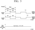
- FIG. 5 is a diagram illustrating an example in which the power consumptions provided by the plurality of driving power are alternating over time.
- the processor 140 may control each of the plurality of inverters 120-1 and 120-2 to generate the driving power having the common driving frequency in the first section 1 and the individual driving frequency in the second section 2.
- the processor 140 may control the plurality of inverters 120-1 and 120-2 to provide the generated driving power to the plurality of corresponding heating coils 110-1 and 110-2.
- an output level of a heating coil is input (S1010). If a plurality of heating coils are provided, an output level of each of the plurality of heating coils may be input.
- the individual driving frequency at which an average of a power consumption of a specific inverter generated in a first section 1, in which the common driving frequency is applied, and a power consumption of a specific inverter generated in a second section 2, in which the individual driving frequency is applied, is the same as the target power of the corresponding heating coil may be calculated.
- the plurality of inverters may be controlled to generate the driving power having the common driving frequency in the first section 1 and the individual driving frequencies in the second section 2.
- the generated driving power may be provided to the heating coil (S1040). If the plurality of heating coils are provided, the generated plurality of driving powers may be provided to the plurality of heating coils, respectively.
- the method for controlling the cooking apparatus of the disclosure has an effect of preventing the instantaneous output of the driving power at a specific time point from exceeding an acceptable range, by controlling the plurality of driving powers to have the plurality of driving frequencies.
- the control method illustrated in FIG. 10 may be executed on an electronic device having the configuration of FIG. 1 or FIG. 2 and may also be executed on a cooking apparatus having other configurations.
- the non-transitory computer-readable medium is not a medium storing data for a short period of time such as a register, a cache, or a memory, but may refer to a medium that semi-permanently stores data and is readable by a machine.
- the various applications or programs described above may be stored and provided to the non-transitory computer-readable medium such as a CD, a DVD, a hard disk drive, a Blu-ray disc, a USB, a memory card, and a ROM.
Landscapes
- Engineering & Computer Science (AREA)
- Physics & Mathematics (AREA)
- Electromagnetism (AREA)
- Power Engineering (AREA)
- Computer Networks & Wireless Communication (AREA)
- Induction Heating Cooking Devices (AREA)
- General Induction Heating (AREA)
- Electric Stoves And Ranges (AREA)
- Control Of High-Frequency Heating Circuits (AREA)
Description
- The disclosure relates to a cooking apparatus and a control method therefor, and more particularly to a cooking apparatus for providing a driving power alternately having a plurality of driving frequencies to a heating coil and a control method therefor.
- The disclosure relates to a cooking apparatus and a control method therefor, and more particularly to a cooking apparatus for providing a driving power alternately having a plurality of driving frequencies to a heating coil and a control method therefor.
US 7910865 discloses an arrangement for controlling induction coils of an induction cooking hob, the induction coils being operated in two modes.
EP 2469972 discloses a cooking appliance with at least two heating frequency units and with at least one control unit which is provided to set a respective average output power of the heating frequency units.
EP 2911472 discloses a cooking appliance with a plurality of inverters and a control unit to operate the inverters together.
EP 2469970 discloses a cooking appliance device with at least two heating frequency units and with at least one control unit which is provided to set a respective average output power of the heating frequency units. - An object of the disclosure is to provide a cooking apparatus for providing a driving power alternately having a plurality of driving frequencies to a heating coil and a control method therefor.
According to an aspect of the disclosure, there is provided a method for controlling a cooking apparatus as set out in claim 1. According to another aspect of the disclosure, there is provided a cooking apparatus as set out in claim 8. - According to an aspect of the disclosure, there is provided a method for controlling a cooking apparatus, the method including receiving an output level regarding a heating coil, determining a plurality of driving frequencies regarding a driving power based on the output level, generating a driving power alternately having the plurality of determined driving frequencies, and providing the generated driving power to the heating coil.
- According to another aspect of the disclosure, there is provided a cooking apparatus including a heating coil configured to generate a magnetic field for heating a cooking container, an inverter configured to provide a driving power to the heating coil, an input device configured to receive an output level regarding the heating coil, and a processor configured to determine a plurality of driving frequencies regarding the driving power based on the output level, generate a driving power alternately having the plurality of determined driving frequencies, and control the inverter to provide the generated driving power to the heating coil.
-
-
FIG. 1 is a block diagram illustrating a simple configuration of a cooking apparatus according to an embodiment; -
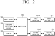
FIG. 2 is a block diagram illustrating a specific configuration of a cooking apparatus according to an embodiment; -
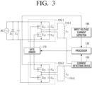
FIG. 3 is a circuit diagram of a cooking apparatus according to an embodiment; -
FIGS. 4 and5 are diagrams illustrating an example of a driving power alternately having a plurality of driving frequencies as according to the invention; -
FIG. 6 is a diagram illustrating an operation of changing a driving frequency of a driving power; -
FIG. 7 is a diagram illustrating an operation of adjusting a change time of a driving frequency of a driving power; -
FIGS. 8 and9 are diagrams illustrating an example of a plurality of driving powers having different phases; and -
FIG. 10 is a flowchart for illustrating a method for controlling a cooking apparatus according to an embodiment. - The disclosure will be described in greater detail below after briefly explaining the terms used in the disclosure.
- The terms "first," "second," or the like may be used for describing various elements but the elements may not be limited by the terms. The terms are used only to distinguish one element from another.
- In the specification, a "cooking apparatus" may refer to an apparatus for heating, reheating, or cooling foods by using a heat supply power such as gas, power, or steam. Examples of such a cooking apparatus may include a gas stove, a microwave, an oven, a toaster, a coffee machine, a grill, or an induction heating cooking apparatus.
- Hereinafter, the disclosure will be described in more detail with reference to the drawings.
-
FIG. 1 is a block diagram illustrating a simple configuration of a cooking apparatus according to an embodiment. - Referring to
FIG. 1 , acooking apparatus 100 may include aheating coil 110, aninverter 120, aninput device 130, and aprocessor 140. - The
heating coil 110 may perform a heating operation based on a driving power provided from theinverter 120. Such a cooking coil may be a heating element or an induction heating coil. For example, if the heating coil is a heating element, the heating coil may directly radiate heat based on the driving power, and if the heating coil is an induction heating coil, the heating coil may heat a cooking container on a burner using an induction current. - Herein, in a case of the cooking apparatus using the induction heating coil, if an alternating current is supplied to the induction heating coil, a magnetic field passing through the inner side of the induction heating coil is induced. The induced magnetic field may pass a bottom surface of the cooking container, an eddy current which is a rotating current is generated on the bottom surface, and the bottom surface of the cooking container may be heated by the generated eddy current.
- In addition, an intensity of the magnetic field generated in the induction heating coil may be changed according to a frequency of the alternating current supplied to the induction heating coil. Specifically, as the frequency of the alternating current supplied to the induction heating coil increases, the intensity of the magnetic field decreases, and as the frequency of the alternating current supplied to the induction heating coil decreases, the intensity of the magnetic field increases.
- Accordingly, the intensity of the magnetic field of the induction heating coil may be adjusted by adjusting a driving frequency of the driving power supplied to the induction heating coil, thereby adjusting power consumption of the induction heating coil. Hereinafter, for convenience of the description, the
heating coil 110 may be assumed as the induction heating coil. - The
inverter 120 may provide the driving power to theheating coil 110. Specifically, theinverter 120 may generate a power input from the outside as a driving power corresponding to an output level so that the driving power corresponding to the output level input from a user is provided to the heating coil, and provide the generated power to each heating coil. - More specifically, since the intensity of the magnetic field which is able to be generated by the heating coil is changed according to the driving frequency of the driving power as described above, the
inverter 120 may provide the driving power corresponding to the output level of the heating coil by adjusting the driving frequency. Meanwhile, the specific configuration and operation of theinverter 120 will be described with reference toFIG. 3 . - The
input device 130 may receive a user command regarding the heating coil from the user. The user command herein may refer to a command for the heating coil to be controlled to perform an operation of turning on/off or to receive selection of an output level so that the heating coil is heated to a degree of the corresponding heating. For the output level, a corresponding value (e.g., 1, 2, 3, and 4) may be directly received or a relative change value (e.g., +1/-1) may be received. - The
input device 130 may be implemented as a plurality of physical buttons or switches and may also be implemented as a touch screen for also performing a display function of displaying an operation state and the like. - The
processor 140 may control each configuration of thecooking apparatus 100. Specifically, if the user command for the heating coil is received via theinput device 130, theprocessor 140 may control the inverter so that the heating coil performs the operation corresponding to the received user command. - For example, if the user command for requesting 2-step output with respect to the
heating coil 110 is received, theprocessor 140 may control theinverter 120 so that theinverter 120 generates the driving power corresponding to the 2-step output and provides the driving power to theheating coil 110. - For this, the
processor 140 may calculate the driving frequency regarding the driving power corresponding to the input output level. For example, if an a level at which a power of 1,500 W is necessary is input, theprocessor 140 may determine 25 KHz as the driving frequency for supplying the power of 1,500 W. - In addition, the
processor 140 may calculate a plurality of driving frequencies regarding the driving power based on the input output level. Specifically, theprocessor 140 may calculate the plurality of driving frequencies different from each other to provide a target power corresponding to the input output level. - For example, if the a level at which the power of 1,500 W is necessary is input and the driving frequency for supplying the power of 1,500 W is 25 KHz when providing the driving power as one driving frequency, the
processor 140 may calculate the plurality of driving frequencies, 23 KHz and 27 KHz having an average value of 25 KHz, as the driving frequencies. - Meanwhile, the number of the plurality of driving frequencies may be 3 or more, other than 2 as described above, and the method for calculating the plurality of driving frequencies is not limited to the example described above.
- The
processor 140 may generate the driving power having the calculated driving frequencies and control theinverter 120 to provide the generated driving power to theheating coil 110. Specifically, if one driving frequency corresponding to the input output level is calculated, theprocessor 140 may control theinverter 120 to generate the driving power having the calculated one driving frequency. - Alternatively, if the plurality of driving frequencies corresponding to the input output level are calculated, the
processor 140 may control theinverter 120 to generate the driving power alternately having the plurality of driving frequencies. - For example, if the
processor 140 calculates 23 kHz and 27 KHz as the plurality of driving frequencies, theprocessor 140 may control theinverter 120 to generate the driving power having a repeated change of the driving frequencies with a frequency of 23 KHz during a predetermined first period and a frequency of 27 KHz during a predetermined second period. - The
processor 140 may control theinverter 120 to provide the generated driving power to theheating coil 110. - In addition, hereinabove, the simple configuration configuring the cooking apparatus has been illustrated and described, and various configurations may be added in the implementation. This will be described below with reference to
FIG. 2 . -
FIG. 2 is a block diagram illustrating a specific configuration of a cooking apparatus according to an embodiment. - Referring to
FIG. 2 , thecooking apparatus 100 may include a plurality of heating coils 110-1 and 110-2, a plurality of inverters 120-1 and 120-2, theinput device 130, theprocessor 140, acurrent detection device 150, and adisplay 160. - The plurality of heating coils 110-1 and 110-2 may include the first heating coil 110-1 and the second heating coil 110-2. Each of the plurality of heating coils 110-1 and 110-2 may be an induction heating coil for generating a magnetic field for heating a cooking container.
- The plurality of inverters 120-1 and 120-2 may include the first inverter 120-1 and the second inverter 120-2. The first inverter 120-1 may provide the driving power to the first heating coil 110-1 and the second inverter 120-2 may provide the driving power to the second heating coil 110-2.
- The
input device 130 may receive a user command for each of the plurality of heating coils 110-1 and 110-2. - The
processor 140 may calculate a common driving frequency regarding the driving power of each of the plurality of heating coils 110-1 and 110-2 based on the output level of each of the plurality of heating coils 110-1 and 110-2. - Specifically, the
processor 140 may determine the common driving frequency based on the target power of the heating coil having a high output level among the plurality of heating coils 110-1 and 110-2 and control the inverter corresponding to the heating coil having a high output level to provide the driving power having the common driving frequency. Theprocessor 140 may control the inverter corresponding to the heating coil with a low output level to intermittently provide the driving power having the common driving frequency. - However, in the above method, if an instantaneous output exceeds an acceptable range at the time point when the plurality of inverters 120-1 and 120-2 provide the driving power at the same time, the target power may not be provided to each of the plurality of heating coils 110-1 and 110-2.
- In order to solve such a problem, the disclosure describes a method for generating the driving power having the plurality of driving frequencies, not generating the driving power having one driving frequency.
- The
processor 140 may calculate the plurality of driving frequencies regarding the driving power of each of the plurality of heating coils 110-1 and 110-2 based on the output level of each of the plurality of heating coils 110-1 and 110-2. Specifically, theprocessor 140 may calculate the plurality of driving frequencies different from each other regarding the driving power of each of the plurality of heating coils 110-1 and 110-2 to provide the target power corresponding to the output level of each of the plurality of heating coils 110-1 and 110-2. - For example, if the target power corresponding to the output level of the first heating coil 110-1 is 1,500 W and the driving frequency for supplying the power of 1,500 W is 25 KHz, the
processor 140 may determine 23 KHz and 27 KHz having an average of 25 KHz as the plurality of driving frequencies of the first heating coil 110-1. In addition, if the target power corresponding to the output level of the second heating coil 110-2 is 1,200 W and the driving frequency for supplying the power of 1,200 W is 22 KHz, theprocessor 140 may determine 23 KHz and 21 KHz having an average value of 22 K-Hz as the plurality of driving frequencies of the second heating coil 110-2. - Meanwhile, the number of plurality of driving frequencies may be 3 or more, other than 2 as described above, and the method for calculating the plurality of driving frequencies is not limited to the example described above.
- The operation according to the invention of calculating the plurality of driving frequencies based on the output level of each of the plurality of heating coils 110-1 and 110-2 will be described later with reference to
FIGS. 4 and5 . - The
processor 140 may control the plurality of inverters 120-1 and 120-2 to generate the plurality of driving powers alternately having the plurality of driving frequencies of each of the plurality of heating coils 110-1 and 110-2. - For example, if the plurality of driving frequencies of the first heating coil 110-1 are 23 KHz and 27 KHz and the plurality of driving frequencies of the second heating coil 110-2 are 23 KHz and 21 KHz, the
processor 140 may control the first inverter and the second inverter so that the first inverter 120-1 generates a first driving power alternately having frequencies of 23 KHz and 27 KHz and the second inverter generates a second driving power alternately having frequencies of 23 KHz and 21 KHz. - When generating each of the plurality of driving powers, the
processor 140 may control the plurality of inverters 120-1 and 120-2 so that the time points when the frequency is changed coincide with each other. For example, theprocessor 140 may control the first inverter 120-1 and the second inverter 120-2 to generate a driving power having a first driving frequency during the predetermined first period and generate a driving power having a second driving frequency during the predetermined second period. - The
processor 140 may control the plurality of inverters 120-1 and 120-2 to provide the generated plurality of driving powers to each of the plurality of heating coils 110-1 and 110-2. - As descried above, the
processor 140 may control each of the plurality of inverters 120-1 and 120-2 to provide the driving power having the plurality of driving frequencies to provide the target power corresponding to the output level of each of the plurality of heating coils 110-1 and 110-2. - The above method is different from the method in which an inverter intermittently provides a power by repeating on and off operations of the inverter which is the method of the related art. Specifically, in the disclosure, each driving power provided to each of the plurality of heating coils 110-1 and 110-2 may change the frequency according to the time point, but continuously provide the power to distribute the power without the on and off operations, thereby preventing a phenomenon of increase in instantaneous output at a specific time point.
- The
current detection device 150 may be connected to each of the plurality of heating coils 110-1 and 110-2 to detect a current flowing to the plurality of heating coils 110-1 and 110-2. Thecurrent detection device 150 may provide information of the detected current to theprocessor 140. - The
processor 140 may calculate power consumption of each of the plurality of heating coils 110-1 and 110-2 based on the information of the current received from thecurrent detection device 150. Theprocessor 140 may compare the power consumption and a target power of each of the plurality of heating coils 110-1 and 110-2. If there is a difference, theprocessor 140 may control theinverter 120 to change the frequency of the driving power or change the phase so that the power consumption coincides with the target power. - Meanwhile, the specific operation of the
processor 140 to control theinverter 120 so that the power consumption coincides with the target power will be described later with reference toFIGS. 6 to 8 . - The
display 160 may display various information provided from thecooking apparatus 100. Specifically, thedisplay 160 may display an operation state of thecooking apparatus 100 or display a user interface window for a function selected by a user or option selection. - Meanwhile, in illustrating and describing
FIG. 2 , it is illustrated and described that two heating coils and two inverters are included, but in the implementation, three or more heating coils and three or more inverters may be included. - In the related art, since the plurality of driving powers provided to the plurality of heating coils are generated based on one driving frequency, the instantaneous output of the driving power at a specific time point exceeded an acceptable range, which makes it difficult to achieve the target output.
- However, as described above, in the disclosure, by controlling the plurality of driving powers to have a plurality of driving frequencies, it is possible to exhibit an effect of preventing the instantaneous output of the driving power at a specific time point from exceeding an acceptable range.
-
FIG. 3 is a flowchart of a cooking apparatus according to an embodiment. - Referring to
FIG. 3 , thecooking apparatus 100 may include a power supply AC, a rectifier circuit D1, a smoothing circuit C1, the plurality of inverters 120-1 and 120-2, the plurality of heating coils 110-1 and 110-2, theprocessor 140, thecurrent detection device 150, agate driver 170, and an input voltagecurrent detector 180. - The power supply AC may be connected to an external commercial power supply to receive power. The power supply AC may include a power switch, and if a power-on signal is received via the
input device 130, the power supply AC may turn on the power switch to be connected to the external commercial power supply. - The rectifier D1 may receive power from the power supply AC to perform rectification and may transfer the rectified power to the smoothing circuit C1. The rectifier circuit D1 may include at least one diode and may also include a bridge diode.
- The smoothing circuit C1 may remove ripple of the power rectified by the rectifier circuit D1 and transfer the power to the plurality of inverters 120-1 and 120-2. Specifically, the smoothing circuit C1 may convert the applied power into a direct current by removing a pulsating current and may transfer the power of the converted current to the plurality of inverters 120-1 and 120-2.
- The plurality of inverters 120-1 and 120-2 may be connected to the plurality of heating coils 110-1 and 110-2, respectively, and may generate the driving power to provide it to each of the plurality of heating coils 110-1 and 110-2.
- The first inverter 120-1 may include a plurality of switching elements Q11 and Q12 which are connected between both ends of the smoothing circuit C1 and receive an operation signal from the
gate driver 170, may include a plurality of capacitors C2 and C3 connected to both ends of the smoothing circuit C1, and may be connected to the first heating coil 110-1. - The second inverter 120-2 may include a plurality of switching elements Q21 and Q22 which are connected between both ends of the smoothing circuit C1 and receive an operation signal from the
gate driver 170, may include a plurality of capacitors C4 and C5 connected to both ends of the smoothing circuit C1, and may be connected to the second heating coil 110-2. - The plurality of inverters 120-1 and 120-2 may repeat turn-on and turn-off operations of the plurality of switching elements Q11, Q12, Q21, and Q22 according to the operation signal input from the
gate driver 170, generate a current with a direction changing accordingly and supply the current to each of the plurality of heating coils 110-1 and 110-2. - For example, if the first switching element Q11 of the first inverter 120-1 is turned on and the second switching element Q12 is turned off, a driving current in a first direction may be supplied to the first heating coil 110-1, and if the first switching element Q11 is turned off and the second switching element Q12 is turned on, a driving current in a second direction may be supplied to the first heating coil 110-1.
- A cycle of the turn-on and turn-off operations of the plurality of switching elements Q11, Q12, Q21, and Q22 of the plurality of inverters 120-1 and 120-2 may be determined according to the driving frequency of the driving power. The power consumption of the heating coil changes according to the cycle of the turn-on and turn-off operations of the plurality of switching elements Q11, Q12, Q21, and Q22, and accordingly, the
processor 140 may change the power consumption of each heating coil by adjusting the driving frequency of the driving power. - The
processor 140 may change the cycle of the turn-on and turn-off operations of the plurality of switching elements Q11, Q12, Q21, and Q22 according to the plurality of driving frequencies. - Specifically, the
processor 140 may provide a control instruction for instructing to generate the driving power having a first driving frequency during a predetermined first period and a second driving frequency during a predetermined second period to thegate driver 170. The operation signal may be provided to the plurality of switching elements Q11, Q12, Q21, and Q22 so that thegate driver 170 performs the operation corresponding thereto. - In addition, the
processor 140 may perform pulse width modulation (PWM) regarding the turn-on and turn-off operations of the plurality of switching elements Q11, Q12, Q21, and Q22. - The plurality of heating coils 110-1 and 110-2 may generate a magnetic field by using the driving power provided from the plurality of inverters 120-1 and 120-2. The generated magnetic field may pass through a bottom surface of a cooking container, an eddy current which is a rotating current may be generated on the bottom surface, and the bottom surface of the cooking container may be heated by the generated eddy current.
- The
current detection device 150 may be connected to each of the plurality of heating coils 110-1 and 110-2, detect a current flowing to each of the plurality of heating coils 110-1 and 110-2, and provide information of the detected current to theprocessor 140. - For example, the
current detection device 150 may include a current transformer for reducing a magnitude of a current in proportion to a magnitude of a current supplied to the first heating coil 110-1 and an ampere meter for detecting the magnitude of the reduced current. - In another example, the
current detection device 150 may include a shunt resistance connected to the first heating coil 110-1 and a measurement device (not illustrated) for measuring a voltage drop occurring in the shunt resistance. - The
gate driver 170 ma generate an operation signal regarding the turn-on and turn-off operations of the plurality of switching elements Q11, Q12, Q21, and Q22 according to the control instruction of theprocessor 140. Thegate driver 170 may be implemented to be included in theprocessor 140 and may be implemented as a separate device from theprocessor 140. - The input voltage
current detector 180 may be connected to the power supply AC to detect a current or a voltage of the input power provided to the plurality of inverters 120-1 and 120-2. The input voltagecurrent detector 180 may provide a detection result to theprocessor 140. - The
processor 140 may calculate a phase of a current flowing to each heating coil based on the detection result of the input voltagecurrent detector 180 and thecurrent detection device 150. The processor may change the phase of the driving power provided to each of the heating coils 110-1 and 110-2 based on the calculated phase information. This will be described later in detail with reference toFIGS. 8 and9 . -
FIGS. 4 and5 are diagrams illustrating the invention, whereby a driving power alternately has a plurality of driving frequencies. -
FIG. 4 is a diagram illustrating the invention in which the driving frequencies of the plurality of driving powers are alternating over time.FIG. 5 is a diagram illustrating an example in which the power consumptions provided by the plurality of driving power are alternating over time. - Referring to
FIG. 4 , it may be confirmed that the driving frequency of the driving power provided to the first inverter 120-1 has a first frequency f1 during a first section 1 and has a second frequency f2 during a second section 2. In addition, it may be confirmed that the driving frequency of the driving power provided to the second inverter 120-2 has the first frequency f1 during the first section 1 and has a third frequency f3 during the second section 2. - In other words, the driving power of each inverter may have the first frequency f1 which is the common driving frequency during the first section 1 and may have the second frequency f2 and the third frequency f3 which are individual driving frequencies during the second section 2.
- Hereinafter, a method for determining the common driving frequency f1 and the driving frequencies f2 and f3 for each heating coil will be described.
- First, the
processor 140 may calculate a target power of each of the plurality of heating coils 110-1 and 110-2 based on an output level input to the plurality of heating coils 110-1 and 110-2. - The
processor 140 may determine the common driving frequency f1 of the driving power generated by the plurality of inverters 120-1 and 120-2 based on a total of the target powers of the plurality of heating coils 110-1 and 110-2. - Specifically, based on an average of the total of the target powers of the plurality of heating coils 110-1 and 110-2, the
processor 140 may determine the common driving frequency f1 corresponding thereto. Thecooking apparatus 100 may pre-store information of the common driving frequency f1 corresponding to the target power in a memory (not illustrated) in order to determine the common driving frequency f1 corresponding to the average of the total of the target powers. - For example, if the target power of the first heating coil 110-1 is 1,800 W and the target power of the second heating coil 110-2 is 1,200 W, the common driving frequency f1 of the driving power may be determined based on 1,500 W which is an average of 3,000 W which is the total of the target powers. Meanwhile, the method for determining the common driving frequency is not limited to the above example.
- The
processor 140 may calculate the individual driving frequencies of the plurality of heating coils 110-1 and 110-2 corresponding to the output level and the common driving frequency of each of the plurality of heating coils 110-1 and 110-2. - Specifically, the
processor 140 may calculate the individual driving frequency at which an average of a power consumption of a specific inverter generated in the first section 1, in which the common driving frequency is applied, and a power consumption of a specific inverter generated in the second section 2, in which the individual driving frequency is applied, is the same as the target power of the corresponding heating coil. - For example, referring to
FIG. 5 , the power consumption of the first heating coil in the first section 1 may be assumed as TP11, the power consumption of the second heating coil in the first section 1 may be assumed as TP21, the power consumption of the first heating coil in the second section 2 may be assumed as TP12, and the power consumption of the second heating coil in the second section 2 may be assumed as TP22. - The
processor 140 may calculate the individual driving frequencies f2 and f3 so that the average of TP11 and TP12 is the same as the target power of the first heating coil 110-1 and the average of TP21 and TP22 is the same as the target power of the second heating coil 110-2. - In addition, the
processor 140 may calculate the individual driving frequencies so that the total of the power consumptions of the plurality of inverters 120-1 and 120-2 generated in the first section 1, in which the common frequency is applied, is the same as the total of the power consumptions of the plurality of inverters 120-1 and 120-2 generated in the second section 2, in which the individual driving frequencies are applied. - For example, referring to
FIG. 5 , theprocessor 140 may calculate the individual driving frequencies f2 and f3 to satisfy TP11 + TP21 = TP12 + TP22. - As described above, when the common driving frequency f1 and the driving frequencies f2 and f3 for each heating coil are determined, as illustrated in
FIG. 5 , the total of the power consumptions (TP = TP1 + TP2) provided by each of the plurality of inverters 120-1 and 120-2 may have a constant value over time. At the same time, the power consumption same as the target power of each of the plurality of heating coils 110-1 and 110-2 may be provided. Accordingly, it is possible to provide suitable power to each coil while preventing the instantaneous output of thecooking apparatus 100 at a specific time point from exceeding an acceptable range. - In addition, the
processor 140 may calculate the individual driving frequencies so that a difference between the individual driving frequencies f2 and f3 has a predetermined value or more. Specifically, theprocessor 140 may calculate the individual driving frequencies so that the individual driving frequency f3 of the heating coil having a lower target power is higher than the individual driving frequency f2 of the heating coil having a higher target power by the predetermined value or more. - The predetermined value herein may correspond to an audible frequency range. When the plurality of inverters generate the driving powers operating at the individual driving frequencies, an interference sound may be generated due to a difference between the driving frequencies of each driving power. If the difference between the individual driving frequencies f2 and f3 corresponds to the audible frequency range, the human may hear the interference sound.
- Accordingly, the predetermined value may correspond to 17 Khz in the audible frequency range, and therefore, the noise may be prevented without using the same driving frequency.
- Meanwhile, the individual driving frequency f3 of the heating coil having a lower target power may be determined as 0, if the target power is satisfied only with the power consumption generated in the first section 1 operating at the common driving frequency f1.
- The
processor 140 may control each of the plurality of inverters 120-1 and 120-2 to generate the driving power having the common driving frequency in the first section 1 and the individual driving frequency in the second section 2. Theprocessor 140 may control the plurality of inverters 120-1 and 120-2 to provide the generated driving power to the plurality of corresponding heating coils 110-1 and 110-2. - Meanwhile, in illustrating and describing
FIG. 5 , it is illustrated and described that two heating coils and two inverters are included, but in the implementation, three or more heating coils and three or more inverters may be included. -
FIG. 6 is a diagram illustrating an operation of changing a driving frequency of a driving power. - The
processor 140, as described above, may calculate the common driving frequency and the individual driving frequencies based on the output level of each of the plurality of heating coils 110-1 and 110-2 and control the plurality of inverters 120-1 and 120-2 to generate the driving power alternately having the calculated plurality of driving frequencies. - However, since the plurality of heating coils 110-1 and 110-2 are adjacent to each other, the power actually provided to each of the plurality of heating coils 110-1 and 110-2 may not satisfy the target power due to interference of magnetic fields or other reasons. Accordingly, the
processor 140 may calculate the power consumption of each of the plurality of heating coils 110-1 and 110-2 using current information detected through thecurrent detection device 150 and give a feedback to have a value same as the target power. - Hereinafter, the operation in which the
processor 140 gives a feedback by changing the individual driving frequency of each of the plurality of driving powers will be described. In addition, the operation of giving a feedback by changing the individual driving frequency may be performed regardless of the size of the target output of each of the plurality of heating coils 110-1 and 110-2 and may be applied to all of the plurality of inverters 120-1 and 120-2 by the same method, and therefore the description will be made using the first heating coil 110-1 as an example. - First, the
processor 140 may confirm whether the power consumption of the first heating coil 110-1 detected through thecurrent detection device 150 is lower than the target power of the first heating coil 110-1 (S610). - If the power consumption is lower than the target power (S610-Y), the
processor 140 may control the first inverter 120-1 to provide increased power consumption by reducing the individual driving frequency f2. On the other hand, if the power consumption is not lower than the target power (S610-N), theprocessor 140 may confirm whether the power consumption is higher than the target power (S630). - If the power consumption is higher than the target power (S630-Y), the
processor 140 may control the first inverter 120-1 to provide reduced power consumption by increasing the individual driving frequency f2 (S640). On the other hand, if the power consumption is not higher than the target power (S630-N), in other words, if the power consumption is the same as the target power, the frequency change may not be performed. - Meanwhile, if a difference between the individual driving frequency of the driving power provided to the first heating coil 110-1 and the individual driving frequency of the driving power provided to the second heating coil 110-2 does not have the predetermined value or more due to the feedback operation of the
processor 140, a noise due to the interference sound may be generated. In this case, theprocessor 140 may change each individual driving frequency to the same frequency. -
FIG. 7 is a diagram illustrating an operation of adjusting a change time of a driving frequency of a driving power. - The
processor 140 may perform a feedback operation by adjusting a change time of the driving frequency of the driving power, in addition to the feedback operation through the change of the individual driving frequency described above. - Meanwhile, the operation for giving a feedback by adjusting the change time of the driving frequency of the driving power may be performed regardless of the size of the target output of each of the plurality of heating coils 110-1 and 110-2 and may be applied to all of the plurality of inverters 120-1 and 120-2 by the same method, and therefore the description will be made using the first heating coil 110-1 as an example.
- First, the
processor 140 may confirm whether the power consumption of the first heating coil 110-1 detected through thecurrent detection device 150 is higher than the target power of the first heating coil 110-1 (S710). - If the power consumption of the first heating coil 110-1 is higher than the target power of the first heating coil 110-1 (S710-Y), the
processor 140 may confirm whether the power consumption in the first section 1 is higher than the power consumption in the second section 2 (S720). - If the power consumption in the first section 1 is higher than the power consumption in the second section 2 (S720-Y), the
processor 140 may reduce the first section 1 and increase the second section 2, in order to reduce the power consumption of the first heating coil 110-1. - On the other hand, if the power consumption in the first section 1 is lower than the power consumption in the second section 2 (S720-N), the
processor 140 may increase the first section 1 and reduce the second section 2, in order to reduce the power consumption of the first heating coil 110-1. - Meanwhile, if the power consumption of the first heating coil 110-1 is not higher than the target power of the first heating coil 110-1 (S710-N), the
processor 140 may confirm whether the power consumption of the first heating coil 110-1 is lower than the target power of the first heating coil 110-1 (S750). - If the power consumption of the first heating coil 110-1 is lower than the target power of the first heating coil 110-1 (S750-Y), the
processor 140 may confirm whether the power consumption in the first section 1 has a higher value than the consumption power in the second section 2 (S760). - If the power consumption in the first section 1 is higher than the power consumption in the second section 2 (S760-Y), the
processor 140 may increase the first section 1 and reduce the second section 2, in order to increase the power consumption of the first heating coil 110-1 (S740). - On the other hand, if the power consumption in the first section 1 is lower than the power consumption in the second section 2 (S760-N), the
processor 140 may reduce the first section 1 and increase the second section 2, in order to increase the power consumption of the first heating coil 110-1. - Meanwhile, if the power consumption of the first heating coil 110-1 is not lower than the target power of the first heating coil 110-1 (S750-N), in other words, if the power consumption of the first heating coil 110-1 is the same as the target power, the change of the first section 1 and the second section 2 may not be performed.
- Meanwhile, in illustrating and describing
FIG. 7 , it is illustrated and described that the sections corresponding to each of the plurality of driving frequencies are two in total which are the first section and the second section, but in the implementation, a driving power having three or more driving frequencies may be generated, three or more sections may be provided accordingly, and a feedback may be given by adjusting the three or more sections described above. -
FIGS. 8 and9 are diagrams illustrating an example of a plurality of driving powers having different phases. -
FIG. 8 is a diagram illustrating an example of the turn-on and turn-off operations of the switching element of the plurality of inverters andFIG. 9 is a diagram illustrating an example of a change of a power according to a phase difference of the driving power of each of the plurality of inverters. - Referring to
FIG. 8 , regarding the first inverter, the turn-on and turn-off operations of the first switching element Q11 may be confirmed on a high side of the first inverter 120-1 and the turn-on and turn-off operations of the second switching element Q12 may be confirmed on a low side of the first inverter 120-1. - In addition, regarding the second inverter, the turn-on and turn-off operations of the first switching element Q21 may be confirmed on a high side of the second inverter 120-2 and the turn-on and turn-off operations of the second switching element Q22 may be confirmed on a low side of the second inverter 120-2.
- In relating to the operation of the switching element, as described above, the switching element of each inverter may repeat the turn-on and turn-off operations and the switching elements in one inverter may be operated not to overlap the turn-on or turn-off operation.
- Meanwhile, the time point when the high side of each inverter is turned on may be the same or different and a difference thereof may be expressed as a phase based on the time point when the high side is turned on.
- In other words, referring to
FIG. 8 , it may be confirmed that there is a difference between the time point when the high side of the first inverter is turned on and the time point when the high side of the second inverter is turned on, and this may be expressed as a phase difference between the inverters. - Specifically, if the entire period including the first section 1 and the second section 2 of each inverter is assumed as 360 degrees and the time point of the turn-on of the high side of the first inverter is assumed as 0 degree, the time from the time point of the turn-on of the high side of the first inverter until the time point of the turn-on of the high side of the second inverter may be expressed as an angle.
- For example, if the entire period is 10 seconds, and the time from the time point of the turn-on of the high side of the first inverter until the time point of the turn-on of the high side of the second inverter is 1 second, the phase of the second inverter may be expressed as 1/10 * 360 = 36.
- Meanwhile, as described above, if the phases of the driving power of each of the plurality of inverters 120-1 and 120-2 are different, the power of each driving power may be changed. This is because, if the plurality of heating coils are positioned to be adjacent to each other and the driving power having the same frequency is input, the line of induction generated from one heating coil may affect a heating area of another coil as induced voltage.
- Specifically, referring to
FIG. 9 , if the phase of the driving power generated by the first inverter 120-1 is ahead of the phase of the driving power generated by the second inverter 120-2, the power of the driving power generated by the first inverter 120-1 may increase. In contrast, the power of the driving power generated by the second inverter 120-2 may be reduced. - Meanwhile, the gradual increase in power when the phase of the driving power generated by the first inverter 120-1 is ahead is limited to a case where the phase is ahead from 0 degrees to 90 degrees. If it exceeds 90 degrees, the power of the driving power generated by the first inverter 120-1 may be reduced again. In addition, the feature described above may be applied to only the driving powers having the same frequencies.
- Accordingly, the
processor 140 may perform the feedback operation by changing the phase of each of the plurality of driving powers, in addition to the feedback operation through the change of the individual driving frequency and the adjustment of the change time of the driving frequency of the driving power using the above feature. - First, the
processor 140 may confirm whether the power consumption of the first heating coil 110-1 is lower than the target power of the first heating coil 110-1. - If the power consumption is lower than the target power, the
processor 140 may set so that the phase when the driving power of the first heating coil 110-1 is operated at the common frequency is ahead of the phase of the driving power provided to the second heating coil 110-2. On the other hand, if the power consumption is higher than the target power, theprocessor 140 may set so that the phase when the driving power of the first heating coil 110-1 is operated at the common frequency is behind the phase of the driving power provided to the second heating coil 110-2. - Meanwhile, in illustrating and describing
FIGS. 8 and9 , the feedback method through the phase difference between two driving powers is illustrated and described, but in the implementation, a feedback method through the phase difference between three or more driving powers may be performed. -
FIG. 10 is a flowchart for illustrating a method for controlling a cooking apparatus according to an embodiment. - Referring to
FIG. 10 , first, an output level of a heating coil is input (S1010). If a plurality of heating coils are provided, an output level of each of the plurality of heating coils may be input. - A plurality of driving frequencies of the driving power may be calculated based on the output level (S1020). Specifically, the plurality of driving frequencies different from each other may be calculated so as to provide a target power corresponding to the input output level.
- If the plurality of heating coils are provided, the plurality of driving frequencies different from each other may be calculated so as to provide a target power corresponding to the input output level of each of the plurality of heating coils.
- Specifically, a common driving frequency which is common for the plurality of heating coils may be calculated. For example, based on an average of a total of the target powers of the plurality of heating coils, the common driving frequency may be determined corresponding thereto.
- An individual driving frequency corresponding to the output level of each of the plurality of heating coils and the determined common driving frequency may be calculated.
- Specifically, the individual driving frequency at which an average of a power consumption of a specific inverter generated in a first section 1, in which the common driving frequency is applied, and a power consumption of a specific inverter generated in a second section 2, in which the individual driving frequency is applied, is the same as the target power of the corresponding heating coil may be calculated.
- In addition, the individual driving frequencies may be calculated so that the total of the power consumptions of the plurality of inverters generated in the first section 1, in which the common frequency is applied, is the same as the sum of the power consumptions of the plurality of inverters generated in the second section 2, in which the individual driving frequency is applied.
- Further, the individual driving frequencies may be calculated so that a difference between the individual driving frequencies has a predetermined value or more. The predetermined value herein may correspond to an audible frequency range.
- A driving power alternately having the calculated plurality of driving frequencies may be generated (S1030). If the plurality of heating coils are provided, the plurality of driving powers alternately having the calculated plurality of driving frequencies of each of the plurality of heating coils may be generated.
- Specifically, the plurality of inverters may be controlled to generate the driving power having the common driving frequency in the first section 1 and the individual driving frequencies in the second section 2.
- The generated driving power may be provided to the heating coil (S1040). If the plurality of heating coils are provided, the generated plurality of driving powers may be provided to the plurality of heating coils, respectively.
- Therefore, the method for controlling the cooking apparatus of the disclosure has an effect of preventing the instantaneous output of the driving power at a specific time point from exceeding an acceptable range, by controlling the plurality of driving powers to have the plurality of driving frequencies. The control method illustrated in
FIG. 10 may be executed on an electronic device having the configuration ofFIG. 1 orFIG. 2 and may also be executed on a cooking apparatus having other configurations. - In addition, the control method described above may be implemented as at least one execution program for executing the above control method and such an execution program may be stored in a non-transitory computer-readable medium.
- The non-transitory computer-readable medium is not a medium storing data for a short period of time such as a register, a cache, or a memory, but may refer to a medium that semi-permanently stores data and is readable by a machine. Specifically, the various applications or programs described above may be stored and provided to the non-transitory computer-readable medium such as a CD, a DVD, a hard disk drive, a Blu-ray disc, a USB, a memory card, and a ROM.
- While preferred embodiments of the disclosure have been shown and described, the disclosure is not limited to the aforementioned specific embodiments, and it is apparent that various modifications can be made by those having ordinary skill in the technical field to which the disclosure belongs, without departing from the disclosure as claimed by the appended claims. Also, it is intended that such modifications are not to be interpreted independently from the technical idea or prospect of the disclosure.
[Industrial Applicability]
[Sequence List Free Text]
Claims (9)
- A method for controlling a cooking apparatus (100), the method comprising:receiving an output level regarding each of a plurality of heating coils (110, 110-1, 110-2);determining a plurality of driving frequencies regarding a driving power of each of the plurality of heating coils (110, 110-1, 110-2) based on the output level of each of the plurality of heating coils (110, 110-1, 110-2);generating a plurality of driving powers alternately having the plurality of determined driving frequencies of each of the plurality of heating coils (110, 110-1, 110-2); andproviding each of the plurality generated driving powers to each of the plurality of heating coils (110, 110-1, 110-2),characterised in thatthe determining the plurality of driving frequencies comprises determining a common driving frequency that is common for the plurality of heating coils (110, 110-1, 110-2), and determining an individual driving frequency corresponding to the determined common driving frequency and so that the driving power provides a target power corresponding to the output level of each of the plurality of heating coils (110, 110-1, 110-2),wherein the determined individual driving frequency of each of the plurality of heating coils (110, 110-1, 110-2) is different to the common driving frequency, andthe generating the driving power of each of the plurality of heating coils (110, 110-1, 110-2) comprises generating a driving power alternately having the two determined driving frequencies which are the common driving frequency and the individual driving frequency of the heating coil (110, 110-1, 110-2).
- The method according to claim 1, wherein the determining comprises determining the common driving frequency and the individual driving frequency so that power consumptions of the cooking apparatus at a time point when the common driving frequency is applied and power consumptions of the cooking apparatus at a time point when the individual driving frequency is applied are same as each other.
- The method according to claim 1, wherein the cooking apparatus comprises a first heating coil (110-1) and a second heating coil (110-2),wherein the determining comprises determining a first driving frequency commonly applied to the first heating coil and the second heating coil, determining a second driving frequency based on an output level corresponding to the first heating coil and the determined first driving frequency, and determining a third driving frequency based on an output level corresponding to the second heating coil and the determined first driving frequency, andwherein the generating the driving power comprises generating a first driving power having the first driving frequency and the second driving frequency and generating a second driving power having the first driving frequency and the third driving frequency.
- The method according to claim 3, wherein the determining comprises determining the first driving frequency based on an average of target power of each of the first heating coil and the second heating coil.
- The method according to claim 4, wherein the determining comprises determining the second driving frequency based on the target power regarding the first heating coil and the determined first driving frequency, and determining the third driving frequency based on the target power regarding the second heating coil and the determined first driving frequency.
- The method according to claim 3, wherein the determining comprises determining the first to third driving frequencies so that a difference between the second driving frequency and the third driving frequency has a predetermined value or more.
- The method according to claim 3, wherein the generating the driving power comprises generating the first driving power and the second driving power so as to have a first driving frequency in a first time section, and generating the first driving power having the second driving frequency and the second driving power having the third driving frequency in the second time section.
- A cooking apparatus (100) comprising:a plurality of heating coils (110, 110-1, 110-2) configured to generate a magnetic field for heating a cooking container;a plurality of inverters (120, 120-1, 120-2) configured to individually provide a driving power to each of the plurality of heating coils (110, 110-1, 110-2);an input device (130) configured to receive an output level regarding each of the plurality of heating coils (110, 110-1, 110-2); anda processor (140) configured to determine a plurality of driving frequencies regarding the driving power of each of the plurality of heating coils (110, 110-1, 110-2) based on the output level of each of the plurality of heating coils (110, 110-1, 110-2), generate a plurality of driving powers alternately having the plurality of determined driving frequencies of each of the plurality of corresponding heating coils (110, 110-1, 110-2), and control the plurality of inverters (120, 120-1, 120-2) to provide each of the plurality of generated driving powers to each of the plurality of corresponding heating coils (110, 110-1, 110-2),characterised in that the processor (140) is further configured to:determine a common driving frequency that is common for the plurality of heating coils (110, 110-1, 110-2); anddetermine an individual driving frequency corresponding to the determined common driving frequency and so that the driving power provides a target power corresponding to the output level of each of the plurality of heating coils (110, 110-1, 110-2),wherein the determined individual driving frequency of each of the plurality of heating coils (110, 110-1, 110-2) is different to the common driving frequency, andthe processor (140) is further configured to control the inverter (120, 120-1, 1202) to generate the driving power of each of the plurality of heating coils (110, 110-1, 110-2) alternately having the two determined driving frequencies which are the common driving frequency and the individual driving frequency of the heating coil (110, 110-1, 110-2).
- The cooking apparatus according to claim 8, wherein the processor is configured to determine the common driving frequency and the individual driving frequency so that power consumptions of the cooking apparatus at a time point when the common driving frequency is applied and a time point when the individual driving frequency is applied are same as each other.
Applications Claiming Priority (2)
| Application Number | Priority Date | Filing Date | Title |
|---|---|---|---|
| KR1020180124190A KR102620662B1 (en) | 2018-10-18 | 2018-10-18 | Cooking apparatus and method for controlling thereof |
| PCT/KR2019/013177 WO2020080725A1 (en) | 2018-10-18 | 2019-10-08 | Cooking apparatus and control method therefor |
Publications (3)
| Publication Number | Publication Date |
|---|---|
| EP3852492A1 EP3852492A1 (en) | 2021-07-21 |
| EP3852492A4 EP3852492A4 (en) | 2021-11-03 |
| EP3852492B1 true EP3852492B1 (en) | 2024-07-03 |
Family
ID=70283271
Family Applications (1)
| Application Number | Title | Priority Date | Filing Date |
|---|---|---|---|
| EP19873159.8A Active EP3852492B1 (en) | 2018-10-18 | 2019-10-08 | Cooking apparatus and control method therefor |
Country Status (5)
| Country | Link |
|---|---|
| US (1) | US12096539B2 (en) |
| EP (1) | EP3852492B1 (en) |
| KR (1) | KR102620662B1 (en) |
| CN (1) | CN112868271B (en) |
| WO (1) | WO2020080725A1 (en) |
Families Citing this family (9)
| Publication number | Priority date | Publication date | Assignee | Title |
|---|---|---|---|---|
| KR102903153B1 (en) | 2020-05-06 | 2025-12-23 | 엘지전자 주식회사 | Induction heating apparatus and method for controlling induction heating apparatus |
| KR102901499B1 (en) * | 2020-05-06 | 2025-12-17 | 엘지전자 주식회사 | Induction heating apparatus and method for controlling induction heating apparatus |
| EP4037432B1 (en) | 2021-01-27 | 2026-01-07 | LG Electronics Inc. | Induction heating apparatus and method for controlling induction heating apparatus |
| CN115528822A (en) * | 2021-06-25 | 2022-12-27 | 恩智浦美国有限公司 | Wireless charger, system and method |
| WO2023106651A1 (en) * | 2021-12-08 | 2023-06-15 | 삼성전자 주식회사 | Induction-heating apparatus |
| JP7822165B2 (en) * | 2021-12-08 | 2026-03-02 | 三星電子株式会社 | induction heating device |
| WO2023113276A1 (en) * | 2021-12-15 | 2023-06-22 | 삼성전자 주식회사 | Cooking device and control method therefor |
| EP4475388A4 (en) * | 2022-02-04 | 2025-12-24 | Wipowerone Inc | Multi-phase power supply device for wireless power transmission and method for controlling it |
| WO2024210622A2 (en) * | 2023-04-05 | 2024-10-10 | 삼성전자주식회사 | Electronic device for controlling target power according to input power of power supply circuit and control method thereof |
Family Cites Families (17)
| Publication number | Priority date | Publication date | Assignee | Title |
|---|---|---|---|---|
| JPS5943279B2 (en) * | 1982-03-08 | 1984-10-20 | 株式会社渡辺鉄工所 | Operation mechanism of the pulling device and lower feeding device in the meat box of a meat cutting machine |
| KR100261518B1 (en) * | 1997-12-30 | 2000-07-15 | 구자홍 | A apparatus for driving of Induction heating cooker and method thereof |
| JP4613585B2 (en) | 2004-11-05 | 2011-01-19 | パナソニック株式会社 | Induction heating device |
| DE102005021888A1 (en) * | 2005-05-04 | 2007-02-15 | E.G.O. Elektro-Gerätebau GmbH | Method and arrangement for power supply of a plurality of induction coils in an induction device |
| ES2338057T5 (en) * | 2007-01-23 | 2023-03-09 | Whirlpool Co | Control method for an induction cooker and induction cooker adapted to carry out said method |
| JP2009087743A (en) * | 2007-09-28 | 2009-04-23 | Toshiba Corp | Heating cooking system, heating cooker and cookware used in the same |
| EP3771288B1 (en) | 2009-10-05 | 2021-12-15 | Whirlpool Corporation | Method for supplying power to induction cooking zones of an induction cooking hob having a plurality of power converters, and induction cooking hob using such method |
| ES2392223B1 (en) * | 2010-12-27 | 2013-10-09 | BSH Electrodomésticos España S.A. | Cooking device device and procedure for said device. |
| EP2469972B1 (en) * | 2010-12-27 | 2017-05-03 | BSH Hausgeräte GmbH | Cooking device and method of controlling the cooking device which diminish in an iterative manner a flicker characteristic. |
| CN103404229B (en) | 2011-02-21 | 2015-07-29 | 三菱电机株式会社 | induction heating cooker |
| JP5979386B2 (en) * | 2011-10-28 | 2016-08-24 | パナソニックIpマネジメント株式会社 | Induction heating cooker |
| CN104322142B (en) * | 2012-05-18 | 2016-05-04 | 高周波热錬株式会社 | Induction heating system, induction heating method, output monitoring device, output monitoring method and induction heating device |
| JP5943279B2 (en) | 2012-05-18 | 2016-07-05 | 高周波熱錬株式会社 | Output monitoring apparatus and method, and induction heating system |
| JP5319848B2 (en) | 2013-02-14 | 2013-10-16 | 三井造船株式会社 | Induction heating apparatus and power control method for induction heating apparatus |
| EP2911472B2 (en) * | 2013-12-20 | 2022-11-09 | BSH Hausgeräte GmbH | Cooking appliance, in particular cooking hob device, with a plurality of inverters |
| KR101735754B1 (en) | 2015-09-08 | 2017-05-15 | 자원전자 주식회사 | A induction coil driving circuit for high frequency inverter |
| KR101846359B1 (en) | 2016-05-10 | 2018-04-06 | (주)쿠첸 | Electric range having multiple working-coils and control method therefor |
-
2018
- 2018-10-18 KR KR1020180124190A patent/KR102620662B1/en active Active
-
2019
- 2019-10-08 US US17/284,705 patent/US12096539B2/en active Active
- 2019-10-08 WO PCT/KR2019/013177 patent/WO2020080725A1/en not_active Ceased
- 2019-10-08 CN CN201980068451.XA patent/CN112868271B/en active Active
- 2019-10-08 EP EP19873159.8A patent/EP3852492B1/en active Active
Also Published As
| Publication number | Publication date |
|---|---|
| CN112868271A (en) | 2021-05-28 |
| CN112868271B (en) | 2023-05-16 |
| KR102620662B1 (en) | 2024-01-04 |
| WO2020080725A1 (en) | 2020-04-23 |
| EP3852492A1 (en) | 2021-07-21 |
| EP3852492A4 (en) | 2021-11-03 |
| KR20200043624A (en) | 2020-04-28 |
| US20210352774A1 (en) | 2021-11-11 |
| US12096539B2 (en) | 2024-09-17 |
Similar Documents
| Publication | Publication Date | Title |
|---|---|---|
| EP3852492B1 (en) | Cooking apparatus and control method therefor | |
| EP3291643B1 (en) | Cooking apparatus and method of controlling the same | |
| US9060389B2 (en) | Induction heating cooker | |
| EP3777477B1 (en) | Cooking apparatus and method for controlling thereof | |
| JPWO2018003092A1 (en) | Non-contact power transmission system and induction heating cooker | |
| EP3836754B1 (en) | Cooking apparatus | |
| KR20060036740A (en) | Induction heating cooker and its operation method | |
| JP6252905B2 (en) | Induction heating device | |
| KR102888179B1 (en) | Induction heating apparatus and method for controlling induction heating apparatus | |
| EP3700297B1 (en) | Cooking device and control method thereof | |
| JP2019175691A (en) | Induction heating device and drive control method therefor | |
| JP2022140333A (en) | Induction heating circuit of induction heating cooker | |
| JP5031005B2 (en) | Induction heating device and induction heating cooker | |
| EP4033858B1 (en) | Induction heating apparatus and method for controlling the same | |
| JP5340026B2 (en) | Induction heating cooker | |
| KR102211947B1 (en) | Cocking apparatus and controlling method thereof | |
| KR20210081053A (en) | Induction heat cooking apparatus and the driving module thereof | |
| JP5895123B2 (en) | Induction heating device | |
| KR102654131B1 (en) | Cooking apparatus and method for controlling thereof | |
| JP5397501B2 (en) | Induction heating device | |
| HK1186903A1 (en) | Induction heating cooker | |
| HK1186903B (en) | Induction heating cooker | |
| JP2013251275A (en) | Induction heating apparatus | |
| JP2011257779A (en) | Induction heating device |
Legal Events
| Date | Code | Title | Description |
|---|---|---|---|
| STAA | Information on the status of an ep patent application or granted ep patent |
Free format text: STATUS: THE INTERNATIONAL PUBLICATION HAS BEEN MADE |
|
| PUAI | Public reference made under article 153(3) epc to a published international application that has entered the european phase |
Free format text: ORIGINAL CODE: 0009012 |
|
| STAA | Information on the status of an ep patent application or granted ep patent |
Free format text: STATUS: REQUEST FOR EXAMINATION WAS MADE |
|
| 17P | Request for examination filed |
Effective date: 20210412 |
|
| AK | Designated contracting states |
Kind code of ref document: A1 Designated state(s): AL AT BE BG CH CY CZ DE DK EE ES FI FR GB GR HR HU IE IS IT LI LT LU LV MC MK MT NL NO PL PT RO RS SE SI SK SM TR |
|
| A4 | Supplementary search report drawn up and despatched |
Effective date: 20211004 |
|
| RIC1 | Information provided on ipc code assigned before grant |
Ipc: H02M 7/493 20070101ALI20210928BHEP Ipc: H05B 6/04 20060101ALI20210928BHEP Ipc: H05B 6/06 20060101AFI20210928BHEP |
|
| DAV | Request for validation of the european patent (deleted) | ||
| DAX | Request for extension of the european patent (deleted) | ||
| GRAP | Despatch of communication of intention to grant a patent |
Free format text: ORIGINAL CODE: EPIDOSNIGR1 |
|
| STAA | Information on the status of an ep patent application or granted ep patent |
Free format text: STATUS: GRANT OF PATENT IS INTENDED |
|
| GRAS | Grant fee paid |
Free format text: ORIGINAL CODE: EPIDOSNIGR3 |
|
| INTG | Intention to grant announced |
Effective date: 20240502 |
|
| GRAA | (expected) grant |
Free format text: ORIGINAL CODE: 0009210 |
|
| STAA | Information on the status of an ep patent application or granted ep patent |
Free format text: STATUS: THE PATENT HAS BEEN GRANTED |
|
| AK | Designated contracting states |
Kind code of ref document: B1 Designated state(s): AL AT BE BG CH CY CZ DE DK EE ES FI FR GB GR HR HU IE IS IT LI LT LU LV MC MK MT NL NO PL PT RO RS SE SI SK SM TR |
|
| REG | Reference to a national code |
Ref country code: CH Ref legal event code: EP |
|
| REG | Reference to a national code |
Ref country code: DE Ref legal event code: R096 Ref document number: 602019054783 Country of ref document: DE |
|
| REG | Reference to a national code |
Ref country code: LT Ref legal event code: MG9D |
|
| REG | Reference to a national code |
Ref country code: NL Ref legal event code: MP Effective date: 20240703 |
|
| PG25 | Lapsed in a contracting state [announced via postgrant information from national office to epo] |
Ref country code: PT Free format text: LAPSE BECAUSE OF FAILURE TO SUBMIT A TRANSLATION OF THE DESCRIPTION OR TO PAY THE FEE WITHIN THE PRESCRIBED TIME-LIMIT Effective date: 20241104 |
|
| REG | Reference to a national code |
Ref country code: AT Ref legal event code: MK05 Ref document number: 1701108 Country of ref document: AT Kind code of ref document: T Effective date: 20240703 |
|
| PG25 | Lapsed in a contracting state [announced via postgrant information from national office to epo] |
Ref country code: NL Free format text: LAPSE BECAUSE OF FAILURE TO SUBMIT A TRANSLATION OF THE DESCRIPTION OR TO PAY THE FEE WITHIN THE PRESCRIBED TIME-LIMIT Effective date: 20240703 |
|
| PG25 | Lapsed in a contracting state [announced via postgrant information from national office to epo] |
Ref country code: PT Free format text: LAPSE BECAUSE OF FAILURE TO SUBMIT A TRANSLATION OF THE DESCRIPTION OR TO PAY THE FEE WITHIN THE PRESCRIBED TIME-LIMIT Effective date: 20241104 Ref country code: NL Free format text: LAPSE BECAUSE OF FAILURE TO SUBMIT A TRANSLATION OF THE DESCRIPTION OR TO PAY THE FEE WITHIN THE PRESCRIBED TIME-LIMIT Effective date: 20240703 |
|
| PGFP | Annual fee paid to national office [announced via postgrant information from national office to epo] |
Ref country code: DE Payment date: 20240920 Year of fee payment: 6 |
|
| PG25 | Lapsed in a contracting state [announced via postgrant information from national office to epo] |
Ref country code: NO Free format text: LAPSE BECAUSE OF FAILURE TO SUBMIT A TRANSLATION OF THE DESCRIPTION OR TO PAY THE FEE WITHIN THE PRESCRIBED TIME-LIMIT Effective date: 20241003 |
|
| PG25 | Lapsed in a contracting state [announced via postgrant information from national office to epo] |
Ref country code: FI Free format text: LAPSE BECAUSE OF FAILURE TO SUBMIT A TRANSLATION OF THE DESCRIPTION OR TO PAY THE FEE WITHIN THE PRESCRIBED TIME-LIMIT Effective date: 20240703 Ref country code: GR Free format text: LAPSE BECAUSE OF FAILURE TO SUBMIT A TRANSLATION OF THE DESCRIPTION OR TO PAY THE FEE WITHIN THE PRESCRIBED TIME-LIMIT Effective date: 20241004 Ref country code: PL Free format text: LAPSE BECAUSE OF FAILURE TO SUBMIT A TRANSLATION OF THE DESCRIPTION OR TO PAY THE FEE WITHIN THE PRESCRIBED TIME-LIMIT Effective date: 20240703 |
|
| PG25 | Lapsed in a contracting state [announced via postgrant information from national office to epo] |
Ref country code: BG Free format text: LAPSE BECAUSE OF FAILURE TO SUBMIT A TRANSLATION OF THE DESCRIPTION OR TO PAY THE FEE WITHIN THE PRESCRIBED TIME-LIMIT Effective date: 20240703 |
|
| PG25 | Lapsed in a contracting state [announced via postgrant information from national office to epo] |
Ref country code: LV Free format text: LAPSE BECAUSE OF FAILURE TO SUBMIT A TRANSLATION OF THE DESCRIPTION OR TO PAY THE FEE WITHIN THE PRESCRIBED TIME-LIMIT Effective date: 20240703 |
|
| PG25 | Lapsed in a contracting state [announced via postgrant information from national office to epo] |
Ref country code: AT Free format text: LAPSE BECAUSE OF FAILURE TO SUBMIT A TRANSLATION OF THE DESCRIPTION OR TO PAY THE FEE WITHIN THE PRESCRIBED TIME-LIMIT Effective date: 20240703 Ref country code: IS Free format text: LAPSE BECAUSE OF FAILURE TO SUBMIT A TRANSLATION OF THE DESCRIPTION OR TO PAY THE FEE WITHIN THE PRESCRIBED TIME-LIMIT Effective date: 20241103 |
|
| PG25 | Lapsed in a contracting state [announced via postgrant information from national office to epo] |
Ref country code: HR Free format text: LAPSE BECAUSE OF FAILURE TO SUBMIT A TRANSLATION OF THE DESCRIPTION OR TO PAY THE FEE WITHIN THE PRESCRIBED TIME-LIMIT Effective date: 20240703 Ref country code: CZ Free format text: LAPSE BECAUSE OF FAILURE TO SUBMIT A TRANSLATION OF THE DESCRIPTION OR TO PAY THE FEE WITHIN THE PRESCRIBED TIME-LIMIT Effective date: 20240703 |
|
| PG25 | Lapsed in a contracting state [announced via postgrant information from national office to epo] |
Ref country code: ES Free format text: LAPSE BECAUSE OF FAILURE TO SUBMIT A TRANSLATION OF THE DESCRIPTION OR TO PAY THE FEE WITHIN THE PRESCRIBED TIME-LIMIT Effective date: 20240703 Ref country code: RS Free format text: LAPSE BECAUSE OF FAILURE TO SUBMIT A TRANSLATION OF THE DESCRIPTION OR TO PAY THE FEE WITHIN THE PRESCRIBED TIME-LIMIT Effective date: 20241003 |
|
| PG25 | Lapsed in a contracting state [announced via postgrant information from national office to epo] |
Ref country code: RS Free format text: LAPSE BECAUSE OF FAILURE TO SUBMIT A TRANSLATION OF THE DESCRIPTION OR TO PAY THE FEE WITHIN THE PRESCRIBED TIME-LIMIT Effective date: 20241003 Ref country code: PL Free format text: LAPSE BECAUSE OF FAILURE TO SUBMIT A TRANSLATION OF THE DESCRIPTION OR TO PAY THE FEE WITHIN THE PRESCRIBED TIME-LIMIT Effective date: 20240703 Ref country code: NO Free format text: LAPSE BECAUSE OF FAILURE TO SUBMIT A TRANSLATION OF THE DESCRIPTION OR TO PAY THE FEE WITHIN THE PRESCRIBED TIME-LIMIT Effective date: 20241003 Ref country code: LV Free format text: LAPSE BECAUSE OF FAILURE TO SUBMIT A TRANSLATION OF THE DESCRIPTION OR TO PAY THE FEE WITHIN THE PRESCRIBED TIME-LIMIT Effective date: 20240703 Ref country code: IS Free format text: LAPSE BECAUSE OF FAILURE TO SUBMIT A TRANSLATION OF THE DESCRIPTION OR TO PAY THE FEE WITHIN THE PRESCRIBED TIME-LIMIT Effective date: 20241103 Ref country code: HR Free format text: LAPSE BECAUSE OF FAILURE TO SUBMIT A TRANSLATION OF THE DESCRIPTION OR TO PAY THE FEE WITHIN THE PRESCRIBED TIME-LIMIT Effective date: 20240703 Ref country code: GR Free format text: LAPSE BECAUSE OF FAILURE TO SUBMIT A TRANSLATION OF THE DESCRIPTION OR TO PAY THE FEE WITHIN THE PRESCRIBED TIME-LIMIT Effective date: 20241004 Ref country code: FI Free format text: LAPSE BECAUSE OF FAILURE TO SUBMIT A TRANSLATION OF THE DESCRIPTION OR TO PAY THE FEE WITHIN THE PRESCRIBED TIME-LIMIT Effective date: 20240703 Ref country code: ES Free format text: LAPSE BECAUSE OF FAILURE TO SUBMIT A TRANSLATION OF THE DESCRIPTION OR TO PAY THE FEE WITHIN THE PRESCRIBED TIME-LIMIT Effective date: 20240703 Ref country code: CZ Free format text: LAPSE BECAUSE OF FAILURE TO SUBMIT A TRANSLATION OF THE DESCRIPTION OR TO PAY THE FEE WITHIN THE PRESCRIBED TIME-LIMIT Effective date: 20240703 Ref country code: BG Free format text: LAPSE BECAUSE OF FAILURE TO SUBMIT A TRANSLATION OF THE DESCRIPTION OR TO PAY THE FEE WITHIN THE PRESCRIBED TIME-LIMIT Effective date: 20240703 Ref country code: AT Free format text: LAPSE BECAUSE OF FAILURE TO SUBMIT A TRANSLATION OF THE DESCRIPTION OR TO PAY THE FEE WITHIN THE PRESCRIBED TIME-LIMIT Effective date: 20240703 |
|
| REG | Reference to a national code |
Ref country code: DE Ref legal event code: R097 Ref document number: 602019054783 Country of ref document: DE |
|
| PG25 | Lapsed in a contracting state [announced via postgrant information from national office to epo] |
Ref country code: RO Free format text: LAPSE BECAUSE OF FAILURE TO SUBMIT A TRANSLATION OF THE DESCRIPTION OR TO PAY THE FEE WITHIN THE PRESCRIBED TIME-LIMIT Effective date: 20240703 Ref country code: DK Free format text: LAPSE BECAUSE OF FAILURE TO SUBMIT A TRANSLATION OF THE DESCRIPTION OR TO PAY THE FEE WITHIN THE PRESCRIBED TIME-LIMIT Effective date: 20240703 Ref country code: SM Free format text: LAPSE BECAUSE OF FAILURE TO SUBMIT A TRANSLATION OF THE DESCRIPTION OR TO PAY THE FEE WITHIN THE PRESCRIBED TIME-LIMIT Effective date: 20240703 |
|
| PG25 | Lapsed in a contracting state [announced via postgrant information from national office to epo] |
Ref country code: EE Free format text: LAPSE BECAUSE OF FAILURE TO SUBMIT A TRANSLATION OF THE DESCRIPTION OR TO PAY THE FEE WITHIN THE PRESCRIBED TIME-LIMIT Effective date: 20240703 |
|
| PG25 | Lapsed in a contracting state [announced via postgrant information from national office to epo] |
Ref country code: SK Free format text: LAPSE BECAUSE OF FAILURE TO SUBMIT A TRANSLATION OF THE DESCRIPTION OR TO PAY THE FEE WITHIN THE PRESCRIBED TIME-LIMIT Effective date: 20240703 Ref country code: IT Free format text: LAPSE BECAUSE OF FAILURE TO SUBMIT A TRANSLATION OF THE DESCRIPTION OR TO PAY THE FEE WITHIN THE PRESCRIBED TIME-LIMIT Effective date: 20240703 |
|
| PLBE | No opposition filed within time limit |
Free format text: ORIGINAL CODE: 0009261 |
|
| STAA | Information on the status of an ep patent application or granted ep patent |
Free format text: STATUS: NO OPPOSITION FILED WITHIN TIME LIMIT |
|
| REG | Reference to a national code |
Ref country code: CH Ref legal event code: PL |
|
| 26N | No opposition filed |
Effective date: 20250404 |
|
| GBPC | Gb: european patent ceased through non-payment of renewal fee |
Effective date: 20241008 |
|
| PG25 | Lapsed in a contracting state [announced via postgrant information from national office to epo] |
Ref country code: MC Free format text: LAPSE BECAUSE OF FAILURE TO SUBMIT A TRANSLATION OF THE DESCRIPTION OR TO PAY THE FEE WITHIN THE PRESCRIBED TIME-LIMIT Effective date: 20240703 |
|
| PG25 | Lapsed in a contracting state [announced via postgrant information from national office to epo] |
Ref country code: GB Free format text: LAPSE BECAUSE OF NON-PAYMENT OF DUE FEES Effective date: 20241008 |
|
| PG25 | Lapsed in a contracting state [announced via postgrant information from national office to epo] |
Ref country code: BE Free format text: LAPSE BECAUSE OF NON-PAYMENT OF DUE FEES Effective date: 20241031 Ref country code: LU Free format text: LAPSE BECAUSE OF NON-PAYMENT OF DUE FEES Effective date: 20241008 |
|
| PG25 | Lapsed in a contracting state [announced via postgrant information from national office to epo] |
Ref country code: FR Free format text: LAPSE BECAUSE OF NON-PAYMENT OF DUE FEES Effective date: 20241031 |
|
| PG25 | Lapsed in a contracting state [announced via postgrant information from national office to epo] |
Ref country code: CH Free format text: LAPSE BECAUSE OF NON-PAYMENT OF DUE FEES Effective date: 20241031 |
|
| REG | Reference to a national code |
Ref country code: BE Ref legal event code: MM Effective date: 20241031 |
|
| PG25 | Lapsed in a contracting state [announced via postgrant information from national office to epo] |
Ref country code: SE Free format text: LAPSE BECAUSE OF FAILURE TO SUBMIT A TRANSLATION OF THE DESCRIPTION OR TO PAY THE FEE WITHIN THE PRESCRIBED TIME-LIMIT Effective date: 20240703 |
|
| PG25 | Lapsed in a contracting state [announced via postgrant information from national office to epo] |
Ref country code: IE Free format text: LAPSE BECAUSE OF NON-PAYMENT OF DUE FEES Effective date: 20241008 |
|
| PG25 | Lapsed in a contracting state [announced via postgrant information from national office to epo] |
Ref country code: CY Free format text: LAPSE BECAUSE OF FAILURE TO SUBMIT A TRANSLATION OF THE DESCRIPTION OR TO PAY THE FEE WITHIN THE PRESCRIBED TIME-LIMIT; INVALID AB INITIO Effective date: 20191008 |
|
| PG25 | Lapsed in a contracting state [announced via postgrant information from national office to epo] |
Ref country code: HU Free format text: LAPSE BECAUSE OF FAILURE TO SUBMIT A TRANSLATION OF THE DESCRIPTION OR TO PAY THE FEE WITHIN THE PRESCRIBED TIME-LIMIT; INVALID AB INITIO Effective date: 20191008 |