EP3852249A1 - Molded motor - Google Patents
Molded motor Download PDFInfo
- Publication number
- EP3852249A1 EP3852249A1 EP19860332.6A EP19860332A EP3852249A1 EP 3852249 A1 EP3852249 A1 EP 3852249A1 EP 19860332 A EP19860332 A EP 19860332A EP 3852249 A1 EP3852249 A1 EP 3852249A1
- Authority
- EP
- European Patent Office
- Prior art keywords
- opening
- mold resin
- molded motor
- stator
- metal member
- Prior art date
- Legal status (The legal status is an assumption and is not a legal conclusion. Google has not performed a legal analysis and makes no representation as to the accuracy of the status listed.)
- Granted
Links
Images







Classifications
-
- H—ELECTRICITY
- H02—GENERATION; CONVERSION OR DISTRIBUTION OF ELECTRIC POWER
- H02K—DYNAMO-ELECTRIC MACHINES
- H02K5/00—Casings; Enclosures; Supports
- H02K5/04—Casings or enclosures characterised by the shape, form or construction thereof
- H02K5/15—Mounting arrangements for bearing-shields or end plates
-
- H—ELECTRICITY
- H02—GENERATION; CONVERSION OR DISTRIBUTION OF ELECTRIC POWER
- H02K—DYNAMO-ELECTRIC MACHINES
- H02K5/00—Casings; Enclosures; Supports
- H02K5/04—Casings or enclosures characterised by the shape, form or construction thereof
- H02K5/08—Insulating casings
-
- H—ELECTRICITY
- H02—GENERATION; CONVERSION OR DISTRIBUTION OF ELECTRIC POWER
- H02K—DYNAMO-ELECTRIC MACHINES
- H02K5/00—Casings; Enclosures; Supports
- H02K5/04—Casings or enclosures characterised by the shape, form or construction thereof
- H02K5/16—Means for supporting bearings, e.g. insulating supports or means for fitting bearings in the bearing-shields
- H02K5/173—Means for supporting bearings, e.g. insulating supports or means for fitting bearings in the bearing-shields using bearings with rolling contact, e.g. ball bearings
- H02K5/1732—Means for supporting bearings, e.g. insulating supports or means for fitting bearings in the bearing-shields using bearings with rolling contact, e.g. ball bearings radially supporting the rotary shaft at both ends of the rotor
-
- H—ELECTRICITY
- H02—GENERATION; CONVERSION OR DISTRIBUTION OF ELECTRIC POWER
- H02K—DYNAMO-ELECTRIC MACHINES
- H02K5/00—Casings; Enclosures; Supports
- H02K5/04—Casings or enclosures characterised by the shape, form or construction thereof
- H02K5/22—Auxiliary parts of casings not covered by groups H02K5/06-H02K5/20, e.g. shaped to form connection boxes or terminal boxes
- H02K5/225—Terminal boxes or connection arrangements
Definitions
- the present disclosure relates to a molded motor.
- a molded motor in which a stator is covered with a mold resin is known (Patent Literature 1 (PTL 1)).
- PTL 1 Patent Literature 1
- a molded motor includes a stator, a rotor disposed inside the stator, a mold resin that covers the stator, and a printed circuit board to which coils included in the stator are connected.
- a plurality of lead wires connected to a printed circuit board are drawn out of the motor via a lead bush attached to an opening of a side wall portion made of a mold resin.
- the wire diameter of the coil included in the stator is large (for example, ⁇ 0.3 mm or more), so that the coil is less likely to be disconnected even if the coil abnormally heats up. For this reason, there is a high possibility that a layer short circuit will occur in a high-output molded motor.
- the spark is likely to occur between the lead wires which are inserted through the lead bush due to the air (oxygen) flowing in the vicinity of the lead bush, and the possibility to ignite increases.
- the lead bush will melt due to ignition.
- a lead bush made of polybutylene terephthalate (hereinafter referred to as "PBT") starts to melt at about 230 °C.
- PBT polybutylene terephthalate
- the present disclosure has been made in order to solve such a problem, and an object of the present disclosure is to provide a molded motor that can suppress fire from spouting from the place where the lead bush in the mold resin is attached even when ignition occurs inside the mold resin due to abnormal heat generation or the like of the coil included in the stator.
- one aspect of the molded motor according to the present disclosure includes: a stator that includes a stator core and a coil wound around the stator core via an insulator; a rotor that is arranged to face the stator and includes a rotor core and a rotary shaft; a mold resin that includes a first opening and covers the stator; and a lead bush that is attached to the first opening and includes an insertion through-hole for drawing out an electric wire, wherein the lead bush includes a metal member including a second opening for drawing out the electric wire, the second opening being smaller than the first opening and larger than the insertion through-hole.
- another aspect of the molded motor according to the present disclosure includes: a stator that includes a stator core and a coil wound around the stator core via an insulator; a rotor that is arranged to face the stator and includes a rotor core and a rotary shaft; a mold resin that includes a first opening and covers the stator; and a lead bush made of a ceramic that is attached to the first opening and has an insertion through-hole for drawing out an electric wire, wherein the insertion through-hole is smaller than the first opening.
- each drawing is a schematic view and is not necessarily strictly illustrated. It should be noted that in each drawing, the same reference numerals are given to substantially the same configurations, and overlapping description will be omitted or simplified.
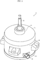
- FIG. 1 is a perspective view of molded motor 1 according to Embodiment 1.
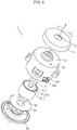
- FIG. 2 is an exploded perspective view of molded motor 1.
- FIG. 3 is a cross-sectional view of molded motor 1.
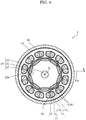
- FIG. 4 is a cross-sectional view of molded motor 1 taken along line IV-IV in FIG. 34. It should be noted that in FIGS.
- a direction in which rotary shaft 21 included in rotor 20 extends is defined as axial direction X
- a direction that extends from shaft center C about shaft center C of rotary shaft 21 is defined as radial direction Y
- a circumferential direction centered on shaft center C is defined as circumferential direction Z.
- hatching is omitted for convenience of illustration of the core portion of stator core 11 and the core portion of rotor core 22 in order to make the drawing easy to see.
- molded motor 1 includes stator 10, rotor 20 arranged to face stator 10, mold resin 30 covering stator 10, and lead bush 40 attached to mold resin 30.
- Molded motor 1 further includes first bearing 51 and second bearing 52, first bracket 61 and second bracket 62, first metal cover 71 and second metal cover 72, and circuit board 80.
- mold resin 30 In molded motor 1, mold resin 30, first bracket 61, second bracket 62, and first metal cover 71 configure the outer shell of molded motor 1.
- Molded motor 1 in the present embodiment is a brushless motor without using a brush.
- molded motor 1 in the present embodiment is an inner rotor type motor in which rotor 20 is arranged inside stator 10. It should be noted that the present disclosure can also be applied to an outer rotor type motor in which the rotor is arranged outside the stator.
- Stator 10 (stational element) is arranged so as to surround rotor 20 via a small air gap between stator 10 and rotor 20.
- Stator 10 includes stator core 11, coil 12, and insulator 13.
- Stator core 11 is an annular iron core that generates a magnetic force for rotating rotor 20.
- stator core 11 is, for example, a stacked body in which a plurality of electromagnetic steel plates are stacked in the longitudinal direction (axial direction X) of rotary shaft 21 included in rotor 20. It should be noted that stator core 11 is not limited to the stacked body and may be a bulk body made of a magnetic material.
- stator core 11 includes yoke 11a formed in an annular shape so as to surround rotor 20, and a plurality of teeth 11b protruding from yoke 11a toward rotary shaft 21 in a convex shape.
- stator core 11 is provided with twelve teeth 11b.
- Yoke 11a is a back yoke formed outside each tooth 11b.
- yoke 11a is formed in an annular shape about shaft center C.
- the plurality of teeth 11b are arranged at equal intervals in circumferential direction Z, respectively, while forming slots 14 which are openings between them.
- extending portions 11b1 extending on both sides in circumferential direction Z are formed at the extending tip portions where each tooth 11b is extended.
- the inner peripheral surface located at the tip portion of tooth 11b including this extending portion 11b1 serves as a magnetic pole surface facing the outer peripheral surface of rotor 20. It should be noted that in two adjacent teeth 11b, a gap (slot opening) exists between extending portion 11b1 of one tooth 11b and extending portion 11b1 of the other tooth 11b.
- Coil 12 is a winding coil wound around stator core 11 via insulator 13. Specifically, as shown in FIG. 4 , coil 12 is wound around each of the plurality of teeth 11b included in stator core 11. In addition, as shown in FIG. 3 , each coil 12 includes coil end 12a protruding from stator core 11 to both sides of stator core 11 along the longitudinal direction (axial direction X) of rotary shaft 21. That is, coil end 12a is a portion of coil 12 that protrudes and sticks out from stator core 11 in axial direction X. It should be noted that 12 coils 12 are used in the present embodiment. Therefore, the number of slots of molded motor 1 is 12.
- molded motor 1 is a high output motor having an output of 750 W or more in the present embodiment.
- coil 12 having a wire diameter ⁇ of 0.3 mm or more is used.
- wire diameter ⁇ of coil 12 is 0.5 mm to 1.0 mm.
- the plurality of coils 12 are configured by each unit coil of three phases of U phase, V phase, and W phase whose phases are electrically different from each other by 120 degrees. That is, each coil 12 wound around tooth 11b is energized and driven by three-phase alternating current that is energized in units of U-phase, V-phase, and W-phase, respectively. It should be noted that coils 12 of each phase are connected by a crossover wire (not shown). The crossover wire is arranged on the outer peripheral wall portion of insulator 13 or the like. Coil 12 and the crossover wire are configured by a conductor wire serving as a core wire and an insulator for insulating and coating the surface of the conductor wire.
- circuit board 80 ends of each phase of coil 12 are connected by winding connection portions included in circuit board 80.
- pattern wirings for electrically connecting the plurality of coils 12 for each of the U-phase, V-phase, and W-phase are formed on circuit board 80, and the ends of coils 12 for each phase are electrically connected with pattern wirings of circuit board 80 by solder or the like.
- circuit board 80 includes an opening through which rotary shaft 21 is loosely inserted at a center portion, and has, for example, an annular shape (a donut shape), a fan shape (an arc shape), a C shape, or the like.
- each phase of coil 12 may be configured to use a connecting member made of a conductive material in addition to the configuration using the circuit board. It should be noted that the present disclosure can be applied to any structure as long as the lead wire is inserted inside the enclosure of the motor regardless of the specifications of the motor.
- insulator 13 is an insulating frame that covers stator core 11. Specifically, insulator 13 covers teeth 11b included in stator core 11, and is provided for each tooth 11b. Insulator 13 is made of, for example, an insulating resin material such as PBT.
- Rotor 20 (rotational element) arranged inside stator 10 rotates due to the magnetic force generated in stator 10.
- rotor 20 includes rotary shaft 21, and rotates about shaft center C of rotary shaft 21 as a rotation center.
- Rotary shaft 21 extends along axial direction X.
- Rotor 20 has a configuration in which a plurality of N poles and S poles are repeatedly present in circumferential direction Z.
- rotor 20 is a permanent magnet embedded rotor (IPM rotor), and includes rotor core (rotational element iron core) 22 and permanent magnet 23 that is inserted into each of a plurality of magnet insertion holes 22 formed in rotor core 22.
- IPM rotor permanent magnet embedded rotor
- rotor core 22 is a substantially columnar stacked body in which a plurality of electromagnetic steel plates are stacked in the longitudinal direction (axial direction X) of rotary shaft 21.
- rotor core 22 is formed with a plurality of magnet insertion holes 22a penetrating in axial direction X at equal intervals in circumferential direction Z as shown in FIG. 4 .
- One permanent magnet 23 is inserted into each magnet insertion hole 22a.
- the number of magnetic poles is 10, and ten permanent magnets 23 are arranged so that the S-pole and N-pole are alternately located in circumferential direction Z.
- Rotary shaft 21 is fixed to the center of rotor core 22.
- Rotary shaft 21 is a shaft such as a metal rod, and penetrates rotor core 22 so as to extend on both sides of rotor core 22.
- Rotary shaft 21 is fixed to rotor core 22 by, for example, being press-fitted or shrink-fitted into a center hole of rotor core 22.
- first bearing 51 and second bearing 52 are bearings that rotatably support rotary shaft 21.
- First bearing 51 is fixed to first bracket 61 made of a metal.
- second bearing 52 is fixed to second bracket 62 made of a metal.
- rotary shaft 21 penetrates first bearing 51, and although not shown, a load such as a rotary fan is attached to a portion of rotary shaft 21 that protrudes from first bearing 51 to the outside.
- a portion of rotary shaft 21 to which a load such as a rotary fan is attached is also referred to as output shaft 21a.
- Rotor 20 configured in this way is rotated by the magnetic flux generated in stator 10. Specifically, when electric power is supplied from circuit board 80 to coil 12 included in stator 10, a field current flows through coil 12 and a magnetic flux is generated in stator core 11. The magnetic force generated by the interaction between the magnetic flux generated by this stator core 11 and the magnetic flux generated by permanent magnet 23 included in rotor 20 serves as a torque for rotating rotor 20, and rotor 20 rotates.
- stator 10 is covered with mold resin 30.
- mold resin 30 covers stator core 11, coil 12, and insulator 13 except for the inner peripheral surface of teeth 11b included in stator core 11.
- Mold resin 30 is made of a resin material such as unsaturated polyester (BMC).
- mold resin 30 configures an enclosure which is a part of the outer shell of molded motor 1. That is, mold resin 30 that covers stator 10 configures a housing that encloses rotor 20. Specifically, mold resin 30 is a body portion of molded motor 1 and is formed in a substantially cylindrical shape.
- first bracket 61 is provided on one edge portion of mold resin 30 so as to close one opening of mold resin 30.
- second bracket 62 is provided on the other edge portion of mold resin 30 so as to close the other opening of mold resin 30.
- First bracket 61 and second bracket 62 are made of, for example, iron, but are not limited thereto.
- the overall diameter of first bracket 61 is smaller than the overall diameter of second bracket 62 in the present embodiment, but the present invention is not limited thereto.
- lead bush 40 is attached to mold resin 30.
- mold resin 30 and lead bush 40 will be described using FIGS. 5 to 8 with reference to FIGS. 1 to 4 .
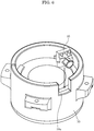
- FIG. 5 is a diagram showing molded motor 1 according to Embodiment 1 with lead bush 40 removed.
- FIG. 6 is a diagram showing a state in which lead bush 40 is attached to mold resin 30. It should be noted that the vertical direction (axial direction X) of molded motor 1 in FIG. 6 is shown in reverse to FIGS. 1 and 5 in order to make it easier to understand how lead bush 40 is attached to mold resin 30.
- FIG. 7 is a diagram showing the configuration of lead bush 40 used in molded motor 1, wherein (a) is a front view, (b) is a side view, and (c) is a top view. It should be noted that metal member 41 is hatched for convenience in FIG. 7 .
- (b) in FIG. 7 shows a cross-section of metal member 41 taken along line B-B of (a) in FIG. 7
- (c) in FIG. 7 shows a cross-section of metal member 41 taken along line C-C of (b) in FIG. 7 .
- FIG. 8 is a cross-sectional view showing a peripheral structure of mold resin 30 and lead bush 40 in molded motor 1.
- mold resin 30 includes first opening 30a.
- Lead bush 40 is attached to this first opening 30a.
- first opening 30a is formed so as to cut out a part of the outer wall portion of mold resin 30.
- first opening 30a is formed so as to cut out a part of the opening end portion of mold resin 30 along shaft center C.
- the shape of first opening 30a is a rectangular shape in a side view of mold resin 30.
- Lead bush 40 is attached to mold resin 30 by inserting it into this first opening 30a along shaft center C.
- lead bush 40 is provided with recess 40b for accommodating the side wall portion of mold resin 30 as shown in FIGS. 7 and 8 , and lead bush 40 can be fixed to mold resin 30 by fitting this recess 40b into the side wall potion of mold resin 30 in first opening 30a as shown in FIG. 8 .
- lead bush 40 is a lead portion for drawing out electric wire 90 connected to circuit board 80.
- lead bush 40 is a protective member that protects electric wire 90 inserted through lead bush 40.
- Lead bush 40 is also called a cable bushing or a bushing.
- Electric power for energizing coil 12 wound around stator 10 is supplied to electric wire 90. That is, electric power is supplied to circuit board 80 via electric wire 90.
- Electric wire 90 is a power supply line and is, for example, a lead wire.
- electric wire 90 is configured by three lead wires. Each lead wire is configured by a conductor wire serving as a core wire and an insulator for insulating and coating the surface of the conductor wire.
- the power for energizing coil 12 directly or indirectly is supplied to wire 90, as described above.
- a signal for controlling the motor may be supplied to electric wire 90 from a control device outside the motor.
- lead bush 40 is formed with an insertion through-hole 40a for drawing out electric wire 90. That is, electric wire 90 is inserted through insertion through-hole 40a.
- Insertion through-hole 40a is, for example, a cylindrical through hole. In this case, the shape (opening shape) of insertion through-hole 40a is circular.
- the main body of lead bush 40 (lead bush main body) is made of a non-metallic material such as a resin material or a ceramic.
- lead bush 40 is made of, for example, a hard insulating resin material or an insulating resin material having rubber elasticity such as an elastomer.
- the main body of lead bush 40 is made of PBT.
- lead bush 40 includes metal member 41.
- Metal member 41 is attached to lead bush 40.
- metal member 41 is embedded in lead bush 40.
- Lead bush 40 in which metal member 41 is embedded can be manufactured by, for example, integral molding such as insert molding.
- Metal member 41 is formed by a metal plate. Specifically, metal member 41 is a tabular flat metal plate. As an example, the metal material forming metal member 41 is iron, aluminum, copper or stainless steel.
- Second opening 41a is formed in metal member 41.
- Second opening 41a is a through hole for drawing out electric wire 90.
- Electric wire 90 is inserted into second opening 41a.
- the shape of second opening 41a is circular in a side view of mold resin 30.
- Second opening 41a is smaller than first opening 30a formed in mold resin 30, and larger than insertion through-hole 40a formed in lead bush 40. That is, when insertion through-hole 40a formed in lead bush 40 is viewed from the front (that is, in the side view of mold resin 30), the opening area of second opening 41a formed in metal member 41 is smaller than the opening area of first opening 30a formed in mold resin 30, and larger than the opening area of insertion through-hole 40a formed in lead bush 40.
- the entire circumference of the opening edge of second opening 41a formed in metal member 41 is located inside the entire circumference of the opening edge of first opening 30a formed in mold resin 30, and is located outside the entire circumference of the opening edge of insertion through-hole 40a formed in lead bush 40.
- the opening width of first opening 30a is W1
- the opening width of second opening 41a is W2
- the opening width of insertion through-hole 40a is W3
- the relationship of W3 ⁇ W2 ⁇ W1 is satisfied.
- lead bush 40 including metal member 41 having such a configuration even if coil 12 wound around stator 10 abnormally generates heat or the like and a layer short circuit occurs to cause ignition inside mold resin 30 and the resin portion of lead bush 40 melts out, metal member 41 which is a non-combustible material will remain without burning. With this, since metal member 41 blocks fire from first opening 30a formed in mold resin 30 to which lead bush 40 is attached to the outside of mold resin 30, it is possible to prevent fire from spouting from molded motor 1. As a result, it is possible to suppress the spread of the fire generated in molded motor 1.
- metal member 41 covers first opening 30a formed in mold resin 30 in the present embodiment.
- metal member 41 is arranged so that the outer shape of metal member 41 covers first opening 30a formed in mold resin 30 in the direction intersecting with the longitudinal direction (axial direction X) of rotary shaft 21.
- the direction intersecting with the longitudinal direction of rotary shaft 21 means a radial direction centered on shaft center C of rotary shaft 21 in a plane orthogonal to the longitudinal direction of rotary shaft 21.
- first opening 30a with metal member 41 by covering first opening 30a formed in mold resin 30 except for a portion corresponding to the opening area of second opening 41a. With this, even if ignition occurs inside mold resin 30 due to a layer short circuit or the like, it is possible to further suppress fire from spouting from first opening 30a.
- mold resin 30 is provided with first metal cover 71 and second metal cover 72 as shown in FIG. 3 .
- first metal cover 71 and second metal cover 72 includes a portion provided in circumferential direction Z of mold resin 30 so as to cover coil end 12a positioned at the end portion of coil 12 wound around stator 10.
- First metal cover 71 is an outer cover made of a metal, and is mounted on the first bracket 61 side of mold resin 30 (the output shaft 21a side). First metal cover 71 surrounds coil end 12a and insulator 13 positioned on the output shaft 21a side. In addition, first metal cover 71 has a hollow cup shape having an opening at the center. A part of first bracket 61 positioned on the output shaft 21a side is configured to penetrate the opening included in this first metal cover 71.
- Second metal cover 72 is an inner cover made of a metal, and is configured to surround the outer periphery of stator 10. Specifically, second metal cover 72 surrounds coil end 12a and insulator 13, which are positioned on the side opposite to the output shaft 21a side, and stator core 11. In the present embodiment, second metal cover 72 is a cylindrical body that has a cylindrical shape and is open on both sides.
- first metal cover 71 and second metal cover 72 By covering each of coil end 12a with first metal cover 71 and second metal cover 72, even when the ignition occurs inside the molding resin 30 due to a layer short circuit or the like, fire is blocked by first metal cover 71 and second metal cover 72. With this, it is possible to further suppress fire from spouting from molded motor 1.
- first metal cover 71 or second metal cover 72 may be provided, but by providing both first metal cover 71 and second metal cover 72, it is possible to reliably prevent fire from spouting to the outside of molded motor 1.
- molded motor 1 of the present embodiment even if ignition occurs inside mold resin 30 due to abnormal heat generation of the coil or the like, it is possible to suppress fire from spouting from the place where lead bush 40 is attached in mold resin 30 to the outside.
- metal member 41 is fixed to lead bush 40 so as to be positioned outside mold resin 30 in the present embodiment, but it is not limited thereto.
- metal member 41 may be fixed to lead bush 40 so as to be positioned inside mold resin 30, or may be fixed to lead bush 40 so as to be positioned at first opening 30a (middle side) formed in mold resin 30.
- metal member 41 is a flat metal plate in the present embodiment, but it is not limited thereto.
- metal member 41 may be a curved metal plate like lead bush 40 shown in FIG. 9 .
- the metal plate may be curved along the shape of the side wall portion formed by mold resin 30.
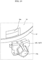
- metal member 41A may include a positioning portion 41b for attaching metal member 41A to mold resin 30 like lead bush 40A shown in FIG. 10 .
- metal member 41A includes a hook portion that can be hooked on a part of mold resin 30 as positioning portion 41b.
- metal member 41A includes, as a positioning portion 41b (hook portion), a bent portion formed by bending both end portions of a rectangular metal plate in a brim shape. This positioning portion 41b (bent portion) is locked to the inner surface of the side wall portion formed by mold resin 30 as shown in FIG. 10 .
- positioning portion 41b included in metal member 41A functions as a fall prevention structure for metal member 41A. With this, it is possible to further suppress fire from spouting from first opening 30a.
- FIG. 12 is a diagram showing the configuration of lead bush 40B used in molded motor 2 according to Embodiment 2, where (a) in FIG. 12 is a front view, (b) in FIG. 12 is a side view, and (c) in FIG. 12 is a top view. It should be noted that also in FIG. 12 , metal member 41 is hatched for convenience. It should be noted that (b) in FIG. 12 shows a cross-section of metal member 41 taken along line B-B of (a) in FIG. 12 , and (c) in FIG. 12 shows a cross-section of metal member 41 taken along line C-C of (b) in FIG. 12 . In addition, FIG. 13 is an enlarged cross-sectional view of a main part of molded motor 2 according to Embodiment 2.
- metal member 41 of lead bush 40 is configured by one metal plate, but in molded motor 2 according to the present embodiment as shown in FIGS. 12 and 13 , metal member 41 included in lead bush 40B is configured by a plurality of metal plates. It should be noted that in the description of Embodiment 2 and the subsequent embodiments, the same components as those in Embodiment 1 will be designated by the same reference numerals and the description of each component will be incorporated.
- metal member 41 is configured by a plurality of metal plates covering first opening 30a formed in mold resin 30.
- the plurality of metal plates configuring metal member 41 are arranged so as to overlap each other. More specifically, the plurality of metal plates are arranged such that second opening 41a included in each of the plurality of metal plates overlap each other. It should be noted that metal member 41 is configured by two metal plates in the present embodiment.
- each of second openings 41a formed in a plurality of metal plates configuring metal member 41 is smaller than first opening 30a formed in mold resin 30, and is larger than insertion through-hole 40a formed in lead bush 40.
- metal member 41 is configured by a plurality of metal plates in the present embodiment. That is, first opening 30a formed in mold resin 30 is closed by the metal plate having a double structure. With this, it is possible to further suppress fire from spouting from first opening 30a formed in mold resin 30 to the outside of mold resin 30.
- molded motor 2 in the present embodiment has the same configuration as molded motor 1 in Embodiment 1 described above except that metal member 41 is configured by a plurality of metal plates.
- both of the two metal plates configuring metal member 41 are flat, but the present invention is not limited thereto.
- one of the two metal plates configuring metal member 41 may be curved as in lead bush 40B shown in FIG. 14A . It should be noted that both of the two metal plates configuring metal member 41 may be curved.
- metal member 41B may have a positioning portion (hook portion) 41b for attaching metal member 41B to mold resin 30 similar to metal member 41A shown in FIG. 10 . That is, metal member 41B may have a fall prevention structure.
- FIG. 15 is a cross-sectional view showing the peripheral structure of mold resin 30 and lead bush 40C in molded motor 3 according to Embodiment 3.
- FIG. 16 is a perspective view of metal member 41C included in lead bush 40C used in molded motor 3
- FIG. 17 is a top view of metal member 41C.
- lead bush 40C is a connector type, and includes protruding portion 41c that protrudes outward from the side wall portion of mold resin 30.
- Insertion through-hole 40a formed in lead bush 40C in the present embodiment is a small hole for preventing electric wire 90 from moving.
- three electric wires 90 are inserted through lead bush 40C, three insertion through-holes 40a are provided. Electric wire 90 is inserted into each of insertion through-holes 40a. Electric wire 90 inserted into insertion through-hole 40a is held by lead bush 40C.
- metal member 41C of lead bush 40C in the present embodiment is a metal cover that covers the outer surface of protruding portion 41c included in lead bush 40C.
- the metal cover is made of, for example, iron or the like.
- Metal member 41C which is a metal cover, includes second opening 41a. As shown in FIGS. 16 and 17 , the shape of second opening 41a is rectangular in a front view seen in radial direction Y. Also in the present embodiment, second opening 41a is smaller than first opening 30a formed in mold resin 30 and larger than each insertion through-hole 40a included in lead bush 40C. Specifically, second opening 41a surrounds three insertion through-holes 40a included in lead bush 40C.
- metal member 41C includes positioning portion 41b for attaching metal member 41C to mold resin 30 in lead bush 40C in the present embodiment.
- metal member 41C includes a hook portion that is hooked on a part of mold resin 30 as positioning portion 41b. More specifically, as shown in FIGS. 16 and 17 , metal member 41C has a bent portion formed by bending a part of the metal cover into a brim shape as positioning portion 41b (hook portion). As shown in FIG. 15 , this positioning portion 41b (bent portion) is housed in recess 30b provided in the side wall portion of mold resin 30 and is locked to the inner surface of recess 30b.
- positioning portion 41b included in metal member 41C functions as a fall prevention structure for metal member 41C, and thus it is possible to further suppress fire from spouting from first opening 30a.
- molded motor 3 has the same configuration as the molded motors 1 and 2 according to Embodiments 1 and 2 described above except for the above-described features.
- FIG. 18 is a cross-sectional view of molded motor 4 according to Embodiment 4.
- FIG. 19 is a diagram showing molded motor 4 according to Embodiment 4 with lead bush 40D removed.
- FIGS. 20 and 21 are cross-sectional views showing the peripheral structure of mold resin 30 and lead bushes 40D and 40E in molded motor 4 according to Embodiment 4.
- molded motor 4 includes stator 10, rotor 20 arranged to face stator 10, mold resin 30 covering stator 10, and lead bush 40D made of a ceramic.
- Stator 10 includes stator core 11, coil 12, and insulator 13.
- Coil 12 is a winding coil wound around stator core 11 via insulator 13.
- Rotor 20 includes rotary shaft 21.
- Rotor 20 includes rotor core 22 in which a plurality of permanent magnets 23 are embedded.
- Mold resin 30 includes first opening 30a. Lead bush 40D is attached to this first opening 30a.
- Lead bush 40D is a drawer portion for drawing out electric wire 90.
- Lead bush 40D is formed with an insertion through-hole 40a for drawing out electric wire 90.
- Insertion through-hole 40a is smaller than first opening 30a. That is, when insertion through-hole 40a formed in lead bush 40D is viewed from the front, that is, in radial direction Y intersecting with rotary shaft 21, the opening area of insertion through-hole 40a is smaller than the opening area of first opening 30a formed in mold resin 30.
- the entire circumference of the opening edge of insertion through-hole 40a formed in lead bush 40D is located inside the entire circumference of the opening edge of first opening 30a formed in mold resin 30.
- the opening width of first opening 30a is W11 and the opening width of insertion through-hole 40a is W13 as shown in FIG. 20 , the relationship of W13 ⁇ W11 is satisfied.
- lead bush 40E includes inner opening 40c and outer opening 40d for drawing out electric wires 90 as shown in FIG. 21 .
- Inner opening 40c is located inside molded motor 4 in lead bush 40E attached to mold resin 30.
- Outer opening 40d is located outside molded motor 4 in lead bush 40E attached to mold resin 30.
- insertion through-hole 40a formed in lead bush 40E includes inner opening 40c that is open to the inside of molded motor 4, that is, the rotary shaft 21 side, and outer opening 40d that is open to the outside of molded motor 4, that is, the opposite side to the side where rotary shaft 21 is located.
- Inner opening 40c is smaller than first opening 30a and larger than outer opening 40d. That is, when insertion through-hole 40a formed in lead bush 40E is viewed from the front, that is, in radial direction Y intersecting with rotary shaft 21, the opening area of inner opening 40c included in insertion through-hole 40a formed inside mold resin 30 is smaller than the opening area of first opening 30a formed in mold resin 30 and larger than the opening area of outer opening 40d included in insertion through-hole 40a formed outside mold resin 30.
- the entire circumference of the opening edge of inner opening 40c formed inside molded motor 4 in lead bush 40E is located inside the entire circumference of the opening edge of first opening 30a formed in mold resin 30, and is located outside the entire circumference of the opening edge of outer opening 40d formed outside molded motor 4 in lead bush 40E.
- the opening width of first opening 30a is W21
- the opening width of inner opening 40c included in insertion through-hole 40a is W22
- the opening width of outer opening 40d included in insertion through-hole 40a is W23, as shown in FIG. 21 , the relationship of W23 ⁇ W22 ⁇ W21 is satisfied.
- This configuration facilitates the work of passing electric wire 90 from the inside to the outside of lead bush 40E in molded motor 4.
- ceramic lead bushes 40D and 40E having the configuration described above, even if coil 12 wound around stator 10 abnormally generates heat or the like and a layer short circuit occurs to cause ignition inside mold resin 30, lead bushes 40D and 40E made of a ceramic, which is a non-combustible material, will remain without burning. With this, since ceramic lead bushes 40D and 40E block fire from first opening 30a formed in mold resin 30 to which lead bushes 40D and 40E are attached to the outside of mold resin 30, it is possible to prevent fire from spouting from molded motor 4. As a result, it is possible to suppress the spread of the fire generated in molded motor 4.
- second openings 41a included in metal members 41, 41A and 41B are circular holes in Embodiments 1 to 3 described above, the invention is not limited thereto, and the metal members may be in a cutout shape in which a part of the metal members is cut out. That is, second opening 41a is not limited to a closed hole, and may be a partially opened hole.
- metal members 41 and 41A are embedded inside the main body of lead bush 40 in Embodiments 1 and 2 described above, but the present invention is not limited thereto.
- the metal member may be fixed to lead bush 40 by forming a gap in a part of lead bush 40 and inserting the metal member (metal plate) into this gap.
- the number of magnetic poles of rotor 20 is 10 (that is, the number of permanent magnets 23 is 10) in each of Embodiments 1 to 4 described above, but the number is not limited thereto. Any number of magnetic poles of rotor 20 can be applied.
- the molded motor according to the present disclosure can be used as a motor in various fields including a fan motor used in an air conditioner and the like.
Landscapes
- Engineering & Computer Science (AREA)
- Power Engineering (AREA)
- Motor Or Generator Frames (AREA)
Abstract
Description
- The present disclosure relates to a molded motor.
- Conventionally, a molded motor in which a stator is covered with a mold resin is known (Patent Literature 1 (PTL 1)). For example, a molded motor includes a stator, a rotor disposed inside the stator, a mold resin that covers the stator, and a printed circuit board to which coils included in the stator are connected. In a molded motor, a plurality of lead wires connected to a printed circuit board are drawn out of the motor via a lead bush attached to an opening of a side wall portion made of a mold resin.
- In recent years, as the output of molded motors has increased, the heat generated by the coils wound around the stator core has increased. Thus, there is a problem that the mold resin covering the coils is thermally deteriorated.
- Therefore, in order to suppress heat deterioration of the mold resin, it has been proposed to use an epoxy resin in which fillers having a high thermal conductivity are contained as a mold resin (Patent Literature 2 (PTL 2)). Citation List
-
- PTL 1: International Patent Publication No.
2012/101976 - PTL 2:
Japanese Unexamined Patent Application Publication No. 2004-143368 - However, when a coil abnormally heats up by an excessive amount of current flowing in the coil included in the stator or the like, there is a possibility that a layer short circuit may occur in which the insulating material that insulates and coats the surface of the conductive wire forming the coil is melted and the conductive wires forming the coil are short-circuited. In addition, sparks may occur when a layer short circuit occurs.
- In this case, if the coil is disconnected, no current will flow through the coil, so that abnormal heat generation of the coil can be avoided. However, in a high-output molded motor, the wire diameter of the coil included in the stator is large (for example, ϕ0.3 mm or more), so that the coil is less likely to be disconnected even if the coil abnormally heats up. For this reason, there is a high possibility that a layer short circuit will occur in a high-output molded motor.
- On the other hand, when the temperature of the interior of the motor is increased due to heat generation of the coil or the like, flammable gas is generated from the resin components such as an insulator interposed between the lead bush or the stator core and the coil.
- In this way, if a layer short circuit occurs and sparks are generated when flammable gas is present inside the motor, the sparks may ignite the gas.
- Particularly, when the flammable gas is generated in the vicinity of the lead bush, the spark is likely to occur between the lead wires which are inserted through the lead bush due to the air (oxygen) flowing in the vicinity of the lead bush, and the possibility to ignite increases.
- At this time, if the lead bush is made of resin, the lead bush will melt due to ignition. For example, a lead bush made of polybutylene terephthalate (hereinafter referred to as "PBT") starts to melt at about 230 °C. When the lead bush is melted in this way, there is a possibility that the ignited fire will spout from the melted portion of the lead bush (that is, the opening of the side wall portion formed by the mold resin) to the outside of the motor to spread the fire.
- In addition, when the temperature inside the motor continues to be high, the combustible gas is filled inside the motor and the concentration (pressure) of the gas increases, so that the possibility for an ignited fire to spout to the outside increases. At this time, a fire is likely to spout to the outside from the lead bush, which is weaker in strength than the mold resin.
- The present disclosure has been made in order to solve such a problem, and an object of the present disclosure is to provide a molded motor that can suppress fire from spouting from the place where the lead bush in the mold resin is attached even when ignition occurs inside the mold resin due to abnormal heat generation or the like of the coil included in the stator.
- To achieve the above object, one aspect of the molded motor according to the present disclosure includes: a stator that includes a stator core and a coil wound around the stator core via an insulator; a rotor that is arranged to face the stator and includes a rotor core and a rotary shaft; a mold resin that includes a first opening and covers the stator; and a lead bush that is attached to the first opening and includes an insertion through-hole for drawing out an electric wire, wherein the lead bush includes a metal member including a second opening for drawing out the electric wire, the second opening being smaller than the first opening and larger than the insertion through-hole.
- In addition, another aspect of the molded motor according to the present disclosure includes: a stator that includes a stator core and a coil wound around the stator core via an insulator; a rotor that is arranged to face the stator and includes a rotor core and a rotary shaft; a mold resin that includes a first opening and covers the stator; and a lead bush made of a ceramic that is attached to the first opening and has an insertion through-hole for drawing out an electric wire, wherein the insertion through-hole is smaller than the first opening.
- According to the present disclosure, even when the fire occurs inside the mold resin, it is possible to suppress fire from spouting to the outside from the portion where the lead bush in the mold resin is attached.
-
-
FIG. 1 is a perspective view of a molded motor according toEmbodiment 1. -
FIG. 2 is an exploded perspective view of the molded motor according toEmbodiment 1. -
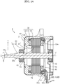
FIG. 3 is a cross-sectional view of the molded motor according toEmbodiment 1. -
FIG. 4 is a cross-sectional view of the molded motor according toEmbodiment 1 taken along line IV-IV inFIG. 3 . -
FIG. 5 is a diagram showing the molded motor according toEmbodiment 1 with a lead bush removed. -
FIG. 6 is a diagram showing a state in which the lead bush is attached to the mold resin in the molded motor according toEmbodiment 1. -
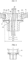
FIG. 7 illustrates a front view of a lead bush used in the molded motor according to Embodiment 1 in (a), a side view of the lead bush in (b), and a top view of the lead bush in (c). -
FIG. 8 is a cross-sectional view showing a peripheral structure of the mold resin and the lead bush in the molded motor according toEmbodiment 1. -
FIG. 9 is a diagram showing a configuration of a lead bush of a first variation used in the molded motor according toEmbodiment 1. -
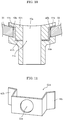
FIG. 10 is a diagram showing a configuration of a lead bush of a second variation used in the molded motor according toEmbodiment 1. -
FIG. 11 is a diagram showing a configuration of a metal member in the lead bush of the second variation used in the molded motor according toEmbodiment 1. -
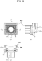
FIG. 12 illustrates a front view of a lead bush used in the molded motor according toEmbodiment 2 in (a), a side view of the lead bush in (b), and a top view of the lead bush in (c). -
FIG. 13 is a cross-sectional view showing a peripheral structure of a mold resin and a lead bush in the molded motor according toEmbodiment 2. -
FIG. 14A is a diagram showing a configuration of a lead bush in a variation used in the molded motor according toEmbodiment 2. -
FIG. 14B is a diagram showing a configuration of a metal member in a lead bush in a variation used in the molded motor according toEmbodiment 2. -
FIG. 15 is a cross-sectional view showing a peripheral structure of a mold resin and a lead bush in the molded motor according toEmbodiment 3. -
FIG. 16 is a perspective view of a metal member included in the lead bush used in the molded motor according to Embodiment 3. -
FIG. 17 is a top view of a metal member included in a lead bush used in the molded motor according to Embodiment 3. -
FIG. 18 is a cross-sectional view of the molded motor according toEmbodiment 4. -
FIG. 19 is a diagram showing a molded motor according toEmbodiment 4 with a lead bush removed. -
FIG. 20 is a cross-sectional view showing a peripheral structure of a mold resin and a lead bush in the molded motor according toEmbodiment 4. -
FIG. 21 is a cross-sectional view showing a peripheral structure of a mold resin and another lead bush in the molded motor according toEmbodiment 4. - Hereinafter, embodiments of the present disclosure will be described. It should be noted that each of the embodiments described below shows a specific example of the present disclosure. Therefore, the numerical values, the components, the arrangement positions and connection forms of the components, the steps, the order of the steps, and the like shown in the following embodiments are examples, and are not intended to limit the present disclosure. Therefore, among the components in the following embodiments, the components that are not described in the independent claims showing the highest concept of the present disclosure will be described as arbitrary components.
- In addition, each drawing is a schematic view and is not necessarily strictly illustrated. It should be noted that in each drawing, the same reference numerals are given to substantially the same configurations, and overlapping description will be omitted or simplified.
- First, the overall structure of molded
motor 1 according toEmbodiment 1 will be described with reference toFIGS. 1 to 4 .FIG. 1 is a perspective view of moldedmotor 1 according toEmbodiment 1.FIG. 2 is an exploded perspective view of moldedmotor 1.FIG. 3 is a cross-sectional view of moldedmotor 1.FIG. 4 is a cross-sectional view of moldedmotor 1 taken along line IV-IV in FIG. 34. It should be noted that inFIGS. 2 to 4 , a direction in whichrotary shaft 21 included inrotor 20 extends is defined as axial direction X, a direction that extends from shaft center C about shaft center C ofrotary shaft 21 is defined as radial direction Y, and a circumferential direction centered on shaft center C is defined as circumferential direction Z. In addition, inFIG. 4 , hatching is omitted for convenience of illustration of the core portion ofstator core 11 and the core portion ofrotor core 22 in order to make the drawing easy to see. - As shown in
FIGS. 1 to 3 , moldedmotor 1 includesstator 10,rotor 20 arranged to facestator 10,mold resin 30 coveringstator 10, and leadbush 40 attached to moldresin 30. - Molded
motor 1 further includesfirst bearing 51 andsecond bearing 52,first bracket 61 andsecond bracket 62,first metal cover 71 andsecond metal cover 72, andcircuit board 80. - In molded
motor 1,mold resin 30,first bracket 61,second bracket 62, andfirst metal cover 71 configure the outer shell of moldedmotor 1. - Molded
motor 1 in the present embodiment is a brushless motor without using a brush. In addition, moldedmotor 1 in the present embodiment is an inner rotor type motor in whichrotor 20 is arranged insidestator 10. It should be noted that the present disclosure can also be applied to an outer rotor type motor in which the rotor is arranged outside the stator. - Stator 10 (stational element) is arranged so as to surround
rotor 20 via a small air gap betweenstator 10 androtor 20.Stator 10 includesstator core 11,coil 12, andinsulator 13. -
Stator core 11 is an annular iron core that generates a magnetic force for rotatingrotor 20. As shown inFIG. 3 ,stator core 11 is, for example, a stacked body in which a plurality of electromagnetic steel plates are stacked in the longitudinal direction (axial direction X) ofrotary shaft 21 included inrotor 20. It should be noted thatstator core 11 is not limited to the stacked body and may be a bulk body made of a magnetic material. - As shown in
FIG. 4 ,stator core 11 includes yoke 11a formed in an annular shape so as to surroundrotor 20, and a plurality of teeth 11b protruding from yoke 11a towardrotary shaft 21 in a convex shape. In the present embodiment,stator core 11 is provided with twelve teeth 11b. - Yoke 11a is a back yoke formed outside each tooth 11b. In the present embodiment, yoke 11a is formed in an annular shape about shaft center C.
- The plurality of teeth 11b are arranged at equal intervals in circumferential direction Z, respectively, while forming
slots 14 which are openings between them. In addition, extending portions 11b1 extending on both sides in circumferential direction Z are formed at the extending tip portions where each tooth 11b is extended. The inner peripheral surface located at the tip portion of tooth 11b including this extending portion 11b1 serves as a magnetic pole surface facing the outer peripheral surface ofrotor 20. It should be noted that in two adjacent teeth 11b, a gap (slot opening) exists between extending portion 11b1 of one tooth 11b and extending portion 11b1 of the other tooth 11b. -
Coil 12 is a winding coil wound aroundstator core 11 viainsulator 13. Specifically, as shown inFIG. 4 ,coil 12 is wound around each of the plurality of teeth 11b included instator core 11. In addition, as shown inFIG. 3 , eachcoil 12 includescoil end 12a protruding fromstator core 11 to both sides ofstator core 11 along the longitudinal direction (axial direction X) ofrotary shaft 21. That is,coil end 12a is a portion ofcoil 12 that protrudes and sticks out fromstator core 11 in axial direction X. It should be noted that 12 coils 12 are used in the present embodiment. Therefore, the number of slots of moldedmotor 1 is 12. - In addition, molded
motor 1 is a high output motor having an output of 750 W or more in the present embodiment. For this reason,coil 12 having a wire diameter ϕ of 0.3 mm or more is used. As an example, wire diameter ϕ ofcoil 12 is 0.5 mm to 1.0 mm. - The plurality of
coils 12 are configured by each unit coil of three phases of U phase, V phase, and W phase whose phases are electrically different from each other by 120 degrees. That is, eachcoil 12 wound around tooth 11b is energized and driven by three-phase alternating current that is energized in units of U-phase, V-phase, and W-phase, respectively. It should be noted that coils 12 of each phase are connected by a crossover wire (not shown). The crossover wire is arranged on the outer peripheral wall portion ofinsulator 13 or the like.Coil 12 and the crossover wire are configured by a conductor wire serving as a core wire and an insulator for insulating and coating the surface of the conductor wire. - In addition, ends of each phase of
coil 12 are connected by winding connection portions included incircuit board 80. Specifically, pattern wirings for electrically connecting the plurality ofcoils 12 for each of the U-phase, V-phase, and W-phase are formed oncircuit board 80, and the ends ofcoils 12 for each phase are electrically connected with pattern wirings ofcircuit board 80 by solder or the like. It should be noted thatcircuit board 80 includes an opening through whichrotary shaft 21 is loosely inserted at a center portion, and has, for example, an annular shape (a donut shape), a fan shape (an arc shape), a C shape, or the like. - Alternatively, the terminal of each phase of
coil 12 may be configured to use a connecting member made of a conductive material in addition to the configuration using the circuit board. It should be noted that the present disclosure can be applied to any structure as long as the lead wire is inserted inside the enclosure of the motor regardless of the specifications of the motor. - As shown in
FIGS. 3 and4 ,insulator 13 is an insulating frame that coversstator core 11. Specifically,insulator 13 covers teeth 11b included instator core 11, and is provided for each tooth 11b.Insulator 13 is made of, for example, an insulating resin material such as PBT. - Rotor 20 (rotational element) arranged inside
stator 10 rotates due to the magnetic force generated instator 10. Specifically,rotor 20 includesrotary shaft 21, and rotates about shaft center C ofrotary shaft 21 as a rotation center.Rotary shaft 21 extends along axial direction X. -
Rotor 20 has a configuration in which a plurality of N poles and S poles are repeatedly present in circumferential direction Z. In the present embodiment,rotor 20 is a permanent magnet embedded rotor (IPM rotor), and includes rotor core (rotational element iron core) 22 andpermanent magnet 23 that is inserted into each of a plurality of magnet insertion holes 22 formed inrotor core 22. - As shown in
FIG. 3 ,rotor core 22 is a substantially columnar stacked body in which a plurality of electromagnetic steel plates are stacked in the longitudinal direction (axial direction X) ofrotary shaft 21. In addition,rotor core 22 is formed with a plurality ofmagnet insertion holes 22a penetrating in axial direction X at equal intervals in circumferential direction Z as shown inFIG. 4 . Onepermanent magnet 23 is inserted into eachmagnet insertion hole 22a. In the present embodiment, the number of magnetic poles is 10, and tenpermanent magnets 23 are arranged so that the S-pole and N-pole are alternately located in circumferential direction Z. -
Rotary shaft 21 is fixed to the center ofrotor core 22.Rotary shaft 21 is a shaft such as a metal rod, and penetratesrotor core 22 so as to extend on both sides ofrotor core 22.Rotary shaft 21 is fixed torotor core 22 by, for example, being press-fitted or shrink-fitted into a center hole ofrotor core 22. - As shown in
FIG. 3 ,rotary shaft 21 is held byfirst bearing 51 andsecond bearing 52. With this,rotor 20 is rotatable with respect tostator 10. As an example,first bearing 51 andsecond bearing 52 are bearings that rotatably supportrotary shaft 21. First bearing 51 is fixed tofirst bracket 61 made of a metal. In addition,second bearing 52 is fixed tosecond bracket 62 made of a metal. It should be noted thatrotary shaft 21 penetratesfirst bearing 51, and although not shown, a load such as a rotary fan is attached to a portion ofrotary shaft 21 that protrudes fromfirst bearing 51 to the outside. A portion ofrotary shaft 21 to which a load such as a rotary fan is attached is also referred to asoutput shaft 21a. -
Rotor 20 configured in this way is rotated by the magnetic flux generated instator 10. Specifically, when electric power is supplied fromcircuit board 80 tocoil 12 included instator 10, a field current flows throughcoil 12 and a magnetic flux is generated instator core 11. The magnetic force generated by the interaction between the magnetic flux generated by thisstator core 11 and the magnetic flux generated bypermanent magnet 23 included inrotor 20 serves as a torque for rotatingrotor 20, androtor 20 rotates. - As shown in
FIG. 3 ,stator 10 is covered withmold resin 30. Specifically,mold resin 30covers stator core 11,coil 12, andinsulator 13 except for the inner peripheral surface of teeth 11b included instator core 11.Mold resin 30 is made of a resin material such as unsaturated polyester (BMC). - In the present embodiment,
mold resin 30 configures an enclosure which is a part of the outer shell of moldedmotor 1. That is,mold resin 30 that coversstator 10 configures a housing that enclosesrotor 20. Specifically,mold resin 30 is a body portion of moldedmotor 1 and is formed in a substantially cylindrical shape. - It should be noted that
first bracket 61 is provided on one edge portion ofmold resin 30 so as to close one opening ofmold resin 30. In addition,second bracket 62 is provided on the other edge portion ofmold resin 30 so as to close the other opening ofmold resin 30.First bracket 61 andsecond bracket 62 are made of, for example, iron, but are not limited thereto. In addition, the overall diameter offirst bracket 61 is smaller than the overall diameter ofsecond bracket 62 in the present embodiment, but the present invention is not limited thereto. - As shown in
FIGS. 1 to 3 , leadbush 40 is attached to moldresin 30. Here, detailed configurations ofmold resin 30 andlead bush 40 will be described usingFIGS. 5 to 8 with reference toFIGS. 1 to 4 . -
FIG. 5 is a diagram showing moldedmotor 1 according toEmbodiment 1 withlead bush 40 removed.FIG. 6 is a diagram showing a state in which leadbush 40 is attached to moldresin 30. It should be noted that the vertical direction (axial direction X) of moldedmotor 1 inFIG. 6 is shown in reverse toFIGS. 1 and5 in order to make it easier to understand howlead bush 40 is attached to moldresin 30. -
FIG. 7 is a diagram showing the configuration oflead bush 40 used in moldedmotor 1, wherein (a) is a front view, (b) is a side view, and (c) is a top view. It should be noted thatmetal member 41 is hatched for convenience inFIG. 7 . In addition, (b) inFIG. 7 shows a cross-section ofmetal member 41 taken along line B-B of (a) inFIG. 7 , and (c) inFIG. 7 shows a cross-section ofmetal member 41 taken along line C-C of (b) inFIG. 7 . In addition,FIG. 8 is a cross-sectional view showing a peripheral structure ofmold resin 30 andlead bush 40 in moldedmotor 1. - As shown in
FIGS. 5 and6 ,mold resin 30 includesfirst opening 30a. Leadbush 40 is attached to thisfirst opening 30a. As shown inFIG. 6 ,first opening 30a is formed so as to cut out a part of the outer wall portion ofmold resin 30. Specifically,first opening 30a is formed so as to cut out a part of the opening end portion ofmold resin 30 along shaft center C. As an example, the shape offirst opening 30a is a rectangular shape in a side view ofmold resin 30. Leadbush 40 is attached to moldresin 30 by inserting it into thisfirst opening 30a along shaft center C. Specifically,lead bush 40 is provided withrecess 40b for accommodating the side wall portion ofmold resin 30 as shown inFIGS. 7 and8 , and leadbush 40 can be fixed tomold resin 30 by fitting thisrecess 40b into the side wall potion ofmold resin 30 infirst opening 30a as shown inFIG. 8 . - As shown in
FIG. 3 , leadbush 40 is a lead portion for drawing outelectric wire 90 connected tocircuit board 80. In addition,lead bush 40 is a protective member that protectselectric wire 90 inserted throughlead bush 40. Leadbush 40 is also called a cable bushing or a bushing. Electric power for energizingcoil 12 wound aroundstator 10 is supplied toelectric wire 90. That is, electric power is supplied tocircuit board 80 viaelectric wire 90.Electric wire 90 is a power supply line and is, for example, a lead wire. In the present embodiment,electric wire 90 is configured by three lead wires. Each lead wire is configured by a conductor wire serving as a core wire and an insulator for insulating and coating the surface of the conductor wire. - It should be noted that the power for energizing
coil 12 directly or indirectly is supplied to wire 90, as described above. In addition, a signal for controlling the motor may be supplied toelectric wire 90 from a control device outside the motor. - As shown in
FIGS. 3 and8 , leadbush 40 is formed with an insertion through-hole 40a for drawing outelectric wire 90. That is,electric wire 90 is inserted through insertion through-hole 40a. Insertion through-hole 40a is, for example, a cylindrical through hole. In this case, the shape (opening shape) of insertion through-hole 40a is circular. - The main body of lead bush 40 (lead bush main body) is made of a non-metallic material such as a resin material or a ceramic. When the main body of
lead bush 40 is made of a resin material,lead bush 40 is made of, for example, a hard insulating resin material or an insulating resin material having rubber elasticity such as an elastomer. In the present embodiment, the main body oflead bush 40 is made of PBT. - As shown in
FIGS. 7 and8 , leadbush 40 includesmetal member 41.Metal member 41 is attached to leadbush 40. In the present embodiment,metal member 41 is embedded inlead bush 40. Leadbush 40 in whichmetal member 41 is embedded can be manufactured by, for example, integral molding such as insert molding. -
Metal member 41 is formed by a metal plate. Specifically,metal member 41 is a tabular flat metal plate. As an example, the metal material formingmetal member 41 is iron, aluminum, copper or stainless steel. -
Second opening 41a is formed inmetal member 41.Second opening 41a is a through hole for drawing outelectric wire 90.Electric wire 90 is inserted intosecond opening 41a. As an example, the shape ofsecond opening 41a is circular in a side view ofmold resin 30. -
Second opening 41a is smaller thanfirst opening 30a formed inmold resin 30, and larger than insertion through-hole 40a formed inlead bush 40. That is, when insertion through-hole 40a formed inlead bush 40 is viewed from the front (that is, in the side view of mold resin 30), the opening area ofsecond opening 41a formed inmetal member 41 is smaller than the opening area offirst opening 30a formed inmold resin 30, and larger than the opening area of insertion through-hole 40a formed inlead bush 40. - More specifically, when insertion through-
hole 40a formed inlead bush 40 is viewed from the front, the entire circumference of the opening edge ofsecond opening 41a formed inmetal member 41 is located inside the entire circumference of the opening edge offirst opening 30a formed inmold resin 30, and is located outside the entire circumference of the opening edge of insertion through-hole 40a formed inlead bush 40. As an example, as shown inFIG. 8 , when the opening width offirst opening 30a is W1, the opening width ofsecond opening 41a is W2, and the opening width of insertion through-hole 40a is W3, the relationship of W3 < W2 < W1 is satisfied. - By using
lead bush 40 includingmetal member 41 having such a configuration, even ifcoil 12 wound aroundstator 10 abnormally generates heat or the like and a layer short circuit occurs to cause ignition insidemold resin 30 and the resin portion oflead bush 40 melts out,metal member 41 which is a non-combustible material will remain without burning. With this, sincemetal member 41 blocks fire fromfirst opening 30a formed inmold resin 30 to whichlead bush 40 is attached to the outside ofmold resin 30, it is possible to prevent fire from spouting from moldedmotor 1. As a result, it is possible to suppress the spread of the fire generated in moldedmotor 1. - In addition,
metal member 41 coversfirst opening 30a formed inmold resin 30 in the present embodiment. Specifically,metal member 41 is arranged so that the outer shape ofmetal member 41 coversfirst opening 30a formed inmold resin 30 in the direction intersecting with the longitudinal direction (axial direction X) ofrotary shaft 21. It should be noted that the direction intersecting with the longitudinal direction ofrotary shaft 21 means a radial direction centered on shaft center C ofrotary shaft 21 in a plane orthogonal to the longitudinal direction ofrotary shaft 21. - In this way, it is possible to close
first opening 30a withmetal member 41 by coveringfirst opening 30a formed inmold resin 30 except for a portion corresponding to the opening area ofsecond opening 41a. With this, even if ignition occurs insidemold resin 30 due to a layer short circuit or the like, it is possible to further suppress fire from spouting fromfirst opening 30a. - In addition,
mold resin 30 is provided withfirst metal cover 71 andsecond metal cover 72 as shown inFIG. 3 . Each offirst metal cover 71 andsecond metal cover 72 includes a portion provided in circumferential direction Z ofmold resin 30 so as to covercoil end 12a positioned at the end portion ofcoil 12 wound aroundstator 10. -
First metal cover 71 is an outer cover made of a metal, and is mounted on thefirst bracket 61 side of mold resin 30 (theoutput shaft 21a side).First metal cover 71 surroundscoil end 12a andinsulator 13 positioned on theoutput shaft 21a side. In addition,first metal cover 71 has a hollow cup shape having an opening at the center. A part offirst bracket 61 positioned on theoutput shaft 21a side is configured to penetrate the opening included in thisfirst metal cover 71. -
Second metal cover 72 is an inner cover made of a metal, and is configured to surround the outer periphery ofstator 10. Specifically,second metal cover 72 surroundscoil end 12a andinsulator 13, which are positioned on the side opposite to theoutput shaft 21a side, andstator core 11. In the present embodiment,second metal cover 72 is a cylindrical body that has a cylindrical shape and is open on both sides. - In this way, by covering each of
coil end 12a withfirst metal cover 71 andsecond metal cover 72, even when the ignition occurs inside themolding resin 30 due to a layer short circuit or the like, fire is blocked byfirst metal cover 71 andsecond metal cover 72. With this, it is possible to further suppress fire from spouting from moldedmotor 1. - It should be noted that either
first metal cover 71 orsecond metal cover 72 may be provided, but by providing bothfirst metal cover 71 andsecond metal cover 72, it is possible to reliably prevent fire from spouting to the outside of moldedmotor 1. - As described above, according to molded
motor 1 of the present embodiment, even if ignition occurs insidemold resin 30 due to abnormal heat generation of the coil or the like, it is possible to suppress fire from spouting from the place wherelead bush 40 is attached inmold resin 30 to the outside. - It should be noted that
metal member 41 is fixed to leadbush 40 so as to be positioned outsidemold resin 30 in the present embodiment, but it is not limited thereto. For example,metal member 41 may be fixed to leadbush 40 so as to be positioned insidemold resin 30, or may be fixed to leadbush 40 so as to be positioned atfirst opening 30a (middle side) formed inmold resin 30. - In addition,
metal member 41 is a flat metal plate in the present embodiment, but it is not limited thereto. For example,metal member 41 may be a curved metal plate likelead bush 40 shown inFIG. 9 . In this case, the metal plate may be curved along the shape of the side wall portion formed bymold resin 30. - In addition,
metal member 41A may include apositioning portion 41b for attachingmetal member 41A to moldresin 30 likelead bush 40A shown inFIG. 10 . In the present embodiment,metal member 41A includes a hook portion that can be hooked on a part ofmold resin 30 aspositioning portion 41b. Specifically, as shown inFIG. 11 ,metal member 41A includes, as apositioning portion 41b (hook portion), a bent portion formed by bending both end portions of a rectangular metal plate in a brim shape. Thispositioning portion 41b (bent portion) is locked to the inner surface of the side wall portion formed bymold resin 30 as shown inFIG. 10 . - In this way, even if the resin portion of
lead bush 40A is melted, it is possible to suppressmetal member 41A from coming off fromfirst opening 30a formed inmold resin 30 by providingpositioning portion 41b tometal member 41A. That is,positioning portion 41b included inmetal member 41A functions as a fall prevention structure formetal member 41A. With this, it is possible to further suppress fire from spouting fromfirst opening 30a. - Next, molded
motor 2 according toEmbodiment 2 will be described with reference toFIGS. 12 and13 .FIG. 12 is a diagram showing the configuration oflead bush 40B used in moldedmotor 2 according toEmbodiment 2, where (a) inFIG. 12 is a front view, (b) inFIG. 12 is a side view, and (c) inFIG. 12 is a top view. It should be noted that also inFIG. 12 ,metal member 41 is hatched for convenience. It should be noted that (b) inFIG. 12 shows a cross-section ofmetal member 41 taken along line B-B of (a) inFIG. 12 , and (c) inFIG. 12 shows a cross-section ofmetal member 41 taken along line C-C of (b) inFIG. 12 . In addition,FIG. 13 is an enlarged cross-sectional view of a main part of moldedmotor 2 according toEmbodiment 2. - In molded
motor 1 according toEmbodiment 1 described above,metal member 41 oflead bush 40 is configured by one metal plate, but in moldedmotor 2 according to the present embodiment as shown inFIGS. 12 and13 ,metal member 41 included inlead bush 40B is configured by a plurality of metal plates. It should be noted that in the description ofEmbodiment 2 and the subsequent embodiments, the same components as those inEmbodiment 1 will be designated by the same reference numerals and the description of each component will be incorporated. - Specifically, in
lead bush 40B of the present embodiment,metal member 41 is configured by a plurality of metal plates coveringfirst opening 30a formed inmold resin 30. The plurality of metal plates configuringmetal member 41 are arranged so as to overlap each other. More specifically, the plurality of metal plates are arranged such thatsecond opening 41a included in each of the plurality of metal plates overlap each other. It should be noted thatmetal member 41 is configured by two metal plates in the present embodiment. - In addition, also in the present embodiment, each of
second openings 41a formed in a plurality of metal plates configuringmetal member 41 is smaller thanfirst opening 30a formed inmold resin 30, and is larger than insertion through-hole 40a formed inlead bush 40. - With this, also in molded
motor 2 in the present embodiment, when a layer short circuit is generated and the ignition occurs insidemold resin 30, it is possible to suppress fire from spouting fromfirst opening 30a formed inmold resin 30 to the outside ofmold resin 30. - In particular,
metal member 41 is configured by a plurality of metal plates in the present embodiment. That is,first opening 30a formed inmold resin 30 is closed by the metal plate having a double structure. With this, it is possible to further suppress fire from spouting fromfirst opening 30a formed inmold resin 30 to the outside ofmold resin 30. - It should be noted that molded
motor 2 in the present embodiment has the same configuration as moldedmotor 1 inEmbodiment 1 described above except thatmetal member 41 is configured by a plurality of metal plates. - In addition, in the present embodiment, both of the two metal plates configuring
metal member 41 are flat, but the present invention is not limited thereto. For example, one of the two metal plates configuringmetal member 41 may be curved as inlead bush 40B shown inFIG. 14A . It should be noted that both of the two metal plates configuringmetal member 41 may be curved. - In addition, as shown in
FIG. 14B , also in the present embodiment,metal member 41B may have a positioning portion (hook portion) 41b for attachingmetal member 41B to moldresin 30 similar tometal member 41A shown inFIG. 10 . That is,metal member 41B may have a fall prevention structure. - Next, molded
motor 3 according toEmbodiment 3 will be described with reference toFIGS. 15 to 17. FIG. 15 is a cross-sectional view showing the peripheral structure ofmold resin 30 andlead bush 40C in moldedmotor 3 according toEmbodiment 3.FIG. 16 is a perspective view ofmetal member 41C included inlead bush 40C used in moldedmotor 3, andFIG. 17 is a top view ofmetal member 41C. - As shown in
FIG. 15 , in moldedmotor 3 according to the present embodiment,lead bush 40C is a connector type, and includes protrudingportion 41c that protrudes outward from the side wall portion ofmold resin 30. Insertion through-hole 40a formed inlead bush 40C in the present embodiment is a small hole for preventingelectric wire 90 from moving. In the present embodiment, since threeelectric wires 90 are inserted throughlead bush 40C, three insertion through-holes 40a are provided.Electric wire 90 is inserted into each of insertion through-holes 40a.Electric wire 90 inserted into insertion through-hole 40a is held bylead bush 40C. - In addition,
metal member 41C oflead bush 40C in the present embodiment is a metal cover that covers the outer surface of protrudingportion 41c included inlead bush 40C. The metal cover is made of, for example, iron or the like. -
Metal member 41C, which is a metal cover, includessecond opening 41a. As shown inFIGS. 16 and 17 , the shape ofsecond opening 41a is rectangular in a front view seen in radial direction Y. Also in the present embodiment,second opening 41a is smaller thanfirst opening 30a formed inmold resin 30 and larger than each insertion through-hole 40a included inlead bush 40C. Specifically,second opening 41a surrounds three insertion through-holes 40a included inlead bush 40C. - With this, even in molded
motor 3 in the present embodiment, when a layer short circuit is generated and the ignition occurs insidemold resin 30, it is possible to suppress fire from spouting outside ofmold resin 30 fromfirst opening 30a formed inmold resin 30. - In addition,
metal member 41C includespositioning portion 41b for attachingmetal member 41C to moldresin 30 inlead bush 40C in the present embodiment. Specifically,metal member 41C includes a hook portion that is hooked on a part ofmold resin 30 aspositioning portion 41b. More specifically, as shown inFIGS. 16 and 17 ,metal member 41C has a bent portion formed by bending a part of the metal cover into a brim shape as positioningportion 41b (hook portion). As shown inFIG. 15 , thispositioning portion 41b (bent portion) is housed inrecess 30b provided in the side wall portion ofmold resin 30 and is locked to the inner surface ofrecess 30b. - In this way, by providing
positioning portion 41b onmetal member 41C, even if the resin portion oflead bush 40C is melted, it is possible to suppressmetal member 41C from falling off fromfirst opening 30a formed inmold resin 30. With this,positioning portion 41b included inmetal member 41C functions as a fall prevention structure formetal member 41C, and thus it is possible to further suppress fire from spouting fromfirst opening 30a. - It should be noted that molded
motor 3 according to the present embodiment has the same configuration as the moldedmotors Embodiments - Next, molded
motor 4 according toEmbodiment 4 will be described with reference toFIGS. 18 to 21 .FIG. 18 is a cross-sectional view of moldedmotor 4 according toEmbodiment 4.FIG. 19 is a diagram showing moldedmotor 4 according toEmbodiment 4 withlead bush 40D removed.FIGS. 20 and21 are cross-sectional views showing the peripheral structure ofmold resin 30 and leadbushes motor 4 according toEmbodiment 4. - As shown in
FIGS. 18 and19 , moldedmotor 4 according to the present embodiment includesstator 10,rotor 20 arranged to facestator 10,mold resin 30 coveringstator 10, and leadbush 40D made of a ceramic. -
Stator 10 includesstator core 11,coil 12, andinsulator 13.Coil 12 is a winding coil wound aroundstator core 11 viainsulator 13. -
Rotor 20 includesrotary shaft 21.Rotor 20 includesrotor core 22 in which a plurality ofpermanent magnets 23 are embedded. -
Mold resin 30 includesfirst opening 30a. Leadbush 40D is attached to thisfirst opening 30a. - Lead
bush 40D is a drawer portion for drawing outelectric wire 90. Leadbush 40D is formed with an insertion through-hole 40a for drawing outelectric wire 90. Insertion through-hole 40a is smaller thanfirst opening 30a. That is, when insertion through-hole 40a formed inlead bush 40D is viewed from the front, that is, in radial direction Y intersecting withrotary shaft 21, the opening area of insertion through-hole 40a is smaller than the opening area offirst opening 30a formed inmold resin 30. - Specifically, when insertion through-
hole 40a formed inlead bush 40D is viewed from the front, the entire circumference of the opening edge of insertion through-hole 40a formed inlead bush 40D is located inside the entire circumference of the opening edge offirst opening 30a formed inmold resin 30. As an example, when the opening width offirst opening 30a is W11 and the opening width of insertion through-hole 40a is W13 as shown inFIG. 20 , the relationship of W13 < W11 is satisfied. - In addition, more preferably, it is only needed that
lead bush 40E includesinner opening 40c andouter opening 40d for drawing outelectric wires 90 as shown inFIG. 21 .Inner opening 40c is located inside moldedmotor 4 inlead bush 40E attached to moldresin 30.Outer opening 40d is located outside moldedmotor 4 inlead bush 40E attached to moldresin 30. In other words, insertion through-hole 40a formed inlead bush 40E includesinner opening 40c that is open to the inside of moldedmotor 4, that is, therotary shaft 21 side, andouter opening 40d that is open to the outside of moldedmotor 4, that is, the opposite side to the side whererotary shaft 21 is located. -
Inner opening 40c is smaller thanfirst opening 30a and larger thanouter opening 40d. That is, when insertion through-hole 40a formed inlead bush 40E is viewed from the front, that is, in radial direction Y intersecting withrotary shaft 21, the opening area ofinner opening 40c included in insertion through-hole 40a formed insidemold resin 30 is smaller than the opening area offirst opening 30a formed inmold resin 30 and larger than the opening area ofouter opening 40d included in insertion through-hole 40a formed outsidemold resin 30. - Specifically, when insertion through-
hole 40a formed inlead bush 40E is viewed from the front, the entire circumference of the opening edge ofinner opening 40c formed inside moldedmotor 4 inlead bush 40E is located inside the entire circumference of the opening edge offirst opening 30a formed inmold resin 30, and is located outside the entire circumference of the opening edge ofouter opening 40d formed outside moldedmotor 4 inlead bush 40E. As an example, when the opening width offirst opening 30a is W21, the opening width ofinner opening 40c included in insertion through-hole 40a is W22, and the opening width ofouter opening 40d included in insertion through-hole 40a is W23, as shown inFIG. 21 , the relationship of W23 < W22 < W21 is satisfied. - This configuration facilitates the work of passing
electric wire 90 from the inside to the outside oflead bush 40E in moldedmotor 4. - By using
ceramic lead bushes coil 12 wound aroundstator 10 abnormally generates heat or the like and a layer short circuit occurs to cause ignition insidemold resin 30,lead bushes ceramic lead bushes first opening 30a formed inmold resin 30 to whichlead bushes mold resin 30, it is possible to prevent fire from spouting from moldedmotor 4. As a result, it is possible to suppress the spread of the fire generated in moldedmotor 4. - The molded motor according to the present disclosure has been described above based on the embodiments, but the present disclosure is not limited to the above embodiments.
- For example, although
second openings 41a included inmetal members Embodiments 1 to 3 described above, the invention is not limited thereto, and the metal members may be in a cutout shape in which a part of the metal members is cut out. That is,second opening 41a is not limited to a closed hole, and may be a partially opened hole. - In addition,
metal members lead bush 40 inEmbodiments bush 40 by forming a gap in a part oflead bush 40 and inserting the metal member (metal plate) into this gap. - In addition, the number of magnetic poles of
rotor 20 is 10 (that is, the number ofpermanent magnets 23 is 10) in each ofEmbodiments 1 to 4 described above, but the number is not limited thereto. Any number of magnetic poles ofrotor 20 can be applied. - Forms obtained by applying various variations that are conceived by those skilled in the art to the embodiments described above, and forms achieved by arbitrarily combining the components and functions of the embodiments described above without departing from the spirit of the present disclosure are also included in the present disclosure.
- The molded motor according to the present disclosure can be used as a motor in various fields including a fan motor used in an air conditioner and the like.
-
- 1, 2, 3, 4
- molded motor
- 10
- stator
- 11
- stator core
- 11a
- york
- 11b
- teeth
- 11b1
- extending portion
- 12
- coil
- 12a
- coil end
- 13
- insulator
- 14
- slot
- 20
- rotor
- 21
- rotary shaft
- 21a
- output shaft
- 22
- rotor core
- 22a
- magnet insertion hole
- 23
- permanent magnet
- 30
- mold resin
- 30a
- first opening
- 30b
- recess
- 40, 40A, 40B, 40C, 40D, 40E
- lead bush
- 40a
- insertion through-hole
- 40b
- recess
- 40c
- inner opening
- 40d
- outer opening
- 41, 41A, 41B, 41C
- metal member
- 41a
- second opening
- 41b
- positioning portion
- 41c
- protruding portion
- 51
- first bearing
- 52
- second bearing
- 61
- first bracket
- 62
- second bracket
- 71
- first metal cover
- 72
- second metal cover
- 80
- circuit board
- 90
- electric wire
Claims (9)
- A molded motor, comprising:a stator that includes a stator core and a coil wound around the stator core via an insulator;a rotor that is arranged to face the stator and includes a rotor core and a rotary shaft;a mold resin that includes a first opening and covers the stator; anda lead bush that is attached to the first opening and includes an insertion through-hole for drawing out an electric wire, whereinthe lead bush includes a metal member including a second opening for drawing out the electric wire, the second opening being smaller than the first opening and larger than the insertion through-hole.
- The molded motor according to claim 1, wherein
the metal member is embedded in the lead bush. - The molded motor according to claim 2, wherein
the metal member is arranged so that an outer shape of the metal member covers the first opening in a direction intersecting a longitudinal direction of the rotary shaft. - The molded motor according to claim 3, wherein
the metal member includes a plurality of metal plates that cover the first opening, and
the plurality of metal plates are arranged so that the second opening included in each of the plurality of metal plates overlap each other. - The molded motor according to claim 1, wherein
the lead bush includes a protruding portion that includes the insertion through-hole and protrudes outward, and
the metal member is a metal cover that covers an outer surface of the protruding portion. - The molded motor according to any one of claims 1 to 5, wherein the metal member includes a positioning portion for attaching the metal member to the mold resin.
- A molded motor, comprising:a stator that includes a stator core and a coil wound around the stator core via an insulator;a rotor that is arranged to face the stator and includes a rotor core and a rotary shaft;a mold resin that includes a first opening and covers the stator; anda lead bush made of a ceramic that is attached to the first opening and has an insertion through-hole for drawing out an electric wire, whereinthe insertion through-hole is smaller than the first opening.
- The molded motor according to any one of claims 1 to 7, wherein
a wire diameter of the coil is ϕ0.3 mm or more. - The molded motor according to any one of claims 1 to 8, wherein
the coil includes coil ends that protrude from the stator core to both sides of the stator core along a longitudinal direction of the rotary shaft, and
each of the coil ends is covered with a metal cover provided along a circumferential direction of the mold resin.
Applications Claiming Priority (2)
| Application Number | Priority Date | Filing Date | Title |
|---|---|---|---|
| JP2018170912 | 2018-09-12 | ||
| PCT/JP2019/027258 WO2020054199A1 (en) | 2018-09-12 | 2019-07-10 | Molded motor |
Publications (4)
| Publication Number | Publication Date |
|---|---|
| EP3852249A1 true EP3852249A1 (en) | 2021-07-21 |
| EP3852249A4 EP3852249A4 (en) | 2021-11-03 |
| EP3852249C0 EP3852249C0 (en) | 2025-07-02 |
| EP3852249B1 EP3852249B1 (en) | 2025-07-02 |
Family
ID=69777112
Family Applications (1)
| Application Number | Title | Priority Date | Filing Date |
|---|---|---|---|
| EP19860332.6A Active EP3852249B1 (en) | 2018-09-12 | 2019-07-10 | Molded motor |
Country Status (4)
| Country | Link |
|---|---|
| EP (1) | EP3852249B1 (en) |
| JP (1) | JP7445898B2 (en) |
| CN (1) | CN112166543B (en) |
| WO (1) | WO2020054199A1 (en) |
Families Citing this family (1)
| Publication number | Priority date | Publication date | Assignee | Title |
|---|---|---|---|---|
| JP2025514468A (en) * | 2022-06-01 | 2025-05-02 | 威霊(蕪湖)電机制造有限公司 | Motors and Electrical Equipment |
Family Cites Families (21)
| Publication number | Priority date | Publication date | Assignee | Title |
|---|---|---|---|---|
| GB801224A (en) * | 1955-06-23 | 1958-09-10 | Plessey Co Ltd | Improvements in or relating to electric lamp or fuse holders |
| JPS534201U (en) * | 1976-06-30 | 1978-01-14 | ||
| JP3627874B2 (en) * | 1995-07-03 | 2005-03-09 | 株式会社安川電機 | Molded motor stator and method of manufacturing the same |
| JP3948806B2 (en) * | 1997-12-26 | 2007-07-25 | 三相電機株式会社 | Manufacturing method of direct drive sealless electric pump |
| JPH11206059A (en) * | 1998-01-13 | 1999-07-30 | Shibaura Mechatronics Corp | Vacuum motor |
| JP2000120512A (en) * | 1998-10-14 | 2000-04-25 | Toyota Motor Corp | Starter |
| JP4761016B2 (en) * | 2001-07-23 | 2011-08-31 | 独立行政法人 日本原子力研究開発機構 | Servo motor with reduction gear made of high radiation resistant material |
| JP2004143368A (en) | 2002-10-28 | 2004-05-20 | Yaskawa Electric Corp | Epoxy resin composition |
| CN201038884Y (en) * | 2007-04-11 | 2008-03-19 | 中山大洋电机股份有限公司 | Lead sheath for motor |
| JP2009112067A (en) * | 2007-10-26 | 2009-05-21 | Nidec Shibaura Corp | Mold motor |
| CN101419880B (en) * | 2008-11-28 | 2011-04-13 | 匡法荣 | Thermal protector for three-phase motor |
| CN102111033A (en) * | 2011-01-19 | 2011-06-29 | 文登永柏微电机有限公司 | Coreless cylindrical vibrating motor |
| WO2012101976A1 (en) | 2011-01-25 | 2012-08-02 | パナソニック株式会社 | Molded structure and motor |
| JP2014039421A (en) * | 2012-08-20 | 2014-02-27 | Mitsubishi Electric Corp | Mold motor and air conditioner |
| JP6234034B2 (en) * | 2013-02-20 | 2017-11-22 | 矢崎総業株式会社 | Shield connector structure |
| JP6175623B2 (en) * | 2014-01-15 | 2017-08-09 | 多摩川精機株式会社 | Lead wire drawing structure and method |
| JP6244466B2 (en) * | 2014-07-31 | 2017-12-06 | 株式会社ナカニシ | Electric motor and dental equipment |
| CN104467277A (en) * | 2015-01-08 | 2015-03-25 | 张志雄 | Flame-proof type disc copper alloy flat belt pulley motor |
| JP6202173B2 (en) * | 2016-01-27 | 2017-09-27 | ダイキン工業株式会社 | motor |
| CN110383643B (en) * | 2017-02-28 | 2021-04-02 | 松下知识产权经营株式会社 | Molded motor |
| CN207835252U (en) * | 2018-01-25 | 2018-09-07 | 常州宝罗电机有限公司 | A kind of outlet structure of explosion separation motor |
-
2019
- 2019-07-10 JP JP2020546720A patent/JP7445898B2/en active Active
- 2019-07-10 WO PCT/JP2019/027258 patent/WO2020054199A1/en not_active Ceased
- 2019-07-10 EP EP19860332.6A patent/EP3852249B1/en active Active
- 2019-07-10 CN CN201980035423.8A patent/CN112166543B/en active Active
Also Published As
| Publication number | Publication date |
|---|---|
| CN112166543A (en) | 2021-01-01 |
| JP7445898B2 (en) | 2024-03-08 |
| WO2020054199A1 (en) | 2020-03-19 |
| EP3852249A4 (en) | 2021-11-03 |
| CN112166543B (en) | 2024-03-15 |
| EP3852249C0 (en) | 2025-07-02 |
| EP3852249B1 (en) | 2025-07-02 |
| JPWO2020054199A1 (en) | 2021-08-30 |
Similar Documents
| Publication | Publication Date | Title |
|---|---|---|
| JP7489589B2 (en) | motor | |
| JP2019097261A (en) | Brushless motor | |
| EP4080742B1 (en) | Molded motor production method, and molded motor | |
| KR20090038113A (en) | Electric motor | |
| EP3852249B1 (en) | Molded motor | |
| US12500485B2 (en) | Stator and rotary electric machine using same | |
| EP3796526B1 (en) | Molded motor | |
| JP2000287403A (en) | Brushless motor | |
| EP4002651B1 (en) | Molded motor | |
| EP3989398B1 (en) | Motor | |
| CN112564371B (en) | Motor and air supply device | |
| JP7281636B2 (en) | motor and blower | |
| JP2019103205A (en) | Circuit board, motor, and fan motor | |
| JPWO2020255592A5 (en) | ||
| EP4625773A1 (en) | Stator and motor | |
| JP7604810B2 (en) | Motors and blowers | |
| CN111758207B (en) | Motor with drive circuit | |
| EP3657648B1 (en) | Electric motor and ventilation fan | |
| JP2018107855A (en) | Electric motor and exhaust fan |
Legal Events
| Date | Code | Title | Description |
|---|---|---|---|
| STAA | Information on the status of an ep patent application or granted ep patent |
Free format text: STATUS: THE INTERNATIONAL PUBLICATION HAS BEEN MADE |
|
| PUAI | Public reference made under article 153(3) epc to a published international application that has entered the european phase |
Free format text: ORIGINAL CODE: 0009012 |
|
| STAA | Information on the status of an ep patent application or granted ep patent |
Free format text: STATUS: REQUEST FOR EXAMINATION WAS MADE |
|
| 17P | Request for examination filed |
Effective date: 20210311 |
|
| AK | Designated contracting states |
Kind code of ref document: A1 Designated state(s): AL AT BE BG CH CY CZ DE DK EE ES FI FR GB GR HR HU IE IS IT LI LT LU LV MC MK MT NL NO PL PT RO RS SE SI SK SM TR |
|
| A4 | Supplementary search report drawn up and despatched |
Effective date: 20211004 |
|
| RIC1 | Information provided on ipc code assigned before grant |
Ipc: H02K 5/173 20060101ALI20210928BHEP Ipc: H02K 5/15 20060101ALI20210928BHEP Ipc: H02K 5/08 20060101ALI20210928BHEP Ipc: H02K 5/22 20060101AFI20210928BHEP |
|
| DAV | Request for validation of the european patent (deleted) | ||
| DAX | Request for extension of the european patent (deleted) | ||
| GRAP | Despatch of communication of intention to grant a patent |
Free format text: ORIGINAL CODE: EPIDOSNIGR1 |
|
| STAA | Information on the status of an ep patent application or granted ep patent |
Free format text: STATUS: GRANT OF PATENT IS INTENDED |
|
| INTG | Intention to grant announced |
Effective date: 20250204 |
|
| GRAS | Grant fee paid |
Free format text: ORIGINAL CODE: EPIDOSNIGR3 |
|
| GRAA | (expected) grant |
Free format text: ORIGINAL CODE: 0009210 |
|
| STAA | Information on the status of an ep patent application or granted ep patent |
Free format text: STATUS: THE PATENT HAS BEEN GRANTED |
|
| AK | Designated contracting states |
Kind code of ref document: B1 Designated state(s): AL AT BE BG CH CY CZ DE DK EE ES FI FR GB GR HR HU IE IS IT LI LT LU LV MC MK MT NL NO PL PT RO RS SE SI SK SM TR |
|
| REG | Reference to a national code |
Ref country code: GB Ref legal event code: FG4D |
|
| REG | Reference to a national code |
Ref country code: CH Ref legal event code: EP |
|
| REG | Reference to a national code |
Ref country code: DE Ref legal event code: R096 Ref document number: 602019072085 Country of ref document: DE |
|
| REG | Reference to a national code |
Ref country code: IE Ref legal event code: FG4D |
|
| U01 | Request for unitary effect filed |
Effective date: 20250730 |
|
| U07 | Unitary effect registered |
Designated state(s): AT BE BG DE DK EE FI FR IT LT LU LV MT NL PT RO SE SI Effective date: 20250805 |
|
| U20 | Renewal fee for the european patent with unitary effect paid |
Year of fee payment: 7 Effective date: 20250924 |
|
| PG25 | Lapsed in a contracting state [announced via postgrant information from national office to epo] |
Ref country code: IS Free format text: LAPSE BECAUSE OF FAILURE TO SUBMIT A TRANSLATION OF THE DESCRIPTION OR TO PAY THE FEE WITHIN THE PRESCRIBED TIME-LIMIT Effective date: 20251102 |
|
| PG25 | Lapsed in a contracting state [announced via postgrant information from national office to epo] |
Ref country code: NO Free format text: LAPSE BECAUSE OF FAILURE TO SUBMIT A TRANSLATION OF THE DESCRIPTION OR TO PAY THE FEE WITHIN THE PRESCRIBED TIME-LIMIT Effective date: 20251002 |
|
| PG25 | Lapsed in a contracting state [announced via postgrant information from national office to epo] |
Ref country code: HR Free format text: LAPSE BECAUSE OF FAILURE TO SUBMIT A TRANSLATION OF THE DESCRIPTION OR TO PAY THE FEE WITHIN THE PRESCRIBED TIME-LIMIT Effective date: 20250702 |
|
| PG25 | Lapsed in a contracting state [announced via postgrant information from national office to epo] |
Ref country code: GR Free format text: LAPSE BECAUSE OF FAILURE TO SUBMIT A TRANSLATION OF THE DESCRIPTION OR TO PAY THE FEE WITHIN THE PRESCRIBED TIME-LIMIT Effective date: 20251003 |
|
| PG25 | Lapsed in a contracting state [announced via postgrant information from national office to epo] |
Ref country code: CZ Free format text: LAPSE BECAUSE OF FAILURE TO SUBMIT A TRANSLATION OF THE DESCRIPTION OR TO PAY THE FEE WITHIN THE PRESCRIBED TIME-LIMIT Effective date: 20250702 |
|
| PG25 | Lapsed in a contracting state [announced via postgrant information from national office to epo] |
Ref country code: PL Free format text: LAPSE BECAUSE OF FAILURE TO SUBMIT A TRANSLATION OF THE DESCRIPTION OR TO PAY THE FEE WITHIN THE PRESCRIBED TIME-LIMIT Effective date: 20250702 |
|
| PG25 | Lapsed in a contracting state [announced via postgrant information from national office to epo] |
Ref country code: RS Free format text: LAPSE BECAUSE OF FAILURE TO SUBMIT A TRANSLATION OF THE DESCRIPTION OR TO PAY THE FEE WITHIN THE PRESCRIBED TIME-LIMIT Effective date: 20251002 |
|
| PG25 | Lapsed in a contracting state [announced via postgrant information from national office to epo] |
Ref country code: ES Free format text: LAPSE BECAUSE OF FAILURE TO SUBMIT A TRANSLATION OF THE DESCRIPTION OR TO PAY THE FEE WITHIN THE PRESCRIBED TIME-LIMIT Effective date: 20250702 |
|
| REG | Reference to a national code |
Ref country code: CH Ref legal event code: H13 Free format text: ST27 STATUS EVENT CODE: U-0-0-H10-H13 (AS PROVIDED BY THE NATIONAL OFFICE) Effective date: 20260224 |
|
| PG25 | Lapsed in a contracting state [announced via postgrant information from national office to epo] |
Ref country code: SM Free format text: LAPSE BECAUSE OF FAILURE TO SUBMIT A TRANSLATION OF THE DESCRIPTION OR TO PAY THE FEE WITHIN THE PRESCRIBED TIME-LIMIT Effective date: 20250702 |
|
| PG25 | Lapsed in a contracting state [announced via postgrant information from national office to epo] |
Ref country code: CH Free format text: LAPSE BECAUSE OF NON-PAYMENT OF DUE FEES Effective date: 20250731 |
|
| PG25 | Lapsed in a contracting state [announced via postgrant information from national office to epo] |
Ref country code: SK Free format text: LAPSE BECAUSE OF FAILURE TO SUBMIT A TRANSLATION OF THE DESCRIPTION OR TO PAY THE FEE WITHIN THE PRESCRIBED TIME-LIMIT Effective date: 20250702 |