EP3852207A1 - Connector - Google Patents
Connector Download PDFInfo
- Publication number
- EP3852207A1 EP3852207A1 EP20217559.2A EP20217559A EP3852207A1 EP 3852207 A1 EP3852207 A1 EP 3852207A1 EP 20217559 A EP20217559 A EP 20217559A EP 3852207 A1 EP3852207 A1 EP 3852207A1
- Authority
- EP
- European Patent Office
- Prior art keywords
- hole
- abutting
- wall
- connector
- holder
- Prior art date
- Legal status (The legal status is an assumption and is not a legal conclusion. Google has not performed a legal analysis and makes no representation as to the accuracy of the status listed.)
- Granted
Links
Images











Classifications
-
- H—ELECTRICITY
- H01—ELECTRIC ELEMENTS
- H01R—ELECTRICALLY-CONDUCTIVE CONNECTIONS; STRUCTURAL ASSOCIATIONS OF A PLURALITY OF MUTUALLY-INSULATED ELECTRICAL CONNECTING ELEMENTS; COUPLING DEVICES; CURRENT COLLECTORS
- H01R13/00—Details of coupling devices of the kinds covered by groups H01R12/70 or H01R24/00 - H01R33/00
- H01R13/46—Bases; Cases
- H01R13/52—Dustproof, splashproof, drip-proof, waterproof, or flameproof cases
- H01R13/521—Sealing between contact members and housing, e.g. sealing insert
-
- H—ELECTRICITY
- H01—ELECTRIC ELEMENTS
- H01R—ELECTRICALLY-CONDUCTIVE CONNECTIONS; STRUCTURAL ASSOCIATIONS OF A PLURALITY OF MUTUALLY-INSULATED ELECTRICAL CONNECTING ELEMENTS; COUPLING DEVICES; CURRENT COLLECTORS
- H01R13/00—Details of coupling devices of the kinds covered by groups H01R12/70 or H01R24/00 - H01R33/00
- H01R13/73—Means for mounting coupling parts to apparatus or structures, e.g. to a wall
- H01R13/74—Means for mounting coupling parts in openings of a panel
- H01R13/748—Means for mounting coupling parts in openings of a panel using one or more screws
-
- H—ELECTRICITY
- H01—ELECTRIC ELEMENTS
- H01R—ELECTRICALLY-CONDUCTIVE CONNECTIONS; STRUCTURAL ASSOCIATIONS OF A PLURALITY OF MUTUALLY-INSULATED ELECTRICAL CONNECTING ELEMENTS; COUPLING DEVICES; CURRENT COLLECTORS
- H01R13/00—Details of coupling devices of the kinds covered by groups H01R12/70 or H01R24/00 - H01R33/00
- H01R13/46—Bases; Cases
- H01R13/502—Bases; Cases composed of different pieces
-
- H—ELECTRICITY
- H01—ELECTRIC ELEMENTS
- H01R—ELECTRICALLY-CONDUCTIVE CONNECTIONS; STRUCTURAL ASSOCIATIONS OF A PLURALITY OF MUTUALLY-INSULATED ELECTRICAL CONNECTING ELEMENTS; COUPLING DEVICES; CURRENT COLLECTORS
- H01R13/00—Details of coupling devices of the kinds covered by groups H01R12/70 or H01R24/00 - H01R33/00
- H01R13/46—Bases; Cases
- H01R13/502—Bases; Cases composed of different pieces
- H01R13/506—Bases; Cases composed of different pieces assembled by snap action of the parts
-
- H—ELECTRICITY
- H01—ELECTRIC ELEMENTS
- H01R—ELECTRICALLY-CONDUCTIVE CONNECTIONS; STRUCTURAL ASSOCIATIONS OF A PLURALITY OF MUTUALLY-INSULATED ELECTRICAL CONNECTING ELEMENTS; COUPLING DEVICES; CURRENT COLLECTORS
- H01R13/00—Details of coupling devices of the kinds covered by groups H01R12/70 or H01R24/00 - H01R33/00
- H01R13/46—Bases; Cases
- H01R13/502—Bases; Cases composed of different pieces
- H01R13/512—Bases; Cases composed of different pieces assembled by screw or screws
-
- H—ELECTRICITY
- H01—ELECTRIC ELEMENTS
- H01R—ELECTRICALLY-CONDUCTIVE CONNECTIONS; STRUCTURAL ASSOCIATIONS OF A PLURALITY OF MUTUALLY-INSULATED ELECTRICAL CONNECTING ELEMENTS; COUPLING DEVICES; CURRENT COLLECTORS
- H01R13/00—Details of coupling devices of the kinds covered by groups H01R12/70 or H01R24/00 - H01R33/00
- H01R13/46—Bases; Cases
- H01R13/516—Means for holding or embracing insulating body, e.g. casing, hoods
- H01R13/518—Means for holding or embracing insulating body, e.g. casing, hoods for holding or embracing several coupling parts, e.g. frames
-
- H—ELECTRICITY
- H01—ELECTRIC ELEMENTS
- H01R—ELECTRICALLY-CONDUCTIVE CONNECTIONS; STRUCTURAL ASSOCIATIONS OF A PLURALITY OF MUTUALLY-INSULATED ELECTRICAL CONNECTING ELEMENTS; COUPLING DEVICES; CURRENT COLLECTORS
- H01R13/00—Details of coupling devices of the kinds covered by groups H01R12/70 or H01R24/00 - H01R33/00
- H01R13/46—Bases; Cases
- H01R13/52—Dustproof, splashproof, drip-proof, waterproof, or flameproof cases
-
- H—ELECTRICITY
- H01—ELECTRIC ELEMENTS
- H01R—ELECTRICALLY-CONDUCTIVE CONNECTIONS; STRUCTURAL ASSOCIATIONS OF A PLURALITY OF MUTUALLY-INSULATED ELECTRICAL CONNECTING ELEMENTS; COUPLING DEVICES; CURRENT COLLECTORS
- H01R13/00—Details of coupling devices of the kinds covered by groups H01R12/70 or H01R24/00 - H01R33/00
- H01R13/46—Bases; Cases
- H01R13/52—Dustproof, splashproof, drip-proof, waterproof, or flameproof cases
- H01R13/5202—Sealing means between parts of housing or between housing part and a wall, e.g. sealing rings
-
- H—ELECTRICITY
- H01—ELECTRIC ELEMENTS
- H01R—ELECTRICALLY-CONDUCTIVE CONNECTIONS; STRUCTURAL ASSOCIATIONS OF A PLURALITY OF MUTUALLY-INSULATED ELECTRICAL CONNECTING ELEMENTS; COUPLING DEVICES; CURRENT COLLECTORS
- H01R13/00—Details of coupling devices of the kinds covered by groups H01R12/70 or H01R24/00 - H01R33/00
- H01R13/62—Means for facilitating engagement or disengagement of coupling parts or for holding them in engagement
- H01R13/629—Additional means for facilitating engagement or disengagement of coupling parts, e.g. aligning or guiding means, levers, gas pressure electrical locking indicators, manufacturing tolerances
- H01R13/631—Additional means for facilitating engagement or disengagement of coupling parts, e.g. aligning or guiding means, levers, gas pressure electrical locking indicators, manufacturing tolerances for engagement only
- H01R13/6315—Additional means for facilitating engagement or disengagement of coupling parts, e.g. aligning or guiding means, levers, gas pressure electrical locking indicators, manufacturing tolerances for engagement only allowing relative movement between coupling parts, e.g. floating connection
-
- H—ELECTRICITY
- H01—ELECTRIC ELEMENTS
- H01R—ELECTRICALLY-CONDUCTIVE CONNECTIONS; STRUCTURAL ASSOCIATIONS OF A PLURALITY OF MUTUALLY-INSULATED ELECTRICAL CONNECTING ELEMENTS; COUPLING DEVICES; CURRENT COLLECTORS
- H01R13/00—Details of coupling devices of the kinds covered by groups H01R12/70 or H01R24/00 - H01R33/00
- H01R13/73—Means for mounting coupling parts to apparatus or structures, e.g. to a wall
- H01R13/74—Means for mounting coupling parts in openings of a panel
Definitions
- the present invention relates to a connector.
- Japanese Patent Application Laid-open No. 2015-11946 discloses a shield connector that includes a harness side connector and an appliance side connector, and electrically connects an electric appliance with a wire harness by fixing the appliance side connector to a unit case in which the electric appliance is housed and connecting the appliance side connector with the harness side connector.
- the appliance side connector is inserted into an opening part of the unit case to be fixed to the unit case by a bolt.
- a sealing member may be provided for sealing between the inserting part and the hole part.
- a connector includes a bolt; a housing including a fixing part having a through hole into which the bolt is inserted, the fixing part being fixed to a wall part by the bolt, and an inserting part having a tubular shape that projects from the fixing part to be inserted into a hole part of the wall part; a sealing member that is mounted on an outer surface of the inserting part to seal between the inserting part and the hole part; and a holder including an abutting part that is positioned between an outer surface of the inserting part and the hole part, the holder being fixed to a distal end part of the inserting part, wherein the abutting part abuts on a wall surface of the hole part so as to limit relative movement of the inserting part with respect to the hole part, and a gap between the wall surface of the hole part and the abutting part is narrower than a gap between a wall surface of the through hole and the bolt.
- FIG. 1 is a perspective view illustrating the connector according to the embodiment
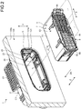
- FIG. 2 is a diagram illustrating an inner housing to be inserted into an outer housing
- FIG. 3 is an exploded perspective view of the connector according to the embodiment
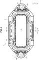
- FIG. 4 is a front view of the outer housing according to the embodiment
- FIG. 5 is a perspective view of the outer housing according to the embodiment
- FIG. 6 is a side view of the outer housing according to the embodiment
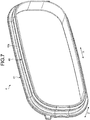
- FIG. 7 is a perspective view of a sealing member according to the embodiment
- FIG. 8 is a side view of the sealing member according to the embodiment
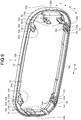
- FIG. 9 is a perspective view of a holder according to the embodiment
- FIG. 10 is a side view of the holder according to the embodiment.
- FIG. 11 is a perspective view of an outer shell part of the inner housing according to the embodiment
- FIG. 12 is a perspective view of a holding body of the inner housing according to the embodiment
- FIG. 13 is a plan view of the holding body according to the embodiment
- FIG. 14 is a side view of the holding body according to the embodiment
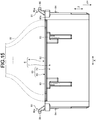
- FIG. 15 is a plan view of the inner housing according to the embodiment
- FIG. 16 is a perspective view illustrating the outer housing to be inserted into a hole part
- FIG. 17 is a perspective view illustrating fastening of bolts to a wall part
- FIG. 18 is a front view illustrating the outer housing fixed to the wall part
- FIG. 19 is a perspective view illustrating a counterpart connector to be connected to the connector according to the present embodiment.
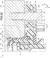
- FIG. 20 and FIG. 21 are a sectional view and a cross-sectional view of the outer housing fixed to the wall part, the sealing member, and the holder, and FIG. 22 is a sectional view of the outer housing and the holder.
- FIG. 20 illustrates an XX-XX section in FIG. 18 .
- FIG. 21 illustrates an XXI-XXI cross section in FIG. 18 .
- a connector 1 is fixed to a wall part 100.
- the wall part 100 is, for example, part of a housing of a device mounted on a vehicle.
- the wall part 100 may be a wall part constituting a housing of an inverter or a motor.
- the wall part 100 includes a first surface 100a and a second surface 100b.
- the first surface 100a is, for example, an outer surface of the housing.
- the second surface 100b is, for example, an inner surface of the housing.
- the wall part 100 includes a hole part 101.
- the hole part 101 passes through the wall part 100, and opens on each of the first surface 100a and the second surface 100b.
- the shape of the hole part 101 according to the present embodiment is a rectangle having four corners that are rounded in a circular arc shape.
- the connector 1 includes an outer housing 2, bolts 3, a sealing member 4, a holder 5, and an inner housing 6.
- the outer housing 2 includes a main body 20, a flange part 21, an inserting part 22, and a pair of opposed wall parts 23 and 23.
- the main body 20, the flange part 21, the inserting part 22, and the opposed wall parts 23 are integrally formed by an insulative synthetic resin, for example.
- the main body 20 has a tubular shape both ends of which are opened, and houses the inner housing 6.
- a sectional shape of the main body 20 is a rectangle having four corners that are rounded in a circular arc shape.
- a longitudinal direction on a section of the main body 20 is referred to as a "first direction X”, and a lateral direction on the section of the main body 20 is referred to as a "second direction Y".
- the first direction X and the second direction Y are orthogonal to each other.
- a direction along a center axis C1 of the main body 20 is referred to as an "axis direction Z”.
- the first direction X and the second direction Y are orthogonal to the axis direction Z.
- the inner housing 6 is inserted into the outer housing 2 along the axis direction Z.
- the first direction X and the second direction Y are orthogonal to an insertion direction Zin of the inner housing 6 with respect to the outer housing 2.
- the flange part 21 is connected to one end in the axis direction Z of the main body 20.
- the flange part 21 projects from an outer surface of the main body 20 in a direction orthogonal to the axis direction Z.
- the flange part 21 is formed in an annular shape to surround the outer surface of the main body 20.
- the inserting part 22 is a portion to be inserted into the hole part 101 of the wall part 100.
- the inserting part 22 projects from the flange part 21 toward an opposite side of the main body 20 side.
- the shape of the inserting part 22 is a tubular shape.
- a sectional shape of a section orthogonal to the axis direction Z of the exemplified inserting part 22 is a rectangle the four corners of which are rounded in a circular arc shape.
- An outer surface 22a of the inserting part 22 is a smooth surface.
- a pair of engaging parts 25 is disposed on an inner surface of the inserting part 22.
- the pair of engaging parts 25 is opposed to each other in the first direction X.
- the engaging parts 25 are engaged with the holder 5 to hold the holder 5.
- guides 27 for positioning the holder 5 are disposed on the inner surface of the inserting part 22.
- the guides 27 are disposed on a first inner surface 22c as a surface along the first direction X.
- Two guides 27 are disposed on the first inner surface 22c.
- the two guides 27 are disposed at both end parts in the first direction X of the first inner surface 22c.
- the guide 27 includes a pair of guide walls 26 and 26.
- the guide wall 26 includes a base 26a and an opposed part 26b.
- the base 26a projects from the first inner surface 22c toward the second direction Y.
- the opposed part 26b projects from a distal end of one base 26a toward the other base 26a along the first direction X. Distal ends of two opposed parts 26b are opposed to each other in the first direction X.
- the opposed part 26b is opposed to the first inner surface 22c in the second direction Y.
- the guide 27 guides a projecting part 53 (refer to FIG. 9 ) of the holder 5.
- the guide 27 regulates relative movement of the projecting part 53 with respect to the inserting part 22.
- the outer housing 2 includes a pair of fixing parts 21a.
- the fixing parts 21a are portions at both ends in the first direction X of the flange part 21. That is, the pair of fixing parts 21a is positioned on both sides in the first direction X across the inserting part 22.
- the fixing part 21a is a portion to be fixed to the first surface 100a of the wall part 100.
- a through hole 21b, into which the bolt 3 is inserted is disposed in the fixing part 21a.
- One through hole 21b is disposed in each of the fixing parts 21a.
- the through hole 21b passes through a collar 24.
- the collar 24 is a member having a cylindrical shape, and is made of metal, for example.
- the collar 24 is integrated with the flange part 21 by insert molding and the like. That is, the collar 24 constitutes the fixing part 21a together with surrounding resins.
- the through hole 21b passes through the collar 24 along the axis direction Z.
- a sectional shape of the through hole 21b is a circle.
- the two through holes 21b may be positioned on the same line in the first direction X.
- the through hole 21b of one of the fixing parts 21a and the through hole 21b of the other one of the fixing parts 21a may be positioned on a virtual line L1 along the first direction X.
- the pair of opposed wall parts 23 and 23 project from the flange part 21 along the axis direction Z.
- a projecting direction of the opposed wall part 23 with respect to the flange part 21 is the same as a projecting direction of the main body 20 with respect to the flange part 21.
- the pair of opposed wall parts 23 and 23 is opposed to each other in the second direction Y across the main body 20.
- a housing 201 of a counterpart connector 200 (refer to FIG. 19 ) is inserted between the opposed wall part 23 and the main body 20.
- the opposed wall part 23 includes a projection 23a having a round column shape. The projection 23a projects toward the main body 20 along the second direction Y.
- the sealing member 4 is mounted on the outer surface 22a of the inserting part 22 to seal between the inserting part 22 and the wall part 100.
- the sealing member 4 is formed by a resin having elasticity such as rubber. As illustrated in FIG. 7 , for example, the shape of the sealing member 4 is an annular shape.
- the sealing member 4 includes a first sealing part 40 and a second sealing part 41.
- the first sealing part 40 is a portion functioning as an axis seal.
- the second sealing part 41 is a portion functioning as a surface seal.
- the shape of the first sealing part 40 is a tubular shape having a center axis along the axis direction Z.
- the first sealing part 40 is mounted on the outer surface 22a of the inserting part 22. That is, the inserting part 22 is inserted into the first sealing part 40.
- a lip 40a is formed on an outer surface of the first sealing part 40. The lip 40a is disposed over the entire circumference of the outer surface of the first sealing part 40.
- the first sealing part 40 seals between the outer surface 22a of the inserting part 22 and a wall surface 101a of the hole part 101.
- the second sealing part 41 projects from the outer surface of the first sealing part 40 toward a direction orthogonal to the axis direction Z.
- the shape of the second sealing part 41 is an annular shape. That is, the second sealing part 41 is disposed over the entire circumference of the outer surface of the first sealing part 40.
- the second sealing part 41 seals between the flange part 21 of the outer housing 2 and the first surface 100a of the wall part 100.
- the holder 5 is a member that is fixed to a distal end part of the inserting part 22.
- the holder 5 has a function of holding the sealing member 4, a function of protecting the sealing member 4, and a function of suppressing eccentricity of the inserting part 22 with respect to the hole part 101.
- the holder 5 includes an abutting part 50, an annular part 51, engaging parts 52, and projecting parts 53.
- the abutting part 50, the annular part 51, the engaging parts 52, and the projecting parts 53 are integrally formed by an insulative synthetic resin, for example.
- the abutting part 50 is a portion that abuts on the wall surface 101a of the hole part 101 to regulate relative movement of the inserting part 22 with respect to the hole part 101.
- the exemplified abutting part 50 has a tubular shape, and is configured to cover the outer surface 22a of the inserting part 22.
- the shape of the abutting part 50 in a case of being viewed from the axis direction Z is a rectangle having four rounded corners.
- the abutting part 50 includes a first abutting surface 50a and a second abutting surface 50b.
- the first abutting surface 50a is a surface facing the first direction X in a state in which the holder 5 is fixed to the inserting part 22. Thus, the first abutting surface 50a is opposed to the wall surface 101a of the hole part 101 in the first direction X.
- the first abutting surface 50a is, for example, a plane.
- the second abutting surface 50b is a surface facing the second direction Y in a state in which the holder 5 is fixed to the inserting part 22. Thus, the second abutting surface 50b is opposed to the wall surface 101a of the hole part 101 in the second direction Y.
- the second abutting surface 50b is, for example, a curved surface that is slightly curved outward.
- the second abutting surface 50b may be substantially a flat surface.
- the abutting part 50 includes curved surfaces 50c that connect the first abutting surface 50a with the second abutting surface 50b.
- the curved surfaces 50c are disposed at four corner parts of the abutting part 50.
- the curved surface 50c is curved outward, and has a substantially circular ark shape, for example.
- the annular part 51 is a portion opposed to a distal end surface 22b of the inserting part 22.
- the shape of the annular part 51 in a case of being viewed from the axis direction Z is a rectangle having four rounded corners.
- the annular part 51 is formed to cover and hide the distal end surface 22b.
- the abutting part 50 projects from an opposed surface 51a of the annular part 51 along the axis direction Z.
- the opposed surface 51a is a surface of the annular part 51 on a side opposed to the distal end surface 22b.
- the abutting part 50 projects from an outer edge of the opposed surface 51a toward the axis direction Z.
- the engaging part 52 projects from the opposed surface 51a of the annular part 51 toward the axis direction Z.
- the engaging parts 52 are respectively disposed on two short side portions included in the annular part 51.
- the engaging part 52 includes a pair of flexible arms 52a.
- the pair of arms 52a are arranged side by side along the second direction Y.
- a pawl 52b is formed on a distal end part of the arm 52a. The pawl 52b is engaged with the engaging part 25 of the inserting part 22, and is locked by the engaging part 25.
- the projecting part 53 projects from the opposed surface 51a of the annular part 51 toward the axis direction Z.
- the projecting parts 53 are respectively disposed on two long side portions included in the annular part 51.
- a pair of the projecting parts 53 is disposed on one long side portion.
- the pair of the projecting parts 53 is disposed on both ends of the long side portion.
- the projecting part 53 includes a main part 53a and a projection 53b.
- the shape of the main part 53a is a rectangular flat plate shape.
- a principal plane of the main part 53a faces the second direction Y. That is, the main part 53a extends in a direction orthogonal to the second direction Y.
- the main part 53a includes a first surface 53c and a second surface 53d.
- the first surface 53c is a surface facing an inner side of the holder 5 of two principal planes included in the main part 53a.
- the second surface 53d is a surface facing an outer side of the holder 5.
- the projection 53b projects from the first surface 53c of the main part 53a.
- the projection 53b extends along the axis direction Z from a base end to a distal end of the main part 53a.
- Squeezing ribs 53e extending along the axis direction Z are disposed on the first surface 53c and the second surface 53d.
- the squeezing rib 53e can be plastically deformed when the projecting part 53 is inserted into the guide 27.
- the squeezing rib 53e suppress play between the projecting part 53 and the guide 27.
- the inner housing 6 includes an outer shell part 7 illustrated in FIG. 11 , and a holding body 8 illustrated in FIG. 12 to FIG. 14 .
- the outer shell part 7 includes an external wall part 70 having a tubular shape, and a partition wall 71.
- the external wall part 70 and the partition wall 71 are integrally formed by an insulative synthetic resin, for example.
- a sectional shape of the external wall part 70 on a section orthogonal to the axis direction Z is a rectangle having four rounded corners.
- the external wall part 70 includes a pair of first wall parts 70a and 70a, and a pair of second wall parts 70b and 70b.
- the pair of first wall parts 70a and 70a extends along the first direction X, and is opposed to each other in the second direction Y.
- the pair of second wall parts 70b and 70b extends along the second direction Y, and is opposed to each other in the first direction X.
- the partition wall 71 is orthogonal to the axis direction Z, and partitions a space part surrounded by the external wall part 70.
- the partition wall 71 is connected to the pair of first wall parts 70a and 70a and the pair of second wall parts 70b and 70b.
- the partition wall 71 includes a plurality of through holes 71a. A terminal of the connector 1 is inserted into the through hole 71a.
- the terminal held by the connector 1 is, for example, a male terminal.
- a slit 73 extending along the axis direction Z is formed in the first wall part 70a.
- the slit 73 extends from a rear end in the insertion direction Zin of the first wall part 70a toward the insertion direction Zin.
- Two slits 73 are disposed in one first wall part 70a.
- a notch 74 opening toward a rear side in the insertion direction Zin is formed on the second wall part 70b.
- Engaging parts 72 are disposed at a rear end in the insertion direction Zin of the external wall part 70.
- the engaging parts 72 are disposed at both ends in the first direction X of the external wall part 70.
- the engaging part 72 includes an arch part 72a and a projection 72b.
- the arch part 72a connects the pair of first wall parts 70a and 70a across the notch 74.
- the projection 72b projects from a center part of the arch part 72a toward the insertion direction Zin.
- the holding body 8 of the inner housing 6 includes a main body 80 and a projecting part 81.
- the main body 80 and the projecting part 81 are, for example, integrally formed by an insulative synthetic resin.
- the main body 80 is a portion to be engaged with the outer shell part 7.
- the shape of the exemplified main body 80 is a substantially rectangular parallelepiped shape.
- the main body 80 includes a plurality of cavities 80d.
- the cavity 80d passes through the main body 80 along the axis direction Z.
- the terminal of the connector 1 is inserted into the cavity 80d to be held by the cavity 80d.
- An outer wall surface of the main body 80 includes a pair of first wall surfaces 80a and 80a, and a pair of second wall surfaces 80b and 80b.
- the first wall surface 80a is a wall surface extending along the first direction X, and faces the second direction Y.
- the second wall surface 80b is a wall surface extending along the second direction Y, and faces the first direction X.
- a plate part 82 is disposed at a rear end in the insertion direction Zin of the main body 80.
- the plate part 82 projects from the first wall surface 80a toward the second direction Y.
- Ribs 83 are formed on the first wall surface 80a.
- the ribs 83 are connected to the plate part 82, and extend along the axis direction Z.
- the two ribs 83 are disposed on each first wall surface 80a.
- the rib 83 is inserted into the slit 73 of the outer shell part 7.
- a flexible arm 84 is disposed on each second wall surface 80b.
- the arm 84 is connected to a front side portion in the insertion direction Zin of the second wall surface 80b.
- the arm 84 extends along the axis direction Z toward a rear side in the insertion direction Zin.
- the arm 84 is engaged with the engaging part 25 (refer to FIG. 5 ) of the outer housing 2 when the inner housing 6 is inserted into the outer housing 2.
- the arm 84 is locked by the engaging part 25.
- the engaging part 25 regulates movement of the inner housing 6 in a direction of slipping out of the outer housing 2.
- the projecting part 81 projects from the main body 80 toward a rear side in the insertion direction Zin.
- One projecting part 81 is disposed for each of both ends in the first direction X of the main body 80.
- the projecting part 81 includes a pair of bases 85 and 85, and an operation part 86.
- the base 85 projects from a rear end 80c of the main body 80 toward a rear side in the insertion direction Zin.
- the base 85 is connected to the second wall surface 80b, and extends in a direction inclined with respect to the second wall surface 80b. That is, the base 85 is inclined to become more distant from the second wall surface 80b toward a rear side in the insertion direction Zin.
- the operation part 86 connects the pair of bases 85 and 85 along the second direction Y. Both ends of the operation part 86 in the second direction Y are connected to end parts of the bases 85.
- the shape of the operation part 86 is a flat plate shape or a rectangular column shape.
- the operation part 86 projects and extends from a rear end 85a in the insertion direction Zin of the base 85 toward the first direction X.
- An extending direction of the operation part 86 is a direction to be more distant from the main body 80 along the first direction X.
- the operation part 86 includes a rear end surface 86a facing a rear side in the insertion direction Zin, and a side surface 86b.
- the side surface 86b faces an opposite side of a center axis C2 side of the main body 80 in the first direction X.
- the operation part 86 is formed to be easily held by an operator.
- the operator holds a pair of the operation parts 86.
- the operator may sandwich the pair of operation parts 86 by one hand, or may hold the two operation parts 86 by different hands.
- the operator can push the rear end surface 86a.
- the rear end surface 86a is a plane, so that the operator can easily push the rear end surface 86a.
- the pair of the operation parts 86 is positioned on both ends in the longitudinal direction of the main body 80. Thus, the operator can uniformly apply pressing force to the inner housing 6 via two rear end surfaces 86a.
- FIG. 15 illustrates the inner housing 6 to which the outer shell part 7 and the holding body 8 are assembled.
- the external wall part 70 of the outer shell part 7 and the main body 80 of the holding body 8 constitute a main body 60 of the inner housing 6.
- An electric wire W connected to the terminal projects from the rear end 80c of the holding body 8 toward the outside.
- the operation part 86 projects from the main body 60 toward a rear side in the insertion direction Zin.
- the operation part 86 projects from the main body 60 along the first direction X.
- the operation part 86 hardly interferes with the electric wire W.
- the operator can easily assemble the inner housing 6 to the outer housing 2 while holding the operation parts 86.
- the outer housing 2 is attached to the wall part 100.
- the inserting part 22 of the outer housing 2 has the sealing member 4 and the holder 5 attached thereto.
- the operator inserts the inserting part 22 into the hole part 101.
- the operator inserts the inserting part 22 into the hole part 101 to reach a position where the fixing part 21a abuts on the first surface 100a, for example.
- the outer housing 2 is fixed to the wall part 100 by the bolts 3.
- the bolt 3 is inserted into the through hole 21b of the outer housing 2, and is screwed into a screw hole 102 of the wall part 100.
- the fixing parts 21a of the outer housing 2 are fastened to the wall part 100 by the two bolts 3.
- FIG. 2 the inner housing 6 is inserted into the outer housing 2.
- the inner housing 6 is inserted into the hole part 101 and the outer housing 2 from the second surface 100b side.
- the flexible arm 84 is engaged with the engaging part 25.
- FIG. 18 illustrates the connector 1 after the inner housing 6 is assembled to the outer housing 2.
- FIG. 19 illustrates the counterpart connector 200 corresponding to the connector 1 according to the present embodiment.
- the counterpart connector 200 is connected to the connector 1 that is fixed to the wall part 100.
- the counterpart connector 200 is what is called a lever-type connector, and includes the housing 201 and a lever 202.
- the lever 202 is coupled to the housing 201, and supported by the housing 201 in a rotatable manner.
- the lever 202 includes a guide groove 203.
- the projection 23a is inserted into the guide groove 203.
- the guide groove 203 draws the projection 23a to completely engage the housing 201 with the inner housing 6.
- the counterpart connector 200 can completely engage the housing 201 with the inner housing 6 with small force using the principle of the lever.
- FIG. 20 and FIG. 21 illustrate the inserting part 22 inserted into the hole part 101, the sealing member 4, and the holder 5.
- the inserting part 22, the sealing member 4, and the holder 5 are positioned concentrically with the hole part 101.
- a position concentric with the hole part 101 is simply referred to as a "concentric position”.
- the holder 5 is configured to have gaps G1 and G2 between itself and the wall surface 101a of the hole part 101 in a state in which the inserting part 22 is positioned concentrically with the hole part 101.
- the gap G1 is disposed between the first abutting surface 50a and the wall surface 101a of the hole part 101.
- the gap G2 is disposed between the second abutting surface 50b and the wall surface 101a of the hole part 101.
- a width Wd1 of the gap G1 and a width Wd2 of the gap G2 are defined to limit a relative movement range of the inserting part 22 with respect to the hole part 101.
- a gap G3 is present between the bolt 3 and a wall surface 21c of the through hole 21b.
- the bolt 3 is positioned concentrically with the through hole 21b.
- a width Wd3 of the gap G3 in the first direction X is, for example, defined to absorb tolerances of respective parts of the outer housing 2 and the like.
- a gap is present between the wall surface 21c and the bolt 3 also in the second direction Y.
- the gap between the wall surface 21c and the bolt 3 in the second direction Y is referred to as a "gap G4", and a width of the gap G4 is referred to as a "width Wd4".
- a value of the width Wd4 of the gap G4 in the second direction Y is, for example, the same as a value of the width Wd3.
- the gap G1 between the first abutting surface 50a and the wall surface 101a is narrower than the gap G3 between the wall surface 21c and the bolt 3. That is, a movable range of the inserting part 22 in the first direction X is narrowed.
- the movable range of the inserting part 22 in the first direction X is determined corresponding to the width Wd3 of the gap G3. That is, the inserting part 22 is allowed to move from the concentric position in a range of the width Wd3 along the first direction X.
- the connector 1 includes the holder 5 that regulates eccentricity of the inserting part 22.
- the first abutting surface 50a of the holder 5 abuts on the wall surface 101a of the hole part 101 so as to limit relative movement of the inserting part 22 with respect to the hole part 101.
- the movable range of the inserting part 22 in the first direction X is determined corresponding to the width Wd1 of the gap G1. In this case, the inserting part 22 is allowed to move from the concentric position in a range of the width Wd1. Thus, an amount of eccentricity of the inserting part 22 in the first direction X is reduced as compared with the case in which the holder 5 is not provided.
- the gap G2 between the second abutting surface 50b and the wall surface 101a is narrower than the gap G4 between the wall surface 21c and the bolt 3. That is, the movable range of the inserting part 22 in the second direction Y is narrowed.
- the movable range of the inserting part 22 in the second direction Y is determined corresponding to the width Wd4 of the gap G4. That is, the inserting part 22 is allowed to move from the concentric position in a range of the width Wd4 along the second direction Y.
- the second abutting surface 50b of the holder 5 abuts on the wall surface 101a of the hole part 101 so as to limit relative movement of the inserting part 22 with respect to the hole part 101.
- the movable range of the inserting part 22 in the second direction Y is determined corresponding to the width Wd2 of the gap G2. In this case, the inserting part 22 is allowed to move from the concentric position in a range of the width Wd2. Thus, an amount of eccentricity of the inserting part 22 in the second direction Y is reduced as compared with the case in which the holder 5 is not provided.
- eccentricity of the holder 5 with respect to the inserting part 22 is suppressed.
- the projecting part 53 of the holder 5 is inserted into the guide 27 of the outer housing 2.
- the main part 53a of the projecting part 53 is held between the first inner surface 22c and the opposed part 26b of the guide 27. That is, the guide 27 positions the holder 5 in the second direction Y, and regulates relative movement of the abutting part 50 with respect to the inserting part 22.
- the main part 53a of the projecting part 53 is held between the bases 26a of the guide 27.
- the guide 27 positions the holder 5 in the first direction X, and regulates relative movement of the abutting part 50 with respect to the inserting part 22. With this configuration, an amount of eccentricity of the inserting part 22 with respect to the hole part 101 is reduced.
- the connector 1 according to the present embodiment can suppress eccentricity of the inserting part 22 with respect to the hole part 101, and can suppress deterioration of waterproof performance of the sealing member 4.
- eccentricity of the inserting part 22 is suppressed, imbalance in a compression rate of the sealing member 4 is suppressed, and the sealing member 4 is compressed more uniformly. As a result, the waterproof performance of the sealing member 4 is improved.
- the holder 5 is configured to protect the sealing member 4 at the time when the outer housing 2 is inserted into the hole part 101.
- the abutting part 50 of the holder 5 is opposed to an end face 40b of the sealing member 4 in the axis direction Z.
- a thickness of the abutting part 50 is larger than a thickness of the end face 40b.
- the abutting part 50 protects the end face 40b of the sealing member 4 not to interfere with an edge of the hole part 101. Accordingly, the holder 5 can prevent deviation from being caused due to interference of the sealing member 4.
- the holder 5 also has a function of preventing the sealing member 4 from falling out of the outer housing 2.
- the connector 1 includes the bolt 3, the outer housing 2, the sealing member 4, and the holder 5.
- the outer housing 2 includes the fixing part 21a including the through hole 21b, and the inserting part 22 having a tubular shape.
- the fixing part 21a is a portion to be fixed to the wall part 100 by the bolt 3 that is inserted into the through hole 21b.
- the inserting part 22 is a portion projecting from the fixing part 21a to be inserted into the hole part 101 of the wall part 100.
- the sealing member 4 is mounted on the outer surface 22a of the inserting part 22 to seal between the inserting part 22 and the hole part 101.
- the holder 5 includes the abutting part 50, and is fixed to the distal end part of the inserting part 22.
- the abutting part 50 is a portion positioned between the outer surface 22a of the inserting part 22 and the hole part 101.
- the abutting part 50 abuts on the wall surface 101a of the hole part 101 so as to limit relative movement of the inserting part 22 with respect to the hole part 101.
- the gap between the wall surface 101a of the hole part 101 and the abutting part 50 is narrower than the gap between the wall surface 21c of the through hole 21b and the bolt 3.
- the gap G1 between the first abutting surface 50a of the abutting part 50 and the wall surface 101a of the hole part 101 is narrower than the gap G3 between the wall surface 21c of the through hole 21b and the bolt 3.
- the connector 1 according to the present embodiment can suppress eccentricity of the inserting part 22 with respect to the hole part 101, and can suppress deterioration of sealing performance of the sealing member 4.
- the abutting part 50 includes the first abutting surface 50a and the second abutting surface 50b.
- the first abutting surface 50a is a surface opposed to the wall surface 101a of the hole part 101 in the first direction X.
- the second abutting surface 50b is a surface opposed to the wall surface 101a of the hole part 101 in the second direction Y.
- the first direction X and the second direction Y are orthogonal to each other. In the first direction X, the gap G1 between the wall surface 101a of the hole part 101 and the first abutting surface 50a is narrower than the gap G3 between the wall surface 21c of the through hole 21b and the bolt 3.
- the gap G2 between the wall surface 101a of the hole part 101 and the second abutting surface 50b is narrower than the gap G4 between the wall surface 21c of the through hole 21b and the bolt 3.
- the abutting part 50 has a tubular shape, and covers the outer surface 22a of the inserting part 22.
- the shape of the abutting part 50 By causing the shape of the abutting part 50 to be the tubular shape, eccentricity of the inserting part 22 with respect to the hole part 101 is preferably suppressed. Additionally, by causing the abutting part 50 to have the tubular shape, the sealing member 4 can be protected by the abutting part 50.
- the abutting part 50 is opposed to the end face 40b of the sealing member 4 in the axis direction Z of the inserting part 22.
- the thickness of the abutting part 50 is larger than the thickness of the end face 40b of the sealing member 4. With this configuration, the end face 40b of the sealing member 4 can be protected by the abutting part 50.
- the holder 5 includes the annular part 51 having an annular shape, the engaging part 52, and the projecting part 53.
- the annular part 51 is a portion opposed to the distal end surface 22b of the inserting part 22.
- the engaging part 52 is a portion that is inserted into the inserting part 22 to be engaged with the inserting part 22.
- the projecting part 53 is a portion that projects from the annular part 51, and is positioned by the inserting part 22. As the projecting part 53 is positioned by the inserting part 22, eccentricity of the inserting part 22 with respect to the hole part 101 is hardly caused.
- the inserting part 22 includes the guide 27 that regulates relative movement of the projecting part 53 with respect to the inserting part 22 in the first direction X and the second direction Y. With this configuration, eccentricity of the inserting part 22 with respect to the hole part 101 is hardly caused.
- the shapes of the inserting part 22 and the holder 5, the position of the holder 5, and the like are not limited to the shapes and the positions exemplified in the embodiment.
- the shape of the abutting part 50 of the holder 5 is not limited to the tubular shape.
- the shape of the abutting part 50 may be any shape that can limit relative movement of the inserting part 22 with respect to the hole part 101 by abutting on the wall surface 101a.
- the number of the bolts 3 for fixing the outer housing 2 is not limited to two.
- the outer housing 2 may be fixed to the wall part 100 by three or more bolts 3.
- Pieces of content disclosed in the embodiment and the modification described above can be appropriately combined to be executed.
- the connector according to the present embodiment includes the housing including the inserting part having a tubular shape, the sealing member mounted on the outer surface of the inserting part, and the holder including the abutting part that is positioned between the outer surface of the inserting part and the hole part.
- the gap between the wall surface of the hole part and the abutting part is narrower than the gap between the wall surface of the through hole of the housing and the bolt.
- the abutting part can suppress eccentricity of the inserting part with respect to the hole part. Accordingly, the connector according to the present embodiment exhibits an effect of suppressing deterioration of sealing performance of the sealing member.
Landscapes
- Connector Housings Or Holding Contact Members (AREA)
Abstract
Description
- The present invention relates to a connector.
- In the related art, there is known a connector that is fixed to a hole part of a housing and the like. Japanese Patent Application Laid-open No.
2015-11946 - In the shield connector disclosed in Japanese Patent Application Laid-open No.
2015-11946 - In a connector including an inserting part to be inserted into a hole part, a sealing member may be provided for sealing between the inserting part and the hole part. In this case, it is preferable to suppress deterioration of sealing performance of the sealing member. For example, if eccentricity of the inserting part with respect to the hole part is suppressed, deterioration of sealing performance of the sealing member is suppressed.
- It is an object of the present invention to provide a connector that can suppress deterioration of sealing performance of the sealing member.
- A connector according to one aspect of the present invention includes a bolt; a housing including a fixing part having a through hole into which the bolt is inserted, the fixing part being fixed to a wall part by the bolt, and an inserting part having a tubular shape that projects from the fixing part to be inserted into a hole part of the wall part; a sealing member that is mounted on an outer surface of the inserting part to seal between the inserting part and the hole part; and a holder including an abutting part that is positioned between an outer surface of the inserting part and the hole part, the holder being fixed to a distal end part of the inserting part, wherein the abutting part abuts on a wall surface of the hole part so as to limit relative movement of the inserting part with respect to the hole part, and a gap between the wall surface of the hole part and the abutting part is narrower than a gap between a wall surface of the through hole and the bolt.
- The above and other objects, features, advantages and technical and industrial significance of this invention will be better understood by reading the following detailed description of presently preferred embodiments of the invention, when considered in connection with the accompanying drawings.
-
-
FIG. 1 is a perspective view illustrating a connector according to an embodiment; -
FIG. 2 is a diagram illustrating an inner housing to be inserted into an outer housing; -
FIG. 3 is an exploded perspective view of the connector according to the embodiment; -
FIG. 4 is a front view of the outer housing according to the embodiment; -
FIG. 5 is a perspective view of the outer housing according to the embodiment; -
FIG. 6 is a side view of the outer housing according to the embodiment; -
FIG. 7 is a perspective view of a sealing member according to the embodiment; -
FIG. 8 is a side view of the sealing member according to the embodiment; -
FIG. 9 is a perspective view of a holder according to the embodiment; -
FIG. 10 is a side view of the holder according to the embodiment; -
FIG. 11 is a perspective view of an outer shell part of the inner housing according to the embodiment; -
FIG. 12 is a perspective view of a holding body of the inner housing according to the embodiment; -
FIG. 13 is a plan view of the holding body according to the embodiment; -
FIG. 14 is a side view of the holding body according to the embodiment; -
FIG. 15 is a plan view of the inner housing according to the embodiment; -
FIG. 16 is a perspective view illustrating the outer housing to be inserted into a hole part; -
FIG. 17 is a perspective view illustrating fastening of bolts to a wall part; -
FIG. 18 is a front view illustrating the outer housing fixed to the wall part; -
FIG. 19 is a perspective view illustrating a counterpart connector to be connected to the connector according to the present embodiment; -
FIG. 20 is a sectional view of the outer housing fixed to the wall part, the sealing member, and the holder; -
FIG. 21 is a cross-sectional view of the outer housing fixed to the wall part, the sealing member, and the holder; and -
FIG. 22 is a sectional view of the outer housing and the holder. - The following describes a connector according to an embodiment of the present invention in detail with reference to the drawings. The present invention is not limited to the embodiment. Constituent elements in the embodiment described below include a constituent element that is easily conceivable by those skilled in the art, or substantially the same constituent element.
- The following describes the embodiment with reference to
FIG. 1 to FIG. 22 . The present embodiment relates to a connector.FIG. 1 is a perspective view illustrating the connector according to the embodiment,FIG. 2 is a diagram illustrating an inner housing to be inserted into an outer housing,FIG. 3 is an exploded perspective view of the connector according to the embodiment,FIG. 4 is a front view of the outer housing according to the embodiment,FIG. 5 is a perspective view of the outer housing according to the embodiment,FIG. 6 is a side view of the outer housing according to the embodiment,FIG. 7 is a perspective view of a sealing member according to the embodiment,FIG. 8 is a side view of the sealing member according to the embodiment,FIG. 9 is a perspective view of a holder according to the embodiment, andFIG. 10 is a side view of the holder according to the embodiment. -
FIG. 11 is a perspective view of an outer shell part of the inner housing according to the embodiment,FIG. 12 is a perspective view of a holding body of the inner housing according to the embodiment,FIG. 13 is a plan view of the holding body according to the embodiment,FIG. 14 is a side view of the holding body according to the embodiment,FIG. 15 is a plan view of the inner housing according to the embodiment,FIG. 16 is a perspective view illustrating the outer housing to be inserted into a hole part,FIG. 17 is a perspective view illustrating fastening of bolts to a wall part,FIG. 18 is a front view illustrating the outer housing fixed to the wall part, andFIG. 19 is a perspective view illustrating a counterpart connector to be connected to the connector according to the present embodiment. -
FIG. 20 andFIG. 21 are a sectional view and a cross-sectional view of the outer housing fixed to the wall part, the sealing member, and the holder, andFIG. 22 is a sectional view of the outer housing and the holder.FIG. 20 illustrates an XX-XX section inFIG. 18 .FIG. 21 illustrates an XXI-XXI cross section inFIG. 18 . - As illustrated in
FIG. 1 andFIG. 2 , aconnector 1 according to the present embodiment is fixed to awall part 100. Thewall part 100 is, for example, part of a housing of a device mounted on a vehicle. Thewall part 100 may be a wall part constituting a housing of an inverter or a motor. Thewall part 100 includes afirst surface 100a and asecond surface 100b. Thefirst surface 100a is, for example, an outer surface of the housing. Thesecond surface 100b is, for example, an inner surface of the housing. As illustrated inFIG. 2 , thewall part 100 includes ahole part 101. Thehole part 101 passes through thewall part 100, and opens on each of thefirst surface 100a and thesecond surface 100b. The shape of thehole part 101 according to the present embodiment is a rectangle having four corners that are rounded in a circular arc shape. - As illustrated in
FIG. 3 , theconnector 1 includes anouter housing 2,bolts 3, a sealingmember 4, aholder 5, and aninner housing 6. Theouter housing 2 includes amain body 20, aflange part 21, aninserting part 22, and a pair ofopposed wall parts main body 20, theflange part 21, theinserting part 22, and theopposed wall parts 23 are integrally formed by an insulative synthetic resin, for example. Themain body 20 has a tubular shape both ends of which are opened, and houses theinner housing 6. A sectional shape of themain body 20 is a rectangle having four corners that are rounded in a circular arc shape. - In the following description, a longitudinal direction on a section of the
main body 20 is referred to as a "first direction X", and a lateral direction on the section of themain body 20 is referred to as a "second direction Y". The first direction X and the second direction Y are orthogonal to each other. A direction along a center axis C1 of themain body 20 is referred to as an "axis direction Z". The first direction X and the second direction Y are orthogonal to the axis direction Z. Theinner housing 6 is inserted into theouter housing 2 along the axis direction Z. Thus, the first direction X and the second direction Y are orthogonal to an insertion direction Zin of theinner housing 6 with respect to theouter housing 2. - The
flange part 21 is connected to one end in the axis direction Z of themain body 20. Theflange part 21 projects from an outer surface of themain body 20 in a direction orthogonal to the axis direction Z. Theflange part 21 is formed in an annular shape to surround the outer surface of themain body 20. - The inserting
part 22 is a portion to be inserted into thehole part 101 of thewall part 100. The insertingpart 22 projects from theflange part 21 toward an opposite side of themain body 20 side. The shape of the insertingpart 22 is a tubular shape. A sectional shape of a section orthogonal to the axis direction Z of the exemplified insertingpart 22 is a rectangle the four corners of which are rounded in a circular arc shape. Anouter surface 22a of the insertingpart 22 is a smooth surface. A pair of engagingparts 25 is disposed on an inner surface of the insertingpart 22. The pair of engagingparts 25 is opposed to each other in the first direction X. The engagingparts 25 are engaged with theholder 5 to hold theholder 5. - As illustrated in
FIG. 5 , guides 27 for positioning theholder 5 are disposed on the inner surface of the insertingpart 22. Theguides 27 are disposed on a firstinner surface 22c as a surface along the first direction X. Two guides 27 are disposed on the firstinner surface 22c. The two guides 27 are disposed at both end parts in the first direction X of the firstinner surface 22c. - The
guide 27 includes a pair ofguide walls guide wall 26 includes abase 26a and anopposed part 26b. Thebase 26a projects from the firstinner surface 22c toward the second direction Y. Theopposed part 26b projects from a distal end of onebase 26a toward theother base 26a along the first direction X. Distal ends of twoopposed parts 26b are opposed to each other in the first direction X. Theopposed part 26b is opposed to the firstinner surface 22c in the second direction Y. Theguide 27 guides a projecting part 53 (refer toFIG. 9 ) of theholder 5. Theguide 27 regulates relative movement of the projectingpart 53 with respect to the insertingpart 22. - The
outer housing 2 includes a pair of fixingparts 21a. The fixingparts 21a are portions at both ends in the first direction X of theflange part 21. That is, the pair of fixingparts 21a is positioned on both sides in the first direction X across the insertingpart 22. The fixingpart 21a is a portion to be fixed to thefirst surface 100a of thewall part 100. A throughhole 21b, into which thebolt 3 is inserted is disposed in the fixingpart 21a. One throughhole 21b is disposed in each of the fixingparts 21a. - The through
hole 21b according to the present embodiment passes through acollar 24. Thecollar 24 is a member having a cylindrical shape, and is made of metal, for example. Thecollar 24 is integrated with theflange part 21 by insert molding and the like. That is, thecollar 24 constitutes the fixingpart 21a together with surrounding resins. The throughhole 21b passes through thecollar 24 along the axis direction Z. A sectional shape of the throughhole 21b is a circle. - The two through
holes 21b may be positioned on the same line in the first direction X. For example, the throughhole 21b of one of the fixingparts 21a and the throughhole 21b of the other one of the fixingparts 21a may be positioned on a virtual line L1 along the first direction X. - The pair of opposed
wall parts flange part 21 along the axis direction Z. A projecting direction of theopposed wall part 23 with respect to theflange part 21 is the same as a projecting direction of themain body 20 with respect to theflange part 21. The pair of opposedwall parts main body 20. Ahousing 201 of a counterpart connector 200 (refer toFIG. 19 ) is inserted between theopposed wall part 23 and themain body 20. Theopposed wall part 23 includes aprojection 23a having a round column shape. Theprojection 23a projects toward themain body 20 along the second direction Y. - The sealing
member 4 is mounted on theouter surface 22a of the insertingpart 22 to seal between the insertingpart 22 and thewall part 100. The sealingmember 4 is formed by a resin having elasticity such as rubber. As illustrated inFIG. 7 , for example, the shape of the sealingmember 4 is an annular shape. The sealingmember 4 includes a first sealingpart 40 and asecond sealing part 41. Thefirst sealing part 40 is a portion functioning as an axis seal. Thesecond sealing part 41 is a portion functioning as a surface seal. - The shape of the first sealing
part 40 is a tubular shape having a center axis along the axis direction Z. Thefirst sealing part 40 is mounted on theouter surface 22a of the insertingpart 22. That is, the insertingpart 22 is inserted into the first sealingpart 40. Alip 40a is formed on an outer surface of the first sealingpart 40. Thelip 40a is disposed over the entire circumference of the outer surface of the first sealingpart 40. Thefirst sealing part 40 seals between theouter surface 22a of the insertingpart 22 and awall surface 101a of thehole part 101. - The
second sealing part 41 projects from the outer surface of the first sealingpart 40 toward a direction orthogonal to the axis direction Z. The shape of the second sealingpart 41 is an annular shape. That is, the second sealingpart 41 is disposed over the entire circumference of the outer surface of the first sealingpart 40. Thesecond sealing part 41 seals between theflange part 21 of theouter housing 2 and thefirst surface 100a of thewall part 100. - The
holder 5 is a member that is fixed to a distal end part of the insertingpart 22. Theholder 5 has a function of holding the sealingmember 4, a function of protecting the sealingmember 4, and a function of suppressing eccentricity of the insertingpart 22 with respect to thehole part 101. As illustrated inFIG. 9 andFIG. 10 , theholder 5 includes anabutting part 50, anannular part 51, engagingparts 52, and projectingparts 53. The abuttingpart 50, theannular part 51, the engagingparts 52, and the projectingparts 53 are integrally formed by an insulative synthetic resin, for example. - The abutting
part 50 is a portion that abuts on thewall surface 101a of thehole part 101 to regulate relative movement of the insertingpart 22 with respect to thehole part 101. The exemplified abuttingpart 50 has a tubular shape, and is configured to cover theouter surface 22a of the insertingpart 22. The shape of theabutting part 50 in a case of being viewed from the axis direction Z is a rectangle having four rounded corners. The abuttingpart 50 includes a firstabutting surface 50a and a secondabutting surface 50b. - The first
abutting surface 50a is a surface facing the first direction X in a state in which theholder 5 is fixed to the insertingpart 22. Thus, the firstabutting surface 50a is opposed to thewall surface 101a of thehole part 101 in the first direction X. The firstabutting surface 50a is, for example, a plane. - The second
abutting surface 50b is a surface facing the second direction Y in a state in which theholder 5 is fixed to the insertingpart 22. Thus, the secondabutting surface 50b is opposed to thewall surface 101a of thehole part 101 in the second direction Y. The secondabutting surface 50b is, for example, a curved surface that is slightly curved outward. The secondabutting surface 50b may be substantially a flat surface. - The abutting
part 50 includescurved surfaces 50c that connect the firstabutting surface 50a with the secondabutting surface 50b. Thecurved surfaces 50c are disposed at four corner parts of theabutting part 50. Thecurved surface 50c is curved outward, and has a substantially circular ark shape, for example. - The
annular part 51 is a portion opposed to adistal end surface 22b of the insertingpart 22. The shape of theannular part 51 in a case of being viewed from the axis direction Z is a rectangle having four rounded corners. Theannular part 51 is formed to cover and hide thedistal end surface 22b. The abuttingpart 50 projects from anopposed surface 51a of theannular part 51 along the axis direction Z. Theopposed surface 51a is a surface of theannular part 51 on a side opposed to thedistal end surface 22b. The abuttingpart 50 projects from an outer edge of theopposed surface 51a toward the axis direction Z. - The engaging
part 52 projects from theopposed surface 51a of theannular part 51 toward the axis direction Z. The engagingparts 52 are respectively disposed on two short side portions included in theannular part 51. The engagingpart 52 includes a pair offlexible arms 52a. The pair ofarms 52a are arranged side by side along the second direction Y. Apawl 52b is formed on a distal end part of thearm 52a. Thepawl 52b is engaged with the engagingpart 25 of the insertingpart 22, and is locked by the engagingpart 25. - The projecting
part 53 projects from theopposed surface 51a of theannular part 51 toward the axis direction Z. The projectingparts 53 are respectively disposed on two long side portions included in theannular part 51. A pair of the projectingparts 53 is disposed on one long side portion. The pair of the projectingparts 53 is disposed on both ends of the long side portion. The projectingpart 53 includes amain part 53a and aprojection 53b. The shape of themain part 53a is a rectangular flat plate shape. A principal plane of themain part 53a faces the second direction Y. That is, themain part 53a extends in a direction orthogonal to the second direction Y. - The
main part 53a includes afirst surface 53c and asecond surface 53d. Thefirst surface 53c is a surface facing an inner side of theholder 5 of two principal planes included in themain part 53a. Thesecond surface 53d is a surface facing an outer side of theholder 5. Theprojection 53b projects from thefirst surface 53c of themain part 53a. Theprojection 53b extends along the axis direction Z from a base end to a distal end of themain part 53a. Squeezingribs 53e extending along the axis direction Z are disposed on thefirst surface 53c and thesecond surface 53d. The squeezingrib 53e can be plastically deformed when the projectingpart 53 is inserted into theguide 27. The squeezingrib 53e suppress play between the projectingpart 53 and theguide 27. - The
inner housing 6 according to the present embodiment includes anouter shell part 7 illustrated inFIG. 11 , and a holdingbody 8 illustrated inFIG. 12 to FIG. 14 . As illustrated inFIG. 11 , theouter shell part 7 includes anexternal wall part 70 having a tubular shape, and apartition wall 71. Theexternal wall part 70 and thepartition wall 71 are integrally formed by an insulative synthetic resin, for example. A sectional shape of theexternal wall part 70 on a section orthogonal to the axis direction Z is a rectangle having four rounded corners. Theexternal wall part 70 includes a pair offirst wall parts second wall parts first wall parts second wall parts - The
partition wall 71 is orthogonal to the axis direction Z, and partitions a space part surrounded by theexternal wall part 70. Thepartition wall 71 is connected to the pair offirst wall parts second wall parts partition wall 71 includes a plurality of throughholes 71a. A terminal of theconnector 1 is inserted into the throughhole 71a. The terminal held by theconnector 1 is, for example, a male terminal. - A slit 73 extending along the axis direction Z is formed in the
first wall part 70a. Theslit 73 extends from a rear end in the insertion direction Zin of thefirst wall part 70a toward the insertion direction Zin. Twoslits 73 are disposed in onefirst wall part 70a. Anotch 74 opening toward a rear side in the insertion direction Zin is formed on thesecond wall part 70b. - Engaging
parts 72 are disposed at a rear end in the insertion direction Zin of theexternal wall part 70. The engagingparts 72 are disposed at both ends in the first direction X of theexternal wall part 70. The engagingpart 72 includes anarch part 72a and aprojection 72b. Thearch part 72a connects the pair offirst wall parts notch 74. Theprojection 72b projects from a center part of thearch part 72a toward the insertion direction Zin. - As illustrated in
FIG. 12 , the holdingbody 8 of theinner housing 6 includes amain body 80 and a projectingpart 81. Themain body 80 and the projectingpart 81 are, for example, integrally formed by an insulative synthetic resin. Themain body 80 is a portion to be engaged with theouter shell part 7. The shape of the exemplifiedmain body 80 is a substantially rectangular parallelepiped shape. Themain body 80 includes a plurality ofcavities 80d. Thecavity 80d passes through themain body 80 along the axis direction Z. The terminal of theconnector 1 is inserted into thecavity 80d to be held by thecavity 80d. - An outer wall surface of the
main body 80 includes a pair of first wall surfaces 80a and 80a, and a pair of second wall surfaces 80b and 80b. Thefirst wall surface 80a is a wall surface extending along the first direction X, and faces the second direction Y. Thesecond wall surface 80b is a wall surface extending along the second direction Y, and faces the first direction X. Aplate part 82 is disposed at a rear end in the insertion direction Zin of themain body 80. Theplate part 82 projects from thefirst wall surface 80a toward the second direction Y.Ribs 83 are formed on thefirst wall surface 80a. Theribs 83 are connected to theplate part 82, and extend along the axis direction Z. The tworibs 83 are disposed on eachfirst wall surface 80a. Therib 83 is inserted into theslit 73 of theouter shell part 7. - A
flexible arm 84 is disposed on eachsecond wall surface 80b. Thearm 84 is connected to a front side portion in the insertion direction Zin of thesecond wall surface 80b. Thearm 84 extends along the axis direction Z toward a rear side in the insertion direction Zin. Thearm 84 is engaged with the engaging part 25 (refer toFIG. 5 ) of theouter housing 2 when theinner housing 6 is inserted into theouter housing 2. When theinner housing 6 and theouter housing 2 are completely engaged with each other, thearm 84 is locked by the engagingpart 25. The engagingpart 25 regulates movement of theinner housing 6 in a direction of slipping out of theouter housing 2. - The projecting
part 81 projects from themain body 80 toward a rear side in the insertion direction Zin. One projectingpart 81 is disposed for each of both ends in the first direction X of themain body 80. The projectingpart 81 includes a pair ofbases operation part 86. The base 85 projects from arear end 80c of themain body 80 toward a rear side in the insertion direction Zin. Thebase 85 is connected to thesecond wall surface 80b, and extends in a direction inclined with respect to thesecond wall surface 80b. That is, thebase 85 is inclined to become more distant from thesecond wall surface 80b toward a rear side in the insertion direction Zin. - The
operation part 86 connects the pair ofbases operation part 86 in the second direction Y are connected to end parts of thebases 85. The shape of theoperation part 86 is a flat plate shape or a rectangular column shape. Theoperation part 86 projects and extends from arear end 85a in the insertion direction Zin of the base 85 toward the first direction X. An extending direction of theoperation part 86 is a direction to be more distant from themain body 80 along the first direction X. As illustrated inFIG. 13 , for example, theoperation part 86 includes arear end surface 86a facing a rear side in the insertion direction Zin, and aside surface 86b. Theside surface 86b faces an opposite side of a center axis C2 side of themain body 80 in the first direction X. - The
operation part 86 is formed to be easily held by an operator. For example, at the time of assembling theinner housing 6 to theouter housing 2, the operator holds a pair of theoperation parts 86. The operator may sandwich the pair ofoperation parts 86 by one hand, or may hold the twooperation parts 86 by different hands. Additionally, at the time of inserting theinner housing 6 into theouter housing 2, the operator can push therear end surface 86a. Therear end surface 86a is a plane, so that the operator can easily push therear end surface 86a. The pair of theoperation parts 86 is positioned on both ends in the longitudinal direction of themain body 80. Thus, the operator can uniformly apply pressing force to theinner housing 6 via tworear end surfaces 86a. -
FIG. 15 illustrates theinner housing 6 to which theouter shell part 7 and the holdingbody 8 are assembled. Theexternal wall part 70 of theouter shell part 7 and themain body 80 of the holdingbody 8 constitute amain body 60 of theinner housing 6. An electric wire W connected to the terminal projects from therear end 80c of the holdingbody 8 toward the outside. Theoperation part 86 projects from themain body 60 toward a rear side in the insertion direction Zin. Theoperation part 86 projects from themain body 60 along the first direction X. Thus, theoperation part 86 hardly interferes with the electric wire W. The operator can easily assemble theinner housing 6 to theouter housing 2 while holding theoperation parts 86. - The following describes an assembling method for the
connector 1 according to the present embodiment. First, as illustrated inFIG. 16 , theouter housing 2 is attached to thewall part 100. The insertingpart 22 of theouter housing 2 has the sealingmember 4 and theholder 5 attached thereto. The operator inserts the insertingpart 22 into thehole part 101. The operator inserts the insertingpart 22 into thehole part 101 to reach a position where the fixingpart 21a abuts on thefirst surface 100a, for example. - Next, as illustrated in
FIG. 17 , theouter housing 2 is fixed to thewall part 100 by thebolts 3. Thebolt 3 is inserted into the throughhole 21b of theouter housing 2, and is screwed into ascrew hole 102 of thewall part 100. The fixingparts 21a of theouter housing 2 are fastened to thewall part 100 by the twobolts 3. - Next, as illustrated in
FIG. 2 , theinner housing 6 is inserted into theouter housing 2. Theinner housing 6 is inserted into thehole part 101 and theouter housing 2 from thesecond surface 100b side. When theinner housing 6 is inserted into theouter housing 2 to reach a completely engaged position, theflexible arm 84 is engaged with the engagingpart 25. When theinner housing 6 is completely engaged with theouter housing 2, assembly of theconnector 1 according to the embodiment is completed.FIG. 18 illustrates theconnector 1 after theinner housing 6 is assembled to theouter housing 2. -
FIG. 19 illustrates thecounterpart connector 200 corresponding to theconnector 1 according to the present embodiment. As illustrated inFIG. 19 , thecounterpart connector 200 is connected to theconnector 1 that is fixed to thewall part 100. Thecounterpart connector 200 is what is called a lever-type connector, and includes thehousing 201 and alever 202. Thelever 202 is coupled to thehousing 201, and supported by thehousing 201 in a rotatable manner. Thelever 202 includes aguide groove 203. - When the
housing 201 is engaged with theinner housing 6, theprojection 23a is inserted into theguide groove 203. When thelever 202 is rotated thereafter, theguide groove 203 draws theprojection 23a to completely engage thehousing 201 with theinner housing 6. Thecounterpart connector 200 can completely engage thehousing 201 with theinner housing 6 with small force using the principle of the lever. - As described below, the
connector 1 according to the present embodiment is configured to be able to suppress eccentricity of the insertingpart 22 with respect to thehole part 101.FIG. 20 andFIG. 21 illustrate the insertingpart 22 inserted into thehole part 101, the sealingmember 4, and theholder 5. InFIG. 20 andFIG. 21 , the insertingpart 22, the sealingmember 4, and theholder 5 are positioned concentrically with thehole part 101. In the following description about the insertingpart 22, a position concentric with thehole part 101 is simply referred to as a "concentric position". - The
holder 5 according to the present embodiment is configured to have gaps G1 and G2 between itself and thewall surface 101a of thehole part 101 in a state in which the insertingpart 22 is positioned concentrically with thehole part 101. As illustrated inFIG. 20 , the gap G1 is disposed between the firstabutting surface 50a and thewall surface 101a of thehole part 101. As illustrated inFIG. 21 , the gap G2 is disposed between the secondabutting surface 50b and thewall surface 101a of thehole part 101. As described below, a width Wd1 of the gap G1 and a width Wd2 of the gap G2 are defined to limit a relative movement range of the insertingpart 22 with respect to thehole part 101. - As illustrated in
FIG. 20 , a gap G3 is present between thebolt 3 and awall surface 21c of the throughhole 21b. InFIG. 20 , thebolt 3 is positioned concentrically with the throughhole 21b. A width Wd3 of the gap G3 in the first direction X is, for example, defined to absorb tolerances of respective parts of theouter housing 2 and the like. Although not illustrated, a gap is present between thewall surface 21c and thebolt 3 also in the second direction Y. The gap between thewall surface 21c and thebolt 3 in the second direction Y is referred to as a "gap G4", and a width of the gap G4 is referred to as a "width Wd4". A value of the width Wd4 of the gap G4 in the second direction Y is, for example, the same as a value of the width Wd3. - In the present embodiment, the gap G1 between the first
abutting surface 50a and thewall surface 101a is narrower than the gap G3 between thewall surface 21c and thebolt 3. That is, a movable range of the insertingpart 22 in the first direction X is narrowed. In a case in which theholder 5 is not provided, the movable range of the insertingpart 22 in the first direction X is determined corresponding to the width Wd3 of the gap G3. That is, the insertingpart 22 is allowed to move from the concentric position in a range of the width Wd3 along the first direction X. - On the other hand, the
connector 1 according to the present embodiment includes theholder 5 that regulates eccentricity of the insertingpart 22. The firstabutting surface 50a of theholder 5 abuts on thewall surface 101a of thehole part 101 so as to limit relative movement of the insertingpart 22 with respect to thehole part 101. The movable range of the insertingpart 22 in the first direction X is determined corresponding to the width Wd1 of the gap G1. In this case, the insertingpart 22 is allowed to move from the concentric position in a range of the width Wd1. Thus, an amount of eccentricity of the insertingpart 22 in the first direction X is reduced as compared with the case in which theholder 5 is not provided. - The gap G2 between the second
abutting surface 50b and thewall surface 101a is narrower than the gap G4 between thewall surface 21c and thebolt 3. That is, the movable range of the insertingpart 22 in the second direction Y is narrowed. In a case in which theholder 5 is not provided, the movable range of the insertingpart 22 in the second direction Y is determined corresponding to the width Wd4 of the gap G4. That is, the insertingpart 22 is allowed to move from the concentric position in a range of the width Wd4 along the second direction Y. - On the other hand, the second
abutting surface 50b of theholder 5 abuts on thewall surface 101a of thehole part 101 so as to limit relative movement of the insertingpart 22 with respect to thehole part 101. The movable range of the insertingpart 22 in the second direction Y is determined corresponding to the width Wd2 of the gap G2. In this case, the insertingpart 22 is allowed to move from the concentric position in a range of the width Wd2. Thus, an amount of eccentricity of the insertingpart 22 in the second direction Y is reduced as compared with the case in which theholder 5 is not provided. - In the
connector 1 according to the present embodiment, as illustrated inFIG. 22 , eccentricity of theholder 5 with respect to the insertingpart 22 is suppressed. As illustrated inFIG. 22 , the projectingpart 53 of theholder 5 is inserted into theguide 27 of theouter housing 2. Themain part 53a of the projectingpart 53 is held between the firstinner surface 22c and theopposed part 26b of theguide 27. That is, theguide 27 positions theholder 5 in the second direction Y, and regulates relative movement of theabutting part 50 with respect to the insertingpart 22. Themain part 53a of the projectingpart 53 is held between thebases 26a of theguide 27. That is, theguide 27 positions theholder 5 in the first direction X, and regulates relative movement of theabutting part 50 with respect to the insertingpart 22. With this configuration, an amount of eccentricity of the insertingpart 22 with respect to thehole part 101 is reduced. - The
connector 1 according to the present embodiment can suppress eccentricity of the insertingpart 22 with respect to thehole part 101, and can suppress deterioration of waterproof performance of the sealingmember 4. As the eccentricity of the insertingpart 22 is suppressed, imbalance in a compression rate of the sealingmember 4 is suppressed, and the sealingmember 4 is compressed more uniformly. As a result, the waterproof performance of the sealingmember 4 is improved. - The
holder 5 according to the present embodiment is configured to protect the sealingmember 4 at the time when theouter housing 2 is inserted into thehole part 101. As illustrated inFIG. 20 , for example, the abuttingpart 50 of theholder 5 is opposed to anend face 40b of the sealingmember 4 in the axis direction Z. A thickness of theabutting part 50 is larger than a thickness of theend face 40b. Thus, at the time when the insertingpart 22 is inserted into thehole part 101, the abuttingpart 50 protects theend face 40b of the sealingmember 4 not to interfere with an edge of thehole part 101. Accordingly, theholder 5 can prevent deviation from being caused due to interference of the sealingmember 4. Theholder 5 also has a function of preventing the sealingmember 4 from falling out of theouter housing 2. - As described above, the
connector 1 according to the embodiment includes thebolt 3, theouter housing 2, the sealingmember 4, and theholder 5. Theouter housing 2 includes the fixingpart 21a including the throughhole 21b, and the insertingpart 22 having a tubular shape. The fixingpart 21a is a portion to be fixed to thewall part 100 by thebolt 3 that is inserted into the throughhole 21b. The insertingpart 22 is a portion projecting from the fixingpart 21a to be inserted into thehole part 101 of thewall part 100. The sealingmember 4 is mounted on theouter surface 22a of the insertingpart 22 to seal between the insertingpart 22 and thehole part 101. - The
holder 5 includes theabutting part 50, and is fixed to the distal end part of the insertingpart 22. The abuttingpart 50 is a portion positioned between theouter surface 22a of the insertingpart 22 and thehole part 101. The abuttingpart 50 abuts on thewall surface 101a of thehole part 101 so as to limit relative movement of the insertingpart 22 with respect to thehole part 101. The gap between thewall surface 101a of thehole part 101 and theabutting part 50 is narrower than the gap between thewall surface 21c of the throughhole 21b and thebolt 3. For example, the gap G1 between the firstabutting surface 50a of theabutting part 50 and thewall surface 101a of thehole part 101 is narrower than the gap G3 between thewall surface 21c of the throughhole 21b and thebolt 3. Theconnector 1 according to the present embodiment can suppress eccentricity of the insertingpart 22 with respect to thehole part 101, and can suppress deterioration of sealing performance of the sealingmember 4. - The abutting
part 50 according to the present embodiment includes the firstabutting surface 50a and the secondabutting surface 50b. The firstabutting surface 50a is a surface opposed to thewall surface 101a of thehole part 101 in the first direction X. The secondabutting surface 50b is a surface opposed to thewall surface 101a of thehole part 101 in the second direction Y. The first direction X and the second direction Y are orthogonal to each other. In the first direction X, the gap G1 between thewall surface 101a of thehole part 101 and the firstabutting surface 50a is narrower than the gap G3 between thewall surface 21c of the throughhole 21b and thebolt 3. In the second direction Y, the gap G2 between thewall surface 101a of thehole part 101 and the secondabutting surface 50b is narrower than the gap G4 between thewall surface 21c of the throughhole 21b and thebolt 3. With this configuration, eccentricity of the insertingpart 22 with respect to thehole part 101 is suppressed in two directions, that is, the first direction X and the second direction Y. - The abutting
part 50 according to the present embodiment has a tubular shape, and covers theouter surface 22a of the insertingpart 22. By causing the shape of theabutting part 50 to be the tubular shape, eccentricity of the insertingpart 22 with respect to thehole part 101 is preferably suppressed. Additionally, by causing the abuttingpart 50 to have the tubular shape, the sealingmember 4 can be protected by the abuttingpart 50. - The abutting
part 50 according to the present embodiment is opposed to theend face 40b of the sealingmember 4 in the axis direction Z of the insertingpart 22. The thickness of theabutting part 50 is larger than the thickness of theend face 40b of the sealingmember 4. With this configuration, theend face 40b of the sealingmember 4 can be protected by the abuttingpart 50. - The
holder 5 according to the present embodiment includes theannular part 51 having an annular shape, the engagingpart 52, and the projectingpart 53. Theannular part 51 is a portion opposed to thedistal end surface 22b of the insertingpart 22. The engagingpart 52 is a portion that is inserted into the insertingpart 22 to be engaged with the insertingpart 22. The projectingpart 53 is a portion that projects from theannular part 51, and is positioned by the insertingpart 22. As the projectingpart 53 is positioned by the insertingpart 22, eccentricity of the insertingpart 22 with respect to thehole part 101 is hardly caused. - The inserting
part 22 according to the present embodiment includes theguide 27 that regulates relative movement of the projectingpart 53 with respect to the insertingpart 22 in the first direction X and the second direction Y. With this configuration, eccentricity of the insertingpart 22 with respect to thehole part 101 is hardly caused. - The shapes of the inserting
part 22 and theholder 5, the position of theholder 5, and the like are not limited to the shapes and the positions exemplified in the embodiment. For example, the shape of theabutting part 50 of theholder 5 is not limited to the tubular shape. The shape of theabutting part 50 may be any shape that can limit relative movement of the insertingpart 22 with respect to thehole part 101 by abutting on thewall surface 101a. - The number of the
bolts 3 for fixing theouter housing 2 is not limited to two. Theouter housing 2 may be fixed to thewall part 100 by three ormore bolts 3. - Pieces of content disclosed in the embodiment and the modification described above can be appropriately combined to be executed.
- The connector according to the present embodiment includes the housing including the inserting part having a tubular shape, the sealing member mounted on the outer surface of the inserting part, and the holder including the abutting part that is positioned between the outer surface of the inserting part and the hole part. The gap between the wall surface of the hole part and the abutting part is narrower than the gap between the wall surface of the through hole of the housing and the bolt. The abutting part can suppress eccentricity of the inserting part with respect to the hole part. Accordingly, the connector according to the present embodiment exhibits an effect of suppressing deterioration of sealing performance of the sealing member.
- Although the invention has been described with respect to specific embodiments for a complete and clear disclosure, the appended claims are not to be thus limited but are to be construed as embodying all modifications and alternative constructions that may occur to one skilled in the art that fairly fall within the basic teaching herein set forth.
Claims (7)
- A connector (1) comprising:a bolt (3);a housing (2) including a fixing part (21a) having a through hole (21b) into which the bolt (3) is inserted, the fixing part (21a) being fixed to a wall part (100) by the bolt (3), and an inserting part (22) having a tubular shape that projects from the fixing part (21a) to be inserted into a hole part (101) of the wall part (100);a sealing member (4) that is mounted on an outer surface (22a) of the inserting part (22) to seal between the inserting part (22) and the hole part (101); anda holder (5) including an abutting part (50) that is positioned between an outer surface (22a) of the inserting part (22) and the hole part (101), the holder (5) being fixed to a distal end part of the inserting part (22), whereinthe abutting part (50) abuts on a wall surface (101a) of the hole part (101) so as to limit relative movement of the inserting part (22) with respect to the hole part (101), anda gap (G1, G2) between the wall surface (101a) of the hole part (101) and the abutting part (50) is narrower than a gap (G3, G4) between a wall surface of the through hole (21b) and the bolt (3).
- The connector (1) according to claim 1, wherein
the abutting part (50) includes a first abutting surface (50a) opposed to the wall surface (101a) of the hole part (101) in a first direction (X), and a second abutting surface (50b) opposed to the wall surface (101a) of the hole part (101) in a second direction (Y),
the first direction (X) and the second direction (Y) are orthogonal to each other,
the gap (G1) between the wall surface (101a) of the hole part (101) and the first abutting surface (50a) is narrower than the gap (G3) between a wall surface (21c) of the through hole (21b) and the bolt (3) in the first direction (X), and
the gap (G2) between the wall surface (101a) of the hole part (101) and the second abutting surface (50b) is narrower than the gap (G4) between the wall surface (21c) of the through hole (21b) and the bolt (3) in the second direction (Y). - The connector (1) according to claim 2, wherein
the housing (2) includes a pair of the fixing parts (21a), and
the pair of the fixing parts (21a) is positioned on both sides in the first direction (X) across the inserting part (22). - The connector (1) according to any one of claims 1 to 3, wherein
the abutting part (50) has a tubular shape, and covers the outer surface (22a) of the inserting part (22). - The connector (1) according to claim 4, wherein
the abutting part (50) is opposed to an end face (40b) of the sealing member (40b) in an axis direction of the inserting part (22), and
a thickness of the abutting part (50) is larger than a thickness of the end face (40b) of the sealing member (40b) . - The connector (1) according to claim 4 or 5, wherein
the holder (5) includes an annular part (51) having an annular shape opposed to a distal end surface (22b) of the inserting part (22), an engaging part (52) that projects from the annular part (51) and is inserted into the inserting part (22) so as to be engaged with the inserting part (22), and a projecting part (53) that projects from the annular part (51) and is positioned by the inserting part (22). - The connector (1) according to claim 6, wherein
the inserting part (22) includes a guide (27) that regulates relative movement of the projecting part (53) with respect to the inserting part (22) in two directions that are orthogonal to each other.
Applications Claiming Priority (1)
| Application Number | Priority Date | Filing Date | Title |
|---|---|---|---|
| JP2020004221A JP7094643B2 (en) | 2020-01-15 | 2020-01-15 | connector |
Publications (2)
| Publication Number | Publication Date |
|---|---|
| EP3852207A1 true EP3852207A1 (en) | 2021-07-21 |
| EP3852207B1 EP3852207B1 (en) | 2022-02-09 |
Family
ID=74003734
Family Applications (1)
| Application Number | Title | Priority Date | Filing Date |
|---|---|---|---|
| EP20217559.2A Active EP3852207B1 (en) | 2020-01-15 | 2020-12-29 | Arrangement comprising a connector and a wall part to which the connector is fixed |
Country Status (4)
| Country | Link |
|---|---|
| US (1) | US11355885B2 (en) |
| EP (1) | EP3852207B1 (en) |
| JP (1) | JP7094643B2 (en) |
| CN (1) | CN113131268B (en) |
Families Citing this family (2)
| Publication number | Priority date | Publication date | Assignee | Title |
|---|---|---|---|---|
| IT202200017394A1 (en) * | 2022-08-18 | 2024-02-18 | Te Connectivity Italia Distribution Srl | Panel adapter for mounting an electrical connector to a panel, set of adapter and connection set with such a panel adapter |
| JP2024135717A (en) | 2023-03-23 | 2024-10-04 | 住友電装株式会社 | connector |
Citations (5)
| Publication number | Priority date | Publication date | Assignee | Title |
|---|---|---|---|---|
| WO2013094774A1 (en) * | 2011-12-22 | 2013-06-27 | Yazaki Corporation | Waterproof connector connection structure |
| JP2015011946A (en) | 2013-07-02 | 2015-01-19 | 矢崎総業株式会社 | Shield connector |
| EP2882045A1 (en) * | 2012-07-31 | 2015-06-10 | Yazaki Corporation | Shield connector structure |
| US20190237899A1 (en) * | 2018-02-01 | 2019-08-01 | Sumitomo Wiring Systems, Ltd. | Waterproof connector |
| WO2019193992A1 (en) * | 2018-04-04 | 2019-10-10 | 株式会社オートネットワーク技術研究所 | Connector |
Family Cites Families (22)
| Publication number | Priority date | Publication date | Assignee | Title |
|---|---|---|---|---|
| US5947766A (en) * | 1996-11-22 | 1999-09-07 | Sumitomo Wiring Systems, Ltd. | Fitting structure for connector housing |
| JP3570481B2 (en) * | 1998-05-28 | 2004-09-29 | 住友電装株式会社 | Panel mounting connector |
| US6231721B1 (en) * | 1998-10-09 | 2001-05-15 | Weyerhaeuser Company | Compressible wood pulp product |
| JP2001068205A (en) * | 1999-08-30 | 2001-03-16 | Auto Network Gijutsu Kenkyusho:Kk | Panel mounting connector |
| JP2002313453A (en) * | 2001-04-18 | 2002-10-25 | Yazaki Corp | Shield connector for direct attachment to equipment |
| JP2004327169A (en) * | 2003-04-23 | 2004-11-18 | Yazaki Corp | Packing and connector with packing |
| JP2005019188A (en) * | 2003-06-26 | 2005-01-20 | Auto Network Gijutsu Kenkyusho:Kk | Connector for equipment |
| JP2005019319A (en) * | 2003-06-27 | 2005-01-20 | Auto Network Gijutsu Kenkyusho:Kk | Connector for equipment |
| DE202006017885U1 (en) * | 2006-11-22 | 2007-03-08 | Coninvers Elektrotechnische Bauelemente Gmbh | Electrical plug-in connector for wall mounting, has flange plate formed as single piece, detachably connected with housing of connector and including opening, where clearance of opening corresponds to external diameter of nut and/or housing |
| JP5077670B2 (en) * | 2007-11-09 | 2012-11-21 | 住友電装株式会社 | Connector for equipment |
| JP5304676B2 (en) * | 2010-02-05 | 2013-10-02 | 住友電装株式会社 | Shield connector |
| JP5532309B2 (en) * | 2010-03-17 | 2014-06-25 | 住友電装株式会社 | connector |
| JP5687459B2 (en) * | 2010-09-21 | 2015-03-18 | 矢崎総業株式会社 | Terminal block structure |
| JP5897900B2 (en) * | 2011-12-22 | 2016-04-06 | 矢崎総業株式会社 | Waterproof connector connection structure |
| JP5865147B2 (en) * | 2012-03-23 | 2016-02-17 | タイコエレクトロニクスジャパン合同会社 | Ring support and electrical connector |
| EP2907200B1 (en) * | 2012-10-15 | 2017-07-26 | Delphi International Operations Luxembourg S.à r.l. | Electrical connector |
| EP2858183A3 (en) * | 2013-10-03 | 2015-06-17 | Yasaki Corporation | Connector joining structure |
| JP6247604B2 (en) * | 2014-06-24 | 2017-12-13 | 日本航空電子工業株式会社 | Waterproof connector |
| JP6154363B2 (en) * | 2014-10-28 | 2017-06-28 | 矢崎総業株式会社 | connector |
| JP6826519B2 (en) * | 2017-11-16 | 2021-02-03 | 東海興業株式会社 | Assembly |
| JP7019147B2 (en) * | 2018-05-09 | 2022-02-15 | 日本圧着端子製造株式会社 | Waterproof structure of waterproof connector and equipment case |
| US10516232B2 (en) * | 2018-05-21 | 2019-12-24 | The Boeing Company | Electrical multi-connector feedthrough panel and method therefor |
-
2020
- 2020-01-15 JP JP2020004221A patent/JP7094643B2/en active Active
- 2020-12-29 EP EP20217559.2A patent/EP3852207B1/en active Active
-
2021
- 2021-01-11 US US17/146,446 patent/US11355885B2/en active Active
- 2021-01-12 CN CN202110035608.8A patent/CN113131268B/en active Active
Patent Citations (5)
| Publication number | Priority date | Publication date | Assignee | Title |
|---|---|---|---|---|
| WO2013094774A1 (en) * | 2011-12-22 | 2013-06-27 | Yazaki Corporation | Waterproof connector connection structure |
| EP2882045A1 (en) * | 2012-07-31 | 2015-06-10 | Yazaki Corporation | Shield connector structure |
| JP2015011946A (en) | 2013-07-02 | 2015-01-19 | 矢崎総業株式会社 | Shield connector |
| US20190237899A1 (en) * | 2018-02-01 | 2019-08-01 | Sumitomo Wiring Systems, Ltd. | Waterproof connector |
| WO2019193992A1 (en) * | 2018-04-04 | 2019-10-10 | 株式会社オートネットワーク技術研究所 | Connector |
Also Published As
| Publication number | Publication date |
|---|---|
| JP7094643B2 (en) | 2022-07-04 |
| CN113131268A (en) | 2021-07-16 |
| US11355885B2 (en) | 2022-06-07 |
| CN113131268B (en) | 2022-12-23 |
| EP3852207B1 (en) | 2022-02-09 |
| JP2021111571A (en) | 2021-08-02 |
| US20210218180A1 (en) | 2021-07-15 |
Similar Documents
| Publication | Publication Date | Title |
|---|---|---|
| JP7055783B2 (en) | Mating connector | |
| JP3146982B2 (en) | connector | |
| JP7041104B2 (en) | Connection terminal and electric wire with terminal | |
| JPH05326066A (en) | Waterproof connector | |
| EP3852207B1 (en) | Arrangement comprising a connector and a wall part to which the connector is fixed | |
| US20190348802A1 (en) | Female connector and fitting connector | |
| WO2014203954A1 (en) | Connector | |
| EP3852204B1 (en) | Connector | |
| US12212089B2 (en) | First and second connectors attachable to and detachable from each other, and connector assembly including the same | |
| JP2022023277A (en) | Housing and connectors | |
| US20080194129A1 (en) | Lever-Fitting Type Connector | |
| JP6469621B2 (en) | Connector and wire harness | |
| EP3993175A1 (en) | Sealed connector housing for an angled electrical connector | |
| JP7601738B2 (en) | Connector part having attachment structure for separate member | |
| JP5766529B2 (en) | Flat cable waterproof connector structure | |
| JP7200877B2 (en) | connector | |
| JP2022012587A (en) | connector | |
| US20250260192A1 (en) | Connector | |
| WO2025135164A1 (en) | Connector assembly | |
| JP2024108296A (en) | connector | |
| JP6923381B2 (en) | connector | |
| JP2024161768A (en) | Terminal Unit | |
| JP2025123708A (en) | Relay Connector | |
| CN120202603A (en) | Path restriction components and wiring harnesses | |
| JP2020170666A (en) | Connector structure |
Legal Events
| Date | Code | Title | Description |
|---|---|---|---|
| PUAI | Public reference made under article 153(3) epc to a published international application that has entered the european phase |
Free format text: ORIGINAL CODE: 0009012 |
|
| STAA | Information on the status of an ep patent application or granted ep patent |
Free format text: STATUS: REQUEST FOR EXAMINATION WAS MADE |
|
| 17P | Request for examination filed |
Effective date: 20201229 |
|
| AK | Designated contracting states |
Kind code of ref document: A1 Designated state(s): AL AT BE BG CH CY CZ DE DK EE ES FI FR GB GR HR HU IE IS IT LI LT LU LV MC MK MT NL NO PL PT RO RS SE SI SK SM TR |
|
| GRAP | Despatch of communication of intention to grant a patent |
Free format text: ORIGINAL CODE: EPIDOSNIGR1 |
|
| STAA | Information on the status of an ep patent application or granted ep patent |
Free format text: STATUS: GRANT OF PATENT IS INTENDED |
|
| INTG | Intention to grant announced |
Effective date: 20211124 |
|
| GRAS | Grant fee paid |
Free format text: ORIGINAL CODE: EPIDOSNIGR3 |
|
| GRAA | (expected) grant |
Free format text: ORIGINAL CODE: 0009210 |
|
| STAA | Information on the status of an ep patent application or granted ep patent |
Free format text: STATUS: THE PATENT HAS BEEN GRANTED |
|
| AK | Designated contracting states |
Kind code of ref document: B1 Designated state(s): AL AT BE BG CH CY CZ DE DK EE ES FI FR GB GR HR HU IE IS IT LI LT LU LV MC MK MT NL NO PL PT RO RS SE SI SK SM TR |
|
| REG | Reference to a national code |
Ref country code: GB Ref legal event code: FG4D |
|
| REG | Reference to a national code |
Ref country code: CH Ref legal event code: EP Ref country code: AT Ref legal event code: REF Ref document number: 1468077 Country of ref document: AT Kind code of ref document: T Effective date: 20220215 |
|
| REG | Reference to a national code |
Ref country code: DE Ref legal event code: R096 Ref document number: 602020001813 Country of ref document: DE |
|
| REG | Reference to a national code |
Ref country code: IE Ref legal event code: FG4D |
|
| REG | Reference to a national code |
Ref country code: LT Ref legal event code: MG9D |
|
| REG | Reference to a national code |
Ref country code: NL Ref legal event code: MP Effective date: 20220209 |
|
| REG | Reference to a national code |
Ref country code: AT Ref legal event code: MK05 Ref document number: 1468077 Country of ref document: AT Kind code of ref document: T Effective date: 20220209 |
|
| PG25 | Lapsed in a contracting state [announced via postgrant information from national office to epo] |
Ref country code: SE Free format text: LAPSE BECAUSE OF FAILURE TO SUBMIT A TRANSLATION OF THE DESCRIPTION OR TO PAY THE FEE WITHIN THE PRESCRIBED TIME-LIMIT Effective date: 20220209 Ref country code: RS Free format text: LAPSE BECAUSE OF FAILURE TO SUBMIT A TRANSLATION OF THE DESCRIPTION OR TO PAY THE FEE WITHIN THE PRESCRIBED TIME-LIMIT Effective date: 20220209 Ref country code: PT Free format text: LAPSE BECAUSE OF FAILURE TO SUBMIT A TRANSLATION OF THE DESCRIPTION OR TO PAY THE FEE WITHIN THE PRESCRIBED TIME-LIMIT Effective date: 20220609 Ref country code: NO Free format text: LAPSE BECAUSE OF FAILURE TO SUBMIT A TRANSLATION OF THE DESCRIPTION OR TO PAY THE FEE WITHIN THE PRESCRIBED TIME-LIMIT Effective date: 20220509 Ref country code: NL Free format text: LAPSE BECAUSE OF FAILURE TO SUBMIT A TRANSLATION OF THE DESCRIPTION OR TO PAY THE FEE WITHIN THE PRESCRIBED TIME-LIMIT Effective date: 20220209 Ref country code: LT Free format text: LAPSE BECAUSE OF FAILURE TO SUBMIT A TRANSLATION OF THE DESCRIPTION OR TO PAY THE FEE WITHIN THE PRESCRIBED TIME-LIMIT Effective date: 20220209 Ref country code: HR Free format text: LAPSE BECAUSE OF FAILURE TO SUBMIT A TRANSLATION OF THE DESCRIPTION OR TO PAY THE FEE WITHIN THE PRESCRIBED TIME-LIMIT Effective date: 20220209 Ref country code: ES Free format text: LAPSE BECAUSE OF FAILURE TO SUBMIT A TRANSLATION OF THE DESCRIPTION OR TO PAY THE FEE WITHIN THE PRESCRIBED TIME-LIMIT Effective date: 20220209 Ref country code: BG Free format text: LAPSE BECAUSE OF FAILURE TO SUBMIT A TRANSLATION OF THE DESCRIPTION OR TO PAY THE FEE WITHIN THE PRESCRIBED TIME-LIMIT Effective date: 20220509 |
|
| PG25 | Lapsed in a contracting state [announced via postgrant information from national office to epo] |
Ref country code: PL Free format text: LAPSE BECAUSE OF FAILURE TO SUBMIT A TRANSLATION OF THE DESCRIPTION OR TO PAY THE FEE WITHIN THE PRESCRIBED TIME-LIMIT Effective date: 20220209 Ref country code: LV Free format text: LAPSE BECAUSE OF FAILURE TO SUBMIT A TRANSLATION OF THE DESCRIPTION OR TO PAY THE FEE WITHIN THE PRESCRIBED TIME-LIMIT Effective date: 20220209 Ref country code: GR Free format text: LAPSE BECAUSE OF FAILURE TO SUBMIT A TRANSLATION OF THE DESCRIPTION OR TO PAY THE FEE WITHIN THE PRESCRIBED TIME-LIMIT Effective date: 20220510 Ref country code: FI Free format text: LAPSE BECAUSE OF FAILURE TO SUBMIT A TRANSLATION OF THE DESCRIPTION OR TO PAY THE FEE WITHIN THE PRESCRIBED TIME-LIMIT Effective date: 20220209 Ref country code: AT Free format text: LAPSE BECAUSE OF FAILURE TO SUBMIT A TRANSLATION OF THE DESCRIPTION OR TO PAY THE FEE WITHIN THE PRESCRIBED TIME-LIMIT Effective date: 20220209 |
|
| PG25 | Lapsed in a contracting state [announced via postgrant information from national office to epo] |
Ref country code: IS Free format text: LAPSE BECAUSE OF FAILURE TO SUBMIT A TRANSLATION OF THE DESCRIPTION OR TO PAY THE FEE WITHIN THE PRESCRIBED TIME-LIMIT Effective date: 20220609 |
|
| PG25 | Lapsed in a contracting state [announced via postgrant information from national office to epo] |
Ref country code: SM Free format text: LAPSE BECAUSE OF FAILURE TO SUBMIT A TRANSLATION OF THE DESCRIPTION OR TO PAY THE FEE WITHIN THE PRESCRIBED TIME-LIMIT Effective date: 20220209 Ref country code: SK Free format text: LAPSE BECAUSE OF FAILURE TO SUBMIT A TRANSLATION OF THE DESCRIPTION OR TO PAY THE FEE WITHIN THE PRESCRIBED TIME-LIMIT Effective date: 20220209 Ref country code: RO Free format text: LAPSE BECAUSE OF FAILURE TO SUBMIT A TRANSLATION OF THE DESCRIPTION OR TO PAY THE FEE WITHIN THE PRESCRIBED TIME-LIMIT Effective date: 20220209 Ref country code: EE Free format text: LAPSE BECAUSE OF FAILURE TO SUBMIT A TRANSLATION OF THE DESCRIPTION OR TO PAY THE FEE WITHIN THE PRESCRIBED TIME-LIMIT Effective date: 20220209 Ref country code: DK Free format text: LAPSE BECAUSE OF FAILURE TO SUBMIT A TRANSLATION OF THE DESCRIPTION OR TO PAY THE FEE WITHIN THE PRESCRIBED TIME-LIMIT Effective date: 20220209 Ref country code: CZ Free format text: LAPSE BECAUSE OF FAILURE TO SUBMIT A TRANSLATION OF THE DESCRIPTION OR TO PAY THE FEE WITHIN THE PRESCRIBED TIME-LIMIT Effective date: 20220209 |
|
| REG | Reference to a national code |
Ref country code: DE Ref legal event code: R097 Ref document number: 602020001813 Country of ref document: DE |
|
| PG25 | Lapsed in a contracting state [announced via postgrant information from national office to epo] |
Ref country code: AL Free format text: LAPSE BECAUSE OF FAILURE TO SUBMIT A TRANSLATION OF THE DESCRIPTION OR TO PAY THE FEE WITHIN THE PRESCRIBED TIME-LIMIT Effective date: 20220209 |
|
| PLBE | No opposition filed within time limit |
Free format text: ORIGINAL CODE: 0009261 |
|
| STAA | Information on the status of an ep patent application or granted ep patent |
Free format text: STATUS: NO OPPOSITION FILED WITHIN TIME LIMIT |
|
| 26N | No opposition filed |
Effective date: 20221110 |
|
| PGFP | Annual fee paid to national office [announced via postgrant information from national office to epo] |
Ref country code: DE Payment date: 20221102 Year of fee payment: 3 |
|
| PG25 | Lapsed in a contracting state [announced via postgrant information from national office to epo] |
Ref country code: IT Free format text: LAPSE BECAUSE OF FAILURE TO SUBMIT A TRANSLATION OF THE DESCRIPTION OR TO PAY THE FEE WITHIN THE PRESCRIBED TIME-LIMIT Effective date: 20220209 |
|
| REG | Reference to a national code |
Ref country code: BE Ref legal event code: MM Effective date: 20221231 |
|
| PG25 | Lapsed in a contracting state [announced via postgrant information from national office to epo] |
Ref country code: LU Free format text: LAPSE BECAUSE OF NON-PAYMENT OF DUE FEES Effective date: 20221229 |
|
| PG25 | Lapsed in a contracting state [announced via postgrant information from national office to epo] |
Ref country code: IE Free format text: LAPSE BECAUSE OF NON-PAYMENT OF DUE FEES Effective date: 20221229 |
|
| PG25 | Lapsed in a contracting state [announced via postgrant information from national office to epo] |
Ref country code: FR Free format text: LAPSE BECAUSE OF NON-PAYMENT OF DUE FEES Effective date: 20221231 Ref country code: BE Free format text: LAPSE BECAUSE OF NON-PAYMENT OF DUE FEES Effective date: 20221231 |
|
| PG25 | Lapsed in a contracting state [announced via postgrant information from national office to epo] |
Ref country code: CY Free format text: LAPSE BECAUSE OF FAILURE TO SUBMIT A TRANSLATION OF THE DESCRIPTION OR TO PAY THE FEE WITHIN THE PRESCRIBED TIME-LIMIT Effective date: 20220209 |
|
| PG25 | Lapsed in a contracting state [announced via postgrant information from national office to epo] |
Ref country code: MK Free format text: LAPSE BECAUSE OF FAILURE TO SUBMIT A TRANSLATION OF THE DESCRIPTION OR TO PAY THE FEE WITHIN THE PRESCRIBED TIME-LIMIT Effective date: 20220209 |
|
| PG25 | Lapsed in a contracting state [announced via postgrant information from national office to epo] |
Ref country code: MC Free format text: LAPSE BECAUSE OF FAILURE TO SUBMIT A TRANSLATION OF THE DESCRIPTION OR TO PAY THE FEE WITHIN THE PRESCRIBED TIME-LIMIT Effective date: 20220209 |
|
| PG25 | Lapsed in a contracting state [announced via postgrant information from national office to epo] |
Ref country code: MC Free format text: LAPSE BECAUSE OF FAILURE TO SUBMIT A TRANSLATION OF THE DESCRIPTION OR TO PAY THE FEE WITHIN THE PRESCRIBED TIME-LIMIT Effective date: 20220209 |
|
| REG | Reference to a national code |
Ref country code: DE Ref legal event code: R119 Ref document number: 602020001813 Country of ref document: DE |
|
| REG | Reference to a national code |
Ref country code: CH Ref legal event code: PL |
|
| PG25 | Lapsed in a contracting state [announced via postgrant information from national office to epo] |
Ref country code: MT Free format text: LAPSE BECAUSE OF FAILURE TO SUBMIT A TRANSLATION OF THE DESCRIPTION OR TO PAY THE FEE WITHIN THE PRESCRIBED TIME-LIMIT Effective date: 20220209 |
|
| PG25 | Lapsed in a contracting state [announced via postgrant information from national office to epo] |
Ref country code: DE Free format text: LAPSE BECAUSE OF NON-PAYMENT OF DUE FEES Effective date: 20240702 |
|
| PG25 | Lapsed in a contracting state [announced via postgrant information from national office to epo] |
Ref country code: CH Free format text: LAPSE BECAUSE OF NON-PAYMENT OF DUE FEES Effective date: 20231231 |
|
| PG25 | Lapsed in a contracting state [announced via postgrant information from national office to epo] |
Ref country code: DE Free format text: LAPSE BECAUSE OF NON-PAYMENT OF DUE FEES Effective date: 20240702 Ref country code: CH Free format text: LAPSE BECAUSE OF NON-PAYMENT OF DUE FEES Effective date: 20231231 |
|
| PG25 | Lapsed in a contracting state [announced via postgrant information from national office to epo] |
Ref country code: HU Free format text: LAPSE BECAUSE OF FAILURE TO SUBMIT A TRANSLATION OF THE DESCRIPTION OR TO PAY THE FEE WITHIN THE PRESCRIBED TIME-LIMIT; INVALID AB INITIO Effective date: 20201229 |
|
| GBPC | Gb: european patent ceased through non-payment of renewal fee |
Effective date: 20241229 |
|
| PG25 | Lapsed in a contracting state [announced via postgrant information from national office to epo] |
Ref country code: GB Free format text: LAPSE BECAUSE OF NON-PAYMENT OF DUE FEES Effective date: 20241229 |
|
| PG25 | Lapsed in a contracting state [announced via postgrant information from national office to epo] |
Ref country code: TR Free format text: LAPSE BECAUSE OF FAILURE TO SUBMIT A TRANSLATION OF THE DESCRIPTION OR TO PAY THE FEE WITHIN THE PRESCRIBED TIME-LIMIT Effective date: 20220209 |
|
| PG25 | Lapsed in a contracting state [announced via postgrant information from national office to epo] |
Ref country code: SI Free format text: LAPSE BECAUSE OF FAILURE TO SUBMIT A TRANSLATION OF THE DESCRIPTION OR TO PAY THE FEE WITHIN THE PRESCRIBED TIME-LIMIT Effective date: 20220209 |