EP3852203A1 - Electrical connector assembly having a male blade stabilizer with integrated primary lock reinforcement - Google Patents
Electrical connector assembly having a male blade stabilizer with integrated primary lock reinforcement Download PDFInfo
- Publication number
- EP3852203A1 EP3852203A1 EP21150468.3A EP21150468A EP3852203A1 EP 3852203 A1 EP3852203 A1 EP 3852203A1 EP 21150468 A EP21150468 A EP 21150468A EP 3852203 A1 EP3852203 A1 EP 3852203A1
- Authority
- EP
- European Patent Office
- Prior art keywords
- terminal
- primary lock
- stabilizer
- staged position
- feature
- Prior art date
- Legal status (The legal status is an assumption and is not a legal conclusion. Google has not performed a legal analysis and makes no representation as to the accuracy of the status listed.)
- Granted
Links
Images




Classifications
-
- H—ELECTRICITY
- H01—ELECTRIC ELEMENTS
- H01R—ELECTRICALLY-CONDUCTIVE CONNECTIONS; STRUCTURAL ASSOCIATIONS OF A PLURALITY OF MUTUALLY-INSULATED ELECTRICAL CONNECTING ELEMENTS; COUPLING DEVICES; CURRENT COLLECTORS
- H01R13/00—Details of coupling devices of the kinds covered by groups H01R12/70 or H01R24/00 - H01R33/00
- H01R13/40—Securing contact members in or to a base or case; Insulating of contact members
- H01R13/42—Securing in a demountable manner
- H01R13/436—Securing a plurality of contact members by one locking piece or operation
- H01R13/4364—Insertion of locking piece from the front
- H01R13/4365—Insertion of locking piece from the front comprising a temporary and a final locking position
-
- H—ELECTRICITY
- H01—ELECTRIC ELEMENTS
- H01R—ELECTRICALLY-CONDUCTIVE CONNECTIONS; STRUCTURAL ASSOCIATIONS OF A PLURALITY OF MUTUALLY-INSULATED ELECTRICAL CONNECTING ELEMENTS; COUPLING DEVICES; CURRENT COLLECTORS
- H01R13/00—Details of coupling devices of the kinds covered by groups H01R12/70 or H01R24/00 - H01R33/00
- H01R13/40—Securing contact members in or to a base or case; Insulating of contact members
- H01R13/42—Securing in a demountable manner
- H01R13/436—Securing a plurality of contact members by one locking piece or operation
- H01R13/4367—Insertion of locking piece from the rear
- H01R13/4368—Insertion of locking piece from the rear comprising a temporary and a final locking position
-
- H—ELECTRICITY
- H01—ELECTRIC ELEMENTS
- H01R—ELECTRICALLY-CONDUCTIVE CONNECTIONS; STRUCTURAL ASSOCIATIONS OF A PLURALITY OF MUTUALLY-INSULATED ELECTRICAL CONNECTING ELEMENTS; COUPLING DEVICES; CURRENT COLLECTORS
- H01R24/00—Two-part coupling devices, or either of their cooperating parts, characterised by their overall structure
-
- H—ELECTRICITY
- H01—ELECTRIC ELEMENTS
- H01R—ELECTRICALLY-CONDUCTIVE CONNECTIONS; STRUCTURAL ASSOCIATIONS OF A PLURALITY OF MUTUALLY-INSULATED ELECTRICAL CONNECTING ELEMENTS; COUPLING DEVICES; CURRENT COLLECTORS
- H01R13/00—Details of coupling devices of the kinds covered by groups H01R12/70 or H01R24/00 - H01R33/00
- H01R13/40—Securing contact members in or to a base or case; Insulating of contact members
- H01R13/42—Securing in a demountable manner
- H01R13/422—Securing in resilient one-piece base or case, e.g. by friction; One-piece base or case formed with resilient locking means
- H01R13/4223—Securing in resilient one-piece base or case, e.g. by friction; One-piece base or case formed with resilient locking means comprising integral flexible contact retaining fingers
-
- H—ELECTRICITY
- H01—ELECTRIC ELEMENTS
- H01R—ELECTRICALLY-CONDUCTIVE CONNECTIONS; STRUCTURAL ASSOCIATIONS OF A PLURALITY OF MUTUALLY-INSULATED ELECTRICAL CONNECTING ELEMENTS; COUPLING DEVICES; CURRENT COLLECTORS
- H01R13/00—Details of coupling devices of the kinds covered by groups H01R12/70 or H01R24/00 - H01R33/00
- H01R13/44—Means for preventing access to live contacts
- H01R13/447—Shutter or cover plate
- H01R13/453—Shutter or cover plate opened by engagement of counterpart
- H01R13/4538—Covers sliding or withdrawing in the direction of engagement
-
- H—ELECTRICITY
- H01—ELECTRIC ELEMENTS
- H01R—ELECTRICALLY-CONDUCTIVE CONNECTIONS; STRUCTURAL ASSOCIATIONS OF A PLURALITY OF MUTUALLY-INSULATED ELECTRICAL CONNECTING ELEMENTS; COUPLING DEVICES; CURRENT COLLECTORS
- H01R13/00—Details of coupling devices of the kinds covered by groups H01R12/70 or H01R24/00 - H01R33/00
- H01R13/46—Bases; Cases
- H01R13/502—Bases; Cases composed of different pieces
-
- H—ELECTRICITY
- H01—ELECTRIC ELEMENTS
- H01R—ELECTRICALLY-CONDUCTIVE CONNECTIONS; STRUCTURAL ASSOCIATIONS OF A PLURALITY OF MUTUALLY-INSULATED ELECTRICAL CONNECTING ELEMENTS; COUPLING DEVICES; CURRENT COLLECTORS
- H01R13/00—Details of coupling devices of the kinds covered by groups H01R12/70 or H01R24/00 - H01R33/00
- H01R13/62—Means for facilitating engagement or disengagement of coupling parts or for holding them in engagement
- H01R13/629—Additional means for facilitating engagement or disengagement of coupling parts, e.g. aligning or guiding means, levers, gas pressure electrical locking indicators, manufacturing tolerances
-
- H—ELECTRICITY
- H01—ELECTRIC ELEMENTS
- H01R—ELECTRICALLY-CONDUCTIVE CONNECTIONS; STRUCTURAL ASSOCIATIONS OF A PLURALITY OF MUTUALLY-INSULATED ELECTRICAL CONNECTING ELEMENTS; COUPLING DEVICES; CURRENT COLLECTORS
- H01R13/00—Details of coupling devices of the kinds covered by groups H01R12/70 or H01R24/00 - H01R33/00
- H01R13/62—Means for facilitating engagement or disengagement of coupling parts or for holding them in engagement
- H01R13/639—Additional means for holding or locking coupling parts together, after engagement, e.g. separate keylock, retainer strap
-
- H—ELECTRICITY
- H01—ELECTRIC ELEMENTS
- H01R—ELECTRICALLY-CONDUCTIVE CONNECTIONS; STRUCTURAL ASSOCIATIONS OF A PLURALITY OF MUTUALLY-INSULATED ELECTRICAL CONNECTING ELEMENTS; COUPLING DEVICES; CURRENT COLLECTORS
- H01R43/00—Apparatus or processes specially adapted for manufacturing, assembling, maintaining, or repairing of line connectors or current collectors or for joining electric conductors
- H01R43/20—Apparatus or processes specially adapted for manufacturing, assembling, maintaining, or repairing of line connectors or current collectors or for joining electric conductors for assembling or disassembling contact members with insulating base, case or sleeve
-
- H—ELECTRICITY
- H01—ELECTRIC ELEMENTS
- H01R—ELECTRICALLY-CONDUCTIVE CONNECTIONS; STRUCTURAL ASSOCIATIONS OF A PLURALITY OF MUTUALLY-INSULATED ELECTRICAL CONNECTING ELEMENTS; COUPLING DEVICES; CURRENT COLLECTORS
- H01R13/00—Details of coupling devices of the kinds covered by groups H01R12/70 or H01R24/00 - H01R33/00
- H01R13/62—Means for facilitating engagement or disengagement of coupling parts or for holding them in engagement
- H01R13/627—Snap or like fastening
- H01R13/6271—Latching means integral with the housing
- H01R13/6272—Latching means integral with the housing comprising a single latching arm
Definitions
- the invention generally relates to an electrical connector assembly, particularly to a connector assembly having a male blade stabilizer (MBS) with an integrated Primary Lock Reinforcement (PLR).
- MFS male blade stabilizer
- PLR Primary Lock Reinforcement
- a Male Blade Stabilizer (MBS) system is often used to protect the male pins from damage by external objects.
- the MBS is movable from a pre-staged position to a staged position.
- the MBS may be configured to returnable from the staged position to the pre-staged position or may remain permanently in the staged position.
- Electrical connector systems may also incorporate an Independent Secondary Lock (ISL) system that is used to back up the primary lock system for terminals in case of a primary lock failure.
- ISL Independent Secondary Lock
- an electrical connector assembly includes a first connector body defining a first terminal cavity therein, a male terminal projecting along a terminal axis to a tip and secured within the first terminal cavity by a first primary lock feature, and a terminal stabilizer defining an aperture, disposed within the first connector body, and moveable from a pre-staged position to a staged position.
- the tip of the male terminal is received in the aperture.
- the terminal stabilizer is closer to the tip in the pre-staged position than the staged position.
- the terminal stabilizer defines a first primary lock retaining feature configured to engage the first primary lock feature as the terminal stabilizer moves from the pre-staged position to the staged position.
- the first primary lock retaining feature is not engaged with the first primary lock feature when the terminal stabilizer is in the pre-staged position.
- the first primary lock retaining feature is received within the first terminal cavity as the terminal stabilizer is moved from the pre-staged position to the staged position.
- the first primary lock retaining feature is a first rib feature extending parallel to the terminal axis from a first face of the terminal stabilizer defining the aperture.
- the electrical connector assembly further includes a second connector body defining a second terminal cavity therein and configured to mate with the first connector body and a female terminal secured within the second terminal cavity by a second primary lock feature and configured to mate with the male terminal.
- the terminal stabilizer defines a second primary lock retaining feature configured to engage the second primary lock feature as the terminal stabilizer moves from the pre-staged position to the staged position as the first connector body is mated with the second connector body.
- the second primary lock retaining feature is a second rib feature extending parallel to the terminal axis from a second face of the terminal stabilizer defining the aperture in a direction opposite to the first face.
- the second connector body pushes the terminal stabilizer from the pre-staged position to the staged position as the first connector body is mated with the second connector body.
- the terminal stabilizer defines pre-stage locking features configured to retain the terminal stabilizer in the pre-staged position until pushed by the second connector body.
- the first primary lock retaining feature engages the first primary lock feature prior to mating the male terminal with the female terminal.
- the second primary lock retaining feature engages the second primary lock feature prior to mating the male terminal with the female terminal.
- the terminal stabilizer defines a retraction feature configured to move the terminal stabilizer from the staged position to the pre-staged position as the first connector body is unmated from the second connector body.
- an electrical connector assembly includes a first connector body defining a first terminal cavity therein, a male terminal projecting along a terminal axis to a tip and secured within the first terminal cavity by a first primary lock feature, and a terminal stabilizer defining an aperture.
- the terminal stabilizer is disposed within the first connector body and is moveable from a pre-staged position to a staged position.
- the terminal stabilizer defines a means for engaging the first primary lock feature as the terminal stabilizer moves from the pre-staged position to the staged position.
- the electrical connector assembly includes a terminal stabilizer that is configured to hold electrical terminals is proper spacing and alignment as the connectors of the electrical connector assembly are mated.
- a terminal stabilizer often referred to as a male blade stabilizer device since it is typically male blade terminals that require stabilization due to their elongated blades or pins.
- the terminal stabilizer also includes primary lock retention features that engage with the primary lock features that retain the terminals within the terminal cavities of the connectors.
- the lock retention features are configured to engage both the primary lock features that retain the male terminals within one connector body and the primary lock features that retain the female terminals within the other connector body.
- Fig. 1A illustrates a non-limiting example of an electrical connector assembly, hereinafter referred to as the assembly 10, in accordance with one embodiment of the invention.
- the assembly 10 includes two mating connectors 12, 14 shown separately in Figs 1B and 1C .
- a first connector 12, shown in Fig. 1C includes a first connector body 16 defining a plurality of first terminal cavities 18 therein.
- the first connector 12 also includes a plurality of male terminals 20 that project along a terminal axis to a tip and are disposed within the first terminal cavities 18.
- the male terminals 20 are secured within the first terminal cavities 18 by first primary lock features 22 that are in the form of cantilevered arms with angled latches on the free ends that engage ledges on the male terminals 20 to secure the male terminals 20 within the first terminal cavities 18.
- the first connector 12 also includes a terminal stabilizer 24 shown in Figs 2A and 2B which defines a plurality of apertures 26 in which the male terminals 20 are received.
- the terminal stabilizer 24 is disposed within the first connector body 16 and moveable from a pre-staged position 28 shown in Figs. 3A and 3B to a staged position 30 shown in Figs 6A and 6B .
- the terminal stabilizer 24 is closer to the tips of the male terminals 20 when in the pre-staged position 28 than the staged position 30.
- the terminal stabilizer 24 defines a first primary lock retaining feature 32 that is configured to engage the first primary lock features 22 as the terminal stabilizer 24 moves from the pre-staged position 28 to the staged position 30.
- the first primary lock retaining feature 32 is situated between the first primary lock features 22 and a cavity wall of the first terminal cavities 18 when the terminal stabilizer 24 is in the staged position 30, thereby inhibiting flexing of the first primary lock features 22 that could result in inadvertent removal of a male terminal 20 from one of the first terminal cavities 18.
- the first primary lock retaining feature 32 is shaped, sized, and arranged so that it is not engaged with the first primary lock features 22 when the terminal stabilizer 24 is in the pre-staged position 28.
- the first primary lock retaining feature 32 is received within the first terminal cavity 18 and positioned between the first primary lock features 22 and the cavity wall as the terminal stabilizer 24 is moved from the pre-staged position 28 to the staged position 30.
- the first primary lock retaining feature 32 is in the form of a first rib feature extending parallel to the terminal axis from a first face 34 of the terminal stabilizer 24 defining the apertures 26.
- a second connector 14, shown in Fig. 1B includes a second connector body 36 defining a plurality of second terminal cavities 38 therein.
- the second connector body 36 is configured to mate with the first connector body 16.
- a plurality of female terminals 40 are secured within the second terminal cavities 38 by second primary lock features 42 that are similar in design and function to the first primary lock features 22.
- the female terminals 40 are configured to mate with the male terminals 20.
- the terminal stabilizer 24 defines a second primary lock retaining feature 44 that is configured to engage the second primary lock features 42 as the terminal stabilizer 24 moves from the pre-staged position 28 to the staged position 30 as the first connector body 16 is mated with the second connector body 36.
- the second primary lock retaining feature 44 is situated between the second primary lock features 42 and a cavity wall of the second terminal cavities 38, thereby inhibiting flexing of the first primary lock features 22 that could result in inadvertent removal of a female terminal 40 from one of the second terminal cavities 38.
- the second primary lock retaining feature 44 is in the form of a second rib feature that extends parallel to the terminal axis from a second face 46 of the terminal stabilizer 24 defining the apertures 26 in a direction opposite to the first face 34.
- the second connector body 36 pushes the terminal stabilizer 24 from the pre-staged position 28 to the staged position 30 as the first connector body 16 is mated with the second connector body 36.
- the terminal stabilizer 24 defines pre-stage locking features 48 configured to retain the terminal stabilizer 24 in the pre-staged position 28 until pushed by the second connector body 36.
- the first primary lock retaining feature 32 engages the first primary lock feature 22 prior to mating the male terminal 20 with the female terminal 40 as shown in Figs. 5A and 5B .
- the second primary lock retaining feature 44 also engages the second primary lock feature 42 prior to mating the male terminal 20 with the female terminal 40 as shown in Figs. 4A and 4B .
- the terminal stabilizer 24 defines a retraction feature 50 configured to move the terminal stabilizer 24 from the staged position 30 to the pre-staged position 28 as the first connector body 16 is unmated from the second connector body 36.
- the terminal stabilizer 24 is set in the pre-stage position within the first connector body 16.
- the first primary lock retention features are set at some distance from the first primary lock features 22 to allow the first primary lock features 22 to flex so that the male terminals 20 may plugged into the first terminal cavities 18 without issues.
- the second primary lock retainer feature goes between the second primary lock features 42 and the cavity wall of the second terminal cavities 38 and reinforces second primary lock features 42 to make it a positive lock system.
- the female housing pushes the terminal stabilizer 24 all the way down to final position.
- the first primary lock retaining feature 32 backs up the first primary lock features 22 before the male terminals 20 start mating with the female terminals 40. This ensures that the first primary lock features 22 are very well reinforced before terminal engagement which can exert higher forces on the first primary lock features 22.
- the primary lock retainer features on the terminal stabilizer 24 can eliminate the need for secondary lock features that are typically used to reinforce or back up the primary lock features. With this terminal stabilizer 24 both male and female secondary lock components can be eliminated from the connector design and provide the benefit of reduced overall cost for the electrical connector assembly 10.
- 'one or more' includes a function being performed by one element, a function being performed by more than one element, e.g., in a distributed fashion, several functions being performed by one element, several functions being performed by several elements, or any combination of the above.
- first, second, etc. are, in some instances, used herein to describe various elements, these elements should not be limited by these terms. These terms are only used to distinguish one element from another.
- a first contact could be termed a second contact, and, similarly, a second contact could be termed a first contact, without departing from the scope of the various described embodiments.
- the first contact and the second contact are both contacts, but they are not the same contact.
- the term “if' is, optionally, construed to mean “when” or “upon” or “in response to determining” or “in response to detecting,” depending on the context.
- the phrase “if it is determined” or “if [a stated condition or event] is detected” is, optionally, construed to mean “upon determining” or “in response to determining” or “upon detecting [the stated condition or event]” or “in response to detecting [the stated condition or event],” depending on the context.
Landscapes
- Engineering & Computer Science (AREA)
- Manufacturing & Machinery (AREA)
- Details Of Connecting Devices For Male And Female Coupling (AREA)
Abstract
Description
- The invention generally relates to an electrical connector assembly, particularly to a connector assembly having a male blade stabilizer (MBS) with an integrated Primary Lock Reinforcement (PLR).
- In electrical connection assemblies, especially those used in automotive application, secondary locking system plays a key role in ensuring terminals are properly positioned and protecting terminals in the case of a primary lock failure due to high connector engagement force. A Male Blade Stabilizer (MBS) system is often used to protect the male pins from damage by external objects. The MBS is movable from a pre-staged position to a staged position. The MBS may be configured to returnable from the staged position to the pre-staged position or may remain permanently in the staged position. Electrical connector systems may also incorporate an Independent Secondary Lock (ISL) system that is used to back up the primary lock system for terminals in case of a primary lock failure.
- The subject matter discussed in the background section should not be assumed to be prior art merely because of its mention in the background section. Similarly, a problem mentioned in the background section or associated with the subject matter of the background section should not be assumed to have been previously recognized in the prior art. The subject matter in the background section merely represents different approaches, which in and of themselves may also be inventions.
- According to an embodiment of the invention, an electrical connector assembly is provided. The electrical connector assembly includes a first connector body defining a first terminal cavity therein, a male terminal projecting along a terminal axis to a tip and secured within the first terminal cavity by a first primary lock feature, and a terminal stabilizer defining an aperture, disposed within the first connector body, and moveable from a pre-staged position to a staged position. The tip of the male terminal is received in the aperture. The terminal stabilizer is closer to the tip in the pre-staged position than the staged position. The terminal stabilizer defines a first primary lock retaining feature configured to engage the first primary lock feature as the terminal stabilizer moves from the pre-staged position to the staged position.
- In an example embodiment having one or more features of the electrical connector assembly of the previous paragraph, the first primary lock retaining feature is not engaged with the first primary lock feature when the terminal stabilizer is in the pre-staged position.
- In an example embodiment having one or more features of the electrical connector assembly of the previous paragraph, the first primary lock retaining feature is received within the first terminal cavity as the terminal stabilizer is moved from the pre-staged position to the staged position.
- In an example embodiment having one or more features of the electrical connector assembly of the previous paragraph, the first primary lock retaining feature is a first rib feature extending parallel to the terminal axis from a first face of the terminal stabilizer defining the aperture.
- In an example embodiment having one or more features of the electrical connector assembly of the previous paragraph, the electrical connector assembly further includes a second connector body defining a second terminal cavity therein and configured to mate with the first connector body and a female terminal secured within the second terminal cavity by a second primary lock feature and configured to mate with the male terminal. The terminal stabilizer defines a second primary lock retaining feature configured to engage the second primary lock feature as the terminal stabilizer moves from the pre-staged position to the staged position as the first connector body is mated with the second connector body.
- In an example embodiment having one or more features of the electrical connector assembly of the previous paragraph, the second primary lock retaining feature is a second rib feature extending parallel to the terminal axis from a second face of the terminal stabilizer defining the aperture in a direction opposite to the first face.
- In an example embodiment having one or more features of the electrical connector assembly of the previous paragraph, the second connector body pushes the terminal stabilizer from the pre-staged position to the staged position as the first connector body is mated with the second connector body.
- In an example embodiment having one or more features of the electrical connector assembly of the previous paragraph, the terminal stabilizer defines pre-stage locking features configured to retain the terminal stabilizer in the pre-staged position until pushed by the second connector body.
- In an example embodiment having one or more features of the electrical connector assembly of the previous paragraph, the first primary lock retaining feature engages the first primary lock feature prior to mating the male terminal with the female terminal.
- In an example embodiment having one or more features of the electrical connector assembly of the previous paragraph, the second primary lock retaining feature engages the second primary lock feature prior to mating the male terminal with the female terminal.
- In an example embodiment having one or more features of the electrical connector assembly of the previous paragraph, the terminal stabilizer defines a retraction feature configured to move the terminal stabilizer from the staged position to the pre-staged position as the first connector body is unmated from the second connector body.
- According to another embodiment of the invention, an electrical connector assembly is provided. The electrical connector assembly includes a first connector body defining a first terminal cavity therein, a male terminal projecting along a terminal axis to a tip and secured within the first terminal cavity by a first primary lock feature, and a terminal stabilizer defining an aperture. The terminal stabilizer is disposed within the first connector body and is moveable from a pre-staged position to a staged position. The terminal stabilizer defines a means for engaging the first primary lock feature as the terminal stabilizer moves from the pre-staged position to the staged position.
- The present invention will now be described, by way of example with reference to the accompanying drawings, in which:
-
Fig. 1A is a perspective view of an electrical connector assembly in accordance with an embodiment of the invention; -
Fig. 1B is perspective view of a female connector of the electrical connector assembly ofFig. 1A in accordance with an embodiment of the invention; -
Fig. 1C is perspective view of a male connector of the electrical connector assembly ofFig. 1A in accordance with an embodiment of the invention; -
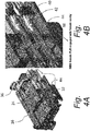
Fig. 2A is perceptive rear view of a male blade stabilizer of the male connector ofFig. 1C in accordance with the embodiment of the invention; -
Fig. 2B is perceptive front view of the male blade stabilizer ofFig. 2A in accordance with the embodiment of the invention; -
Fig. 3A is a cross section view of the male connector ofFig. 1C with the male blade stabilizer ofFig. 2A in a pre-staged position in accordance with the embodiment of the invention; -
Fig. 3B is a close-up cross section view ofFig. 3A showing the engagement of the male blade stabilizer with the terminals in the pre-staged position in accordance with the embodiment of the invention; -
Fig. 4A is a cross section view of the female connector ofFig. 1B engaged with the male connector ofFig. 1C with the male blade stabilizer ofFig. 2A in the pre-staged position in accordance with the embodiment of the invention; -
Fig. 4B is a close-up cross section view ofFig. 4A showing the engagement of the male blade stabilizer with the cavity in the female connector in accordance with the embodiment of the invention; -
Fig. 5A is a cross section view of the female connector ofFig. 1B engaged with the male connector ofFig. 1C as the male blade stabilizer moves from the pre-staged position to the staged position in accordance with the embodiment of the invention; -
Fig. 5B is a close-up cross section view ofFig. 5A showing the male primary lock retainer backing up the male cavities primary lock before terminals are mated in accordance with the embodiment of the invention; -
Fig. 6A is a cross section view of the female connector ofFig. 1B engaged with the male connector ofFig. 1C with the male blade stabilizer ofFig. 2A in the staged position in accordance with the embodiment of the invention; and -
Fig. 6B is a close-up cross section view ofFig. 5A showing the engagement of the male blade stabilizer with the female and male connector in accordance with the embodiment of the invention. - An electrical connector assembly is presented herein. The electrical connector assembly includes a terminal stabilizer that is configured to hold electrical terminals is proper spacing and alignment as the connectors of the electrical connector assembly are mated. Such a terminal stabilizer often referred to as a male blade stabilizer device since it is typically male blade terminals that require stabilization due to their elongated blades or pins. The terminal stabilizer also includes primary lock retention features that engage with the primary lock features that retain the terminals within the terminal cavities of the connectors. The lock retention features are configured to engage both the primary lock features that retain the male terminals within one connector body and the primary lock features that retain the female terminals within the other connector body.
-
Fig. 1A illustrates a non-limiting example of an electrical connector assembly, hereinafter referred to as theassembly 10, in accordance with one embodiment of the invention. Theassembly 10 includes twomating connectors Figs 1B and 1C . - A
first connector 12, shown inFig. 1C , includes afirst connector body 16 defining a plurality of firstterminal cavities 18 therein. Thefirst connector 12 also includes a plurality ofmale terminals 20 that project along a terminal axis to a tip and are disposed within the firstterminal cavities 18. Themale terminals 20 are secured within the firstterminal cavities 18 by first primary lock features 22 that are in the form of cantilevered arms with angled latches on the free ends that engage ledges on themale terminals 20 to secure themale terminals 20 within the firstterminal cavities 18. Thefirst connector 12 also includes aterminal stabilizer 24 shown inFigs 2A and 2B which defines a plurality ofapertures 26 in which themale terminals 20 are received. Theterminal stabilizer 24 is disposed within thefirst connector body 16 and moveable from apre-staged position 28 shown inFigs. 3A and 3B to a stagedposition 30 shown inFigs 6A and 6B . Theterminal stabilizer 24 is closer to the tips of themale terminals 20 when in thepre-staged position 28 than the stagedposition 30. - The
terminal stabilizer 24 defines a first primarylock retaining feature 32 that is configured to engage the first primary lock features 22 as theterminal stabilizer 24 moves from thepre-staged position 28 to the stagedposition 30. The first primarylock retaining feature 32 is situated between the first primary lock features 22 and a cavity wall of the firstterminal cavities 18 when theterminal stabilizer 24 is in the stagedposition 30, thereby inhibiting flexing of the first primary lock features 22 that could result in inadvertent removal of a male terminal 20 from one of the firstterminal cavities 18. - The first primary
lock retaining feature 32 is shaped, sized, and arranged so that it is not engaged with the first primary lock features 22 when theterminal stabilizer 24 is in thepre-staged position 28. The first primarylock retaining feature 32 is received within the firstterminal cavity 18 and positioned between the first primary lock features 22 and the cavity wall as theterminal stabilizer 24 is moved from thepre-staged position 28 to the stagedposition 30. The first primarylock retaining feature 32 is in the form of a first rib feature extending parallel to the terminal axis from a first face 34 of theterminal stabilizer 24 defining theapertures 26. - A
second connector 14, shown inFig. 1B , includes asecond connector body 36 defining a plurality of secondterminal cavities 38 therein. Thesecond connector body 36 is configured to mate with thefirst connector body 16. A plurality offemale terminals 40 are secured within the secondterminal cavities 38 by second primary lock features 42 that are similar in design and function to the first primary lock features 22. Thefemale terminals 40 are configured to mate with themale terminals 20. Theterminal stabilizer 24 defines a second primarylock retaining feature 44 that is configured to engage the second primary lock features 42 as theterminal stabilizer 24 moves from thepre-staged position 28 to the stagedposition 30 as thefirst connector body 16 is mated with thesecond connector body 36. When theterminal stabilizer 24 is in the stagedposition 30, the second primarylock retaining feature 44 is situated between the second primary lock features 42 and a cavity wall of the secondterminal cavities 38, thereby inhibiting flexing of the first primary lock features 22 that could result in inadvertent removal of a female terminal 40 from one of the secondterminal cavities 38. The second primarylock retaining feature 44 is in the form of a second rib feature that extends parallel to the terminal axis from asecond face 46 of theterminal stabilizer 24 defining theapertures 26 in a direction opposite to the first face 34. - The
second connector body 36 pushes theterminal stabilizer 24 from thepre-staged position 28 to the stagedposition 30 as thefirst connector body 16 is mated with thesecond connector body 36. - The
terminal stabilizer 24 defines pre-stage locking features 48 configured to retain theterminal stabilizer 24 in thepre-staged position 28 until pushed by thesecond connector body 36. - The first primary
lock retaining feature 32 engages the firstprimary lock feature 22 prior to mating themale terminal 20 with thefemale terminal 40 as shown inFigs. 5A and 5B . The second primarylock retaining feature 44 also engages the secondprimary lock feature 42 prior to mating themale terminal 20 with thefemale terminal 40 as shown inFigs. 4A and 4B . - The
terminal stabilizer 24 defines aretraction feature 50 configured to move theterminal stabilizer 24 from the stagedposition 30 to thepre-staged position 28 as thefirst connector body 16 is unmated from thesecond connector body 36. - During initial assembly, the
terminal stabilizer 24 is set in the pre-stage position within thefirst connector body 16. The first primary lock retention features are set at some distance from the first primary lock features 22 to allow the first primary lock features 22 to flex so that themale terminals 20 may plugged into the firstterminal cavities 18 without issues. During mating of thefirst connector 12 with thesecond connector 14, the second primary lock retainer feature goes between the second primary lock features 42 and the cavity wall of the secondterminal cavities 38 and reinforces second primary lock features 42 to make it a positive lock system. The female housing pushes theterminal stabilizer 24 all the way down to final position. - During the movement of the
terminal stabilizer 24 from thepre-staged position 28 to the stagedposition 30, the first primarylock retaining feature 32 backs up the first primary lock features 22 before themale terminals 20 start mating with thefemale terminals 40. This ensures that the first primary lock features 22 are very well reinforced before terminal engagement which can exert higher forces on the first primary lock features 22. - The primary lock retainer features on the
terminal stabilizer 24 can eliminate the need for secondary lock features that are typically used to reinforce or back up the primary lock features. With thisterminal stabilizer 24 both male and female secondary lock components can be eliminated from the connector design and provide the benefit of reduced overall cost for theelectrical connector assembly 10. - While the example presented herein is directed to an electrical connector assembly, other embodiments may be envisioned that are adapted for use with other types of connector assemblies for fiber optic cables, pneumatic tubes, hydraulic tubes, or a hybrid connector assembly including two or more of the items listed above.
- While this invention has been described in terms of the preferred embodiments thereof, it is not intended to be so limited, but rather only to the extent set forth in the claims that follow. For example, the above-described embodiments (and/or aspects thereof) may be used in combination with each other. In addition, many modifications may be made to configure a particular situation or material to the teachings of the invention without departing from its scope. Dimensions, types of materials, orientations of the various components, and the number and positions of the various components described herein are intended to define parameters of certain embodiments and are by no means limiting and are merely prototypical embodiments.
- Many other embodiments and modifications within the spirit and scope of the claims will be apparent to those of skill in the art upon reviewing the above description. The scope of the invention should, therefore, be determined with reference to the following claims, along with the full scope of equivalents to which such claims are entitled.
- As used herein, 'one or more' includes a function being performed by one element, a function being performed by more than one element, e.g., in a distributed fashion, several functions being performed by one element, several functions being performed by several elements, or any combination of the above.
- It will also be understood that, although the terms first, second, etc. are, in some instances, used herein to describe various elements, these elements should not be limited by these terms. These terms are only used to distinguish one element from another. For example, a first contact could be termed a second contact, and, similarly, a second contact could be termed a first contact, without departing from the scope of the various described embodiments. The first contact and the second contact are both contacts, but they are not the same contact.
- The terminology used in the description of the various described embodiments herein is for the purpose of describing embodiments only and is not intended to be limiting. As used in the description of the various described embodiments and the appended claims, the singular forms "a", "an" and "the" are intended to include the plural forms as well, unless the context clearly indicates otherwise. It will also be understood that the term "and/or" as used herein refers to and encompasses all possible combinations of one or more of the associated listed items. It will be further understood that the terms "includes," "including," "comprises," and/or "comprising," when used in this specification, specify the presence of stated features, integers, steps, operations, elements, and/or components, but do not preclude the presence or addition of one or more other features, integers, steps, operations, elements, components, and/or groups thereof.
- As used herein, the term "if' is, optionally, construed to mean "when" or "upon" or "in response to determining" or "in response to detecting," depending on the context. Similarly, the phrase "if it is determined" or "if [a stated condition or event] is detected" is, optionally, construed to mean "upon determining" or "in response to determining" or "upon detecting [the stated condition or event]" or "in response to detecting [the stated condition or event]," depending on the context.
- Additionally, while terms of ordinance or orientation may be used herein these elements should not be limited by these terms. All terms of ordinance or orientation, unless stated otherwise, are used for purposes distinguishing one element from another, and do not denote any particular order, order of operations, direction or orientation unless stated otherwise.
Claims (15)
- An electrical connector assembly (10), comprising:a connector body (16) defining a terminal cavity (18) therein;a male terminal (20) projecting along a terminal axis to a tip and secured within the terminal cavity (18) by a primary lock feature (22); anda terminal stabilizer (24) defining an aperture (26), disposed within the connector body (16), and moveable from a pre-staged position (28) to a staged position (30), wherein a primary lock retaining feature (32) is integrated with the terminal stabilizer (24) and configured to engage the primary lock feature (22) as the terminal stabilizer (24) moves from the pre-staged position (28) to the staged position (30).
- The electrical connector assembly (10) according to claim 1, wherein the tip of the male terminal (20) is received in the aperture (26).
- The electrical connector assembly (10) according to claim 2, wherein the terminal stabilizer (24) is closer to the tip in the pre-staged position (28) than the staged position (30).
- The electrical connector assembly (10) according to claim 1, wherein the primary lock retaining feature (32) is not engaged with the primary lock feature (22) when the terminal stabilizer (24) is in the pre-staged position (28).
- The electrical connector assembly (10) according to claim 1, wherein the primary lock retaining feature (32) is received within the terminal cavity (18) as the terminal stabilizer (24) is moved from the pre-staged position (28) to the staged position (30).
- The electrical connector assembly (10) according to claim 1, wherein the primary lock retaining feature (32) is a rib feature extending parallel to the terminal axis from a face (34) of the terminal stabilizer (24) defining the aperture (26).
- The electrical connector assembly (10) according to claim 6, wherein the connector body (16) is a first connector body (16), the terminal cavity (18) is a first terminal cavity (18), the primary lock feature (22) is a first primary lock feature (22), the rib feature is a first rib feature, and the face (34) is a first face (34) and wherein the electrical connector assembly (10) further comprises:a second connector body (36) defining a second terminal cavity (38) therein and configured to mate with the first connector body (16);a female terminal (40) secured within the second terminal cavity (38) by a second primary lock feature (42) and configured to mate with the male terminal (20), wherein the terminal stabilizer (24) defines a second primary lock retaining feature (44) configured to engage the second primary lock feature (42) as the terminal stabilizer (24) moves from the pre-staged position (28) to the staged position (30) as the first connector body (16) is mated with the second connector body (36).
- The electrical connector assembly (10) according to claim 7, wherein the second primary lock retaining feature (44) is a second rib feature extending parallel to the terminal axis from a second face (26) of the terminal stabilizer (24) defining the aperture (26) in a direction opposite to the first face (34).
- The electrical connector assembly (10) according to claim 7, wherein the second connector body (36) pushes the terminal stabilizer (24) from the pre-staged position (28) to the staged position (30) as the first connector body (16) is mated with the second connector body (36).
- The electrical connector assembly (10) according to claim 9, wherein the terminal stabilizer (24) defines pre-stage locking features (48) configured to retain the terminal stabilizer (24) in the pre-staged position (28) until pushed by the second connector body (36).
- The electrical connector assembly (10) according to claim 7, wherein the first primary lock retaining feature (32) engages the first primary lock feature (22) prior to mating the male terminal (20) with the female terminal (40).
- The electrical connector assembly (10) according to claim 7, wherein the second primary lock retaining (44) feature engages the second primary lock feature (42) prior to mating the male terminal (20) with the female terminal (40).
- The electrical connector assembly (10) according to claim 7, wherein the terminal stabilizer (24) defines a retraction feature (50) configured to move the terminal stabilizer (24) from the staged position (30) to the pre-staged position (28) as the first connector body (16) is unmated from the second connector body (36).
- A method of assembling an electrical connector (10) including a connector body (16) defining a terminal cavity (18) therein, a male terminal (20) projecting along a terminal axis to a tip and secured within the terminal cavity (18) by a primary lock feature (22), and a terminal stabilizer (24) defining an aperture (26) disposed within the connector body (16) and having a primary lock retaining feature (32) integrated with the terminal stabilizer (24), the method comprising:moving the terminal stabilizer (24) from a pre-staged position (28) to a staged position (30); andengaging the primary lock retaining feature (32) with the primary lock feature (22) as the terminal stabilizer (24) moves from the pre-staged position (28) to the staged position (30).
- The method according to claim 14, further comprising receiving the tip of the male terminal (20) in the aperture (26), wherein the terminal stabilizer (24) is closer to the tip in the pre-staged position (28) than the staged position (30).
Applications Claiming Priority (2)
| Application Number | Priority Date | Filing Date | Title |
|---|---|---|---|
| US202062961733P | 2020-01-16 | 2020-01-16 | |
| US17/127,135 US11502444B2 (en) | 2020-01-16 | 2020-12-18 | Electrical connector assembly having a male blade stabilizer with integrated primary lock reinforcement |
Publications (2)
| Publication Number | Publication Date |
|---|---|
| EP3852203A1 true EP3852203A1 (en) | 2021-07-21 |
| EP3852203B1 EP3852203B1 (en) | 2024-03-20 |
Family
ID=74105877
Family Applications (1)
| Application Number | Title | Priority Date | Filing Date |
|---|---|---|---|
| EP21150468.3A Active EP3852203B1 (en) | 2020-01-16 | 2021-01-07 | Electrical connector assembly having a male blade stabilizer with integrated primary lock reinforcement |
Country Status (3)
| Country | Link |
|---|---|
| US (1) | US11502444B2 (en) |
| EP (1) | EP3852203B1 (en) |
| CN (1) | CN113206406B (en) |
Families Citing this family (4)
| Publication number | Priority date | Publication date | Assignee | Title |
|---|---|---|---|---|
| US11881650B2 (en) * | 2020-12-21 | 2024-01-23 | Aptiv Technologies AG | Electrical connector assembly with male terminal stabilizer |
| EP4597760A1 (en) * | 2024-02-05 | 2025-08-06 | Aptiv Technologies AG | Position assurance member with facilitated removal |
| EP4597761A1 (en) * | 2024-02-05 | 2025-08-06 | Aptiv Technologies AG | Finger operated position assurance member |
| EP4597762A1 (en) * | 2024-02-05 | 2025-08-06 | Aptiv Technologies AG | Position assurance member |
Citations (2)
| Publication number | Priority date | Publication date | Assignee | Title |
|---|---|---|---|---|
| US4826452A (en) * | 1987-10-16 | 1989-05-02 | Altair International, Inc. | Two-part electrical connector |
| US7179136B1 (en) * | 2006-09-19 | 2007-02-20 | Delphi Technologies, Inc. | Electrical connector |
Family Cites Families (17)
| Publication number | Priority date | Publication date | Assignee | Title |
|---|---|---|---|---|
| JPH01213973A (en) * | 1988-02-23 | 1989-08-28 | Sumitomo Wiring Syst Ltd | Connector |
| FR2726402B1 (en) * | 1994-10-27 | 1996-12-06 | Cinch Connecteurs Sa | IMPROVEMENTS ON ELECTRICAL CONNECTORS |
| US5716234A (en) * | 1996-10-03 | 1998-02-10 | General Motors Corporation | Electrical connector with positive lock retention |
| JP2001085097A (en) * | 1999-09-16 | 2001-03-30 | Sumitomo Wiring Syst Ltd | Connector |
| KR200183163Y1 (en) * | 1999-12-14 | 2000-05-15 | 한국몰렉스주식회사 | Connector assembly for double lock electrical connection |
| US6761568B2 (en) | 2001-02-27 | 2004-07-13 | Delphi Technologies, Inc. | Electrical connector assembly |
| US7670177B2 (en) * | 2008-06-17 | 2010-03-02 | Tyco Electronics Corporation | Electrical connector having floating alignment member |
| US8267702B2 (en) | 2010-05-26 | 2012-09-18 | Delphi Technologies, Inc. | Electrical distribution center assembly having a terminal stabilizer integrally formed with a housing |
| US8038455B1 (en) | 2010-10-28 | 2011-10-18 | Delphi Technologies, Inc. | Connector assembly having retractable stabilizer including inward flexing securing member |
| US8926344B2 (en) | 2013-01-16 | 2015-01-06 | Delphi Technologies, Inc. | Electrical distribution center assembly having a terminal stabilizer plate |
| US9054454B2 (en) * | 2013-06-28 | 2015-06-09 | Delphi Technologies, Inc. | Electrical connector with a terminal stabilizer having an integrally formed arcuate resilient spring member |
| US9666972B2 (en) * | 2014-11-13 | 2017-05-30 | Te Connectivity Corporation | Electrical connector |
| US9472885B2 (en) * | 2014-12-08 | 2016-10-18 | Delphi Technologies, Inc. | Electrical connector assembly with low terminal insertion force |
| CN205051083U (en) * | 2015-07-24 | 2016-02-24 | 泰科电子(苏州)有限公司 | Connector |
| JP2017098222A (en) * | 2015-11-18 | 2017-06-01 | デルファイ・テクノロジーズ・インコーポレーテッド | Electric connector with terminal position assurance device |
| US10236629B2 (en) | 2017-05-08 | 2019-03-19 | Aptiv Technologies Limited | Electrical connector with retractable terminal-stabilizer |
| US10498066B1 (en) * | 2018-06-07 | 2019-12-03 | Delphi Technologies, Llc | Connector assembly with terminal-stabilizer |
-
2020
- 2020-12-18 US US17/127,135 patent/US11502444B2/en active Active
-
2021
- 2021-01-07 EP EP21150468.3A patent/EP3852203B1/en active Active
- 2021-01-15 CN CN202110053979.9A patent/CN113206406B/en active Active
Patent Citations (2)
| Publication number | Priority date | Publication date | Assignee | Title |
|---|---|---|---|---|
| US4826452A (en) * | 1987-10-16 | 1989-05-02 | Altair International, Inc. | Two-part electrical connector |
| US7179136B1 (en) * | 2006-09-19 | 2007-02-20 | Delphi Technologies, Inc. | Electrical connector |
Also Published As
| Publication number | Publication date |
|---|---|
| CN113206406A (en) | 2021-08-03 |
| US11502444B2 (en) | 2022-11-15 |
| CN113206406B (en) | 2025-12-05 |
| US20210226370A1 (en) | 2021-07-22 |
| EP3852203B1 (en) | 2024-03-20 |
Similar Documents
| Publication | Publication Date | Title |
|---|---|---|
| US11502444B2 (en) | Electrical connector assembly having a male blade stabilizer with integrated primary lock reinforcement | |
| EP3361578B1 (en) | Electrical connector with a terminal position assurance device | |
| EP2819248B1 (en) | Electrical connector with integrated moveable terminal stabilizer | |
| US11881650B2 (en) | Electrical connector assembly with male terminal stabilizer | |
| EP2235799B1 (en) | Electrical connector | |
| EP0895312B1 (en) | An electrical connector having a terminal position assurance device | |
| EP3944423A1 (en) | Coaxial connector assembly | |
| EP2975698B1 (en) | Electrical connector with a terminal position assurance device | |
| EP3220490B1 (en) | Connector position assurance device, connector housing and electrical connector system | |
| EP0382344B1 (en) | Reinforced connector latch | |
| EP4228100B1 (en) | Connector assembly with an unseated terminal detection feature | |
| EP3171459A1 (en) | Electrical connector with a terminal position assurance device | |
| US6247966B1 (en) | Electrical connector with exposed molded latches | |
| EP4297193A1 (en) | Electrical connector assembly with flexible and rigid terminal locking features | |
| US6116953A (en) | Electrical connector having a terminal position assurance device | |
| US11201428B2 (en) | Connector assembly with connector lock and terminal retainer | |
| US12562520B2 (en) | Connector assembly with terminal position assurance and blocking feature | |
| US9923303B2 (en) | Electrical connector with terminal centering system | |
| US20250316928A1 (en) | Connector having retention feature for lever and slide mating assist mechanism | |
| CN116581580A (en) | Connector assembly with dislocating terminal detection function | |
| CN118899711A (en) | Primary locking reinforcement for connector locking systems with resilient and rigid locking surfaces |
Legal Events
| Date | Code | Title | Description |
|---|---|---|---|
| PUAI | Public reference made under article 153(3) epc to a published international application that has entered the european phase |
Free format text: ORIGINAL CODE: 0009012 |
|
| STAA | Information on the status of an ep patent application or granted ep patent |
Free format text: STATUS: THE APPLICATION HAS BEEN PUBLISHED |
|
| AK | Designated contracting states |
Kind code of ref document: A1 Designated state(s): AL AT BE BG CH CY CZ DE DK EE ES FI FR GB GR HR HU IE IS IT LI LT LU LV MC MK MT NL NO PL PT RO RS SE SI SK SM TR |
|
| STAA | Information on the status of an ep patent application or granted ep patent |
Free format text: STATUS: REQUEST FOR EXAMINATION WAS MADE |
|
| 17P | Request for examination filed |
Effective date: 20220114 |
|
| RBV | Designated contracting states (corrected) |
Designated state(s): AL AT BE BG CH CY CZ DE DK EE ES FI FR GB GR HR HU IE IS IT LI LT LU LV MC MK MT NL NO PL PT RO RS SE SI SK SM TR |
|
| RAP3 | Party data changed (applicant data changed or rights of an application transferred) |
Owner name: APTIV TECHNOLOGIES LIMITED |
|
| GRAP | Despatch of communication of intention to grant a patent |
Free format text: ORIGINAL CODE: EPIDOSNIGR1 |
|
| STAA | Information on the status of an ep patent application or granted ep patent |
Free format text: STATUS: GRANT OF PATENT IS INTENDED |
|
| INTG | Intention to grant announced |
Effective date: 20231211 |
|
| GRAS | Grant fee paid |
Free format text: ORIGINAL CODE: EPIDOSNIGR3 |
|
| P01 | Opt-out of the competence of the unified patent court (upc) registered |
Effective date: 20240105 |
|
| GRAA | (expected) grant |
Free format text: ORIGINAL CODE: 0009210 |
|
| STAA | Information on the status of an ep patent application or granted ep patent |
Free format text: STATUS: THE PATENT HAS BEEN GRANTED |
|
| AK | Designated contracting states |
Kind code of ref document: B1 Designated state(s): AL AT BE BG CH CY CZ DE DK EE ES FI FR GB GR HR HU IE IS IT LI LT LU LV MC MK MT NL NO PL PT RO RS SE SI SK SM TR |
|
| REG | Reference to a national code |
Ref country code: GB Ref legal event code: FG4D |
|
| REG | Reference to a national code |
Ref country code: CH Ref legal event code: EP |
|
| REG | Reference to a national code |
Ref country code: DE Ref legal event code: R096 Ref document number: 602021010522 Country of ref document: DE |
|
| REG | Reference to a national code |
Ref country code: IE Ref legal event code: FG4D |
|
| PG25 | Lapsed in a contracting state [announced via postgrant information from national office to epo] |
Ref country code: LT Free format text: LAPSE BECAUSE OF FAILURE TO SUBMIT A TRANSLATION OF THE DESCRIPTION OR TO PAY THE FEE WITHIN THE PRESCRIBED TIME-LIMIT Effective date: 20240320 |
|
| REG | Reference to a national code |
Ref country code: LT Ref legal event code: MG9D |
|
| PG25 | Lapsed in a contracting state [announced via postgrant information from national office to epo] |
Ref country code: GR Free format text: LAPSE BECAUSE OF FAILURE TO SUBMIT A TRANSLATION OF THE DESCRIPTION OR TO PAY THE FEE WITHIN THE PRESCRIBED TIME-LIMIT Effective date: 20240621 |
|
| PG25 | Lapsed in a contracting state [announced via postgrant information from national office to epo] |
Ref country code: HR Free format text: LAPSE BECAUSE OF FAILURE TO SUBMIT A TRANSLATION OF THE DESCRIPTION OR TO PAY THE FEE WITHIN THE PRESCRIBED TIME-LIMIT Effective date: 20240320 Ref country code: RS Free format text: LAPSE BECAUSE OF FAILURE TO SUBMIT A TRANSLATION OF THE DESCRIPTION OR TO PAY THE FEE WITHIN THE PRESCRIBED TIME-LIMIT Effective date: 20240620 |
|
| REG | Reference to a national code |
Ref country code: NL Ref legal event code: MP Effective date: 20240320 |
|
| PG25 | Lapsed in a contracting state [announced via postgrant information from national office to epo] |
Ref country code: RS Free format text: LAPSE BECAUSE OF FAILURE TO SUBMIT A TRANSLATION OF THE DESCRIPTION OR TO PAY THE FEE WITHIN THE PRESCRIBED TIME-LIMIT Effective date: 20240620 Ref country code: NO Free format text: LAPSE BECAUSE OF FAILURE TO SUBMIT A TRANSLATION OF THE DESCRIPTION OR TO PAY THE FEE WITHIN THE PRESCRIBED TIME-LIMIT Effective date: 20240620 Ref country code: LT Free format text: LAPSE BECAUSE OF FAILURE TO SUBMIT A TRANSLATION OF THE DESCRIPTION OR TO PAY THE FEE WITHIN THE PRESCRIBED TIME-LIMIT Effective date: 20240320 Ref country code: HR Free format text: LAPSE BECAUSE OF FAILURE TO SUBMIT A TRANSLATION OF THE DESCRIPTION OR TO PAY THE FEE WITHIN THE PRESCRIBED TIME-LIMIT Effective date: 20240320 Ref country code: GR Free format text: LAPSE BECAUSE OF FAILURE TO SUBMIT A TRANSLATION OF THE DESCRIPTION OR TO PAY THE FEE WITHIN THE PRESCRIBED TIME-LIMIT Effective date: 20240621 Ref country code: FI Free format text: LAPSE BECAUSE OF FAILURE TO SUBMIT A TRANSLATION OF THE DESCRIPTION OR TO PAY THE FEE WITHIN THE PRESCRIBED TIME-LIMIT Effective date: 20240320 Ref country code: BG Free format text: LAPSE BECAUSE OF FAILURE TO SUBMIT A TRANSLATION OF THE DESCRIPTION OR TO PAY THE FEE WITHIN THE PRESCRIBED TIME-LIMIT Effective date: 20240320 |
|
| REG | Reference to a national code |
Ref country code: AT Ref legal event code: MK05 Ref document number: 1668669 Country of ref document: AT Kind code of ref document: T Effective date: 20240320 |
|
| PG25 | Lapsed in a contracting state [announced via postgrant information from national office to epo] |
Ref country code: SE Free format text: LAPSE BECAUSE OF FAILURE TO SUBMIT A TRANSLATION OF THE DESCRIPTION OR TO PAY THE FEE WITHIN THE PRESCRIBED TIME-LIMIT Effective date: 20240320 Ref country code: LV Free format text: LAPSE BECAUSE OF FAILURE TO SUBMIT A TRANSLATION OF THE DESCRIPTION OR TO PAY THE FEE WITHIN THE PRESCRIBED TIME-LIMIT Effective date: 20240320 |
|
| PG25 | Lapsed in a contracting state [announced via postgrant information from national office to epo] |
Ref country code: NL Free format text: LAPSE BECAUSE OF FAILURE TO SUBMIT A TRANSLATION OF THE DESCRIPTION OR TO PAY THE FEE WITHIN THE PRESCRIBED TIME-LIMIT Effective date: 20240320 |
|
| PG25 | Lapsed in a contracting state [announced via postgrant information from national office to epo] |
Ref country code: NL Free format text: LAPSE BECAUSE OF FAILURE TO SUBMIT A TRANSLATION OF THE DESCRIPTION OR TO PAY THE FEE WITHIN THE PRESCRIBED TIME-LIMIT Effective date: 20240320 |
|
| PG25 | Lapsed in a contracting state [announced via postgrant information from national office to epo] |
Ref country code: IS Free format text: LAPSE BECAUSE OF FAILURE TO SUBMIT A TRANSLATION OF THE DESCRIPTION OR TO PAY THE FEE WITHIN THE PRESCRIBED TIME-LIMIT Effective date: 20240720 |
|
| PG25 | Lapsed in a contracting state [announced via postgrant information from national office to epo] |
Ref country code: PT Free format text: LAPSE BECAUSE OF FAILURE TO SUBMIT A TRANSLATION OF THE DESCRIPTION OR TO PAY THE FEE WITHIN THE PRESCRIBED TIME-LIMIT Effective date: 20240722 Ref country code: SM Free format text: LAPSE BECAUSE OF FAILURE TO SUBMIT A TRANSLATION OF THE DESCRIPTION OR TO PAY THE FEE WITHIN THE PRESCRIBED TIME-LIMIT Effective date: 20240320 |
|
| PG25 | Lapsed in a contracting state [announced via postgrant information from national office to epo] |
Ref country code: ES Free format text: LAPSE BECAUSE OF FAILURE TO SUBMIT A TRANSLATION OF THE DESCRIPTION OR TO PAY THE FEE WITHIN THE PRESCRIBED TIME-LIMIT Effective date: 20240320 |
|
| PG25 | Lapsed in a contracting state [announced via postgrant information from national office to epo] |
Ref country code: CZ Free format text: LAPSE BECAUSE OF FAILURE TO SUBMIT A TRANSLATION OF THE DESCRIPTION OR TO PAY THE FEE WITHIN THE PRESCRIBED TIME-LIMIT Effective date: 20240320 Ref country code: EE Free format text: LAPSE BECAUSE OF FAILURE TO SUBMIT A TRANSLATION OF THE DESCRIPTION OR TO PAY THE FEE WITHIN THE PRESCRIBED TIME-LIMIT Effective date: 20240320 |
|
| PG25 | Lapsed in a contracting state [announced via postgrant information from national office to epo] |
Ref country code: AT Free format text: LAPSE BECAUSE OF FAILURE TO SUBMIT A TRANSLATION OF THE DESCRIPTION OR TO PAY THE FEE WITHIN THE PRESCRIBED TIME-LIMIT Effective date: 20240320 |
|
| PG25 | Lapsed in a contracting state [announced via postgrant information from national office to epo] |
Ref country code: PL Free format text: LAPSE BECAUSE OF FAILURE TO SUBMIT A TRANSLATION OF THE DESCRIPTION OR TO PAY THE FEE WITHIN THE PRESCRIBED TIME-LIMIT Effective date: 20240320 |
|
| PG25 | Lapsed in a contracting state [announced via postgrant information from national office to epo] |
Ref country code: SK Free format text: LAPSE BECAUSE OF FAILURE TO SUBMIT A TRANSLATION OF THE DESCRIPTION OR TO PAY THE FEE WITHIN THE PRESCRIBED TIME-LIMIT Effective date: 20240320 |
|
| PG25 | Lapsed in a contracting state [announced via postgrant information from national office to epo] |
Ref country code: SM Free format text: LAPSE BECAUSE OF FAILURE TO SUBMIT A TRANSLATION OF THE DESCRIPTION OR TO PAY THE FEE WITHIN THE PRESCRIBED TIME-LIMIT Effective date: 20240320 Ref country code: SK Free format text: LAPSE BECAUSE OF FAILURE TO SUBMIT A TRANSLATION OF THE DESCRIPTION OR TO PAY THE FEE WITHIN THE PRESCRIBED TIME-LIMIT Effective date: 20240320 Ref country code: RO Free format text: LAPSE BECAUSE OF FAILURE TO SUBMIT A TRANSLATION OF THE DESCRIPTION OR TO PAY THE FEE WITHIN THE PRESCRIBED TIME-LIMIT Effective date: 20240320 Ref country code: PT Free format text: LAPSE BECAUSE OF FAILURE TO SUBMIT A TRANSLATION OF THE DESCRIPTION OR TO PAY THE FEE WITHIN THE PRESCRIBED TIME-LIMIT Effective date: 20240722 Ref country code: PL Free format text: LAPSE BECAUSE OF FAILURE TO SUBMIT A TRANSLATION OF THE DESCRIPTION OR TO PAY THE FEE WITHIN THE PRESCRIBED TIME-LIMIT Effective date: 20240320 Ref country code: IS Free format text: LAPSE BECAUSE OF FAILURE TO SUBMIT A TRANSLATION OF THE DESCRIPTION OR TO PAY THE FEE WITHIN THE PRESCRIBED TIME-LIMIT Effective date: 20240720 Ref country code: ES Free format text: LAPSE BECAUSE OF FAILURE TO SUBMIT A TRANSLATION OF THE DESCRIPTION OR TO PAY THE FEE WITHIN THE PRESCRIBED TIME-LIMIT Effective date: 20240320 Ref country code: EE Free format text: LAPSE BECAUSE OF FAILURE TO SUBMIT A TRANSLATION OF THE DESCRIPTION OR TO PAY THE FEE WITHIN THE PRESCRIBED TIME-LIMIT Effective date: 20240320 Ref country code: CZ Free format text: LAPSE BECAUSE OF FAILURE TO SUBMIT A TRANSLATION OF THE DESCRIPTION OR TO PAY THE FEE WITHIN THE PRESCRIBED TIME-LIMIT Effective date: 20240320 Ref country code: AT Free format text: LAPSE BECAUSE OF FAILURE TO SUBMIT A TRANSLATION OF THE DESCRIPTION OR TO PAY THE FEE WITHIN THE PRESCRIBED TIME-LIMIT Effective date: 20240320 |
|
| PG25 | Lapsed in a contracting state [announced via postgrant information from national office to epo] |
Ref country code: IT Free format text: LAPSE BECAUSE OF FAILURE TO SUBMIT A TRANSLATION OF THE DESCRIPTION OR TO PAY THE FEE WITHIN THE PRESCRIBED TIME-LIMIT Effective date: 20240320 |
|
| REG | Reference to a national code |
Ref country code: DE Ref legal event code: R097 Ref document number: 602021010522 Country of ref document: DE |
|
| PG25 | Lapsed in a contracting state [announced via postgrant information from national office to epo] |
Ref country code: IT Free format text: LAPSE BECAUSE OF FAILURE TO SUBMIT A TRANSLATION OF THE DESCRIPTION OR TO PAY THE FEE WITHIN THE PRESCRIBED TIME-LIMIT Effective date: 20240320 |
|
| PG25 | Lapsed in a contracting state [announced via postgrant information from national office to epo] |
Ref country code: DK Free format text: LAPSE BECAUSE OF FAILURE TO SUBMIT A TRANSLATION OF THE DESCRIPTION OR TO PAY THE FEE WITHIN THE PRESCRIBED TIME-LIMIT Effective date: 20240320 |
|
| PLBE | No opposition filed within time limit |
Free format text: ORIGINAL CODE: 0009261 |
|
| STAA | Information on the status of an ep patent application or granted ep patent |
Free format text: STATUS: NO OPPOSITION FILED WITHIN TIME LIMIT |
|
| PG25 | Lapsed in a contracting state [announced via postgrant information from national office to epo] |
Ref country code: DK Free format text: LAPSE BECAUSE OF FAILURE TO SUBMIT A TRANSLATION OF THE DESCRIPTION OR TO PAY THE FEE WITHIN THE PRESCRIBED TIME-LIMIT Effective date: 20240320 |
|
| 26N | No opposition filed |
Effective date: 20241223 |
|
| PG25 | Lapsed in a contracting state [announced via postgrant information from national office to epo] |
Ref country code: SI Free format text: LAPSE BECAUSE OF FAILURE TO SUBMIT A TRANSLATION OF THE DESCRIPTION OR TO PAY THE FEE WITHIN THE PRESCRIBED TIME-LIMIT Effective date: 20240320 |
|
| REG | Reference to a national code |
Ref country code: DE Ref legal event code: R081 Ref document number: 602021010522 Country of ref document: DE Owner name: APTIV TECHNOLOGIES AG, CH Free format text: FORMER OWNER: APTIV TECHNOLOGIES LIMITED, ST. MICHAEL, BB |
|
| REG | Reference to a national code |
Ref country code: CH Ref legal event code: PL |
|
| PG25 | Lapsed in a contracting state [announced via postgrant information from national office to epo] |
Ref country code: LU Free format text: LAPSE BECAUSE OF NON-PAYMENT OF DUE FEES Effective date: 20250107 Ref country code: MC Free format text: LAPSE BECAUSE OF FAILURE TO SUBMIT A TRANSLATION OF THE DESCRIPTION OR TO PAY THE FEE WITHIN THE PRESCRIBED TIME-LIMIT Effective date: 20240320 |
|
| PG25 | Lapsed in a contracting state [announced via postgrant information from national office to epo] |
Ref country code: BE Free format text: LAPSE BECAUSE OF NON-PAYMENT OF DUE FEES Effective date: 20250131 |
|
| PG25 | Lapsed in a contracting state [announced via postgrant information from national office to epo] |
Ref country code: CH Free format text: LAPSE BECAUSE OF NON-PAYMENT OF DUE FEES Effective date: 20250131 |
|
| REG | Reference to a national code |
Ref country code: BE Ref legal event code: MM Effective date: 20250131 |
|
| PGFP | Annual fee paid to national office [announced via postgrant information from national office to epo] |
Ref country code: GB Payment date: 20251210 Year of fee payment: 6 |
|
| PGFP | Annual fee paid to national office [announced via postgrant information from national office to epo] |
Ref country code: FR Payment date: 20251202 Year of fee payment: 6 |
|
| PG25 | Lapsed in a contracting state [announced via postgrant information from national office to epo] |
Ref country code: IE Free format text: LAPSE BECAUSE OF NON-PAYMENT OF DUE FEES Effective date: 20250107 |
|
| PGFP | Annual fee paid to national office [announced via postgrant information from national office to epo] |
Ref country code: DE Payment date: 20251217 Year of fee payment: 6 |