EP3851932A1 - Method and system for regulating oil flow to an engine - Google Patents
Method and system for regulating oil flow to an engine Download PDFInfo
- Publication number
- EP3851932A1 EP3851932A1 EP21152107.5A EP21152107A EP3851932A1 EP 3851932 A1 EP3851932 A1 EP 3851932A1 EP 21152107 A EP21152107 A EP 21152107A EP 3851932 A1 EP3851932 A1 EP 3851932A1
- Authority
- EP
- European Patent Office
- Prior art keywords
- engine
- oil
- oil pressure
- pressure
- pressure target
- Prior art date
- Legal status (The legal status is an assumption and is not a legal conclusion. Google has not performed a legal analysis and makes no representation as to the accuracy of the status listed.)
- Withdrawn
Links
- 238000000034 method Methods 0.000 title claims abstract description 33
- 230000001105 regulatory effect Effects 0.000 title claims abstract description 17
- 230000001276 controlling effect Effects 0.000 claims abstract description 19
- 230000006870 function Effects 0.000 claims description 11
- 238000012545 processing Methods 0.000 claims description 11
- 238000005461 lubrication Methods 0.000 description 8
- 239000012530 fluid Substances 0.000 description 7
- 239000003570 air Substances 0.000 description 3
- 238000005516 engineering process Methods 0.000 description 3
- 230000008859 change Effects 0.000 description 2
- 239000000567 combustion gas Substances 0.000 description 2
- 238000004590 computer program Methods 0.000 description 2
- 239000007789 gas Substances 0.000 description 2
- 238000012986 modification Methods 0.000 description 2
- 230000004048 modification Effects 0.000 description 2
- 230000003287 optical effect Effects 0.000 description 2
- 230000004044 response Effects 0.000 description 2
- 239000012080 ambient air Substances 0.000 description 1
- 238000004891 communication Methods 0.000 description 1
- 238000011109 contamination Methods 0.000 description 1
- 239000000446 fuel Substances 0.000 description 1
- 230000006872 improvement Effects 0.000 description 1
- 238000012423 maintenance Methods 0.000 description 1
- 230000007246 mechanism Effects 0.000 description 1
- 238000012552 review Methods 0.000 description 1
- 239000004065 semiconductor Substances 0.000 description 1
Images


Classifications
-
- G—PHYSICS
- G05—CONTROLLING; REGULATING
- G05D—SYSTEMS FOR CONTROLLING OR REGULATING NON-ELECTRIC VARIABLES
- G05D16/00—Control of fluid pressure
- G05D16/20—Control of fluid pressure characterised by the use of electric means
- G05D16/2006—Control of fluid pressure characterised by the use of electric means with direct action of electric energy on controlling means
- G05D16/2066—Control of fluid pressure characterised by the use of electric means with direct action of electric energy on controlling means using controlling means acting on the pressure source
-
- F—MECHANICAL ENGINEERING; LIGHTING; HEATING; WEAPONS; BLASTING
- F02—COMBUSTION ENGINES; HOT-GAS OR COMBUSTION-PRODUCT ENGINE PLANTS
- F02C—GAS-TURBINE PLANTS; AIR INTAKES FOR JET-PROPULSION PLANTS; CONTROLLING FUEL SUPPLY IN AIR-BREATHING JET-PROPULSION PLANTS
- F02C7/00—Features, components parts, details or accessories, not provided for in, or of interest apart form groups F02C1/00 - F02C6/00; Air intakes for jet-propulsion plants
- F02C7/06—Arrangements of bearings; Lubricating
-
- F—MECHANICAL ENGINEERING; LIGHTING; HEATING; WEAPONS; BLASTING
- F01—MACHINES OR ENGINES IN GENERAL; ENGINE PLANTS IN GENERAL; STEAM ENGINES
- F01D—NON-POSITIVE DISPLACEMENT MACHINES OR ENGINES, e.g. STEAM TURBINES
- F01D21/00—Shutting-down of machines or engines, e.g. in emergency; Regulating, controlling, or safety means not otherwise provided for
- F01D21/003—Arrangements for testing or measuring
-
- F—MECHANICAL ENGINEERING; LIGHTING; HEATING; WEAPONS; BLASTING
- F01—MACHINES OR ENGINES IN GENERAL; ENGINE PLANTS IN GENERAL; STEAM ENGINES
- F01D—NON-POSITIVE DISPLACEMENT MACHINES OR ENGINES, e.g. STEAM TURBINES
- F01D25/00—Component parts, details, or accessories, not provided for in, or of interest apart from, other groups
- F01D25/18—Lubricating arrangements
- F01D25/20—Lubricating arrangements using lubrication pumps
-
- F—MECHANICAL ENGINEERING; LIGHTING; HEATING; WEAPONS; BLASTING
- F01—MACHINES OR ENGINES IN GENERAL; ENGINE PLANTS IN GENERAL; STEAM ENGINES
- F01M—LUBRICATING OF MACHINES OR ENGINES IN GENERAL; LUBRICATING INTERNAL COMBUSTION ENGINES; CRANKCASE VENTILATING
- F01M1/00—Pressure lubrication
- F01M1/16—Controlling lubricant pressure or quantity
-
- F—MECHANICAL ENGINEERING; LIGHTING; HEATING; WEAPONS; BLASTING
- F02—COMBUSTION ENGINES; HOT-GAS OR COMBUSTION-PRODUCT ENGINE PLANTS
- F02C—GAS-TURBINE PLANTS; AIR INTAKES FOR JET-PROPULSION PLANTS; CONTROLLING FUEL SUPPLY IN AIR-BREATHING JET-PROPULSION PLANTS
- F02C9/00—Controlling gas-turbine plants; Controlling fuel supply in air- breathing jet-propulsion plants
- F02C9/16—Control of working fluid flow
- F02C9/24—Control of the pressure level in closed cycles
-
- F—MECHANICAL ENGINEERING; LIGHTING; HEATING; WEAPONS; BLASTING
- F05—INDEXING SCHEMES RELATING TO ENGINES OR PUMPS IN VARIOUS SUBCLASSES OF CLASSES F01-F04
- F05D—INDEXING SCHEME FOR ASPECTS RELATING TO NON-POSITIVE-DISPLACEMENT MACHINES OR ENGINES, GAS-TURBINES OR JET-PROPULSION PLANTS
- F05D2260/00—Function
- F05D2260/98—Lubrication
Definitions
- the present disclosure relates generally to engines, and, more particularly, to methods and systems for regulating oil flow to an engine.
- an oil pump When an engine is operated, an oil pump may be used to provide oil to various parts of the engine.
- the oil pressure of the engine may be set at a predetermined value and when the oil pressure falls below the predetermined value, an indicator may display a warning in a cockpit of an aircraft. There is room for improvement.
- a method for regulating oil flow to an engine comprises determining an oil pressure target for the engine based on one or more engine operating parameters, controlling oil flow to the engine based on the oil pressure target, obtaining closed-loop feedback of oil pressure of the engine from at least one sensor during the controlling of the oil flow to the engine, determining a pressure difference between the oil pressure target and the closed-loop feedback of the oil pressure of the engine, and adjusting the oil flow to the engine based on the pressure difference.
- determining the oil pressure target comprises determining the oil pressure target based on the one or more engine operating parameters and a mode of operation of the engine.
- the mode of operation corresponds to any one of: flight idle, ground idle, forward thrust and reverse thrust.
- determining the oil pressure target comprises obtaining the oil pressure target from an oil pressure map indicating oil pressure as a function of engine rotational speed.
- the one or more engine operating parameters comprise any one or more of: atmospheric pressure, atmospheric temperature, oil temperature, engine rotational speed and engine filter conditions.
- controlling oil flow to the engine based on the oil pressure target comprises commanding a torque motor based on the oil pressure target to adjust a pressure valve adapted to control the oil flow to the engine.
- adjusting the oil flow to the engine based on the pressure difference comprises commanding the torque motor based on the pressure difference to adjust the pressure valve.
- an engine controller for regulating oil pressure to an engine.
- the engine controller comprises at least one processing unit and at least one non-transitory computer-readable memory having stored thereon program instructions.
- the program instructions are executable by the at least one processing unit for determining an oil pressure target for the engine based on one or more engine operating parameters, controlling oil flow to the engine based on the oil pressure target, obtaining closed-loop feedback of oil pressure of the engine from at least one sensor during the controlling of the oil flow to the engine, determining a pressure difference between the oil pressure target and the closed-loop feedback of the oil pressure of the engine, and adjusting the oil flow to the engine based on the pressure difference.
- determining the oil pressure target comprises determining the oil pressure target based on the one or more engine operating parameters and a mode of operation of the engine.
- the mode of operation corresponds to any one of: flight idle, ground idle, forward thrust and reverse thrust.
- determining the oil pressure target comprises obtaining the oil pressure target from an oil pressure map indicating oil pressure as a function of engine rotational speed.
- the one or more engine operating parameters comprise any one or more of: atmospheric pressure, atmospheric temperature, oil temperature, engine rotational speed and engine filter conditions.
- controlling oil flow to the engine based on the oil pressure target comprises commanding a torque motor based on the oil pressure target to adjust a pressure valve adapted to control the oil flow to the engine.
- adjusting the oil flow to the engine based on the pressure difference comprises commanding the torque motor based on the pressure difference to adjust the pressure valve.
- a system for regulating oil pressure to an engine comprising a pressure valve adapted for controlling oil flow in a fluid circuit of the engine, a torque motor coupled to the pressure valve for controlling the pressure valve, at least one sensor configured for measuring oil pressure in the fluid circuit, and an engine controller connected to the torque motor and to the at least one sensor.
- the engine controller is configured for determining an oil pressure target for the engine based on one or more engine operating parameters, commanding the torque motor to control oil flow to the engine based on the oil pressure target, obtaining closed-loop feedback of oil pressure of the engine from the at least one sensor during the control of the oil flow to the engine, determining a pressure difference between the oil pressure target and the closed-loop feedback of the oil pressure of the engine, and commanding the torque motor to adjust the oil flow to the engine based on the pressure difference.
- determining the oil pressure target comprises determining the oil pressure target based on the one or more engine operating parameters and a mode of operation of the engine.
- the mode of operation corresponds to any one of: flight idle, ground idle, forward thrust and reverse thrust.
- determining the oil pressure target comprises obtaining the oil pressure target from an oil pressure map indicating oil pressure as a function of engine rotational speed.
- the one or more engine operating parameters comprise any one or more of: atmospheric pressure, atmospheric temperature, oil temperature, engine rotational speed and engine filter conditions.
- the pressure valve is a three-way valve.
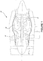
- FIG 1 illustrates a gas turbine engine 10, which an oil flow thereof may be regulated with the systems and methods described herein.
- the engine 10 generally comprising in serial flow communication a fan 12 through which ambient air is propelled, a compressor section 14 for pressurizing the air, a combustor 16 in which the compressed air is mixed with fuel and ignited for generating an annular stream of hot combustion gases, and a turbine section 18 for extracting energy from the combustion gases.
- engine 10 is a turbofan engine
- the systems and methods for regulating oil flow to an engine may be applicable to turboprop engines, turboshaft engines, or other suitable types of engines (e.g., aircraft engines, automotive engines, industrial engines, etc.).
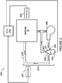
- the system 200 comprises an electronic engine controller (EEC) 210.
- the EEC 210 is configured to determine an oil pressure target for the engine 10 based on one or more engine operating parameters.
- the EEC 210 is configured to control oil flow to the engine 10 based on the oil pressure target.
- the EEC 210 is configured to obtain closed-loop feedback of the oil pressure of the engine 10 from at least one sensor 220 during the control of the oil flow to the engine 10.
- the EEC 210 is configured to determine a pressure difference between the oil pressure target and the closed-loop feedback of the oil pressure of the engine 10.
- the EEC 210 is configured to adjust the oil flow to the engine 10 based on the pressure difference.
- the sensor(s) 220 may be any suitable sensor(s) for measuring oil pressure. While the sensor(s) 220 are shown separate from a lubrication system 215 of the engine 10, this is for example purposes only. The sensor(s) 220 may be integrated into the lubrication system 215 at any suitable position of the lubrication system 215. The sensor(s) 220 may be part of the system 200 or may be separate from the system 200.
- the closed-loop feedback of the oil pressure of the engine 10 may be continuously received (e.g., in real time) and/or may be received in accordance with any suitable time interval or irregularly.
- the sensor(s) 220 may be connected to the EEC 210 to provide the closed-loop feedback of the oil pressure of the engine 10 to the EEC 210.
- the closed-loop feedback of the oil pressure of the engine 10 may be provided by one or more aircraft or/and engine computers and/or by any other suitable intermediary device(s).
- the aircraft and/or engine computer(s) and/or intermediary device(s) may be configured for obtaining the closed-loop feedback of the oil pressure of the engine 10 from the sensor(s) 220.
- the closed-loop feedback of the oil pressure of the engine 10 corresponds to the actual oil pressure of the engine 10.
- the closed-loop feedback of the oil pressure may vary from the oil pressure target.
- the engine operating parameters may be obtained in any suitable manner.
- the engine operating parameters may be obtained from one or more sensors 230 connected to the EEC 210. While the sensor(s) 230 are shown separate from the engine 10 this is for example purposes only.
- the sensor(s) 230 may be any suitable sensors for measuring one or more engine operating parameters.
- One or more of the sensors 230 may be engine sensors coupled to the engine 10.
- One or more of the sensors 230 may be aircraft sensors coupled to the aircraft.
- the sensor(s) 230 may be part of the system 200 or may be separate from the system 200.
- the engine operating parameters may be continuously received (e.g., in real time) and/or may be received in accordance with any suitable time interval or irregularly.
- one or more of the engine operating parameters may be provided by one or more aircraft or/and engine computers and/or by any other suitable intermediary device(s).
- the aircraft and/or engine computer(s) and/or intermediary device(s) may be configured for obtaining the engine operating parameters from the sensor(s) 230.
- one or more of the engine operating parameters may be generated by the EEC 210 based on measured operating engine parameter(s).
- the engine operating parameter(s) may comprise any one or more of: atmospheric pressure, atmospheric temperature, oil temperature, engine rotational speed, engine filter conditions and any other suitable engine operating parameters. While the EEC 210 is illustrated as separate from the engine 10, in some embodiments, the EEC 210 may be provided as part of the engine 10 and/or coupled to the engine 10.
- the oil pressure target may be determined in any suitable manner from the engine operating parameter(s).
- One or more functions, equations, maps, look-up tables, algorithms and/or the like may be used to determine the oil pressure target.
- the oil pressure target corresponds to the desired oil pressure for the engine 10.
- the oil pressure target may vary depending on a mode of operation of the engine 10 and/or on a mode of operation of an aircraft that is operating with the engine 10. Accordingly, the oil pressure target may be determined from the engine operating parameter(s) and the mode of operation.
- the mode of operation may correspond to an operating mode set by a power lever of an aircraft.
- the mode of operation may correspond to any one of: flight idle, ground idle, forward thrust, maximum forward thrust, reverse thrust, maximum reverse thrust, and any other suitable mode of operation.
- the mode of operation may correspond to a flight condition of an aircraft.
- the flight condition may correspond to any one of: take-off, climb, go-around, cruise, descent, landing or any other suitable flight condition of the aircraft.
- the oil pressure target is determined by obtaining the oil pressure target from an oil pressure map indicating oil pressure as a function of at least one engine operating parameter.
- the EEC 210 may have stored therein a plurality of oil pressure maps.
- One of the oil pressure maps may be selected based on one or more of the engine operating parameters and/or based on the mode of operation.
- each one of a plurality of oil pressure maps may correspond to a different oil temperature (or a different range of oil temperatures) and one of the oil pressure maps may be selected based on the oil temperature.
- each one of a plurality of oil pressure maps may correspond to a different mode of operation and one of the oil pressure maps may be selected based on the current mode of operation.
- the selected oil pressure map may vary as a function of engine rotational speed and the oil pressure target may be determined from the selected oil pressure map based on the rotational speed of the engine 10.
- Any suitable oil pressure map may be used which receives one or more of the engine operating parameter(s) as input parameters to the map and is used to obtain the oil pressure target therefrom.
- the lubrication system 215 comprises a pressure adjustable valve 240 adapted to control the oil flow to the engine 10 and a torque motor 250 coupled to the valve 240 for controlling the valve 240.
- Any suitable control mechanism may be controlled by the EEC 210 for regulating oil flow to the engine 10, and the valve 240 and the torque motor 250 combination is one possible implementation.
- An oil pump 260 circulates oil to the engine 10 via a fluid circuit 270.
- the fluid circuit 270 may comprise any suitable oil lines, passageways and/or the like for providing the oil to the engine 10.
- the oil pump 260 is configured to obtain oil from an oil reservoir configured for holding the oil.
- the oil pump 260 is configured to provide the oil to the valve 240.
- the valve 240 may be controlled in order to adjust the oil pressure and the quantity of oil provided to the engine 10.
- the EEC 210 may command the torque motor 250 based on the oil pressure target for adjusting the valve 240 to regulate the oil flow.
- the valve 240 is controlled in order to adjust the oil pressure towards the oil pressure target.
- the actual oil pressure after the valve 240 is adjusted may be different from the oil pressure target.
- the EEC 210 may command the torque motor 250 based on the pressure difference for adjusting the valve 240 to regulate the oil flow.
- the adjusting of the valve 240 based on the pressure difference may be continuously performed (e.g., in real time) and/or may be performed in accordance with any suitable time interval or irregularly in order to minimize the difference between the oil pressure target and the actual oil pressure.
- the valve 240 is a three-way valve.
- the pump 260 may provide oil to a first port 241 of the three-way valve 240 at a given pressure and the three-way valve 240 may be controlled to reduce the pressure of the oil provided by a second port 242 of the valve 240 that provides the oil to the engine 10. Oil may be returned from a third port 243 of the three-way valve 240 to the pump 260 and/or the oil reservoir.
- the configuration of the valve 240 may vary depending on practical implementations.
- the oil may be returned from the engine 10 via the fluid circuit 270 to the pump 260 and/or the oil reservoir.
- the lubrication system 215 and/or one or more aspects of the lubrication system 215 may be provided as part of the system 200.
- the sensor(s) 220 may be configured for measuring oil pressure in the fluid circuit 270.
- the sensor(s) 220 may be integrated into the fluid circuit 270 at any suitable position.
- the lubrication system 215 may vary depending on practical implementations.
- the lubrication system 215 may be implemented with any suitable oil pressure supply and oil scavenge system.
- the EEC 210 may control shutoff of the oil to the engine 10 by commanding the torque motor 250 to close the valve 240 during certain modes of operation of the engine and/or aircraft.
- the valve 240 may be closed to prevent cabin air contamination.
- FIG. 3 there is shown a flowchart illustrating an example method 300 for regulating oil flow to an engine.
- the method 300 may be implemented by any suitable engine controller, such as the EEC 210, or may be implemented by any other suitable engine and/or aircraft computer. While the method 300 is described herein with reference to the engine 10 of Figure 1 and aspects of Figure 2 this is for example purposes only.
- an oil pressure target for the engine 10 is determined based on one or more engine operating parameters.
- the engine operating parameter(s) may be obtained in any suitable manner.
- the engine operating parameter(s) may comprise any one or more of: atmospheric pressure, atmospheric temperature, oil temperature, engine rotational speed and engine filter conditions.
- the oil pressure target may be determined in any suitable manner.
- determining the oil pressure target comprises determining the oil pressure target based on the engine operating parameter(s) and a mode of operation of the engine 10.
- the mode of operation may correspond to any one of: flight idle, ground idle, forward thrust and reverse thrust.
- determining the oil pressure target comprises determining the oil pressure target based on the engine operating parameter(s) and a flight condition.
- the flight condition may correspond to any one of: take-off, climb, go-around, cruise, descent, landing or any other suitable flight condition of the aircraft.
- determining the oil pressure target comprises obtaining the oil pressure target from an oil pressure map indicating oil pressure as a function of one or more engine operating parameters (e.g., engine rotational speed and/or oil temperature).
- oil flow to the engine 10 is controlled based on the oil pressure target.
- the oil flow to the engine 10 may be controlled in any suitable manner.
- controlling oil flow to the engine based on the oil pressure target comprises adjusting a controllable valve based on the oil pressure target.
- controlling oil flow to the engine 10 based on the oil pressure target comprises commanding a torque motor 250 based on the oil pressure target to adjust a pressure valve 240 adapted to control the oil flow to the engine 10.
- closed-loop feedback of oil pressure of the engine 10 is obtained from at least one sensor 220 during the controlling of the oil flow to the engine 10.
- the closed-loop feedback of oil pressure of the engine 10 may be obtain in any suitable manner.
- a pressure difference between the oil pressure target and the closed-loop feedback of the oil pressure of the engine 10 is determined.
- the pressure difference is indicative of an error between the desired oil pressure of the engine 10 and the actual oil pressure of the engine 10.
- the oil flow to the engine 10 is adjusted based on the pressure difference.
- the oil flow to the engine 10 may be adjusted in any suitable manner.
- adjusting the oil flow based on the pressure difference comprises adjusting a controllable valve based on the pressure difference.
- adjusting the oil flow to the engine 10 comprises commanding the torque motor 250 based on the pressure difference to adjust the pressure valve 240.
- step 310 the method 300 may proceed to step 306 and the method 300 may be repeated during operation of the engine 10.
- steps 306, 308, 310 may be continuously performed (e.g., in real time) and/or may be performed in accordance with any suitable time interval or irregularly.
- the method 300 may be repeated any suitable number of times during operation of the engine 10.
- step 302 may be performed at any suitable time interval or irregularly, and the proceeding steps of the method 300 may then be performed.
- Step 302 may be performed in response to detecting a change in one or more of the engine operating parameters, which may indicative that the oil pressure target should be re-determined and consequently the control of the oil flow may also need to be modified.
- Step 302 may be performed in response to detecting a change in the mode of operation, which may indicative that the oil pressure target should be re-determined and consequently the control of the oil flow may also need to be modified.
- the order of the steps of the method 300 may vary depending on practical implementations and/or some of the steps may be performed at the same time.
- oil regulation and cold start valves may be combined, which may provide improved flexibility and/or result in less parts to maintain.
- oil pressure may be used herein to refer to "main oil pressure”.
- oil temperature may be used herein to refer to "main oil temperature”.
- the system 200 and/or the method 300 may be implemented using at least one computing device 400.
- the EEC 210 may be implemented by at least one computing device 400.
- the computing device 400 comprises a processing unit 412 and a memory 414 which has stored therein computer-executable instructions 416.
- the processing unit 412 may comprise any suitable devices such that instructions 416, when executed by the computing device 400 or other programmable apparatus, may cause at least in part the functions/acts/steps of the method 300 as described herein to be executed.
- the processing unit 412 may comprise, for example, any type of general-purpose microprocessor or microcontroller, a digital signal processing (DSP) processor, a central processing unit (CPU), an integrated circuit, a field programmable gate array (FPGA), a reconfigurable processor, other suitably programmed or programmable logic circuits, or any combination thereof.
- DSP digital signal processing
- CPU central processing unit
- FPGA field programmable gate array
- reconfigurable processor other suitably programmed or programmable logic circuits, or any combination thereof.
- the memory 414 may comprise any suitable known or other machine-readable storage medium.
- the memory 414 may comprise non-transitory computer readable storage medium, for example, but not limited to, an electronic, magnetic, optical, electromagnetic, infrared, or semiconductor system, apparatus, or device, or any suitable combination of the foregoing.
- the memory 414 may include a suitable combination of any type of computer memory that is located either internally or externally to device, for example random-access memory (RAM), read-only memory (ROM), compact disc read-only memory (CDROM), electro-optical memory, magnetooptical memory, erasable programmable read-only memory (EPROM), and electrically-erasable programmable read-only memory (EEPROM), Ferroelectric RAM (FRAM) or the like.
- Memory 414 may comprise any storage means (e.g., devices) suitable for retrievably storing machine-readable instructions 416 executable by processing unit 412.
- the computing device 400 can be implemented as part of a full-authority digital engine controls (FADEC) or other similar device, including an EEC, an engine control unit (ECU), and the like.
- the EEC 210 is implemented by a FADEC.
- the methods and systems for regulating oil flow to an engine described herein may be implemented in a high level procedural or object oriented programming or scripting language, or a combination thereof, to communicate with or assist in the operation of a computer system, for example the computing device 400.
- the methods and systems for regulating oil flow to an engine may be implemented in assembly or machine language.
- the language may be a compiled or interpreted language.
- Program code for implementing the methods and systems for regulating oil flow to an engine may be stored on a storage media or a device, for example a ROM, a magnetic disk, an optical disc, a flash drive, or any other suitable storage media or device.
- the program code may be readable by a general or special-purpose programmable computer for configuring and operating the computer when the storage media or device is read by the computer to perform the procedures described herein.
- Embodiments of the methods and systems for regulating oil flow to an engine may also be considered to be implemented by way of a non-transitory computer-readable storage medium having a computer program stored thereon.
- the computer program may comprise computer-readable instructions which cause a computer, or in some embodiments the processing unit 412 of the computing device 400, to operate in a specific and predefined manner to perform the functions described herein.
- Computer-executable instructions may be in many forms, including program modules, executed by one or more computers or other devices.
- program modules include routines, programs, objects, components, data structures, etc., that perform particular tasks or implement particular abstract data types.
- functionality of the program modules may be combined or distributed as desired in various embodiments.
- the embodiments described in this document provide non-limiting examples of possible implementations of the present technology.
- a person of ordinary skill in the art will recognize that changes may be made to the embodiments described herein without departing from the scope of the present technology.
- the EEC 210 may be interchanged with any suitable engine controller or any suitable computer (e.g., an engine and/or aircraft computer).
- the combination of the valve 240 and the torque motor 250 may be replaced with any suitable controllable valve.
- Yet further modifications could be implemented by a person of ordinary skill in the art in view of the present disclosure, which modifications would be within the scope of the present technology.
Landscapes
- Engineering & Computer Science (AREA)
- Mechanical Engineering (AREA)
- General Engineering & Computer Science (AREA)
- Chemical & Material Sciences (AREA)
- Combustion & Propulsion (AREA)
- Physics & Mathematics (AREA)
- Fluid Mechanics (AREA)
- General Physics & Mathematics (AREA)
- Automation & Control Theory (AREA)
- Lubrication Of Internal Combustion Engines (AREA)
Abstract


Description
- The present disclosure relates generally to engines, and, more particularly, to methods and systems for regulating oil flow to an engine.
- When an engine is operated, an oil pump may be used to provide oil to various parts of the engine. The oil pressure of the engine may be set at a predetermined value and when the oil pressure falls below the predetermined value, an indicator may display a warning in a cockpit of an aircraft. There is room for improvement.
- In one aspect, there is provided a method for regulating oil flow to an engine. The method comprises determining an oil pressure target for the engine based on one or more engine operating parameters, controlling oil flow to the engine based on the oil pressure target, obtaining closed-loop feedback of oil pressure of the engine from at least one sensor during the controlling of the oil flow to the engine, determining a pressure difference between the oil pressure target and the closed-loop feedback of the oil pressure of the engine, and adjusting the oil flow to the engine based on the pressure difference.
- In an embodiment according to the previous embodiment, determining the oil pressure target comprises determining the oil pressure target based on the one or more engine operating parameters and a mode of operation of the engine.
- In an embodiment according to any of the previous embodiments, the mode of operation corresponds to any one of: flight idle, ground idle, forward thrust and reverse thrust.
- In an embodiment according to any of the previous embodiments, determining the oil pressure target comprises obtaining the oil pressure target from an oil pressure map indicating oil pressure as a function of engine rotational speed.
- In an embodiment according to any of the previous embodiments, the one or more engine operating parameters comprise any one or more of: atmospheric pressure, atmospheric temperature, oil temperature, engine rotational speed and engine filter conditions.
- In an embodiment according to any of the previous embodiments, controlling oil flow to the engine based on the oil pressure target comprises commanding a torque motor based on the oil pressure target to adjust a pressure valve adapted to control the oil flow to the engine.
- In an embodiment according to any of the previous embodiments, adjusting the oil flow to the engine based on the pressure difference comprises commanding the torque motor based on the pressure difference to adjust the pressure valve.
- In another aspect, there is provided an engine controller for regulating oil pressure to an engine. The engine controller comprises at least one processing unit and at least one non-transitory computer-readable memory having stored thereon program instructions. The program instructions are executable by the at least one processing unit for determining an oil pressure target for the engine based on one or more engine operating parameters, controlling oil flow to the engine based on the oil pressure target, obtaining closed-loop feedback of oil pressure of the engine from at least one sensor during the controlling of the oil flow to the engine, determining a pressure difference between the oil pressure target and the closed-loop feedback of the oil pressure of the engine, and adjusting the oil flow to the engine based on the pressure difference.
- In an embodiment according to any of the previous embodiments, determining the oil pressure target comprises determining the oil pressure target based on the one or more engine operating parameters and a mode of operation of the engine.
- In an embodiment according to any of the previous embodiments, the mode of operation corresponds to any one of: flight idle, ground idle, forward thrust and reverse thrust.
- In an embodiment according to any of the previous embodiments, determining the oil pressure target comprises obtaining the oil pressure target from an oil pressure map indicating oil pressure as a function of engine rotational speed.
- In an embodiment according to any of the previous embodiments, the one or more engine operating parameters comprise any one or more of: atmospheric pressure, atmospheric temperature, oil temperature, engine rotational speed and engine filter conditions.
- In an embodiment according to any of the previous embodiments, controlling oil flow to the engine based on the oil pressure target comprises commanding a torque motor based on the oil pressure target to adjust a pressure valve adapted to control the oil flow to the engine.
- In an embodiment according to any of the previous embodiments, adjusting the oil flow to the engine based on the pressure difference comprises commanding the torque motor based on the pressure difference to adjust the pressure valve.
- In yet another aspect, there is provided a system for regulating oil pressure to an engine. The system comprises a pressure valve adapted for controlling oil flow in a fluid circuit of the engine, a torque motor coupled to the pressure valve for controlling the pressure valve, at least one sensor configured for measuring oil pressure in the fluid circuit, and an engine controller connected to the torque motor and to the at least one sensor. The engine controller is configured for determining an oil pressure target for the engine based on one or more engine operating parameters, commanding the torque motor to control oil flow to the engine based on the oil pressure target, obtaining closed-loop feedback of oil pressure of the engine from the at least one sensor during the control of the oil flow to the engine, determining a pressure difference between the oil pressure target and the closed-loop feedback of the oil pressure of the engine, and commanding the torque motor to adjust the oil flow to the engine based on the pressure difference.
- In an embodiment according to any of the previous embodiments, determining the oil pressure target comprises determining the oil pressure target based on the one or more engine operating parameters and a mode of operation of the engine.
- In an embodiment according to any of the previous embodiments, the mode of operation corresponds to any one of: flight idle, ground idle, forward thrust and reverse thrust.
- In an embodiment according to any of the previous embodiments, determining the oil pressure target comprises obtaining the oil pressure target from an oil pressure map indicating oil pressure as a function of engine rotational speed.
- In an embodiment according to any of the previous embodiments, the one or more engine operating parameters comprise any one or more of: atmospheric pressure, atmospheric temperature, oil temperature, engine rotational speed and engine filter conditions.
- In an embodiment according to any of the previous embodiments, the pressure valve is a three-way valve.
- Features of the systems, devices, and methods described herein may be used in various combinations, in accordance with the embodiments described herein. In particular, any of the above features may be used together, in any combination.
- Reference is now made to the accompanying figures in which:
-
Figure 1 is a schematic cross-sectional view of an example gas turbine engine, in accordance with one or more embodiments; -
Figure 2 is a schematic of an example system for regulation oil flow to an engine, in accordance with one or more embodiments; -
Figure 3 is a flowchart illustrating an example method for regulation oil flow to an engine, in accordance with one or more embodiments; and -
Figure 4 is an example computing device, in accordance with one or more embodiments. - It will be noted that throughout the appended drawings, like features are identified by like reference numerals.
-
Figure 1 illustrates agas turbine engine 10, which an oil flow thereof may be regulated with the systems and methods described herein. Theengine 10 generally comprising in serial flow communication afan 12 through which ambient air is propelled, acompressor section 14 for pressurizing the air, acombustor 16 in which the compressed air is mixed with fuel and ignited for generating an annular stream of hot combustion gases, and aturbine section 18 for extracting energy from the combustion gases. Note that whileengine 10 is a turbofan engine, the systems and methods for regulating oil flow to an engine may be applicable to turboprop engines, turboshaft engines, or other suitable types of engines (e.g., aircraft engines, automotive engines, industrial engines, etc.). - With reference to
Figure 2 , asystem 200 for regulating oil flow to an engine, such as theengine 10, is illustrated. Thesystem 200 comprises an electronic engine controller (EEC) 210. The EEC 210 is configured to determine an oil pressure target for theengine 10 based on one or more engine operating parameters. The EEC 210 is configured to control oil flow to theengine 10 based on the oil pressure target. The EEC 210 is configured to obtain closed-loop feedback of the oil pressure of theengine 10 from at least onesensor 220 during the control of the oil flow to theengine 10. The EEC 210 is configured to determine a pressure difference between the oil pressure target and the closed-loop feedback of the oil pressure of theengine 10. The EEC 210 is configured to adjust the oil flow to theengine 10 based on the pressure difference. - The sensor(s) 220 may be any suitable sensor(s) for measuring oil pressure. While the sensor(s) 220 are shown separate from a
lubrication system 215 of theengine 10, this is for example purposes only. The sensor(s) 220 may be integrated into thelubrication system 215 at any suitable position of thelubrication system 215. The sensor(s) 220 may be part of thesystem 200 or may be separate from thesystem 200. The closed-loop feedback of the oil pressure of theengine 10 may be continuously received (e.g., in real time) and/or may be received in accordance with any suitable time interval or irregularly. The sensor(s) 220 may be connected to theEEC 210 to provide the closed-loop feedback of the oil pressure of theengine 10 to theEEC 210. Alternatively, the closed-loop feedback of the oil pressure of theengine 10 may be provided by one or more aircraft or/and engine computers and/or by any other suitable intermediary device(s). The aircraft and/or engine computer(s) and/or intermediary device(s) may be configured for obtaining the closed-loop feedback of the oil pressure of theengine 10 from the sensor(s) 220. The closed-loop feedback of the oil pressure of theengine 10 corresponds to the actual oil pressure of theengine 10. The closed-loop feedback of the oil pressure may vary from the oil pressure target. - The engine operating parameters may be obtained in any suitable manner. The engine operating parameters may be obtained from one or
more sensors 230 connected to theEEC 210. While the sensor(s) 230 are shown separate from theengine 10 this is for example purposes only. The sensor(s) 230 may be any suitable sensors for measuring one or more engine operating parameters. One or more of thesensors 230 may be engine sensors coupled to theengine 10. One or more of thesensors 230 may be aircraft sensors coupled to the aircraft. The sensor(s) 230 may be part of thesystem 200 or may be separate from thesystem 200. The engine operating parameters may be continuously received (e.g., in real time) and/or may be received in accordance with any suitable time interval or irregularly. Additionally or alternatively, one or more of the engine operating parameters may be provided by one or more aircraft or/and engine computers and/or by any other suitable intermediary device(s). The aircraft and/or engine computer(s) and/or intermediary device(s) may be configured for obtaining the engine operating parameters from the sensor(s) 230. In some embodiments, one or more of the engine operating parameters may be generated by theEEC 210 based on measured operating engine parameter(s). The engine operating parameter(s) may comprise any one or more of: atmospheric pressure, atmospheric temperature, oil temperature, engine rotational speed, engine filter conditions and any other suitable engine operating parameters. While theEEC 210 is illustrated as separate from theengine 10, in some embodiments, theEEC 210 may be provided as part of theengine 10 and/or coupled to theengine 10. - The oil pressure target may be determined in any suitable manner from the engine operating parameter(s). One or more functions, equations, maps, look-up tables, algorithms and/or the like may be used to determine the oil pressure target. The oil pressure target corresponds to the desired oil pressure for the
engine 10. In some embodiments, the oil pressure target may vary depending on a mode of operation of theengine 10 and/or on a mode of operation of an aircraft that is operating with theengine 10. Accordingly, the oil pressure target may be determined from the engine operating parameter(s) and the mode of operation. The mode of operation may correspond to an operating mode set by a power lever of an aircraft. The mode of operation may correspond to any one of: flight idle, ground idle, forward thrust, maximum forward thrust, reverse thrust, maximum reverse thrust, and any other suitable mode of operation. The mode of operation may correspond to a flight condition of an aircraft. The flight condition may correspond to any one of: take-off, climb, go-around, cruise, descent, landing or any other suitable flight condition of the aircraft. - In some embodiments, the oil pressure target is determined by obtaining the oil pressure target from an oil pressure map indicating oil pressure as a function of at least one engine operating parameter. For example, the
EEC 210 may have stored therein a plurality of oil pressure maps. One of the oil pressure maps may be selected based on one or more of the engine operating parameters and/or based on the mode of operation. By way of a specific an non-limiting example, each one of a plurality of oil pressure maps may correspond to a different oil temperature (or a different range of oil temperatures) and one of the oil pressure maps may be selected based on the oil temperature. By way of another specific an non-limiting example, each one of a plurality of oil pressure maps may correspond to a different mode of operation and one of the oil pressure maps may be selected based on the current mode of operation. The selected oil pressure map may vary as a function of engine rotational speed and the oil pressure target may be determined from the selected oil pressure map based on the rotational speed of theengine 10. Any suitable oil pressure map may be used which receives one or more of the engine operating parameter(s) as input parameters to the map and is used to obtain the oil pressure target therefrom. - In the illustrated example, the
lubrication system 215 comprises a pressureadjustable valve 240 adapted to control the oil flow to theengine 10 and atorque motor 250 coupled to thevalve 240 for controlling thevalve 240. Any suitable control mechanism may be controlled by theEEC 210 for regulating oil flow to theengine 10, and thevalve 240 and thetorque motor 250 combination is one possible implementation. Anoil pump 260 circulates oil to theengine 10 via afluid circuit 270. Thefluid circuit 270 may comprise any suitable oil lines, passageways and/or the like for providing the oil to theengine 10. Theoil pump 260 is configured to obtain oil from an oil reservoir configured for holding the oil. Theoil pump 260 is configured to provide the oil to thevalve 240. Thevalve 240 may be controlled in order to adjust the oil pressure and the quantity of oil provided to theengine 10. TheEEC 210 may command thetorque motor 250 based on the oil pressure target for adjusting thevalve 240 to regulate the oil flow. Thevalve 240 is controlled in order to adjust the oil pressure towards the oil pressure target. However, the actual oil pressure after thevalve 240 is adjusted may be different from the oil pressure target. Accordingly, theEEC 210 may command thetorque motor 250 based on the pressure difference for adjusting thevalve 240 to regulate the oil flow. The adjusting of thevalve 240 based on the pressure difference may be continuously performed (e.g., in real time) and/or may be performed in accordance with any suitable time interval or irregularly in order to minimize the difference between the oil pressure target and the actual oil pressure. In the illustrated embodiment, thevalve 240 is a three-way valve. Thepump 260 may provide oil to afirst port 241 of the three-way valve 240 at a given pressure and the three-way valve 240 may be controlled to reduce the pressure of the oil provided by asecond port 242 of thevalve 240 that provides the oil to theengine 10. Oil may be returned from athird port 243 of the three-way valve 240 to thepump 260 and/or the oil reservoir. In other words, when the three-way valve 240 is fully open, the oil received at thefirst port 241 is outputted by thesecond port 242 without any oil being provided by thethird port 243; and when the three-way valve 240 is fully closed, the oil received at thefirst port 241 is outputted by thethird port 243 without any oil being provided via thesecond port 242. The configuration of thevalve 240 may vary depending on practical implementations. The oil may be returned from theengine 10 via thefluid circuit 270 to thepump 260 and/or the oil reservoir. Thelubrication system 215 and/or one or more aspects of thelubrication system 215 may be provided as part of thesystem 200. The sensor(s) 220 may be configured for measuring oil pressure in thefluid circuit 270. The sensor(s) 220 may be integrated into thefluid circuit 270 at any suitable position. Thelubrication system 215 may vary depending on practical implementations. Thelubrication system 215 may be implemented with any suitable oil pressure supply and oil scavenge system. - In some embodiments, the
EEC 210 may control shutoff of the oil to theengine 10 by commanding thetorque motor 250 to close thevalve 240 during certain modes of operation of the engine and/or aircraft. For example, thevalve 240 may be closed to prevent cabin air contamination. - With reference to
Figure 3 , there is shown a flowchart illustrating anexample method 300 for regulating oil flow to an engine. Themethod 300 may be implemented by any suitable engine controller, such as theEEC 210, or may be implemented by any other suitable engine and/or aircraft computer. While themethod 300 is described herein with reference to theengine 10 ofFigure 1 and aspects ofFigure 2 this is for example purposes only. - At
step 302, an oil pressure target for theengine 10 is determined based on one or more engine operating parameters. The engine operating parameter(s) may be obtained in any suitable manner. The engine operating parameter(s) may comprise any one or more of: atmospheric pressure, atmospheric temperature, oil temperature, engine rotational speed and engine filter conditions. The oil pressure target may be determined in any suitable manner. In some embodiments, determining the oil pressure target comprises determining the oil pressure target based on the engine operating parameter(s) and a mode of operation of theengine 10. The mode of operation may correspond to any one of: flight idle, ground idle, forward thrust and reverse thrust. In some embodiments, determining the oil pressure target comprises determining the oil pressure target based on the engine operating parameter(s) and a flight condition. The flight condition may correspond to any one of: take-off, climb, go-around, cruise, descent, landing or any other suitable flight condition of the aircraft. In some embodiments, determining the oil pressure target comprises obtaining the oil pressure target from an oil pressure map indicating oil pressure as a function of one or more engine operating parameters (e.g., engine rotational speed and/or oil temperature). - At
step 304, oil flow to theengine 10 is controlled based on the oil pressure target. The oil flow to theengine 10 may be controlled in any suitable manner. In some embodiments, controlling oil flow to the engine based on the oil pressure target comprises adjusting a controllable valve based on the oil pressure target. In some embodiments, controlling oil flow to theengine 10 based on the oil pressure target comprises commanding atorque motor 250 based on the oil pressure target to adjust apressure valve 240 adapted to control the oil flow to theengine 10. - At
step 306, closed-loop feedback of oil pressure of theengine 10 is obtained from at least onesensor 220 during the controlling of the oil flow to theengine 10. The closed-loop feedback of oil pressure of theengine 10 may be obtain in any suitable manner. - At
step 308, a pressure difference between the oil pressure target and the closed-loop feedback of the oil pressure of theengine 10 is determined. The pressure difference is indicative of an error between the desired oil pressure of theengine 10 and the actual oil pressure of theengine 10. - At
step 310, the oil flow to theengine 10 is adjusted based on the pressure difference. The oil flow to theengine 10 may be adjusted in any suitable manner. In some embodiments, adjusting the oil flow based on the pressure difference comprises adjusting a controllable valve based on the pressure difference. In some embodiments, adjusting the oil flow to theengine 10 comprises commanding thetorque motor 250 based on the pressure difference to adjust thepressure valve 240. - In some embodiments, after
step 310, themethod 300 may proceed to step 306 and themethod 300 may be repeated during operation of theengine 10. Alternatively, each ofsteps method 300 may be repeated any suitable number of times during operation of theengine 10. For example, step 302 may be performed at any suitable time interval or irregularly, and the proceeding steps of themethod 300 may then be performed. Step 302 may be performed in response to detecting a change in one or more of the engine operating parameters, which may indicative that the oil pressure target should be re-determined and consequently the control of the oil flow may also need to be modified. Step 302 may be performed in response to detecting a change in the mode of operation, which may indicative that the oil pressure target should be re-determined and consequently the control of the oil flow may also need to be modified. The order of the steps of themethod 300 may vary depending on practical implementations and/or some of the steps may be performed at the same time. - It should be appreciated that the
system 200 and/or themethod 300 may allow for improved oil flows in different phases of flight, which may result in lower maintenance and/or reduced oil consumption. Oil regulation and cold start valves may be combined, which may provide improved flexibility and/or result in less parts to maintain. The term "oil pressure" may be used herein to refer to "main oil pressure". The term "oil temperature" may be used herein to refer to "main oil temperature". - With reference to
Figure 4 , thesystem 200 and/or themethod 300 may be implemented using at least onecomputing device 400. For example, theEEC 210, may be implemented by at least onecomputing device 400. Thecomputing device 400 comprises aprocessing unit 412 and amemory 414 which has stored therein computer-executable instructions 416. Theprocessing unit 412 may comprise any suitable devices such thatinstructions 416, when executed by thecomputing device 400 or other programmable apparatus, may cause at least in part the functions/acts/steps of themethod 300 as described herein to be executed. Theprocessing unit 412 may comprise, for example, any type of general-purpose microprocessor or microcontroller, a digital signal processing (DSP) processor, a central processing unit (CPU), an integrated circuit, a field programmable gate array (FPGA), a reconfigurable processor, other suitably programmed or programmable logic circuits, or any combination thereof. - The
memory 414 may comprise any suitable known or other machine-readable storage medium. Thememory 414 may comprise non-transitory computer readable storage medium, for example, but not limited to, an electronic, magnetic, optical, electromagnetic, infrared, or semiconductor system, apparatus, or device, or any suitable combination of the foregoing. Thememory 414 may include a suitable combination of any type of computer memory that is located either internally or externally to device, for example random-access memory (RAM), read-only memory (ROM), compact disc read-only memory (CDROM), electro-optical memory, magnetooptical memory, erasable programmable read-only memory (EPROM), and electrically-erasable programmable read-only memory (EEPROM), Ferroelectric RAM (FRAM) or the like.Memory 414 may comprise any storage means (e.g., devices) suitable for retrievably storing machine-readable instructions 416 executable by processingunit 412. In some embodiments, thecomputing device 400 can be implemented as part of a full-authority digital engine controls (FADEC) or other similar device, including an EEC, an engine control unit (ECU), and the like. In some embodiments, theEEC 210 is implemented by a FADEC. - The methods and systems for regulating oil flow to an engine described herein may be implemented in a high level procedural or object oriented programming or scripting language, or a combination thereof, to communicate with or assist in the operation of a computer system, for example the
computing device 400. Alternatively, the methods and systems for regulating oil flow to an engine may be implemented in assembly or machine language. The language may be a compiled or interpreted language. Program code for implementing the methods and systems for regulating oil flow to an engine may be stored on a storage media or a device, for example a ROM, a magnetic disk, an optical disc, a flash drive, or any other suitable storage media or device. The program code may be readable by a general or special-purpose programmable computer for configuring and operating the computer when the storage media or device is read by the computer to perform the procedures described herein. Embodiments of the methods and systems for regulating oil flow to an engine may also be considered to be implemented by way of a non-transitory computer-readable storage medium having a computer program stored thereon. The computer program may comprise computer-readable instructions which cause a computer, or in some embodiments theprocessing unit 412 of thecomputing device 400, to operate in a specific and predefined manner to perform the functions described herein. - Computer-executable instructions may be in many forms, including program modules, executed by one or more computers or other devices. Generally, program modules include routines, programs, objects, components, data structures, etc., that perform particular tasks or implement particular abstract data types. Typically the functionality of the program modules may be combined or distributed as desired in various embodiments.
- The embodiments described in this document provide non-limiting examples of possible implementations of the present technology. Upon review of the present disclosure, a person of ordinary skill in the art will recognize that changes may be made to the embodiments described herein without departing from the scope of the present technology. For example, the
EEC 210 may be interchanged with any suitable engine controller or any suitable computer (e.g., an engine and/or aircraft computer). By way of another example, the combination of thevalve 240 and thetorque motor 250 may be replaced with any suitable controllable valve. Yet further modifications could be implemented by a person of ordinary skill in the art in view of the present disclosure, which modifications would be within the scope of the present technology.
Claims (15)
- A method for regulating oil flow to an engine (10), the method comprising:determining an oil pressure target for the engine (10) based on one or more engine operating parameters;controlling oil flow to the engine (10) based on the oil pressure target;obtaining closed-loop feedback of oil pressure of the engine (10) from at least one sensor (220) during the controlling of the oil flow to the engine (10);determining a pressure difference between the oil pressure target and the closed-loop feedback of the oil pressure of the engine (10); andadjusting the oil flow to the engine (10) based on the pressure difference.
- The method of claim 1, wherein determining the oil pressure target comprises determining the oil pressure target based on the one or more engine operating parameters and a mode of operation of the engine (10).
- The method of claim 2, wherein the mode of operation corresponds to flight idle, ground idle, forward thrust or reverse thrust.
- The method of claim 1, wherein determining the oil pressure target comprises obtaining the oil pressure target from an oil pressure map indicating oil pressure as a function of engine rotational speed.
- The method of any of claims 1 to 4, wherein the one or more engine operating parameters comprise atmospheric pressure, atmospheric temperature, oil temperature, engine rotational speed and/or engine filter conditions.
- The method of any one of claims 1 to 5, wherein controlling oil flow to the engine (10) based on the oil pressure target comprises commanding a torque motor (250) based on the oil pressure target to adjust a pressure valve (240) adapted to control the oil flow to the engine (10).
- The method of claim 6, wherein adjusting the oil flow to the engine (10) based on the pressure difference comprises commanding the torque motor (250) based on the pressure difference to adjust the pressure valve (240).
- A system (200) for regulating oil pressure to an engine (10), the system comprising:at least one processing unit (412); andat least one non-transitory computer-readable memory (414) having stored thereon program instructions (416) executable by the at least one processing unit (412) for:determining an oil pressure target for the engine (10) based on one or more engine operating parameters;controlling oil flow to the engine (10) based on the oil pressure target;obtaining closed-loop feedback of oil pressure of the engine (10) from at least one sensor (220) during the controlling of the oil flow to the engine (10);determining a pressure difference between the oil pressure target and the closed-loop feedback of the oil pressure of the engine (10); andadjusting the oil flow to the engine (10) based on the pressure difference.
- The system (200) of claim 8, wherein determining the oil pressure target comprises determining the oil pressure target based on the one or more engine operating parameters and a mode of operation of the engine (10).
- The system (200) of claim 9, wherein the mode of operation corresponds to flight idle, ground idle, forward thrust or reverse thrust.
- The system (200) of claim 8, wherein determining the oil pressure target comprises obtaining the oil pressure target from an oil pressure map indicating oil pressure as a function of engine rotational speed.
- The system (200) of any one of claims 8 to 11, wherein the one or more engine operating parameters comprise atmospheric pressure, atmospheric temperature, oil temperature, engine rotational speed and/or engine filter conditions.
- The system (200) of any one of claims 8 to 12, wherein controlling oil flow to the engine (10) based on the oil pressure target comprises commanding a torque motor (250) based on the oil pressure target to adjust a pressure valve (240) adapted to control the oil flow to the engine (10).
- The system (200) of claim 13, wherein adjusting the oil flow to the engine (10) based on the pressure difference comprises commanding the torque motor (250) based on the pressure difference to adjust the pressure valve (240).
- The system (200) of any one of claims 8 to 14, further comprising:the at least one sensor (220);a pressure valve (240) adapted to control the oil flow to the engine (10); anda torque motor (250) coupled to the pressure valve (240).
Applications Claiming Priority (1)
| Application Number | Priority Date | Filing Date | Title |
|---|---|---|---|
| US16/744,289 US11371436B2 (en) | 2020-01-16 | 2020-01-16 | Method and system for regulating oil flow to an engine |
Publications (1)
| Publication Number | Publication Date |
|---|---|
| EP3851932A1 true EP3851932A1 (en) | 2021-07-21 |
Family
ID=74187168
Family Applications (1)
| Application Number | Title | Priority Date | Filing Date |
|---|---|---|---|
| EP21152107.5A Withdrawn EP3851932A1 (en) | 2020-01-16 | 2021-01-18 | Method and system for regulating oil flow to an engine |
Country Status (3)
| Country | Link |
|---|---|
| US (1) | US11371436B2 (en) |
| EP (1) | EP3851932A1 (en) |
| CA (1) | CA3105235A1 (en) |
Families Citing this family (5)
| Publication number | Priority date | Publication date | Assignee | Title |
|---|---|---|---|---|
| US12320418B2 (en) * | 2022-06-22 | 2025-06-03 | General Electric Company | Gearbox assembly with lubricant extraction volume ratio |
| US12326115B2 (en) * | 2022-06-22 | 2025-06-10 | General Electric Company | Gearbox assembly with lubricant extraction volume ratio |
| US12270337B1 (en) * | 2023-11-03 | 2025-04-08 | General Electric Company | Gas turbine engine oil flow control system |
| US12480596B2 (en) | 2024-01-18 | 2025-11-25 | Pratt & Whitney Canada Corp. | Multi-function fluid control valve |
| CN118815566B (en) * | 2024-07-20 | 2025-10-24 | 潍柴动力股份有限公司 | Engine oil filter maintenance warning method, system and motor vehicle |
Citations (3)
| Publication number | Priority date | Publication date | Assignee | Title |
|---|---|---|---|---|
| US20060054406A1 (en) * | 2004-07-23 | 2006-03-16 | Honeywell International Inc. | Active gas turbine lubrication system flow control |
| EP2922071A1 (en) * | 2014-03-19 | 2015-09-23 | Goodrich Actuation Systems SAS | Servo valve torque motor |
| EP3088688A1 (en) * | 2015-04-27 | 2016-11-02 | United Technologies Corporation | Lubrication system for gas turbine engines |
Family Cites Families (7)
| Publication number | Priority date | Publication date | Assignee | Title |
|---|---|---|---|---|
| US5339776A (en) | 1993-08-30 | 1994-08-23 | Chrysler Corporation | Lubrication system with an oil bypass valve |
| KR100405698B1 (en) | 2000-12-30 | 2003-11-14 | 현대자동차주식회사 | A method for controlling oil circulation of an engine and a system thereof |
| JP3835202B2 (en) * | 2001-05-18 | 2006-10-18 | トヨタ自動車株式会社 | Vehicle drive control device |
| JP2004052724A (en) | 2002-07-23 | 2004-02-19 | Yamaha Marine Co Ltd | Lubricating oil feeder for engine, and outboard engine using the same |
| US8734122B2 (en) | 2010-09-09 | 2014-05-27 | GM Global Technology Operations LLC | Control and diagnostic systems for a variable capacity engine oil pump and an engine oil pressure sensor |
| US10343786B2 (en) * | 2017-06-28 | 2019-07-09 | General Electric Company | System and method of operating a ducted fan propulsion system during aircraft taxi |
| DE102017122115A1 (en) * | 2017-09-25 | 2019-03-28 | Man Diesel & Turbo Se | Lubricating oil system of a marine diesel engine and method of operating the same |
-
2020
- 2020-01-16 US US16/744,289 patent/US11371436B2/en active Active
-
2021
- 2021-01-08 CA CA3105235A patent/CA3105235A1/en active Pending
- 2021-01-18 EP EP21152107.5A patent/EP3851932A1/en not_active Withdrawn
Patent Citations (3)
| Publication number | Priority date | Publication date | Assignee | Title |
|---|---|---|---|---|
| US20060054406A1 (en) * | 2004-07-23 | 2006-03-16 | Honeywell International Inc. | Active gas turbine lubrication system flow control |
| EP2922071A1 (en) * | 2014-03-19 | 2015-09-23 | Goodrich Actuation Systems SAS | Servo valve torque motor |
| EP3088688A1 (en) * | 2015-04-27 | 2016-11-02 | United Technologies Corporation | Lubrication system for gas turbine engines |
Also Published As
| Publication number | Publication date |
|---|---|
| US20210222621A1 (en) | 2021-07-22 |
| CA3105235A1 (en) | 2021-07-16 |
| US11371436B2 (en) | 2022-06-28 |
Similar Documents
| Publication | Publication Date | Title |
|---|---|---|
| US11371436B2 (en) | Method and system for regulating oil flow to an engine | |
| EP3489485B1 (en) | Torque signal dynamic compensation based on sensor location | |
| EP3626627B1 (en) | Model-based control system and method for a turboprop engine | |
| EP3738874A1 (en) | System and method for operating a rotorcraft | |
| CN106014650B (en) | Method and apparatus for stopping turboaxle motor in nominal operation | |
| CA3077511C (en) | Method and system for operating an aircraft powerplant | |
| US11059567B2 (en) | Method of controlling a propeller with two-position solenoid | |
| EP3712074B1 (en) | Method and system for setting power of an aircraft engine | |
| EP3447269B1 (en) | Method and system for limiting power of a gas turbine engine | |
| EP3315743B1 (en) | Power plant thrust management system for turboprop engines | |
| US10302021B2 (en) | Detection of uncommanded and uncontrollable high thrust events | |
| US12078074B2 (en) | System and method for detecting an uncommanded or uncontrollable high thrust event in an aircraft | |
| US10946972B2 (en) | Method and system for controlling thrust of an engine | |
| EP3623608B1 (en) | Method and system for adjusting a variable geometry mechanism | |
| EP4442979A1 (en) | Systems and methods for adjusting a modulation characteristic of a bleed-off valve of a gas turbine engine | |
| CN119933856A (en) | Gas Turbine Engine Oil Flow Control System |
Legal Events
| Date | Code | Title | Description |
|---|---|---|---|
| PUAI | Public reference made under article 153(3) epc to a published international application that has entered the european phase |
Free format text: ORIGINAL CODE: 0009012 |
|
| STAA | Information on the status of an ep patent application or granted ep patent |
Free format text: STATUS: THE APPLICATION HAS BEEN PUBLISHED |
|
| AK | Designated contracting states |
Kind code of ref document: A1 Designated state(s): AL AT BE BG CH CY CZ DE DK EE ES FI FR GB GR HR HU IE IS IT LI LT LU LV MC MK MT NL NO PL PT RO RS SE SI SK SM TR |
|
| STAA | Information on the status of an ep patent application or granted ep patent |
Free format text: STATUS: REQUEST FOR EXAMINATION WAS MADE |
|
| 17P | Request for examination filed |
Effective date: 20220121 |
|
| RBV | Designated contracting states (corrected) |
Designated state(s): AL AT BE BG CH CY CZ DE DK EE ES FI FR GB GR HR HU IE IS IT LI LT LU LV MC MK MT NL NO PL PT RO RS SE SI SK SM TR |
|
| STAA | Information on the status of an ep patent application or granted ep patent |
Free format text: STATUS: EXAMINATION IS IN PROGRESS |
|
| 17Q | First examination report despatched |
Effective date: 20221028 |
|
| STAA | Information on the status of an ep patent application or granted ep patent |
Free format text: STATUS: THE APPLICATION HAS BEEN WITHDRAWN |
|
| 18W | Application withdrawn |
Effective date: 20250407 |