EP3851931A1 - Drone network and method of operating - Google Patents
Drone network and method of operating Download PDFInfo
- Publication number
- EP3851931A1 EP3851931A1 EP20211610.9A EP20211610A EP3851931A1 EP 3851931 A1 EP3851931 A1 EP 3851931A1 EP 20211610 A EP20211610 A EP 20211610A EP 3851931 A1 EP3851931 A1 EP 3851931A1
- Authority
- EP
- European Patent Office
- Prior art keywords
- drone
- signal
- power
- processor
- signal power
- Prior art date
- Legal status (The legal status is an assumption and is not a legal conclusion. Google has not performed a legal analysis and makes no representation as to the accuracy of the status listed.)
- Granted
Links
Images



Classifications
-
- H—ELECTRICITY
- H04—ELECTRIC COMMUNICATION TECHNIQUE
- H04W—WIRELESS COMMUNICATION NETWORKS
- H04W52/00—Power management, e.g. Transmission Power Control [TPC] or power classes
- H04W52/04—Transmission power control [TPC]
- H04W52/18—TPC being performed according to specific parameters
- H04W52/28—TPC being performed according to specific parameters using user profile, e.g. mobile speed, priority or network state, e.g. standby, idle or non-transmission
- H04W52/283—Power depending on the position of the mobile
-
- G—PHYSICS
- G05—CONTROLLING; REGULATING
- G05D—SYSTEMS FOR CONTROLLING OR REGULATING NON-ELECTRIC VARIABLES
- G05D1/00—Control of position, course, altitude or attitude of land, water, air or space vehicles, e.g. using automatic pilots
- G05D1/10—Simultaneous control of position or course in three dimensions
- G05D1/101—Simultaneous control of position or course in three dimensions specially adapted for aircraft
- G05D1/104—Simultaneous control of position or course in three dimensions specially adapted for aircraft involving a plurality of aircrafts, e.g. formation flying
-
- H—ELECTRICITY
- H04—ELECTRIC COMMUNICATION TECHNIQUE
- H04B—TRANSMISSION
- H04B10/00—Transmission systems employing electromagnetic waves other than radio-waves, e.g. infrared, visible or ultraviolet light, or employing corpuscular radiation, e.g. quantum communication
- H04B10/50—Transmitters
- H04B10/564—Power control
-
- G—PHYSICS
- G05—CONTROLLING; REGULATING
- G05D—SYSTEMS FOR CONTROLLING OR REGULATING NON-ELECTRIC VARIABLES
- G05D1/00—Control of position, course, altitude or attitude of land, water, air or space vehicles, e.g. using automatic pilots
- G05D1/0011—Control of position, course, altitude or attitude of land, water, air or space vehicles, e.g. using automatic pilots associated with a remote control arrangement
- G05D1/0022—Control of position, course, altitude or attitude of land, water, air or space vehicles, e.g. using automatic pilots associated with a remote control arrangement characterised by the communication link
-
- H—ELECTRICITY
- H04—ELECTRIC COMMUNICATION TECHNIQUE
- H04B—TRANSMISSION
- H04B10/00—Transmission systems employing electromagnetic waves other than radio-waves, e.g. infrared, visible or ultraviolet light, or employing corpuscular radiation, e.g. quantum communication
- H04B10/11—Arrangements specific to free-space transmission, i.e. transmission through air or vacuum
- H04B10/112—Line-of-sight transmission over an extended range
- H04B10/1129—Arrangements for outdoor wireless networking of information
-
- H—ELECTRICITY
- H04—ELECTRIC COMMUNICATION TECHNIQUE
- H04B—TRANSMISSION
- H04B10/00—Transmission systems employing electromagnetic waves other than radio-waves, e.g. infrared, visible or ultraviolet light, or employing corpuscular radiation, e.g. quantum communication
- H04B10/11—Arrangements specific to free-space transmission, i.e. transmission through air or vacuum
- H04B10/114—Indoor or close-range type systems
-
- H—ELECTRICITY
- H04—ELECTRIC COMMUNICATION TECHNIQUE
- H04B—TRANSMISSION
- H04B10/00—Transmission systems employing electromagnetic waves other than radio-waves, e.g. infrared, visible or ultraviolet light, or employing corpuscular radiation, e.g. quantum communication
- H04B10/50—Transmitters
- H04B10/501—Structural aspects
- H04B10/503—Laser transmitters
- H04B10/505—Laser transmitters using external modulation
-
- H—ELECTRICITY
- H04—ELECTRIC COMMUNICATION TECHNIQUE
- H04B—TRANSMISSION
- H04B7/00—Radio transmission systems, i.e. using radiation field
- H04B7/14—Relay systems
- H04B7/15—Active relay systems
- H04B7/185—Space-based or airborne stations; Stations for satellite systems
- H04B7/18502—Airborne stations
- H04B7/18504—Aircraft used as relay or high altitude atmospheric platform
-
- H—ELECTRICITY
- H04—ELECTRIC COMMUNICATION TECHNIQUE
- H04W—WIRELESS COMMUNICATION NETWORKS
- H04W4/00—Services specially adapted for wireless communication networks; Facilities therefor
- H04W4/02—Services making use of location information
- H04W4/023—Services making use of location information using mutual or relative location information between multiple location based services [LBS] targets or of distance thresholds
-
- H—ELECTRICITY
- H04—ELECTRIC COMMUNICATION TECHNIQUE
- H04W—WIRELESS COMMUNICATION NETWORKS
- H04W4/00—Services specially adapted for wireless communication networks; Facilities therefor
- H04W4/30—Services specially adapted for particular environments, situations or purposes
- H04W4/40—Services specially adapted for particular environments, situations or purposes for vehicles, e.g. vehicle-to-pedestrians [V2P]
- H04W4/46—Services specially adapted for particular environments, situations or purposes for vehicles, e.g. vehicle-to-pedestrians [V2P] for vehicle-to-vehicle communication [V2V]
-
- H—ELECTRICITY
- H04—ELECTRIC COMMUNICATION TECHNIQUE
- H04W—WIRELESS COMMUNICATION NETWORKS
- H04W52/00—Power management, e.g. Transmission Power Control [TPC] or power classes
- H04W52/04—Transmission power control [TPC]
- H04W52/30—Transmission power control [TPC] using constraints in the total amount of available transmission power
- H04W52/36—Transmission power control [TPC] using constraints in the total amount of available transmission power with a discrete range or set of values, e.g. step size, ramping or offsets
- H04W52/367—Power values between minimum and maximum limits, e.g. dynamic range
-
- H—ELECTRICITY
- H04—ELECTRIC COMMUNICATION TECHNIQUE
- H04B—TRANSMISSION
- H04B10/00—Transmission systems employing electromagnetic waves other than radio-waves, e.g. infrared, visible or ultraviolet light, or employing corpuscular radiation, e.g. quantum communication
- H04B10/11—Arrangements specific to free-space transmission, i.e. transmission through air or vacuum
- H04B10/114—Indoor or close-range type systems
- H04B10/1143—Bidirectional transmission
-
- Y—GENERAL TAGGING OF NEW TECHNOLOGICAL DEVELOPMENTS; GENERAL TAGGING OF CROSS-SECTIONAL TECHNOLOGIES SPANNING OVER SEVERAL SECTIONS OF THE IPC; TECHNICAL SUBJECTS COVERED BY FORMER USPC CROSS-REFERENCE ART COLLECTIONS [XRACs] AND DIGESTS
- Y02—TECHNOLOGIES OR APPLICATIONS FOR MITIGATION OR ADAPTATION AGAINST CLIMATE CHANGE
- Y02D—CLIMATE CHANGE MITIGATION TECHNOLOGIES IN INFORMATION AND COMMUNICATION TECHNOLOGIES [ICT], I.E. INFORMATION AND COMMUNICATION TECHNOLOGIES AIMING AT THE REDUCTION OF THEIR OWN ENERGY USE
- Y02D30/00—Reducing energy consumption in communication networks
- Y02D30/70—Reducing energy consumption in communication networks in wireless communication networks
Definitions
- Unmanned aerial vehicles such as flying drones
- the field relates generally to unmanned aerial vehicles and, more specifically, to systems and methods of efficiently managing energy use in a drone network.
- Unmanned aerial vehicles such as flying drones
- the aerial vehicles may be grouped in an interconnected and at least semi-autonomous "swarm."
- the swarm may include multiple vehicles that are in communication with each other to coordinate drone operations and movement while performing the tasks.
- Each vehicle may be equipped with communications equipment, and one or more vehicles in the swarm may be equipped with a payload for performing certain tasks.
- flying vehicles typically use a propeller-based propulsion system to maintain flight and to travel to and/or from a target location.
- At least some known aerial vehicles facilitate the communication, task performance, and propulsion operations by drawing power from a battery that is onboard the vehicle.
- the battery has a finite power supply, which limits the ability of the swarm to perform tasks for extended periods of time.
- the network includes a first drone including a first receiver, a first transmitter, and a first processor, and a second drone positionable at a distance from the first drone.
- the second drone includes a second receiver, a second transmitter, and a second processor.
- the first transmitter is configured to emit a signal towards the second drone for reception at the second receiver
- the second processor is configured to determine a minimum signal power for the signal to be processed at the second drone.
- the second transmitter is configured to emit a return signal towards the first drone for reception at the first receiver.
- the return signal contains minimum signal power data as determined by the second processor
- the first processor is configured to modulate the power of signals to be emitted towards the second drone from the first transmitter based on the minimum signal power data.
- the drone includes a receiver subsystem configured to receive a signal, and a processor configured to determine a minimum signal power for the signal to be processed at the drone.
- the processor is also configured to determine an excess signal power contained in the signal based on a difference between a power of the signal and the minimum signal power.
- the drone also includes an energy collection subsystem configured to collect and store the excess signal power.
- Yet another aspect is a method of controlling operation of a drone network.
- the method includes emitting a first signal from a first drone, receiving the signal at a second drone in the network, determining, at the second drone, a minimum signal power for the signal to be processed at the second drone, emitting, from the second drone to the first drone, a return signal that contains minimum signal power data as determined at the second drone, and emitting a second signal from the first drone to the second drone, wherein the power of the second signal is modulated based on the minimum signal power data.
- drone refers to an unmanned aerial vehicle that is either autonomous or remotely piloted.
- Drones in the network may be relatively small, bee-sized or handheld drones having a power consumption of about 10 Watts.
- the drones are typically spaced from each other as the "swarm" either remains stationary over a target location or travels to/from the target location. For example, a first drone at an outer edge of the swarm may be positioned a first distance from a second drone at an opposing outer edge of the swarm, and may be positioned a lesser second distance from a third drone interiorly located within the swarm.
- drones in the network use a laser communication system to facilitate high data rate communication with each other for coordinating drone movements and tasks, for example.
- operation of the drones may be dynamically adjustable to conserve power when performing communication operations, and to store excess power derived from signals transmitted between drones in the network, or from signals received from ground-based systems.
- systems and methods described facilitate transmitting signals between drones in the network, such as the first drone to the second, third and/or successive drones, in an energy efficient manner.
- the first drone has a transmitter subsystem that transmits a signal to at least the second drone.
- the first drone also has a receiver subsystem that receives a return signal from the second drone.
- the return signal contains data that enables the first drone to modulate its signal transmission power to a minimum signal power that is just high enough to be processed at the second drone. Accordingly, the first drone conserves energy and battery life by transmitting signals at the minimum signal power that is no greater than necessary for communicating with the second drone.
- the third drone is positioned the lesser second distance from the first drone such that the modulated signals are received at the third drone with excess signal power.
- the third drone includes an energy collection subsystem that collects and stores the excess signal power in the third drone.
- the drones may be repositioned relative to each other to facilitate balancing the power consumption load and the energy collection potential across the swarm.
- the drones work together to enhance the operational capabilities of the swarm, and to improve data transmission security by maintaining a broadcast area within the physical space defined by the swarm.
- FIG. 1 is an illustration of an example drone network 100.
- network 100 includes a plurality of drones 102, defining a swarm 104, that can move independently of each other within or outside of swarm 104, and/or that can be moved synchronously with each other in coordinated movements.
- Drones 102 are wirelessly communicatively coupled with each other to facilitate and coordinate the movement of individual drones 102 within swarm 104.
- at least some drones 102 may be spaced at different distances from each other within swarm 104.
- drones 102 may include a first drone 106, a second drone 108 spaced a first distance D 1 from first drone 106, and a third drone 110 spaced a lesser second distance D 2 from first drone 106 and second drone 108.
- First drone 106 and second drone 108 may be positioned at opposing peripheral edges of swarm 104 such that second drone 108 is the farthest positioned drone 102 from first drone 106 in swarm 104.
- signals transmitted therebetween have a signal power greater than a threshold power level.
- Drones 102 positioned a lesser distance from first drone 106 than second drone 108 may also be an intended or unintended recipient of the signals transmitted from first drone 106 to second drone 108.
- signals transmitted from first drone 106 to second drone 108 may contain excess signal power when received at the other drones 102, such as third drone 110.
- excess power contained in the signals may be collected and stored by the other drones 102 to enhance the operational service time of swarm 104.
- FIG. 2 is a flow diagram illustrating an example method of managing energy use in network 100 (shown in FIG. 1 ).
- first drone 106 emits a first signal 112 therefrom for reception at second drone 108.
- Second drone 108 analyzes first signal 112 to determine a minimum signal power (i.e., the threshold power level) for signals emitted from first drone 106 to be processed at second drone 108.
- the ability of second drone 108 to process signals, and thus to determine the minimum signal power and potentially excess power in the signals is based at least partially on an ability the second drone 108 to decipher bits of a bit stream that define the signals.
- a processor shown in FIG.
- second drone 108 may analyze the signals to determine a bit error rate, and the bit error rate may be compared to a threshold value (i.e., a minimum signal bit error rate). If the determined bit error rate exceeds the threshold value, the minimum signal power is verified and excess signal power may be present.
- a threshold value i.e., a minimum signal bit error rate
- the ability of second drone 108 to process signals is based at least partially on the spurious free dynamic range (SFDR) of the signals. For example, minimum signal power may be determined to be at the lower end of the SFDR, and excess signal power may be determined to be present at any power level greater than the lower end of the SFDR.
- SFDR spurious free dynamic range
- first drone 106 emits first signal 112 having a fading power level to facilitate determining the minimum signal power. For example, in a first process step 114 illustrated in FIG. 2 , first drone 106 emits first signal 112 having a first signal power that is greater than the minimum power required for first signal 112 to be processed at second drone 108. Valuable power reserves in first drone 106 may be depleted at an inefficient rate if first drone 106 continued to emit first signal 112 at the first signal power. In addition, emitting first signal 112 at a signal power greater than that is necessary to be processed at second drone 108 may carry first signal 112 outside of network 100 for reception by unsecure and unintended third party recipients.
- the signal power of first signal 112 is progressively reduced from the first signal power to a second signal power.
- the fading power level of first signal 112 is monitored at second drone 108, and second drone 108 analyzes the fading power level to determine the minimum signal power for first signal 112 to be processed at second drone 108.
- second drone 108 emits a return signal 120 towards first drone 106.
- Return signal 120 contains minimum signal power data, which provides first drone 106 with information on the power level for emitting first signal 112 towards second drone 108 that enables first signal 112 to be processed at second drone 108.
- Return signal 120 may be emitted towards first drone 106 at the minimum signal power.
- First drone 106 receives return signal 120 and modulates the power of signals to be emitted towards second drone 108 based on the minimum signal power data.
- effective and power-saving communication is established between first drone 106 and second drone 108. Specifically, first signals 112 and return signals 120 are transmitted between first drone 106 and second drone 108 at the minimum signal power to facilitate conserving the energy of first drone 106 and second drone 108.
- third drone 110 is positioned between first drone 106 and second drone 108 throughout the process steps 114, 116, 118, and 122.
- third drone 110 analyzes first signal 112 and return signal 120 to determine a minimum signal power for signals emitted from first drone 106 and second drone 108 to be processed at third drone 110. Because third drone 110 is positioned the lesser second distance D 2 (shown in FIG. 1 ) from first drone 106 and second drone 108, the minimum signal power for processing first signal 112 and return signal 120 at third drone 110 is less than the minimum signal power for processing first signal 112 at second drone 108, for example. Accordingly, third drone 110 may determine first signal 112 and return signal 120 contain excess signal power when received at third drone 110.
- the excess signal power may be determined based on a difference between the power of first signal 112 and return signal 120 as received at third drone 110, and the minimum signal power for processing the signals at third drone 110. Accordingly, third drone 110 may collect and store the excess signal power to enhance its operational capabilities and service life.
- FIG. 3 is a flow diagram illustrating an alternative method of managing energy use in network 100 (shown in FIG. 1 ).
- second drone 108 analyzes first signal 112 emitted from first drone 106 to determine a minimum signal power for signals emitted from first drone 106 to be processed at second drone 108.
- first drone 106 emits first signal 112 having a fixed power level to facilitate determining the minimum signal power.
- first drone 106 emits first signal 112 having a signal power that is greater than the minimum power required for first signal 112 to be processed at second drone 108.
- Second drone 108 then attenuates the power level of first signal 112 by an attenuation value.
- the attenuation value is determined based on a difference between the minimum signal power and a power of first signal 112 as received at second drone 108.
- second drone 108 emits return signal 120 towards first drone 106.
- Return signal 120 contains minimum signal power data including the attenuation value determined by second drone 108.
- First drone 106 receives return signal 120 and modulates the power of signals to be emitted towards second drone 108 based on the minimum signal power data, such as modulating the power of the signals proportionally with the attenuation value.
- effective and power-saving communication is established between first drone 106 and second drone 108. Specifically, first signals 112 and return signals 120 are transmitted between first drone 106 and second drone 108 at the minimum signal power to facilitate conserving the energy of first drone 106 and second drone 108.
- the signal power emitted from first drone 106 may also be increased to determine the minimum signal power if interference, for example, restricts the ability of second drone 108 to process signal 112.
- drones 102 in swarm 104 can move independently of each other within or outside of network 100, and/or can be moved synchronously with each other in coordinated movements.
- swarm 104 can be positioned at a fixed location relative to the earth as drones 102 are moved relative to each other.
- swarm 104 can be moved at a velocity relative to the earth as drones 102 are moved relative to each other.
- drones 102 may be moved relative to each other to facilitate balancing the power consumption load and the energy collection potential across swarm 104.
- first drone 106 may have a greater power consumption load than third drone 110 as a result of the need for first drone 106 to use more power to effectively communicate with second drone 108 than with third drone 110.
- first drone 106 may be moved inward from its position at the peripheral edge of swarm 104, thereby reducing a distance of first drone 106 relative to other drones 102 in swarm 104 and reducing an amount of power for effectively communicating with the other drones 102.
- first drone 106 may be moved to a relative center of swarm 104 after being positioned at the peripheral edge for a preset amount of time, or based on an analysis of remaining battery life of first drone 106.
- first drone 106 and third drone 110 may switch relative positions within swarm 104 such that third drone 110 moved from the relative center of swarm 104 to the peripheral edge of swarm 104.
- third drone 110 has used less transmission power and has also collected power from other drones 102. Accordingly, moving first drone 106 and third drone 110 relative to each other also facilitates balancing the power consumption load and the energy collection potential across swarm 104.
- FIG. 4 is a schematic illustration of internal components of a drone 102 that may be used in network 100 (shown in FIG. 1 ).
- drone 102 includes a transmitter subsystem 130, a receiver subsystem 132, an energy collection subsystem 134, and a processor 136.
- the subsystems 130, 132, and 134 may share one or more components between each other.
- drone 102 includes a collection lens 138 and a culminating lens 140 for emitting outgoing signals 142, and for receiving incoming signals 144 from other drones 102.
- Circulator 146 When in a first receiving mode, incoming signals 144 are routed through lenses 138 and 140 towards a circulator 146.
- Circulator 146 may be a free-space optical circulator or a fiber-based circulator 146.
- Circulator 146 is a passive multiport device that enables signals to be transmitted and received from the same component. Accordingly, incoming signals 144 received at circulator 146 are routed towards a tunable beam splitter 148, which is controlled by processor 136 to determine a splitting ratio to be executed by beam splitter 148. In an alternative example, incoming signals 144 received at circulator 146 are routed towards a tunable fiber coupler (not shown).
- processor 136 controls beam splitter 148 to split incoming signals 144 into a first output 150 and a second output 152.
- First output 150 is routed towards processor 136, and second output 152 is routed towards components of energy collection subsystem 134, as will be described in more detail below.
- first output 150 is routed through an optical filter 154 and a receiver 156 that are positioned between beam splitter 148 and processor 136.
- Optical filter 154 filters noise from first output 150 of incoming signals 144, and a receiver 156.
- Receiver 156 may be defined by a photodiode that converts an optical signal to an electronic signal, and a electrical filter that filters electrical noise from the signal.
- Processor 136 then analyzes first output 150 to determine a minimum signal power for incoming signals 144 to be processed at drone 102.
- Transmitter subsystem 130 includes a laser emitter 158 in communication with processor 136, and a collimator 160 positioned between laser emitter 158 and lenses 138 and 140.
- processor 136 controls laser emitter 158 to transmit an outgoing signal 142 (e.g., return signal 120) that contains minimum signal power data, as described above once, once the minimum signal power has been determined.
- laser emitter 158 is a CW Nd 3+ :YAG emitter.
- a limited number of drones 102 in swarm 104 have a standalone laser emitter 158 installed thereon, and the remaining drones 102 have a laser emitter 158 that is a modulating retroreflector installed thereon.
- the limited number of drones 102 such as a single drone 102, may be a source of laser transmissions, and the remaining drones 102 conserve energy by reflecting signals received from the source.
- processor 136 When in the first receiving mode, processor 136 also analyzes incoming signals 144 to determine the presence of excess signal power therein. Incoming signals 144 may be received from other drones 102 in swarm 104, or may be received from ground-based systems. If it is determined incoming signals 144 contain excess signal power, processor 136 may adjust the ratio of beam splitter 148 to enable second output 152 of incoming signals 144 to be routed towards energy collection subsystem 134.
- energy collection subsystem 134 includes a photovoltaic (PV) cell 162, a DC-DC (power) converter 164, and a battery 166 electrically connected to power-consuming components of drone 102.
- PV photovoltaic
- photovoltaic cell 162 converts the energy of incoming signals 144 (i.e., laser transmissions) to electricity, and DC-DC converter 164 further converts the electricity for storage within battery 166.
- the output of DC-DC converter may be routed directly to energy-consuming components of drone 102.
- drone 102 When in a second receiving mode, drone 102 may be the recipient of incoming signals 144 that contain minimum signal power data. Incoming signals 144 may be analyzed by processor 136, and the operation of transmitter subsystem 130 adjusted accordingly to facilitate conserving battery 166.
- transmitter subsystem 130 includes an optical modulator 168 that receives an output from laser emitter 158, and that selectively manipulates the output for generating outgoing signals 142. For example, if processor 136 determines outgoing signals 142 are being transmitted at a power level that is greater than the minimum signal power, optical modulator 168 is operable to reduce the power level of outgoing signals 142 to the minimum signal power.
- FIG. 5 is a flow diagram illustrating an example method 200 of operating a drone network.
- Method 200 includes emitting 202 a first signal from a first drone, receiving 204 the signal at a second drone in the network, determining 206, at the second drone, a minimum signal power for the signal to be processed at the second drone, emitting 208, from the second drone to the first drone, a return signal that contains minimum signal power data as determined at the second drone, and emitting 210 a second signal from the first drone to the second drone, wherein the power of the second signal is modulated based on the minimum signal power data.
Landscapes
- Engineering & Computer Science (AREA)
- Computer Networks & Wireless Communication (AREA)
- Signal Processing (AREA)
- Physics & Mathematics (AREA)
- Electromagnetism (AREA)
- Aviation & Aerospace Engineering (AREA)
- General Physics & Mathematics (AREA)
- Radar, Positioning & Navigation (AREA)
- Remote Sensing (AREA)
- Automation & Control Theory (AREA)
- Optics & Photonics (AREA)
- Computing Systems (AREA)
- Astronomy & Astrophysics (AREA)
- Control Of Position, Course, Altitude, Or Attitude Of Moving Bodies (AREA)
- Mobile Radio Communication Systems (AREA)
- Selective Calling Equipment (AREA)
Abstract
Description
- The field relates generally to unmanned aerial vehicles and, more specifically, to systems and methods of efficiently managing energy use in a drone network. Unmanned aerial vehicles, such as flying drones, have been used to perform communications, delivery, and/or reconnaissance and surveillance tasks. To perform the tasks, the aerial vehicles may be grouped in an interconnected and at least semi-autonomous "swarm." The swarm may include multiple vehicles that are in communication with each other to coordinate drone operations and movement while performing the tasks. Each vehicle may be equipped with communications equipment, and one or more vehicles in the swarm may be equipped with a payload for performing certain tasks. In addition, flying vehicles typically use a propeller-based propulsion system to maintain flight and to travel to and/or from a target location. At least some known aerial vehicles facilitate the communication, task performance, and propulsion operations by drawing power from a battery that is onboard the vehicle. Among other problems with known networks, the battery has a finite power supply, which limits the ability of the swarm to perform tasks for extended periods of time.
- This section is intended to introduce the reader to various aspects of art that may be related to various aspects of the disclosure, which are described and/or claimed below. This discussion is believed to be helpful in providing the reader with background information to facilitate a better understanding of the various aspects of the present disclosure. Accordingly, it should be understood that these statements are to be read in this light, and not as admissions of prior art.
- One aspect is a drone network. The network includes a first drone including a first receiver, a first transmitter, and a first processor, and a second drone positionable at a distance from the first drone. The second drone includes a second receiver, a second transmitter, and a second processor. The first transmitter is configured to emit a signal towards the second drone for reception at the second receiver, and the second processor is configured to determine a minimum signal power for the signal to be processed at the second drone. The second transmitter is configured to emit a return signal towards the first drone for reception at the first receiver. The return signal contains minimum signal power data as determined by the second processor, and the first processor is configured to modulate the power of signals to be emitted towards the second drone from the first transmitter based on the minimum signal power data.
- Another aspect is a drone. The drone includes a receiver subsystem configured to receive a signal, and a processor configured to determine a minimum signal power for the signal to be processed at the drone. The processor is also configured to determine an excess signal power contained in the signal based on a difference between a power of the signal and the minimum signal power. The drone also includes an energy collection subsystem configured to collect and store the excess signal power.
- Yet another aspect is a method of controlling operation of a drone network. The method includes emitting a first signal from a first drone, receiving the signal at a second drone in the network, determining, at the second drone, a minimum signal power for the signal to be processed at the second drone, emitting, from the second drone to the first drone, a return signal that contains minimum signal power data as determined at the second drone, and emitting a second signal from the first drone to the second drone, wherein the power of the second signal is modulated based on the minimum signal power data.
- Various refinements exist of the features noted in relation to the above-mentioned aspects of the present disclosure. Further features may also be incorporated in the above-mentioned aspects of the present disclosure as well. These refinements and additional features may exist individually or in any combination. For instance, various features discussed below in relation to any of the illustrated embodiments of the present disclosure may be incorporated into any of the above-described aspects of the present disclosure, alone or in any combination.
-
-
FIG. 1 is an illustration of an example drone network. -
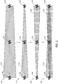
FIG. 2 is a flow diagram illustrating an example method of managing energy use in the network shown inFIG. 1 . -
FIG. 3 is a flow diagram illustrating an alternative method of managing energy use in the network shown inFIG. 1 . -
FIG. 4 is a schematic illustration of internal components of a drone that may be used in the network shown inFIG. 1 . -
FIG. 5 is a flow diagram illustrating an example method of operating a drone network. - Corresponding reference characters indicate corresponding parts throughout the drawings.
- Examples described below include systems and methods for efficiently managing energy use in a drone or drone network. As used herein, the term "drone" refers to an unmanned aerial vehicle that is either autonomous or remotely piloted. Drones in the network may be relatively small, bee-sized or handheld drones having a power consumption of about 10 Watts. The drones are typically spaced from each other as the "swarm" either remains stationary over a target location or travels to/from the target location. For example, a first drone at an outer edge of the swarm may be positioned a first distance from a second drone at an opposing outer edge of the swarm, and may be positioned a lesser second distance from a third drone interiorly located within the swarm. In one example, drones in the network use a laser communication system to facilitate high data rate communication with each other for coordinating drone movements and tasks, for example. As described herein, operation of the drones may be dynamically adjustable to conserve power when performing communication operations, and to store excess power derived from signals transmitted between drones in the network, or from signals received from ground-based systems.
- For example, systems and methods described facilitate transmitting signals between drones in the network, such as the first drone to the second, third and/or successive drones, in an energy efficient manner. In one example, the first drone has a transmitter subsystem that transmits a signal to at least the second drone. The first drone also has a receiver subsystem that receives a return signal from the second drone. The return signal contains data that enables the first drone to modulate its signal transmission power to a minimum signal power that is just high enough to be processed at the second drone. Accordingly, the first drone conserves energy and battery life by transmitting signals at the minimum signal power that is no greater than necessary for communicating with the second drone. However, the third drone is positioned the lesser second distance from the first drone such that the modulated signals are received at the third drone with excess signal power. Accordingly, the third drone includes an energy collection subsystem that collects and stores the excess signal power in the third drone. The drones may be repositioned relative to each other to facilitate balancing the power consumption load and the energy collection potential across the swarm. Thus, the drones work together to enhance the operational capabilities of the swarm, and to improve data transmission security by maintaining a broadcast area within the physical space defined by the swarm.
- As used herein, an element or step recited in the singular and preceded with the word "a" or "an" should be understood as not excluding plural elements or steps, unless such exclusion is explicitly recited. Furthermore, references to "example", "example implementation" or "one implementation" of the present disclosure are not intended to be interpreted as excluding the existence of additional implementations that also incorporate the recited features.
-
FIG. 1 is an illustration of anexample drone network 100. In the example implementation,network 100 includes a plurality ofdrones 102, defining aswarm 104, that can move independently of each other within or outside ofswarm 104, and/or that can be moved synchronously with each other in coordinated movements.Drones 102 are wirelessly communicatively coupled with each other to facilitate and coordinate the movement ofindividual drones 102 withinswarm 104. In addition, at least somedrones 102 may be spaced at different distances from each other withinswarm 104. For example,drones 102 may include afirst drone 106, asecond drone 108 spaced a first distance D1 fromfirst drone 106, and athird drone 110 spaced a lesser second distance D2 fromfirst drone 106 andsecond drone 108. -
First drone 106 andsecond drone 108 may be positioned at opposing peripheral edges ofswarm 104 such thatsecond drone 108 is the farthest positioneddrone 102 fromfirst drone 106 inswarm 104. To effectively communicate betweenfirst drone 106 andsecond drone 108, signals transmitted therebetween have a signal power greater than a threshold power level.Drones 102 positioned a lesser distance fromfirst drone 106 thansecond drone 108 may also be an intended or unintended recipient of the signals transmitted fromfirst drone 106 tosecond drone 108. However, due to the proximity of theother drones 102 tofirst drone 106, signals transmitted fromfirst drone 106 tosecond drone 108 may contain excess signal power when received at theother drones 102, such asthird drone 110. As will be described in more detail below, excess power contained in the signals may be collected and stored by theother drones 102 to enhance the operational service time ofswarm 104. -
FIG. 2 is a flow diagram illustrating an example method of managing energy use in network 100 (shown inFIG. 1 ). In the example implementation,first drone 106 emits afirst signal 112 therefrom for reception atsecond drone 108.Second drone 108 analyzesfirst signal 112 to determine a minimum signal power (i.e., the threshold power level) for signals emitted fromfirst drone 106 to be processed atsecond drone 108. For digital signals, the ability ofsecond drone 108 to process signals, and thus to determine the minimum signal power and potentially excess power in the signals, is based at least partially on an ability thesecond drone 108 to decipher bits of a bit stream that define the signals. For example, a processor (shown inFIG. 4 ) ofsecond drone 108 may analyze the signals to determine a bit error rate, and the bit error rate may be compared to a threshold value (i.e., a minimum signal bit error rate). If the determined bit error rate exceeds the threshold value, the minimum signal power is verified and excess signal power may be present. For analog signals, the ability ofsecond drone 108 to process signals is based at least partially on the spurious free dynamic range (SFDR) of the signals. For example, minimum signal power may be determined to be at the lower end of the SFDR, and excess signal power may be determined to be present at any power level greater than the lower end of the SFDR. - In one example,
first drone 106 emitsfirst signal 112 having a fading power level to facilitate determining the minimum signal power. For example, in afirst process step 114 illustrated inFIG. 2 ,first drone 106 emitsfirst signal 112 having a first signal power that is greater than the minimum power required forfirst signal 112 to be processed atsecond drone 108. Valuable power reserves infirst drone 106 may be depleted at an inefficient rate iffirst drone 106 continued to emitfirst signal 112 at the first signal power. In addition, emittingfirst signal 112 at a signal power greater than that is necessary to be processed atsecond drone 108 may carryfirst signal 112 outside ofnetwork 100 for reception by unsecure and unintended third party recipients. Accordingly, fromfirst process step 114 to asecond process step 116, the signal power offirst signal 112 is progressively reduced from the first signal power to a second signal power. In the example implementation, the fading power level offirst signal 112 is monitored atsecond drone 108, andsecond drone 108 analyzes the fading power level to determine the minimum signal power forfirst signal 112 to be processed atsecond drone 108. - In a
third process step 118,second drone 108 emits areturn signal 120 towardsfirst drone 106.Return signal 120 contains minimum signal power data, which providesfirst drone 106 with information on the power level for emittingfirst signal 112 towardssecond drone 108 that enablesfirst signal 112 to be processed atsecond drone 108.Return signal 120 may be emitted towardsfirst drone 106 at the minimum signal power.First drone 106 receivesreturn signal 120 and modulates the power of signals to be emitted towardssecond drone 108 based on the minimum signal power data. Accordingly, in afourth process step 122, effective and power-saving communication is established betweenfirst drone 106 andsecond drone 108. Specifically,first signals 112 and returnsignals 120 are transmitted betweenfirst drone 106 andsecond drone 108 at the minimum signal power to facilitate conserving the energy offirst drone 106 andsecond drone 108. - In the example implementation,
third drone 110 is positioned betweenfirst drone 106 andsecond drone 108 throughout the process steps 114, 116, 118, and 122. In operation,third drone 110 analyzesfirst signal 112 and return signal 120 to determine a minimum signal power for signals emitted fromfirst drone 106 andsecond drone 108 to be processed atthird drone 110. Becausethird drone 110 is positioned the lesser second distance D2 (shown inFIG. 1 ) fromfirst drone 106 andsecond drone 108, the minimum signal power for processingfirst signal 112 and return signal 120 atthird drone 110 is less than the minimum signal power for processingfirst signal 112 atsecond drone 108, for example. Accordingly,third drone 110 may determinefirst signal 112 and return signal 120 contain excess signal power when received atthird drone 110. The excess signal power may be determined based on a difference between the power offirst signal 112 and return signal 120 as received atthird drone 110, and the minimum signal power for processing the signals atthird drone 110. Accordingly,third drone 110 may collect and store the excess signal power to enhance its operational capabilities and service life. -
FIG. 3 is a flow diagram illustrating an alternative method of managing energy use in network 100 (shown inFIG. 1 ). As described above,second drone 108 analyzesfirst signal 112 emitted fromfirst drone 106 to determine a minimum signal power for signals emitted fromfirst drone 106 to be processed atsecond drone 108. In the example implementation,first drone 106 emitsfirst signal 112 having a fixed power level to facilitate determining the minimum signal power. For example, in afirst process step 124 illustrated inFIG. 3 ,first drone 106 emitsfirst signal 112 having a signal power that is greater than the minimum power required forfirst signal 112 to be processed atsecond drone 108.Second drone 108 then attenuates the power level offirst signal 112 by an attenuation value. The attenuation value is determined based on a difference between the minimum signal power and a power offirst signal 112 as received atsecond drone 108. In asecond process step 126,second drone 108 emits return signal 120 towardsfirst drone 106.Return signal 120 contains minimum signal power data including the attenuation value determined bysecond drone 108.First drone 106 receivesreturn signal 120 and modulates the power of signals to be emitted towardssecond drone 108 based on the minimum signal power data, such as modulating the power of the signals proportionally with the attenuation value. Accordingly, in athird process step 128, effective and power-saving communication is established betweenfirst drone 106 andsecond drone 108. Specifically,first signals 112 and returnsignals 120 are transmitted betweenfirst drone 106 andsecond drone 108 at the minimum signal power to facilitate conserving the energy offirst drone 106 andsecond drone 108. - In the examples illustrated in
FIGS. 2 and3 , the signal power emitted fromfirst drone 106 may also be increased to determine the minimum signal power if interference, for example, restricts the ability ofsecond drone 108 to process signal 112. - Referring again to
FIG. 1 ,drones 102 inswarm 104 can move independently of each other within or outside ofnetwork 100, and/or can be moved synchronously with each other in coordinated movements. For example, swarm 104 can be positioned at a fixed location relative to the earth asdrones 102 are moved relative to each other. Alternatively, swarm 104 can be moved at a velocity relative to the earth asdrones 102 are moved relative to each other. In either example, drones 102 may be moved relative to each other to facilitate balancing the power consumption load and the energy collection potential acrossswarm 104. - For example, in the swarm configuration illustrated in
FIG. 1 ,first drone 106 may have a greater power consumption load thanthird drone 110 as a result of the need forfirst drone 106 to use more power to effectively communicate withsecond drone 108 than withthird drone 110. As such,first drone 106 may be moved inward from its position at the peripheral edge ofswarm 104, thereby reducing a distance offirst drone 106 relative toother drones 102 inswarm 104 and reducing an amount of power for effectively communicating with the other drones 102. In one example,first drone 106 may be moved to a relative center ofswarm 104 after being positioned at the peripheral edge for a preset amount of time, or based on an analysis of remaining battery life offirst drone 106. - In another example,
first drone 106 andthird drone 110 may switch relative positions withinswarm 104 such thatthird drone 110 moved from the relative center ofswarm 104 to the peripheral edge ofswarm 104. During operation ofswarm 104 and up to the time of the position switching,third drone 110 has used less transmission power and has also collected power fromother drones 102. Accordingly, movingfirst drone 106 andthird drone 110 relative to each other also facilitates balancing the power consumption load and the energy collection potential acrossswarm 104. - While the above description has been discussed in the context of
drones drones 102 innetwork 100 simultaneously to facilitate managing energy conservation. -
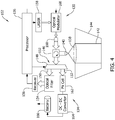
FIG. 4 is a schematic illustration of internal components of adrone 102 that may be used in network 100 (shown inFIG. 1 ). In the example implementation,drone 102 includes atransmitter subsystem 130, areceiver subsystem 132, anenergy collection subsystem 134, and aprocessor 136. Thesubsystems drone 102 includes acollection lens 138 and a culminatinglens 140 for emittingoutgoing signals 142, and for receivingincoming signals 144 fromother drones 102. - When in a first receiving mode,
incoming signals 144 are routed throughlenses circulator 146.Circulator 146 may be a free-space optical circulator or a fiber-basedcirculator 146.Circulator 146 is a passive multiport device that enables signals to be transmitted and received from the same component. Accordingly,incoming signals 144 received atcirculator 146 are routed towards atunable beam splitter 148, which is controlled byprocessor 136 to determine a splitting ratio to be executed bybeam splitter 148. In an alternative example,incoming signals 144 received atcirculator 146 are routed towards a tunable fiber coupler (not shown). In one example,processor 136controls beam splitter 148 to splitincoming signals 144 into afirst output 150 and asecond output 152.First output 150 is routed towardsprocessor 136, andsecond output 152 is routed towards components ofenergy collection subsystem 134, as will be described in more detail below. - In the example implementation,
first output 150 is routed through anoptical filter 154 and areceiver 156 that are positioned betweenbeam splitter 148 andprocessor 136.Optical filter 154 filters noise fromfirst output 150 ofincoming signals 144, and areceiver 156.Receiver 156 may be defined by a photodiode that converts an optical signal to an electronic signal, and a electrical filter that filters electrical noise from the signal.Processor 136 then analyzesfirst output 150 to determine a minimum signal power forincoming signals 144 to be processed atdrone 102.Transmitter subsystem 130 includes alaser emitter 158 in communication withprocessor 136, and acollimator 160 positioned betweenlaser emitter 158 andlenses processor 136controls laser emitter 158 to transmit an outgoing signal 142 (e.g., return signal 120) that contains minimum signal power data, as described above once, once the minimum signal power has been determined. In one embodiment,laser emitter 158 is a CW Nd3+:YAG emitter. - In an alternative example, a limited number of
drones 102 inswarm 104 have astandalone laser emitter 158 installed thereon, and the remainingdrones 102 have alaser emitter 158 that is a modulating retroreflector installed thereon. Accordingly, the limited number ofdrones 102, such as asingle drone 102, may be a source of laser transmissions, and the remainingdrones 102 conserve energy by reflecting signals received from the source. - When in the first receiving mode,
processor 136 also analyzesincoming signals 144 to determine the presence of excess signal power therein.Incoming signals 144 may be received fromother drones 102 inswarm 104, or may be received from ground-based systems. If it is determinedincoming signals 144 contain excess signal power,processor 136 may adjust the ratio ofbeam splitter 148 to enablesecond output 152 ofincoming signals 144 to be routed towardsenergy collection subsystem 134. In the example implementation,energy collection subsystem 134 includes a photovoltaic (PV)cell 162, a DC-DC (power)converter 164, and abattery 166 electrically connected to power-consuming components ofdrone 102. In operation,photovoltaic cell 162 converts the energy of incoming signals 144 (i.e., laser transmissions) to electricity, and DC-DC converter 164 further converts the electricity for storage withinbattery 166. Alternatively, the output of DC-DC converter may be routed directly to energy-consuming components ofdrone 102. - When in a second receiving mode,
drone 102 may be the recipient ofincoming signals 144 that contain minimum signal power data.Incoming signals 144 may be analyzed byprocessor 136, and the operation oftransmitter subsystem 130 adjusted accordingly to facilitate conservingbattery 166. In the example implementation,transmitter subsystem 130 includes anoptical modulator 168 that receives an output fromlaser emitter 158, and that selectively manipulates the output for generatingoutgoing signals 142. For example, ifprocessor 136 determinesoutgoing signals 142 are being transmitted at a power level that is greater than the minimum signal power,optical modulator 168 is operable to reduce the power level ofoutgoing signals 142 to the minimum signal power. -
FIG. 5 is a flow diagram illustrating anexample method 200 of operating a drone network.Method 200 includes emitting 202 a first signal from a first drone, receiving 204 the signal at a second drone in the network, determining 206, at the second drone, a minimum signal power for the signal to be processed at the second drone, emitting 208, from the second drone to the first drone, a return signal that contains minimum signal power data as determined at the second drone, and emitting 210 a second signal from the first drone to the second drone, wherein the power of the second signal is modulated based on the minimum signal power data. - Further, the disclosure comprises the following examples, whereby the scope of protection is provided by the claims.
- Example 1. A drone network comprising: a first drone comprising a first receiver, a first transmitter, and a first processor; and a second drone positionable at a distance from the first drone, the second drone comprising a second receiver, a second transmitter, and a second processor, wherein the first transmitter is configured to emit a signal towards the second drone for reception at the second receiver, and the second processor is configured to determine a minimum signal power for the signal to be processed at the second drone, wherein the second transmitter is configured to emit a return signal towards the first drone for reception at the first receiver, the return signal containing minimum signal power data as determined by the second processor, and the first processor is configured to modulate the power of signals to be emitted towards the second drone from the first transmitter based on the minimum signal power data.
- Example 2. The network in accordance with Claim 1, wherein the first transmitter is configured to emit the signal having a fading power level, and wherein the second processor is configured to monitor the fading power level to determine the minimum signal power.
- Example 3. The network in accordance with any of examples 1-2, wherein the first transmitter is configured to emit the signal having a fixed power level, and wherein the second processor is configured to generate the minimum signal power data based on an attenuation value that is determined based on a difference between a power of the signal and the minimum signal power.
- Example 4. The network in accordance with any of examples 1-3, wherein the first processor is configured to modulate the power of signals to be emitted towards the second drone to a power level approximately equal to the minimum signal power.
- Example 5. The network in accordance with any of examples 1-4, wherein the second processor is further configured to determine an excess signal power contained in the signal based on a difference between a power of the signal and the minimum signal power, the second drone further comprising an energy collection subsystem configured to collect and store the excess signal power within the second drone.
- Example 6. The network in accordance with any of examples 1-5 further comprising a third drone positionable a lesser distance from the first drone than the second drone, wherein the third drone comprises: a third receiver configured to receive the signal emitted by the first drone; a third processor configured to determine a minimum signal power for the signal to be processed at the third drone, and to determine an excess signal power contained in the signal based on a difference between a power of the signal and the minimum signal power; and an energy collection subsystem configured to collect and store the excess signal power within the third drone.
- Example 7. The network in accordance with example 6, wherein the third drone further comprises a third transmitter configured to emit a return signal towards the first drone for reception at the first receiver, the return signal containing minimum signal power data as determined by the third processor, wherein the first processor is configured to modulate the power of signals to be emitted towards the second and third drones from the first transmitter based on an analysis of the minimum signal power data contained in the return signals.
- Example 8. A drone comprising: a receiver subsystem configured to receive a signal; a processor configured to determine a minimum signal power for the signal to be processed at the drone, and configured to determine an excess signal power contained in the signal based on a difference between a power of the signal and the minimum signal power; and an energy collection subsystem configured to collect and store the excess signal power.
- Example 9. The drone in accordance with example 8 further comprising a transmitter subsystem comprising a laser emitter and an optical modulator both controllable by the processor, the laser emitter configured to provide an output towards the optical modulator, and the optical modulator configured to selectively modulate the power of the output to form a signal to be emitted from the drone.
- Example 10. The drone in accordance with example 9, wherein the processor is configured to identify if there is excess signal power in the signal, and is configured to modulate, with the optical modulator, the power of the emitted signal when the excess signal power is identified.
- Example 11. The drone in accordance with any of examples 9-10, wherein the laser emitter comprises a modulating retroreflector.
- Example 12. The drone in accordance with any of examples 9-11 further comprising a circulator configured to selectively route inputs and outputs between the receiver subsystem and the transmitter subsystem.
- Example 13. The drone in accordance with example 8 further comprising a transmitter subsystem configured to emit a return signal from the drone, the return signal containing minimum signal power data as determined by the processor.
- Example 14. The drone in accordance with example 8, wherein the receiver subsystem comprises a beam splitter controllable by the processor, and wherein the energy collection subsystem comprises a battery, wherein the processor is configured to identify if there is excess signal power in the signal based on a first output received from the beam splitter, and, when the excess signal power is identified, is configured to direct the beam splitter to provide a second output, containing the excess signal power, to the battery.
- Example 15. The drone in accordance with example 14, wherein the energy collection subsystem further comprises a photovoltaic cell and a power converter coupled between the beam splitter and the battery for converting the second output to storable power.
- Example 16. A method of controlling operation of a drone network, the method comprising: emitting a first signal from a first drone; receiving the signal at a second drone in the network; determining, at the second drone, a minimum signal power for the signal to be processed at the second drone; emitting, from the second drone to the first drone, a return signal that contains minimum signal power data as determined at the second drone; and emitting a second signal from the first drone to the second drone, wherein the power of the second signal is modulated based on the minimum signal power data.
- Example 17. The method in accordance with example 16 further comprising: receiving the signal at a third drone in the network, wherein the third drone is positionable a lesser distance from the first drone than the second drone; storing, at the third drone, excess signal power contained in the signal emitted from the first drone; selectively moving the first, second, and third drones relative to each other to position the second drone a lesser distance from the first drone than the third drone; and storing, at the second drone, excess signal power contained in the signal emitted from the first drone.
- Example 18. The method in accordance with example 17, wherein the first, second, and third drones define a drone swarm, the method further comprising positioning the drone swarm at a fixed location relative to the earth as the first, second, and third drones are moved relative to each other.
- Example 19. The method in accordance with any of examples 17-18, wherein the first, second, and third drones define a drone swarm, the method further comprising moving the drone swarm at a velocity relative to the earth as the first, second, and third drones are moved relative to each other.
- Example 20. The method in accordance with any of examples 17-19, wherein a plurality of drones, including at least the first and second drones, define a drone swarm, the method further comprising moving the first drone to a relative center of the drone swarm.
- This written description uses examples to disclose various implementations, including the best mode, and also to enable any person skilled in the art to practice the various implementations, including making and using any devices or systems and performing any incorporated methods. The patentable scope of the disclosure is defined by the claims, and may include other examples that occur to those skilled in the art after reading this specification. Such other examples are intended to be within the scope of the claims if they have structural elements that do not differ from the literal language of the claims, or if they include equivalent structural elements with insubstantial differences from the literal language of the claims.
Claims (15)
- A drone network (100) comprising:a first drone (106) comprising a first receiver (132), a first transmitter (130), and a first processor (136); anda second drone (108) positionable a distance from the first drone (106), the second drone (108) comprising a second receiver (132), a second transmitter (130), and a second processor (136), wherein the first transmitter (130) is configured to emit a signal (112) towards the second drone (108) for reception at the second receiver (132), and the second processor (136) is configured to determine a minimum signal power for the signal (112) to be processed at the second drone (108), wherein the second transmitter (130) is configured to emit a return signal (120) towards the first drone (106) for reception at the first receiver (132), the return signal (120) containing minimum signal power data as determined by the second processor (136), and the first processor (136) is configured to modulate the power of signals (112) to be emitted towards the second drone (108) from the first transmitter (130) based on the minimum signal power data.
- The network (100) in accordance with Claim 1, wherein the first transmitter (130) is configured to emit the signal (112) having a fading power level, and wherein the second processor (136) is configured to monitor the fading power level to determine the minimum signal power.
- The network (100) in accordance with any of Claims 1-2, wherein the first transmitter (130) is configured to emit the signal (112) having a fixed power level, and wherein the second processor (136) is configured to generate the minimum signal power data based on an attenuation value that is determined based on a difference between a power of the signal (112) and the minimum signal power.
- The network (100) in accordance with any of Claims 1-3, wherein the first processor (136) is configured to modulate the power of signals (112) to be emitted towards the second drone (108) to a power level approximately equal to the minimum signal power.
- The network (100) in accordance with any of Claims 1-4, wherein the second processor (136) is further configured to determine an excess signal power contained in the signal based on a difference between a power of the signal (112) and the minimum signal power, the second drone (108) further comprising an energy collection subsystem (134) configured to collect and store the excess signal power within the second drone (108).
- The network (100) in accordance with any of Claims 1-5 further comprising a third drone (110) positionable a lesser distance from the first drone (106) than the second drone (108), wherein the third drone (110) comprises:a third receiver (132) configured to receive the signal (112) emitted by the first drone (106);a third processor (136) configured to determine a minimum signal power for the signal (112) to be processed at the third drone (110), and to determine an excess signal power contained in the signal (112) based on a difference between a power of the signal (112) and the minimum signal power; andan energy collection subsystem (134) configured to collect and store the excess signal power within the third drone (110).
- The network (100) in accordance with Claim 6, wherein the third drone (110) further comprises a third transmitter (130) configured to emit a return signal (120) towards the first drone (106) for reception at the first receiver (132), the return signal (120) containing minimum signal power data as determined by the third processor (136), wherein the first processor (136) is configured to modulate the power of signals (112) to be emitted towards the second and third drone (110)s from the first transmitter (130) based on an analysis of the minimum signal power data contained in the return signal (120)s.
- The drone network (100) of Claim 1, wherein each of the plurality of drones (106, 108, 110) comprises:a receiver subsystem (132) configured to receive a signal (144);a processor (136) configured to determine a minimum signal power for the signal (144) to be processed at the drone (102), and configured to determine an excess signal power contained in the signal (144) based on a difference between a power of the signal (144) and the minimum signal power; andan energy collection subsystem (134) configured to collect and store the excess signal power.
- The drone network (100) in accordance with Claim 8, wherein each drone (106, 108, 110) further comprises a transmitter subsystem (130) comprising a laser emitter (158) and an optical modulator (168) both controllable by the processor (136), the laser emitter (158) configured to provide an output towards the optical modulator (168), and the optical modulator (168) configured to selectively modulate the power of the output to form a signal (142) to be emitted from each drone (106, 108, 110).
- The drone network (100) in accordance with Claim 9, wherein at least one of:the processor (136) is configured to identify if there is excess signal power in the signal (144), and is configured to modulate, with the optical modulator (168), the power of the emitted signal (142) when the excess signal power is identified;the laser emitter (158) comprises a modulating retroreflector; anda circulator (146) configured to selectively route inputs and outputs between the receiver subsystem (132) and the transmitter subsystem (130).
- A method of controlling operation of a drone network (100), the method comprising:emitting a first signal (112) from a first drone (106);receiving the first signal (112) at a second drone (108) in the network (100) ;determining, at the second drone (108), a minimum signal power for the first signal (112) to be processed at the second drone (108);emitting, from the second drone (108) to the first drone (106), a return signal (120) that contains minimum signal power data as determined at the second drone (108); andemitting a second signal (112) from the first drone (106) to the second drone (108), wherein the power of the second signal (112) is modulated based on the minimum signal power data.
- The method in accordance with Claim 11 further comprising:receiving the signal (112) at a third drone (110) in the network (100), wherein the third drone (110) is positionable a lesser distance from the first drone (106) than the second drone (108);storing, at the third drone (110), excess signal power contained in the signal (112) emitted from the first drone (106);selectively moving the first, second, and third drones (106, 108, 110) relative to each other to position the second drone (108) a lesser distance from the first drone (106) than the third drone (110); andstoring, at the second drone (108), excess signal power contained in the signal (112) emitted from the first drone (106).
- The method in accordance with Claim 12, wherein the first, second, and third drones (106, 108, 110) define a drone swarm (104), the method further comprising positioning the drone swarm (104) at a fixed location relative to the earth as the first, second, and third drones (106, 108, 110) are moved relative to each other.
- The method in accordance with any of Claims 12-13, wherein the first, second, and third drones (106, 108, 110) define a drone swarm (104), the method further comprising moving the drone swarm (104) at a velocity relative to the earth as the first, second, and third drones (106, 108, 110) are moved relative to each other.
- The method in accordance with any of Claims 12-14, wherein a plurality of drones, including at least the first and second drones (106, 108, 110), define a drone swarm (104), the method further comprising moving the first drone (106) to a relative center of the drone swarm (104).
Applications Claiming Priority (1)
| Application Number | Priority Date | Filing Date | Title |
|---|---|---|---|
| US16/745,438 US11165506B2 (en) | 2020-01-17 | 2020-01-17 | Drone network and method of operating |
Publications (2)
| Publication Number | Publication Date |
|---|---|
| EP3851931A1 true EP3851931A1 (en) | 2021-07-21 |
| EP3851931B1 EP3851931B1 (en) | 2023-02-01 |
Family
ID=73698672
Family Applications (1)
| Application Number | Title | Priority Date | Filing Date |
|---|---|---|---|
| EP20211610.9A Active EP3851931B1 (en) | 2020-01-17 | 2020-12-03 | Drone network and method of operating |
Country Status (4)
| Country | Link |
|---|---|
| US (1) | US11165506B2 (en) |
| EP (1) | EP3851931B1 (en) |
| JP (1) | JP7652569B2 (en) |
| CN (1) | CN113225799B (en) |
Families Citing this family (3)
| Publication number | Priority date | Publication date | Assignee | Title |
|---|---|---|---|---|
| US11862989B2 (en) * | 2021-03-26 | 2024-01-02 | International Business Machines Corporation Armonk | Environment driven solar power management |
| EP4227853B1 (en) * | 2022-02-09 | 2025-07-23 | Mitsubishi Electric R&D Centre Europe BV | User equipment for implementing a control in a set of user equipments |
| US12030677B2 (en) | 2022-07-26 | 2024-07-09 | The Boeing Company | Anomaly detection via self-lifting detector attachment member of unmanned aerial drone |
Citations (3)
| Publication number | Priority date | Publication date | Assignee | Title |
|---|---|---|---|---|
| US20030060171A1 (en) * | 2001-05-02 | 2003-03-27 | John Lovberg | Millimeter-wave communications link with adaptive transmitter power control |
| US20060018661A1 (en) * | 2002-03-04 | 2006-01-26 | Green Edward A | Alignment system |
| US20140376914A1 (en) * | 2013-06-25 | 2014-12-25 | Raytheon Company | Free-space optical mesh network |
Family Cites Families (38)
| Publication number | Priority date | Publication date | Assignee | Title |
|---|---|---|---|---|
| US4995101A (en) * | 1989-09-19 | 1991-02-19 | Gte Government Systems Corporation | Secure two-way communications with submerged submarines |
| US5528409A (en) * | 1994-10-13 | 1996-06-18 | Nt International, Inc. | Fiber-optic interface system |
| US6043920A (en) * | 1997-08-04 | 2000-03-28 | Motorola, Inc. | Method and apparatus for laser communication through a lossy medium |
| US6285481B1 (en) * | 1997-09-05 | 2001-09-04 | Trex Communications Corporation | Free-space laser communications error control system |
| US6141763A (en) * | 1998-09-01 | 2000-10-31 | Hewlett-Packard Company | Self-powered network access point |
| US6504634B1 (en) * | 1998-10-27 | 2003-01-07 | Air Fiber, Inc. | System and method for improved pointing accuracy |
| US6643467B1 (en) * | 2000-10-05 | 2003-11-04 | Lucent Technologies Inc. | Method and apparatus for controlling received power levels within a free space optical communication system |
| US7224908B2 (en) * | 2000-10-13 | 2007-05-29 | Kiribati Wireless Ventures, Llc | Attenuation and calibration systems and methods for use with a laser detector in an optical communication system |
| US20030090765A1 (en) * | 2001-11-09 | 2003-05-15 | Neff Brian W. | Free-space optical communication system |
| US7286766B2 (en) * | 2003-01-16 | 2007-10-23 | Aoptix Technologies, Inc. | Free space optical communication system with power level management |
| US20050238357A1 (en) * | 2004-04-27 | 2005-10-27 | Farrell Thomas C | Laser communication system with adaptive data rates |
| JP2005333188A (en) * | 2004-05-18 | 2005-12-02 | Konica Minolta Photo Imaging Inc | Communication method and communication apparatus |
| US20070003280A1 (en) * | 2005-04-15 | 2007-01-04 | Sada Gilberto I | Method and system for determining receiver power for required bit error rate |
| US7539882B2 (en) * | 2005-05-30 | 2009-05-26 | Rambus Inc. | Self-powered devices and methods |
| KR100866183B1 (en) * | 2007-01-08 | 2008-10-30 | 삼성전자주식회사 | Power initial value setting method using indicator light in visible light communication and transmitting and receiving device using same |
| CN101309097A (en) * | 2008-05-23 | 2008-11-19 | 深圳先进技术研究院 | Method and apparatus for implementing power control and method for managing neighbor list |
| US20100133436A1 (en) * | 2008-12-01 | 2010-06-03 | Plantronics, Inc. | Infrared Power Control Supporting Multi-Use Functionality |
| US8788119B2 (en) | 2010-12-09 | 2014-07-22 | The Boeing Company | Unmanned vehicle and system |
| US9819399B2 (en) * | 2011-05-27 | 2017-11-14 | uBeam Inc. | Beam interaction control for wireless power transfer |
| US9806768B2 (en) * | 2012-07-19 | 2017-10-31 | Samsung Electronics Co., Ltd. | Methods and device for controlling power transmission using NFC |
| US9680565B2 (en) * | 2013-03-15 | 2017-06-13 | Raytheon Company | Free-space optical network with agile beam-based protection switching |
| US9369008B2 (en) * | 2013-03-20 | 2016-06-14 | Nokia Technologies Oy | Method, apparatus, and computer program product for powering electronic devices |
| US9467953B2 (en) * | 2013-07-08 | 2016-10-11 | Netgear, Inc. | Systems and methods for wireless link balancing in wireless networks |
| US10038497B2 (en) * | 2013-12-18 | 2018-07-31 | Northrup Grumman Systems Corporation | Optical transceiver with variable data rate and sensitivity control |
| CN105072676B (en) | 2015-08-10 | 2018-12-18 | 重庆大学 | Aeronautical Ad hoc networks Poewr control method based on TDMA agreement |
| US10027181B2 (en) * | 2015-09-29 | 2018-07-17 | X-Celeprint Limited | Layers of safety and failsafe capability for operation of class IV laser in consumer electronics devices |
| US10454576B2 (en) * | 2015-12-31 | 2019-10-22 | Wellen Sham | UAV network |
| US9734684B2 (en) | 2016-01-04 | 2017-08-15 | International Business Machines Corporation | Perimeter monitoring using autonomous drones |
| WO2017177038A1 (en) * | 2016-04-06 | 2017-10-12 | Oakley Imani R | Method and system for autonomous and random drone travel |
| CN107479568A (en) * | 2016-06-08 | 2017-12-15 | 松下电器(美国)知识产权公司 | Unmanned vehicle, control method and control program |
| US10418856B2 (en) * | 2016-11-16 | 2019-09-17 | X Development Llc | Systems and methods for wireless charging |
| CN106604399A (en) * | 2016-12-29 | 2017-04-26 | 深圳天珑无线科技有限公司 | Energy collecting method and device |
| US10009119B1 (en) * | 2017-03-06 | 2018-06-26 | The Boeing Company | Bandgap modulation for underwater communications and energy harvesting |
| CN107132854A (en) * | 2017-04-28 | 2017-09-05 | 深圳市三合信义科技发展有限公司 | A kind of unmanned plane, unmanned plane control method and system based on white frequency spectrum |
| CN108254763B (en) * | 2017-12-29 | 2021-06-08 | 中国电子科技集团公司第二十研究所 | A method for remote detection and disposal of commercial small unmanned aerial vehicles |
| US10411797B1 (en) * | 2018-06-08 | 2019-09-10 | SA Photonics, Inc. | Free space optical node with fiber bundle |
| US10742329B2 (en) * | 2018-08-22 | 2020-08-11 | The Boeing Company | Drone enabled global communications system for underwater platforms |
| CN110391849A (en) * | 2019-07-25 | 2019-10-29 | 广东工业大学 | Communication system, unmanned aerial vehicle, communication method and device based on unmanned aerial vehicle |
-
2020
- 2020-01-17 US US16/745,438 patent/US11165506B2/en active Active
- 2020-12-03 EP EP20211610.9A patent/EP3851931B1/en active Active
-
2021
- 2021-01-07 CN CN202110018359.1A patent/CN113225799B/en active Active
- 2021-01-07 JP JP2021001233A patent/JP7652569B2/en active Active
Patent Citations (3)
| Publication number | Priority date | Publication date | Assignee | Title |
|---|---|---|---|---|
| US20030060171A1 (en) * | 2001-05-02 | 2003-03-27 | John Lovberg | Millimeter-wave communications link with adaptive transmitter power control |
| US20060018661A1 (en) * | 2002-03-04 | 2006-01-26 | Green Edward A | Alignment system |
| US20140376914A1 (en) * | 2013-06-25 | 2014-12-25 | Raytheon Company | Free-space optical mesh network |
Also Published As
| Publication number | Publication date |
|---|---|
| US11165506B2 (en) | 2021-11-02 |
| JP7652569B2 (en) | 2025-03-27 |
| CN113225799B (en) | 2025-10-03 |
| EP3851931B1 (en) | 2023-02-01 |
| US20210226708A1 (en) | 2021-07-22 |
| CN113225799A (en) | 2021-08-06 |
| JP2021119656A (en) | 2021-08-12 |
Similar Documents
| Publication | Publication Date | Title |
|---|---|---|
| EP3851931A1 (en) | Drone network and method of operating | |
| US10454576B2 (en) | UAV network | |
| US6115580A (en) | Communications network having adaptive network link optimization using wireless terrain awareness and method for use therein | |
| GB2542491A (en) | Apparatus and method for communications management | |
| CN110730028B (en) | Unmanned aerial vehicle-assisted backscatter communication device and resource allocation control method | |
| EP4568364A1 (en) | Transmit power | |
| Abou-Rjeily et al. | Free space optical cooperative communications via an energy harvesting harvest-store-use relay | |
| Bashir et al. | Energy optimization of a laser-powered hovering-UAV relay in optical wireless backhaul | |
| Biswas et al. | Deep-space optical terminals (DOT) systems engineering | |
| EP3335334B1 (en) | Apparatus and method for communications management | |
| CA2307382C (en) | Wireless data communications network and method for operating the data communications network | |
| WO2019204997A1 (en) | Autonomous mobile platform, control end and autonomous mobile platform system | |
| EP3335333B1 (en) | Apparatus and method for communications management | |
| CN116915316B (en) | Maritime mobile network wide-area coverage system based on UAV communication | |
| Kamatchi et al. | SLIPT enabled ground-to-UAV FSO communication for SAGNET in 6G-IoT systems | |
| CN120343657A (en) | A multi-mode satellite communication-Ascend computing power integrated module and data processing method | |
| US11490310B2 (en) | Communication method, electronic device, and communication system | |
| EP4258564A1 (en) | Method and device for adapting learning class-based system to ai mimo | |
| EP4598153A1 (en) | Maximum power reduction | |
| US20210136700A1 (en) | Dynamic optimization of transmitter power output (tpo) in portable wireless devices | |
| CN111796604A (en) | Light-load type remote cruise unmanned aerial vehicle group system | |
| Li et al. | An Integrated Optical Mobile Communication and Sensing System for Hovering UAVs | |
| Abdelhady et al. | Operation optimization of laser-powered aerial data harvesting for passive IoT networks | |
| CN109597428B (en) | Unmanned aerial vehicle anti-collision method based on ZigBee network, unmanned aerial vehicle and server | |
| Zuo et al. | A design for emergency communication based on wireless laser communication |
Legal Events
| Date | Code | Title | Description |
|---|---|---|---|
| PUAI | Public reference made under article 153(3) epc to a published international application that has entered the european phase |
Free format text: ORIGINAL CODE: 0009012 |
|
| STAA | Information on the status of an ep patent application or granted ep patent |
Free format text: STATUS: THE APPLICATION HAS BEEN PUBLISHED |
|
| AK | Designated contracting states |
Kind code of ref document: A1 Designated state(s): AL AT BE BG CH CY CZ DE DK EE ES FI FR GB GR HR HU IE IS IT LI LT LU LV MC MK MT NL NO PL PT RO RS SE SI SK SM TR |
|
| STAA | Information on the status of an ep patent application or granted ep patent |
Free format text: STATUS: REQUEST FOR EXAMINATION WAS MADE |
|
| 17P | Request for examination filed |
Effective date: 20220114 |
|
| RBV | Designated contracting states (corrected) |
Designated state(s): AL AT BE BG CH CY CZ DE DK EE ES FI FR GB GR HR HU IE IS IT LI LT LU LV MC MK MT NL NO PL PT RO RS SE SI SK SM TR |
|
| RIC1 | Information provided on ipc code assigned before grant |
Ipc: G05D 1/00 20060101ALI20220328BHEP Ipc: H04B 10/112 20130101ALI20220328BHEP Ipc: H04W 4/46 20180101ALI20220328BHEP Ipc: H04W 4/02 20180101ALI20220328BHEP Ipc: G05D 1/10 20060101AFI20220328BHEP |
|
| GRAP | Despatch of communication of intention to grant a patent |
Free format text: ORIGINAL CODE: EPIDOSNIGR1 |
|
| STAA | Information on the status of an ep patent application or granted ep patent |
Free format text: STATUS: GRANT OF PATENT IS INTENDED |
|
| INTG | Intention to grant announced |
Effective date: 20220831 |
|
| RIN1 | Information on inventor provided before grant (corrected) |
Inventor name: HILLER, NATHAN D. |
|
| GRAS | Grant fee paid |
Free format text: ORIGINAL CODE: EPIDOSNIGR3 |
|
| GRAA | (expected) grant |
Free format text: ORIGINAL CODE: 0009210 |
|
| STAA | Information on the status of an ep patent application or granted ep patent |
Free format text: STATUS: THE PATENT HAS BEEN GRANTED |
|
| AK | Designated contracting states |
Kind code of ref document: B1 Designated state(s): AL AT BE BG CH CY CZ DE DK EE ES FI FR GB GR HR HU IE IS IT LI LT LU LV MC MK MT NL NO PL PT RO RS SE SI SK SM TR |
|
| REG | Reference to a national code |
Ref country code: GB Ref legal event code: FG4D |
|
| REG | Reference to a national code |
Ref country code: CH Ref legal event code: EP Ref country code: AT Ref legal event code: REF Ref document number: 1547085 Country of ref document: AT Kind code of ref document: T Effective date: 20230215 |
|
| REG | Reference to a national code |
Ref country code: DE Ref legal event code: R096 Ref document number: 602020007916 Country of ref document: DE |
|
| REG | Reference to a national code |
Ref country code: IE Ref legal event code: FG4D |
|
| RAP4 | Party data changed (patent owner data changed or rights of a patent transferred) |
Owner name: THE BOEING COMPANY |
|
| REG | Reference to a national code |
Ref country code: LT Ref legal event code: MG9D |
|
| REG | Reference to a national code |
Ref country code: NL Ref legal event code: MP Effective date: 20230201 |
|
| P01 | Opt-out of the competence of the unified patent court (upc) registered |
Effective date: 20230516 |
|
| REG | Reference to a national code |
Ref country code: AT Ref legal event code: MK05 Ref document number: 1547085 Country of ref document: AT Kind code of ref document: T Effective date: 20230201 |
|
| PG25 | Lapsed in a contracting state [announced via postgrant information from national office to epo] |
Ref country code: RS Free format text: LAPSE BECAUSE OF FAILURE TO SUBMIT A TRANSLATION OF THE DESCRIPTION OR TO PAY THE FEE WITHIN THE PRESCRIBED TIME-LIMIT Effective date: 20230201 Ref country code: PT Free format text: LAPSE BECAUSE OF FAILURE TO SUBMIT A TRANSLATION OF THE DESCRIPTION OR TO PAY THE FEE WITHIN THE PRESCRIBED TIME-LIMIT Effective date: 20230601 Ref country code: NO Free format text: LAPSE BECAUSE OF FAILURE TO SUBMIT A TRANSLATION OF THE DESCRIPTION OR TO PAY THE FEE WITHIN THE PRESCRIBED TIME-LIMIT Effective date: 20230501 Ref country code: NL Free format text: LAPSE BECAUSE OF FAILURE TO SUBMIT A TRANSLATION OF THE DESCRIPTION OR TO PAY THE FEE WITHIN THE PRESCRIBED TIME-LIMIT Effective date: 20230201 Ref country code: LV Free format text: LAPSE BECAUSE OF FAILURE TO SUBMIT A TRANSLATION OF THE DESCRIPTION OR TO PAY THE FEE WITHIN THE PRESCRIBED TIME-LIMIT Effective date: 20230201 Ref country code: LT Free format text: LAPSE BECAUSE OF FAILURE TO SUBMIT A TRANSLATION OF THE DESCRIPTION OR TO PAY THE FEE WITHIN THE PRESCRIBED TIME-LIMIT Effective date: 20230201 Ref country code: HR Free format text: LAPSE BECAUSE OF FAILURE TO SUBMIT A TRANSLATION OF THE DESCRIPTION OR TO PAY THE FEE WITHIN THE PRESCRIBED TIME-LIMIT Effective date: 20230201 Ref country code: ES Free format text: LAPSE BECAUSE OF FAILURE TO SUBMIT A TRANSLATION OF THE DESCRIPTION OR TO PAY THE FEE WITHIN THE PRESCRIBED TIME-LIMIT Effective date: 20230201 Ref country code: AT Free format text: LAPSE BECAUSE OF FAILURE TO SUBMIT A TRANSLATION OF THE DESCRIPTION OR TO PAY THE FEE WITHIN THE PRESCRIBED TIME-LIMIT Effective date: 20230201 |
|
| PG25 | Lapsed in a contracting state [announced via postgrant information from national office to epo] |
Ref country code: SE Free format text: LAPSE BECAUSE OF FAILURE TO SUBMIT A TRANSLATION OF THE DESCRIPTION OR TO PAY THE FEE WITHIN THE PRESCRIBED TIME-LIMIT Effective date: 20230201 Ref country code: PL Free format text: LAPSE BECAUSE OF FAILURE TO SUBMIT A TRANSLATION OF THE DESCRIPTION OR TO PAY THE FEE WITHIN THE PRESCRIBED TIME-LIMIT Effective date: 20230201 Ref country code: IS Free format text: LAPSE BECAUSE OF FAILURE TO SUBMIT A TRANSLATION OF THE DESCRIPTION OR TO PAY THE FEE WITHIN THE PRESCRIBED TIME-LIMIT Effective date: 20230601 Ref country code: GR Free format text: LAPSE BECAUSE OF FAILURE TO SUBMIT A TRANSLATION OF THE DESCRIPTION OR TO PAY THE FEE WITHIN THE PRESCRIBED TIME-LIMIT Effective date: 20230502 Ref country code: FI Free format text: LAPSE BECAUSE OF FAILURE TO SUBMIT A TRANSLATION OF THE DESCRIPTION OR TO PAY THE FEE WITHIN THE PRESCRIBED TIME-LIMIT Effective date: 20230201 |
|
| PG25 | Lapsed in a contracting state [announced via postgrant information from national office to epo] |
Ref country code: SM Free format text: LAPSE BECAUSE OF FAILURE TO SUBMIT A TRANSLATION OF THE DESCRIPTION OR TO PAY THE FEE WITHIN THE PRESCRIBED TIME-LIMIT Effective date: 20230201 Ref country code: RO Free format text: LAPSE BECAUSE OF FAILURE TO SUBMIT A TRANSLATION OF THE DESCRIPTION OR TO PAY THE FEE WITHIN THE PRESCRIBED TIME-LIMIT Effective date: 20230201 Ref country code: EE Free format text: LAPSE BECAUSE OF FAILURE TO SUBMIT A TRANSLATION OF THE DESCRIPTION OR TO PAY THE FEE WITHIN THE PRESCRIBED TIME-LIMIT Effective date: 20230201 Ref country code: DK Free format text: LAPSE BECAUSE OF FAILURE TO SUBMIT A TRANSLATION OF THE DESCRIPTION OR TO PAY THE FEE WITHIN THE PRESCRIBED TIME-LIMIT Effective date: 20230201 Ref country code: CZ Free format text: LAPSE BECAUSE OF FAILURE TO SUBMIT A TRANSLATION OF THE DESCRIPTION OR TO PAY THE FEE WITHIN THE PRESCRIBED TIME-LIMIT Effective date: 20230201 |
|
| REG | Reference to a national code |
Ref country code: DE Ref legal event code: R097 Ref document number: 602020007916 Country of ref document: DE |
|
| REG | Reference to a national code |
Ref country code: DE Ref legal event code: R079 Ref document number: 602020007916 Country of ref document: DE Free format text: PREVIOUS MAIN CLASS: G05D0001100000 Ipc: G05D0001460000 |
|
| PG25 | Lapsed in a contracting state [announced via postgrant information from national office to epo] |
Ref country code: SK Free format text: LAPSE BECAUSE OF FAILURE TO SUBMIT A TRANSLATION OF THE DESCRIPTION OR TO PAY THE FEE WITHIN THE PRESCRIBED TIME-LIMIT Effective date: 20230201 |
|
| PLBE | No opposition filed within time limit |
Free format text: ORIGINAL CODE: 0009261 |
|
| STAA | Information on the status of an ep patent application or granted ep patent |
Free format text: STATUS: NO OPPOSITION FILED WITHIN TIME LIMIT |
|
| 26N | No opposition filed |
Effective date: 20231103 |
|
| PG25 | Lapsed in a contracting state [announced via postgrant information from national office to epo] |
Ref country code: SI Free format text: LAPSE BECAUSE OF FAILURE TO SUBMIT A TRANSLATION OF THE DESCRIPTION OR TO PAY THE FEE WITHIN THE PRESCRIBED TIME-LIMIT Effective date: 20230201 |
|
| PG25 | Lapsed in a contracting state [announced via postgrant information from national office to epo] |
Ref country code: IT Free format text: LAPSE BECAUSE OF FAILURE TO SUBMIT A TRANSLATION OF THE DESCRIPTION OR TO PAY THE FEE WITHIN THE PRESCRIBED TIME-LIMIT Effective date: 20230201 |
|
| REG | Reference to a national code |
Ref country code: CH Ref legal event code: PL |
|
| PG25 | Lapsed in a contracting state [announced via postgrant information from national office to epo] |
Ref country code: LU Free format text: LAPSE BECAUSE OF NON-PAYMENT OF DUE FEES Effective date: 20231203 |
|
| PG25 | Lapsed in a contracting state [announced via postgrant information from national office to epo] |
Ref country code: MC Free format text: LAPSE BECAUSE OF FAILURE TO SUBMIT A TRANSLATION OF THE DESCRIPTION OR TO PAY THE FEE WITHIN THE PRESCRIBED TIME-LIMIT Effective date: 20230201 |
|
| REG | Reference to a national code |
Ref country code: BE Ref legal event code: MM Effective date: 20231231 |
|
| PG25 | Lapsed in a contracting state [announced via postgrant information from national office to epo] |
Ref country code: MC Free format text: LAPSE BECAUSE OF FAILURE TO SUBMIT A TRANSLATION OF THE DESCRIPTION OR TO PAY THE FEE WITHIN THE PRESCRIBED TIME-LIMIT Effective date: 20230201 Ref country code: LU Free format text: LAPSE BECAUSE OF NON-PAYMENT OF DUE FEES Effective date: 20231203 |
|
| REG | Reference to a national code |
Ref country code: IE Ref legal event code: MM4A |
|
| PG25 | Lapsed in a contracting state [announced via postgrant information from national office to epo] |
Ref country code: IE Free format text: LAPSE BECAUSE OF NON-PAYMENT OF DUE FEES Effective date: 20231203 |
|
| PG25 | Lapsed in a contracting state [announced via postgrant information from national office to epo] |
Ref country code: BE Free format text: LAPSE BECAUSE OF NON-PAYMENT OF DUE FEES Effective date: 20231231 |
|
| PG25 | Lapsed in a contracting state [announced via postgrant information from national office to epo] |
Ref country code: CH Free format text: LAPSE BECAUSE OF NON-PAYMENT OF DUE FEES Effective date: 20231231 |
|
| PG25 | Lapsed in a contracting state [announced via postgrant information from national office to epo] |
Ref country code: IE Free format text: LAPSE BECAUSE OF NON-PAYMENT OF DUE FEES Effective date: 20231203 Ref country code: CH Free format text: LAPSE BECAUSE OF NON-PAYMENT OF DUE FEES Effective date: 20231231 Ref country code: BE Free format text: LAPSE BECAUSE OF NON-PAYMENT OF DUE FEES Effective date: 20231231 |
|
| PG25 | Lapsed in a contracting state [announced via postgrant information from national office to epo] |
Ref country code: BG Free format text: LAPSE BECAUSE OF FAILURE TO SUBMIT A TRANSLATION OF THE DESCRIPTION OR TO PAY THE FEE WITHIN THE PRESCRIBED TIME-LIMIT Effective date: 20230201 |
|
| PG25 | Lapsed in a contracting state [announced via postgrant information from national office to epo] |
Ref country code: BG Free format text: LAPSE BECAUSE OF FAILURE TO SUBMIT A TRANSLATION OF THE DESCRIPTION OR TO PAY THE FEE WITHIN THE PRESCRIBED TIME-LIMIT Effective date: 20230201 |
|
| PG25 | Lapsed in a contracting state [announced via postgrant information from national office to epo] |
Ref country code: CY Free format text: LAPSE BECAUSE OF FAILURE TO SUBMIT A TRANSLATION OF THE DESCRIPTION OR TO PAY THE FEE WITHIN THE PRESCRIBED TIME-LIMIT; INVALID AB INITIO Effective date: 20201203 |
|
| PG25 | Lapsed in a contracting state [announced via postgrant information from national office to epo] |
Ref country code: HU Free format text: LAPSE BECAUSE OF FAILURE TO SUBMIT A TRANSLATION OF THE DESCRIPTION OR TO PAY THE FEE WITHIN THE PRESCRIBED TIME-LIMIT; INVALID AB INITIO Effective date: 20201203 |
|
| PG25 | Lapsed in a contracting state [announced via postgrant information from national office to epo] |
Ref country code: TR Free format text: LAPSE BECAUSE OF FAILURE TO SUBMIT A TRANSLATION OF THE DESCRIPTION OR TO PAY THE FEE WITHIN THE PRESCRIBED TIME-LIMIT Effective date: 20230201 |
|
| PGFP | Annual fee paid to national office [announced via postgrant information from national office to epo] |
Ref country code: GB Payment date: 20251229 Year of fee payment: 6 |
|
| PGFP | Annual fee paid to national office [announced via postgrant information from national office to epo] |
Ref country code: FR Payment date: 20251226 Year of fee payment: 6 |
|
| PGFP | Annual fee paid to national office [announced via postgrant information from national office to epo] |
Ref country code: DE Payment date: 20251229 Year of fee payment: 6 |