EP3851877A1 - Automatic ground initialization of radar alignment servo - Google Patents
Automatic ground initialization of radar alignment servo Download PDFInfo
- Publication number
- EP3851877A1 EP3851877A1 EP21151909.5A EP21151909A EP3851877A1 EP 3851877 A1 EP3851877 A1 EP 3851877A1 EP 21151909 A EP21151909 A EP 21151909A EP 3851877 A1 EP3851877 A1 EP 3851877A1
- Authority
- EP
- European Patent Office
- Prior art keywords
- wxr
- ground
- aircraft
- map
- weather radar
- Prior art date
- Legal status (The legal status is an assumption and is not a legal conclusion. Google has not performed a legal analysis and makes no representation as to the accuracy of the status listed.)
- Granted
Links
Images
Classifications
-
- G—PHYSICS
- G01—MEASURING; TESTING
- G01S—RADIO DIRECTION-FINDING; RADIO NAVIGATION; DETERMINING DISTANCE OR VELOCITY BY USE OF RADIO WAVES; LOCATING OR PRESENCE-DETECTING BY USE OF THE REFLECTION OR RERADIATION OF RADIO WAVES; ANALOGOUS ARRANGEMENTS USING OTHER WAVES
- G01S13/00—Systems using the reflection or reradiation of radio waves, e.g. radar systems; Analogous systems using reflection or reradiation of waves whose nature or wavelength is irrelevant or unspecified
- G01S13/88—Radar or analogous systems specially adapted for specific applications
- G01S13/95—Radar or analogous systems specially adapted for specific applications for meteorological use
- G01S13/953—Radar or analogous systems specially adapted for specific applications for meteorological use mounted on aircraft
-
- G—PHYSICS
- G01—MEASURING; TESTING
- G01S—RADIO DIRECTION-FINDING; RADIO NAVIGATION; DETERMINING DISTANCE OR VELOCITY BY USE OF RADIO WAVES; LOCATING OR PRESENCE-DETECTING BY USE OF THE REFLECTION OR RERADIATION OF RADIO WAVES; ANALOGOUS ARRANGEMENTS USING OTHER WAVES
- G01S13/00—Systems using the reflection or reradiation of radio waves, e.g. radar systems; Analogous systems using reflection or reradiation of waves whose nature or wavelength is irrelevant or unspecified
- G01S13/88—Radar or analogous systems specially adapted for specific applications
- G01S13/89—Radar or analogous systems specially adapted for specific applications for mapping or imaging
- G01S13/90—Radar or analogous systems specially adapted for specific applications for mapping or imaging using synthetic aperture techniques, e.g. synthetic aperture radar [SAR] techniques
- G01S13/9021—SAR image post-processing techniques
-
- G—PHYSICS
- G01—MEASURING; TESTING
- G01S—RADIO DIRECTION-FINDING; RADIO NAVIGATION; DETERMINING DISTANCE OR VELOCITY BY USE OF RADIO WAVES; LOCATING OR PRESENCE-DETECTING BY USE OF THE REFLECTION OR RERADIATION OF RADIO WAVES; ANALOGOUS ARRANGEMENTS USING OTHER WAVES
- G01S7/00—Details of systems according to groups G01S13/00, G01S15/00, G01S17/00
- G01S7/02—Details of systems according to groups G01S13/00, G01S15/00, G01S17/00 of systems according to group G01S13/00
- G01S7/40—Means for monitoring or calibrating
-
- G—PHYSICS
- G01—MEASURING; TESTING
- G01S—RADIO DIRECTION-FINDING; RADIO NAVIGATION; DETERMINING DISTANCE OR VELOCITY BY USE OF RADIO WAVES; LOCATING OR PRESENCE-DETECTING BY USE OF THE REFLECTION OR RERADIATION OF RADIO WAVES; ANALOGOUS ARRANGEMENTS USING OTHER WAVES
- G01S7/00—Details of systems according to groups G01S13/00, G01S15/00, G01S17/00
- G01S7/02—Details of systems according to groups G01S13/00, G01S15/00, G01S17/00 of systems according to group G01S13/00
- G01S7/40—Means for monitoring or calibrating
- G01S7/4004—Means for monitoring or calibrating of parts of a radar system
- G01S7/4026—Antenna boresight
-
- G—PHYSICS
- G01—MEASURING; TESTING
- G01S—RADIO DIRECTION-FINDING; RADIO NAVIGATION; DETERMINING DISTANCE OR VELOCITY BY USE OF RADIO WAVES; LOCATING OR PRESENCE-DETECTING BY USE OF THE REFLECTION OR RERADIATION OF RADIO WAVES; ANALOGOUS ARRANGEMENTS USING OTHER WAVES
- G01S7/00—Details of systems according to groups G01S13/00, G01S15/00, G01S17/00
- G01S7/02—Details of systems according to groups G01S13/00, G01S15/00, G01S17/00 of systems according to group G01S13/00
- G01S7/40—Means for monitoring or calibrating
- G01S7/4052—Means for monitoring or calibrating by simulation of echoes
- G01S7/4082—Means for monitoring or calibrating by simulation of echoes using externally generated reference signals, e.g. via remote reflector or transponder
- G01S7/4086—Means for monitoring or calibrating by simulation of echoes using externally generated reference signals, e.g. via remote reflector or transponder in a calibrating environment, e.g. anechoic chamber
-
- Y—GENERAL TAGGING OF NEW TECHNOLOGICAL DEVELOPMENTS; GENERAL TAGGING OF CROSS-SECTIONAL TECHNOLOGIES SPANNING OVER SEVERAL SECTIONS OF THE IPC; TECHNICAL SUBJECTS COVERED BY FORMER USPC CROSS-REFERENCE ART COLLECTIONS [XRACs] AND DIGESTS
- Y02—TECHNOLOGIES OR APPLICATIONS FOR MITIGATION OR ADAPTATION AGAINST CLIMATE CHANGE
- Y02A—TECHNOLOGIES FOR ADAPTATION TO CLIMATE CHANGE
- Y02A90/00—Technologies having an indirect contribution to adaptation to climate change
- Y02A90/10—Information and communication technologies [ICT] supporting adaptation to climate change, e.g. for weather forecasting or climate simulation
Definitions
- An initialization of a weather radar system alignment servo for new aircraft may be a time-consuming and costly process requiring hours of flight test.
- Aircraft manufacturers may desire an easier and lower-cost approach to install and calibrate weather radar systems.
- WxR weather radar
- a weather radar alignment servo initialization process may include a two to three-hour test flight with the aircraft in cruise flight, at least 17,000 ft above prevailing terrain in a field of view (FOV) of the weather radar. There must be terrain available in a left, a center, and a right display area of the weather radar flight deck display with no large bodies of water within the terrain area.
- FOV field of view
- the weather radar system must be operated in an auto tilt mode during a minimum of two minutes in unaccelerated level flight to start the alignment process.
- the servo monitors the ground terrain in the FOV and over time, the WxR is calibrated. There can be no significant weather, mountainous terrain or large variations in terrain between 80 and 140 NM or the two-minute requirement may be extended.
- Some calibration tools may be dependent on spatially placed external reflector devices or actual external transmitters to enable a calibration. However, often these reflector devices may be unavailable or poorly maintained.
- inventions of the inventive concepts disclosed herein are directed to a system for ground calibration of an aircraft weather radar.
- the system comprises an uncalibrated (UC) aircraft weather radar (WxR) onboard an UC aircraft, the UC WxR including a WxR controller and a WxR memory, the WxR controller operatively coupled to a communications port.
- UC uncalibrated
- WxR aircraft weather radar
- the system also includes a WxR alignment tool including an alignment tool controller, the WxR alignment tool including a tangible, non-transitory memory configured to communicate with the alignment tool controller, the tangible, non-transitory memory having instructions stored therein that, in response to execution by the alignment tool controller, cause the alignment tool controller to carry out a plurality of functions in accordance with the system for ground calibration of an aircraft weather radar.
- the alignment tool controller receives a reference ground map, the reference ground map 1) generated by a test flown calibrated WxR 2) onboard a reference aircraft 3) with the reference aircraft in a specific ground position, and 4) on a specific heading and receive an UC ground map produced by the UC WxR via the communications port 1) during an active UC WxR operation, with the UC aircraft 2) in the specific ground position, and 3) on the specific heading.
- the alignment tool controller compares the UC ground map to the reference ground map and determine a delta between the UC ground map and the reference ground map. [0009]
- the alignment tool controller generates a pitch offset, a roll offset, and an elevation offset required to reduce the delta to a desired operational value and calibrate the UC WxR by applying the pitch offset, the roll offset and the elevation offset to the WxR memory via the communications port.
- a further embodiment of the inventive concepts disclosed herein may include a method for ground calibration of an aircraft weather radar.
- the method includes receiving a reference ground map, the reference ground map 1) generated by a reference aircraft weather radar (WxR) 2) onboard a reference aircraft 3) with the reference aircraft in a specific ground position, and 4) on a specific heading.
- WxR reference aircraft weather radar
- the method includes receiving an uncalibrated (UC) ground map produced by an UC WxR onboard an UC aircraft 1) during an active UC WxR operation, with the UC aircraft 2) in the specific ground position, and 3) on the specific heading.
- the method may then include comparing the UC ground map to the reference ground map and determining a delta between the UC ground map and the reference ground map.
- the method includes generating a pitch offset, a roll offset, and an elevation offset required to reduce the delta to a desired operational value and calibrating the UC WxR by applying the pitch offset, the roll offset and the elevation offset to a WxR memory.
- a letter following a reference numeral is intended to reference an embodiment of the feature or element that may be similar, but not necessarily identical, to a previously described element or feature bearing the same reference numeral (e.g., 1, 1a, 1b).
- reference numeral e.g. 1, 1a, 1b
- Such shorthand notations are used for purposes of convenience only, and should not be construed to limit the inventive concepts disclosed herein in any way unless expressly stated to the contrary.
- any reference to "one embodiment,” or “some embodiments” means that a particular element, feature, structure, or characteristic described in connection with the embodiment is included in at least one embodiment of the inventive concepts disclosed herein.
- the appearances of the phrase “in some embodiments” in various places in the specification are not necessarily all referring to the same embodiment, and embodiments of the inventive concepts disclosed may include one or more of the features expressly described or inherently present herein, or any combination of sub-combination of two or more such features, along with any other features which may not necessarily be expressly described or inherently present in the instant disclosure.
- embodiments of the inventive concepts disclosed herein are directed to a system and method for ground calibration of an aircraft weather radar (WxR) (100) employs a calibrated WxR already flight tested on a reference aircraft to generate a ground reference map from a specific ground position on a specific heading.
- a WxR alignment tool (102) receives the ground reference map and compares it to an uncalibrated ground map generated by an uncalibrated WxR in the same ground position and on the same heading. Once compared, the alignment tool determines a delta between the ground reference map and the uncalibrated ground map and determines offset values in pitch, roll, and elevation to reduce the delta to a desired operational value and make the maps nearly identical.
- the alignment tool then applies to offset values to the uncalibrated WxR to calibrate the WxR for operational use.
- REFERENCE CHART System for Ground Calibration of an Aircraft 100 Weather Radar (WxR) 102 WxR Alignment Tool 106 Memory 110 Alignment Tool Controller 120 Uncalibrated WxR 122 WxR Controller 124 WxR Memory 126 Communications Port 128 WxR Antenna 140 Reference Aircraft 142 Reference Ground Map 150 Uncalibrated Aircraft 152 UC Ground Map 200 System Function 210 Surface Runway 212 Specific Ground Position 214 Specific Heading 242 Compare 244 Determine Offset Values 300 Perspective View 302 Left Sector Tower 304 Left Sector Buildings 306 Center Sector Terrain 308 Right Sector Terrain 310 Right Sector Mountain 312 Right Sector Buildings 400 Method Flow
- FIG 1 SYSTEM
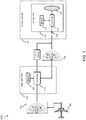
- a system for ground calibration of an aircraft weather radar (WxR) 100 may include an WxR alignment tool 102 configured to calibrate an calibrate an uncalibrated (UC) aircraft weather radar (WxR) 120 onboard an UC aircraft 150.
- WxR uncalibrated aircraft weather radar
- the UC WxR 120 may further comprise a new WxR in a new UC aircraft 150, a suspect WxR in a reference aircraft, a WxR on which a maintenance function has been performed, and an UC WxR in an UC aircraft 150 of a plurality of aircraft types.
- the UC WxR 120 may include a WxR controller 122 and a WxR memory 124.
- the WxR controller 122 may be operatively coupled to a communications port 126.
- the communications port may include an ethernet port or an additional type of wired port.
- the WxR alignment tool 102 may include an alignment tool controller 110 coupled with a tangible, non-transitory memory 106 configured to communicate with the alignment tool controller 110, the tangible, non-transitory memory 106 having instructions stored therein that, in response to execution by the alignment tool controller 110, cause the alignment tool controller 110 to carry out the function of the system for ground calibration of the WxR 100.
- the WxR alignment tool 102 may be incorporated within a portable WxR health monitor tool or an additional type of stand-alone portable device configured for communication with each of the calibrated WxR and the UC WxR 120, and supporting the alignment tool controller 110 processing and memory.
- FIG 2 SYSTEM FUNCTION
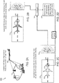
- the system function 200 of the system for ground calibration of the WxR 100 may include, represented within FIG. 2A , use of the reference aircraft 140 which has test flown and calibrated an onboard calibrated WxR.
- the system for ground calibration of the WxR 100 may then function to use the ground reference map 142 collected as the reference aircraft 140 is parked, FIG. 2B , in a specific ground position 212 and on a specific heading 214.
- the specific ground position 212 may include a position marked on a surface runway 210.
- the specific ground position 212 may include a plurality of positions desirable to a manufacturer or operator.
- a specific ground position 212 may include a latitude longitude or any coordinate system.
- one specific ground position 212 may include a latitude of N 47 30.0 and a longitude of W 122 13.0 on a specific heading 214 of 338.0 degrees magnetic.
- the reference aircraft 140 WxR may generate the reference ground map 142 by actively operating the calibrated WxR to illuminate surrounding terrain within a field of view (FOV) of the calibrated WxR.
- the calibrated WxR may receive radar returns from the FOV terrain (natural and man-made) and create an accurate picture of a WxR view of a local ground picture.
- the calibrated WxR may generate the reference ground map 142 over a minimum period in the specific ground position on the specific heading. For example, an exemplary seven to eight minute run time may be sufficient to generate the accurate ground reference map 142.
- a typical WxR FOV may include a plus or minus 60 degrees from the nose of the aircraft for a complete picture of 120 degrees. Additional FOV of WxR may fall directly within the scope of the inventive concepts herein.
- the alignment tool controller 110 may receive the reference ground map 142 which has been generated by the calibrated WxR onboard the reference aircraft 140 with the reference aircraft 140 parked in the specific ground position 212 and on the specific heading 214.
- the reception of the reference ground map may further include an output of the calibrated WxR ground reference map 142 via a health monitor port on the calibrated WxR.
- the alignment tool controller 110 may receive an UC ground map 152 produced by the UC WxR 120 via the communications port 126 during an active UC WxR 120 operation, FIG. 2C , with the UC aircraft 150 in the specific ground position 212 and on the specific heading 214.
- the alignment tool controller 110 may receive the UC ground map produced by the UC WxR 120 for a minimum period of the active UC WxR 120 operation in the specific ground position 212 on the specific heading 214. For example, a reception time of an exemplary seven to eight minutes may be sufficient for the alignment tool controller 110 to determine correct offset values.
- the alignment tool controller 110 may, FIG. 2D , compare 242 the UC ground map 152 to the reference ground map 142, determine 244 a delta between the UC ground map 152 and the reference ground map 142, and generate a pitch offset, a roll offset, and an elevation offset required reduce the delta to a desired operational value.
- the alignment tool controller 110 may determine what offsets are required in pitch roll and elevation to make the UC ground map 152 match the reference ground map 142.
- the desired operational value may fall within an exemplary approximately +/-0.25 deg of a calibrated value. In this manner, the system for ground calibration of the WxR 100 may align the UC WxR 120 to a standard operational tolerance for further operational use.
- the alignment tool controller 110 may calibrate the UC WxR 120 by applying the pitch offset, the roll offset and the elevation offset to the WxR memory 124 via the communications port 126.
- the WxR memory 124 may include a non-volatile memory (NVM) with a lockable portion capable of receiving and storing the offset values without corruption or loss.
- NVM non-volatile memory
- the alignment tool controller 110 may calibrate the UC WxR 120 by applying the pitch offset, the roll offset and the elevation offset to the WxR memory 124 via an initialization of a radar alignment servo within the UC WxR 120. In embodiments, the alignment tool controller 110 may log each of the offsets to a non-volatile portion of the memory 116 and load each of the offsets to the UC WxR upon a UC WxR power cycle.
- the WxR alignment tool 102 may function to compare an amplitude of the returns generated by the UC WxR 120 and determine the delta between those amplitudes generated by the UC WxR 120 to the amplitudes found in the reference ground map 142.
- the alignment tool 102 may be incorporated within a portable device capable of being carried from aircraft to aircraft and calibrate a plurality of UC WxR 120 on an associated plurality of UC aircraft 150 based on the comparison of each received UC ground map 152 with the ground reference map 142.
- FIG 3 SPECIFIC GROUND POSITION
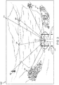
- the perspective view 300 may indicate a FOV of the UC WxR 120 as the UC WxR 120 is operated and the UC ground map is received by the alignment tool controller 110.
- the calibrated WxR and the UC WxR 120 may each illuminate a left sector tower 302, a group of left sector buildings 304, a center sector terrain 306, a right sector terrain 308, a right sector mountain 310, and a group of right sector buildings 312.
- the calibrated WxR may illuminate each of these features and collect the returns from each feature to accurately create the ground picture.
- the alignment tool controller 110 may determine the delta between the two pictures and apply correct offset values in pitch, roll, and elevation to calibrate the UC WxR 120.
- the specific ground position 212 combined with the specific heading 214 may offer the UC WxR 120 a FOV with a radar significant ground object within each of a left sector, a center sector, and a right sector of the UC WxR 120.
- the calibrated WxR may be unmodified while the alignment tool may perform the function of actively interrogating the calibrated WxR to retrieve the reference ground map 142 data from the calibrated WxR and storing the reference ground map 142 to the memory 106.
- the calibrated WxR may produce the ground reference map 142 and export the ground reference map 142 to the alignment tool controller 110 via a passive reception for storage within the memory 106.
- a test of the system for ground calibration of the WxR 100 may reveal an accurate determination of the offset values required to calibrate the UC WxR 120.
- Table 1 Pre-Set Elev. Offset (deg) Elev. Offset Correction (deg) -0.8 -0.76194 -0.4 -0.45579 +0.4 0.48919 +0.8 0.75949
- a calibrated offset may be compared with the computed offset values.
- a generally accepted tolerance may include a calculated combined offset from pitch and elevation may fall within an exemplary desired operational value of approximately +/-0.25 degrees of calibrated offset.
- Table 2 may indicate values generally acceptable within these tolerances. Table 2 Axis Calibrated Offset (deg) Computed Offset (deg) Pitch -0.516342 -0.47555 Roll 0.10906 0.079782 Elevation 0.28125 0.24043
- FIG 4 METHOD
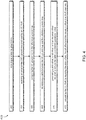
- a method 400 for ground calibration of an aircraft weather radar may include, at a step 402, receiving a reference ground map, the reference ground map 1) generated by a test flown reference aircraft weather radar (WxR) 2) onboard a reference aircraft 3) with the calibrated aircraft in a specific ground position, and 4) on a specific heading.
- WxR test flown reference aircraft weather radar
- a step 404 may include receiving an uncalibrated (UC) ground map produced by an UC WxR onboard an UC aircraft 1) during an active UC WxR operation, with the UC aircraft 2) in the specific ground position, and 3) on the specific heading.
- a step 406 may include comparing the UC ground map to the reference ground map and, at a step 408, determining a delta between the UC ground map and the reference ground map.
- the method may include, at a step 410, generating a pitch offset, a roll offset, and an elevation offset required reduce the delta to a desired operational value and, at a step 412, calibrating the UC WxR by applying the pitch offset, the roll offset and the elevation offset to a WxR memory.
- receiving the reference ground map 142 may further include a reception of the reference ground map 142 from a calibrated WxR and actively interrogating the calibrated WxR to determine the reference ground map.
- receiving the reference ground map 142 may further include a wired reception directly from the calibrated WxR, and a reception of the ground reference map from a source other than the calibrated WxR.
- the reference ground map may be stored on any storage device and loaded within a memory 106 of a plurality of alignment tools 102 to service a plurality of aircraft at the specific position 212.
- embodiments of the inventive concepts disclosed herein may provide a novel solution to initializing a newly installed weather radar system without requiring a test flight.
- embodiments of the methods according to the inventive concepts disclosed herein may include one or more of the steps described herein. Further, such steps may be carried out in any desired order and two or more of the steps may be carried out simultaneously with one another. Two or more of the steps disclosed herein may be combined in a single step, and in some embodiments, one or more of the steps may be carried out as two or more sub-steps. Further, other steps or sub-steps may be carried in addition to, or as substitutes to one or more of the steps disclosed herein.
Landscapes
- Engineering & Computer Science (AREA)
- Remote Sensing (AREA)
- Radar, Positioning & Navigation (AREA)
- Physics & Mathematics (AREA)
- Computer Networks & Wireless Communication (AREA)
- General Physics & Mathematics (AREA)
- Electromagnetism (AREA)
- Aviation & Aerospace Engineering (AREA)
- Radar Systems Or Details Thereof (AREA)
Abstract
Description
- An initialization of a weather radar system alignment servo for new aircraft may be a time-consuming and costly process requiring hours of flight test. Aircraft manufacturers may desire an easier and lower-cost approach to install and calibrate weather radar systems.
- After installation of a new or replacement weather radar (WxR) offset values in pitch, roll, and elevation may be set at zero. An operator must initialize or reinitialize the alignment servo offset values for accurate operational representation of weather within the field of view of the WxR antenna. Without a calibrated servo, the WxR may present an inaccurate picture of actual weather conditions and falsely display undesirable ground returns.
- Traditionally, a weather radar alignment servo initialization process may include a two to three-hour test flight with the aircraft in cruise flight, at least 17,000 ft above prevailing terrain in a field of view (FOV) of the weather radar. There must be terrain available in a left, a center, and a right display area of the weather radar flight deck display with no large bodies of water within the terrain area.
- The weather radar system must be operated in an auto tilt mode during a minimum of two minutes in unaccelerated level flight to start the alignment process. During the initialization, the servo monitors the ground terrain in the FOV and over time, the WxR is calibrated. There can be no significant weather, mountainous terrain or large variations in terrain between 80 and 140 NM or the two-minute requirement may be extended.
- Some calibration tools may be dependent on spatially placed external reflector devices or actual external transmitters to enable a calibration. However, often these reflector devices may be unavailable or poorly maintained.
- Therefore, a need remains for a system and related method which may overcome these limitations and provide a novel solution to initializing a newly installed weather radar system without requiring a test flight.
- In one aspect, embodiments of the inventive concepts disclosed herein are directed to a system for ground calibration of an aircraft weather radar. The system comprises an uncalibrated (UC) aircraft weather radar (WxR) onboard an UC aircraft, the UC WxR including a WxR controller and a WxR memory, the WxR controller operatively coupled to a communications port.
- The system also includes a WxR alignment tool including an alignment tool controller, the WxR alignment tool including a tangible, non-transitory memory configured to communicate with the alignment tool controller, the tangible, non-transitory memory having instructions stored therein that, in response to execution by the alignment tool controller, cause the alignment tool controller to carry out a plurality of functions in accordance with the system for ground calibration of an aircraft weather radar.
- The alignment tool controller receives a reference ground map, the reference ground map 1) generated by a test flown calibrated WxR 2) onboard a reference aircraft 3) with the reference aircraft in a specific ground position, and 4) on a specific heading and receive an UC ground map produced by the UC WxR via the communications port 1) during an active UC WxR operation, with the UC aircraft 2) in the specific ground position, and 3) on the specific heading.
- The alignment tool controller compares the UC ground map to the reference ground map and determine a delta between the UC ground map and the reference ground map. [0009] The alignment tool controller generates a pitch offset, a roll offset, and an elevation offset required to reduce the delta to a desired operational value and calibrate the UC WxR by applying the pitch offset, the roll offset and the elevation offset to the WxR memory via the communications port.
- A further embodiment of the inventive concepts disclosed herein may include a method for ground calibration of an aircraft weather radar. The method includes receiving a reference ground map, the reference ground map 1) generated by a reference aircraft weather radar (WxR) 2) onboard a reference aircraft 3) with the reference aircraft in a specific ground position, and 4) on a specific heading.
- The method includes receiving an uncalibrated (UC) ground map produced by an UC WxR onboard an UC aircraft 1) during an active UC WxR operation, with the UC aircraft 2) in the specific ground position, and 3) on the specific heading. The method may then include comparing the UC ground map to the reference ground map and determining a delta between the UC ground map and the reference ground map.
- To calibrate the UC WxR, the method includes generating a pitch offset, a roll offset, and an elevation offset required to reduce the delta to a desired operational value and calibrating the UC WxR by applying the pitch offset, the roll offset and the elevation offset to a WxR memory.
- It is to be understood that both the foregoing general description and the following detailed description are exemplary and explanatory only and are not necessarily restrictive of the inventive concepts as claimed. The accompanying drawings, which are incorporated in and constitute a part of the specification, illustrate embodiments of the inventive concepts and together with the general description, serve to explain the principles of the inventive concepts disclosed herein.
- Implementations of the inventive concepts disclosed herein may be better understood when consideration is given to the following detailed description thereof. Such description makes reference to the included drawings, which are not necessarily to scale, and in which some features may be exaggerated and some features may be omitted or may be represented schematically in the interest of clarity. Like reference numerals in the drawings may represent and refer to the same or similar element, feature, or function. In the drawings in which
-
FIG. 1 is a diagram of a system for ground calibration of an aircraft weather radar in accordance with an embodiment of the inventive concepts disclosed herein; -
FIGs. 2A-D are diagrams of a system function in accordance with an embodiment of the inventive concepts disclosed herein; -
FIG. 3 is a diagram of a perspective view of a ground calibration exemplary of an embodiment of the inventive concepts disclosed herein; and -
FIG. 4 is a diagram of a method flow exemplary of one embodiment of the inventive concepts disclosed herein. - Before explaining at least one embodiment of the inventive concepts disclosed herein in detail, it is to be understood that the inventive concepts are not limited in their application to the details of construction and the arrangement of the components or steps or methodologies set forth in the following description or illustrated in the drawings. In the following detailed description of embodiments of the instant inventive concepts, numerous specific details are set forth in order to provide a more thorough understanding of the inventive concepts. However, it will be apparent to one of ordinary skill in the art having the benefit of the instant disclosure that the inventive concepts disclosed herein may be practiced without these specific details. In other instances, well-known features may not be described in detail to avoid unnecessarily complicating the instant disclosure. The inventive concepts disclosed herein are capable of other embodiments or of being practiced or carried out in various ways. Also, it is to be understood that the phraseology and terminology employed herein is for the purpose of description and should not be regarded as limiting.
- As used herein a letter following a reference numeral is intended to reference an embodiment of the feature or element that may be similar, but not necessarily identical, to a previously described element or feature bearing the same reference numeral (e.g., 1, 1a, 1b). Such shorthand notations are used for purposes of convenience only, and should not be construed to limit the inventive concepts disclosed herein in any way unless expressly stated to the contrary.
- Further, unless expressly stated to the contrary, "or" refers to an inclusive or and not to an exclusive or. For example, a condition A or B is satisfied by anyone of the following: A is true (or present) and B is false (or not present), A is false (or not present) and B is true (or present), and both A and B are true (or present).
- In addition, use of the "a" or "an" are employed to describe elements and components of embodiments of the instant inventive concepts. This is done merely for convenience and to give a general sense of the inventive concepts, thus "a" and "an" are intended to include one or at least one and the singular also includes the plural unless it is obvious that it is meant otherwise.
- Finally, as used herein any reference to "one embodiment," or "some embodiments" means that a particular element, feature, structure, or characteristic described in connection with the embodiment is included in at least one embodiment of the inventive concepts disclosed herein. The appearances of the phrase "in some embodiments" in various places in the specification are not necessarily all referring to the same embodiment, and embodiments of the inventive concepts disclosed may include one or more of the features expressly described or inherently present herein, or any combination of sub-combination of two or more such features, along with any other features which may not necessarily be expressly described or inherently present in the instant disclosure.
- Broadly, embodiments of the inventive concepts disclosed herein are directed to a system and method for ground calibration of an aircraft weather radar (WxR) (100) employs a calibrated WxR already flight tested on a reference aircraft to generate a ground reference map from a specific ground position on a specific heading. A WxR alignment tool (102) receives the ground reference map and compares it to an uncalibrated ground map generated by an uncalibrated WxR in the same ground position and on the same heading. Once compared, the alignment tool determines a delta between the ground reference map and the uncalibrated ground map and determines offset values in pitch, roll, and elevation to reduce the delta to a desired operational value and make the maps nearly identical. The alignment tool then applies to offset values to the uncalibrated WxR to calibrate the WxR for operational use.
REFERENCE CHART System for Ground Calibration of an Aircraft 100 Weather Radar (WxR) 102 WxR Alignment Tool 106 Memory 110 Alignment Tool Controller 120 Uncalibrated WxR 122 WxR Controller 124 WxR Memory 126 Communications Port 128 WxR Antenna 140 Reference Aircraft 142 Reference Ground Map 150 Uncalibrated Aircraft 152 UC Ground Map 200 System Function 210 Surface Runway 212 Specific Ground Position 214 Specific Heading 242 Compare 244 Determine Offset Values 300 Perspective View 302 Left Sector Tower 304 Left Sector Buildings 306 Center Sector Terrain 308 Right Sector Terrain 310 Right Sector Mountain 312 Right Sector Buildings 400 Method Flow - Referring now to
FIG. 1 , a diagram of a system for ground calibration of an aircraft weather radar in accordance with an embodiment of the inventive concepts disclosed herein is shown. Generally, a system for ground calibration of an aircraft weather radar (WxR) 100 may include anWxR alignment tool 102 configured to calibrate an calibrate an uncalibrated (UC) aircraft weather radar (WxR) 120 onboard an UCaircraft 150. - In embodiments, the the UC WxR 120 may further comprise a new WxR in a new UC
aircraft 150, a suspect WxR in a reference aircraft, a WxR on which a maintenance function has been performed, and an UC WxR in an UCaircraft 150 of a plurality of aircraft types. - In one embodiment of the inventive concepts disclosed herein, the UC
WxR 120 may include aWxR controller 122 and aWxR memory 124. Here, theWxR controller 122 may be operatively coupled to acommunications port 126. In embodiments, the communications port may include an ethernet port or an additional type of wired port. - In one embodiment of the inventive concepts disclosed herein, the
WxR alignment tool 102 may include analignment tool controller 110 coupled with a tangible,non-transitory memory 106 configured to communicate with thealignment tool controller 110, the tangible,non-transitory memory 106 having instructions stored therein that, in response to execution by thealignment tool controller 110, cause thealignment tool controller 110 to carry out the function of the system for ground calibration of theWxR 100. - In embodiments, the
WxR alignment tool 102 may be incorporated within a portable WxR health monitor tool or an additional type of stand-alone portable device configured for communication with each of the calibrated WxR and theUC WxR 120, and supporting thealignment tool controller 110 processing and memory. - Referring now to
FIGs. 2A-D , diagrams of a system function in accordance with an embodiment of the inventive concepts disclosed herein are shown. Thesystem function 200 of the system for ground calibration of theWxR 100 may include, represented withinFIG. 2A , use of thereference aircraft 140 which has test flown and calibrated an onboard calibrated WxR. The system for ground calibration of theWxR 100 may then function to use theground reference map 142 collected as thereference aircraft 140 is parked,FIG. 2B , in aspecific ground position 212 and on aspecific heading 214. In one embodiment of the inventive concepts disclosed herein, thespecific ground position 212 may include a position marked on asurface runway 210. Thespecific ground position 212 may include a plurality of positions desirable to a manufacturer or operator. - On one exemplary embodiment, a
specific ground position 212 may include a latitude longitude or any coordinate system. For example, onespecific ground position 212 may include a latitude of N 47 30.0 and a longitude ofW 122 13.0 on a specific heading 214 of 338.0 degrees magnetic. - While parked on
specific position 212 and heading 214, thereference aircraft 140 WxR may generate thereference ground map 142 by actively operating the calibrated WxR to illuminate surrounding terrain within a field of view (FOV) of the calibrated WxR. The calibrated WxR may receive radar returns from the FOV terrain (natural and man-made) and create an accurate picture of a WxR view of a local ground picture. - In embodiments, the calibrated WxR may generate the
reference ground map 142 over a minimum period in the specific ground position on the specific heading. For example, an exemplary seven to eight minute run time may be sufficient to generate the accurateground reference map 142. - A typical WxR FOV may include a plus or minus 60 degrees from the nose of the aircraft for a complete picture of 120 degrees. Additional FOV of WxR may fall directly within the scope of the inventive concepts herein.
- In one embodiment of the inventive concepts disclosed herein, the
alignment tool controller 110 may receive thereference ground map 142 which has been generated by the calibrated WxR onboard thereference aircraft 140 with thereference aircraft 140 parked in thespecific ground position 212 and on thespecific heading 214. - In one embodiment of the inventive concepts disclosed herein, the reception of the reference ground map may further include an output of the calibrated WxR
ground reference map 142 via a health monitor port on the calibrated WxR. - The
alignment tool controller 110 may receive anUC ground map 152 produced by theUC WxR 120 via thecommunications port 126 during anactive UC WxR 120 operation,FIG. 2C , with theUC aircraft 150 in thespecific ground position 212 and on thespecific heading 214. - In embodiments, the
alignment tool controller 110 may receive the UC ground map produced by theUC WxR 120 for a minimum period of theactive UC WxR 120 operation in thespecific ground position 212 on thespecific heading 214. For example, a reception time of an exemplary seven to eight minutes may be sufficient for thealignment tool controller 110 to determine correct offset values. - Here, if the
UC WxR 120 were calibrated, the local ground picture produced by theUC WxR 120 and theground reference map 142 may be the same. Thealignment tool controller 110 may,FIG. 2D , compare 242 theUC ground map 152 to thereference ground map 142, determine 244 a delta between theUC ground map 152 and thereference ground map 142, and generate a pitch offset, a roll offset, and an elevation offset required reduce the delta to a desired operational value. - In reduce the delta to a desired operational value, the
alignment tool controller 110 may determine what offsets are required in pitch roll and elevation to make theUC ground map 152 match thereference ground map 142. In one example, the desired operational value may fall within an exemplary approximately +/-0.25 deg of a calibrated value. In this manner, the system for ground calibration of theWxR 100 may align theUC WxR 120 to a standard operational tolerance for further operational use. - Once determined, the
alignment tool controller 110 may calibrate theUC WxR 120 by applying the pitch offset, the roll offset and the elevation offset to theWxR memory 124 via thecommunications port 126. In one embodiment of the inventive concepts disclosed herein, theWxR memory 124 may include a non-volatile memory (NVM) with a lockable portion capable of receiving and storing the offset values without corruption or loss. - In embodiments, the
alignment tool controller 110 may calibrate theUC WxR 120 by applying the pitch offset, the roll offset and the elevation offset to theWxR memory 124 via an initialization of a radar alignment servo within theUC WxR 120. In embodiments, thealignment tool controller 110 may log each of the offsets to a non-volatile portion of the memory 116 and load each of the offsets to the UC WxR upon a UC WxR power cycle. - In one embodiment of the inventive concepts disclosed herein, the
WxR alignment tool 102 may function to compare an amplitude of the returns generated by theUC WxR 120 and determine the delta between those amplitudes generated by theUC WxR 120 to the amplitudes found in thereference ground map 142. - In one embodiment of the inventive concepts disclosed herein, the
alignment tool 102 may be incorporated within a portable device capable of being carried from aircraft to aircraft and calibrate a plurality ofUC WxR 120 on an associated plurality ofUC aircraft 150 based on the comparison of each receivedUC ground map 152 with theground reference map 142. - Referring now to
FIG. 3 , a diagram of a perspective view of a ground calibration exemplary of an embodiment of the inventive concepts disclosed herein is shown. Theperspective view 300 may indicate a FOV of theUC WxR 120 as theUC WxR 120 is operated and the UC ground map is received by thealignment tool controller 110. The calibrated WxR and theUC WxR 120 may each illuminate aleft sector tower 302, a group ofleft sector buildings 304, acenter sector terrain 306, aright sector terrain 308, aright sector mountain 310, and a group ofright sector buildings 312. In producing theground reference map 142, the calibrated WxR may illuminate each of these features and collect the returns from each feature to accurately create the ground picture. - Then, as the
alignment tool controller 110 monitors theUC WxR 120 while it is illuminating the same features 302 - 312 from the samespecific position 212 and heading 214, thealignment tool controller 110 may determine the delta between the two pictures and apply correct offset values in pitch, roll, and elevation to calibrate theUC WxR 120. - In embodiments, the
specific ground position 212 combined with the specific heading 214 may offer the UC WxR 120 a FOV with a radar significant ground object within each of a left sector, a center sector, and a right sector of theUC WxR 120. - In one embodiment of the inventive concepts disclosed herein, the calibrated WxR may be unmodified while the alignment tool may perform the function of actively interrogating the calibrated WxR to retrieve the
reference ground map 142 data from the calibrated WxR and storing thereference ground map 142 to thememory 106. In additional embodiments, the calibrated WxR may produce theground reference map 142 and export theground reference map 142 to thealignment tool controller 110 via a passive reception for storage within thememory 106. - In one embodiment of the inventive concepts disclosed herein, a test of the system for ground calibration of the
WxR 100 may reveal an accurate determination of the offset values required to calibrate theUC WxR 120. Indicated in Table 1, a preset offset error in elevation was entered and thealignment tool controller 110 was allowed to determine offset correction values to correct the error.Table 1 Pre-Set Elev. Offset (deg) Elev. Offset Correction (deg) -0.8 -0.76194 -0.4 -0.45579 +0.4 0.48919 +0.8 0.75949 - To verify the
alignment tool controller 110 may compute a correct offset value within tolerance foraccurate UC WxR 120 operation, a calibrated offset may be compared with the computed offset values. For accurate WxR alignment and future WxR flight operation without an undesirable clutter leakage, a generally accepted tolerance may include a calculated combined offset from pitch and elevation may fall within an exemplary desired operational value of approximately +/-0.25 degrees of calibrated offset. Table 2 may indicate values generally acceptable within these tolerances.Table 2 Axis Calibrated Offset (deg) Computed Offset (deg) Pitch -0.516342 -0.47555 Roll 0.10906 0.079782 Elevation 0.28125 0.24043 - Referring now to
FIG. 4 , a diagram of a method flow exemplary of one embodiment of the inventive concepts disclosed herein is shown. Amethod 400 for ground calibration of an aircraft weather radar may include, at astep 402, receiving a reference ground map, the reference ground map 1) generated by a test flown reference aircraft weather radar (WxR) 2) onboard a reference aircraft 3) with the calibrated aircraft in a specific ground position, and 4) on a specific heading. - A
step 404 may include receiving an uncalibrated (UC) ground map produced by an UC WxR onboard an UC aircraft 1) during an active UC WxR operation, with the UC aircraft 2) in the specific ground position, and 3) on the specific heading. Astep 406 may include comparing the UC ground map to the reference ground map and, at astep 408, determining a delta between the UC ground map and the reference ground map. - The method may include, at a
step 410, generating a pitch offset, a roll offset, and an elevation offset required reduce the delta to a desired operational value and, at astep 412, calibrating the UC WxR by applying the pitch offset, the roll offset and the elevation offset to a WxR memory. - In one embodiment of the inventive concepts disclosed herein, receiving the
reference ground map 142 may further include a reception of thereference ground map 142 from a calibrated WxR and actively interrogating the calibrated WxR to determine the reference ground map. - Also, receiving the
reference ground map 142 may further include a wired reception directly from the calibrated WxR, and a reception of the ground reference map from a source other than the calibrated WxR. For example, the reference ground map may be stored on any storage device and loaded within amemory 106 of a plurality ofalignment tools 102 to service a plurality of aircraft at thespecific position 212. - As will be appreciated from the above description, embodiments of the inventive concepts disclosed herein may provide a novel solution to initializing a newly installed weather radar system without requiring a test flight.
- It is to be understood that embodiments of the methods according to the inventive concepts disclosed herein may include one or more of the steps described herein. Further, such steps may be carried out in any desired order and two or more of the steps may be carried out simultaneously with one another. Two or more of the steps disclosed herein may be combined in a single step, and in some embodiments, one or more of the steps may be carried out as two or more sub-steps. Further, other steps or sub-steps may be carried in addition to, or as substitutes to one or more of the steps disclosed herein.
- From the above description, it is clear that the inventive concepts disclosed herein are well adapted to carry out the objects and to attain the advantages mentioned herein as well as those inherent in the inventive concepts disclosed herein. While presently preferred embodiments of the inventive concepts disclosed herein have been described for purposes of this disclosure, it will be understood that numerous changes may be made which will readily suggest themselves to those skilled in the art and which are within the scope of the invention as defined by the claims.
Claims (15)
- A system for ground calibration of an aircraft weather radar, comprising:an uncalibrated, UC, aircraft weather radar, WxR, (100) onboard an UC aircraft (150);the UC WxR including a WxR controller (122) and a WxR memory (124);the WxR controller operatively coupled to a communications port (126);a WxR alignment tool (102) including an alignment tool controller (110);the WxR alignment tool including a tangible, non-transitory memory (106) configured to communicate with the alignment tool controller, the tangible, non-transitory memory having instructions stored therein that, in response to execution by the alignment tool controller, cause the alignment tool controller to:receive a reference ground map, the reference ground map 1) generated by a test flown calibrated WxR 2) onboard a reference aircraft 3) with the reference aircraft in a specific ground position, and 4) on a specific heading;receive an UC ground map produced by the UC WxR via the communications port 1) during an active UC WxR operation, with the UC aircraft 2) in the specific ground position, and 3) on the specific heading;compare the UC ground map to the reference ground map;determine a delta between the UC ground map and the reference ground map;generate a pitch offset, a roll offset, and an elevation offset required to reduce the delta to a desired operational value; andcalibrate the UC WxR by applying the pitch offset, the roll offset and the elevation offset to the WxR memory via the communications port.
- The system for ground calibration of an aircraft weather radar of claim 1, wherein the UC WxR further comprises a new WxR in a new UC aircraft, a suspect WxR in a reference aircraft, a WxR on which a maintenance function has been performed, and the UC WxR in an UC aircraft of a plurality of aircraft types.
- The system for ground calibration of an aircraft weather radar of claim 1 or 2, wherein calibrating the UC WxR further comprises logging each of the offsets to a non-volatile portion of the memory and loading each of the offsets to the UC WxR upon a UC WxR power cycle.
- The system for ground calibration of an aircraft weather radar of any preceding claim, wherein the WxR alignment tool (102) is further incorporated within one of: a portable WxR health monitor tool and a stand-alone portable device configured for communicating with each of the calibrated WxR and the UC WxR, and supporting the alignment tool controller processing and memory.
- The system for ground calibration of an aircraft weather radar of any preceding claim, wherein the specific ground position combined with the specific heading offers the UC WxR a field of view with a radar significant ground object within a plus or minus 60 degrees of the specific heading.
- The system for ground calibration of an aircraft weather radar of any preceding claim, wherein receiving the reference ground map further comprises an output of the calibrated WxR ground reference map via a health monitor port.
- The system for ground calibration of an aircraft weather radar of any preceding claim, wherein the reference ground map is generated by the calibrated WxR over a minimum period in the specific ground position on the specific heading.
- The system for ground calibration of an aircraft weather radar of any preceding claim, wherein receiving the UC ground map produced by the UC WxR further comprises a minimum period of the active UC WxR operation in the specific ground position on the specific heading.
- The system for ground calibration of an aircraft weather radar of any preceding claim, wherein the communications port further comprises one of: an ethernet port, or an additional wired port.
- The system for ground calibration of an aircraft weather radar of any preceding claim, wherein calibrating the UC WxR by applying the pitch offset, the roll offset and the elevation offset to the WxR memory further comprises an initialization of a radar alignment servo within the UC WxR.
- A method for ground calibration of an aircraft weather radar, comprising:receiving a reference ground map, the reference ground map 1) generated by a test flown reference aircraft weather radar, WxR, 2), onboard a reference aircraft 3) with the reference aircraft in a specific ground position, and 4) on a specific heading;receiving an uncalibrated, UC, ground map produced by an UC WxR onboard an UC aircraft 1) during an active UC WxR operation, with the UC aircraft 2) in the specific ground position, and 3) on the specific heading;comparing the UC ground map to the reference ground map;determining a delta between the UC ground map and the reference ground map;generating a pitch offset, a roll offset, and an elevation offset required to reduce the delta to a desired value; andcalibrating the UC WxR by applying the pitch offset, the roll offset and the elevation offset to a WxR memory.
- The method for ground calibration of an aircraft weather radar of claim 11, wherein receiving the reference ground map further comprises one of a passive reception of the reference ground map from a calibrated WxR and actively interrogating the calibrated WxR to determine the reference ground map.
- The method for ground calibration of an aircraft weather radar of claim 11 or 12, wherein receiving the reference ground map further comprises a wired reception directly from the calibrated WxR, and a reception of the ground reference map from a source other than the calibrated WxR.
- The method for ground calibration of an aircraft weather radar of claim 11, 12 or 13, wherein comparing the ground map produced by the active UC WxR operation to the reference ground map further comprises comparing an amplitude of at least one return received during the receiving the UC ground map to at least one amplitude of the reference ground map.
- The method for ground calibration of an aircraft weather radar of any of claims 11 to 14, wherein receiving the UC ground map produced by the UC WxR further comprises a minimum period of the active UC WxR operation in the specific ground position on the specific heading.
Applications Claiming Priority (1)
| Application Number | Priority Date | Filing Date | Title |
|---|---|---|---|
| US16/743,994 US11294050B2 (en) | 2020-01-15 | 2020-01-15 | Automatic ground initialization of radar alignment servo |
Publications (2)
| Publication Number | Publication Date |
|---|---|
| EP3851877A1 true EP3851877A1 (en) | 2021-07-21 |
| EP3851877B1 EP3851877B1 (en) | 2023-08-09 |
Family
ID=74186535
Family Applications (1)
| Application Number | Title | Priority Date | Filing Date |
|---|---|---|---|
| EP21151909.5A Active EP3851877B1 (en) | 2020-01-15 | 2021-01-15 | Automatic ground initialization of radar alignment servo |
Country Status (2)
| Country | Link |
|---|---|
| US (1) | US11294050B2 (en) |
| EP (1) | EP3851877B1 (en) |
Families Citing this family (1)
| Publication number | Priority date | Publication date | Assignee | Title |
|---|---|---|---|---|
| US20250208257A1 (en) * | 2023-12-21 | 2025-06-26 | Honeywell International Inc. | Detecting hardware failure in a radar system based on comparing actual and expected radar data |
Citations (4)
| Publication number | Priority date | Publication date | Assignee | Title |
|---|---|---|---|---|
| US4283725A (en) * | 1979-10-09 | 1981-08-11 | Chisholm John P | In-flight aircraft weather radar calibration |
| WO1994029742A1 (en) * | 1993-06-11 | 1994-12-22 | Republic Electronics Co. | Windshear radar test systems and methods |
| EP2246933A1 (en) * | 2009-04-27 | 2010-11-03 | Honeywell International Inc. | Self-stabilizing antenna base |
| WO2016025683A1 (en) * | 2014-08-15 | 2016-02-18 | Robert Bosch Gmbh | Automotive radar alignment |
Family Cites Families (11)
| Publication number | Priority date | Publication date | Assignee | Title |
|---|---|---|---|---|
| US5467092A (en) | 1994-05-31 | 1995-11-14 | Alliedsignal Inc. | Radar system including stabilization calibration arrangement |
| US6008754A (en) | 1996-08-15 | 1999-12-28 | Alliedsignal Inc. | On-ground radio altimeter calibration system |
| US7138940B2 (en) | 2004-07-22 | 2006-11-21 | Honeywell International Inc. | Method and systems for automatic zero calibration of radar altimeters |
| US7183969B2 (en) | 2004-12-22 | 2007-02-27 | Raytheon Company | System and technique for calibrating radar arrays |
| US7522096B2 (en) | 2007-04-09 | 2009-04-21 | Honeywell International Inc | Method for phase calibrating antennas in a radar system |
| FR2978249B1 (en) | 2011-07-22 | 2013-07-26 | Thales Sa | CALIBRATION AND TEST DEVICE FOR AN ACTIVE ANTENNA, IN PARTICULAR AN ADVANCED ANTENNA FOR AN AIRBORNE RADAR |
| US9903719B2 (en) * | 2013-09-03 | 2018-02-27 | Litel Instruments | System and method for advanced navigation |
| US10002469B2 (en) * | 2016-09-09 | 2018-06-19 | The University Of Hong Kong | Inclinometer methods and systems for generating and calibrating an in-vehicle inclination angle |
| EP3502740B1 (en) | 2017-12-21 | 2020-10-28 | Veoneer Sweden AB | Radar calibration in a near-static environment |
| US10997737B2 (en) * | 2019-05-02 | 2021-05-04 | GM Global Technology Operations LLC | Method and system for aligning image data from a vehicle camera |
| US12117569B2 (en) * | 2019-10-15 | 2024-10-15 | Cepton Technologies, Inc. | Dynamic calibration of lidar sensors |
-
2020
- 2020-01-15 US US16/743,994 patent/US11294050B2/en active Active
-
2021
- 2021-01-15 EP EP21151909.5A patent/EP3851877B1/en active Active
Patent Citations (4)
| Publication number | Priority date | Publication date | Assignee | Title |
|---|---|---|---|---|
| US4283725A (en) * | 1979-10-09 | 1981-08-11 | Chisholm John P | In-flight aircraft weather radar calibration |
| WO1994029742A1 (en) * | 1993-06-11 | 1994-12-22 | Republic Electronics Co. | Windshear radar test systems and methods |
| EP2246933A1 (en) * | 2009-04-27 | 2010-11-03 | Honeywell International Inc. | Self-stabilizing antenna base |
| WO2016025683A1 (en) * | 2014-08-15 | 2016-02-18 | Robert Bosch Gmbh | Automotive radar alignment |
Also Published As
| Publication number | Publication date |
|---|---|
| EP3851877B1 (en) | 2023-08-09 |
| US11294050B2 (en) | 2022-04-05 |
| US20210215823A1 (en) | 2021-07-15 |
Similar Documents
| Publication | Publication Date | Title |
|---|---|---|
| US7667645B2 (en) | GPS gyro calibration | |
| KR102813410B1 (en) | Method and system for calibrating a radar rotary antenna system | |
| CN106291488B (en) | A kind of Radar Calibration error calibration method | |
| US7561098B2 (en) | System and method for estimating airborne radar antenna pointing errors | |
| US20030016172A1 (en) | Satellite-tracking antenna controlling apparatus | |
| US20210231773A1 (en) | Method and apparatus for detecting radar wave offset | |
| US6646598B1 (en) | Antenna boresighting method | |
| US20180038963A1 (en) | Position and azimuth measurement device and surveying device | |
| CN116126034B (en) | Photoelectric calibration method for shipborne measurement and control antenna | |
| EP3851877B1 (en) | Automatic ground initialization of radar alignment servo | |
| US8077080B2 (en) | Calibration to improve weather radar positioning determination | |
| JP2000213934A (en) | Inclination sensor and its precision adjusting method | |
| Schwerdt et al. | TerraSAR-X calibration results | |
| CN113804219A (en) | Method and equipment for calibrating angle error coefficient of parabolic antenna based on astrometry | |
| CN109387816B (en) | System and method for calibrating a transmitting unit and watercraft | |
| GB2573090A (en) | Calibration of object position-measuring apparatus | |
| EP2669701A1 (en) | Calibration to improve weather radar positioning determination | |
| CN114167369A (en) | Height measurement precision improving technology based on antenna array surface calibration | |
| de Dios Yáñez-Ávila et al. | Adaptive solar tracking system for pyrheliometers | |
| CN113847933B (en) | Astronomical navigation system shafting parameter calibration method | |
| CN112697170A (en) | Method for calibrating more than two inclination angle sensors on carrier | |
| CN110686565A (en) | Zero position and true north calibration device and calibration method for vehicle-mounted 30 mm artillery system | |
| CN117213524A (en) | Azimuth calibration method and calibration system of cradle head equipment | |
| CN111458685B (en) | Remote monitoring system, monitoring method and integrated controller | |
| CN119716926B (en) | A method and system for correcting tracking deviations of low-Earth orbit satellite signals |
Legal Events
| Date | Code | Title | Description |
|---|---|---|---|
| PUAI | Public reference made under article 153(3) epc to a published international application that has entered the european phase |
Free format text: ORIGINAL CODE: 0009012 |
|
| STAA | Information on the status of an ep patent application or granted ep patent |
Free format text: STATUS: THE APPLICATION HAS BEEN PUBLISHED |
|
| AK | Designated contracting states |
Kind code of ref document: A1 Designated state(s): AL AT BE BG CH CY CZ DE DK EE ES FI FR GB GR HR HU IE IS IT LI LT LU LV MC MK MT NL NO PL PT RO RS SE SI SK SM TR |
|
| STAA | Information on the status of an ep patent application or granted ep patent |
Free format text: STATUS: REQUEST FOR EXAMINATION WAS MADE |
|
| 17P | Request for examination filed |
Effective date: 20220121 |
|
| RBV | Designated contracting states (corrected) |
Designated state(s): AL AT BE BG CH CY CZ DE DK EE ES FI FR GB GR HR HU IE IS IT LI LT LU LV MC MK MT NL NO PL PT RO RS SE SI SK SM TR |
|
| GRAP | Despatch of communication of intention to grant a patent |
Free format text: ORIGINAL CODE: EPIDOSNIGR1 |
|
| RIC1 | Information provided on ipc code assigned before grant |
Ipc: G01S 7/40 20060101ALI20230209BHEP Ipc: G01S 13/95 20060101AFI20230209BHEP |
|
| STAA | Information on the status of an ep patent application or granted ep patent |
Free format text: STATUS: GRANT OF PATENT IS INTENDED |
|
| INTG | Intention to grant announced |
Effective date: 20230316 |
|
| GRAS | Grant fee paid |
Free format text: ORIGINAL CODE: EPIDOSNIGR3 |
|
| GRAA | (expected) grant |
Free format text: ORIGINAL CODE: 0009210 |
|
| STAA | Information on the status of an ep patent application or granted ep patent |
Free format text: STATUS: THE PATENT HAS BEEN GRANTED |
|
| AK | Designated contracting states |
Kind code of ref document: B1 Designated state(s): AL AT BE BG CH CY CZ DE DK EE ES FI FR GB GR HR HU IE IS IT LI LT LU LV MC MK MT NL NO PL PT RO RS SE SI SK SM TR |
|
| REG | Reference to a national code |
Ref country code: GB Ref legal event code: FG4D |
|
| REG | Reference to a national code |
Ref country code: CH Ref legal event code: EP |
|
| REG | Reference to a national code |
Ref country code: DE Ref legal event code: R096 Ref document number: 602021004035 Country of ref document: DE |
|
| REG | Reference to a national code |
Ref country code: IE Ref legal event code: FG4D |
|
| REG | Reference to a national code |
Ref country code: LT Ref legal event code: MG9D |
|
| REG | Reference to a national code |
Ref country code: NL Ref legal event code: MP Effective date: 20230809 |
|
| REG | Reference to a national code |
Ref country code: AT Ref legal event code: MK05 Ref document number: 1598157 Country of ref document: AT Kind code of ref document: T Effective date: 20230809 |
|
| PG25 | Lapsed in a contracting state [announced via postgrant information from national office to epo] |
Ref country code: GR Free format text: LAPSE BECAUSE OF FAILURE TO SUBMIT A TRANSLATION OF THE DESCRIPTION OR TO PAY THE FEE WITHIN THE PRESCRIBED TIME-LIMIT Effective date: 20231110 |
|
| PG25 | Lapsed in a contracting state [announced via postgrant information from national office to epo] |
Ref country code: IS Free format text: LAPSE BECAUSE OF FAILURE TO SUBMIT A TRANSLATION OF THE DESCRIPTION OR TO PAY THE FEE WITHIN THE PRESCRIBED TIME-LIMIT Effective date: 20231209 |
|
| PG25 | Lapsed in a contracting state [announced via postgrant information from national office to epo] |
Ref country code: SE Free format text: LAPSE BECAUSE OF FAILURE TO SUBMIT A TRANSLATION OF THE DESCRIPTION OR TO PAY THE FEE WITHIN THE PRESCRIBED TIME-LIMIT Effective date: 20230809 Ref country code: RS Free format text: LAPSE BECAUSE OF FAILURE TO SUBMIT A TRANSLATION OF THE DESCRIPTION OR TO PAY THE FEE WITHIN THE PRESCRIBED TIME-LIMIT Effective date: 20230809 Ref country code: PT Free format text: LAPSE BECAUSE OF FAILURE TO SUBMIT A TRANSLATION OF THE DESCRIPTION OR TO PAY THE FEE WITHIN THE PRESCRIBED TIME-LIMIT Effective date: 20231211 Ref country code: NO Free format text: LAPSE BECAUSE OF FAILURE TO SUBMIT A TRANSLATION OF THE DESCRIPTION OR TO PAY THE FEE WITHIN THE PRESCRIBED TIME-LIMIT Effective date: 20231109 Ref country code: NL Free format text: LAPSE BECAUSE OF FAILURE TO SUBMIT A TRANSLATION OF THE DESCRIPTION OR TO PAY THE FEE WITHIN THE PRESCRIBED TIME-LIMIT Effective date: 20230809 Ref country code: LV Free format text: LAPSE BECAUSE OF FAILURE TO SUBMIT A TRANSLATION OF THE DESCRIPTION OR TO PAY THE FEE WITHIN THE PRESCRIBED TIME-LIMIT Effective date: 20230809 Ref country code: LT Free format text: LAPSE BECAUSE OF FAILURE TO SUBMIT A TRANSLATION OF THE DESCRIPTION OR TO PAY THE FEE WITHIN THE PRESCRIBED TIME-LIMIT Effective date: 20230809 Ref country code: IS Free format text: LAPSE BECAUSE OF FAILURE TO SUBMIT A TRANSLATION OF THE DESCRIPTION OR TO PAY THE FEE WITHIN THE PRESCRIBED TIME-LIMIT Effective date: 20231209 Ref country code: HR Free format text: LAPSE BECAUSE OF FAILURE TO SUBMIT A TRANSLATION OF THE DESCRIPTION OR TO PAY THE FEE WITHIN THE PRESCRIBED TIME-LIMIT Effective date: 20230809 Ref country code: GR Free format text: LAPSE BECAUSE OF FAILURE TO SUBMIT A TRANSLATION OF THE DESCRIPTION OR TO PAY THE FEE WITHIN THE PRESCRIBED TIME-LIMIT Effective date: 20231110 Ref country code: FI Free format text: LAPSE BECAUSE OF FAILURE TO SUBMIT A TRANSLATION OF THE DESCRIPTION OR TO PAY THE FEE WITHIN THE PRESCRIBED TIME-LIMIT Effective date: 20230809 Ref country code: AT Free format text: LAPSE BECAUSE OF FAILURE TO SUBMIT A TRANSLATION OF THE DESCRIPTION OR TO PAY THE FEE WITHIN THE PRESCRIBED TIME-LIMIT Effective date: 20230809 |
|
| PG25 | Lapsed in a contracting state [announced via postgrant information from national office to epo] |
Ref country code: PL Free format text: LAPSE BECAUSE OF FAILURE TO SUBMIT A TRANSLATION OF THE DESCRIPTION OR TO PAY THE FEE WITHIN THE PRESCRIBED TIME-LIMIT Effective date: 20230809 |
|
| PG25 | Lapsed in a contracting state [announced via postgrant information from national office to epo] |
Ref country code: ES Free format text: LAPSE BECAUSE OF FAILURE TO SUBMIT A TRANSLATION OF THE DESCRIPTION OR TO PAY THE FEE WITHIN THE PRESCRIBED TIME-LIMIT Effective date: 20230809 |
|
| PG25 | Lapsed in a contracting state [announced via postgrant information from national office to epo] |
Ref country code: SM Free format text: LAPSE BECAUSE OF FAILURE TO SUBMIT A TRANSLATION OF THE DESCRIPTION OR TO PAY THE FEE WITHIN THE PRESCRIBED TIME-LIMIT Effective date: 20230809 Ref country code: RO Free format text: LAPSE BECAUSE OF FAILURE TO SUBMIT A TRANSLATION OF THE DESCRIPTION OR TO PAY THE FEE WITHIN THE PRESCRIBED TIME-LIMIT Effective date: 20230809 Ref country code: ES Free format text: LAPSE BECAUSE OF FAILURE TO SUBMIT A TRANSLATION OF THE DESCRIPTION OR TO PAY THE FEE WITHIN THE PRESCRIBED TIME-LIMIT Effective date: 20230809 Ref country code: EE Free format text: LAPSE BECAUSE OF FAILURE TO SUBMIT A TRANSLATION OF THE DESCRIPTION OR TO PAY THE FEE WITHIN THE PRESCRIBED TIME-LIMIT Effective date: 20230809 Ref country code: DK Free format text: LAPSE BECAUSE OF FAILURE TO SUBMIT A TRANSLATION OF THE DESCRIPTION OR TO PAY THE FEE WITHIN THE PRESCRIBED TIME-LIMIT Effective date: 20230809 Ref country code: CZ Free format text: LAPSE BECAUSE OF FAILURE TO SUBMIT A TRANSLATION OF THE DESCRIPTION OR TO PAY THE FEE WITHIN THE PRESCRIBED TIME-LIMIT Effective date: 20230809 Ref country code: SK Free format text: LAPSE BECAUSE OF FAILURE TO SUBMIT A TRANSLATION OF THE DESCRIPTION OR TO PAY THE FEE WITHIN THE PRESCRIBED TIME-LIMIT Effective date: 20230809 |
|
| REG | Reference to a national code |
Ref country code: DE Ref legal event code: R097 Ref document number: 602021004035 Country of ref document: DE |
|
| PG25 | Lapsed in a contracting state [announced via postgrant information from national office to epo] |
Ref country code: IT Free format text: LAPSE BECAUSE OF FAILURE TO SUBMIT A TRANSLATION OF THE DESCRIPTION OR TO PAY THE FEE WITHIN THE PRESCRIBED TIME-LIMIT Effective date: 20230809 |
|
| PLBE | No opposition filed within time limit |
Free format text: ORIGINAL CODE: 0009261 |
|
| STAA | Information on the status of an ep patent application or granted ep patent |
Free format text: STATUS: NO OPPOSITION FILED WITHIN TIME LIMIT |
|
| 26N | No opposition filed |
Effective date: 20240513 |
|
| PG25 | Lapsed in a contracting state [announced via postgrant information from national office to epo] |
Ref country code: SI Free format text: LAPSE BECAUSE OF FAILURE TO SUBMIT A TRANSLATION OF THE DESCRIPTION OR TO PAY THE FEE WITHIN THE PRESCRIBED TIME-LIMIT Effective date: 20230809 |
|
| PG25 | Lapsed in a contracting state [announced via postgrant information from national office to epo] |
Ref country code: MC Free format text: LAPSE BECAUSE OF FAILURE TO SUBMIT A TRANSLATION OF THE DESCRIPTION OR TO PAY THE FEE WITHIN THE PRESCRIBED TIME-LIMIT Effective date: 20230809 |
|
| PG25 | Lapsed in a contracting state [announced via postgrant information from national office to epo] |
Ref country code: MC Free format text: LAPSE BECAUSE OF FAILURE TO SUBMIT A TRANSLATION OF THE DESCRIPTION OR TO PAY THE FEE WITHIN THE PRESCRIBED TIME-LIMIT Effective date: 20230809 |
|
| REG | Reference to a national code |
Ref country code: CH Ref legal event code: PL |
|
| PG25 | Lapsed in a contracting state [announced via postgrant information from national office to epo] |
Ref country code: LU Free format text: LAPSE BECAUSE OF NON-PAYMENT OF DUE FEES Effective date: 20240115 |
|
| PG25 | Lapsed in a contracting state [announced via postgrant information from national office to epo] |
Ref country code: LU Free format text: LAPSE BECAUSE OF NON-PAYMENT OF DUE FEES Effective date: 20240115 |
|
| PG25 | Lapsed in a contracting state [announced via postgrant information from national office to epo] |
Ref country code: BE Free format text: LAPSE BECAUSE OF NON-PAYMENT OF DUE FEES Effective date: 20240131 |
|
| PG25 | Lapsed in a contracting state [announced via postgrant information from national office to epo] |
Ref country code: CH Free format text: LAPSE BECAUSE OF NON-PAYMENT OF DUE FEES Effective date: 20240131 |
|
| PG25 | Lapsed in a contracting state [announced via postgrant information from national office to epo] |
Ref country code: CH Free format text: LAPSE BECAUSE OF NON-PAYMENT OF DUE FEES Effective date: 20240131 Ref country code: BE Free format text: LAPSE BECAUSE OF NON-PAYMENT OF DUE FEES Effective date: 20240131 |
|
| REG | Reference to a national code |
Ref country code: BE Ref legal event code: MM Effective date: 20240131 |
|
| PG25 | Lapsed in a contracting state [announced via postgrant information from national office to epo] |
Ref country code: BG Free format text: LAPSE BECAUSE OF FAILURE TO SUBMIT A TRANSLATION OF THE DESCRIPTION OR TO PAY THE FEE WITHIN THE PRESCRIBED TIME-LIMIT Effective date: 20230809 |
|
| PG25 | Lapsed in a contracting state [announced via postgrant information from national office to epo] |
Ref country code: BG Free format text: LAPSE BECAUSE OF FAILURE TO SUBMIT A TRANSLATION OF THE DESCRIPTION OR TO PAY THE FEE WITHIN THE PRESCRIBED TIME-LIMIT Effective date: 20230809 |
|
| PG25 | Lapsed in a contracting state [announced via postgrant information from national office to epo] |
Ref country code: IE Free format text: LAPSE BECAUSE OF NON-PAYMENT OF DUE FEES Effective date: 20240115 |
|
| PG25 | Lapsed in a contracting state [announced via postgrant information from national office to epo] |
Ref country code: IE Free format text: LAPSE BECAUSE OF NON-PAYMENT OF DUE FEES Effective date: 20240115 |
|
| PG25 | Lapsed in a contracting state [announced via postgrant information from national office to epo] |
Ref country code: CY Free format text: LAPSE BECAUSE OF FAILURE TO SUBMIT A TRANSLATION OF THE DESCRIPTION OR TO PAY THE FEE WITHIN THE PRESCRIBED TIME-LIMIT; INVALID AB INITIO Effective date: 20210115 |
|
| PG25 | Lapsed in a contracting state [announced via postgrant information from national office to epo] |
Ref country code: HU Free format text: LAPSE BECAUSE OF FAILURE TO SUBMIT A TRANSLATION OF THE DESCRIPTION OR TO PAY THE FEE WITHIN THE PRESCRIBED TIME-LIMIT; INVALID AB INITIO Effective date: 20210115 |
|
| PG25 | Lapsed in a contracting state [announced via postgrant information from national office to epo] |
Ref country code: TR Free format text: LAPSE BECAUSE OF FAILURE TO SUBMIT A TRANSLATION OF THE DESCRIPTION OR TO PAY THE FEE WITHIN THE PRESCRIBED TIME-LIMIT Effective date: 20230809 |
|
| PGFP | Annual fee paid to national office [announced via postgrant information from national office to epo] |
Ref country code: GB Payment date: 20251217 Year of fee payment: 6 |
|
| PGFP | Annual fee paid to national office [announced via postgrant information from national office to epo] |
Ref country code: FR Payment date: 20251217 Year of fee payment: 6 |
|
| P01 | Opt-out of the competence of the unified patent court (upc) registered |
Free format text: CASE NUMBER: UPC_APP_0018756_3851877/2025 Effective date: 20251221 |
|
| PGFP | Annual fee paid to national office [announced via postgrant information from national office to epo] |
Ref country code: DE Payment date: 20251217 Year of fee payment: 6 |