EP3851871B1 - Living body radar system, identification method, and feature database establishment method - Google Patents
Living body radar system, identification method, and feature database establishment method Download PDFInfo
- Publication number
- EP3851871B1 EP3851871B1 EP21151888.1A EP21151888A EP3851871B1 EP 3851871 B1 EP3851871 B1 EP 3851871B1 EP 21151888 A EP21151888 A EP 21151888A EP 3851871 B1 EP3851871 B1 EP 3851871B1
- Authority
- EP
- European Patent Office
- Prior art keywords
- signal
- feature
- living body
- frequency spectrum
- comparison
- Prior art date
- Legal status (The legal status is an assumption and is not a legal conclusion. Google has not performed a legal analysis and makes no representation as to the accuracy of the status listed.)
- Active
Links
Images


Classifications
-
- G—PHYSICS
- G01—MEASURING; TESTING
- G01S—RADIO DIRECTION-FINDING; RADIO NAVIGATION; DETERMINING DISTANCE OR VELOCITY BY USE OF RADIO WAVES; LOCATING OR PRESENCE-DETECTING BY USE OF THE REFLECTION OR RERADIATION OF RADIO WAVES; ANALOGOUS ARRANGEMENTS USING OTHER WAVES
- G01S7/00—Details of systems according to groups G01S13/00, G01S15/00, G01S17/00
- G01S7/02—Details of systems according to groups G01S13/00, G01S15/00, G01S17/00 of systems according to group G01S13/00
- G01S7/41—Details of systems according to groups G01S13/00, G01S15/00, G01S17/00 of systems according to group G01S13/00 using analysis of echo signal for target characterisation; Target signature; Target cross-section
- G01S7/415—Identification of targets based on measurements of movement associated with the target
-
- G—PHYSICS
- G01—MEASURING; TESTING
- G01S—RADIO DIRECTION-FINDING; RADIO NAVIGATION; DETERMINING DISTANCE OR VELOCITY BY USE OF RADIO WAVES; LOCATING OR PRESENCE-DETECTING BY USE OF THE REFLECTION OR RERADIATION OF RADIO WAVES; ANALOGOUS ARRANGEMENTS USING OTHER WAVES
- G01S13/00—Systems using the reflection or reradiation of radio waves, e.g. radar systems; Analogous systems using reflection or reradiation of waves whose nature or wavelength is irrelevant or unspecified
- G01S13/88—Radar or analogous systems specially adapted for specific applications
-
- G—PHYSICS
- G01—MEASURING; TESTING
- G01S—RADIO DIRECTION-FINDING; RADIO NAVIGATION; DETERMINING DISTANCE OR VELOCITY BY USE OF RADIO WAVES; LOCATING OR PRESENCE-DETECTING BY USE OF THE REFLECTION OR RERADIATION OF RADIO WAVES; ANALOGOUS ARRANGEMENTS USING OTHER WAVES
- G01S13/00—Systems using the reflection or reradiation of radio waves, e.g. radar systems; Analogous systems using reflection or reradiation of waves whose nature or wavelength is irrelevant or unspecified
- G01S13/02—Systems using reflection of radio waves, e.g. primary radar systems; Analogous systems
- G01S13/50—Systems of measurement based on relative movement of target
- G01S13/58—Velocity or trajectory determination systems; Sense-of-movement determination systems
- G01S13/583—Velocity or trajectory determination systems; Sense-of-movement determination systems using transmission of continuous unmodulated waves, amplitude-, frequency-, or phase-modulated waves and based upon the Doppler effect resulting from movement of targets
-
- G—PHYSICS
- G01—MEASURING; TESTING
- G01S—RADIO DIRECTION-FINDING; RADIO NAVIGATION; DETERMINING DISTANCE OR VELOCITY BY USE OF RADIO WAVES; LOCATING OR PRESENCE-DETECTING BY USE OF THE REFLECTION OR RERADIATION OF RADIO WAVES; ANALOGOUS ARRANGEMENTS USING OTHER WAVES
- G01S13/00—Systems using the reflection or reradiation of radio waves, e.g. radar systems; Analogous systems using reflection or reradiation of waves whose nature or wavelength is irrelevant or unspecified
- G01S13/88—Radar or analogous systems specially adapted for specific applications
- G01S13/89—Radar or analogous systems specially adapted for specific applications for mapping or imaging
-
- G—PHYSICS
- G01—MEASURING; TESTING
- G01S—RADIO DIRECTION-FINDING; RADIO NAVIGATION; DETERMINING DISTANCE OR VELOCITY BY USE OF RADIO WAVES; LOCATING OR PRESENCE-DETECTING BY USE OF THE REFLECTION OR RERADIATION OF RADIO WAVES; ANALOGOUS ARRANGEMENTS USING OTHER WAVES
- G01S13/00—Systems using the reflection or reradiation of radio waves, e.g. radar systems; Analogous systems using reflection or reradiation of waves whose nature or wavelength is irrelevant or unspecified
- G01S13/88—Radar or analogous systems specially adapted for specific applications
- G01S13/93—Radar or analogous systems specially adapted for specific applications for anti-collision purposes
- G01S13/931—Radar or analogous systems specially adapted for specific applications for anti-collision purposes of land vehicles
-
- G—PHYSICS
- G01—MEASURING; TESTING
- G01S—RADIO DIRECTION-FINDING; RADIO NAVIGATION; DETERMINING DISTANCE OR VELOCITY BY USE OF RADIO WAVES; LOCATING OR PRESENCE-DETECTING BY USE OF THE REFLECTION OR RERADIATION OF RADIO WAVES; ANALOGOUS ARRANGEMENTS USING OTHER WAVES
- G01S7/00—Details of systems according to groups G01S13/00, G01S15/00, G01S17/00
- G01S7/02—Details of systems according to groups G01S13/00, G01S15/00, G01S17/00 of systems according to group G01S13/00
- G01S7/41—Details of systems according to groups G01S13/00, G01S15/00, G01S17/00 of systems according to group G01S13/00 using analysis of echo signal for target characterisation; Target signature; Target cross-section
- G01S7/417—Details of systems according to groups G01S13/00, G01S15/00, G01S17/00 of systems according to group G01S13/00 using analysis of echo signal for target characterisation; Target signature; Target cross-section involving the use of neural networks
Definitions
- the present invention relates to living body detection techniques, and more particularly, to a living body radar system, living body identification method, and feature database establishment method.
- An advanced driver assistance systems is a main target of development in related industries. Concerning an assistant driver and automatic driving technique of any stage, the most important is to effectively determine an emergency and conduct corresponding actions. Among other things, the most crucial one is to correctly identify the living body, such as a pedestrian, which is met during the movement of vehicle, so as to carry out an immediate reaction when facing risk of collision. However, during the movement of vehicle, the time for identifying a pedestrian and conducting an appropriate reaction is relatively short, and the driver must rely on the determination of system. Therefore, an accurate and efficient determination module is desirable for meeting a driving safety demand upon an advanced driver assistance system. Thus, how to quickly and correctly determine that there are living bodies such as pedestrians or animals in front of the driver during driving, and to make timely braking or dodge response actions to avoid threating the living bodies, is a crucial target for the development of advanced driving assistance system technology.
- the radio wave information thereby generated can only detect the location and distance of the obstacle, and is unable to show the image of the living body, so that it is difficult to identify if the obstacle is a living body, especially a pedestrian.
- the identification method of image capturing although it is able to identify the obstacle as a living body, but the issues of failing to accurately identify the moving speed and distance of the living body remain unsolved.
- US10354160B2 discloses a pedestrian detection device and pedestrian detection method, which is a pedestrian detection system applying a camera-based image capturing process with a camera radar fusion technique, so as to identify if the obstacle is a pedestrian according to the captured image.
- the pedestrian image captured through camera is easily affected by interference of light. For example, under cloudy, rainy or dark environments, the image will be dim and blurred due to insufficient light; when the light is too bright, the image will be overexposed. Such situations will cause the pedestrian image to be unclear, causing the occurrence of misidentification of the image, and the life of the pedestrian is seriously threatened.
- the present invention discloses a living body radar system and an identification method as defined by the appended claims.
- An image analysis and frequency spectrum analysis are applied as the main detection techniques for identifying if the target object is a living body.
- living body radar system and identification method thereof comprise an image analysis unit, a frequency spectrum analysis unit, and a calculation unit electrically connected with the image analysis unit and the frequency spectrum analysis unit.
- the calculation unit comprises a feature extraction portion and a match identification portion.
- the image analysis unit receives a signal detected by a radar and signally processes the signal to produce a plurality of sample points for forming an image signal.
- the frequency spectrum analysis unit receives the signal and signally processes the signal to produce a frequency spectrum signal.
- the feature extraction portion receives the image signal and the frequency spectrum signal for feature extraction, thereby acquiring a target feature of a target object.
- the match identification portion conducts a comparison on the target feature, so as to identify if the target object is a living body.
- the feature extraction portion receives the image signal and the frequency spectrum signal for feature extraction to acquire the target feature, and the match identification portion conducts a comparison on the target feature, such that the two phenomena are integrated in a complementary manner for identifying the true movement model of the target object, thereby resolving the issue of possible image misidentification due to light interference during image capturing process of a conventional camera, and accurately identifying if the target object is a living body.
- a feature database establishment method is not according to the invention and is presented for illustration purpose only, said method, which collects a radar signal of a living body, comprises the steps of receiving the signal with the image analysis unit and signally processing the signal to produce a plurality of sample points for forming an image sample signal, and also receiving the signal with the frequency spectrum analysis unit and signally processing the signal to produce a frequency spectrum sample signal; conducting feature extraction on the image sample signal and the frequency spectrum sample signal with the feature extraction portion to acquire a comparison feature; and establishing the comparison feature in a feature database and categorizing it as the comparison feature of the living body.
- the comparison features categorized as the living body are taken as the standard for feature comparison of the target feature by the match identification portion, so as to accordingly identify if the target object is a living body.
- the feature database is allowed to be continuously added with different comparison features that are categorized as a living body.
- the present invention provides a living body radar system 100, and a living body identification method 200.
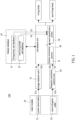
- the living body radar system 100 comprises an image analysis unit 10, a frequency spectrum analysis unit 20, and a calculation unit 30.
- the calculation unit 30 further comprises a feature extraction portion 31 and a match identification portion 32, wherein the match identification portion 32 is electrically connected with a feature database 40.
- the calculation unit 30 applies an artificial intelligence system based on a long short-term memory (LSTM) algorithm for carrying out a feature extraction and comparison determination process.
- LSTM long short-term memory
- the present invention is not limited to such embodiment.
- a radar module 50 is further included, which can transmit and receive an electromagnetic signal whose wavelength fulfils the condition of: 0.001 mm ⁇ ⁇ ⁇ 12mm, preferably 1 mm ⁇ ⁇ ⁇ 10mm, more preferably 3mm ⁇ ⁇ ⁇ 5mm.
- the radar module 50 comprises a point cloud radar 51 and a micro-Doppler radar 52.
- the point cloud radar 51 detects a target object to produce a first signal S1A
- the micro-Doppler radar 52 detects the same target object to produce a second signal S1B.
- the living body identification method 200 applied by the living body radar system 100 is illustrated in Fig. 3 .
- the image analysis unit 10 receives the signal S1 A and processes the signal S1A to produce a plurality of sample points P, so as to form an image signal S2.
- the frequency spectrum analysis unit 20 receives the signal S1 B and processes the signal S1B to produce a frequency spectrum signal S3.
- the feature extraction portion 31 receives the image signal S2 and the frequency spectrum signal S3 and carries out a feature extraction operation, thereby acquiring a target feature F1 of the target object, after which the match identification portion 32 carries out a comparison on the target feature F1, so as to identify if the target object is a living body.
- the radar module 50 is not limited to the two radars as the point cloud radar 51 and the micro-Doppler radar 52 in the embodiment.
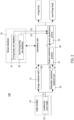
- the radar module 50 is allowed to be a single continuous wave radar 53 (as shown by Fig. 2 ), wherein the continuous wave radar 53 can transmit and receive an electromagnetic signal whose wavelength fulfils the condition of: 0.001 mm ⁇ ⁇ ⁇ 10 mm, preferably 1 mm ⁇ ⁇ ⁇ 10 mm, more preferably 3 mm ⁇ ⁇ ⁇ 5 mm.
- the continuous wave radar 52 detects a target object to produce a signal S1, and the signal S1 is analyzed by the image analysis unit 10 and the frequency spectrum analysis unit 20 to form the aforementioned image signal S2 and frequency spectrum signal S3, respectively, after which the feature extraction portion 31 carries out the feature extraction operation as well.
- the feature database 40 stores the comparison feature F2 corresponding to a living body.
- the match identification portion 32 accesses the comparison feature F2 and accordingly compares the target feature F1 with the comparison feature F2.
- Fig. 4 illustrates a feature database establishment method 300 of the living body radar system 100, which optionally can be applied within the context of the present disclosure, but is not part of the invention as defined by the appended claims.
- the method 300 applies the radar module 50 to detect a target object.
- the point cloud radar 51 is applied for detecting the target object to acquire an image sample signal S4
- the micro-Doppler radar 52 is applied for detecting the target object to acquire a frequency spectrum sample signal S5.
- the feature extraction portion 31 receives the image sample signal S4 and the frequency spectrum sample signal S5 and carries out the features extraction operation to acquire a comparison feature. If the comparison feature is identified as a living body feature, the comparison feature is added into the feature database 40 and categorized as the comparison feature F2 of living body. If the comparison feature is identified as a non-living body feature, the comparison feature is added into the feature database 40 and categorized as the comparison feature F3 of non-living body.
- the feature database 40 comprises a living body sub-database 41, which stores the comparison features F2 that are categorized as living body and to be applied as the standard for the match identification portion 32 to identify a living body. Further, the feature database 40 comprises a non-living body sub-database 42, which stores the comparison features F3 that are categorized as non-living body and to be applied as the standard for the match identification portion 32 to exclude the target object from a living body.
- the non-living body in the embodiment mainly refers to any objects that are not movable, such as a tree or a wire pole.
- the image signal S2 is compared with the lower limbs motion of a walking human body in the image sample signal S4, and the frequency spectrum signal S3 is compared with the lower limbs motion and the body motion of a walking human body in the frequency spectrum sample signal S5.
- the target object is a non-living body (such as a tree or a wire pole)
- the profile of the aforementioned lower limbs and body are taken for differentiating a non-living body and a pedestrian.
- the radar module 50 detects a target object which is a tree
- the point cloud radar 51 produces a first signal S1A
- the micro-Doppler radar 52 produces a second signal S1B
- the image analysis unit 10 receives and processes the signal S1 A to produces the image signal S2, wherein the multiple sample points P of the image signal S2 are illustrated in Fig. 5 , which comprises the sample points P presented as an obvious straight body portion and a scattering portion on the top of the body portion.
- the straight body portion does not present any lower limbs movement and remains stationary, with only slow movement of the scattering sample points P being shown on the top of the straight body.
- the frequency spectrum analysis unit 20 receives and processes the signal S1B to produce the frequency spectrum signal, which is shown as the waveform diagram presenting a mild wave steepness in Fig. 6 . Therefore, the target feature F1 of the target object acquired by the feature extraction portion 31 from the image signal S2 and the frequency spectrum signal S3 is compared with the comparison feature F2, so as to determine that the target object having the target feature F1 is not a living body as a pedestrian or animal. After a further comparison with the comparison feature F3, the target object is deemed as a non-living body according to the image signal S2 and the frequency spectrum signal S3 of the target feature.
- the image analysis unit 10 receives and processes the signal S1A to produces the image signal S2, wherein the multiple sample points P of the image signal S2 are illustrated in Fig. 7 , which comprises an obviously lower transverse body portion and lower limbs-alike sample points P on the bottom of the transverse body portion. According to the dynamic change of the sample points P, the lower limbs portion presents an alternate movement of four legs. Also, the frequency spectrum analysis unit 20 receives and process the signal S1B to produce the frequency spectrum signal S3, which is shown as the waveform diagram in Fig. 8 .
- the waveform representing the transverse portion and the waveform representing the lower limbs have obvious random waveform at the wave crest and the wave trough. Therefore, the target feature F1 of the target object acquired by the feature extraction portion 31 from the image signal S2 and the frequency spectrum signal S3 is compared with the comparison feature F2, so as to determine that the target object having the target feature F1 is a living body. Furthermore, features of the image signal S2 and the frequency spectrum signal S3 can also be applied for determining that the target object is a dog.
- the image analysis unit 10 receives and processes the signal S1A to produces the image signal S2, wherein the multiple sample points P of the image signal S2 are illustrated in Fig. 9 , which comprises a straight body portion and lower limbs and upper limbs-alike sample points P on the straight body portion. According to the dynamic change of the sample points P, a regular movement of the lower limbs portion is obviously shown. Also, the frequency spectrum analysis unit 20 receives and process the signal S1B to produce the frequency spectrum signal S3, which is shown as the waveform diagram in Fig. 10 . The waveforms representing the straight body portion and the lower limbs are distributed in a regular sinusoidal distribution, respectively.
- the target feature F1 of the target object acquired by the feature extraction portion 31 from the image signal S2 and the frequency spectrum signal S3 is compared with the comparison feature F2, so as to determine that the target object having the target feature F1 is a living body. Furthermore, features of the image signal S2 and the frequency spectrum signal S3 can also be applied for determining that the target object is a pedestrian. For further illustration, to further identify if the target object is a pedestrian, in the aforementioned examples in which the target object might be a tree, dog, or pedestrian, features of each target object are obvious for facilitating an accurate identification.
- the result of feature extraction by the feature extraction unit 31 and subsequent comparison by the match identification portion 32 is able to accurately determine that the target object is a pedestrian or not.
- the image signal S2 or frequency spectrum signal S3 may possibly cause a tree or a dog to present a performance which is similar to that of the a pedestrian, thereby leading to a misidentification.
- the frequency spectrum signal S3 acquired may have a performance difficult to be identified.
- the image signal S2 in this case the image of the tree has an obvious body portion and scattering sample points distributed on the top of the body portion, and the lower limbs portion is presented with only one continuous point area, which is different from the performance of a person's lower limbs having two obvious leg portions. Therefore, it is able to accurately identify that the target object is not a pedestrian based on the image signal S2.
- the performance of the image signal S2 is similar to a pedestrian walking with two legs, wherein only two legs are clearly identified, or even only a continuous point area due to the overly closed lower limbs. As a result, it is unable to clearly identify the four legs of a dog. Also, a dog usually has a height similar to a human child, so that it is unable to identify if such target object is a pedestrian through the image signal S2. However, through the performance of the frequency spectrum signal S3, it is allowed to clearly identify that the time period and shape of the four waving limbs are different from that of a pedestrian.
- the target object can be accurately identified to be a non-pedestrian according to the frequency spectrum signal S3.
- the calculation unit 30 to receive the image signal S2 and the frequency spectrum signal S3, the feature extraction operation of the feature extraction portion 31, and the comparing operation of the match identification portion 32, a supplementary identification result is achieved, thereby greatly reducing the possibility of misidentification.
- the calculation unit 30 carries out the feature extraction operation on the image signal S2 and the frequency spectrum signal S3, respectively, the target object is efficiently and accurately identified as being a living body or not.
- the present invention can confirm the target features without the need of a complicated algorithm. Also, the issue of the camera misidentifying the image due to insufficient light during image capturing process is prevented.
- the match identification portion 32 When carrying out a comparison on the target feature, the match identification portion 32 applies the comparison feature F2 which is categorized as a living body in the feature database 40 as a standard of comparison, so as to accordingly identify if the target object is a living body. Also, the feature database 40 is able to be continuously add the comparison features F2 of a living body into the living body sub-database 42, realizing a deep depth learning of artificial intelligence, so that when the match identification portion 32 carries out the comparison on the target feature F1, sufficient comparison samples can be taken as references, thereby improving the identification accuracy.
- the image analysis unit 10 and the frequency spectrum analysis unit 20 are able to form the image signal S2 and the frequency spectrum signal S3, respectively, for facilitating the feature extraction operation of the feature extraction portion 31. Therefore, the volume of components and the cost of radar equipment are reduced.
Landscapes
- Engineering & Computer Science (AREA)
- Remote Sensing (AREA)
- Radar, Positioning & Navigation (AREA)
- Physics & Mathematics (AREA)
- Computer Networks & Wireless Communication (AREA)
- General Physics & Mathematics (AREA)
- Electromagnetism (AREA)
- Radar Systems Or Details Thereof (AREA)
- Burglar Alarm Systems (AREA)
- Geophysics And Detection Of Objects (AREA)
Description
- The present invention relates to living body detection techniques, and more particularly, to a living body radar system, living body identification method, and feature database establishment method.
- An advanced driver assistance systems (ADAS) is a main target of development in related industries. Concerning an assistant driver and automatic driving technique of any stage, the most important is to effectively determine an emergency and conduct corresponding actions. Among other things, the most crucial one is to correctly identify the living body, such as a pedestrian, which is met during the movement of vehicle, so as to carry out an immediate reaction when facing risk of collision. However, during the movement of vehicle, the time for identifying a pedestrian and conducting an appropriate reaction is relatively short, and the driver must rely on the determination of system. Therefore, an accurate and efficient determination module is desirable for meeting a driving safety demand upon an advanced driver assistance system. Thus, how to quickly and correctly determine that there are living bodies such as pedestrians or animals in front of the driver during driving, and to make timely braking or dodge response actions to avoid threating the living bodies, is a crucial target for the development of advanced driving assistance system technology.
- According to existing detection technology for obstacles identification, such as radar technology, the radio wave information thereby generated can only detect the location and distance of the obstacle, and is unable to show the image of the living body, so that it is difficult to identify if the obstacle is a living body, especially a pedestrian. Regarding the identification method of image capturing, although it is able to identify the obstacle as a living body, but the issues of failing to accurately identify the moving speed and distance of the living body remain unsolved.
- Accordingly,
US10354160B2 - Further prior disclosures which are relevant to the invention, in particular to the field of living body detection techniques by radar detection, are patent documents
DE 10 2018 203591 B3 ,US20180348343A1 ,DE102016215102.9A , andUS20110304498A1 . Also relevant to the technical field of the invention are the scientific articles "Multiple joint-variable domains recognition of human motion" (Jokanovic Branka et al., (2017), IEEE Radar Conference), and "A Survey of Deep Learning-Based Human Activity Recognition in Radar" (Xinyu Li et al., (2019), Remote Sensing, Molecular Diversity Preservation International (MDPI), vol. 11, no. 9, page 1068). - To improve the issues above, the present invention discloses a living body radar system and an identification method as defined by the appended claims. An image analysis and frequency spectrum analysis are applied as the main detection techniques for identifying if the target object is a living body.
- For achieving the aforementioned objectives, living body radar system and identification method thereof are provided. The system comprise an image analysis unit, a frequency spectrum analysis unit, and a calculation unit electrically connected with the image analysis unit and the frequency spectrum analysis unit. The calculation unit comprises a feature extraction portion and a match identification portion. The image analysis unit receives a signal detected by a radar and signally processes the signal to produce a plurality of sample points for forming an image signal. The frequency spectrum analysis unit receives the signal and signally processes the signal to produce a frequency spectrum signal. The feature extraction portion receives the image signal and the frequency spectrum signal for feature extraction, thereby acquiring a target feature of a target object. The match identification portion conducts a comparison on the target feature, so as to identify if the target object is a living body.
- With such configuration, during a movement of a target object, the feature extraction portion receives the image signal and the frequency spectrum signal for feature extraction to acquire the target feature, and the match identification portion conducts a comparison on the target feature, such that the two phenomena are integrated in a complementary manner for identifying the true movement model of the target object, thereby resolving the issue of possible image misidentification due to light interference during image capturing process of a conventional camera, and accurately identifying if the target object is a living body.
- A feature database establishment method is not according to the invention and is presented for illustration purpose only, said method, which collects a radar signal of a living body, comprises the steps of receiving the signal with the image analysis unit and signally processing the signal to produce a plurality of sample points for forming an image sample signal, and also receiving the signal with the frequency spectrum analysis unit and signally processing the signal to produce a frequency spectrum sample signal; conducting feature extraction on the image sample signal and the frequency spectrum sample signal with the feature extraction portion to acquire a comparison feature; and establishing the comparison feature in a feature database and categorizing it as the comparison feature of the living body.
- With the establishment of the feature database, the comparison features categorized as the living body are taken as the standard for feature comparison of the target feature by the match identification portion, so as to accordingly identify if the target object is a living body. Also, the feature database is allowed to be continuously added with different comparison features that are categorized as a living body. By expanding the feature database with different comparison features, when identifying if the target object is a living body, the living body radar system achieves a deep-depth learning with artificial intelligence. Therefore, sufficient comparison samples are taken as reference for comparison of target features by the match identification portion, thereby assuring a high accuracy for identifying if the target object is a living body.
-
-
Fig. 1 is a block diagram of the living body radar system in accordance with an embodiment of the present invention. -
Fig. 2 is another block diagram of the living body radar system in accordance with an embodiment of the present invention. -
Fig. 3 is a flow chart of the living body identification method in accordance with an embodiment of the present invention. -
Fig. 4 is a flow chart of the database establishment method in accordance with an embodiment of the present invention. -
Fig. 5 is a sample point distribution diagram presented by the image signal when the target object is a tree. -
Fig. 6 is a waveform diagram presented by the frequency spectrum signal when the target object is a tree. -
Fig. 7 is a sample point distribution diagram presented by the image signal when the target object is a dog. -
Fig. 8 is a waveform diagram presented by the frequency spectrum signal when the target object is a dog. -
Fig. 9 is a sample point distribution diagram presented by the image signal when the target object is a pedestrian. -
Fig. 10 is a waveform diagram presented by the frequency spectrum signal when the target object is a pedestrian. - Embodiments of the present invention are illustrated in detail along with the drawings. However, the technical features included by the present invention are not limited to certain embodiments hereby provided. Scope of the present invention shall be referred to the claims, which include all the possible replacements, modifications, and equivalent features.
- Referring to
Fig. 1 to Fig. 10 , the present invention provides a livingbody radar system 100, and a livingbody identification method 200. - The living
body radar system 100, as shown by the embodiment ofFig. 1 , comprises animage analysis unit 10, a frequencyspectrum analysis unit 20, and acalculation unit 30. Thecalculation unit 30 further comprises afeature extraction portion 31 and amatch identification portion 32, wherein thematch identification portion 32 is electrically connected with afeature database 40. In the embodiment, thecalculation unit 30 applies an artificial intelligence system based on a long short-term memory (LSTM) algorithm for carrying out a feature extraction and comparison determination process. However, the present invention is not limited to such embodiment. - In the embodiment, a
radar module 50 is further included, which can transmit and receive an electromagnetic signal whose wavelength fulfils the condition of: 0.001 mm < λ ≤ 12mm, preferably 1 mm < λ ≤ 10mm, more preferably 3mm < λ ≤ 5mm. Theradar module 50 comprises apoint cloud radar 51 and amicro-Doppler radar 52. Thepoint cloud radar 51 detects a target object to produce a first signal S1A, and themicro-Doppler radar 52 detects the same target object to produce a second signal S1B. - The living
body identification method 200 applied by the livingbody radar system 100 is illustrated inFig. 3 . In the embodiment, theimage analysis unit 10 receives the signal S1A and processes the signal S1A to produce a plurality of sample points P, so as to form an image signal S2. Also, the frequencyspectrum analysis unit 20 receives the signal S1B and processes the signal S1B to produce a frequency spectrum signal S3. Then, thefeature extraction portion 31 receives the image signal S2 and the frequency spectrum signal S3 and carries out a feature extraction operation, thereby acquiring a target feature F1 of the target object, after which thematch identification portion 32 carries out a comparison on the target feature F1, so as to identify if the target object is a living body. - The
radar module 50 is not limited to the two radars as thepoint cloud radar 51 and themicro-Doppler radar 52 in the embodiment. In different embodiments, theradar module 50 is allowed to be a single continuous wave radar 53 (as shown byFig. 2 ), wherein thecontinuous wave radar 53 can transmit and receive an electromagnetic signal whose wavelength fulfils the condition of: 0.001 mm < λ ≤ 10 mm, preferably 1 mm < λ ≤ 10 mm, more preferably 3 mm < λ ≤ 5 mm. Thecontinuous wave radar 52 detects a target object to produce a signal S1, and the signal S1 is analyzed by theimage analysis unit 10 and the frequencyspectrum analysis unit 20 to form the aforementioned image signal S2 and frequency spectrum signal S3, respectively, after which thefeature extraction portion 31 carries out the feature extraction operation as well. - The
feature database 40 stores the comparison feature F2 corresponding to a living body. When thematch identification portion 32 carries out the comparison on the target feature F1, thematch identification portion 32 accesses the comparison feature F2 and accordingly compares the target feature F1 with the comparison feature F2. -
Fig. 4 illustrates a featuredatabase establishment method 300 of the livingbody radar system 100, which optionally can be applied within the context of the present disclosure, but is not part of the invention as defined by the appended claims. Themethod 300 applies theradar module 50 to detect a target object. In the embodiment, thepoint cloud radar 51 is applied for detecting the target object to acquire an image sample signal S4, and themicro-Doppler radar 52 is applied for detecting the target object to acquire a frequency spectrum sample signal S5. Then, thefeature extraction portion 31 receives the image sample signal S4 and the frequency spectrum sample signal S5 and carries out the features extraction operation to acquire a comparison feature. If the comparison feature is identified as a living body feature, the comparison feature is added into thefeature database 40 and categorized as the comparison feature F2 of living body. If the comparison feature is identified as a non-living body feature, the comparison feature is added into thefeature database 40 and categorized as the comparison feature F3 of non-living body. - In a preferable embodiment, the
feature database 40 comprises a living body sub-database 41, which stores the comparison features F2 that are categorized as living body and to be applied as the standard for thematch identification portion 32 to identify a living body. Further, thefeature database 40 comprises anon-living body sub-database 42, which stores the comparison features F3 that are categorized as non-living body and to be applied as the standard for thematch identification portion 32 to exclude the target object from a living body. The non-living body in the embodiment mainly refers to any objects that are not movable, such as a tree or a wire pole. - In the living
body identification method 200 in the embodiment, taking a pedestrian as an example during the comparison between the comparison feature F2 and the target feature F1, the image signal S2 is compared with the lower limbs motion of a walking human body in the image sample signal S4, and the frequency spectrum signal S3 is compared with the lower limbs motion and the body motion of a walking human body in the frequency spectrum sample signal S5. Or, when the target object is a non-living body (such as a tree or a wire pole), the profile of the aforementioned lower limbs and body are taken for differentiating a non-living body and a pedestrian. - Application of the living
body radar system 100 and the livingbody identification method 200 in the present invention for identifying a target object during a vehicle movement process are illustrated as follows - During the movement of vehicle having the aforementioned living
body radar system 100 on the road, in an embodiment, when theradar module 50 detects a target object which is a tree, thepoint cloud radar 51 produces a first signal S1A, themicro-Doppler radar 52 produces a second signal S1B, and theimage analysis unit 10 receives and processes the signal S1A to produces the image signal S2, wherein the multiple sample points P of the image signal S2 are illustrated inFig. 5 , which comprises the sample points P presented as an obvious straight body portion and a scattering portion on the top of the body portion. According to the dynamic change of the sample points P, the straight body portion does not present any lower limbs movement and remains stationary, with only slow movement of the scattering sample points P being shown on the top of the straight body. Also, the frequencyspectrum analysis unit 20 receives and processes the signal S1B to produce the frequency spectrum signal, which is shown as the waveform diagram presenting a mild wave steepness inFig. 6 . Therefore, the target feature F1 of the target object acquired by thefeature extraction portion 31 from the image signal S2 and the frequency spectrum signal S3 is compared with the comparison feature F2, so as to determine that the target object having the target feature F1 is not a living body as a pedestrian or animal. After a further comparison with the comparison feature F3, the target object is deemed as a non-living body according to the image signal S2 and the frequency spectrum signal S3 of the target feature. - In another embodiment in which the
radar module 50 detects the target object which is a dog, theimage analysis unit 10 receives and processes the signal S1A to produces the image signal S2, wherein the multiple sample points P of the image signal S2 are illustrated inFig. 7 , which comprises an obviously lower transverse body portion and lower limbs-alike sample points P on the bottom of the transverse body portion. According to the dynamic change of the sample points P, the lower limbs portion presents an alternate movement of four legs. Also, the frequencyspectrum analysis unit 20 receives and process the signal S1B to produce the frequency spectrum signal S3, which is shown as the waveform diagram inFig. 8 . The waveform representing the transverse portion and the waveform representing the lower limbs have obvious random waveform at the wave crest and the wave trough. Therefore, the target feature F1 of the target object acquired by thefeature extraction portion 31 from the image signal S2 and the frequency spectrum signal S3 is compared with the comparison feature F2, so as to determine that the target object having the target feature F1 is a living body. Furthermore, features of the image signal S2 and the frequency spectrum signal S3 can also be applied for determining that the target object is a dog. - In still another embodiment in which the
radar module 50 detects the target object which is a pedestrian, theimage analysis unit 10 receives and processes the signal S1A to produces the image signal S2, wherein the multiple sample points P of the image signal S2 are illustrated inFig. 9 , which comprises a straight body portion and lower limbs and upper limbs-alike sample points P on the straight body portion. According to the dynamic change of the sample points P, a regular movement of the lower limbs portion is obviously shown. Also, the frequencyspectrum analysis unit 20 receives and process the signal S1B to produce the frequency spectrum signal S3, which is shown as the waveform diagram inFig. 10 . The waveforms representing the straight body portion and the lower limbs are distributed in a regular sinusoidal distribution, respectively. Therefore, the target feature F1 of the target object acquired by thefeature extraction portion 31 from the image signal S2 and the frequency spectrum signal S3 is compared with the comparison feature F2, so as to determine that the target object having the target feature F1 is a living body. Furthermore, features of the image signal S2 and the frequency spectrum signal S3 can also be applied for determining that the target object is a pedestrian. For further illustration, to further identify if the target object is a pedestrian, in the aforementioned examples in which the target object might be a tree, dog, or pedestrian, features of each target object are obvious for facilitating an accurate identification. More specifically, regardless of the image signal S2 or the frequency spectrum signal S3, the result of feature extraction by thefeature extraction unit 31 and subsequent comparison by thematch identification portion 32 is able to accurately determine that the target object is a pedestrian or not. However, in certain cases, the image signal S2 or frequency spectrum signal S3 may possibly cause a tree or a dog to present a performance which is similar to that of the a pedestrian, thereby leading to a misidentification. - For example, when a tree is blown by wind, its trunk may slightly wave, and its branches may wave in a larger scale. Such performance is similar to the motion of a slowing moving pedestrian, wherein the body slightly waves and the limbs wave in a larger scale. As a result, the frequency spectrum signal S3 acquired may have a performance difficult to be identified. However, as for the image signal S2 in this case, the image of the tree has an obvious body portion and scattering sample points distributed on the top of the body portion, and the lower limbs portion is presented with only one continuous point area, which is different from the performance of a person's lower limbs having two obvious leg portions. Therefore, it is able to accurately identify that the target object is not a pedestrian based on the image signal S2.
- Regarding the identification mechanism for a dog, when a dog slowly move toward or away from a vehicle, the performance of the image signal S2 is similar to a pedestrian walking with two legs, wherein only two legs are clearly identified, or even only a continuous point area due to the overly closed lower limbs. As a result, it is unable to clearly identify the four legs of a dog. Also, a dog usually has a height similar to a human child, so that it is unable to identify if such target object is a pedestrian through the image signal S2. However, through the performance of the frequency spectrum signal S3, it is allowed to clearly identify that the time period and shape of the four waving limbs are different from that of a pedestrian. Therefore, the target object can be accurately identified to be a non-pedestrian according to the frequency spectrum signal S3. Thus, by applying the
calculation unit 30 to receive the image signal S2 and the frequency spectrum signal S3, the feature extraction operation of thefeature extraction portion 31, and the comparing operation of thematch identification portion 32, a supplementary identification result is achieved, thereby greatly reducing the possibility of misidentification. - With the foregoing configuration, functions and effects of the present invention will be illustrated below.
- The
calculation unit 30 carries out the feature extraction operation on the image signal S2 and the frequency spectrum signal S3, respectively, the target object is efficiently and accurately identified as being a living body or not. Compared with conventional arts for identifying a pedestrian's image, the present invention can confirm the target features without the need of a complicated algorithm. Also, the issue of the camera misidentifying the image due to insufficient light during image capturing process is prevented. - When carrying out a comparison on the target feature, the
match identification portion 32 applies the comparison feature F2 which is categorized as a living body in thefeature database 40 as a standard of comparison, so as to accordingly identify if the target object is a living body. Also, thefeature database 40 is able to be continuously add the comparison features F2 of a living body into the living body sub-database 42, realizing a deep depth learning of artificial intelligence, so that when thematch identification portion 32 carries out the comparison on the target feature F1, sufficient comparison samples can be taken as references, thereby improving the identification accuracy. - By using the signal S1 generated by a single
continuous wave radar 53, theimage analysis unit 10 and the frequencyspectrum analysis unit 20 are able to form the image signal S2 and the frequency spectrum signal S3, respectively, for facilitating the feature extraction operation of thefeature extraction portion 31. Therefore, the volume of components and the cost of radar equipment are reduced. - The invention is not to be limited except as by the appended claims.
Claims (8)
- A living body radar system (100), comprising:an image analysis unit (10) for receiving a signal (S1) detected by a radar and signally processing the signal (S1) to produce a plurality of sample points to form an image signal (S2);a frequency spectrum analysis unit (20) for receiving the signal (S1) and signally processing the signal (S1) to produce a frequency spectrum signal (S3); anda calculation unit (30) electrically connected with the image analysis unit (10) and the frequency spectrum analysis unit (20), the calculation unit (30) comprising a feature extraction portion (31) and a match identification portion (32), the feature extraction portion (31) receiving the image signal (S2) and the frequency spectrum signal (S3) and carrying out a feature extraction operation to acquire a target feature (F1) of a target object, the match identification portion (32) carrying out a comparison operation on the target feature (F1),wherein the match identification portion (32) is electrically connected with a feature database (40); the feature database (40) stores a comparison feature (F2/F3) of a living body; when the match identification portion (32) carries out the comparison operation on the target feature (F1), the match identification (32) accesses the comparison feature (F2/F3) and compares the target feature (F1) with the comparison feature (F2/F3),wherein the comparison feature (F2/F3) is acquired by the feature extraction operation on an image sample signal (S4) and a frequency spectrum sample signal (S5) that are acquired by the radar detecting a living body,characterized in thatthe living body is a human body; when the comparison feature (F2/F3) is compared with the target feature (F1), the image signal (S2) is compared with a lower limbs motion of the human body in the image sample signal (S4), and the frequency spectrum signal (S3) is compared with the lower limbs motion and a body motion of the human body in the frequency spectrum sample signal (S5).
- The radar system (100) of claim 1, wherein the calculation unit (30) applies an artificial intelligence system based on a long short-term memory (LSTM) algorithm for carrying out the feature extraction and comparison processes.
- The radar system (100) of claim 1, further comprising a radar module (50) for detecting the target object to produce the signal (S1).
- The radar system (100) of claim 3, wherein the radar module (50) comprise a point cloud radar (51) and a micro-Doppler radar (52); a signal produced by the point cloud radar (51) is applied for the image analysis unit (10) to form the image signal (S2), and a signal produced by the micro-Doppler radar (52) is applied for the frequency spectrum analysis unit (20) to produce the frequency spectrum signal (S3).
- The radar system (100) of claim 3, wherein the radar module (50) comprises a continuous wave radar (53), a signal produced by the continuous wave radar (53) is applied for the image analysis unit (10) and the frequency analysis unit (20) to form the image signal (S2) and the frequency spectrum signal (S3), respectively.
- A living body identification method (200) of a living body radar system (100), comprising:receiving, by an image analysis unit (10), a signal (S1) detected by a radar and signally processing the signal (S1) to produces a plurality of sample points to form an image signal (S2);receiving, by a frequency spectrum analysis unit (20), the signal (S1) and signally processing the signal (S1) to produce a frequency spectrum signal (S3);receiving, by a feature extraction portion (31), the image signal (S2) and the frequency spectrum signal (S3) and carrying out a feature extraction operation to acquire a target feature (F1) of a target object; andcarrying out, by a match identification portion (32), a comparison operation on the target feature (F1) to identify if the target object is a living body,wherein when the match identification portion (32) carries out the comparison operation on the target feature (F1), the match identification (32) accesses a comparison feature (F2) and compares the target feature (F1) with the comparison feature (F2),wherein the comparison feature (F2) is acquired by the feature extraction operation on an image sample signal (S4) and a frequency spectrum sample signal (S5) that are acquired by the radar detecting a living body,characterized in that the living body is a human body; when the comparison feature (F2) is compared with the target feature (F1), the image signal (S2) is compared with a lower limbs motion of the human body in the image sample signal (S4), and the frequency spectrum signal (S3) is compared with the lower limbs motion and a body motion of the human body in the frequency spectrum sample signal (S5).
- The identification method (200) of claim 6, wherein the comparison feature (F2) is established in a feature database (40) and categorized as the comparison feature (F2) of a living body and applied as a standard for the match identification portion (32) to identify the target object as the living body.
- The identification method (200) of claim 7, wherein the feature database (40) comprises a living body sub-database (41) and a non-living body sub-database (42); the comparison feature (F2) categorized as a living body is stored in the living body sub-database (41); the non-living body sub-database (42) stores a comparison feature (F3) categorized as a non-living body and applied as a standard for the match identification portion (32) exclude the target object from a living body.
Applications Claiming Priority (1)
| Application Number | Priority Date | Filing Date | Title |
|---|---|---|---|
| TW109101432A TWI809241B (en) | 2020-01-16 | 2020-01-16 | Life form radar system, identification method, and database establishment method |
Publications (3)
| Publication Number | Publication Date |
|---|---|
| EP3851871A1 EP3851871A1 (en) | 2021-07-21 |
| EP3851871B1 true EP3851871B1 (en) | 2024-04-17 |
| EP3851871C0 EP3851871C0 (en) | 2024-04-17 |
Family
ID=74186524
Family Applications (1)
| Application Number | Title | Priority Date | Filing Date |
|---|---|---|---|
| EP21151888.1A Active EP3851871B1 (en) | 2020-01-16 | 2021-01-15 | Living body radar system, identification method, and feature database establishment method |
Country Status (3)
| Country | Link |
|---|---|
| EP (1) | EP3851871B1 (en) |
| CN (1) | CN113138386B (en) |
| TW (1) | TWI809241B (en) |
Families Citing this family (2)
| Publication number | Priority date | Publication date | Assignee | Title |
|---|---|---|---|---|
| CN114997244B (en) * | 2022-07-19 | 2022-10-28 | 亿慧云智能科技(深圳)股份有限公司 | Radar signal characteristic identification management system and method based on artificial intelligence |
| WO2025144061A1 (en) * | 2023-12-29 | 2025-07-03 | Owl Sentry Sp. Z O. O. | A radar monitoring station for animal migration |
Citations (1)
| Publication number | Priority date | Publication date | Assignee | Title |
|---|---|---|---|---|
| DE102018203591B3 (en) * | 2018-03-09 | 2019-07-04 | Conti Temic Microelectronic Gmbh | Method and system for classifying road users |
Family Cites Families (13)
| Publication number | Priority date | Publication date | Assignee | Title |
|---|---|---|---|---|
| EP2315051A1 (en) * | 2009-10-22 | 2011-04-27 | Toyota Motor Europe NV | Submillimeter radar using phase information |
| TWI466657B (en) * | 2010-12-24 | 2015-01-01 | 財團法人工業技術研究院 | Method for measuring physiological parameters of human body |
| TWI458653B (en) * | 2011-10-25 | 2014-11-01 | Altek Autotronics Corp | Blind spot detection system and blind spot detection method thereof |
| PT2804014E (en) * | 2013-05-13 | 2015-09-10 | Kapsch Trafficcom Ag | Device and method for determining a characteristic of a vehicle |
| JP6256239B2 (en) | 2014-07-25 | 2018-01-10 | 株式会社デンソー | Pedestrian detection device and pedestrian detection method |
| JP6226084B2 (en) * | 2014-11-19 | 2017-11-08 | 三菱電機株式会社 | Radar equipment |
| CN104468001B (en) * | 2014-11-26 | 2017-04-19 | 北京邮电大学 | Signal identification method and system based on radio signal frequency spectrum feature template |
| CN105488855A (en) * | 2015-11-24 | 2016-04-13 | 东南大学 | Vehicle type identification method in ETC system and ETC system |
| DE102016215102A1 (en) * | 2016-08-12 | 2017-12-07 | Conti Temic Microelectronic Gmbh | Pedestrian detection by radar |
| TWI753023B (en) * | 2016-10-04 | 2022-01-21 | 加拿大商艾維吉隆股份有限公司 | Computer-implemented method for detecting a person in publicly accessible location, method for controlling loitering in unsecured location, and physical security system |
| US10942256B2 (en) * | 2017-06-05 | 2021-03-09 | Metawave Corporation | Intelligent metamaterial radar for target identification |
| CN108957445B (en) * | 2018-07-30 | 2020-08-25 | 四川九洲空管科技有限责任公司 | Low-altitude low-speed small target detection method |
| CN109298415B (en) * | 2018-11-20 | 2020-09-22 | 中车株洲电力机车有限公司 | Method for detecting obstacles on track and road |
-
2020
- 2020-01-16 TW TW109101432A patent/TWI809241B/en active
- 2020-12-09 CN CN202011427075.XA patent/CN113138386B/en active Active
-
2021
- 2021-01-15 EP EP21151888.1A patent/EP3851871B1/en active Active
Patent Citations (1)
| Publication number | Priority date | Publication date | Assignee | Title |
|---|---|---|---|---|
| DE102018203591B3 (en) * | 2018-03-09 | 2019-07-04 | Conti Temic Microelectronic Gmbh | Method and system for classifying road users |
Also Published As
| Publication number | Publication date |
|---|---|
| EP3851871A1 (en) | 2021-07-21 |
| CN113138386A (en) | 2021-07-20 |
| EP3851871C0 (en) | 2024-04-17 |
| CN113138386B (en) | 2024-12-24 |
| TW202129595A (en) | 2021-08-01 |
| TWI809241B (en) | 2023-07-21 |
Similar Documents
| Publication | Publication Date | Title |
|---|---|---|
| US11043005B2 (en) | Lidar-based multi-person pose estimation | |
| CN107609522B (en) | An information fusion vehicle detection system based on lidar and machine vision | |
| KR101912453B1 (en) | Apparatus And Method Detectinc Obstacle And Alerting Collision | |
| CN109633685A (en) | A kind of method and system based on laser radar obstruction detection state | |
| WO2011067790A2 (en) | Cost-effective system and method for detecting, classifying and tracking the pedestrian using near infrared camera | |
| Jin et al. | Cross-modal supervision-based multitask learning with automotive radar raw data | |
| CN110717918B (en) | Pedestrian detection method and device | |
| CN113313182B (en) | Target identification method and terminal based on radar and video fusion | |
| CN116148801B (en) | Millimeter wave radar-based target detection method and system | |
| CN114814832A (en) | Millimeter wave radar-based real-time monitoring system and method for human body falling behavior | |
| EP3851871A1 (en) | Living body radar system, identification method, and feature database establishment method | |
| CN111406224A (en) | A target reliability determination method, a target identification method, system, vehicle and storage medium | |
| JP2005311691A (en) | Object detection apparatus and method | |
| EP3845926A1 (en) | Multi-spectral lidar object tracking method and system | |
| CN113687348A (en) | Pedestrian identification method and device based on tracking micro-Doppler image | |
| Yang et al. | On-road collision warning based on multiple FOE segmentation using a dashboard camera | |
| KR20190050551A (en) | Apparatus and method for recognizing body motion based on depth map information | |
| KR20200101514A (en) | Object Detection System Using Deep Learning | |
| Vu et al. | Vehicle detection, tracking and counting in traffic video streams based on the combination of YOLOv9 and DeepSORT algorithms | |
| Domínguez et al. | Multi-objective decision support system for intelligent road signaling | |
| WO2017077261A1 (en) | A monocular camera cognitive imaging system for a vehicle | |
| Grimm et al. | Discrimination of stationary from moving targets with recurrent neural networks in automotive radar | |
| Sardjono et al. | Human Motion Change Detection Based On FMCW Radar | |
| Garcia et al. | Computer vision and laser scanner road environment perception | |
| KR101936108B1 (en) | Method and apparatus for detecting traffic sign |
Legal Events
| Date | Code | Title | Description |
|---|---|---|---|
| PUAI | Public reference made under article 153(3) epc to a published international application that has entered the european phase |
Free format text: ORIGINAL CODE: 0009012 |
|
| STAA | Information on the status of an ep patent application or granted ep patent |
Free format text: STATUS: THE APPLICATION HAS BEEN PUBLISHED |
|
| AK | Designated contracting states |
Kind code of ref document: A1 Designated state(s): AL AT BE BG CH CY CZ DE DK EE ES FI FR GB GR HR HU IE IS IT LI LT LU LV MC MK MT NL NO PL PT RO RS SE SI SK SM TR |
|
| STAA | Information on the status of an ep patent application or granted ep patent |
Free format text: STATUS: REQUEST FOR EXAMINATION WAS MADE |
|
| 17P | Request for examination filed |
Effective date: 20220121 |
|
| RBV | Designated contracting states (corrected) |
Designated state(s): AL AT BE BG CH CY CZ DE DK EE ES FI FR GB GR HR HU IE IS IT LI LT LU LV MC MK MT NL NO PL PT RO RS SE SI SK SM TR |
|
| STAA | Information on the status of an ep patent application or granted ep patent |
Free format text: STATUS: EXAMINATION IS IN PROGRESS |
|
| 17Q | First examination report despatched |
Effective date: 20230227 |
|
| GRAP | Despatch of communication of intention to grant a patent |
Free format text: ORIGINAL CODE: EPIDOSNIGR1 |
|
| STAA | Information on the status of an ep patent application or granted ep patent |
Free format text: STATUS: GRANT OF PATENT IS INTENDED |
|
| INTG | Intention to grant announced |
Effective date: 20231127 |
|
| RIN1 | Information on inventor provided before grant (corrected) |
Inventor name: HSU, CHUN-JIE Inventor name: WANG, HSIAO-NING Inventor name: CHEN, CHENG-FOO Inventor name: YU, SAN-CHUAN |
|
| GRAS | Grant fee paid |
Free format text: ORIGINAL CODE: EPIDOSNIGR3 |
|
| GRAA | (expected) grant |
Free format text: ORIGINAL CODE: 0009210 |
|
| STAA | Information on the status of an ep patent application or granted ep patent |
Free format text: STATUS: THE PATENT HAS BEEN GRANTED |
|
| AK | Designated contracting states |
Kind code of ref document: B1 Designated state(s): AL AT BE BG CH CY CZ DE DK EE ES FI FR GB GR HR HU IE IS IT LI LT LU LV MC MK MT NL NO PL PT RO RS SE SI SK SM TR |
|
| REG | Reference to a national code |
Ref country code: GB Ref legal event code: FG4D |
|
| REG | Reference to a national code |
Ref country code: CH Ref legal event code: EP |
|
| REG | Reference to a national code |
Ref country code: DE Ref legal event code: R096 Ref document number: 602021011757 Country of ref document: DE |
|
| REG | Reference to a national code |
Ref country code: IE Ref legal event code: FG4D |
|
| U01 | Request for unitary effect filed |
Effective date: 20240506 |
|
| U07 | Unitary effect registered |
Designated state(s): AT BE BG DE DK EE FI FR IT LT LU LV MT NL PT SE SI Effective date: 20240517 |
|
| PG25 | Lapsed in a contracting state [announced via postgrant information from national office to epo] |
Ref country code: IS Free format text: LAPSE BECAUSE OF FAILURE TO SUBMIT A TRANSLATION OF THE DESCRIPTION OR TO PAY THE FEE WITHIN THE PRESCRIBED TIME-LIMIT Effective date: 20240817 |
|
| PG25 | Lapsed in a contracting state [announced via postgrant information from national office to epo] |
Ref country code: HR Free format text: LAPSE BECAUSE OF FAILURE TO SUBMIT A TRANSLATION OF THE DESCRIPTION OR TO PAY THE FEE WITHIN THE PRESCRIBED TIME-LIMIT Effective date: 20240417 |
|
| PG25 | Lapsed in a contracting state [announced via postgrant information from national office to epo] |
Ref country code: GR Free format text: LAPSE BECAUSE OF FAILURE TO SUBMIT A TRANSLATION OF THE DESCRIPTION OR TO PAY THE FEE WITHIN THE PRESCRIBED TIME-LIMIT Effective date: 20240718 |
|
| PG25 | Lapsed in a contracting state [announced via postgrant information from national office to epo] |
Ref country code: ES Free format text: LAPSE BECAUSE OF FAILURE TO SUBMIT A TRANSLATION OF THE DESCRIPTION OR TO PAY THE FEE WITHIN THE PRESCRIBED TIME-LIMIT Effective date: 20240417 |
|
| PG25 | Lapsed in a contracting state [announced via postgrant information from national office to epo] |
Ref country code: PL Free format text: LAPSE BECAUSE OF FAILURE TO SUBMIT A TRANSLATION OF THE DESCRIPTION OR TO PAY THE FEE WITHIN THE PRESCRIBED TIME-LIMIT Effective date: 20240417 |
|
| PG25 | Lapsed in a contracting state [announced via postgrant information from national office to epo] |
Ref country code: PL Free format text: LAPSE BECAUSE OF FAILURE TO SUBMIT A TRANSLATION OF THE DESCRIPTION OR TO PAY THE FEE WITHIN THE PRESCRIBED TIME-LIMIT Effective date: 20240417 Ref country code: NO Free format text: LAPSE BECAUSE OF FAILURE TO SUBMIT A TRANSLATION OF THE DESCRIPTION OR TO PAY THE FEE WITHIN THE PRESCRIBED TIME-LIMIT Effective date: 20240717 Ref country code: IS Free format text: LAPSE BECAUSE OF FAILURE TO SUBMIT A TRANSLATION OF THE DESCRIPTION OR TO PAY THE FEE WITHIN THE PRESCRIBED TIME-LIMIT Effective date: 20240817 Ref country code: HR Free format text: LAPSE BECAUSE OF FAILURE TO SUBMIT A TRANSLATION OF THE DESCRIPTION OR TO PAY THE FEE WITHIN THE PRESCRIBED TIME-LIMIT Effective date: 20240417 Ref country code: GR Free format text: LAPSE BECAUSE OF FAILURE TO SUBMIT A TRANSLATION OF THE DESCRIPTION OR TO PAY THE FEE WITHIN THE PRESCRIBED TIME-LIMIT Effective date: 20240718 Ref country code: ES Free format text: LAPSE BECAUSE OF FAILURE TO SUBMIT A TRANSLATION OF THE DESCRIPTION OR TO PAY THE FEE WITHIN THE PRESCRIBED TIME-LIMIT Effective date: 20240417 Ref country code: RS Free format text: LAPSE BECAUSE OF FAILURE TO SUBMIT A TRANSLATION OF THE DESCRIPTION OR TO PAY THE FEE WITHIN THE PRESCRIBED TIME-LIMIT Effective date: 20240717 |
|
| REG | Reference to a national code |
Ref country code: DE Ref legal event code: R097 Ref document number: 602021011757 Country of ref document: DE |
|
| PG25 | Lapsed in a contracting state [announced via postgrant information from national office to epo] |
Ref country code: CZ Free format text: LAPSE BECAUSE OF FAILURE TO SUBMIT A TRANSLATION OF THE DESCRIPTION OR TO PAY THE FEE WITHIN THE PRESCRIBED TIME-LIMIT Effective date: 20240417 |
|
| PG25 | Lapsed in a contracting state [announced via postgrant information from national office to epo] |
Ref country code: SK Free format text: LAPSE BECAUSE OF FAILURE TO SUBMIT A TRANSLATION OF THE DESCRIPTION OR TO PAY THE FEE WITHIN THE PRESCRIBED TIME-LIMIT Effective date: 20240417 Ref country code: RO Free format text: LAPSE BECAUSE OF FAILURE TO SUBMIT A TRANSLATION OF THE DESCRIPTION OR TO PAY THE FEE WITHIN THE PRESCRIBED TIME-LIMIT Effective date: 20240417 |
|
| PG25 | Lapsed in a contracting state [announced via postgrant information from national office to epo] |
Ref country code: SM Free format text: LAPSE BECAUSE OF FAILURE TO SUBMIT A TRANSLATION OF THE DESCRIPTION OR TO PAY THE FEE WITHIN THE PRESCRIBED TIME-LIMIT Effective date: 20240417 |
|
| PG25 | Lapsed in a contracting state [announced via postgrant information from national office to epo] |
Ref country code: SM Free format text: LAPSE BECAUSE OF FAILURE TO SUBMIT A TRANSLATION OF THE DESCRIPTION OR TO PAY THE FEE WITHIN THE PRESCRIBED TIME-LIMIT Effective date: 20240417 Ref country code: SK Free format text: LAPSE BECAUSE OF FAILURE TO SUBMIT A TRANSLATION OF THE DESCRIPTION OR TO PAY THE FEE WITHIN THE PRESCRIBED TIME-LIMIT Effective date: 20240417 Ref country code: RO Free format text: LAPSE BECAUSE OF FAILURE TO SUBMIT A TRANSLATION OF THE DESCRIPTION OR TO PAY THE FEE WITHIN THE PRESCRIBED TIME-LIMIT Effective date: 20240417 Ref country code: CZ Free format text: LAPSE BECAUSE OF FAILURE TO SUBMIT A TRANSLATION OF THE DESCRIPTION OR TO PAY THE FEE WITHIN THE PRESCRIBED TIME-LIMIT Effective date: 20240417 |
|
| PLBE | No opposition filed within time limit |
Free format text: ORIGINAL CODE: 0009261 |
|
| STAA | Information on the status of an ep patent application or granted ep patent |
Free format text: STATUS: NO OPPOSITION FILED WITHIN TIME LIMIT |
|
| U20 | Renewal fee for the european patent with unitary effect paid |
Year of fee payment: 5 Effective date: 20250127 |
|
| 26N | No opposition filed |
Effective date: 20250120 |
|
| REG | Reference to a national code |
Ref country code: CH Ref legal event code: PL |
|
| PG25 | Lapsed in a contracting state [announced via postgrant information from national office to epo] |
Ref country code: MC Free format text: LAPSE BECAUSE OF FAILURE TO SUBMIT A TRANSLATION OF THE DESCRIPTION OR TO PAY THE FEE WITHIN THE PRESCRIBED TIME-LIMIT Effective date: 20240417 |
|
| GBPC | Gb: european patent ceased through non-payment of renewal fee |
Effective date: 20250115 |
|
| PG25 | Lapsed in a contracting state [announced via postgrant information from national office to epo] |
Ref country code: GB Free format text: LAPSE BECAUSE OF NON-PAYMENT OF DUE FEES Effective date: 20250115 |
|
| PG25 | Lapsed in a contracting state [announced via postgrant information from national office to epo] |
Ref country code: CH Free format text: LAPSE BECAUSE OF NON-PAYMENT OF DUE FEES Effective date: 20250131 |
|
| PG25 | Lapsed in a contracting state [announced via postgrant information from national office to epo] |
Ref country code: IE Free format text: LAPSE BECAUSE OF NON-PAYMENT OF DUE FEES Effective date: 20250115 |
|
| U20 | Renewal fee for the european patent with unitary effect paid |
Year of fee payment: 6 Effective date: 20260127 |