EP3851865A1 - Accelerated wave data mr acquisition - Google Patents
Accelerated wave data mr acquisition Download PDFInfo
- Publication number
- EP3851865A1 EP3851865A1 EP20152184.6A EP20152184A EP3851865A1 EP 3851865 A1 EP3851865 A1 EP 3851865A1 EP 20152184 A EP20152184 A EP 20152184A EP 3851865 A1 EP3851865 A1 EP 3851865A1
- Authority
- EP
- European Patent Office
- Prior art keywords
- spiral
- space
- signal
- dimensional
- echoes
- Prior art date
- Legal status (The legal status is an assumption and is not a legal conclusion. Google has not performed a legal analysis and makes no representation as to the accuracy of the status listed.)
- Granted
Links
Images



Classifications
-
- G—PHYSICS
- G01—MEASURING; TESTING
- G01R—MEASURING ELECTRIC VARIABLES; MEASURING MAGNETIC VARIABLES
- G01R33/00—Arrangements or instruments for measuring magnetic variables
- G01R33/20—Arrangements or instruments for measuring magnetic variables involving magnetic resonance
- G01R33/44—Arrangements or instruments for measuring magnetic variables involving magnetic resonance using nuclear magnetic resonance [NMR]
- G01R33/48—NMR imaging systems
- G01R33/4818—MR characterised by data acquisition along a specific k-space trajectory or by the temporal order of k-space coverage, e.g. centric or segmented coverage of k-space
- G01R33/4824—MR characterised by data acquisition along a specific k-space trajectory or by the temporal order of k-space coverage, e.g. centric or segmented coverage of k-space using a non-Cartesian trajectory
- G01R33/4826—MR characterised by data acquisition along a specific k-space trajectory or by the temporal order of k-space coverage, e.g. centric or segmented coverage of k-space using a non-Cartesian trajectory in three dimensions
-
- G—PHYSICS
- G01—MEASURING; TESTING
- G01R—MEASURING ELECTRIC VARIABLES; MEASURING MAGNETIC VARIABLES
- G01R33/00—Arrangements or instruments for measuring magnetic variables
- G01R33/20—Arrangements or instruments for measuring magnetic variables involving magnetic resonance
- G01R33/44—Arrangements or instruments for measuring magnetic variables involving magnetic resonance using nuclear magnetic resonance [NMR]
- G01R33/48—NMR imaging systems
- G01R33/54—Signal processing systems, e.g. using pulse sequences ; Generation or control of pulse sequences; Operator console
- G01R33/56—Image enhancement or correction, e.g. subtraction or averaging techniques, e.g. improvement of signal-to-noise ratio and resolution
- G01R33/561—Image enhancement or correction, e.g. subtraction or averaging techniques, e.g. improvement of signal-to-noise ratio and resolution by reduction of the scanning time, i.e. fast acquiring systems, e.g. using echo-planar pulse sequences
-
- G—PHYSICS
- G01—MEASURING; TESTING
- G01R—MEASURING ELECTRIC VARIABLES; MEASURING MAGNETIC VARIABLES
- G01R33/00—Arrangements or instruments for measuring magnetic variables
- G01R33/20—Arrangements or instruments for measuring magnetic variables involving magnetic resonance
- G01R33/44—Arrangements or instruments for measuring magnetic variables involving magnetic resonance using nuclear magnetic resonance [NMR]
- G01R33/48—NMR imaging systems
- G01R33/4818—MR characterised by data acquisition along a specific k-space trajectory or by the temporal order of k-space coverage, e.g. centric or segmented coverage of k-space
- G01R33/482—MR characterised by data acquisition along a specific k-space trajectory or by the temporal order of k-space coverage, e.g. centric or segmented coverage of k-space using a Cartesian trajectory
- G01R33/4822—MR characterised by data acquisition along a specific k-space trajectory or by the temporal order of k-space coverage, e.g. centric or segmented coverage of k-space using a Cartesian trajectory in three dimensions
-
- G—PHYSICS
- G01—MEASURING; TESTING
- G01R—MEASURING ELECTRIC VARIABLES; MEASURING MAGNETIC VARIABLES
- G01R33/00—Arrangements or instruments for measuring magnetic variables
- G01R33/20—Arrangements or instruments for measuring magnetic variables involving magnetic resonance
- G01R33/44—Arrangements or instruments for measuring magnetic variables involving magnetic resonance using nuclear magnetic resonance [NMR]
- G01R33/48—NMR imaging systems
- G01R33/54—Signal processing systems, e.g. using pulse sequences ; Generation or control of pulse sequences; Operator console
- G01R33/543—Control of the operation of the MR system, e.g. setting of acquisition parameters prior to or during MR data acquisition, dynamic shimming, use of one or more scout images for scan plane prescription
-
- G—PHYSICS
- G01—MEASURING; TESTING
- G01R—MEASURING ELECTRIC VARIABLES; MEASURING MAGNETIC VARIABLES
- G01R33/00—Arrangements or instruments for measuring magnetic variables
- G01R33/20—Arrangements or instruments for measuring magnetic variables involving magnetic resonance
- G01R33/44—Arrangements or instruments for measuring magnetic variables involving magnetic resonance using nuclear magnetic resonance [NMR]
- G01R33/48—NMR imaging systems
- G01R33/54—Signal processing systems, e.g. using pulse sequences ; Generation or control of pulse sequences; Operator console
- G01R33/56—Image enhancement or correction, e.g. subtraction or averaging techniques, e.g. improvement of signal-to-noise ratio and resolution
- G01R33/561—Image enhancement or correction, e.g. subtraction or averaging techniques, e.g. improvement of signal-to-noise ratio and resolution by reduction of the scanning time, i.e. fast acquiring systems, e.g. using echo-planar pulse sequences
- G01R33/5611—Parallel magnetic resonance imaging, e.g. sensitivity encoding [SENSE], simultaneous acquisition of spatial harmonics [SMASH], unaliasing by Fourier encoding of the overlaps using the temporal dimension [UNFOLD], k-t-broad-use linear acquisition speed-up technique [k-t-BLAST], k-t-SENSE
-
- G—PHYSICS
- G01—MEASURING; TESTING
- G01R—MEASURING ELECTRIC VARIABLES; MEASURING MAGNETIC VARIABLES
- G01R33/00—Arrangements or instruments for measuring magnetic variables
- G01R33/20—Arrangements or instruments for measuring magnetic variables involving magnetic resonance
- G01R33/44—Arrangements or instruments for measuring magnetic variables involving magnetic resonance using nuclear magnetic resonance [NMR]
- G01R33/48—NMR imaging systems
- G01R33/54—Signal processing systems, e.g. using pulse sequences ; Generation or control of pulse sequences; Operator console
- G01R33/56—Image enhancement or correction, e.g. subtraction or averaging techniques, e.g. improvement of signal-to-noise ratio and resolution
- G01R33/561—Image enhancement or correction, e.g. subtraction or averaging techniques, e.g. improvement of signal-to-noise ratio and resolution by reduction of the scanning time, i.e. fast acquiring systems, e.g. using echo-planar pulse sequences
- G01R33/5615—Echo train techniques involving acquiring plural, differently encoded, echo signals after one RF excitation, e.g. using gradient refocusing in echo planar imaging [EPI], RF refocusing in rapid acquisition with relaxation enhancement [RARE] or using both RF and gradient refocusing in gradient and spin echo imaging [GRASE]
Definitions
- the present application relates to a method for generating at least one MR image, to an MR system configured to generate the at least one MR image, to a computer program and a carrier.
- undersampling schemes when acquiring the MR signals in k-space.
- data samples are only taken for every second or third k-space position. Then a reconstruction of the undersampled MR data set can be implemented to obtain a reconstructed MR data set, the MR image.
- CAIPIRINHA an image acquisition method called CAIPIRINHA.
- WAVE-CAIPI a method known as WAVE-CAIPI was introduced by Bilgic B. et al., as described in " WAVE-CAIPI for highly accelerated 3D imaging” Magnetic Resonance Imaging 73(6) 2015:2152-2162 .
- the reconstructed MRI data set can show artefacts and/or noise.
- WAVE-CAIPI applies identical oscillating readouts on one of the two axes perpendicular to the read-out direction which creates constant radii corkscrew trajectories through k-space for each acquired line. Accelerating scan times by increasing undersampling of WAVE-CAIPI acquisitions results in poor images with high g-factors. To avoid artefacts resulting in poor image quality, undersampling is normally limited to less than 3 ⁇ 3.
- the patient as object under examination hears an unpleasant high-pitched sound of approximately constant 100 dB in view of the occurring gradient switching.
- a method for generating at least one MR image of an object under examination is provided in an MR system wherein the MR system comprises a plurality of signal receiving coils.
- a sequence of radiofrequency, RF, pulses is applied in order to generate a plurality of MR signal echoes.
- These signal echoes are detected with a plurality of receiving coils in a 3 dimensional k-space, wherein the 3 dimensional k-space is undersampled with a plurality of spiral trajectories.
- the plurality of spiral trajectories have different radii resulting in a non-homogeneous undersampled 3 dimensional k-space.
- the at least one MR image is reconstructed using the non-homogeneous undersampled 3 dimensional k-space using a compressed sensing technology.
- the inhomogeneity of the acquired k-space is further increased.
- This feature in connection with the compressed sensing technology used for reconstructing MR images leads to a reduced acquisition time compared to conventional WAVE-CAIPI imaging methods.
- the image artefacts can be further reduced.
- the frequency and the amplitude of the involved gradients generate a more pleasant sound than the WAVE-CAIPI methods known in the art.
- the radii of the plurality of spiral trajectories increase with an increasing distance from a center of the non-homogeneous undersampled 3 dimensional k-space.
- the radius of a spiral close to the center of the k-space is smaller compared to regions further away from the center, so that the sampling density is higher close to the center. Accordingly, a higher image quality can be obtained.
- the MR signal echoes of each of the spiral trajectories are detected in a first data sampling period which is the same for all of the plurality of spiral trajectories.
- This can mean that the data acquisition window has the same lengths for all the spiral trajectories.
- a sampling rate with which the MR signal echoes are sampled within the first sampling rate is larger for a first spiral of the plurality of spirals having a larger radius compared to the sampling rate with which the MR signal echoes are sampled within the first sampling period for a second spiral of the plurality of spirals having a smaller radius than the first spiral.
- the sampling rate is increased in order to keep the number of spirals of the spiral trajectories fixed for the different sizes of the spiral parts.
- the sampling rate with which the MR signal echoes are sampled within the first data sampling period is the same for all of the plurality of spirals.
- a number of spiral turns is smaller for a first spiral of the plurality of spirals having a larger radius compared to the number of turns for a second spiral of the plurality of spirals having a smaller radius than the first spiral.
- the sampling rate is kept constant, but the number of turns of the spiral decreases with increasing radius.
- the non-homogeneous undersampled 3 dimensional k-space is a k-space which is not fully sampled under the Nyquist theorem.
- the corresponding MR system comprising an RF control unit configured to apply a sequence of RF pulses in order to generate a plurality of MR signal-echoes.
- the MR system furthermore comprises a gradient control unit configured to generate magnetic field gradients, and a plurality of signal receiving coils configured to detect the MR signal-echoes.
- An image sequence control unit is configured to control the application of RF pulses, magnetic field gradients and the detection of the MR signal-echoes in the 3 dimensional k-space such that the 3 dimensional k-space is undersampled with a plurality of spiral trajectories wherein the plurality of spiral trajectories have different radii resulting in a non-homogeneous undersampled 3 dimensional k-space.
- a processing unit is configured to reconstruct the at least one MR image using the non-homogeneous undersampled 3 dimensional k-space and using a compressed sensing technology.
- the MR system is configured to operate as discussed above or as discussed in further detail below.
- a computer program comprising program code which, when executed by an MR system, causes the MR system to perform a method as discussed above or as discussed in further detail below.
- a carrier comprising the program is provided wherein the carrier is one of an electronic signal, optical signal, radio signal, or computer readable storage medium.
- Fig. 1 shows a schematic view of an acquisition scheme of a k-space in which the k-space is a 3 dimensional k-space which is sampled by different spiral trajectories.
- the k-space 30 is sampled by a plurality of spiral trajectories 31, wherein each spiral trajectory has a central axis 32.
- the central axes 32 are parallel to one another and the same radius is used for each of the spiral trajectories.
- the image acquisition is in the Kx direction, the phase encoding directions are Ky, Kz.
- Fig. 2 is a schematic 2 dimensional top view of the acquisition scheme of Fig. 1 with the different spiral trajectories 31. As can be seen from Fig. 2 all spiral trajectories have the same radius r1.
- Fig. 3 now shows an embodiment where the 3 dimensional k-space 40 is undersampled using trajectories 50 having different radii.
- a center of the k-space 41 is located in the middle of the space defined by the axes Kz and Ky and is located in the middle of the extension of the k-space in the Kx direction.
- the different spirals 50 are now designed such that spiral trajectories such as trajectories 51 have a smaller radius compared to trajectories 52 or 53.
- the trajectories around the center of k-space 41 have the smallest radius r1 wherein spirals 52 located further away have a larger radius r2 and spirals 53 have a radius r3.
- spirals 54 having the greatest distance to the center 41 have the largest radius r4. It should be understood that a different distribution of the different radii is possible, but preferably the sampling density is higher in the space close to the k-space center meaning a smaller radius.
- the image acquisition is such that the different spirals are acquired consecutively.
- the gradients in the Kz and Ky directions are switched to a first point of the spiral and then the spiral trajectory is followed by switching on the read-out gradient in the Kx direction and by switching the gradients in the Ky, Kz direction in order to have a circular pattern in this plane.
- the central axis 55 of the different spirals are preferably parallel to one another.
- the first option is to increase the data sampling rate for the trajectories having a larger radius in order to keep the number of turns of the spiral fixed.
- the other option is to keep the sampling rate constant so that a smaller number of spiral turns are present in the spiral having a larger diameter compared to a spiral having a small diameter.
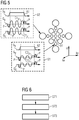
- Fig. 5 shows a schematic explanation of the gradient switching how to obtain the different spiral trajectories of a varying size.
- the gradient in the X direction A1, A2 is the read-out gradient which may be constant or variable in size.
- the phase encoding gradients C1Y, C1Z and C2Y and C2Z are applied.
- the gradients C1Y and C1Z have the same amplitude and the gradients C2Y and C2Z have the same higher amplitude.
- the additional phase encoding gradients P as shown for the gradient switching 60 and 62 shift the read-out at a certain position in k-space which is then the center of the read-out. As can be seen by varying the amplitudes with a smaller amplitude for the acquisition 61 the different radii can be obtained.
- Fig. 6 summarizes some of the steps for the generation of the MR image discussed above.
- a sequence of RF pulses is applied in order to generate a plurality of MR signal-echoes, wherein the signal acquisition schemas can include Cartesian or non-Cartesian sequences.
- the MR signal-echoes are detected in a non-homogenous undersampled 3 dimensional k-space in which the different spiral trajectories are used having different radii.
- the at least one MR image is reconstructed using this non-homogenous undersampled 3 dimensional k-space and using the compressed sensing technology.
- the way how the image reconstruction is known to the skilled person and comprises several data transformations and iterative optimization steps repeated several times.
- an image may be generated with a Fourier transform and a Sparsifying transform may be applied to this image.
- a Sparsifying transform may be applied to this image.
- an inverse Sparsifying and Fourier transform may be applied so that a (k-space) difference matrix can be created by subtracting the original from the denoised k-space data.
- the Fourier transform a difference image can be created.
- FIG 7 shows a schematic view of the reconstruction.
- Data set y 80 represents the acquired 3 dimensional MR data set as discussed above.
- data of a reference scan 79 is provided providing the coil sensitivities.
- the acquired data set is subject to a Wave Reconstruction Forward Model, WRFM, which is detailed in Figure 8 wherein a partial Fourier transform is carried out in the read direction in step S91.
- step S92 the echoes from the different coils are combined and in step S93 the result is modulated with the Point-Spread-Function in the phase encoding direction for the spiral i, with i being each unique spiral i.e. a specific amplitude or frequency combination.
- step S93 a modulation is carried out with a Point-Speed-F function in the slice direction and in step S94 the partial Fourier transform is carried out in the phase coding and slice encoding direction.
- data set 81 is obtained.
- an iterative reconstruction is carried out with an optimization process as discussed below.
- Data set 81 is then undergoing the sparsity transformation wherein W transforms the image space into the W-space.
- a solution then has to be found for the minimization that fulfills data consistency and transform sparsity.
- a sparse representation 82 of the image is provided after the transform. The goal of this transformation is to locally separate the wanted signal from the noise artefacts.
- the W-space is a better suited depiction of the image as the sparsity in the W-space is higher. This means that the image information is concentrated in a few pixels in the W-space while most of the other pixels only have a very low signal intensity. Different options exist for this W transform, one possible solution being a wavelet transformation.
- step S96 the result is demodulated with the Point-Spread -Function in the phase encoding direction and the corresponding spiral i.
- step S97 the demodulation is carried out with the Point-Spread-Function in the slice encoding direction and the corresponding spiral i and in step S98 the echoes are extracted from each coil so that in step S99 the partial inverse Fourier transform is carried out in the readout direction.
- the threshold is smaller than a difference or if a final number of iterations was made the final image 89 is obtained.
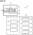
- Fig. 10 shows a schematic view of a MR system 9 configured to generate the MR images using spiral trajectories of different size.
- the MR system 9 comprises a magnet 10 generating a polarizing field B0.
- the object under examination 13 lying on a table 12 is moved into the center of the MR system 9 where MR signals can be detected after excitation using the receiving coils 11 wherein different coil sections or receiving coils may be used.
- the nuclear spins in the object, especially the part located in the receiving coil are excited and the currents induced by the relaxation is detected.
- the MR system furthermore comprises a control module 20 which is used for a central control of the MR system.
- the control module 20 comprises a gradient control unit 14 configured to control and switch the magnetic field gradients.
- an RF control unit 15 is provided configured to control and generate the RF pulses for the imaging sequences.
- An image sequence control unit 16 is provided which controls the sequence of the applied RF pulses and magnetic field gradients based on the selected imaging sequence and which thus controls the gradient control unit 14, the RF control unit 15 and the receiving coils 11.
- computer programs needed for operating the MR system and the imaging sequence is necessary for generating the MR images can be stored together with the generated MR images.
- the generated MR images may be displayed on a display 18 wherein an input unit 19 is provided used by a user for an interaction with the MR system 9.
- a control or processing unit 21 can coordinate the operation of the different functional units shown in Fig. 8 .
- the processing or control unit 20 can comprise one or more processors which can carry out instructions stored on a memory 17.
- the memory can include the program code to be executed by the processing unit 20 so as to implement the above-described functionality.
- the image sequence control unit 16 and the processing unit 21 can be especially configured to first of all acquire the k-space as discussed in connection with Fig. 3-5 wherein the compressed sensing technology for the reconstruction may be implemented by the processing unit 21, or in more general by the control module 20.
- the above-proposed method fulfills the requirement of a compressed sensing with a sparse sampling and a high incoherence of the undersampled artefacts so that a higher acceleration is obtained by combining the WAVE-CAIPIRINHA method with compressed sensing.
- the object under examination will no longer experience a constant pitch which may be experienced as more pleasant.
- the altering of the radius leads to a higher incoherence of the sampled data which is especially beneficial in iterative reconstruction technologies.
Landscapes
- Physics & Mathematics (AREA)
- High Energy & Nuclear Physics (AREA)
- Condensed Matter Physics & Semiconductors (AREA)
- General Physics & Mathematics (AREA)
- Engineering & Computer Science (AREA)
- Signal Processing (AREA)
- Health & Medical Sciences (AREA)
- General Health & Medical Sciences (AREA)
- Nuclear Medicine, Radiotherapy & Molecular Imaging (AREA)
- Radiology & Medical Imaging (AREA)
- Magnetic Resonance Imaging Apparatus (AREA)
Abstract
Description
- The present application relates to a method for generating at least one MR image, to an MR system configured to generate the at least one MR image, to a computer program and a carrier.
- To accelerate MR measurements, it is known to use undersampling schemes when acquiring the MR signals in k-space. Here, depending on the acceleration factor of the undersampling scheme, data samples are only taken for every second or third k-space position. Then a reconstruction of the undersampled MR data set can be implemented to obtain a reconstructed MR data set, the MR image.
- In this context, an image acquisition method called CAIPIRINHA is known. Furthermore, a method known as WAVE-CAIPI was introduced by Bilgic B. et al., as described in "WAVE-CAIPI for highly accelerated 3D imaging" Magnetic Resonance Imaging 73(6) 2015:2152-2162.
- If the acceleration factor is too high the reconstructed MRI data set can show artefacts and/or noise.
- WAVE-CAIPI applies identical oscillating readouts on one of the two axes perpendicular to the read-out direction which creates constant radii corkscrew trajectories through k-space for each acquired line. Accelerating scan times by increasing undersampling of WAVE-CAIPI acquisitions results in poor images with high g-factors. To avoid artefacts resulting in poor image quality, undersampling is normally limited to less than 3×3.
- Furthermore, the patient as object under examination hears an unpleasant high-pitched sound of approximately constant 100 dB in view of the occurring gradient switching.
- It is an object to avoid the above-mentioned drawbacks and to provide a method and a system allowing high undersampling factors with less artefacts while lowering the acoustic noise generated during the image acquisition.
- This need is met by the features of the independent claims. Further aspects are described in the dependent claims.
- According to a first aspect, a method for generating at least one MR image of an object under examination is provided in an MR system wherein the MR system comprises a plurality of signal receiving coils. According to the method, a sequence of radiofrequency, RF, pulses is applied in order to generate a plurality of MR signal echoes. These signal echoes are detected with a plurality of receiving coils in a 3 dimensional k-space, wherein the 3 dimensional k-space is undersampled with a plurality of spiral trajectories. The plurality of spiral trajectories have different radii resulting in a non-homogeneous undersampled 3 dimensional k-space. The at least one MR image is reconstructed using the non-homogeneous undersampled 3 dimensional k-space using a compressed sensing technology.
- With the use of the different radii for the spiral trajectories, the inhomogeneity of the acquired k-space is further increased. This feature in connection with the compressed sensing technology used for reconstructing MR images leads to a reduced acquisition time compared to conventional WAVE-CAIPI imaging methods. With the use of the compressed sensing technology the image artefacts can be further reduced. Furthermore, due to the different radii the frequency and the amplitude of the involved gradients generate a more pleasant sound than the WAVE-CAIPI methods known in the art.
- Preferably, the radii of the plurality of spiral trajectories increase with an increasing distance from a center of the non-homogeneous undersampled 3 dimensional k-space. The radius of a spiral close to the center of the k-space is smaller compared to regions further away from the center, so that the sampling density is higher close to the center. Accordingly, a higher image quality can be obtained.
- Preferably, the MR signal echoes of each of the spiral trajectories are detected in a first data sampling period which is the same for all of the plurality of spiral trajectories. This can mean that the data acquisition window has the same lengths for all the spiral trajectories.
- When the data sampling period is the same for all spiral trajectories it is possible that a sampling rate with which the MR signal echoes are sampled within the first sampling rate is larger for a first spiral of the plurality of spirals having a larger radius compared to the sampling rate with which the MR signal echoes are sampled within the first sampling period for a second spiral of the plurality of spirals having a smaller radius than the first spiral.
- In this example the sampling rate is increased in order to keep the number of spirals of the spiral trajectories fixed for the different sizes of the spiral parts.
- Furthermore, it is possible that the sampling rate with which the MR signal echoes are sampled within the first data sampling period is the same for all of the plurality of spirals. Here a number of spiral turns is smaller for a first spiral of the plurality of spirals having a larger radius compared to the number of turns for a second spiral of the plurality of spirals having a smaller radius than the first spiral.
- In this example, the sampling rate is kept constant, but the number of turns of the spiral decreases with increasing radius.
- The non-homogeneous undersampled 3 dimensional k-space is a k-space which is not fully sampled under the Nyquist theorem.
- Furthermore, the corresponding MR system is provided comprising an RF control unit configured to apply a sequence of RF pulses in order to generate a plurality of MR signal-echoes. The MR system furthermore comprises a gradient control unit configured to generate magnetic field gradients, and a plurality of signal receiving coils configured to detect the MR signal-echoes. An image sequence control unit is configured to control the application of RF pulses, magnetic field gradients and the detection of the MR signal-echoes in the 3 dimensional k-space such that the 3 dimensional k-space is undersampled with a plurality of spiral trajectories wherein the plurality of spiral trajectories have different radii resulting in a non-homogeneous undersampled 3 dimensional k-space. A processing unit is configured to reconstruct the at least one MR image using the non-homogeneous undersampled 3 dimensional k-space and using a compressed sensing technology.
- The MR system is configured to operate as discussed above or as discussed in further detail below.
- Additionally, a computer program comprising program code is provided which, when executed by an MR system, causes the MR system to perform a method as discussed above or as discussed in further detail below.
- Furthermore, a carrier comprising the program is provided wherein the carrier is one of an electronic signal, optical signal, radio signal, or computer readable storage medium.
- It should be understood that the features mentioned above and features yet to be explained below can be used not only in the respective combinations indicated, but also in other combinations or in isolation without departing from the scope of the present invention. Features of the above-mentioned aspects and embodiments described below may be combined with each other in other combinations unless explicitly mentioned otherwise.
- The foregoing and additional features and effects of the application will become apparent from the following detailed description, when read in conjunction with the accompanying drawings in which like reference numerals refer to like elements.
- Fig. 1
- shows a schematic view of an acquisition of a k-space with spiral trajectories as known in the art.
- Fig. 2
- is a schematic 2 dimensional top view of the acquisition as shown in
Fig. 1 as known in the art. - Fig. 3
- shows a schematic view of an acquisition of a 3 dimensional k-space with different radii according to the invention.
- Fig. 4
- shows a schematic 2 dimensional top view of the acquisition of
Fig. 3 . - Fig. 5
- shows a schematic view of a gradient switching used to generate the spiral trajectories having different radii.
- Fig. 6
- shows a example flowchart of a method carried out to generate an MR image using spiral trajectories of different radii and a compressed sensing technology.
- Fig. 7
- shows a schematic flowchart of a method used to reconstruct the image based on a non-homogenously undersampled 3 dimensional k-space with spirals of different radii.
- Fig. 8
- shows a schematic more detailed flowchart for some of the steps carried out in the method of
Fig. 7 . - Fig. 9
- shows a schematic more detailed flowchart for some of the steps carried out in the method of
Fig. 7 . - Fig. 10
- shows an example schematic view of an MR system configured to acquire and generate a MR image as discussed in connection with
Fig. 3-9 . - In the following, embodiments of the invention will be described in detail with reference to the accompanying drawings. It is to be understood that the following description of embodiments is not to be taken in a limiting sense. The scope of the invention is not intended to be limited by the embodiments described hereinafter or by the drawings, which are to be illustrative only.
- The drawings are to be regarded as being schematic representations, and elements illustrated in the drawings are not necessarily shown to scale. Rather the various elements are represented such that their function and general purpose becomes apparent to a person skilled in the art. Any connection or coupling between functional blocks, devices, components of physical or functional units shown in the drawings and described hereinafter may be implemented by an indirect connection or coupling. A coupling between components may be established over a wired or wireless connection. Functional blocks may be implemented in hardware, software, firmware, or a combination thereof.
-
Fig. 1 shows a schematic view of an acquisition scheme of a k-space in which the k-space is a 3 dimensional k-space which is sampled by different spiral trajectories. The k-space 30 is sampled by a plurality ofspiral trajectories 31, wherein each spiral trajectory has acentral axis 32. Thecentral axes 32 are parallel to one another and the same radius is used for each of the spiral trajectories. The image acquisition is in the Kx direction, the phase encoding directions are Ky, Kz. -
Fig. 2 is a schematic 2 dimensional top view of the acquisition scheme ofFig. 1 with thedifferent spiral trajectories 31. As can be seen fromFig. 2 all spiral trajectories have the same radius r1. -
Fig. 3 now shows an embodiment where the 3 dimensional k-space 40 is undersampled usingtrajectories 50 having different radii. A center of the k-space 41 is located in the middle of the space defined by the axes Kz and Ky and is located in the middle of the extension of the k-space in the Kx direction. Thedifferent spirals 50 are now designed such that spiral trajectories such astrajectories 51 have a smaller radius compared totrajectories Fig. 4 the trajectories around the center of k-space 41 have the smallest radius r1 wherein spirals 52 located further away have a larger radius r2 and spirals 53 have a radius r3. Thesespirals 54 having the greatest distance to thecenter 41 have the largest radius r4. It should be understood that a different distribution of the different radii is possible, but preferably the sampling density is higher in the space close to the k-space center meaning a smaller radius. The image acquisition is such that the different spirals are acquired consecutively. The gradients in the Kz and Ky directions are switched to a first point of the spiral and then the spiral trajectory is followed by switching on the read-out gradient in the Kx direction and by switching the gradients in the Ky, Kz direction in order to have a circular pattern in this plane. Thecentral axis 55 of the different spirals are preferably parallel to one another. - It is possible to use the same duration of the data sampling period for all of the spirals. As the path of one spiral having a larger radius is longer compared to a spiral having a smaller radius two possible options exist. The first option is to increase the data sampling rate for the trajectories having a larger radius in order to keep the number of turns of the spiral fixed. The other option is to keep the sampling rate constant so that a smaller number of spiral turns are present in the spiral having a larger diameter compared to a spiral having a small diameter.
-
Fig. 5 shows a schematic explanation of the gradient switching how to obtain the different spiral trajectories of a varying size. For thespiral trajectory 51 the gradient switching 61 is shown, for thetrajectory 52 the switching 62. The gradient in the X direction A1, A2 is the read-out gradient which may be constant or variable in size. In addition to the read-out gradient the phase encoding gradients C1Y, C1Z and C2Y and C2Z are applied. The gradients C1Y and C1Z have the same amplitude and the gradients C2Y and C2Z have the same higher amplitude. With this sinusoidal shape of the gradients in the Gy and Gz direction a k-space sampling is obtained which is indicated here as a circle. The additional phase encoding gradients P as shown for the gradient switching 60 and 62 shift the read-out at a certain position in k-space which is then the center of the read-out. As can be seen by varying the amplitudes with a smaller amplitude for theacquisition 61 the different radii can be obtained. -
Fig. 6 summarizes some of the steps for the generation of the MR image discussed above. In step S71 a sequence of RF pulses is applied in order to generate a plurality of MR signal-echoes, wherein the signal acquisition schemas can include Cartesian or non-Cartesian sequences. In step S72 the MR signal-echoes are detected in a non-homogenous undersampled 3 dimensional k-space in which the different spiral trajectories are used having different radii. In step S73 the at least one MR image is reconstructed using this non-homogenous undersampled 3 dimensional k-space and using the compressed sensing technology. The way how the image reconstruction is known to the skilled person and comprises several data transformations and iterative optimization steps repeated several times. After the collection of the k-space data as discussed above an image may be generated with a Fourier transform and a Sparsifying transform may be applied to this image. After removing an aliasing artefacts an inverse Sparsifying and Fourier transform may be applied so that a (k-space) difference matrix can be created by subtracting the original from the denoised k-space data. With the Fourier transform a difference image can be created. By comparing the initial and the updated images it can be determined whether the optimization algorithm is repeated with the application of the Sparsifying transform such as a wavelet decomposition. -
Figure 7 shows a schematic view of the reconstruction.Data set y 80 represents the acquired 3 dimensional MR data set as discussed above. In addition data of areference scan 79 is provided providing the coil sensitivities. The acquired data set is subject to a Wave Reconstruction Forward Model, WRFM, which is detailed inFigure 8 wherein a partial Fourier transform is carried out in the read direction in step S91. In step S92 the echoes from the different coils are combined and in step S93 the result is modulated with the Point-Spread-Function in the phase encoding direction for the spiral i, with i being each unique spiral i.e. a specific amplitude or frequency combination. In step S93 a modulation is carried out with a Point-Speed-F function in the slice direction and in step S94 the partial Fourier transform is carried out in the phase coding and slice encoding direction. After the steps S91 to S94 data set 81 is obtained. Then an iterative reconstruction is carried out with an optimization process as discussed below. Data set 81 is then undergoing the sparsity transformation wherein W transforms the image space into the W-space. In the optimization procedure a solution then has to be found for the minimization that fulfills data consistency and transform sparsity. Accordingly asparse representation 82 of the image is provided after the transform. The goal of this transformation is to locally separate the wanted signal from the noise artefacts. The W-space is a better suited depiction of the image as the sparsity in the W-space is higher. This means that the image information is concentrated in a few pixels in the W-space while most of the other pixels only have a very low signal intensity. Different options exist for this W transform, one possible solution being a wavelet transformation. - After the W transformation that wanted signal is now to a high degree separated from the noisy parts. This allows the removal of the noise by a thresholding procedure in which all the pixels having a value smaller than a threshold are set to zero and in which the threshold is subtracted from all the other pixel values so that a
data set 83 is generated. This is also called soft thresholding. As many pixels in the W-space now have the value of zero, the number of non-zero pixels is lower. 83 then undergoes the inverse W transform so thatimage 84 is obtained. To thisimage 84 the Wave Reconstruction Reverse Model, WRRM, is applied which is explained in further detail inFigure 9 . InFigure 9 a partial inverse Fourier transform is carried out in the phase and slice encoding direction step S95. In step S96 the result is demodulated with the Point-Spread -Function in the phase encoding direction and the corresponding spiral i. In step S97 the demodulation is carried out with the Point-Spread-Function in the slice encoding direction and the corresponding spiral i and in step S98 the echoes are extracted from each coil so that in step S99 the partial inverse Fourier transform is carried out in the readout direction. - The result is
image 85. Then a masking is carried out so that the k-space data set 85 is fitted such that only the points of k-space that were also measured in the data set 80 remain. The rest of the k-space is set to zero. After the masking with the measured trajectory the trajectory k-space A·x is obtained in thedata set 86. x is the estimated image and A is the transformation. In the following the difference in k-space is created by subtracting the k-space Ax from the measured k-space y so that a difference Ax-y is obtained which corresponds to the error, the non-consistency that this threshold used above has created. This difference is a correction k-space data set 87. To reconstruct data set 87 again the wave reconstruction forward model is applied as discussed above inFigure 8 . Accordingly adifference image 88 is obtained and this updated image now has less noise-like artefacts than the image before the update. This process can now be repeated until either a least square difference of the data consistency term is smaller than a threshold or a predefined number of iterations has been reached. - If the threshold is smaller than a difference or if a final number of iterations was made the
final image 89 is obtained. -
Fig. 10 shows a schematic view of aMR system 9 configured to generate the MR images using spiral trajectories of different size. TheMR system 9 comprises amagnet 10 generating a polarizing field B0. The object underexamination 13 lying on a table 12 is moved into the center of theMR system 9 where MR signals can be detected after excitation using the receiving coils 11 wherein different coil sections or receiving coils may be used. By applying RF pulses and the magnetic field gradients, the nuclear spins in the object, especially the part located in the receiving coil are excited and the currents induced by the relaxation is detected. The way how MR images are generated and how the MR signals are detected using a sequence of RF pulses and the sequence of magnetic field gradients are known in the art so that a detailed explanation thereof can be omitted. Furthermore, details for the switching of magnetic field gradients were given above. - The MR system furthermore comprises a
control module 20 which is used for a central control of the MR system. Thecontrol module 20 comprises agradient control unit 14 configured to control and switch the magnetic field gradients. Furthermore, anRF control unit 15 is provided configured to control and generate the RF pulses for the imaging sequences. An imagesequence control unit 16 is provided which controls the sequence of the applied RF pulses and magnetic field gradients based on the selected imaging sequence and which thus controls thegradient control unit 14, theRF control unit 15 and the receiving coils 11. In amemory 17, computer programs needed for operating the MR system and the imaging sequence is necessary for generating the MR images can be stored together with the generated MR images. The generated MR images may be displayed on adisplay 18 wherein aninput unit 19 is provided used by a user for an interaction with theMR system 9. A control orprocessing unit 21 can coordinate the operation of the different functional units shown inFig. 8 . The processing orcontrol unit 20 can comprise one or more processors which can carry out instructions stored on amemory 17. The memory can include the program code to be executed by theprocessing unit 20 so as to implement the above-described functionality. Especially the imagesequence control unit 16 and theprocessing unit 21 can be especially configured to first of all acquire the k-space as discussed in connection withFig. 3-5 wherein the compressed sensing technology for the reconstruction may be implemented by theprocessing unit 21, or in more general by thecontrol module 20. - With the above-described method is it is possible to reduce the scan time as less trajectories are needed for the position of the k-space compared to the situation discussed above in connection with
Fig. 1 and 2 where a constant radius was used. Accordingly, a higher acceleration is obtained. Furthermore, the above-proposed method fulfills the requirement of a compressed sensing with a sparse sampling and a high incoherence of the undersampled artefacts so that a higher acceleration is obtained by combining the WAVE-CAIPIRINHA method with compressed sensing. - Furthermore, by altering the frequency and the amplitude of the spiral trajectories the object under examination will no longer experience a constant pitch which may be experienced as more pleasant. In total, the altering of the radius leads to a higher incoherence of the sampled data which is especially beneficial in iterative reconstruction technologies.
Claims (13)
- A method for generating at least one MR image of an object in an MR system comprising a plurality of signal receiving coils, the method comprising at the MR system:- applying a sequence of RF pulses in order to generate a plurality of MR signal-echoes,- detecting the MR signal-echoes with the plurality of signal receiving coils in a 3 dimensional k-space, wherein the 3 dimensional k-space is undersampled with a plurality of spiral trajectories, the plurality of spiral trajectories having different radii resulting in a non-homogeneous undersampled 3 dimensional k-space,- reconstructing the at least one MR image using the non-homogeneous under sampled 3 dimensional k-space based on a compressed sensing technology.
- The method according to claim 1, wherein the radii of the plurality of spiral trajectories increase with an increasing distance from a center of the non-homogeneous undersampled 3 dimensional k-space.
- The method according to claim 1 or 2, wherein the MR signal-echoes of each of the plurality of spiral trajectories are detected in a first data sampling period which is the same for all of the plurality of spiral trajectories.
- The method according to claim 3, wherein a sampling rate with which the MR signal-echoes are sampled within the first data sampling period is larger for a first spiral of the plurality of spirals having a larger radius compared to the sampling rate which with the MR signal-echoes are sampled within the first sampling period for a second spiral of the plurality of spirals having a smaller radius than the first spiral.
- The method according to claim 3, wherein a sampling rate with which the MR signal-echoes are sampled within the first data sampling period is the same for all of the plurality of spirals, wherein a number of spiral turns is smaller for a first spiral of the plurality of spirals having a larger radius compared to the number of turns for a second spiral of the plurality of spirals having a smaller radius than the first spiral.
- The method according to any of the preceding claims, wherein the non-homogenous undersampled 3 dimensional k-space is a k-space which is not fully sampled under the Nyquist theorem.
- An MR system configured to generate at least one MR image of an object under examination, the MR system comprising:- an RF control unit configured to apply a sequence of RF pulses in order to generate a plurality of MR signal- echoes,- a gradient control unit configured to generate magnetic field gradients,- a plurality of signal receiving coils configured to detect MR signal echoes- an image sequence control unit configured to control an application of RF pulses, magnetic field gradients and the detection of MR signal echoes in 3 dimensional k-space such that the 3 dimensional k-space is undersampled with a plurality of spiral trajectories, the plurality of spiral trajectories having different radii resulting in a non-homogeneous undersampled 3 dimensional k-space,- a processing unit configured to reconstruct the at least one MR image using the non-homogeneous undersampled 3 dimensional k-space based on a compressed sensing technology.
- The MR system according to claim 7, wherein the image sequence control unit is configured to sample the non-homogeneous undersampled 3 dimensional k-space such that the radii of the plurality of spiral trajectories increase with an increasing distance from a center of the non-homogeneous undersampled 3 dimensional k-space.
- The MR system according to claim 7 or 8, wherein the image sequence control unit is configured to detect the MR signal-echoes of each of the plurality of spiral trajectories in a first data sampling period which is the same for all of the plurality of spiral trajectories.
- The MR system according to claim 9, wherein the image sequence control unit is configured to use a sampling rate with which the MR signal-echoes are sampled within the first data sampling period that is larger for a first one of the plurality of spirals having a larger radius compared to the sampling rate with which the MR signal-echoes are sampled within the first sampling period for a second one of the plurality of spirals having a smaller radius than the first one of the plurality of spirals.
- The MR system according to claim 9, wherein the image sequence control unit is configured to use a sampling rate with which the MR signal-echoes are sampled within the first data sampling period that is the same for all of the plurality of spirals, wherein a number of spiral turns is smaller for a first spiral of the plurality of spirals having a larger radius compared to the number of turns for a second spiral of the plurality of spirals having a smaller radius than the first spiral.
- A computer program comprising program code that, when executed by a control unit of an MR system cause the MR system to perform a method as mentioned in any of claims 1 to 6.
- A carrier comprising the computer program of claim 12, wherein the carrier is one of an electronic signal, optical signal, radio signal, or computer readable storage medium.
Priority Applications (2)
| Application Number | Priority Date | Filing Date | Title |
|---|---|---|---|
| EP20152184.6A EP3851865B1 (en) | 2020-01-16 | 2020-01-16 | Accelerated wave data mr acquisition |
| US17/149,073 US11397234B2 (en) | 2020-01-16 | 2021-01-14 | Method and system for accelerated wave data magnetic resonance acquisition |
Applications Claiming Priority (1)
| Application Number | Priority Date | Filing Date | Title |
|---|---|---|---|
| EP20152184.6A EP3851865B1 (en) | 2020-01-16 | 2020-01-16 | Accelerated wave data mr acquisition |
Publications (3)
| Publication Number | Publication Date |
|---|---|
| EP3851865A1 true EP3851865A1 (en) | 2021-07-21 |
| EP3851865C0 EP3851865C0 (en) | 2023-11-22 |
| EP3851865B1 EP3851865B1 (en) | 2023-11-22 |
Family
ID=69174382
Family Applications (1)
| Application Number | Title | Priority Date | Filing Date |
|---|---|---|---|
| EP20152184.6A Active EP3851865B1 (en) | 2020-01-16 | 2020-01-16 | Accelerated wave data mr acquisition |
Country Status (2)
| Country | Link |
|---|---|
| US (1) | US11397234B2 (en) |
| EP (1) | EP3851865B1 (en) |
Citations (1)
| Publication number | Priority date | Publication date | Assignee | Title |
|---|---|---|---|---|
| US9953439B2 (en) * | 2014-11-25 | 2018-04-24 | University Of Virginia Patent Foundation | Systems and methods for three-dimensional spiral perfusion imaging |
Family Cites Families (3)
| Publication number | Priority date | Publication date | Assignee | Title |
|---|---|---|---|---|
| US7245124B2 (en) * | 2005-04-12 | 2007-07-17 | Mayo Foundation For Medical Education And Research | Under-sampled 3D MRI using a shells k-space sampling trajectory |
| CN109310361B (en) * | 2016-04-07 | 2022-04-26 | 上海联影医疗科技股份有限公司 | System and method for fast magnetic resonance imaging |
| EP3382413B1 (en) * | 2017-03-27 | 2022-08-10 | Siemens Healthcare GmbH | 2d navigator technique in mri |
-
2020
- 2020-01-16 EP EP20152184.6A patent/EP3851865B1/en active Active
-
2021
- 2021-01-14 US US17/149,073 patent/US11397234B2/en active Active
Patent Citations (1)
| Publication number | Priority date | Publication date | Assignee | Title |
|---|---|---|---|---|
| US9953439B2 (en) * | 2014-11-25 | 2018-04-24 | University Of Virginia Patent Foundation | Systems and methods for three-dimensional spiral perfusion imaging |
Non-Patent Citations (2)
| Title |
|---|
| BERKIN BILGIC ET AL: "Wave-CAIPI for highly accelerated 3D imaging : Wave-CAIPI for Highly Accelerated 3D Imaging", MAGNETIC RESONANCE IN MEDICINE., vol. 73, no. 6, 1 July 2014 (2014-07-01), US, pages 2152 - 2162, XP055645454, ISSN: 0740-3194, DOI: 10.1002/mrm.25347 * |
| BILGIC B. ET AL.: "WAVE-CAIPI for highly accelerated 3D imaging", MAGNETIC RESONANCE IMAGING, vol. 73, no. 6, 2015, pages 2152 - 2162, XP055645454, DOI: 10.1002/mrm.25347 |
Also Published As
| Publication number | Publication date |
|---|---|
| EP3851865C0 (en) | 2023-11-22 |
| EP3851865B1 (en) | 2023-11-22 |
| US11397234B2 (en) | 2022-07-26 |
| US20210223344A1 (en) | 2021-07-22 |
Similar Documents
| Publication | Publication Date | Title |
|---|---|---|
| US9964615B2 (en) | MR image reconstruction using compressed sensing | |
| CN104395772B (en) | Magnetic resonance image reconstruction method with respiratory mot detection during sampling of central and peripheral k- space areas | |
| EP3149508B1 (en) | Mr imaging using multi-echo k-space acquisition | |
| US10670678B2 (en) | MR imaging using stack-of stars acquisition | |
| US10191133B2 (en) | MR imaging using multi-echo segmented k-space acquisition | |
| JP6513398B2 (en) | MR image reconstruction using prior information constrained regularization | |
| US9482732B2 (en) | MRI reconstruction with motion-dependent regularization | |
| CN109310361B (en) | System and method for fast magnetic resonance imaging | |
| US10950014B2 (en) | Method and apparatus for adaptive compressed sensing (CS) to correct motion artifacts in magnetic resonance imaging (MRI) | |
| CN106574954B (en) | Parallel MR imaging with Nyquist artifact correction for EPI | |
| US10203394B2 (en) | Metal resistant MR imaging | |
| CN102947721A (en) | Method of reconstructing a magnetic resonance image of an object considering higher-order dynamic fields | |
| KR101283532B1 (en) | Magnet resonance imaging device and method for constructing mr image using the same | |
| EP3855200A1 (en) | Artifact and/or noise reduction for magnetic resonance fingerprinting data based on a neural network | |
| US11313934B2 (en) | Method for 2D magnetic resonance imaging, corresponding MRI device, computer program, and computer-readable storage medium | |
| US10845442B2 (en) | Magnetic resonance imaging apparatus, processing apparatus and medical image processing method | |
| EP3851865B1 (en) | Accelerated wave data mr acquisition | |
| US10151811B2 (en) | Method for producing an MR image and correspondingly designed magnetic resonance scanner | |
| US11914017B2 (en) | Magnetic resonance imaging apparatus and image processing method | |
| US9476954B2 (en) | Method and apparatus to generate magnetic resonance data | |
| EP3770625B1 (en) | Mri using compressed sensing with improved regularization parameter | |
| US20260118461A1 (en) | Method for Multispectral Magnetic Resonance Imaging | |
| CN119916278A (en) | System and method for reduced fine line artifacts in magnetic resonance imaging | |
| CN113835058A (en) | Method for acquiring and processing MR data, MRI system and method, storage medium |
Legal Events
| Date | Code | Title | Description |
|---|---|---|---|
| PUAI | Public reference made under article 153(3) epc to a published international application that has entered the european phase |
Free format text: ORIGINAL CODE: 0009012 |
|
| STAA | Information on the status of an ep patent application or granted ep patent |
Free format text: STATUS: THE APPLICATION HAS BEEN PUBLISHED |
|
| AK | Designated contracting states |
Kind code of ref document: A1 Designated state(s): AL AT BE BG CH CY CZ DE DK EE ES FI FR GB GR HR HU IE IS IT LI LT LU LV MC MK MT NL NO PL PT RO RS SE SI SK SM TR |
|
| STAA | Information on the status of an ep patent application or granted ep patent |
Free format text: STATUS: REQUEST FOR EXAMINATION WAS MADE |
|
| 17P | Request for examination filed |
Effective date: 20220121 |
|
| RBV | Designated contracting states (corrected) |
Designated state(s): AL AT BE BG CH CY CZ DE DK EE ES FI FR GB GR HR HU IE IS IT LI LT LU LV MC MK MT NL NO PL PT RO RS SE SI SK SM TR |
|
| GRAP | Despatch of communication of intention to grant a patent |
Free format text: ORIGINAL CODE: EPIDOSNIGR1 |
|
| STAA | Information on the status of an ep patent application or granted ep patent |
Free format text: STATUS: GRANT OF PATENT IS INTENDED |
|
| INTG | Intention to grant announced |
Effective date: 20230728 |
|
| GRAS | Grant fee paid |
Free format text: ORIGINAL CODE: EPIDOSNIGR3 |
|
| GRAA | (expected) grant |
Free format text: ORIGINAL CODE: 0009210 |
|
| STAA | Information on the status of an ep patent application or granted ep patent |
Free format text: STATUS: THE PATENT HAS BEEN GRANTED |
|
| AK | Designated contracting states |
Kind code of ref document: B1 Designated state(s): AL AT BE BG CH CY CZ DE DK EE ES FI FR GB GR HR HU IE IS IT LI LT LU LV MC MK MT NL NO PL PT RO RS SE SI SK SM TR |
|
| REG | Reference to a national code |
Ref country code: GB Ref legal event code: FG4D |
|
| REG | Reference to a national code |
Ref country code: CH Ref legal event code: EP Ref country code: DE Ref legal event code: R096 Ref document number: 602020021312 Country of ref document: DE |
|
| REG | Reference to a national code |
Ref country code: IE Ref legal event code: FG4D |
|
| U01 | Request for unitary effect filed |
Effective date: 20231128 |
|
| U07 | Unitary effect registered |
Designated state(s): AT BE BG DE DK EE FI FR IT LT LU LV MT NL PT SE SI Effective date: 20231204 |
|
| RAP2 | Party data changed (patent owner data changed or rights of a patent transferred) |
Owner name: SIEMENS HEALTHINEERS AG |
|
| U1K | Transfer of rights of the unitary patent after the registration of the unitary effect |
Owner name: SIEMENS HEALTHINEERS AG; DE |
|
| U20 | Renewal fee for the european patent with unitary effect paid |
Year of fee payment: 5 Effective date: 20240119 |
|
| PG25 | Lapsed in a contracting state [announced via postgrant information from national office to epo] |
Ref country code: GR Free format text: LAPSE BECAUSE OF FAILURE TO SUBMIT A TRANSLATION OF THE DESCRIPTION OR TO PAY THE FEE WITHIN THE PRESCRIBED TIME-LIMIT Effective date: 20240223 |
|
| PG25 | Lapsed in a contracting state [announced via postgrant information from national office to epo] |
Ref country code: IS Free format text: LAPSE BECAUSE OF FAILURE TO SUBMIT A TRANSLATION OF THE DESCRIPTION OR TO PAY THE FEE WITHIN THE PRESCRIBED TIME-LIMIT Effective date: 20240322 |
|
| PG25 | Lapsed in a contracting state [announced via postgrant information from national office to epo] |
Ref country code: ES Free format text: LAPSE BECAUSE OF FAILURE TO SUBMIT A TRANSLATION OF THE DESCRIPTION OR TO PAY THE FEE WITHIN THE PRESCRIBED TIME-LIMIT Effective date: 20231122 |
|
| PG25 | Lapsed in a contracting state [announced via postgrant information from national office to epo] |
Ref country code: IS Free format text: LAPSE BECAUSE OF FAILURE TO SUBMIT A TRANSLATION OF THE DESCRIPTION OR TO PAY THE FEE WITHIN THE PRESCRIBED TIME-LIMIT Effective date: 20240322 Ref country code: GR Free format text: LAPSE BECAUSE OF FAILURE TO SUBMIT A TRANSLATION OF THE DESCRIPTION OR TO PAY THE FEE WITHIN THE PRESCRIBED TIME-LIMIT Effective date: 20240223 Ref country code: ES Free format text: LAPSE BECAUSE OF FAILURE TO SUBMIT A TRANSLATION OF THE DESCRIPTION OR TO PAY THE FEE WITHIN THE PRESCRIBED TIME-LIMIT Effective date: 20231122 |
|
| PG25 | Lapsed in a contracting state [announced via postgrant information from national office to epo] |
Ref country code: RS Free format text: LAPSE BECAUSE OF FAILURE TO SUBMIT A TRANSLATION OF THE DESCRIPTION OR TO PAY THE FEE WITHIN THE PRESCRIBED TIME-LIMIT Effective date: 20231122 Ref country code: PL Free format text: LAPSE BECAUSE OF FAILURE TO SUBMIT A TRANSLATION OF THE DESCRIPTION OR TO PAY THE FEE WITHIN THE PRESCRIBED TIME-LIMIT Effective date: 20231122 Ref country code: NO Free format text: LAPSE BECAUSE OF FAILURE TO SUBMIT A TRANSLATION OF THE DESCRIPTION OR TO PAY THE FEE WITHIN THE PRESCRIBED TIME-LIMIT Effective date: 20240222 Ref country code: HR Free format text: LAPSE BECAUSE OF FAILURE TO SUBMIT A TRANSLATION OF THE DESCRIPTION OR TO PAY THE FEE WITHIN THE PRESCRIBED TIME-LIMIT Effective date: 20231122 |
|
| U1N | Appointed representative for the unitary patent procedure changed after the registration of the unitary effect |
Representative=s name: SIEMENS HEALTHINEERS PATENT ATTORNEYS; DE |
|
| PG25 | Lapsed in a contracting state [announced via postgrant information from national office to epo] |
Ref country code: CZ Free format text: LAPSE BECAUSE OF FAILURE TO SUBMIT A TRANSLATION OF THE DESCRIPTION OR TO PAY THE FEE WITHIN THE PRESCRIBED TIME-LIMIT Effective date: 20231122 |
|
| PG25 | Lapsed in a contracting state [announced via postgrant information from national office to epo] |
Ref country code: SK Free format text: LAPSE BECAUSE OF FAILURE TO SUBMIT A TRANSLATION OF THE DESCRIPTION OR TO PAY THE FEE WITHIN THE PRESCRIBED TIME-LIMIT Effective date: 20231122 |
|
| PG25 | Lapsed in a contracting state [announced via postgrant information from national office to epo] |
Ref country code: SM Free format text: LAPSE BECAUSE OF FAILURE TO SUBMIT A TRANSLATION OF THE DESCRIPTION OR TO PAY THE FEE WITHIN THE PRESCRIBED TIME-LIMIT Effective date: 20231122 Ref country code: SK Free format text: LAPSE BECAUSE OF FAILURE TO SUBMIT A TRANSLATION OF THE DESCRIPTION OR TO PAY THE FEE WITHIN THE PRESCRIBED TIME-LIMIT Effective date: 20231122 Ref country code: RO Free format text: LAPSE BECAUSE OF FAILURE TO SUBMIT A TRANSLATION OF THE DESCRIPTION OR TO PAY THE FEE WITHIN THE PRESCRIBED TIME-LIMIT Effective date: 20231122 Ref country code: CZ Free format text: LAPSE BECAUSE OF FAILURE TO SUBMIT A TRANSLATION OF THE DESCRIPTION OR TO PAY THE FEE WITHIN THE PRESCRIBED TIME-LIMIT Effective date: 20231122 |
|
| REG | Reference to a national code |
Ref country code: DE Ref legal event code: R097 Ref document number: 602020021312 Country of ref document: DE |
|
| PG25 | Lapsed in a contracting state [announced via postgrant information from national office to epo] |
Ref country code: MC Free format text: LAPSE BECAUSE OF FAILURE TO SUBMIT A TRANSLATION OF THE DESCRIPTION OR TO PAY THE FEE WITHIN THE PRESCRIBED TIME-LIMIT Effective date: 20231122 |
|
| PG25 | Lapsed in a contracting state [announced via postgrant information from national office to epo] |
Ref country code: MC Free format text: LAPSE BECAUSE OF FAILURE TO SUBMIT A TRANSLATION OF THE DESCRIPTION OR TO PAY THE FEE WITHIN THE PRESCRIBED TIME-LIMIT Effective date: 20231122 |
|
| REG | Reference to a national code |
Ref country code: CH Ref legal event code: PL |
|
| PLBE | No opposition filed within time limit |
Free format text: ORIGINAL CODE: 0009261 |
|
| STAA | Information on the status of an ep patent application or granted ep patent |
Free format text: STATUS: NO OPPOSITION FILED WITHIN TIME LIMIT |
|
| PG25 | Lapsed in a contracting state [announced via postgrant information from national office to epo] |
Ref country code: CH Free format text: LAPSE BECAUSE OF NON-PAYMENT OF DUE FEES Effective date: 20240131 |
|
| 26N | No opposition filed |
Effective date: 20240823 |
|
| PG25 | Lapsed in a contracting state [announced via postgrant information from national office to epo] |
Ref country code: CH Free format text: LAPSE BECAUSE OF NON-PAYMENT OF DUE FEES Effective date: 20240131 |
|
| PG25 | Lapsed in a contracting state [announced via postgrant information from national office to epo] |
Ref country code: IE Free format text: LAPSE BECAUSE OF NON-PAYMENT OF DUE FEES Effective date: 20240116 |
|
| PG25 | Lapsed in a contracting state [announced via postgrant information from national office to epo] |
Ref country code: IE Free format text: LAPSE BECAUSE OF NON-PAYMENT OF DUE FEES Effective date: 20240116 |
|
| U20 | Renewal fee for the european patent with unitary effect paid |
Year of fee payment: 6 Effective date: 20250120 |
|
| PG25 | Lapsed in a contracting state [announced via postgrant information from national office to epo] |
Ref country code: CY Free format text: LAPSE BECAUSE OF FAILURE TO SUBMIT A TRANSLATION OF THE DESCRIPTION OR TO PAY THE FEE WITHIN THE PRESCRIBED TIME-LIMIT; INVALID AB INITIO Effective date: 20200116 |
|
| PG25 | Lapsed in a contracting state [announced via postgrant information from national office to epo] |
Ref country code: HU Free format text: LAPSE BECAUSE OF FAILURE TO SUBMIT A TRANSLATION OF THE DESCRIPTION OR TO PAY THE FEE WITHIN THE PRESCRIBED TIME-LIMIT; INVALID AB INITIO Effective date: 20200116 |
|
| PG25 | Lapsed in a contracting state [announced via postgrant information from national office to epo] |
Ref country code: TR Free format text: LAPSE BECAUSE OF FAILURE TO SUBMIT A TRANSLATION OF THE DESCRIPTION OR TO PAY THE FEE WITHIN THE PRESCRIBED TIME-LIMIT Effective date: 20231122 |
|
| U20 | Renewal fee for the european patent with unitary effect paid |
Year of fee payment: 7 Effective date: 20260119 |
|
| PGFP | Annual fee paid to national office [announced via postgrant information from national office to epo] |
Ref country code: GB Payment date: 20260210 Year of fee payment: 7 |