EP3851826A1 - Optics device for testing cameras useful on vehicles - Google Patents
Optics device for testing cameras useful on vehicles Download PDFInfo
- Publication number
- EP3851826A1 EP3851826A1 EP21151761.0A EP21151761A EP3851826A1 EP 3851826 A1 EP3851826 A1 EP 3851826A1 EP 21151761 A EP21151761 A EP 21151761A EP 3851826 A1 EP3851826 A1 EP 3851826A1
- Authority
- EP
- European Patent Office
- Prior art keywords
- camera
- optic components
- optic
- target
- testing device
- Prior art date
- Legal status (The legal status is an assumption and is not a legal conclusion. Google has not performed a legal analysis and makes no representation as to the accuracy of the status listed.)
- Granted
Links
Images


Classifications
-
- G—PHYSICS
- G01—MEASURING; TESTING
- G01M—TESTING STATIC OR DYNAMIC BALANCE OF MACHINES OR STRUCTURES; TESTING OF STRUCTURES OR APPARATUS, NOT OTHERWISE PROVIDED FOR
- G01M99/00—Subject matter not provided for in other groups of this subclass
- G01M99/002—Thermal testing
-
- H—ELECTRICITY
- H04—ELECTRIC COMMUNICATION TECHNIQUE
- H04N—PICTORIAL COMMUNICATION, e.g. TELEVISION
- H04N17/00—Diagnosis, testing or measuring for television systems or their details
- H04N17/002—Diagnosis, testing or measuring for television systems or their details for television cameras
-
- G—PHYSICS
- G01—MEASURING; TESTING
- G01M—TESTING STATIC OR DYNAMIC BALANCE OF MACHINES OR STRUCTURES; TESTING OF STRUCTURES OR APPARATUS, NOT OTHERWISE PROVIDED FOR
- G01M11/00—Testing of optical apparatus; Testing structures by optical methods not otherwise provided for
- G01M11/02—Testing optical properties
- G01M11/0207—Details of measuring devices
-
- G—PHYSICS
- G01—MEASURING; TESTING
- G01M—TESTING STATIC OR DYNAMIC BALANCE OF MACHINES OR STRUCTURES; TESTING OF STRUCTURES OR APPARATUS, NOT OTHERWISE PROVIDED FOR
- G01M11/00—Testing of optical apparatus; Testing structures by optical methods not otherwise provided for
- G01M11/02—Testing optical properties
- G01M11/0242—Testing optical properties by measuring geometrical properties or aberrations
- G01M11/0257—Testing optical properties by measuring geometrical properties or aberrations by analyzing the image formed by the object to be tested
- G01M11/0264—Testing optical properties by measuring geometrical properties or aberrations by analyzing the image formed by the object to be tested by using targets or reference patterns
-
- H—ELECTRICITY
- H04—ELECTRIC COMMUNICATION TECHNIQUE
- H04N—PICTORIAL COMMUNICATION, e.g. TELEVISION
- H04N23/00—Cameras or camera modules comprising electronic image sensors; Control thereof
- H04N23/50—Constructional details
- H04N23/54—Mounting of pick-up tubes, electronic image sensors, deviation or focusing coils
-
- H—ELECTRICITY
- H04—ELECTRIC COMMUNICATION TECHNIQUE
- H04N—PICTORIAL COMMUNICATION, e.g. TELEVISION
- H04N23/00—Cameras or camera modules comprising electronic image sensors; Control thereof
- H04N23/56—Cameras or camera modules comprising electronic image sensors; Control thereof provided with illuminating means
-
- H—ELECTRICITY
- H04—ELECTRIC COMMUNICATION TECHNIQUE
- H04N—PICTORIAL COMMUNICATION, e.g. TELEVISION
- H04N23/00—Cameras or camera modules comprising electronic image sensors; Control thereof
- H04N23/70—Circuitry for compensating brightness variation in the scene
- H04N23/74—Circuitry for compensating brightness variation in the scene by influencing the scene brightness using illuminating means
Definitions
- Another challenge is associated with the advances in camera technology. Cameras with wider fields of view and higher resolution are available. Those features introduce additional testing challenges. For example, the reduced size of the pixels amplifies the effects of any distortion that may be introduced by the testing equipment.
- An illustrative example embodiment of a camera testing device includes a plurality of optic components in a predetermined arrangement that places a center of each of the optic components in a position to be aligned with a line of sight of a respective, predetermined portion of a camera field of view when the plurality of optic components are between the camera and at least one target.
- An example embodiment having one or more features of the camera testing device of any of the previous paragraphs includes a plurality of targets and wherein the frame supports the targets in a target arrangement corresponding to the predetermined arrangement of the optic components.
- the camera testing device comprises an actuator that is configured to move the plurality of optic components into a plurality of positions relative to the camera support and the camera testing device is situated outside the environmental chamber.
- the environmental chamber includes at least one panel between the camera support and the at least one target, the plurality of optic components are supported by the at least one panel, each of the optic components comprises a sealed housing including a lens, a window and a vacuum between the window and the lens, and the window of each optic component faces toward an interior of the environmental chamber.
- each optic component 32-40 is coincident with or aligned with the line of sight of the respective sections 50-58 of the detector portion 46 to minimize or eliminate any distortion or other aberrations introduced by the optic components 32-40.
- the curvature potentially introduced along the outermost portions of a lens, such as the optic components 32-40 degrades the modulation transfer function (MTF) or the contrast image quality of the camera 44.
- MTF modulation transfer function
- the strategic arrangement of the centers 42 of the optic components 32-40, which centers the optic component with the field of view line of sight, is configured to provide the highest focus quality and the highest possible MTF of the selected sections 50-58 of the detector portion 46.
- the frame 60 supports the optic components of the illustrated example embodiment in multiple planes and at various angles.
- the optic components are supported by the example frame 60 in at least three different orientations.
- the frame 60 is a three-dimensional printed part, which allows for achieving the configuration of the desired arrangement of the optic components in a cost-effective manner.
Landscapes
- Engineering & Computer Science (AREA)
- Multimedia (AREA)
- Signal Processing (AREA)
- Physics & Mathematics (AREA)
- Biomedical Technology (AREA)
- Health & Medical Sciences (AREA)
- General Health & Medical Sciences (AREA)
- General Physics & Mathematics (AREA)
- Chemical & Material Sciences (AREA)
- Analytical Chemistry (AREA)
- Geometry (AREA)
- Studio Devices (AREA)
- Investigating Materials By The Use Of Optical Means Adapted For Particular Applications (AREA)
Abstract
Description
- Modern automotive vehicles include an increasing amount of electronic technology, such as sensors, detectors and cameras that provide information regarding the environment near a vehicle to facilitate driver assistance or autonomous vehicle control. Before such devices are included on vehicles, they go through testing and validation procedures. Special arrangements typically have to be made to conduct such testing.
- One drawback associated with existing testing procedures is that they require a relatively large testing area. For example, a testing area may be on the order of ten meters long by four meters wide, which takes up substantial space within a building or facility. Even those dimensions are not large enough to conduct some needed testing. For example, it may be necessary to test the ability of a camera to detect an object fifty meters away.
- Another challenge is associated with the advances in camera technology. Cameras with wider fields of view and higher resolution are available. Those features introduce additional testing challenges. For example, the reduced size of the pixels amplifies the effects of any distortion that may be introduced by the testing equipment.
- An illustrative example embodiment of a camera testing device includes a plurality of optic components in a predetermined arrangement that places a center of each of the optic components in a position to be aligned with a line of sight of a respective, predetermined portion of a camera field of view when the plurality of optic components are between the camera and at least one target.
- An example embodiment having one or more features of the camera testing device of the previous paragraph includes a frame that supports the plurality of optic components in the predetermined arrangement.
- In an example embodiment having one or more features of the camera testing device of any of the previous paragraphs, the frame is formed by three-dimensional printing.
- In an example embodiment having one or more features of the camera testing device of any of the previous paragraphs, the frame supports at least a first one of the optic components in a first orientation, at least a second one of the optic components in a second orientation that is different than the first orientation, and at least a third one of the optic components in a third orientation that is different than the second orientation.
- An example embodiment having one or more features of the camera testing device of any of the previous paragraphs includes a plurality of targets and wherein the frame supports the targets in a target arrangement corresponding to the predetermined arrangement of the optic components.
- In an example embodiment having one or more features of the camera testing device of any of the previous paragraphs, the targets include a source of light that is selectively controllable to emit a selected color or brightness of light for adjusting an appearance of at least a selected one of the targets.
- An example embodiment having one or more features of the camera testing device of any of the previous paragraphs includes an actuator that supports the frame and the actuator is configured to move the frame into a plurality of positions.
- In an example embodiment having one or more features of the camera testing device of any of the previous paragraphs, the frame is part of an environmental chamber, each of the optic components comprising a sealed housing including a lens, a window and a vacuum between the window and the lens, and the frame supports the optic components with the window of each optic component facing toward one side of the frame that is configured to face an interior of the environmental chamber.
- In an example embodiment having one or more features of the camera testing device of any of the previous paragraphs, each of the optic components comprises a sealed housing including a lens, a window and a vacuum between the window and the lens.
- In an example embodiment having one or more features of the camera testing device of any of the previous paragraphs, each of the optic components comprises an achromatic doublet lens.
- In an example embodiment having one or more features of the camera testing device of any of the previous paragraphs, each of the optic components alters an appearance of a target in a manner that causes the target to appear farther from the optic component than an actual distance between the target and the optic component.
- An illustrative example embodiment of a system includes the camera testing device of any of the previous paragraphs, an environmental chamber configured to establish at least one preselected environmental condition, a camera support situated within the environmental chamber, and at least one target that is detectable by at least one camera. The camera testing device is situated between the camera support and the at least one target.
- In an example embodiment having one or more features of the system of any of the previous paragraphs, the camera testing device is situated inside the environmental chamber.
- In an example embodiment having one or more features of the system of any of the previous paragraphs, the camera testing device comprises an actuator that is configured to move the plurality of optic components into a plurality of positions relative to the camera support and the camera testing device is situated outside the environmental chamber.
- In an example embodiment having one or more features of the system of any of the previous paragraphs, the environmental chamber includes at least one panel between the camera support and the at least one target, the plurality of optic components are supported by the at least one panel, each of the optic components comprises a sealed housing including a lens, a window and a vacuum between the window and the lens, and the window of each optic component faces toward an interior of the environmental chamber.
- An illustrative example method of testing a camera includes arranging a plurality of optic components in an arrangement that places a center of each of the optic components in a position to be aligned with a line of sight of a respective, predetermined portion of a camera field of view when the plurality of optic components are between the camera and at least one target; and acquiring at least one image of at least one target from the camera while the plurality of optic components are in the arrangement.
- In an example embodiment having one or more features of the method of any of the previous paragraphs, a frame supports the plurality of optic components in the arrangement with at least a first one of the optic components in a first orientation, at least a second one of the optic components in a second orientation that is different than the first orientation, and at least a third one of the optic components in a third orientation that is different than the second orientation. The method comprises moving the frame into a plurality of positions and acquiring at least one image from the camera with the frame in each of the positions.
- An example embodiment having one or more features of the method of any of the previous paragraphs includes supporting the optic components on at least one panel of an environmental chamber.
- An example embodiment having one or more features of the method of any of the previous paragraphs includes situating the optic components within an environmental chamber.
- An example embodiment having one or more features of the method of any of the previous paragraphs includes using the optic components to alter an appearance of a target in a manner that causes the target to appear farther from the optic component than an actual distance between the target and the optic component.
- The various features and advantages of at least one disclosed example embodiment will become apparent to those skilled in the art from the following detailed description. The drawings that accompany the detailed description can be briefly described as follows.
-
Figure 1 diagrammatically illustrates selected portions of a camera testing system. -
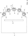
Figure 2 schematically illustrates a camera testing device according to an example embodiment. -
Figure 3 is a diagrammatic, perspective illustration of an example camera testing device embodiment. -
Figure 4 shows the embodiment ofFigure 3 from one side. -
Figure 5 shows the embodiment ofFigure 3 from an opposite side than that shown inFigure 4 . -
Figure 6 schematically illustrates selected portions of another camera testing system embodiment. -
Figure 7 is a diagrammatic, perspective illustration of the camera testing device of the embodiment shown inFigure 6 . -
Figure 8 schematically illustrates selected portions of another camera testing device embodiment. -
Figure 1 diagrammatically illustrates selected portions of acamera testing system 20. Anenvironmental chamber 22 is configured to establish at least one selected environmental condition, such as temperature or humidity, within theenvironmental chamber 22. One side of theenvironmental chamber 22 includes awindow 24. Acamera support 26 situated inside theenvironmental chamber 22 includes a plurality ofmounting locations 28 that are each configured for mounting acamera testing device 30. In this example, themounting locations 28 include slots that receive a portion of acamera testing device 30. While a singlecamera testing device 30 is shown for discussion purposes many situations will include multiplecamera testing devices 30 mounted on thecamera support 26. -
Figure 2 schematically illustrates portions of an examplecamera testing device 30. Thecamera testing device 30 includes a plurality ofoptic components Figure 2 for discussion purposes many embodiments will include more than five optic components. - The optic components 32-40 are in a preselected arrangement that places a
center 42 of each of the optic components 32-40 in a line of sight of a portion of a field of view of acamera 44, which is only partially represented inFigure 2 . Eachcenter 42 is aligned with a line of sight of a different, selected section of adetector portion 46 of thecamera 44. Thedetector portion 46 includes the pixels that establish or define the resolution of thecamera 44. Each of the selected sections includes at least one of the pixels of thedetector portion 46 and in many embodiments the sections include a group or cluster of pixels (e.g., 250 pixels).Figure 2 also shows alens 48 of thecamera 44, which is the only camera lens in this example. - In the illustrated arrangement of the optic components 32-40, the
center 42 of theoptic component 32 is aligned with the line of sight of afirst section 50 of thedetector portion 46, thecenter 42 of theoptic component 34 is aligned with asecond section 52, thecenter 42 of theoptic component 36 is aligned with athird section 54, thecenter 42 of theoptic component 38 is aligned with afourth section 56 and thecenter 42 of theoptic component 40 is aligned with afifth section 58. The selected sections 50-58 are chosen to test particular sections of thedetector portion 46, such as the center and near the edges of the field of view of thecamera 44. At least one image acquired using the camera with the optic components 32-40 in the predetermined arrangement provides information regarding the selected sections 50-58 of thedetector portion 46. - The optic components 32-40 are configured to make a target (not illustrated) appear further from the
camera 44 than the actual or physical distance between the target and thecamera 44. The optic components 32-40 are useful for testing the long range detection capabilities of thecamera 44 without requiring target placement far away from thecamera 44. The optic components 32-40 magnify the object space in the camera field of view. For example, a target may be placed within a meter of thecamera 44 to test or measure the camera performance for a target distance of more than fifty meters. - The
center 42 of each optic component 32-40 is coincident with or aligned with the line of sight of the respective sections 50-58 of thedetector portion 46 to minimize or eliminate any distortion or other aberrations introduced by the optic components 32-40. With smaller pixels in higher resolution cameras, the curvature potentially introduced along the outermost portions of a lens, such as the optic components 32-40, degrades the modulation transfer function (MTF) or the contrast image quality of thecamera 44. The strategic arrangement of thecenters 42 of the optic components 32-40, which centers the optic component with the field of view line of sight, is configured to provide the highest focus quality and the highest possible MTF of the selected sections 50-58 of thedetector portion 46. - Another feature of the arrangement of optic components in some embodiments is that respective targets for each of the selected sections of the
detector portion 46 may be situated in a single plane. This simplifies the testing equipment compared to requiring a structure that supports targets in multiple planes. -
Figures 3-5 illustrate an example embodiment of acamera testing device 30 that includes nine optic components. This embodiment includes aframe 60 that supports the optic components in the selected arrangement. A plurality ofarms 62 support theframe 60 relative to a housing of thecamera 44 to achieve the desired alignment between thecenters 42 of the optic components and the selected sections of the detector portion 46 (Figure 2 ) of thecamera 44. - As can be appreciated from
Figures 3-5 , the nine optic components include the optic components 32-40 as shown inFigure 2 and an additional fouroptic components camera 44, which has a relatively wide-angle field of view. For example, thecamera 44 may have a field of view that spans 150°. The positions and orientations of the optic components 64-70 facilitate testing the sections of the detector portion of thecamera 44 that would detect a target in the central and outer portions of the camera field of view. - The
frame 60 supports the optic components of the illustrated example embodiment in multiple planes and at various angles. The optic components are supported by theexample frame 60 in at least three different orientations. In an example embodiment, theframe 60 is a three-dimensional printed part, which allows for achieving the configuration of the desired arrangement of the optic components in a cost-effective manner. - One feature of the embodiment shown in
Figures 3-5 is a relativelycompact testing device 30 that fits within a reasonably sized packaging envelope (e.g., less than 200 cubic inches). This allows for positioning multiplecamera testing devices 30 on thecamera support 26 of theexample system 20 shown inFigure 1 . The illustrated example embodiment facilitates greater camera testing efficiencies by allowing for multiple cameras to be tested simultaneously within a singleenvironmental chamber 22. - The
frame 60 and thearms 62 are made of a polymer material that is capable of withstanding the environmental conditions established within an environmental chamber used for testing cameras that are useful on automotive vehicles. Theframe 60 andarms 62 are configured to be releasably connected with acamera 44 such that theframe 60 and the supported optic components are reusable for testing multiple cameras over time. -
Figures 6 and 7 show selected portions of another camera testing system 20'. In this embodiment, optic components are supported by aframe 80 that is situated outside of theenvironmental chamber 22. Anactuator 82, such as a robot arm, supports theframe 80 and is configured to move theframe 80 into a plurality of positions relative to thewindow 24 of theenvironmental chamber 22. Theactuator 82 facilitates moving theframe 80 and the supported optic components into various positions to testmultiple cameras 44 supported within theenvironmental chamber 22. - As best appreciated from
Figure 7 , theframe 80 in this example supports thirteen optic components and a plurality oftargets 84. Each of the optic components has an associatedtarget 84. Alighting device 86 associated with each of thetargets 84 is selectively controllable to emit a selected color or brightness of light for adjusting an appearance of the corresponding target. The individuallycontrollable lighting devices 86 allow for adjusting the appearance of any of thetargets 84 as may be needed for a particular testing procedure. For example, a particular camera being tested may only require nine targets and four of thelighting devices 86 may be controlled so that the corresponding targets do not appear and will not be detected by thecamera 44. Alternatively, different lighting effects may be used to accommodate for the manner in which thewindow 24 reduces light transmission depending on the angle of view to thetarget 84 and its associated optic component relative to acamera 44 that is being tested. - The
actuator 82 may move theframe 80 and the associated optic components and targets 84 into a variety of positions for testing the entire field of view of a single camera or multiple cameras over time. In some embodiments at least one image is acquired from the camera in each of the positions. -
Figure 8 schematically illustrates another example embodiment in which aframe 90 is part of theenvironmental chamber 22. In this example, theframe 90 is a door or closure panel of theenvironmental chamber 22. A plurality ofoptic components 92 are supported by theframe 90. Each of theoptic components 92 is housed in a vacuum sealed,insulated housing 94 that has awindow 96 on a side that faces the interior of theenvironmental chamber 22. The vacuum sealed,insulated housing 94 avoid condensation on theoptic components 92 that may otherwise be caused by differences in the environmental condition within thechamber 22 and the conditions outside of thechamber 22. The insulated effect of the vacuum sealedhousings 94 reduces or eliminates any need to control air flow immediately outside of theenvironmental chamber 22 to avoid condensation of theoptic components 92.Individual windows 96 of eachhousing 94 are configured to withstand exposure to the conditions in theenvironmental chamber 22. - With an embodiment like that shown in
Figure 8 , no large window is required for theenvironmental chamber 22 provided that theoptic components 92 are strategically placed for testing whatever camera configurations are of interest. Thecamera support 26 in the illustrated example embodiment includes an actuator (not illustrated) for moving one or more cameras within theenvironmental chamber 22 to achieve a desired alignment between theoptic components 92 and the camera. - The various features of the disclosed embodiments are not necessarily limited to the arrangements that are shown. Other combinations of the disclosed features are possible to realize additional or different embodiments.
- The preceding description is exemplary rather than limiting in nature. Variations and modifications to the disclosed examples may become apparent to those skilled in the art that do not necessarily depart from the essence of this invention. The scope of legal protection given to this invention can only be determined by studying the following claims.
Claims (15)
- A camera testing device (30), comprising:
a plurality of optic components (32-40) in a predetermined arrangement that places a center (42) of each of the optic components (32-40) in a position to be aligned with a line of sight of a respective, predetermined section (50-58) of a camera field of view when the plurality of optic components (32-40) are between the camera and at least one target. - The camera testing device (30) of claim 1, comprising a frame (60,80,90) that supports the plurality of optic components (32-40) in the predetermined arrangement.
- The camera testing device (30) of claim 2, wherein the frame (60,80,90) supports at least a first one of the optic components (32-40) in a first orientation, at least a second one of the optic components (32-40) in a second orientation that is different than the first orientation, and at least a third one of the optic components (32-40) in a third orientation that is different than the second orientation.
- The camera testing device (30) of claim 2 or 3, comprising a plurality of targets (84) and wherein the frame (60,80,90) supports the targets in a target arrangement corresponding to the predetermined arrangement of the optic components (32-40).
- The camera testing device (30) of claim 4, wherein the targets (84) include a source of light (86) that is selectively controllable to emit a selected color or brightness of light for adjusting an appearance of at least a selected one of the targets (84).
- The camera testing device (30) of claim 2, wherein
the frame (90) is part of an environmental chamber (22);
each of the optic components (32-40) comprises a sealed housing including a lens (92), a window (96) and a vacuum between the window and the lens; and
the frame (90) supports the optic components (32-40) with the window of each optic component facing toward one side of the frame (90) that is configured to face an interior of the environmental chamber (22). - The camera testing device (30) of claim 1, wherein each of the optic components (32-40) alters an appearance of a target in a manner that causes the target to appear farther from the optic component than an actual distance between the target and the optic component.
- A system (20), comprising:the camera testing device (30) of claim 1;an environmental chamber (22) configured to establish at least one preselected environmental condition;a camera support (26) situated within the environmental chamber (22); andat least one target that is detectable by at least one camera (44),wherein the camera testing device (30) is situated between the camera support (26) and the at least one target.
- The system (20) of claim 8, wherein
the camera testing device (30) is situated inside the environmental chamber (22);
the camera testing device (30) comprises an actuator (82) that is configured to move the plurality of optic components (32-40) into a plurality of positions relative to the camera support (26); and
the camera testing device (30) is situated outside the environmental chamber (22). - The system (20) of claim 8, wherein
the environmental chamber (22) includes at least one panel (90) between the camera support and the at least one target;
the plurality of optic components (32-40) are supported by the at least one panel (90);
each of the optic components (32-40) comprises a sealed housing (94) including a lens, a window and a vacuum between the window and the lens; and
the window of each optic component (92) faces toward an interior of the environmental chamber (22). - A method of testing a camera (44), the method comprising:arranging a plurality of optic components (32-40) in an arrangement that places a center (42) of each of the optic components (32-40) in a position to be aligned with a line of sight of a respective, predetermined section (50-58) of a camera field of view when the plurality of optic components (32-40) are between the camera (44) and at least one target; andacquiring at least one image of at least one target from the camera while the plurality of optic components (32-40) are in the arrangement.
- The method of claim 11, wherein
a frame (60,80,90) supports the plurality of optic components (32-40) in the arrangement with at least a first one of the optic components (32-40) in a first orientation, at least a second one of the optic components (32-40) in a second orientation that is different than the first orientation, and at least a third one of the optic components (32-40) in a third orientation that is different than the second orientation; and
the method comprises
moving the frame (60,80,90) into a plurality of positions and
acquiring at least one image from the camera with the frame (60,80,90) in each of the positions. - The method of claim 11, comprising supporting the optic components (92) on at least one panel (90) of an environmental chamber (22).
- The method of claim 11, comprising situating the optic components (32-40) within an environmental chamber (22).
- The method of claim 11, comprising using the optic components (32-40) to alter an appearance of a target in a manner that causes the target to appear farther from the optic component than an actual distance between the target and the optic component.
Applications Claiming Priority (1)
| Application Number | Priority Date | Filing Date | Title |
|---|---|---|---|
| US16/746,329 US11394955B2 (en) | 2020-01-17 | 2020-01-17 | Optics device for testing cameras useful on vehicles |
Publications (2)
| Publication Number | Publication Date |
|---|---|
| EP3851826A1 true EP3851826A1 (en) | 2021-07-21 |
| EP3851826B1 EP3851826B1 (en) | 2024-03-20 |
Family
ID=74184567
Family Applications (1)
| Application Number | Title | Priority Date | Filing Date |
|---|---|---|---|
| EP21151761.0A Active EP3851826B1 (en) | 2020-01-17 | 2021-01-15 | Optics device for testing cameras useful on vehicles |
Country Status (3)
| Country | Link |
|---|---|
| US (1) | US11394955B2 (en) |
| EP (1) | EP3851826B1 (en) |
| CN (1) | CN113141503B (en) |
Families Citing this family (2)
| Publication number | Priority date | Publication date | Assignee | Title |
|---|---|---|---|---|
| US11713614B2 (en) * | 2019-01-11 | 2023-08-01 | Sp Technology Co., Ltd. | Condensation prevention type transmission window for CMS module test chamber |
| DE102020125064A1 (en) * | 2020-09-25 | 2022-03-31 | Trioptics Gmbh | MTF test device and its use |
Citations (8)
| Publication number | Priority date | Publication date | Assignee | Title |
|---|---|---|---|---|
| US20110285857A1 (en) * | 2010-05-24 | 2011-11-24 | Fih (Hong Kong) Limited | Optical testing apparatus and testing method thereof |
| US20140152845A1 (en) * | 2011-05-19 | 2014-06-05 | Ulrich Seger | camera testing device and method for testing a camera |
| US20140204220A1 (en) * | 2011-07-05 | 2014-07-24 | Andreas Schmack | System and method for determining an imaging deviation of a camera |
| US20150138372A1 (en) * | 2012-01-05 | 2015-05-21 | Robert Bosch Gmbh | Device and method for measuring a camera |
| EP2924492A1 (en) * | 2014-03-27 | 2015-09-30 | Goodrich Corporation | Multiple collimator unit |
| US20170048517A1 (en) * | 2015-08-10 | 2017-02-16 | Oren Aharon | Mass production mtf testing machine |
| CN106502039A (en) * | 2016-12-08 | 2017-03-15 | 浙江舜宇光学有限公司 | Optical detection apparatus |
| US20180035109A1 (en) * | 2016-07-27 | 2018-02-01 | Arnold & Richter Cine Technik Gmbh & Co. Betriebs Kg | Object simulation unit for testing a camera objective and diagnostic system |
Family Cites Families (48)
| Publication number | Priority date | Publication date | Assignee | Title |
|---|---|---|---|---|
| US4732470A (en) * | 1986-05-22 | 1988-03-22 | The United States Of America As Represented By The Secretary Of The Army | Parallax error measurement device |
| US7893957B2 (en) * | 2002-08-28 | 2011-02-22 | Visual Intelligence, LP | Retinal array compound camera system |
| US7633611B2 (en) * | 2006-07-20 | 2009-12-15 | Aptina Imaging Corporation | Method and apparatus for testing imager devices using a center turning optic |
| US8988530B2 (en) * | 2008-03-18 | 2015-03-24 | Pictureflow Llc | System and method for measuring accuracy of focus |
| JP2011523538A (en) * | 2008-05-20 | 2011-08-11 | ペリカン イメージング コーポレイション | Image capture and processing using monolithic camera arrays with different types of imagers |
| WO2011063347A2 (en) * | 2009-11-20 | 2011-05-26 | Pelican Imaging Corporation | Capturing and processing of images using monolithic camera array with heterogeneous imagers |
| IL206689A (en) * | 2010-06-29 | 2015-09-24 | Israel Aerospace Ind Ltd | Line of sight stabilization system |
| US20120050024A1 (en) * | 2010-08-25 | 2012-03-01 | Delphi Technologies, Inc. | Vehicle camera system |
| US8686943B1 (en) * | 2011-05-13 | 2014-04-01 | Imimtek, Inc. | Two-dimensional method and system enabling three-dimensional user interaction with a device |
| KR101861823B1 (en) * | 2011-09-16 | 2018-05-29 | 삼성디스플레이 주식회사 | Testing apparatus for organic light emitting display apparatus, and manufacturing system for organic light emitting display apparatus |
| WO2014006500A2 (en) * | 2012-07-02 | 2014-01-09 | Agricam Ab | Camera housings, camera modules, and monitoring systems |
| US9270876B2 (en) * | 2013-01-05 | 2016-02-23 | The Lightco Inc. | Methods and apparatus for using multiple optical chains in parallel with multiple different exposure times |
| WO2014164909A1 (en) * | 2013-03-13 | 2014-10-09 | Pelican Imaging Corporation | Array camera architecture implementing quantum film sensors |
| US9392129B2 (en) * | 2013-03-15 | 2016-07-12 | John Castle Simmons | Light management for image and data control |
| EP2979445A4 (en) * | 2013-03-27 | 2016-08-10 | Bae Sys Inf & Elect Sys Integ | MULTI-SENSOR ELECTRO-OPTICAL FUSION-ZOOM WITH MULTIPLE FIELDS OF VISION |
| US10129469B2 (en) * | 2013-03-27 | 2018-11-13 | Bae Systems Information And Electronic Systems Integration Inc. | Passive infrared search and track sensor system |
| US9197816B2 (en) * | 2013-10-18 | 2015-11-24 | The Lightco Inc. | Zoom related methods and apparatus |
| US9467627B2 (en) * | 2013-10-26 | 2016-10-11 | The Lightco Inc. | Methods and apparatus for use with multiple optical chains |
| US9366838B2 (en) * | 2013-11-19 | 2016-06-14 | Corning Cable Systems Llc | Secure cable housing system for optical communication network |
| US20150241713A1 (en) * | 2014-02-21 | 2015-08-27 | The Lightco Inc. | Camera holder methods and apparatus |
| US20160280136A1 (en) * | 2014-03-05 | 2016-09-29 | Guy M. Besson | Active-tracking vehicular-based systems and methods for generating adaptive image |
| US9521319B2 (en) * | 2014-06-18 | 2016-12-13 | Pelican Imaging Corporation | Array cameras and array camera modules including spectral filters disposed outside of a constituent image sensor |
| DE102014212104A1 (en) * | 2014-06-24 | 2015-12-24 | Fraunhofer-Gesellschaft zur Förderung der angewandten Forschung e.V. | DEVICE AND METHOD FOR THE RELATIVE POSITIONING OF A MULTI-PAPER UROPTIK WITH SEVERAL OPTICAL CHANNELS RELATIVE TO AN IMAGE SENSOR |
| US9912864B2 (en) * | 2014-10-17 | 2018-03-06 | Light Labs Inc. | Methods and apparatus for using a camera device to support multiple modes of operation |
| EP3230776B1 (en) * | 2014-12-08 | 2021-05-26 | TRW Automotive U.S. LLC | Compact modular transfer function evaluation system |
| US9857584B2 (en) * | 2015-04-17 | 2018-01-02 | Light Labs Inc. | Camera device methods, apparatus and components |
| US10419655B2 (en) * | 2015-04-27 | 2019-09-17 | Snap-Aid Patents Ltd. | Estimating and using relative head pose and camera field-of-view |
| US10129483B2 (en) * | 2015-06-23 | 2018-11-13 | Light Labs Inc. | Methods and apparatus for implementing zoom using one or more moveable camera modules |
| DE102016111600B4 (en) * | 2015-06-26 | 2021-12-30 | Cognex Corporation | Lighting arrangement |
| US10491806B2 (en) * | 2015-08-03 | 2019-11-26 | Light Labs Inc. | Camera device control related methods and apparatus |
| US20170129402A1 (en) * | 2015-11-05 | 2017-05-11 | Delphi Technologies, Inc. | Camera With Light-Guide Array For Automated Vehicles |
| EP3166312B1 (en) * | 2015-11-06 | 2020-12-30 | Trioptics GmbH | Device and method for adjusting and/or calibrating a multi-camera module and use of such a device |
| US10732376B2 (en) * | 2015-12-02 | 2020-08-04 | Ningbo Sunny Opotech Co., Ltd. | Camera lens module and manufacturing method thereof |
| US9863866B2 (en) | 2015-12-14 | 2018-01-09 | Delphi Technologies, Inc. | Bi-directional air-curtain for cold testing a camera |
| US10353167B2 (en) * | 2016-02-29 | 2019-07-16 | Ningbo Sunny Opotech Co., Ltd. | Camera lens module with one or more optical lens modules and manufacturing method thereof |
| US10123120B2 (en) * | 2016-03-15 | 2018-11-06 | Bacch Laboratories, Inc. | Method and apparatus for providing 3D sound for surround sound configurations |
| US10306218B2 (en) * | 2016-03-22 | 2019-05-28 | Light Labs Inc. | Camera calibration apparatus and methods |
| US9798054B1 (en) * | 2016-03-30 | 2017-10-24 | Delphi Technologies, Inc. | Camera assembly for use on a vehicle |
| US20170290170A1 (en) * | 2016-03-30 | 2017-10-05 | Delphi Technologies, Inc. | Method Of Making A Camera For Use On A Vehicle |
| US10023120B2 (en) * | 2016-03-30 | 2018-07-17 | Delphi Technologies, Inc. | Multi-purpose camera device for use on a vehicle |
| US10139325B2 (en) * | 2016-04-21 | 2018-11-27 | The Boeing Company | System and method for evaluating bubble formation potential in a structure |
| US20180213220A1 (en) * | 2017-01-20 | 2018-07-26 | Ferrand D.E. Corley | Camera testing apparatus and method |
| US10465840B2 (en) * | 2017-03-22 | 2019-11-05 | Gopro, Inc. | Calibration for image stabilization mechanism |
| US10670858B2 (en) * | 2017-05-21 | 2020-06-02 | Light Labs Inc. | Methods and apparatus for maintaining and accurately determining the position of a moveable element |
| CN108924543B (en) * | 2017-06-23 | 2020-04-28 | 麦格纳电子(张家港)有限公司 | Optical test system and test method for vehicle-mounted camera |
| US10362203B2 (en) | 2017-08-14 | 2019-07-23 | Aptiv Technologies Limited | Camera assembly method with adhesive shrink offset based on individual lens characteristic |
| EP3527429B1 (en) * | 2018-02-15 | 2021-04-07 | Aptiv Technologies Limited | Module and support structure assembly |
| EP3534334B1 (en) | 2018-02-28 | 2022-04-13 | Aptiv Technologies Limited | Method for identification of characteristic points of a calibration pattern within a set of candidate points derived from an image of the calibration pattern |
-
2020
- 2020-01-17 US US16/746,329 patent/US11394955B2/en active Active
-
2021
- 2021-01-15 EP EP21151761.0A patent/EP3851826B1/en active Active
- 2021-01-15 CN CN202110054587.4A patent/CN113141503B/en active Active
Patent Citations (8)
| Publication number | Priority date | Publication date | Assignee | Title |
|---|---|---|---|---|
| US20110285857A1 (en) * | 2010-05-24 | 2011-11-24 | Fih (Hong Kong) Limited | Optical testing apparatus and testing method thereof |
| US20140152845A1 (en) * | 2011-05-19 | 2014-06-05 | Ulrich Seger | camera testing device and method for testing a camera |
| US20140204220A1 (en) * | 2011-07-05 | 2014-07-24 | Andreas Schmack | System and method for determining an imaging deviation of a camera |
| US20150138372A1 (en) * | 2012-01-05 | 2015-05-21 | Robert Bosch Gmbh | Device and method for measuring a camera |
| EP2924492A1 (en) * | 2014-03-27 | 2015-09-30 | Goodrich Corporation | Multiple collimator unit |
| US20170048517A1 (en) * | 2015-08-10 | 2017-02-16 | Oren Aharon | Mass production mtf testing machine |
| US20180035109A1 (en) * | 2016-07-27 | 2018-02-01 | Arnold & Richter Cine Technik Gmbh & Co. Betriebs Kg | Object simulation unit for testing a camera objective and diagnostic system |
| CN106502039A (en) * | 2016-12-08 | 2017-03-15 | 浙江舜宇光学有限公司 | Optical detection apparatus |
Also Published As
| Publication number | Publication date |
|---|---|
| CN113141503A (en) | 2021-07-20 |
| US11394955B2 (en) | 2022-07-19 |
| US20210227204A1 (en) | 2021-07-22 |
| CN113141503B (en) | 2024-10-11 |
| EP3851826B1 (en) | 2024-03-20 |
Similar Documents
| Publication | Publication Date | Title |
|---|---|---|
| CN110741278B (en) | LIDAR optical alignment system and method | |
| US10412286B2 (en) | Multicamera imaging system and method for measuring illumination | |
| US9213228B2 (en) | Device and method for measuring a camera | |
| US11394955B2 (en) | Optics device for testing cameras useful on vehicles | |
| US20100053414A1 (en) | Compound eye camera module | |
| US20090040312A1 (en) | Calibration apparatus and method thereof | |
| JP6327370B2 (en) | Measuring tool, calibration method, calibration apparatus, and program | |
| WO2018014014A1 (en) | Camera alignment and/or calibration methods and apparatus | |
| US6946647B1 (en) | Multicolor staring missile sensor system | |
| CN110891171B (en) | Test module for fixed focus camera module evaluation | |
| CN110235057A (en) | For determining the method for the deviation in the displaced path of varifocal optical system and for the method and image capturing device of correction | |
| WO2021024612A1 (en) | Method for correcting stereocamera and device for correcting stereocamera | |
| US6556284B1 (en) | System for measuring the luminance characteristics of objects, in particular objects with luminance dependent on emitting direction | |
| US7119969B1 (en) | Pixel matched camera optics | |
| CN118882528B (en) | A method for measuring the deployment angle of a folding rudder used in a high-speed wind tunnel | |
| IL167193A (en) | Method and system for determining optical distortion in a transparent medium | |
| US5204733A (en) | Apparatus for calibrating an optical instrument, and applications thereof | |
| US5200622A (en) | Self-checked optronic system of infra-red observation and laser designation pod including such a system | |
| EP4404554A1 (en) | Intrinsic parameter calibration system | |
| CN114607908B (en) | Adjusting mechanism and method relating to multi-camera positioning | |
| CN112067018B (en) | Multi-star simulator with ultra-long exit pupil distance for thermal vacuum test | |
| US4732470A (en) | Parallax error measurement device | |
| KR102854032B1 (en) | Sensing camera inspection equipment for vehicles accompanied by temperature testing | |
| GB2132049A (en) | Aligning two radiation sensors | |
| TWI858759B (en) | Panoramic surveillance device and surveillance system |
Legal Events
| Date | Code | Title | Description |
|---|---|---|---|
| PUAI | Public reference made under article 153(3) epc to a published international application that has entered the european phase |
Free format text: ORIGINAL CODE: 0009012 |
|
| STAA | Information on the status of an ep patent application or granted ep patent |
Free format text: STATUS: THE APPLICATION HAS BEEN PUBLISHED |
|
| AK | Designated contracting states |
Kind code of ref document: A1 Designated state(s): AL AT BE BG CH CY CZ DE DK EE ES FI FR GB GR HR HU IE IS IT LI LT LU LV MC MK MT NL NO PL PT RO RS SE SI SK SM TR |
|
| STAA | Information on the status of an ep patent application or granted ep patent |
Free format text: STATUS: REQUEST FOR EXAMINATION WAS MADE |
|
| 17P | Request for examination filed |
Effective date: 20220117 |
|
| RBV | Designated contracting states (corrected) |
Designated state(s): AL AT BE BG CH CY CZ DE DK EE ES FI FR GB GR HR HU IE IS IT LI LT LU LV MC MK MT NL NO PL PT RO RS SE SI SK SM TR |
|
| RAP3 | Party data changed (applicant data changed or rights of an application transferred) |
Owner name: APTIV TECHNOLOGIES LIMITED |
|
| GRAP | Despatch of communication of intention to grant a patent |
Free format text: ORIGINAL CODE: EPIDOSNIGR1 |
|
| STAA | Information on the status of an ep patent application or granted ep patent |
Free format text: STATUS: GRANT OF PATENT IS INTENDED |
|
| INTG | Intention to grant announced |
Effective date: 20231205 |
|
| GRAS | Grant fee paid |
Free format text: ORIGINAL CODE: EPIDOSNIGR3 |
|
| GRAA | (expected) grant |
Free format text: ORIGINAL CODE: 0009210 |
|
| STAA | Information on the status of an ep patent application or granted ep patent |
Free format text: STATUS: THE PATENT HAS BEEN GRANTED |
|
| AK | Designated contracting states |
Kind code of ref document: B1 Designated state(s): AL AT BE BG CH CY CZ DE DK EE ES FI FR GB GR HR HU IE IS IT LI LT LU LV MC MK MT NL NO PL PT RO RS SE SI SK SM TR |
|
| REG | Reference to a national code |
Ref country code: GB Ref legal event code: FG4D |
|
| REG | Reference to a national code |
Ref country code: CH Ref legal event code: EP |
|
| P01 | Opt-out of the competence of the unified patent court (upc) registered |
Effective date: 20240226 |
|
| REG | Reference to a national code |
Ref country code: IE Ref legal event code: FG4D |
|
| REG | Reference to a national code |
Ref country code: DE Ref legal event code: R096 Ref document number: 602021010527 Country of ref document: DE |
|
| PG25 | Lapsed in a contracting state [announced via postgrant information from national office to epo] |
Ref country code: LT Free format text: LAPSE BECAUSE OF FAILURE TO SUBMIT A TRANSLATION OF THE DESCRIPTION OR TO PAY THE FEE WITHIN THE PRESCRIBED TIME-LIMIT Effective date: 20240320 |
|
| REG | Reference to a national code |
Ref country code: LT Ref legal event code: MG9D |
|
| PG25 | Lapsed in a contracting state [announced via postgrant information from national office to epo] |
Ref country code: GR Free format text: LAPSE BECAUSE OF FAILURE TO SUBMIT A TRANSLATION OF THE DESCRIPTION OR TO PAY THE FEE WITHIN THE PRESCRIBED TIME-LIMIT Effective date: 20240621 |
|
| PG25 | Lapsed in a contracting state [announced via postgrant information from national office to epo] |
Ref country code: RS Free format text: LAPSE BECAUSE OF FAILURE TO SUBMIT A TRANSLATION OF THE DESCRIPTION OR TO PAY THE FEE WITHIN THE PRESCRIBED TIME-LIMIT Effective date: 20240620 Ref country code: HR Free format text: LAPSE BECAUSE OF FAILURE TO SUBMIT A TRANSLATION OF THE DESCRIPTION OR TO PAY THE FEE WITHIN THE PRESCRIBED TIME-LIMIT Effective date: 20240320 |
|
| REG | Reference to a national code |
Ref country code: NL Ref legal event code: MP Effective date: 20240320 |
|
| PG25 | Lapsed in a contracting state [announced via postgrant information from national office to epo] |
Ref country code: RS Free format text: LAPSE BECAUSE OF FAILURE TO SUBMIT A TRANSLATION OF THE DESCRIPTION OR TO PAY THE FEE WITHIN THE PRESCRIBED TIME-LIMIT Effective date: 20240620 Ref country code: NO Free format text: LAPSE BECAUSE OF FAILURE TO SUBMIT A TRANSLATION OF THE DESCRIPTION OR TO PAY THE FEE WITHIN THE PRESCRIBED TIME-LIMIT Effective date: 20240620 Ref country code: LT Free format text: LAPSE BECAUSE OF FAILURE TO SUBMIT A TRANSLATION OF THE DESCRIPTION OR TO PAY THE FEE WITHIN THE PRESCRIBED TIME-LIMIT Effective date: 20240320 Ref country code: HR Free format text: LAPSE BECAUSE OF FAILURE TO SUBMIT A TRANSLATION OF THE DESCRIPTION OR TO PAY THE FEE WITHIN THE PRESCRIBED TIME-LIMIT Effective date: 20240320 Ref country code: GR Free format text: LAPSE BECAUSE OF FAILURE TO SUBMIT A TRANSLATION OF THE DESCRIPTION OR TO PAY THE FEE WITHIN THE PRESCRIBED TIME-LIMIT Effective date: 20240621 Ref country code: FI Free format text: LAPSE BECAUSE OF FAILURE TO SUBMIT A TRANSLATION OF THE DESCRIPTION OR TO PAY THE FEE WITHIN THE PRESCRIBED TIME-LIMIT Effective date: 20240320 Ref country code: BG Free format text: LAPSE BECAUSE OF FAILURE TO SUBMIT A TRANSLATION OF THE DESCRIPTION OR TO PAY THE FEE WITHIN THE PRESCRIBED TIME-LIMIT Effective date: 20240320 |
|
| REG | Reference to a national code |
Ref country code: AT Ref legal event code: MK05 Ref document number: 1668222 Country of ref document: AT Kind code of ref document: T Effective date: 20240320 |
|
| PG25 | Lapsed in a contracting state [announced via postgrant information from national office to epo] |
Ref country code: SE Free format text: LAPSE BECAUSE OF FAILURE TO SUBMIT A TRANSLATION OF THE DESCRIPTION OR TO PAY THE FEE WITHIN THE PRESCRIBED TIME-LIMIT Effective date: 20240320 Ref country code: LV Free format text: LAPSE BECAUSE OF FAILURE TO SUBMIT A TRANSLATION OF THE DESCRIPTION OR TO PAY THE FEE WITHIN THE PRESCRIBED TIME-LIMIT Effective date: 20240320 |
|
| PG25 | Lapsed in a contracting state [announced via postgrant information from national office to epo] |
Ref country code: NL Free format text: LAPSE BECAUSE OF FAILURE TO SUBMIT A TRANSLATION OF THE DESCRIPTION OR TO PAY THE FEE WITHIN THE PRESCRIBED TIME-LIMIT Effective date: 20240320 |
|
| PG25 | Lapsed in a contracting state [announced via postgrant information from national office to epo] |
Ref country code: NL Free format text: LAPSE BECAUSE OF FAILURE TO SUBMIT A TRANSLATION OF THE DESCRIPTION OR TO PAY THE FEE WITHIN THE PRESCRIBED TIME-LIMIT Effective date: 20240320 |
|
| PG25 | Lapsed in a contracting state [announced via postgrant information from national office to epo] |
Ref country code: IS Free format text: LAPSE BECAUSE OF FAILURE TO SUBMIT A TRANSLATION OF THE DESCRIPTION OR TO PAY THE FEE WITHIN THE PRESCRIBED TIME-LIMIT Effective date: 20240720 |
|
| PG25 | Lapsed in a contracting state [announced via postgrant information from national office to epo] |
Ref country code: SM Free format text: LAPSE BECAUSE OF FAILURE TO SUBMIT A TRANSLATION OF THE DESCRIPTION OR TO PAY THE FEE WITHIN THE PRESCRIBED TIME-LIMIT Effective date: 20240320 Ref country code: PT Free format text: LAPSE BECAUSE OF FAILURE TO SUBMIT A TRANSLATION OF THE DESCRIPTION OR TO PAY THE FEE WITHIN THE PRESCRIBED TIME-LIMIT Effective date: 20240722 |
|
| PG25 | Lapsed in a contracting state [announced via postgrant information from national office to epo] |
Ref country code: ES Free format text: LAPSE BECAUSE OF FAILURE TO SUBMIT A TRANSLATION OF THE DESCRIPTION OR TO PAY THE FEE WITHIN THE PRESCRIBED TIME-LIMIT Effective date: 20240320 |
|
| PG25 | Lapsed in a contracting state [announced via postgrant information from national office to epo] |
Ref country code: CZ Free format text: LAPSE BECAUSE OF FAILURE TO SUBMIT A TRANSLATION OF THE DESCRIPTION OR TO PAY THE FEE WITHIN THE PRESCRIBED TIME-LIMIT Effective date: 20240320 Ref country code: EE Free format text: LAPSE BECAUSE OF FAILURE TO SUBMIT A TRANSLATION OF THE DESCRIPTION OR TO PAY THE FEE WITHIN THE PRESCRIBED TIME-LIMIT Effective date: 20240320 |
|
| PG25 | Lapsed in a contracting state [announced via postgrant information from national office to epo] |
Ref country code: AT Free format text: LAPSE BECAUSE OF FAILURE TO SUBMIT A TRANSLATION OF THE DESCRIPTION OR TO PAY THE FEE WITHIN THE PRESCRIBED TIME-LIMIT Effective date: 20240320 |
|
| PG25 | Lapsed in a contracting state [announced via postgrant information from national office to epo] |
Ref country code: PL Free format text: LAPSE BECAUSE OF FAILURE TO SUBMIT A TRANSLATION OF THE DESCRIPTION OR TO PAY THE FEE WITHIN THE PRESCRIBED TIME-LIMIT Effective date: 20240320 |
|
| PG25 | Lapsed in a contracting state [announced via postgrant information from national office to epo] |
Ref country code: SK Free format text: LAPSE BECAUSE OF FAILURE TO SUBMIT A TRANSLATION OF THE DESCRIPTION OR TO PAY THE FEE WITHIN THE PRESCRIBED TIME-LIMIT Effective date: 20240320 |
|
| PG25 | Lapsed in a contracting state [announced via postgrant information from national office to epo] |
Ref country code: SM Free format text: LAPSE BECAUSE OF FAILURE TO SUBMIT A TRANSLATION OF THE DESCRIPTION OR TO PAY THE FEE WITHIN THE PRESCRIBED TIME-LIMIT Effective date: 20240320 Ref country code: SK Free format text: LAPSE BECAUSE OF FAILURE TO SUBMIT A TRANSLATION OF THE DESCRIPTION OR TO PAY THE FEE WITHIN THE PRESCRIBED TIME-LIMIT Effective date: 20240320 Ref country code: RO Free format text: LAPSE BECAUSE OF FAILURE TO SUBMIT A TRANSLATION OF THE DESCRIPTION OR TO PAY THE FEE WITHIN THE PRESCRIBED TIME-LIMIT Effective date: 20240320 Ref country code: PT Free format text: LAPSE BECAUSE OF FAILURE TO SUBMIT A TRANSLATION OF THE DESCRIPTION OR TO PAY THE FEE WITHIN THE PRESCRIBED TIME-LIMIT Effective date: 20240722 Ref country code: PL Free format text: LAPSE BECAUSE OF FAILURE TO SUBMIT A TRANSLATION OF THE DESCRIPTION OR TO PAY THE FEE WITHIN THE PRESCRIBED TIME-LIMIT Effective date: 20240320 Ref country code: IS Free format text: LAPSE BECAUSE OF FAILURE TO SUBMIT A TRANSLATION OF THE DESCRIPTION OR TO PAY THE FEE WITHIN THE PRESCRIBED TIME-LIMIT Effective date: 20240720 Ref country code: ES Free format text: LAPSE BECAUSE OF FAILURE TO SUBMIT A TRANSLATION OF THE DESCRIPTION OR TO PAY THE FEE WITHIN THE PRESCRIBED TIME-LIMIT Effective date: 20240320 Ref country code: EE Free format text: LAPSE BECAUSE OF FAILURE TO SUBMIT A TRANSLATION OF THE DESCRIPTION OR TO PAY THE FEE WITHIN THE PRESCRIBED TIME-LIMIT Effective date: 20240320 Ref country code: CZ Free format text: LAPSE BECAUSE OF FAILURE TO SUBMIT A TRANSLATION OF THE DESCRIPTION OR TO PAY THE FEE WITHIN THE PRESCRIBED TIME-LIMIT Effective date: 20240320 Ref country code: AT Free format text: LAPSE BECAUSE OF FAILURE TO SUBMIT A TRANSLATION OF THE DESCRIPTION OR TO PAY THE FEE WITHIN THE PRESCRIBED TIME-LIMIT Effective date: 20240320 |
|
| PG25 | Lapsed in a contracting state [announced via postgrant information from national office to epo] |
Ref country code: IT Free format text: LAPSE BECAUSE OF FAILURE TO SUBMIT A TRANSLATION OF THE DESCRIPTION OR TO PAY THE FEE WITHIN THE PRESCRIBED TIME-LIMIT Effective date: 20240320 |
|
| REG | Reference to a national code |
Ref country code: DE Ref legal event code: R097 Ref document number: 602021010527 Country of ref document: DE |
|
| PG25 | Lapsed in a contracting state [announced via postgrant information from national office to epo] |
Ref country code: IT Free format text: LAPSE BECAUSE OF FAILURE TO SUBMIT A TRANSLATION OF THE DESCRIPTION OR TO PAY THE FEE WITHIN THE PRESCRIBED TIME-LIMIT Effective date: 20240320 |
|
| PG25 | Lapsed in a contracting state [announced via postgrant information from national office to epo] |
Ref country code: DK Free format text: LAPSE BECAUSE OF FAILURE TO SUBMIT A TRANSLATION OF THE DESCRIPTION OR TO PAY THE FEE WITHIN THE PRESCRIBED TIME-LIMIT Effective date: 20240320 |
|
| PLBE | No opposition filed within time limit |
Free format text: ORIGINAL CODE: 0009261 |
|
| STAA | Information on the status of an ep patent application or granted ep patent |
Free format text: STATUS: NO OPPOSITION FILED WITHIN TIME LIMIT |
|
| PG25 | Lapsed in a contracting state [announced via postgrant information from national office to epo] |
Ref country code: DK Free format text: LAPSE BECAUSE OF FAILURE TO SUBMIT A TRANSLATION OF THE DESCRIPTION OR TO PAY THE FEE WITHIN THE PRESCRIBED TIME-LIMIT Effective date: 20240320 |
|
| 26N | No opposition filed |
Effective date: 20241223 |
|
| PG25 | Lapsed in a contracting state [announced via postgrant information from national office to epo] |
Ref country code: SI Free format text: LAPSE BECAUSE OF FAILURE TO SUBMIT A TRANSLATION OF THE DESCRIPTION OR TO PAY THE FEE WITHIN THE PRESCRIBED TIME-LIMIT Effective date: 20240320 |
|
| REG | Reference to a national code |
Ref country code: DE Ref legal event code: R081 Ref document number: 602021010527 Country of ref document: DE Owner name: APTIV TECHNOLOGIES AG, CH Free format text: FORMER OWNER: APTIV TECHNOLOGIES LIMITED, ST. MICHAEL, BB |
|
| REG | Reference to a national code |
Ref country code: CH Ref legal event code: PL |
|
| PG25 | Lapsed in a contracting state [announced via postgrant information from national office to epo] |
Ref country code: MC Free format text: LAPSE BECAUSE OF FAILURE TO SUBMIT A TRANSLATION OF THE DESCRIPTION OR TO PAY THE FEE WITHIN THE PRESCRIBED TIME-LIMIT Effective date: 20240320 Ref country code: LU Free format text: LAPSE BECAUSE OF NON-PAYMENT OF DUE FEES Effective date: 20250115 |
|
| PG25 | Lapsed in a contracting state [announced via postgrant information from national office to epo] |
Ref country code: BE Free format text: LAPSE BECAUSE OF NON-PAYMENT OF DUE FEES Effective date: 20250131 |
|
| PG25 | Lapsed in a contracting state [announced via postgrant information from national office to epo] |
Ref country code: CH Free format text: LAPSE BECAUSE OF NON-PAYMENT OF DUE FEES Effective date: 20250131 |
|
| REG | Reference to a national code |
Ref country code: BE Ref legal event code: MM Effective date: 20250131 |
|
| PGFP | Annual fee paid to national office [announced via postgrant information from national office to epo] |
Ref country code: GB Payment date: 20251210 Year of fee payment: 6 |
|
| PGFP | Annual fee paid to national office [announced via postgrant information from national office to epo] |
Ref country code: FR Payment date: 20251202 Year of fee payment: 6 |
|
| PG25 | Lapsed in a contracting state [announced via postgrant information from national office to epo] |
Ref country code: IE Free format text: LAPSE BECAUSE OF NON-PAYMENT OF DUE FEES Effective date: 20250115 |
|
| PGFP | Annual fee paid to national office [announced via postgrant information from national office to epo] |
Ref country code: DE Payment date: 20251217 Year of fee payment: 6 |