EP3851795A1 - Chip-scale gyrometric apparatus - Google Patents
Chip-scale gyrometric apparatus Download PDFInfo
- Publication number
- EP3851795A1 EP3851795A1 EP21152175.2A EP21152175A EP3851795A1 EP 3851795 A1 EP3851795 A1 EP 3851795A1 EP 21152175 A EP21152175 A EP 21152175A EP 3851795 A1 EP3851795 A1 EP 3851795A1
- Authority
- EP
- European Patent Office
- Prior art keywords
- signal
- scale
- chip
- coil
- gyrometric
- Prior art date
- Legal status (The legal status is an assumption and is not a legal conclusion. Google has not performed a legal analysis and makes no representation as to the accuracy of the status listed.)
- Granted
Links
Images



Classifications
-
- G—PHYSICS
- G01—MEASURING; TESTING
- G01C—MEASURING DISTANCES, LEVELS OR BEARINGS; SURVEYING; NAVIGATION; GYROSCOPIC INSTRUMENTS; PHOTOGRAMMETRY OR VIDEOGRAMMETRY
- G01C19/00—Gyroscopes; Turn-sensitive devices using vibrating masses; Turn-sensitive devices without moving masses; Measuring angular rate using gyroscopic effects
- G01C19/58—Turn-sensitive devices without moving masses
- G01C19/64—Gyrometers using the Sagnac effect, i.e. rotation-induced shifts between counter-rotating electromagnetic beams
-
- G—PHYSICS
- G01—MEASURING; TESTING
- G01C—MEASURING DISTANCES, LEVELS OR BEARINGS; SURVEYING; NAVIGATION; GYROSCOPIC INSTRUMENTS; PHOTOGRAMMETRY OR VIDEOGRAMMETRY
- G01C19/00—Gyroscopes; Turn-sensitive devices using vibrating masses; Turn-sensitive devices without moving masses; Measuring angular rate using gyroscopic effects
- G01C19/56—Turn-sensitive devices using vibrating masses, e.g. vibratory angular rate sensors based on Coriolis forces
- G01C19/567—Turn-sensitive devices using vibrating masses, e.g. vibratory angular rate sensors based on Coriolis forces using the phase shift of a vibration node or antinode
- G01C19/5691—Turn-sensitive devices using vibrating masses, e.g. vibratory angular rate sensors based on Coriolis forces using the phase shift of a vibration node or antinode of essentially three-dimensional [3D] vibrators, e.g. wine glass-type vibrators
-
- G—PHYSICS
- G01—MEASURING; TESTING
- G01S—RADIO DIRECTION-FINDING; RADIO NAVIGATION; DETERMINING DISTANCE OR VELOCITY BY USE OF RADIO WAVES; LOCATING OR PRESENCE-DETECTING BY USE OF THE REFLECTION OR RERADIATION OF RADIO WAVES; ANALOGOUS ARRANGEMENTS USING OTHER WAVES
- G01S19/00—Satellite radio beacon positioning systems; Determining position, velocity or attitude using signals transmitted by such systems
- G01S19/38—Determining a navigation solution using signals transmitted by a satellite radio beacon positioning system
- G01S19/39—Determining a navigation solution using signals transmitted by a satellite radio beacon positioning system the satellite radio beacon positioning system transmitting time-stamped messages, e.g. GPS [Global Positioning System], GLONASS [Global Orbiting Navigation Satellite System] or GALILEO
- G01S19/393—Trajectory determination or predictive tracking, e.g. Kalman filtering
-
- G—PHYSICS
- G01—MEASURING; TESTING
- G01S—RADIO DIRECTION-FINDING; RADIO NAVIGATION; DETERMINING DISTANCE OR VELOCITY BY USE OF RADIO WAVES; LOCATING OR PRESENCE-DETECTING BY USE OF THE REFLECTION OR RERADIATION OF RADIO WAVES; ANALOGOUS ARRANGEMENTS USING OTHER WAVES
- G01S19/00—Satellite radio beacon positioning systems; Determining position, velocity or attitude using signals transmitted by such systems
- G01S19/38—Determining a navigation solution using signals transmitted by a satellite radio beacon positioning system
- G01S19/39—Determining a navigation solution using signals transmitted by a satellite radio beacon positioning system the satellite radio beacon positioning system transmitting time-stamped messages, e.g. GPS [Global Positioning System], GLONASS [Global Orbiting Navigation Satellite System] or GALILEO
- G01S19/42—Determining position
- G01S19/45—Determining position by combining measurements of signals from the satellite radio beacon positioning system with a supplementary measurement
- G01S19/46—Determining position by combining measurements of signals from the satellite radio beacon positioning system with a supplementary measurement the supplementary measurement being of a radio-wave signal type
-
- G—PHYSICS
- G01—MEASURING; TESTING
- G01S—RADIO DIRECTION-FINDING; RADIO NAVIGATION; DETERMINING DISTANCE OR VELOCITY BY USE OF RADIO WAVES; LOCATING OR PRESENCE-DETECTING BY USE OF THE REFLECTION OR RERADIATION OF RADIO WAVES; ANALOGOUS ARRANGEMENTS USING OTHER WAVES
- G01S19/00—Satellite radio beacon positioning systems; Determining position, velocity or attitude using signals transmitted by such systems
- G01S19/38—Determining a navigation solution using signals transmitted by a satellite radio beacon positioning system
- G01S19/39—Determining a navigation solution using signals transmitted by a satellite radio beacon positioning system the satellite radio beacon positioning system transmitting time-stamped messages, e.g. GPS [Global Positioning System], GLONASS [Global Orbiting Navigation Satellite System] or GALILEO
- G01S19/42—Determining position
- G01S19/45—Determining position by combining measurements of signals from the satellite radio beacon positioning system with a supplementary measurement
- G01S19/47—Determining position by combining measurements of signals from the satellite radio beacon positioning system with a supplementary measurement the supplementary measurement being an inertial measurement, e.g. tightly coupled inertial
Definitions
- the subject matter disclosed in the instant application is directed generally to positioning systems and more particularly to gyrometric hardware.
- Trusted systems may require additional hardware to verify trust in external components or functions.
- size, weight, power, and cost (SWaPC)-constrained navigation systems may require small form factor hardware to provide a check against external measurements originating from other assemblies, e.g., absolute or inertial positioning systems.
- SWaPC size, weight, power, and cost
- chip-scale solutions are currently available for absolute positioning (e.g., Global Positioning System (GPS) and other satellite-based navigational systems) or relative positioning solutions (e.g. inertial measurement units (IMU)), there is no equivalent solution for gyrometry or gyroscopy.
- GPS Global Positioning System
- IMU inertial measurement units
- the chip-scale gyrometric apparatus includes a dielectric substrate and an antenna element attached thereto for receiving an inbound signal having an initial phase.
- the apparatus includes a splitter for splitting the inbound signal into two equivalent signals.
- the apparatus includes two coils connected to the splitter; the first coil carries one of the split signals in a clockwise (CW) path relative to a rotational axis and the second coil carries the other split signal in a counterclockwise (CCW) path relative to the same rotational axis.
- CW clockwise
- CCW counterclockwise
- the apparatus includes an integrated circuit (IC) on the substrate and connected to the first and second coils; the IC measures a phase shift between the first and second signals (having a common initial phase) based on their respective CW and CCW paths and determines, based on the measured phase shift, a degree of rotation relative to the rotational axis common to the two coils.
- IC integrated circuit
- a multi-axis chip-scale gyrometric apparatus includes at least two dielectric substrates, each substrate defining a plane and associated with a rotational axis.
- a gyrometric assembly is attached to each substrate, each gyrometric assembly including an antenna element attached thereto for receiving an inbound signal having an initial phase.
- Each gyrometric assembly includes a splitter for splitting the inbound signal into two equivalent signals.
- Each gyrometric assembly includes two coils connected to the splitter; the first coil carries one of the split signals in a clockwise (CW) path relative to a rotational axis and the second coil carries the other split signal in a counterclockwise (CCW) path relative to the same rotational axis.
- CW clockwise
- CCW counterclockwise
- Each gyrometric assembly includes an integrated circuit (IC) on the substrate and connected to the first and second coils; each IC measures a phase shift between the first and second signals (having a common initial phase) based on their respective CW and CCW paths and determines, based on the measured phase shift, a degree of rotation relative to the rotational axis (for each of multiple rotational axes, e.g., x/y/z, pitch/roll/yaw).
- IC integrated circuit
- a letter following a reference numeral is intended to reference an embodiment of the feature or element that may be similar, but not necessarily identical, to a previously described element or feature bearing the same reference numeral (e.g., 1, 1a, 1b).
- reference numeral e.g. 1, 1a, 1b
- Such shorthand notations are used for purposes of convenience only and should not be construed to limit the disclosure in any way unless expressly stated to the contrary.
- any reference to “one embodiment” or “some embodiments” means that a particular element, feature, structure, or characteristic described in connection with the embodiment is included in at least one embodiment disclosed herein.
- the appearances of the phrase “in some embodiments” in various places in the specification are not necessarily all referring to the same embodiment, and embodiments may include one or more of the features expressly described or inherently present herein, or any combination or sub-combination of two or more such features, along with any other features which may not necessarily be expressly described or inherently present in the instant disclosure.
- the chip-scale gyrometric assembly may include a chip-scale dielectric substrate 102 (e.g., 4 inches (10 cm) or less in diameter), an integrated circuit 104 (IC), clockwise (CW) coil 106, and counterclockwise (CCW) coil 108.
- a chip-scale dielectric substrate 102 e.g., 4 inches (10 cm) or less in diameter
- IC integrated circuit
- CW clockwise
- CCW counterclockwise
- the chip-scale gyrometric assembly 100 may split a sourced signal into two separate coils, e.g., the CW coil 106 and CCW coil 108.
- each split signal may originate with an initial phase consistent with that of the sourced signal.
- One split signal 110a may travel clockwise through the CW coil 106 while the other split signal 110b travels counterclockwise through the CCW coil 108 in the same plane (e.g., relative to a rotational axis 112 perpendicular to the plane of the substrate 102 and of the CW and CCW coils).
- the CW coil 106 and CCW coil 108 may be wire coils attached to the substrate 102, through which the split inbound radio frequency (RF) signals 110a-b travel in CW and CCW directions respectively.
- the inbound signal and split signals 110a-b may be photonic or optical signals or carrier waves, and the CW and CCW coils 106, 108 fashioned of optical fibers or any like optical medium.
- the chip-scale gyrometric assembly 100 may utilize interferometric techniques to monitor the interference patterns generated by the superimposed split signals 110a-b traveling through the CW coil 106 and CCW coil 108.
- the respective rotation of the CW and CCW coils 106, 108 around the rotational axis 112 may result in a phase shift on the part of the signals traveling through the CW and CCW coils (e.g., relative to the initial phase of the inbound signal or to each other).
- phase shifts may be associated with a very small amount of rotation.
- the CW and CCW coils 106, 108 may be of sufficient length to provide, given a chip-scale substrate 102 and the correspondingly small amount of rotation around the rotational axis 112, a measurable phase shift between the split signals 110a-b.
- the chip-scale gyrometric assembly 100 may incorporate multilayer loops of CW and CCW coils 106, 108 incorporating hundreds of loops of submicron thickness above the IC 104.
- the IC 104 may incorporate internal transmitter and receiver circuitry capable of detecting the phase shift between the CW and CCW coils 106, 108 and determining, based on the measured phase shift, a degree of rotation relative to the rotational axis 112.
- the CW and CCW coils 106, 108 may be otherwise positioned or disposed with respect to the substrate 102 (e.g., side by side as opposed to overlapping (as shown by FIGS. 1 and 2 ), while still sharing a common rotational axis 110).
- the rotational axis 112a may be only substantially perpendicular, rather than precisely perpendicular, to the plane of the substrate 102; provided the rotational axis 112a is common to the CW and CCW coils 106, 108, the IC 104 may mathematically correct for any deviations from a 90-degree precise perpendicularity between the rotational axis 112a and the plane of the substrate 102.
- the chip-scale gyrometric apparatus 100a may be implemented and may function similarly to the chip-scale gyrometric apparatus 100 of FIGS. 1 and 2 , except that the chip-scale gyrometric apparatus 100a may include antenna elements 302, signal splitters 304, and analog-digital converters 306 (ADC).
- ADC analog-digital converters
- the chip-scale gyrometric apparatus 100a may receive the source signal 308 via the antenna elements 302.
- the source signal 308 may be split by the signal splitters 304 into identical split signals 110a-b of shared phase.
- the split signals 110a-b travel (in respective CW and CCW directions) through the CW and CCW coils 106, 108, the relative phase of the split signals 110a-b may shift, such that the IC 104 may detect (310) the phase of the split signals at the terminal end of the CW and CCW coils.
- the detected phases of the split signals 110a-b may be digitized via ADCs 306 and compared (e.g., via comparators 312 or similar circuitry) to determine a relative phase shift from which a degree of rotation (314) may be calculated.
- the determined degree of rotation 314 may be fed into other components of the IC 104.
- the determined degree of rotation 314 may be forwarded to Kalman filters 316, e.g., to facilitate estimation or prediction of future rotation.
- the degree of rotation 314 (relative to a particular rotational axis (112, FIG. 1 ) may be forwarded for use as a partial check for a positioning system integrated into the IC 104, e.g., a satellite-based absolute positioning system 318 (e.g., GPS or other GNSS-based satellite navigational systems) or inertial measurement unit 320 (IMU).
- a satellite-based absolute positioning system 318 e.g., GPS or other GNSS-based satellite navigational systems
- IMU inertial measurement unit 320
- the chip-scale gyrometric assembly 100b may be implemented and may function similarly to the chip-scale gyrometric assemblies 100, 100a of FIGS. 1 through 3 , except that the chip-scale gyrometric assembly 100b may incorporate an interposer layer 402.
- the CW and CCW coils 106, 108 may be positioned on opposing faces of the interposer layer 402 and interface with the IC 104 via the interposer, while sharing a common rotational axis 112.
- the IC 104 may be fully or partially embedded in a cavity within the interposer layer 402.
- the multiaxis chip-scale gyrometric apparatus 500 may be implemented and may function similarly to the chip-scale gyrometric assemblies 100, 100a-b of FIGS. 1 through 4B , except that the multiaxis chip-scale gyrometric apparatus 500 may incorporate multiple gyrometric assemblies 100c-e, each individual assembly 100c-e similar to the chip-scale gyrometric assemblies 100, 100a-b but configured to determine a degree of rotation (314, FIG. 3 ) with respect to mutually perpendicular rotational axes 112b-d.
- the multiaxis chip-scale gyrometric apparatus 500 may incorporate two gyrometric assemblies 100c-d corresponding to two rotational axes 112b-c.
- the multiaxis chip-scale gyrometric apparatus 500 may determine changes in rotational orientation relative to the longitudinal and lateral axes (e.g., rotational axes 112b-d) as well as a vertical orz-axis (e.g., rotational axis 112d; via the chip-scale gyrometric assembly 100e), e.g., for aircraft-based implementation.
- the mutually perpendicular substrates 102a-c of the multiaxis chip-scale gyrometric apparatus 500 may be fashioned of a single flexible circuit card assembly folded into the mutually perpendicular orientations shown by FIG. 5 and molded into a single package, e.g., whereby the individual chip-scale gyrometric assemblies 100c-e share common antenna elements (302, FIG. 3 ) and/or ICs (104, FIG. 3 ).
- the mutually perpendicular rotational axes 112b-d may be substantially perpendicular, rather than precisely perpendicular as shown by FIG. 5 .
- one or more rotational axes (112e) may not be aligned at precisely 90 degrees to the other mutually perpendicular rotational axes 112b-c, or to its corresponding substrate 102c.
- the IC 104 of the corresponding chip-scale gyrometric assembly 100e may mathematically correct for any deviations from precise perpendicularity on the part of the rotational axis 112e or the substrate 102c, provided the rotational axis 112e is common to the CW and CCW coils 106, 108 of the chip-scale gyrometric assembly.
- each chip-scale gyrometric assembly 100c-e may have its own IC 104, the separate ICs in communication with each other.
- embodiments of the methods disclosed herein may include one or more of the steps described herein. Further, such steps may be carried out in any desired order and two or more of the steps may be carried out simultaneously with one another. Two or more of the steps disclosed herein may be combined in a single step, and in some embodiments, one or more of the steps may be carried out as two or more sub-steps. Further, other steps or sub-steps may be carried in addition to, or as substitutes to one or more of the steps disclosed herein.
Landscapes
- Engineering & Computer Science (AREA)
- Radar, Positioning & Navigation (AREA)
- Remote Sensing (AREA)
- Physics & Mathematics (AREA)
- General Physics & Mathematics (AREA)
- Computer Networks & Wireless Communication (AREA)
- Electromagnetism (AREA)
- Power Engineering (AREA)
- Gyroscopes (AREA)
Abstract
Description
- The subject matter disclosed in the instant application is directed generally to positioning systems and more particularly to gyrometric hardware.
- Trusted systems may require additional hardware to verify trust in external components or functions. For example, size, weight, power, and cost (SWaPC)-constrained navigation systems may require small form factor hardware to provide a check against external measurements originating from other assemblies, e.g., absolute or inertial positioning systems. Further, while chip-scale solutions are currently available for absolute positioning (e.g., Global Positioning System (GPS) and other satellite-based navigational systems) or relative positioning solutions (e.g. inertial measurement units (IMU)), there is no equivalent solution for gyrometry or gyroscopy.
- A chip-scale gyrometric apparatus is disclosed. In embodiments, the chip-scale gyrometric apparatus includes a dielectric substrate and an antenna element attached thereto for receiving an inbound signal having an initial phase. The apparatus includes a splitter for splitting the inbound signal into two equivalent signals. The apparatus includes two coils connected to the splitter; the first coil carries one of the split signals in a clockwise (CW) path relative to a rotational axis and the second coil carries the other split signal in a counterclockwise (CCW) path relative to the same rotational axis. The apparatus includes an integrated circuit (IC) on the substrate and connected to the first and second coils; the IC measures a phase shift between the first and second signals (having a common initial phase) based on their respective CW and CCW paths and determines, based on the measured phase shift, a degree of rotation relative to the rotational axis common to the two coils.
- A multi-axis chip-scale gyrometric apparatus is also disclosed. In embodiments, the multi-axis apparatus includes at least two dielectric substrates, each substrate defining a plane and associated with a rotational axis. A gyrometric assembly is attached to each substrate, each gyrometric assembly including an antenna element attached thereto for receiving an inbound signal having an initial phase. Each gyrometric assembly includes a splitter for splitting the inbound signal into two equivalent signals. Each gyrometric assembly includes two coils connected to the splitter; the first coil carries one of the split signals in a clockwise (CW) path relative to a rotational axis and the second coil carries the other split signal in a counterclockwise (CCW) path relative to the same rotational axis. Each gyrometric assembly includes an integrated circuit (IC) on the substrate and connected to the first and second coils; each IC measures a phase shift between the first and second signals (having a common initial phase) based on their respective CW and CCW paths and determines, based on the measured phase shift, a degree of rotation relative to the rotational axis (for each of multiple rotational axes, e.g., x/y/z, pitch/roll/yaw).
- This Summary is provided solely as an introduction to subject matter that is fully described in the Detailed Description and Drawings. The Summary should not be considered to describe essential features nor be used to determine the scope of the Claims. Moreover, it is to be understood that both the foregoing Summary and the following Detailed Description are example and explanatory only and are not necessarily restrictive of the subject matter claimed.
- The detailed description is described with reference to the accompanying figures. The use of the same reference numbers in different instances in the description and the figures may indicate similar or identical items. Various embodiments or examples ("examples") of the present disclosure are disclosed in the following detailed description and the accompanying drawings. The drawings are not necessarily to scale. In general, operations of disclosed processes may be performed in an arbitrary order, unless otherwise provided in the claims. In the drawings:
-
FIGS. 1 and 2 are respectively profile and overhead views of a chip-scale gyrometric apparatus in accordance with example embodiments of this disclosure; -
FIG. 3 is a block diagram illustrating the chip-scale gyrometric apparatus ofFIGS. 1 and 2 ; -
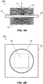
FIGS. 4A and 4B are respectively profile and overhead views of the chip-scale gyrometric apparatus ofFIGS. 1 and 2 ; and -
FIG. 5 is an isometric view of a chip-scale gyrometric apparatus according to example embodiments of this disclosure. - Before explaining one or more embodiments of the disclosure in detail, it is to be understood that the embodiments are not limited in their application to the details of construction and the arrangement of the components or steps or methodologies set forth in the following description or illustrated in the drawings. In the following detailed description of embodiments, numerous specific details may be set forth in order to provide a more thorough understanding of the disclosure. However, it will be apparent to one of ordinary skill in the art having the benefit of the instant disclosure that the embodiments disclosed herein may be practiced without some of these specific details. In other instances, well-known features may not be described in detail to avoid unnecessarily complicating the instant disclosure.
- As used herein a letter following a reference numeral is intended to reference an embodiment of the feature or element that may be similar, but not necessarily identical, to a previously described element or feature bearing the same reference numeral (e.g., 1, 1a, 1b). Such shorthand notations are used for purposes of convenience only and should not be construed to limit the disclosure in any way unless expressly stated to the contrary.
- Further, unless expressly stated to the contrary, "or" refers to an inclusive or and not to an exclusive or. For example, a condition A or B is satisfied by any one of the following: A is true (or present) and B is false (or not present), A is false (or not present) and B is true (or present), and both A and B are true (or present).
- In addition, use of "a" or "an" may be employed to describe elements and components of embodiments disclosed herein. This is done merely for convenience and "a" and "an" are intended to include "one" or "at least one," and the singular also includes the plural unless it is obvious that it is meant otherwise.
- Finally, as used herein any reference to "one embodiment" or "some embodiments" means that a particular element, feature, structure, or characteristic described in connection with the embodiment is included in at least one embodiment disclosed herein. The appearances of the phrase "in some embodiments" in various places in the specification are not necessarily all referring to the same embodiment, and embodiments may include one or more of the features expressly described or inherently present herein, or any combination or sub-combination of two or more such features, along with any other features which may not necessarily be expressly described or inherently present in the instant disclosure.
- Referring to
FIGS. 1 and 2 , a chip-scalegyrometric assembly 100 is disclosed. The chip-scale gyrometric assembly may include a chip-scale dielectric substrate 102 (e.g., 4 inches (10 cm) or less in diameter), an integrated circuit 104 (IC), clockwise (CW)coil 106, and counterclockwise (CCW)coil 108. - In embodiments, the chip-scale
gyrometric assembly 100 may split a sourced signal into two separate coils, e.g., theCW coil 106 andCCW coil 108. For example, each split signal may originate with an initial phase consistent with that of the sourced signal. Onesplit signal 110a may travel clockwise through theCW coil 106 while theother split signal 110b travels counterclockwise through theCCW coil 108 in the same plane (e.g., relative to arotational axis 112 perpendicular to the plane of thesubstrate 102 and of the CW and CCW coils). TheCW coil 106 andCCW coil 108 may be wire coils attached to thesubstrate 102, through which the split inbound radio frequency (RF) signals 110a-b travel in CW and CCW directions respectively. In some embodiments, the inbound signal andsplit signals 110a-b may be photonic or optical signals or carrier waves, and the CW andCCW coils - In embodiments, the chip-scale
gyrometric assembly 100 may utilize interferometric techniques to monitor the interference patterns generated by thesuperimposed split signals 110a-b traveling through theCW coil 106 andCCW coil 108. For example, the respective rotation of the CW andCCW coils rotational axis 112 may result in a phase shift on the part of the signals traveling through the CW and CCW coils (e.g., relative to the initial phase of the inbound signal or to each other). At high enough frequencies (e.g., above 50 GHz), such phase shifts may be associated with a very small amount of rotation. - In embodiments, the CW and
CCW coils scale substrate 102 and the correspondingly small amount of rotation around therotational axis 112, a measurable phase shift between thesplit signals 110a-b. For example, the chip-scalegyrometric assembly 100 may incorporate multilayer loops of CW andCCW coils IC 104. TheIC 104 may incorporate internal transmitter and receiver circuitry capable of detecting the phase shift between the CW andCCW coils rotational axis 112. In some embodiments, the CW andCCW coils FIGS. 1 and 2 ), while still sharing a common rotational axis 110). In some embodiments, the rotational axis 112a may be only substantially perpendicular, rather than precisely perpendicular, to the plane of thesubstrate 102; provided the rotational axis 112a is common to the CW andCCW coils IC 104 may mathematically correct for any deviations from a 90-degree precise perpendicularity between the rotational axis 112a and the plane of thesubstrate 102. - Referring to
FIG. 3 , the chip-scalegyrometric apparatus 100a may be implemented and may function similarly to the chip-scalegyrometric apparatus 100 ofFIGS. 1 and 2 , except that the chip-scalegyrometric apparatus 100a may includeantenna elements 302,signal splitters 304, and analog-digital converters 306 (ADC). - In embodiments, the chip-scale
gyrometric apparatus 100a may receive thesource signal 308 via theantenna elements 302. Thesource signal 308 may be split by thesignal splitters 304 intoidentical split signals 110a-b of shared phase. As thesplit signals 110a-b travel (in respective CW and CCW directions) through the CW andCCW coils split signals 110a-b may shift, such that theIC 104 may detect (310) the phase of the split signals at the terminal end of the CW and CCW coils. The detected phases of the split signals 110a-b may be digitized viaADCs 306 and compared (e.g., viacomparators 312 or similar circuitry) to determine a relative phase shift from which a degree of rotation (314) may be calculated. - In embodiments, the determined degree of
rotation 314 may be fed into other components of theIC 104. For example, the determined degree ofrotation 314 may be forwarded to Kalman filters 316, e.g., to facilitate estimation or prediction of future rotation. In some embodiments, the degree of rotation 314 (relative to a particular rotational axis (112,FIG. 1 ) may be forwarded for use as a partial check for a positioning system integrated into theIC 104, e.g., a satellite-based absolute positioning system 318 (e.g., GPS or other GNSS-based satellite navigational systems) or inertial measurement unit 320 (IMU). - Referring now to
FIGS. 4A and 4B , the chip-scalegyrometric assembly 100b may be implemented and may function similarly to the chip-scalegyrometric assemblies FIGS. 1 through 3 , except that the chip-scalegyrometric assembly 100b may incorporate aninterposer layer 402. - In embodiments, the CW and CCW coils 106, 108 may be positioned on opposing faces of the
interposer layer 402 and interface with theIC 104 via the interposer, while sharing a commonrotational axis 112. For example, theIC 104 may be fully or partially embedded in a cavity within theinterposer layer 402. - Referring to
FIG. 5 , the multiaxis chip-scalegyrometric apparatus 500 may be implemented and may function similarly to the chip-scalegyrometric assemblies FIGS. 1 through 4B , except that the multiaxis chip-scalegyrometric apparatus 500 may incorporate multiplegyrometric assemblies 100c-e, eachindividual assembly 100c-e similar to the chip-scalegyrometric assemblies FIG. 3 ) with respect to mutually perpendicularrotational axes 112b-d. In some embodiments, the multiaxis chip-scalegyrometric apparatus 500 may incorporate twogyrometric assemblies 100c-d corresponding to tworotational axes 112b-c. For example, the multiaxis chip-scalegyrometric apparatus 500 may determine changes in rotational orientation relative to the longitudinal and lateral axes (e.g.,rotational axes 112b-d) as well as a vertical orz-axis (e.g.,rotational axis 112d; via the chip-scale gyrometric assembly 100e), e.g., for aircraft-based implementation. In some embodiments, the mutuallyperpendicular substrates 102a-c of the multiaxis chip-scalegyrometric apparatus 500 may be fashioned of a single flexible circuit card assembly folded into the mutually perpendicular orientations shown byFIG. 5 and molded into a single package, e.g., whereby the individual chip-scalegyrometric assemblies 100c-e share common antenna elements (302,FIG. 3 ) and/or ICs (104,FIG. 3 ). - In some embodiments, the mutually perpendicular
rotational axes 112b-d may be substantially perpendicular, rather than precisely perpendicular as shown byFIG. 5 . For example, one or more rotational axes (112e) may not be aligned at precisely 90 degrees to the other mutually perpendicularrotational axes 112b-c, or to itscorresponding substrate 102c. In some embodiments, theIC 104 of the corresponding chip-scale gyrometric assembly 100e may mathematically correct for any deviations from precise perpendicularity on the part of therotational axis 112e or thesubstrate 102c, provided therotational axis 112e is common to the CW and CCW coils 106, 108 of the chip-scale gyrometric assembly. In some embodiments, each chip-scalegyrometric assembly 100c-e may have itsown IC 104, the separate ICs in communication with each other. - It is to be understood that embodiments of the methods disclosed herein may include one or more of the steps described herein. Further, such steps may be carried out in any desired order and two or more of the steps may be carried out simultaneously with one another. Two or more of the steps disclosed herein may be combined in a single step, and in some embodiments, one or more of the steps may be carried out as two or more sub-steps. Further, other steps or sub-steps may be carried in addition to, or as substitutes to one or more of the steps disclosed herein.
- Although inventive concepts have been described with reference to the embodiments illustrated in the attached drawing figures, equivalents may be employed and substitutions made herein without departing from the scope of the claims. Components illustrated and described herein are merely examples of a system/device and components that may be used to implement embodiments of the inventive concepts and may be replaced with other devices and components without departing from the scope of the claims. Furthermore, any dimensions, degrees, and/or numerical ranges provided herein are to be understood as non-limiting examples unless otherwise specified in the claims.
Claims (15)
- A chip-scale gyrometric apparatus, comprising:a dielectric substrate (102);at least one antenna element (302) attached to the substrate and configured to receive an inbound signal associated with an initial phase;a splitter (304) coupled to the antenna element and configured to split the inbound signal into a first signal and a second signal;a first coil (106) and a second coil (108) coupled to the splitter, the first coil configured to carry the first signal in a counterclockwise path relative to a rotational axis (112) and the second coil configured to carry the second signal in a clockwise path relative to the rotational axis;andat least one integrated circuit, IC, (104) attached to the substrate and coupled to the first coil and the second coil, the IC configured to:measure at least one of a first phase shift associated with the first signal and a second phase shift associated with the second signal;determine a relative phase change based on at least one of the first phase shift and the second phase shift;anddetermine, based on the relative phase change, a degree of rotation relative to the rotational axis.
- The chip-scale gyrometric apparatus of claim 1, wherein at least one of the first phase shift and the second phase shift is associated with a deviation from the initial phase.
- The chip-scale gyrometric apparatus of claim 1 or 2, wherein:the substrate includes at least one interposer (402), the IC coupled to the first coil and the second coil via the interposer;the first coil is disposed on a first face of the interposer;andthe second coil is disposed on a second face of the interposer, the second face opposite the first face.
- The chip-scale gyrometric apparatus of any preceding claim, wherein:the inbound signal is a radio frequency, RF, inbound signal;andthe at least one IC is an RFIC.
- The chip-scale gyrometric apparatus of any of claims 1 to 3, wherein:the inbound signal is an optical signal;the first coil includes a first optical fiber;andthe second coil includes a second optical fiber.
- The chip-scale gyrometric apparatus of any preceding claim, wherein the IC includes a first analog-digital converter, ADC, (306) configured to digitize the first phase shift and a second ADC configured to digitize the second phase shift.
- The chip-scale gyrometric apparatus of any preceding claim, wherein the IC includes at least one of:a position receiver configured to determine an absolute position based on at least one signal received from a navigational satellite;an inertial measurement unit, IMU, configured to determine a relative position;anda Kalman filter (316).
- The chip-scale gyrometric apparatus of any preceding claim, wherein:the substrate defines a plane;andthe rotational axis is perpendicular to the plane.
- A chip-scale gyrometric apparatus, comprising:a plurality of dielectric substrates (102) including at least:a first substrate defining a first plane;a second substrate attached to the first substrate and defining a second plane;anda third substrate attached to the first and second substrates and defining a third plane;a gyrometric assembly (100) attached to each substrate of the plurality of substrates, each gyrometric assembly comprising:at least one antenna element (302) attached to the substrate and configured to receive an inbound signal associated with an initial phase;a splitter (304) coupled to the antenna element and configured to split the inbound signal into a first signal and a second signal;a first coil (106) and a second coil (108) coupled to the splitter, the first coil configured to carry the first signal in a counterclockwise path relative to a rotational axis and the second coil configured to carry the second signal in a clockwise path relative to the rotational axis;
andone or more integrated circuits, IC, (104) attached to one or more of the plurality of substrates, the one or more IC coupled to each first coil and each second coil and configured to:measure at least one of a first phase shift associated with each first signal and a second phase shift associated with each corresponding second signal;determine a relative phase change based on at least one of the first phase shift and the second phase shift;anddetermine, based on the relative phase change, a degree of rotation relative to the rotational axis. - The chip-scale gyrometric apparatus of claim 9, wherein at least two of the first substrate, the second substrate, and the third substrate are fashioned from a single substrate.
- The chip-scale gyrometric apparatus of claim 9 or 10, wherein:the inbound signal is a radio frequency, RF, inbound signal;andthe one or more IC includes at least one RFIC.
- The chip-scale gyrometric apparatus of claim 9 or 10, wherein:the inbound signal is an optical signal;each first coil includes a first optical fiber;andeach second coil includes a second optical fiber.
- The chip-scale gyrometric apparatus of any of claims 9 to 12, wherein the one or more IC include at least one first analog-digital converter, ADC, (306) configured to digitize the first phase shift and at least one second ADC configured to digitize the second phase shift.
- The chip-scale gyrometric apparatus of any of claims 9 to 13, wherein the one or more IC include at least one of:a position receiver configured to determine an absolute position based on at least one signal received from a navigational satellite;an inertial measurement unit, IMU, configured to determine a relative position;anda Kalman filter (316).
- The chip-scale gyrometric apparatus of any of claims 9 to 14, wherein:the second plane is perpendicular to the first plane;the third plane is perpendicular to the first plane and to the second plane;andthe rotational axis of each gyrometric assembly is perpendicular to the corresponding substrate.
Applications Claiming Priority (1)
| Application Number | Priority Date | Filing Date | Title |
|---|---|---|---|
| US16/746,465 US11493342B2 (en) | 2020-01-17 | 2020-01-17 | Chip-scale gyrometric apparatus |
Publications (2)
| Publication Number | Publication Date |
|---|---|
| EP3851795A1 true EP3851795A1 (en) | 2021-07-21 |
| EP3851795B1 EP3851795B1 (en) | 2023-09-06 |
Family
ID=74187209
Family Applications (1)
| Application Number | Title | Priority Date | Filing Date |
|---|---|---|---|
| EP21152175.2A Active EP3851795B1 (en) | 2020-01-17 | 2021-01-18 | Chip-scale gyrometric apparatus |
Country Status (2)
| Country | Link |
|---|---|
| US (1) | US11493342B2 (en) |
| EP (1) | EP3851795B1 (en) |
Families Citing this family (2)
| Publication number | Priority date | Publication date | Assignee | Title |
|---|---|---|---|---|
| GB2608647B (en) * | 2021-07-09 | 2024-04-17 | Zero Point Motion Ltd | Chip-scale inertial sensor and inertial measurement unit |
| US20240230313A9 (en) * | 2022-10-25 | 2024-07-11 | Val Parker | Solid-State Distinct-Unidirectional Photonic Interferometers for Collinear Velocity Detection |
Citations (5)
| Publication number | Priority date | Publication date | Assignee | Title |
|---|---|---|---|---|
| US3102953A (en) * | 1958-07-09 | 1963-09-03 | Maxson Electronics Corp | Electromagnetic wave gyroscopes or angular velocity measuring systems |
| DE1298335B (en) * | 1967-11-20 | 1969-06-26 | Entwicklungsring Sued Gmbh | Arrangement for the precise measurement of angular velocities using the Sagnac effect |
| US3861220A (en) * | 1973-10-26 | 1975-01-21 | Us Navy | Microwave gyro |
| US20180252527A1 (en) * | 2016-11-01 | 2018-09-06 | University Of Central Florida Research Foundation, Inc. | Rotation sensor, rotation sensing method, and applications |
| US20180364044A1 (en) * | 2016-09-22 | 2018-12-20 | LGS Innovations LLC | Cladding-pumped waveguide optical gyroscope |
Family Cites Families (4)
| Publication number | Priority date | Publication date | Assignee | Title |
|---|---|---|---|---|
| US4699005A (en) | 1982-11-23 | 1987-10-13 | Nippondenso Co., Ltd. | Apparatus for measuring angular velocity |
| US8258774B2 (en) | 2009-11-05 | 2012-09-04 | Texas Instruments Incorporated | System and method for implementing low-cost electronic gyroscopes and accelerometer |
| US9212911B1 (en) * | 2013-09-24 | 2015-12-15 | Nir Tal | Sagnac effect based radio frequency electronic gyroscope incorporated in CMOS integrated circuit |
| FR3012888B1 (en) * | 2013-11-06 | 2015-12-25 | Jean Louis Lescourret | INERTIAL HYBRID MAGNETIC SYSTEM FOR POSITION DETERMINATION AND ORIENTATION OF A MOBILE BODY |
-
2020
- 2020-01-17 US US16/746,465 patent/US11493342B2/en active Active
-
2021
- 2021-01-18 EP EP21152175.2A patent/EP3851795B1/en active Active
Patent Citations (5)
| Publication number | Priority date | Publication date | Assignee | Title |
|---|---|---|---|---|
| US3102953A (en) * | 1958-07-09 | 1963-09-03 | Maxson Electronics Corp | Electromagnetic wave gyroscopes or angular velocity measuring systems |
| DE1298335B (en) * | 1967-11-20 | 1969-06-26 | Entwicklungsring Sued Gmbh | Arrangement for the precise measurement of angular velocities using the Sagnac effect |
| US3861220A (en) * | 1973-10-26 | 1975-01-21 | Us Navy | Microwave gyro |
| US20180364044A1 (en) * | 2016-09-22 | 2018-12-20 | LGS Innovations LLC | Cladding-pumped waveguide optical gyroscope |
| US20180252527A1 (en) * | 2016-11-01 | 2018-09-06 | University Of Central Florida Research Foundation, Inc. | Rotation sensor, rotation sensing method, and applications |
Also Published As
| Publication number | Publication date |
|---|---|
| EP3851795B1 (en) | 2023-09-06 |
| US20210223045A1 (en) | 2021-07-22 |
| US11493342B2 (en) | 2022-11-08 |
Similar Documents
| Publication | Publication Date | Title |
|---|---|---|
| US8130142B2 (en) | GNSS ultra-short baseline heading determination system and method | |
| EP3851795B1 (en) | Chip-scale gyrometric apparatus | |
| US10197681B2 (en) | State calculating device, method of calculating state, and state calculating program | |
| US20060114157A1 (en) | Precision geolocation system and method using a long baseline interferometer antenna system | |
| US20080303714A1 (en) | Compact single-aperture antenna and navigation system | |
| KR970012260A (en) | An integrated satellite positioning system / inertial navigation system provided for improved radar direction estimation | |
| JP6563204B2 (en) | Radio frequency method and system for determining relative angular position between multiple remote spacecraft by a pair of spacecraft | |
| de Alteriis et al. | Use of consumer-grade MEMS inertial sensors for accurate attitude determination of drones | |
| US6266582B1 (en) | GPS analytic redundancy for gyroscope failure detection | |
| US5455592A (en) | Method and apparatus for calibrating an antenna array | |
| US8604964B2 (en) | System for determining the movement of a swaying structure | |
| De Alteriis et al. | Accurate attitude inizialization procedure based on MEMS IMU and magnetometer integration | |
| EP3968055A3 (en) | System and methods for estimating attitude and heading based on gnss carrier phase measurements with assured integrity | |
| CA2312170C (en) | Method and apparatus for measuring displacement of object using gps | |
| US20150362318A1 (en) | Sagnac effect based radio frequency electronic gyroscope incorporated in cmos integrated circuit | |
| US3445847A (en) | Method and apparatus for geometrical determinations | |
| US20160282137A1 (en) | Continuous calibration of an inertial system | |
| JP4563157B2 (en) | Object orientation and orientation detection device | |
| JP2001280997A (en) | GNSS / inertial navigation system | |
| KR102066507B1 (en) | Method for operating a global navigation satellite system having anti-jammer for vessels | |
| CN113759404B (en) | Differential positioning method and device | |
| US20120182184A1 (en) | System And Method For Determining The Location Of The Phase Center Of An Antenna | |
| JP6199679B2 (en) | Posture detection apparatus, moving body including the same, and posture detection method | |
| JP2001281317A (en) | Mobile posture measurement system and multiple antenna arrangement structure | |
| CN110187377B (en) | Method and device for navigating and positioning mobile devices |
Legal Events
| Date | Code | Title | Description |
|---|---|---|---|
| PUAI | Public reference made under article 153(3) epc to a published international application that has entered the european phase |
Free format text: ORIGINAL CODE: 0009012 |
|
| STAA | Information on the status of an ep patent application or granted ep patent |
Free format text: STATUS: THE APPLICATION HAS BEEN PUBLISHED |
|
| AK | Designated contracting states |
Kind code of ref document: A1 Designated state(s): AL AT BE BG CH CY CZ DE DK EE ES FI FR GB GR HR HU IE IS IT LI LT LU LV MC MK MT NL NO PL PT RO RS SE SI SK SM TR |
|
| STAA | Information on the status of an ep patent application or granted ep patent |
Free format text: STATUS: REQUEST FOR EXAMINATION WAS MADE |
|
| 17P | Request for examination filed |
Effective date: 20220121 |
|
| RBV | Designated contracting states (corrected) |
Designated state(s): AL AT BE BG CH CY CZ DE DK EE ES FI FR GB GR HR HU IE IS IT LI LT LU LV MC MK MT NL NO PL PT RO RS SE SI SK SM TR |
|
| STAA | Information on the status of an ep patent application or granted ep patent |
Free format text: STATUS: EXAMINATION IS IN PROGRESS |
|
| 17Q | First examination report despatched |
Effective date: 20220711 |
|
| GRAP | Despatch of communication of intention to grant a patent |
Free format text: ORIGINAL CODE: EPIDOSNIGR1 |
|
| STAA | Information on the status of an ep patent application or granted ep patent |
Free format text: STATUS: GRANT OF PATENT IS INTENDED |
|
| INTG | Intention to grant announced |
Effective date: 20230406 |
|
| GRAS | Grant fee paid |
Free format text: ORIGINAL CODE: EPIDOSNIGR3 |
|
| GRAA | (expected) grant |
Free format text: ORIGINAL CODE: 0009210 |
|
| STAA | Information on the status of an ep patent application or granted ep patent |
Free format text: STATUS: THE PATENT HAS BEEN GRANTED |
|
| AK | Designated contracting states |
Kind code of ref document: B1 Designated state(s): AL AT BE BG CH CY CZ DE DK EE ES FI FR GB GR HR HU IE IS IT LI LT LU LV MC MK MT NL NO PL PT RO RS SE SI SK SM TR |
|
| REG | Reference to a national code |
Ref country code: GB Ref legal event code: FG4D |
|
| REG | Reference to a national code |
Ref country code: CH Ref legal event code: EP |
|
| REG | Reference to a national code |
Ref country code: IE Ref legal event code: FG4D |
|
| REG | Reference to a national code |
Ref country code: DE Ref legal event code: R096 Ref document number: 602021004781 Country of ref document: DE |
|
| REG | Reference to a national code |
Ref country code: LT Ref legal event code: MG9D |
|
| REG | Reference to a national code |
Ref country code: NL Ref legal event code: MP Effective date: 20230906 |
|
| PG25 | Lapsed in a contracting state [announced via postgrant information from national office to epo] |
Ref country code: GR Free format text: LAPSE BECAUSE OF FAILURE TO SUBMIT A TRANSLATION OF THE DESCRIPTION OR TO PAY THE FEE WITHIN THE PRESCRIBED TIME-LIMIT Effective date: 20231207 |
|
| PG25 | Lapsed in a contracting state [announced via postgrant information from national office to epo] |
Ref country code: SE Free format text: LAPSE BECAUSE OF FAILURE TO SUBMIT A TRANSLATION OF THE DESCRIPTION OR TO PAY THE FEE WITHIN THE PRESCRIBED TIME-LIMIT Effective date: 20230906 Ref country code: RS Free format text: LAPSE BECAUSE OF FAILURE TO SUBMIT A TRANSLATION OF THE DESCRIPTION OR TO PAY THE FEE WITHIN THE PRESCRIBED TIME-LIMIT Effective date: 20230906 Ref country code: NO Free format text: LAPSE BECAUSE OF FAILURE TO SUBMIT A TRANSLATION OF THE DESCRIPTION OR TO PAY THE FEE WITHIN THE PRESCRIBED TIME-LIMIT Effective date: 20231206 Ref country code: LV Free format text: LAPSE BECAUSE OF FAILURE TO SUBMIT A TRANSLATION OF THE DESCRIPTION OR TO PAY THE FEE WITHIN THE PRESCRIBED TIME-LIMIT Effective date: 20230906 Ref country code: LT Free format text: LAPSE BECAUSE OF FAILURE TO SUBMIT A TRANSLATION OF THE DESCRIPTION OR TO PAY THE FEE WITHIN THE PRESCRIBED TIME-LIMIT Effective date: 20230906 Ref country code: HR Free format text: LAPSE BECAUSE OF FAILURE TO SUBMIT A TRANSLATION OF THE DESCRIPTION OR TO PAY THE FEE WITHIN THE PRESCRIBED TIME-LIMIT Effective date: 20230906 Ref country code: GR Free format text: LAPSE BECAUSE OF FAILURE TO SUBMIT A TRANSLATION OF THE DESCRIPTION OR TO PAY THE FEE WITHIN THE PRESCRIBED TIME-LIMIT Effective date: 20231207 Ref country code: FI Free format text: LAPSE BECAUSE OF FAILURE TO SUBMIT A TRANSLATION OF THE DESCRIPTION OR TO PAY THE FEE WITHIN THE PRESCRIBED TIME-LIMIT Effective date: 20230906 |
|
| REG | Reference to a national code |
Ref country code: AT Ref legal event code: MK05 Ref document number: 1609084 Country of ref document: AT Kind code of ref document: T Effective date: 20230906 |
|
| PG25 | Lapsed in a contracting state [announced via postgrant information from national office to epo] |
Ref country code: NL Free format text: LAPSE BECAUSE OF FAILURE TO SUBMIT A TRANSLATION OF THE DESCRIPTION OR TO PAY THE FEE WITHIN THE PRESCRIBED TIME-LIMIT Effective date: 20230906 |
|
| PG25 | Lapsed in a contracting state [announced via postgrant information from national office to epo] |
Ref country code: IS Free format text: LAPSE BECAUSE OF FAILURE TO SUBMIT A TRANSLATION OF THE DESCRIPTION OR TO PAY THE FEE WITHIN THE PRESCRIBED TIME-LIMIT Effective date: 20240106 |
|
| PG25 | Lapsed in a contracting state [announced via postgrant information from national office to epo] |
Ref country code: AT Free format text: LAPSE BECAUSE OF FAILURE TO SUBMIT A TRANSLATION OF THE DESCRIPTION OR TO PAY THE FEE WITHIN THE PRESCRIBED TIME-LIMIT Effective date: 20230906 |
|
| PG25 | Lapsed in a contracting state [announced via postgrant information from national office to epo] |
Ref country code: ES Free format text: LAPSE BECAUSE OF FAILURE TO SUBMIT A TRANSLATION OF THE DESCRIPTION OR TO PAY THE FEE WITHIN THE PRESCRIBED TIME-LIMIT Effective date: 20230906 |
|
| PG25 | Lapsed in a contracting state [announced via postgrant information from national office to epo] |
Ref country code: SM Free format text: LAPSE BECAUSE OF FAILURE TO SUBMIT A TRANSLATION OF THE DESCRIPTION OR TO PAY THE FEE WITHIN THE PRESCRIBED TIME-LIMIT Effective date: 20230906 Ref country code: RO Free format text: LAPSE BECAUSE OF FAILURE TO SUBMIT A TRANSLATION OF THE DESCRIPTION OR TO PAY THE FEE WITHIN THE PRESCRIBED TIME-LIMIT Effective date: 20230906 Ref country code: IS Free format text: LAPSE BECAUSE OF FAILURE TO SUBMIT A TRANSLATION OF THE DESCRIPTION OR TO PAY THE FEE WITHIN THE PRESCRIBED TIME-LIMIT Effective date: 20240106 Ref country code: ES Free format text: LAPSE BECAUSE OF FAILURE TO SUBMIT A TRANSLATION OF THE DESCRIPTION OR TO PAY THE FEE WITHIN THE PRESCRIBED TIME-LIMIT Effective date: 20230906 Ref country code: EE Free format text: LAPSE BECAUSE OF FAILURE TO SUBMIT A TRANSLATION OF THE DESCRIPTION OR TO PAY THE FEE WITHIN THE PRESCRIBED TIME-LIMIT Effective date: 20230906 Ref country code: CZ Free format text: LAPSE BECAUSE OF FAILURE TO SUBMIT A TRANSLATION OF THE DESCRIPTION OR TO PAY THE FEE WITHIN THE PRESCRIBED TIME-LIMIT Effective date: 20230906 Ref country code: AT Free format text: LAPSE BECAUSE OF FAILURE TO SUBMIT A TRANSLATION OF THE DESCRIPTION OR TO PAY THE FEE WITHIN THE PRESCRIBED TIME-LIMIT Effective date: 20230906 Ref country code: PT Free format text: LAPSE BECAUSE OF FAILURE TO SUBMIT A TRANSLATION OF THE DESCRIPTION OR TO PAY THE FEE WITHIN THE PRESCRIBED TIME-LIMIT Effective date: 20240108 Ref country code: SK Free format text: LAPSE BECAUSE OF FAILURE TO SUBMIT A TRANSLATION OF THE DESCRIPTION OR TO PAY THE FEE WITHIN THE PRESCRIBED TIME-LIMIT Effective date: 20230906 |
|
| PG25 | Lapsed in a contracting state [announced via postgrant information from national office to epo] |
Ref country code: PL Free format text: LAPSE BECAUSE OF FAILURE TO SUBMIT A TRANSLATION OF THE DESCRIPTION OR TO PAY THE FEE WITHIN THE PRESCRIBED TIME-LIMIT Effective date: 20230906 Ref country code: IT Free format text: LAPSE BECAUSE OF FAILURE TO SUBMIT A TRANSLATION OF THE DESCRIPTION OR TO PAY THE FEE WITHIN THE PRESCRIBED TIME-LIMIT Effective date: 20230906 |
|
| REG | Reference to a national code |
Ref country code: DE Ref legal event code: R097 Ref document number: 602021004781 Country of ref document: DE |
|
| PG25 | Lapsed in a contracting state [announced via postgrant information from national office to epo] |
Ref country code: DK Free format text: LAPSE BECAUSE OF FAILURE TO SUBMIT A TRANSLATION OF THE DESCRIPTION OR TO PAY THE FEE WITHIN THE PRESCRIBED TIME-LIMIT Effective date: 20230906 |
|
| PLBE | No opposition filed within time limit |
Free format text: ORIGINAL CODE: 0009261 |
|
| STAA | Information on the status of an ep patent application or granted ep patent |
Free format text: STATUS: NO OPPOSITION FILED WITHIN TIME LIMIT |
|
| PG25 | Lapsed in a contracting state [announced via postgrant information from national office to epo] |
Ref country code: DK Free format text: LAPSE BECAUSE OF FAILURE TO SUBMIT A TRANSLATION OF THE DESCRIPTION OR TO PAY THE FEE WITHIN THE PRESCRIBED TIME-LIMIT Effective date: 20230906 Ref country code: SI Free format text: LAPSE BECAUSE OF FAILURE TO SUBMIT A TRANSLATION OF THE DESCRIPTION OR TO PAY THE FEE WITHIN THE PRESCRIBED TIME-LIMIT Effective date: 20230906 |
|
| 26N | No opposition filed |
Effective date: 20240607 |
|
| PG25 | Lapsed in a contracting state [announced via postgrant information from national office to epo] |
Ref country code: MC Free format text: LAPSE BECAUSE OF FAILURE TO SUBMIT A TRANSLATION OF THE DESCRIPTION OR TO PAY THE FEE WITHIN THE PRESCRIBED TIME-LIMIT Effective date: 20230906 |
|
| PG25 | Lapsed in a contracting state [announced via postgrant information from national office to epo] |
Ref country code: MC Free format text: LAPSE BECAUSE OF FAILURE TO SUBMIT A TRANSLATION OF THE DESCRIPTION OR TO PAY THE FEE WITHIN THE PRESCRIBED TIME-LIMIT Effective date: 20230906 |
|
| REG | Reference to a national code |
Ref country code: CH Ref legal event code: PL |
|
| PG25 | Lapsed in a contracting state [announced via postgrant information from national office to epo] |
Ref country code: LU Free format text: LAPSE BECAUSE OF NON-PAYMENT OF DUE FEES Effective date: 20240118 |
|
| PG25 | Lapsed in a contracting state [announced via postgrant information from national office to epo] |
Ref country code: LU Free format text: LAPSE BECAUSE OF NON-PAYMENT OF DUE FEES Effective date: 20240118 |
|
| PG25 | Lapsed in a contracting state [announced via postgrant information from national office to epo] |
Ref country code: BE Free format text: LAPSE BECAUSE OF NON-PAYMENT OF DUE FEES Effective date: 20240131 |
|
| PG25 | Lapsed in a contracting state [announced via postgrant information from national office to epo] |
Ref country code: CH Free format text: LAPSE BECAUSE OF NON-PAYMENT OF DUE FEES Effective date: 20240131 |
|
| PG25 | Lapsed in a contracting state [announced via postgrant information from national office to epo] |
Ref country code: CH Free format text: LAPSE BECAUSE OF NON-PAYMENT OF DUE FEES Effective date: 20240131 Ref country code: BE Free format text: LAPSE BECAUSE OF NON-PAYMENT OF DUE FEES Effective date: 20240131 |
|
| REG | Reference to a national code |
Ref country code: BE Ref legal event code: MM Effective date: 20240131 |
|
| PG25 | Lapsed in a contracting state [announced via postgrant information from national office to epo] |
Ref country code: BG Free format text: LAPSE BECAUSE OF FAILURE TO SUBMIT A TRANSLATION OF THE DESCRIPTION OR TO PAY THE FEE WITHIN THE PRESCRIBED TIME-LIMIT Effective date: 20230906 |
|
| PG25 | Lapsed in a contracting state [announced via postgrant information from national office to epo] |
Ref country code: BG Free format text: LAPSE BECAUSE OF FAILURE TO SUBMIT A TRANSLATION OF THE DESCRIPTION OR TO PAY THE FEE WITHIN THE PRESCRIBED TIME-LIMIT Effective date: 20230906 |
|
| PG25 | Lapsed in a contracting state [announced via postgrant information from national office to epo] |
Ref country code: IE Free format text: LAPSE BECAUSE OF NON-PAYMENT OF DUE FEES Effective date: 20240118 |
|
| PG25 | Lapsed in a contracting state [announced via postgrant information from national office to epo] |
Ref country code: IE Free format text: LAPSE BECAUSE OF NON-PAYMENT OF DUE FEES Effective date: 20240118 |
|
| PG25 | Lapsed in a contracting state [announced via postgrant information from national office to epo] |
Ref country code: CY Free format text: LAPSE BECAUSE OF FAILURE TO SUBMIT A TRANSLATION OF THE DESCRIPTION OR TO PAY THE FEE WITHIN THE PRESCRIBED TIME-LIMIT; INVALID AB INITIO Effective date: 20210118 |
|
| PG25 | Lapsed in a contracting state [announced via postgrant information from national office to epo] |
Ref country code: HU Free format text: LAPSE BECAUSE OF FAILURE TO SUBMIT A TRANSLATION OF THE DESCRIPTION OR TO PAY THE FEE WITHIN THE PRESCRIBED TIME-LIMIT; INVALID AB INITIO Effective date: 20210118 |
|
| PG25 | Lapsed in a contracting state [announced via postgrant information from national office to epo] |
Ref country code: TR Free format text: LAPSE BECAUSE OF FAILURE TO SUBMIT A TRANSLATION OF THE DESCRIPTION OR TO PAY THE FEE WITHIN THE PRESCRIBED TIME-LIMIT Effective date: 20230906 |
|
| PGFP | Annual fee paid to national office [announced via postgrant information from national office to epo] |
Ref country code: GB Payment date: 20251217 Year of fee payment: 6 |
|
| PGFP | Annual fee paid to national office [announced via postgrant information from national office to epo] |
Ref country code: FR Payment date: 20251218 Year of fee payment: 6 |
|
| P01 | Opt-out of the competence of the unified patent court (upc) registered |
Free format text: CASE NUMBER: UPC_APP_0018689_3851795/2025 Effective date: 20251221 |
|
| PGFP | Annual fee paid to national office [announced via postgrant information from national office to epo] |
Ref country code: DE Payment date: 20251217 Year of fee payment: 6 |