EP3851756A1 - Air conditioner control device and air conditioner apparatus - Google Patents
Air conditioner control device and air conditioner apparatus Download PDFInfo
- Publication number
- EP3851756A1 EP3851756A1 EP19860560.2A EP19860560A EP3851756A1 EP 3851756 A1 EP3851756 A1 EP 3851756A1 EP 19860560 A EP19860560 A EP 19860560A EP 3851756 A1 EP3851756 A1 EP 3851756A1
- Authority
- EP
- European Patent Office
- Prior art keywords
- air conditioning
- control
- unit
- subject
- value
- Prior art date
- Legal status (The legal status is an assumption and is not a legal conclusion. Google has not performed a legal analysis and makes no representation as to the accuracy of the status listed.)
- Granted
Links
Images





Classifications
-
- F—MECHANICAL ENGINEERING; LIGHTING; HEATING; WEAPONS; BLASTING
- F24—HEATING; RANGES; VENTILATING
- F24F—AIR-CONDITIONING; AIR-HUMIDIFICATION; VENTILATION; USE OF AIR CURRENTS FOR SCREENING
- F24F11/00—Control or safety arrangements
- F24F11/62—Control or safety arrangements characterised by the type of control or by internal processing, e.g. using fuzzy logic, adaptive control or estimation of values
- F24F11/63—Electronic processing
- F24F11/64—Electronic processing using pre-stored data
-
- F—MECHANICAL ENGINEERING; LIGHTING; HEATING; WEAPONS; BLASTING
- F24—HEATING; RANGES; VENTILATING
- F24F—AIR-CONDITIONING; AIR-HUMIDIFICATION; VENTILATION; USE OF AIR CURRENTS FOR SCREENING
- F24F11/00—Control or safety arrangements
- F24F11/62—Control or safety arrangements characterised by the type of control or by internal processing, e.g. using fuzzy logic, adaptive control or estimation of values
- F24F11/63—Electronic processing
- F24F11/65—Electronic processing for selecting an operating mode
-
- F—MECHANICAL ENGINEERING; LIGHTING; HEATING; WEAPONS; BLASTING
- F24—HEATING; RANGES; VENTILATING
- F24F—AIR-CONDITIONING; AIR-HUMIDIFICATION; VENTILATION; USE OF AIR CURRENTS FOR SCREENING
- F24F11/00—Control or safety arrangements
- F24F11/30—Control or safety arrangements for purposes related to the operation of the system, e.g. for safety or monitoring
-
- F—MECHANICAL ENGINEERING; LIGHTING; HEATING; WEAPONS; BLASTING
- F24—HEATING; RANGES; VENTILATING
- F24F—AIR-CONDITIONING; AIR-HUMIDIFICATION; VENTILATION; USE OF AIR CURRENTS FOR SCREENING
- F24F11/00—Control or safety arrangements
- F24F11/50—Control or safety arrangements characterised by user interfaces or communication
- F24F11/61—Control or safety arrangements characterised by user interfaces or communication using timers
-
- F—MECHANICAL ENGINEERING; LIGHTING; HEATING; WEAPONS; BLASTING
- F24—HEATING; RANGES; VENTILATING
- F24F—AIR-CONDITIONING; AIR-HUMIDIFICATION; VENTILATION; USE OF AIR CURRENTS FOR SCREENING
- F24F11/00—Control or safety arrangements
- F24F11/62—Control or safety arrangements characterised by the type of control or by internal processing, e.g. using fuzzy logic, adaptive control or estimation of values
-
- F—MECHANICAL ENGINEERING; LIGHTING; HEATING; WEAPONS; BLASTING
- F24—HEATING; RANGES; VENTILATING
- F24F—AIR-CONDITIONING; AIR-HUMIDIFICATION; VENTILATION; USE OF AIR CURRENTS FOR SCREENING
- F24F11/00—Control or safety arrangements
- F24F11/70—Control systems characterised by their outputs; Constructional details thereof
- F24F11/80—Control systems characterised by their outputs; Constructional details thereof for controlling the temperature of the supplied air
-
- F—MECHANICAL ENGINEERING; LIGHTING; HEATING; WEAPONS; BLASTING
- F24—HEATING; RANGES; VENTILATING
- F24F—AIR-CONDITIONING; AIR-HUMIDIFICATION; VENTILATION; USE OF AIR CURRENTS FOR SCREENING
- F24F11/00—Control or safety arrangements
- F24F11/89—Arrangement or mounting of control or safety devices
-
- F—MECHANICAL ENGINEERING; LIGHTING; HEATING; WEAPONS; BLASTING
- F24—HEATING; RANGES; VENTILATING
- F24F—AIR-CONDITIONING; AIR-HUMIDIFICATION; VENTILATION; USE OF AIR CURRENTS FOR SCREENING
- F24F2110/00—Control inputs relating to air properties
- F24F2110/10—Temperature
-
- F—MECHANICAL ENGINEERING; LIGHTING; HEATING; WEAPONS; BLASTING
- F24—HEATING; RANGES; VENTILATING
- F24F—AIR-CONDITIONING; AIR-HUMIDIFICATION; VENTILATION; USE OF AIR CURRENTS FOR SCREENING
- F24F2110/00—Control inputs relating to air properties
- F24F2110/20—Humidity
-
- F—MECHANICAL ENGINEERING; LIGHTING; HEATING; WEAPONS; BLASTING
- F24—HEATING; RANGES; VENTILATING
- F24F—AIR-CONDITIONING; AIR-HUMIDIFICATION; VENTILATION; USE OF AIR CURRENTS FOR SCREENING
- F24F2120/00—Control inputs relating to users or occupants
-
- F—MECHANICAL ENGINEERING; LIGHTING; HEATING; WEAPONS; BLASTING
- F24—HEATING; RANGES; VENTILATING
- F24F—AIR-CONDITIONING; AIR-HUMIDIFICATION; VENTILATION; USE OF AIR CURRENTS FOR SCREENING
- F24F2120/00—Control inputs relating to users or occupants
- F24F2120/10—Occupancy
- F24F2120/14—Activity of occupants
-
- F—MECHANICAL ENGINEERING; LIGHTING; HEATING; WEAPONS; BLASTING
- F24—HEATING; RANGES; VENTILATING
- F24F—AIR-CONDITIONING; AIR-HUMIDIFICATION; VENTILATION; USE OF AIR CURRENTS FOR SCREENING
- F24F2120/00—Control inputs relating to users or occupants
- F24F2120/20—Feedback from users
-
- G—PHYSICS
- G05—CONTROLLING; REGULATING
- G05B—CONTROL OR REGULATING SYSTEMS IN GENERAL; FUNCTIONAL ELEMENTS OF SUCH SYSTEMS; MONITORING OR TESTING ARRANGEMENTS FOR SUCH SYSTEMS OR ELEMENTS
- G05B2219/00—Program-control systems
- G05B2219/20—Pc systems
- G05B2219/26—Pc applications
- G05B2219/2614—HVAC, heating, ventillation, climate control
Definitions
- the technical field is a field related to air conditioning control devices and air conditioning apparatuses.
- a control device for an air-conditioner described in PTL 1 Japanese Unexamined Patent Application Publication No. H10-259943 ) has been proposed in which the arousal level of a subject is grasped and an air conditioning operation for changing from a low-arousal-level state, such as a drowsy state, to a high-arousal-level state is executed to maintain high work efficiency of a person in a room.
- an object of the present disclosure to provide an air conditioning control device and an air conditioning apparatus capable of bringing a subject to arousal.
- An air conditioning control device for controlling air conditioning means capable of changing an air environment of a target space, including a first information grasping unit and a control unit.
- the first information grasping unit is configured to grasp a predetermined comfort-related value relating to comfort of a subject.
- the control unit controls the air conditioning means so as to satisfy a predetermined discomfort condition on the basis of the comfort-related value grasped by the first information grasping unit.
- the air conditioning means is not limited and may be configured to, for example, change at least one of the temperature, the humidity, or the wind velocity in the target space.
- the comfort-related value is not limited and includes a value indicating human comfort, an environmental physical quantity that affects human comfort, a physical quantity correlated with the environmental physical quantity, and the like.
- the comfort-related value may be, for example, the value of the PMV (thermal environment evaluation index) of the subject, the discomfort index of the subject, the degree of deviation of the temperature of the target space from the set temperature when the air conditioning means is controlled using the set temperature as a target value, the temperature, the humidity, or the radiation in a space where the subject is present, the wind velocity at a location near the subject, or a value obtained by any one or a combination thereof.
- control ... so as to satisfy a predetermined discomfort condition on the basis of the comfort-related value is not limited and may be used to indicate, for example, performing control so that the comfort-related value falls within a predetermined range in which the subject is predicted to feel more uncomfortable than the current value, or performing control so that the comfort-related value is shifted in a direction in which the subject feels more uncomfortable than the current value.
- control may be performed so as to increase the level of discomfort on the discomfort index.
- control may be performed so as to increase the absolute value of the PMV.
- control may be performed so as to satisfy a predetermined discomfort temperature condition.
- this air conditioning control device it is possible to increase the arousal level of the subject by using a novel method of controlling the air conditioning means so as to satisfy a predetermined discomfort condition on the basis of the comfort-related value of the subject.
- An air conditioning control device is the air conditioning control device according to the first aspect, in which the comfort-related value is grasped from at least a temperature and a humidity in the target space.
- An air conditioning control device is the air conditioning control device according to the second aspect, in which the comfort-related value is a PMV (thermal environment evaluation index).
- the control unit controls the air conditioning means to increase an absolute value of the PMV of the subject grasped by the first information grasping unit so that the absolute value of the PMV of the subject is larger than a current value.
- An air conditioning control device is the air conditioning control device according to the third aspect, in which the control unit controls the air conditioning means to increase the absolute value of the PMV of the subject grasped by the first information grasping unit so that the absolute value of the PMV of the subject is larger than the current value by 1 or more.
- An air conditioning control device is the air conditioning control device according to the fourth aspect, in which the control unit controls the air conditioning means to continue control for 4 minutes or more, the control being control for increasing the absolute value of the PMV of the subject grasped by the first information grasping unit so that the absolute value of the PMV of the subject is larger than the current value by 2 or more.
- An air conditioning control device is the air conditioning control device according to any one of the first to fourth aspects, in which the control unit continues control for at least 1 minute or more, the control being based on the comfort-related value grasped by the first information grasping unit.
- this air conditioning control device it is possible to more reliably increase the arousal level by worsening the comfort of the subject for a sufficient period of time.
- An air conditioning control device is the air conditioning control device according to any one of the first to sixth aspects, in which the control unit sets a duration of control to 30 minutes or less, the control being based on the comfort-related value grasped by the first information grasping unit.
- An air conditioning control device is the air conditioning control device according to any one of the first to seventh aspects, in which the control unit is capable of executing normal control for controlling the air conditioning means so that a set temperature condition of the target space is satisfied.
- the control unit starts control in a case where a predetermined start condition is satisfied while the normal control is being executed, the control being based on the comfort-related value grasped by the first information grasping unit.
- the control of worsening the comfort of the subject is not performed at all times, but can be performed only when a predetermined start condition is satisfied while the normal control is being executed. It is possible to prevent the control of worsening the comfort of the subject from being unnecessarily performed.
- An air conditioning control device is the air conditioning control device according to the eighth aspect, in which the predetermined start condition is a condition regarding a predetermined time of day.
- the control of worsening the comfort of the subject can be started only when a predetermined time of day is reached while the normal control is being executed.
- An air conditioning control device is the air conditioning control device according to any one of the first to ninth aspects, further including a second information control unit.
- the second information control unit is configured to grasp physical and mental state information or biological state information of the subject.
- the control unit controls the air conditioning means to perform control based on the comfort-related value grasped by the first information grasping unit to increase an arousal level of the subject grasped by the second information grasping unit.
- the arousal level is not limited and may be determined based on, for example, the heartbeat state of the user, the facial expression of the user, the temperature of the skin of the user, the number of breaths that the user takes per unit time, the brain wave of the user, or a combination thereof.
- An air conditioning control device is the air conditioning control device according to the eighth aspect, further including a second information control unit.
- the second information control unit is configured to grasp physical and mental state information or biological state information of the subject.
- the predetermined start condition is a condition that an arousal level of the subject grasped by the second information grasping unit is equal to or less than a predetermined value.
- An air conditioning apparatus includes the air conditioning control device according to any one of the first to eleventh aspects.
- This air conditioning apparatus can bring the subject to arousal.
- Fig. 1 is a schematic configuration diagram of an air conditioning apparatus 100.
- the air conditioning apparatus 100 is an apparatus that performs air conditioning of a target space by performing a vapor compression refrigeration cycle.
- the air conditioning apparatus 100 mainly includes an outdoor unit 2, an indoor unit 50, a liquid-refrigerant connection pipe 6 and a gas-refrigerant connection pipe 7 that connect the outdoor unit 2 and the indoor unit 50 to each other, an plurality of remote controls 50a, each of which serves as an input device and an output device, and a controller 70 that controls the operation of the air conditioning apparatus 100.
- a refrigeration cycle is performed such that refrigerant sealed in a refrigerant circuit 10 is compressed, cooled or condensed, decompressed, heated or evaporated, and then compressed again.
- the outdoor unit 2 is connected to the indoor unit 50 through the liquid-refrigerant connection pipe 6 and the gas-refrigerant connection pipe 7 and forms a portion of the refrigerant circuit 10.
- the outdoor unit 2 mainly includes a compressor 21, a four-way switching valve 22, an outdoor heat exchanger 23, an outdoor expansion valve 24, an outdoor fan 25, a liquid-side shutoff valve 29, and a gas-side shutoff valve 30.
- the outdoor unit 2 further includes pipes constituting the refrigerant circuit 10, namely, a discharge pipe 31, a suction pipe 34, an outdoor gas-side pipe 33, and an outdoor liquid-side pipe 32.
- the discharge pipe 31 connects the discharge side of the compressor 21 and a first connection port of the four-way switching valve 22 to each other.
- the suction pipe 34 connects the suction side of the compressor 21 and a second connection port of the four-way switching valve 22 to each other.
- the outdoor gas-side pipe 33 connects a third connection port of the four-way switching valve 22 and the gas-side shutoff valve 30 to each other.
- the outdoor liquid-side pipe 32 extends from a fourth conection port of the four-way switching valve 22 to the liquid-side shutoff valve 29 through the outdoor heat exchanger 23 and the outdoor expansion valve 24.
- the compressor 21 is a device that compresses low-pressure refrigerant in the refrigeration cycle to high-pressure refrigerant.
- the compressor 21 is implemented here as a hermetically sealed compressor in which a positive displacement compression element (not illustrated), such as a rotary or a scroll compression element, is driven to rotate by a compressor motor M21.
- the compressor motor M21 is used to change volume and has an operating frequency that can be controlled by an inverter.
- connection state of the four-way switching valve 22 can be switched to switch the four-way switching valve 22 between a cooling-operation connection state in which the suction side of the compressor 21 and the gas-side shutoff valve 30 are connected to each other while the discharge side of the compressor 21 and the outdoor heat exchanger 23 are connected to each other and a heating-operation connection state in which the suction side of the compressor 21 and the outdoor heat exchanger 23 are connected to each other while the discharge side of the compressor 21 and the gas-side shutoff valve 30 are connected to each other.
- the outdoor heat exchanger 23 is a heat exchanger that functions as a radiator for high-pressure refrigerant in the refrigeration cycle during a cooling operation and that functions as an evaporator for low-pressure refrigerant in the refrigeration cycle during a heating operation.
- the outdoor fan 25 generates an air flow for sucking outdoor air into the outdoor unit 2, allowing the air to exchange heat with the refrigerant in the outdoor heat exchanger 23, and then discharging the air to the outside.
- the outdoor fan 25 is driven to rotate by an outdoor fan motor M25.
- the outdoor expansion valve 24 is an electric expansion valve whose valve opening degree is controllable, and is disposed midway in the outdoor liquid-side pipe 32 between the outdoor heat exchanger 23 and the liquid-side shutoff valve 29.
- the liquid-side shutoff valve 29 is a manual valve arranged in a connecting portion between the outdoor liquid-side pipe 32 and the liquid-refrigerant connection pipe 6.
- the gas-side shutoff valve 30 is a manual valve arranged in a connecting portion between the outdoor gas-side pipe 33 and the gas-refrigerant connection pipe 7.
- the outdoor unit 2 has various sensors arranged therein. Specifically, the outdoor unit 2 has arranged therein, near the compressor 21, a suction temperature sensor 35 that detects the temperature of refrigerant on the suction side of the compressor 21, a suction pressure sensor 36 that detects a suction pressure, which is the pressure of refrigerant on the suction side of the compressor 21, and a discharge pressure sensor 37 that detects a discharge pressure, which is the pressure of refrigerant on the discharge side of the compressor 21.
- the outdoor heat exchanger 23 is also provided with an outdoor heat-exchange temperature sensor 38 that detects the temperature of refrigerant flowing through the outdoor heat exchanger 23.
- an outside air temperature sensor 39 that detects the temperature of outdoor air sucked into the outdoor unit 2 is arranged near the outdoor heat exchanger 23 or the outdoor fan 25.
- the outdoor unit 2 includes an outdoor unit control unit 20 that controls the operation of the components of the outdoor unit 2.
- the outdoor unit control unit 20 has a microcomputer including a CPU, a memory, and the like.
- the outdoor unit control unit 20 is connected to an indoor unit control unit 57 of each indoor unit 50 via a communication line, and transmits and receives control signals and the like. Further, the outdoor unit control unit 20 is electrically connected to the suction temperature sensor 35, the suction pressure sensor 36, the discharge pressure sensor 37, the outdoor heat-exchange temperature sensor 38, and the outside air temperature sensor 39, and receives a signal from each sensor.
- the indoor unit 50 is mounted on the wall surface, the ceiling, or the like of a room that is the target space.
- the indoor unit 50 is connected to the outdoor unit 2 through the liquid-refrigerant connection pipe 6 and the gas-refrigerant connection pipe 7 and forms a portion of the refrigerant circuit 10.
- the indoor unit 50 includes an indoor expansion valve 54, an indoor heat exchanger 52, and an indoor fan 53.
- the indoor unit 50 further includes an indoor liquid refrigerant pipe 58 that connects the liquid-side end of the indoor heat exchanger 52 and the liquid-refrigerant connection pipe 6 to each other, and an indoor gas refrigerant pipe 59 that connects the gas-side end of the indoor heat exchanger 52 and the gas-refrigerant connection pipe 7 to each other.
- the indoor expansion valve 54 is an electric expansion valve whose valve opening degree is controllable, and is disposed midway in the indoor liquid refrigerant pipe 58.
- the indoor heat exchanger 52 is a heat exchanger that functions as an evaporator for low-pressure refrigerant in the refrigeration cycle during a cooling operation and that functions as a radiator for high-pressure refrigerant in the refrigeration cycle during a heating operation.
- the indoor fan 53 generates an air flow for sucking indoor air into the indoor unit 50, allowing the air to exchange heat with the refrigerant in the indoor heat exchanger 52, and then discharging the air to the outside.
- the indoor fan 53 is driven to rotate by an indoor fan motor M53.
- the indoor unit 50 has various sensors arranged therein. Specifically, the indoor unit 50 has arranged therein an indoor heat-exchange temperature sensor 81 that detects the temperature of refrigerant flowing through the indoor heat exchanger 52, an indoor air temperature sensor 82 that detects the air temperature in a space where the indoor unit 50 is installed, an indoor humidity sensor 83 that detects the humidity of air in the space where the indoor unit 50 is installed, and a radiation temperature sensor 84 that contactlessly detects the radiation temperature at the position of a user in the space where the indoor unit 50 is installed.
- an indoor heat-exchange temperature sensor 81 that detects the temperature of refrigerant flowing through the indoor heat exchanger 52
- an indoor air temperature sensor 82 that detects the air temperature in a space where the indoor unit 50 is installed
- an indoor humidity sensor 83 that detects the humidity of air in the space where the indoor unit 50 is installed
- a radiation temperature sensor 84 that contactlessly detects the radiation temperature at the position of a user in the space where the indoor unit 50 is installed.
- the indoor unit 50 further includes the indoor unit control unit 57 that controls the operation of the components of the indoor unit 50.
- the indoor unit control unit 57 has a microcomputer including a CPU, a memory, and the like.
- the indoor unit control unit 57 is connected to the outdoor unit control unit 20 via a communication line, and transmits and receives control signals and the like.
- the indoor unit control unit 57 is electrically connected to the indoor heat-exchange temperature sensor 81, the indoor air temperature sensor 82, the indoor humidity sensor 83, and the radiation temperature sensor 84, and receives a signal from each sensor.
- the remote control 50a is an input device used by the user of the indoor unit 50 to input various instructions to switch the operating state of the air conditioning apparatus 100.
- the remote control 50a also functions as an output device for notifying the user of the operating state of the air conditioning apparatus 100 or providing a predetermined notification.
- the remote control 50a and the indoor unit control unit 57 are connected to each other via a communication line and transmit and receive signals to and from each other.
- the remote control 50a is provided with a clothing amount acceptance unit 51a that accepts information on the amount of clothing that the user wears, and a metabolic information grasping unit 51b for grasping the metabolic rate of the user.
- the clothing amount acceptance unit 51a accepts information on the amount of clothing that the user wears from the user via an input unit such as an operation button or a touch panel (not illustrated) provided in the remote control 50a.
- the amount of clothing is not limited and may be grasped by, for example, accepting selection of a clothing pattern determined by the user to be closest to their own clothing pattern among a plurality of types of clothing patterns for which the respective amounts of clothing are determined in advance.
- the metabolic information grasping unit 51b grasps a position information history of a personal mobile terminal 56 such as a mobile phone possessed by the user by using a GPS system or the like via a communication network such as the Internet 55 to grasp the metabolic rate of the user from the distance traveled in the most recent predetermined unit time (for example, the most recent 10 minutes) in accordance with a predetermined relational expression.
- a personal mobile terminal 56 such as a mobile phone possessed by the user by using a GPS system or the like via a communication network such as the Internet 55 to grasp the metabolic rate of the user from the distance traveled in the most recent predetermined unit time (for example, the most recent 10 minutes) in accordance with a predetermined relational expression.
- the outdoor unit control unit 20 and the indoor unit control unit 57 which are connected to each other via a communication line, form the controller 70 serving as an air conditioning control device that controls the operation of the air conditioning apparatus 100.
- Fig. 2 is a block diagram schematically illustrating the general configuration of the controller 70 and components connected to the controller 70.
- the controller 70 has a plurality of control modes and controls the operation of the air conditioning apparatus 100 in accordance with the control mode.
- the controller 70 has, as control modes, a normal operation mode that is executed in normal conditions, and an arousal control mode for increasing the arousal level of the user.
- the controller 70 is electrically connected to the actuators included in the outdoor unit 2 (specifically, the compressor 21 (the compressor motor M21), the outdoor expansion valve 24, and the outdoor fan 25 (the outdoor fan motor M25)), and the various sensors included in the outdoor unit 2 (such as the suction temperature sensor 35, the suction pressure sensor 36, the discharge pressure sensor 37, the outdoor heat-exchange temperature sensor 38, and the outside air temperature sensor 39).
- the controller 70 is also electrically connected to the actuators included in the indoor unit 50 (specifically, the indoor fan 53 (the indoor fan motor M53) and the indoor expansion valve 54).
- the controller 70 is also electrically connected to the indoor heat-exchange temperature sensor 81, the indoor air temperature sensor 82, the indoor humidity sensor 83, the radiation temperature sensor 84, and the remote control 50a.
- the controller 70 mainly includes a storage unit 71, a communication unit 72, a mode control unit 73, an actuator control unit 74, and an output control unit 75. These components of the controller 70 are implemented by the integrated functioning of the components included in the outdoor unit control unit 20 and/or the indoor unit control unit 57.
- the storage unit 71 is constituted by, for example, a ROM, a RAM, a flash memory, and the like and includes a volatile storage area and a non-volatile storage area.
- the storage unit 71 stores a control program that defines processes performed by the components of the controller 70.
- the storage unit 71 further stores predetermined information (for example, a value detected by each sensor, a command input to the remote control 50a, etc.) in a predetermined storage area, as appropriate, by using the components of the controller 70.
- the storage unit 71 stores data of a predetermined comfort equation 91, data of a predetermined wind velocity relational expression 92, data of a predetermined start condition 93, and the like.
- the data of the comfort equation 91 represents an equation for calculating the value of the thermal environment evaluation index PMV of the user from the values of six elements, namely, the indoor air temperature, the radiation temperature at a location near the user, the relative humidity in the room, the wind velocity at the location near the user, the amount of clothing that the user wears, and the metabolic rate of the user, and is determined in advance.
- the thermal environment evaluation index PMV is not limited and may be a numerical value based on a seven-grade assessment scale according to ISO 7730 (1994) or ISO 7730 (2005).
- the data of the wind velocity relational expression 92 represents a relational expression for calculating the wind velocity at a location near the position of the user in the room and corresponding to the driving state of the indoor fan 53, and the value of the wind velocity is obtained by specifying an input value to the indoor fan motor M53 of the indoor fan 53.
- the data of the predetermined start condition 93 is data indicating a condition for starting the arousal control mode from a state in which the air conditioning apparatus 100 is executing the normal control mode for the cooling operation, the dehumidifying operation, the heating operation, or the like.
- the data of the predetermined start condition 93 is not limited and may be, for example, a condition that a specific time period is reached or a condition that a predetermined time interval has elapsed since the last time the arousal control mode was terminated.
- the communication unit 72 is a functional unit serving as a communication interface for transmitting and receiving signals to and from devices connected to the controller 70.
- the communication unit 72 transmits a predetermined signal to a designated actuator in response to receipt of a request from the actuator control unit 74. Further, the communication unit 72 receives signals output from the sensors 35 to 39 and 81 to 84 and the remote control 50a and stores the signals in a predetermined storage area of the storage unit 71.
- the mode control unit 73 is a functional unit that performs processing such as switching between the control modes. If the predetermined start condition 93 is not satisfied for any indoor unit 50, the mode control unit 73 sets the control mode to the normal operation mode.
- the mode control unit 73 switches the control mode to the arousal control mode.
- the actuator control unit 74 controls the operation of the actuators (such as the compressor 21) included in the air conditioning apparatus 100 along with the control program in accordance with the situation.
- the actuator control unit 74 controls the number of revolutions of the compressor 21, the numbers of revolutions of the outdoor fan 25 and the indoor fan 53, the valve opening degree of the outdoor expansion valve 24, the valve opening degree of the indoor expansion valve 54, and the like in real time in accordance with a set temperature, values detected by various sensors, and the like.
- the actuator control unit 74 controls the operation of the actuators so that a predetermined operation can be performed. Specifically, the actuator control unit 74 controls the number of revolutions of the compressor 21, the numbers of revolutions of the outdoor fan 25 and the indoor fan 53, the valve opening degree of the outdoor expansion valve 24, the valve opening degree of the indoor expansion valve 54, and the like in real time so that the PMV (thermal environment evaluation index) of the user becomes worse than the current value.
- PMV thermo environment evaluation index
- the output control unit 75 is a functional unit that controls the operation of the remote control 50a serving as a display device.
- the output control unit 75 causes the remote control 50a to output predetermined information so that information related to the operating state or conditions can be presented to the administrator.
- the output control unit 75 causes the remote control 50a to display various information such as a set temperature.
- the output control unit 75 causes a display of the remote control 50a to display information indicating that the arousal control mode is ongoing.
- the normal operation mode includes a cooling operation mode, a dehumidifying operation mode, and a heating operation mode.
- the controller 70 determines and executes the cooling operation mode, the dehumidifying operation mode, or the heating operation mode in accordance with an instruction accepted from the remote control 50a or the like.
- the connection state of the four-way switching valve 22 is set to the cooling-operation connection state in which the suction side of the compressor 21 and the gas-side shutoff valve 30 are connected to each other while the discharge side of the compressor 21 and the outdoor heat exchanger 23 are connected to each other.
- the refrigerant with which the refrigerant circuit 10 is filled is mainly circulated through the compressor 21, the outdoor heat exchanger 23, the outdoor expansion valve 24, the indoor expansion valve 54, and the indoor heat exchanger 52 in this order.
- the refrigerant circuit 10 when the cooling operation mode is started, in the refrigerant circuit 10, the refrigerant is sucked into the compressor 21, compressed, and then discharged.
- a low pressure in the refrigeration cycle corresponds to a suction pressure detected by the suction pressure sensor 36
- a high pressure in the refrigeration cycle corresponds to a discharge pressure detected by the discharge pressure sensor 37.
- capacity control is performed in accordance with the cooling load required for the indoor unit 50.
- the target value of the suction pressure is set in accordance with the cooling load required for the indoor unit 50, and the operating frequency of the compressor 21 is controlled so that the suction pressure becomes equal to the target value.
- the gas refrigerant discharged from the compressor 21 passes through the discharge pipe 31 and the four-way switching valve 22 and flows into the gas-side end of the outdoor heat exchanger 23.
- the gas refrigerant that has flowed into the gas-side end of the outdoor heat exchanger 23 releases heat and condenses into a liquid refrigerant in the outdoor heat exchanger 23 by exchanging heat with outdoor-side air supplied by the outdoor fan 25.
- the liquid refrigerant flows out of the liquid-side end of the outdoor heat exchanger 23.
- the liquid refrigerant that has flowed out of the liquid-side end of the outdoor heat exchanger 23 passes through the outdoor liquid-side pipe 32, the outdoor expansion valve 24, the liquid-side shutoff valve 29, and the liquid-refrigerant connection pipe 6 and flows into the indoor unit 50.
- the outdoor expansion valve 24 is controlled to be fully open.
- the refrigerant that has flowed into the indoor unit 50 passes through a portion of the indoor liquid refrigerant pipe 58 and flows into the indoor expansion valve 54.
- the refrigerant that has flowed into the indoor expansion valve 54 is decompressed by the indoor expansion valve 54 until the refrigerant becomes low-pressure refrigerant in the refrigeration cycle, and then flows into the liquid-side end of the indoor heat exchanger 52.
- the valve opening degree of the indoor expansion valve 54 is controlled such that the degree of superheating of refrigerant to be sucked into the compressor 21 becomes equal to a predetermined degree of superheating.
- the degree of superheating of refrigerant to be sucked into the compressor 21 is calculated by the controller 70 by using the temperature detected by the suction temperature sensor 35 and the pressure detected by the suction pressure sensor 36.
- the refrigerant that has flowed into the liquid-side end of the indoor heat exchanger 52 evaporates into a gas refrigerant in the indoor heat exchanger 52 by exchanging heat with indoor air supplied by the indoor fan 53.
- the gas refrigerant flows out of the gas-side end of the indoor heat exchanger 52.
- the gas refrigerant that has flowed out of the gas-side end of the indoor heat exchanger 52 flows to the gas-refrigerant connection pipe 7 through the indoor gas refrigerant pipe 59.
- the refrigerant flowing through the gas-refrigerant connection pipe 7 passes through the gas-side shutoff valve 30, the outdoor gas-side pipe 33, the four-way switching valve 22, and the suction pipe 34 and is again sucked into the compressor 21.
- the dehumidifying operation mode is the same as the cooling operation mode described above, except that the operation of the indoor fan 53 is stopped to limit the supply of indoor air to the indoor heat exchanger 52.
- the connection state of the four-way switching valve 22 is set to the heating-operation connection state in which the suction side of the compressor 21 and the outdoor heat exchanger 23 are connected to each other while the discharge side of the compressor 21 and the gas-side shutoff valve 30 are connected to each other.
- the refrigerant with which the refrigerant circuit 10 is filled is mainly circulated through the compressor 21, the indoor heat exchanger 52, the indoor expansion valve 54, the outdoor expansion valve 24, and the outdoor heat exchanger 23 in this order.
- the refrigerant circuit 10 when the heating operation mode is started, in the refrigerant circuit 10, the refrigerant is sucked into the compressor 21, compressed, and then discharged.
- a low pressure in the refrigeration cycle corresponds to a suction pressure detected by the suction pressure sensor 36
- a high pressure in the refrigeration cycle corresponds to a discharge pressure detected by the discharge pressure sensor 37.
- capacity control is performed in accordance with the heating load required for the indoor unit 50. Specifically, a target value of the discharge pressure is set in accordance with the heating load required for the indoor unit 50, and the operating frequency of the compressor 21 is controlled such that the discharge pressure becomes equal to the target value.
- the gas refrigerant discharged from the compressor 21 flows through the discharge pipe 31, the four-way switching valve 22, the outdoor gas-side pipe 33, and the gas-refrigerant connection pipe 7, and then flows into the indoor unit 50 through the indoor gas refrigerant pipe 59.
- the refrigerant that has flowed into the indoor unit 50 passes through the indoor gas refrigerant pipe 59 and flows into the gas-side end of the indoor heat exchanger 52.
- the refrigerant that has flowed into the gas-side end of the indoor heat exchanger 52 releases heat and condenses into a liquid refrigerant in the indoor heat exchanger 52 by exchanging heat with indoor air supplied by the indoor fan 53.
- the liquid refrigerant flows out of the liquid-side end of the indoor heat exchanger 52.
- the refrigerant that has flowed out of the liquid-side end of the indoor heat exchanger 52 flows to the liquid-refrigerant connection pipe 6 through the indoor liquid refrigerant pipe 58 and the indoor expansion valve 54.
- the valve opening degree of the indoor expansion valve 54 is controlled to be fully open.
- the refrigerant flowing through the liquid-refrigerant connection pipe 6 flows into the outdoor expansion valve 24 through the liquid-side shutoff valve 29 and the outdoor liquid-side pipe 32.
- the refrigerant that has flowed into the outdoor expansion valve 24 is decompressed until the refrigerant becomes low-pressure refrigerant in the refrigeration cycle, and then flows into the liquid-side end of the outdoor heat exchanger 23.
- the valve opening degree of the outdoor expansion valve 24 is controlled such that the degree of superheating of refrigerant to be sucked into the compressor 21 becomes equal to a predetermined degree of superheating.
- the refrigerant that has flowed into the liquid-side end of the outdoor heat exchanger 23 evaporates into a gas refrigerant in the outdoor heat exchanger 23 by exchanging heat with outdoor air supplied by the outdoor fan 25.
- the gas refrigerant flows out of the gas-side end of the outdoor heat exchanger 23.
- the refrigerant that has flowed out of the gas-side end of the outdoor heat exchanger 23 passes through the four-way switching valve 22 and the suction pipe 34 and is again sucked into the compressor 21.
- a user present in the room is assumed to have completed the input of data of the amount of clothing that the user wears via the clothing amount acceptance unit 51a of the remote control 50a in advance, and the remote control 50a is assumed to know the amount of clothing that the user wears. It is also assumed that the user always holds a personal mobile terminal such as a mobile phone in a state in which the location position is identified through the GPS.
- step S10 the mode control unit 73 and the actuator control unit 74 execute the normal control mode. Specifically, the mode control unit 73 switches to the operation selected by the user via the remote control 50a among the cooling operation, the dehumidifying operation, and the heating operation, and the actuator control unit 74 controls the actuators such as the compressor 21 so that a set temperature set by the user can be implemented.
- step S11 the mode control unit 73 determines whether a predetermined start condition for starting the arousal control mode is satisfied.
- the predetermined start condition is not limited and may be, for example, a predetermined time of each day (such as about 13:30 around which people are likely to be in low-arousal-level state after lunch) or a time at which a predetermined time interval or more has elapsed since the last time discomfort control was terminated. If the predetermined start condition is satisfied, the process proceeds to step S12. If the predetermined start condition is not satisfied, step S10 is repeated.
- the mode control unit 73 calculates the current thermal environment evaluation index (PMV) of the user. Specifically, the mode control unit 73 reads the comfort equation 91 stored in the storage unit 71 and substitutes the values of six elements, namely, the indoor air temperature (value sensed by the indoor air temperature sensor 82), the radiation temperature at a location near the user (value sensed by the radiation temperature sensor 84), the relative humidity in the room (value sensed by the indoor humidity sensor 83), the wind velocity at the location near the user, the amount of clothing that the user wears (the amount of clothing accepted by the clothing amount acceptance unit 51a and thus grasped by the remote control 50a), and the metabolic rate of the user, into the comfort equation 91 to calculate the value of the thermal environment evaluation index (PMV) of the user.
- the indoor air temperature value sensed by the indoor air temperature sensor 82
- the radiation temperature at a location near the user value sensed by the radiation temperature sensor 84
- the relative humidity in the room value sensed by the indoor humidity sensor 83
- the wind velocity at the location near the position of the user is calculated by the mode control unit 73 substituting the current control air flow rate of the indoor fan 53 into the wind velocity relational expression 92 stored in the storage unit 71. Since the metabolic information grasping unit 51b calculates the metabolic rate of the user from the distance traveled in the most recent predetermined unit time (for example, the most recent 10 minutes) in accordance with a predetermined relational expression, the mode control unit 73 reads the value of the metabolic rate of the user.
- the mode control unit 73 substitutes the grasped values of the six elements into the comfort equation 91 to calculate the current value of the thermal environment evaluation index (PMV) of the user.
- PMV thermal environment evaluation index
- the mode control unit 73 specifies a set temperature and/or set air flow rate for arousal that can change the thermal environment evaluation index (PMV) identified in step S12 by 1 in the direction away from 0.
- the mode control unit 73 specifies, using the comfort equation 91, discomfort control having a new set temperature or set air flow rate that can change the thermal environment evaluation index (PMV) by 1 in the direction of discomfort by changing the set temperature in the room or the set air flow rate of the indoor fan 53 so as to make the user feel uncomfortable without changing the indoor humidity of the air conditioning apparatus 100.
- step S14 the actuator control unit 74 starts the discomfort control specified in step S13, and controls the actuators such as the compressor 21 so that the set temperature and the set humidity, which are newly set, can be implemented.
- step S15 the mode control unit 73 determines whether a predetermined duration has elapsed since the start of the discomfort control in step S14.
- the predetermined duration is not limited and is preferably 1 minute or more in view of making the user feel uncomfortable, preferably 2 minutes or more in view of sufficiently giving a discomfort feeling, and preferably 4 minutes or more in view of more reliably providing discomfort. It is preferable that the duration of the discomfort control not exceed 30 minutes in view of making the user less sensitive to a stimulus caused by an environment change and in view of the reduction of the effect of leading to arousal. If the predetermined duration has elapsed, the process proceeds to step S16. If the predetermined duration has not elapsed, the discomfort control is continuously performed until the predetermined duration has elapsed.
- step S16 the mode control unit 73 terminates the discomfort control. Then, the process returns to step S10, and the normal control is resumed to repeatedly perform the processing described above.
- the air conditioning apparatus 100 including the controller 70 according to this embodiment is subjected to discomfort control, separately from the normal control mode, so that the user can feel more uncomfortable than they currently do.
- the discomfort control causes a change in environment so that the value of the thermal environment evaluation index (PMV) of the user can be changed in a direction such that the user feels more uncomfortable than they currently do. Accordingly, for example, it may be possible to arouse a sleepy user. In this way, it is possible to increase the arousal level of the user by using a novel method of making the value of the thermal environment evaluation index (PMV) worse than the current value.
- the thermal environment evaluation index (PMV) is used as the index of discomfort control. Performing discomfort control that can worsen the value of the PMV of the user makes it possible to more reliably provide discomfort to the user and arouse the user.
- the operation is performed such that the value of the PMV of the user is changed by 1 or more so as to provide discomfort. This makes it possible to more sufficiently provide discomfort to the user and arouse the user.
- the discomfort control is continuously performed for a predetermined duration or longer. This makes it possible to more reliably change the environment in the room where the user is present, provide discomfort to the user, and arouse the user.
- normal operation is performed to make the user comfortable, and discomfort control is performed only when a predetermined start condition is satisfied, thereby making it possible to arouse the user only under a specific condition.
- the discomfort control may be sufficiently performed until it is confirmed that the arousal level of the user is actually improved.
- the controller 70 is communicably connected to a biometric sensor 40, and the storage unit 71 stores arousal level comparison data 94.
- the biometric sensor 40 is a sensor for grasping the arousal level of the user and can be implemented using, for example, an electrocardiogram waveform sensor 41 that detects an electrocardiogram waveform of the user, and a facial expression camera 42 that detects the facial expression of the user.
- the electrocardiogram waveform sensor 41 is used by being attached to near the heart of the user and is capable of wirelessly transmitting detected electrocardiogram waveform data to the controller 70.
- the facial expression camera 42 is disposed at a specific position in a room where an image of the facial expression of the user can be captured, and is capable of wirelessly transmitting detected facial expression data to the controller 70.
- the arousal level comparison data 94 stored in the storage unit 71 is data for estimating the arousal level of the user from the respective items of detection content of the electrocardiogram waveform sensor 41 and the facial expression camera 42, which serve as the biometric sensor 40, on the basis of the known relationship between the electrocardiogram waveform and the arousal level and the known relationship between the arousal level and the facial expression corresponding to a difference between a facial expression of the user and a predetermined reference facial expression.
- the arousal level corresponding to the electrocardiogram waveform, which is grasped from the electrocardiogram waveform sensor 41 may be identified by referring to relationship data stored in advance between the electrocardiogram waveform and the arousal level and, in addition, corrected by a predetermined amount of arousal level correction corresponding to a difference between the facial expression grasped from the facial expression camera 42 and the predetermined reference facial expression to grasp the arousal level of the user.
- the normal control mode may be followed by the arousal control mode.
- a user present in the room is assumed to have completed the input of data of the amount of clothing that the user wears via the clothing amount acceptance unit 51a of the remote control 50a in advance, and the remote control 50a is assumed to know the amount of clothing that the user wears. It is also assumed that the user always holds a personal mobile terminal such as a mobile phone in a state in which the location position is identified through the GPS.
- step S20 as in the embodiment described above, the mode control unit 73 and the actuator control unit 74 execute the normal control mode.
- step S21 the mode control unit 73 determines whether a predetermined start condition for starting the arousal control mode is satisfied. If the predetermined start condition is satisfied, the process proceeds to step S22. If the predetermined start condition is not satisfied, step S20 is repeated.
- step S22 as in the embodiment described above, the mode control unit 73 calculates the current thermal environment evaluation index (PMV) of the user.
- PMV current thermal environment evaluation index
- step S23 the mode control unit 73 calculates the current estimated value of the arousal level of the user. Specifically, the current estimated value of the arousal level of the user is grasped from the respective detection results of the electrocardiogram waveform sensor 41 and the facial expression camera 42 in the biometric sensor 40 and the arousal level comparison data 94 stored in the storage unit 71.
- step S24 the mode control unit 73 specifies a discomfort control having a set temperature and/or a set air flow rate for arousal that can change the thermal environment evaluation index (PMV) identified in step S12 by 1 in the direction away from 0.
- PMV thermal environment evaluation index
- step S25 the actuator control unit 74 starts the specified discomfort control and controls the actuators such as the compressor 21 so that the set temperature and the set humidity, which are newly set, can be implemented.
- step S26 the mode control unit 73 determines whether a predetermined duration has elapsed since the start of the discomfort control in step S25. If the predetermined duration has elapsed, the process proceeds to step S27. If the predetermined duration has not elapsed, the discomfort control is continuously performed until the predetermined duration has elapsed.
- step S27 the mode control unit 73 again grasps the estimated value of the arousal level of the user at this point in time, and determines whether the estimated value has increased by a predetermined value or more from the estimated value of the arousal level of the user grasped in step S23. If the estimated value has increased by the predetermined value or more, the process proceeds to step S29. If the estimated value has not increased by the predetermined value or more, the process proceeds to step S28.
- step S28 the mode control unit 73 specifies discomfort control that can more greatly change the value of the PMV of the user in the direction away from 0 than the most recently performed discomfort control, and then the process proceeds to step S25.
- repeating steps S25, S26, S27, and S28 makes it possible to reliably increase the estimated value of the arousal level of the user (i.e., the processing described above is repeatedly performed until it is determined in step S27 that the estimated value of the arousal level of the user has increased by the predetermined value or more).
- step S29 the mode control unit 73 terminates the discomfort control. Then, the process returns to step S20, and the normal control is resumed to repeatedly perform the processing described above.
- the discomfort control makes it possible to more reliably improve the arousal level of the user.
- a predetermined start condition for starting the discomfort control has been exemplified and described in which a predetermined time is reached or a predetermined time interval or more has elapsed since the last time discomfort control was terminated.
- the predetermined start condition for starting the discomfort control is not limited to this.
- the processing of step S11 in the embodiment described above may be changed to processing (step S11a) of determining whether the arousal level of the subject has a value lower than a predetermined value during the execution of the normal control mode.
- step S11 a described above is performed after the current arousal level of the user is grasped (step S10.5) while the normal control mode is executed. If the arousal level of the subject becomes lower than the predetermined value, the process may proceed to step S12, and the discomfort control may be performed without any change.
- a condition that the decrease in the arousal level of the subject per unit time is larger than a predetermined value may be used as the condition for proceeding to step S12.
- the control described above makes it possible to perform discomfort control only when the arousal level of the subject decreases while the normal control mode is executed. Accordingly, it is possible to prevent the discomfort control from being performed even though the subject is in a sufficiently aroused state.
- a predetermined start condition for starting the discomfort control has been exemplified and described in which a predetermined time of day is reached or a predetermined time interval or more has elapsed since the last time discomfort control was terminated.
- the predetermined start condition for starting the discomfort control is not limited to this.
- the processing of step S21 according to modification A described above may be changed to processing (step S21a) of determining whether the arousal level of the subject has a value lower than a predetermined value during the execution of the normal control mode.
- step S21a described above is performed after the current arousal level of the user is grasped (step S20.5) while the normal control mode is executed. If the arousal level of the subject becomes lower than the predetermined value, the process may proceed to step S22, and the discomfort control may be performed without any change.
- the current value of the arousal level of the user which has been changed by the discomfort control performed in step S25, may be again grasped (step S26.5), it may be checked whether the changed arousal level of the user is greater than or equal to a predetermined value (step S27a), and the discomfort control may be terminated.
- a condition that the decrease in the arousal level of the subject per unit time is larger than a predetermined value may be used as the condition for proceeding to step S22.
- the control described above makes it possible to perform discomfort control only when the arousal level of the subject decreases while the normal control mode is executed. Accordingly, it is possible to prevent the discomfort control from being performed even though the subject is in a sufficiently aroused state.
- discomfort control performed by grasping the current value of the PMV of the user and determining the target control value of the air conditioning apparatus 100 so that the value of the PMV becomes equal to a value expected to make the user feel more uncomfortable has been exemplified and described.
- the temperature of the room where the user is present may be grasped as a comfort-related value (step S12a), the set temperature of the air conditioning apparatus 100 may be determined so that the temperature of the room becomes equal to a value expected to make the user feel more uncomfortable to specify discomfort control (step S13a), and the specified discomfort control may be performed.
- the method for determining the set temperature for the discomfort control described above is not limited.
- the set temperature when the cooling operation is being performed in the normal control mode, the set temperature may be set to a temperature higher than the current temperature in the room by a predetermined temperature or more, and when the heating operation is being performed in the normal control mode, the set temperature may be set to a temperature lower than the current temperature in the room by a predetermined temperature or more.
- a discomfort temperature expected to make the user feel uncomfortable regardless of the type of the normal control mode may be stored in a memory in advance, and discomfort control may be specified so that the discomfort temperature is set as the target value.
- the comfort-related value is not limited to the PMV or the temperature, and the humidity of the room where the user is present, the wind velocity of conditioned air delivered to the user from the air conditioning apparatus 100, the radiation in the room where the user is present, the discomfort index of the user, or the like may be used as the comfort-related value.
- a case where the PMV of the user is changed to provide discomfort to the user is not limited to the case where the value of the PMV is changed in the direction away from 0.
- the value of the PMV may be changed across 0.
- the value of the PMV may be changed so that the absolute value of the PMV becomes larger than the current value while the value of the PMV is changed across 0.
- the index used for the discomfort control is not limited to the thermal environment evaluation index (PMV).
- the discomfort index of the subject may be used as the index, or the degree of deviation of the temperature of the target space from the set temperature may be used as the index.
- the discomfort index can be obtained by calculating 0.81 T + 0.01 H (0.99 T - 1.43) + 46.3, where T (°C) denotes the dry-bulb temperature (temperature of air) and H (%) denotes the relative humidity.
- T (°C) denotes the dry-bulb temperature (temperature of air)
- H (%) denotes the relative humidity.
- the discomfort control is performed using the degree of deviation of the temperature of the target space from the set temperature as the index, the current degree of deviation may be obtained, and control may be performed such that the target value is set to a set temperature that makes the deviation greater than the current value of the degree of deviation.
- the embodiment described above may be applied to a case where a plurality of users are present in a room, a personal air conditioning means is provided for each individual, and each personal air conditioning means is controlled to provide discomfort to a corresponding one of the users.
- a temporal change in the arousal level of the subject was measured when a specific initial thermal environment for a target space where the subject was present was changed to a thermal environment different from the initial thermal environment.
- the air temperature was 27.3°C
- the wall surface temperature was 27.3°C
- the relative humidity was 31.6%
- the average wind velocity was 0.1 m/s
- the amount of clothing was 0.3 clo (short-sleeve shirt and short pants)
- the metabolic rate was 1.1 met.
- the calculated value of the thermal environment evaluation index (PMV) in the initial thermal environment was 0.13.
- the air temperature was 21.6°C
- the wall surface temperature was 27.3°C
- the relative humidity was 31.6%
- the average wind velocity was 0.3 m/s
- the amount of clothing was 0.3 clo (short-sleeve shirt and short pants)
- the metabolic rate was 1.1 met.
- the calculated value of the thermal environment evaluation index (PMV) in this thermal environment was -2.02.
- the subject was a person who had been in the initial thermal environment for 30 minutes or longer in advance and therefore accustomed to the environment.
- the discomfort control for changing the thermal environment was performed aiming that the air temperature would reach 21.6°C, and it took 15 seconds for an air temperature of 27.3°C to reach an air temperature of 21.6°C (the air blow was directed toward the subject to rapidly decrease the temperature).
- the temporal change in the arousal level of the subject was measured from the point in time at which the discomfort control was started.
- the arousal level of the subject was defined as the inverted value of the sleepiness evaluation value of the subject. That is, evaluation was made such that the larger the sleepiness evaluation value, the lower the arousal level, and the lower the sleepiness evaluation value, the higher the arousal level. Specifically, the arousal level was evaluated as 1 when the sleepiness evaluation value was 5, the arousal level was evaluated as 2 when the sleepiness evaluation value was 4, the arousal level was evaluated as 3 when the sleepiness evaluation value was 3, the arousal level was evaluated as 4 when the sleepiness evaluation value was 2, and the arousal level was evaluated as 5 when the sleepiness evaluation value was 1.
- the sleepiness evaluation value was obtained by performing evaluation in accordance with the following five-grade criteria by a trained evaluator observing the subject.
- a temporal change in the arousal level of the subject based on the above is illustrated in a graph in Fig. 9 .
Landscapes
- Engineering & Computer Science (AREA)
- Mechanical Engineering (AREA)
- General Engineering & Computer Science (AREA)
- Chemical & Material Sciences (AREA)
- Combustion & Propulsion (AREA)
- Signal Processing (AREA)
- Physics & Mathematics (AREA)
- Fuzzy Systems (AREA)
- Mathematical Physics (AREA)
- Human Computer Interaction (AREA)
- Air Conditioning Control Device (AREA)
- General Physics & Mathematics (AREA)
- Automation & Control Theory (AREA)
Abstract
Description
- The technical field is a field related to air conditioning control devices and air conditioning apparatuses.
- Hitherto, it has been demanded to improve an environment in a space where a worker is present to increase the work efficiency of the worker.
- For example, a control device for an air-conditioner described in PTL 1 (
Japanese Unexamined Patent Application Publication No. H10-259943 - In the control device for the air conditioner described in
PTL 1 described above, it is only disclosed that the set temperature, the air flow rate, and the air flow direction are changed to such an extent as not to provide discomfort to the subject to increase the arousal level of the subject. However, a new method for increasing the arousal level is desired. - In view of the issues described above, it is an object of the present disclosure to provide an air conditioning control device and an air conditioning apparatus capable of bringing a subject to arousal.
- An air conditioning control device according to a first aspect is an air conditioning control device for controlling air conditioning means capable of changing an air environment of a target space, including a first information grasping unit and a control unit. The first information grasping unit is configured to grasp a predetermined comfort-related value relating to comfort of a subject. The control unit controls the air conditioning means so as to satisfy a predetermined discomfort condition on the basis of the comfort-related value grasped by the first information grasping unit.
- The air conditioning means is not limited and may be configured to, for example, change at least one of the temperature, the humidity, or the wind velocity in the target space.
- The comfort-related value is not limited and includes a value indicating human comfort, an environmental physical quantity that affects human comfort, a physical quantity correlated with the environmental physical quantity, and the like. The comfort-related value may be, for example, the value of the PMV (thermal environment evaluation index) of the subject, the discomfort index of the subject, the degree of deviation of the temperature of the target space from the set temperature when the air conditioning means is controlled using the set temperature as a target value, the temperature, the humidity, or the radiation in a space where the subject is present, the wind velocity at a location near the subject, or a value obtained by any one or a combination thereof.
- The phrase "controls ... so as to satisfy a predetermined discomfort condition on the basis of the comfort-related value" is not limited and may be used to indicate, for example, performing control so that the comfort-related value falls within a predetermined range in which the subject is predicted to feel more uncomfortable than the current value, or performing control so that the comfort-related value is shifted in a direction in which the subject feels more uncomfortable than the current value. For example, when the comfort-related value is the discomfort index of the subject, control may be performed so as to increase the level of discomfort on the discomfort index. When the comfort-related value is the PMV of the subject, control may be performed so as to increase the absolute value of the PMV. When the comfort-related value is the temperature of a space where the subject is present, control may be performed so as to satisfy a predetermined discomfort temperature condition.
- In this air conditioning control device, it is possible to increase the arousal level of the subject by using a novel method of controlling the air conditioning means so as to satisfy a predetermined discomfort condition on the basis of the comfort-related value of the subject.
- An air conditioning control device according to a second aspect is the air conditioning control device according to the first aspect, in which the comfort-related value is grasped from at least a temperature and a humidity in the target space.
- In this air conditioning control device, it is possible to more reliably worsen the comfort of the subject.
- An air conditioning control device according to a third aspect is the air conditioning control device according to the second aspect, in which the comfort-related value is a PMV (thermal environment evaluation index). The control unit controls the air conditioning means to increase an absolute value of the PMV of the subject grasped by the first information grasping unit so that the absolute value of the PMV of the subject is larger than a current value.
- In this air conditioning control device, it is possible to further reliably worsen the comfort of the subject.
- An air conditioning control device according to a fourth aspect is the air conditioning control device according to the third aspect, in which the control unit controls the air conditioning means to increase the absolute value of the PMV of the subject grasped by the first information grasping unit so that the absolute value of the PMV of the subject is larger than the current value by 1 or more.
- In this air conditioning control device, it is possible to more reliably increase the arousal level by sufficiently worsening the comfort of the subject.
- An air conditioning control device according to a fifth aspect is the air conditioning control device according to the fourth aspect, in which the control unit controls the air conditioning means to continue control for 4 minutes or more, the control being control for increasing the absolute value of the PMV of the subject grasped by the first information grasping unit so that the absolute value of the PMV of the subject is larger than the current value by 2 or more.
- In this air conditioning control device, it is possible to significantly increase the arousal level of the subject.
- An air conditioning control device according to a sixth aspect is the air conditioning control device according to any one of the first to fourth aspects, in which the control unit continues control for at least 1 minute or more, the control being based on the comfort-related value grasped by the first information grasping unit.
- In this air conditioning control device, it is possible to more reliably increase the arousal level by worsening the comfort of the subject for a sufficient period of time.
- An air conditioning control device according to a seventh aspect is the air conditioning control device according to any one of the first to sixth aspects, in which the control unit sets a duration of control to 30 minutes or less, the control being based on the comfort-related value grasped by the first information grasping unit.
- In this air conditioning control device, it is possible to prevent a reduction in the effect of improving the arousal level due to an excessively long period of time during which the subject is made uncomfortable.
- An air conditioning control device according to an eighth aspect is the air conditioning control device according to any one of the first to seventh aspects, in which the control unit is capable of executing normal control for controlling the air conditioning means so that a set temperature condition of the target space is satisfied. The control unit starts control in a case where a predetermined start condition is satisfied while the normal control is being executed, the control being based on the comfort-related value grasped by the first information grasping unit.
- In this air conditioning control device, the control of worsening the comfort of the subject is not performed at all times, but can be performed only when a predetermined start condition is satisfied while the normal control is being executed. It is possible to prevent the control of worsening the comfort of the subject from being unnecessarily performed.
- An air conditioning control device according to a ninth aspect is the air conditioning control device according to the eighth aspect, in which the predetermined start condition is a condition regarding a predetermined time of day.
- In this air conditioning control device, the control of worsening the comfort of the subject can be started only when a predetermined time of day is reached while the normal control is being executed.
- An air conditioning control device according to a tenth aspect is the air conditioning control device according to any one of the first to ninth aspects, further including a second information control unit. The second information control unit is configured to grasp physical and mental state information or biological state information of the subject. The control unit controls the air conditioning means to perform control based on the comfort-related value grasped by the first information grasping unit to increase an arousal level of the subject grasped by the second information grasping unit.
- The arousal level is not limited and may be determined based on, for example, the heartbeat state of the user, the facial expression of the user, the temperature of the skin of the user, the number of breaths that the user takes per unit time, the brain wave of the user, or a combination thereof.
- In this air conditioning control device, it is possible to more reliably increase the arousal level of the subject by making the subject uncomfortable.
- An air conditioning control device according to an eleventh aspect is the air conditioning control device according to the eighth aspect, further including a second information control unit. The second information control unit is configured to grasp physical and mental state information or biological state information of the subject. The predetermined start condition is a condition that an arousal level of the subject grasped by the second information grasping unit is equal to or less than a predetermined value.
- In this air conditioning control device, providing discomfort to the subject when a reduction in the arousal level of the subject is confirmed makes it easy to keep the arousal level of the subject in a favorable state.
- An air conditioning apparatus according to a twelfth aspect includes the air conditioning control device according to any one of the first to eleventh aspects.
- This air conditioning apparatus can bring the subject to arousal.
-
- <
Fig. 1 >Fig. 1 is an overall configuration diagram of an air conditioning apparatus. - <
Fig. 2 >Fig. 2 is a block configuration diagram of the air conditioning apparatus. - <
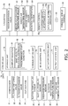
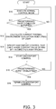
Fig. 3 >Fig. 3 is a control flowchart for an arousal control mode. - <
Fig. 4 >Fig. 4 is a block configuration diagram of an air conditioning apparatus according to modification A. - <
Fig. 5 >Fig. 5 is a control flowchart for an arousal control mode according to modification A. - <
Fig. 6 >Fig. 6 is a control flowchart for an arousal control mode according to modification B. - <
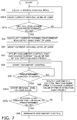
Fig. 7 >Fig. 7 is a control flowchart for an arousal control mode according to modification C. - <
Fig. 8 >Fig. 8 is a control flowchart for an arousal control mode according to modification D. - <
Fig. 9 >Fig. 9 is a graph illustrating a temporal change in the arousal level of the subject. - Hereinafter, an air conditioning control device according to an embodiment and an air conditioning apparatus provided with the air conditioning control device will be described with reference to the drawings. It should be noted that the following embodiment is a specific example of the present disclosure and is not intended to limit the technical scope of the content of the present disclosure, but can be modified, as appropriate, without departing from the spirit of the present disclosure.
-
Fig. 1 is a schematic configuration diagram of anair conditioning apparatus 100. Theair conditioning apparatus 100 is an apparatus that performs air conditioning of a target space by performing a vapor compression refrigeration cycle. - The
air conditioning apparatus 100 mainly includes anoutdoor unit 2, anindoor unit 50, a liquid-refrigerant connection pipe 6 and a gas-refrigerant connection pipe 7 that connect theoutdoor unit 2 and theindoor unit 50 to each other, an plurality ofremote controls 50a, each of which serves as an input device and an output device, and acontroller 70 that controls the operation of theair conditioning apparatus 100. - In the
air conditioning apparatus 100, a refrigeration cycle is performed such that refrigerant sealed in arefrigerant circuit 10 is compressed, cooled or condensed, decompressed, heated or evaporated, and then compressed again. - The
outdoor unit 2 is connected to theindoor unit 50 through the liquid-refrigerant connection pipe 6 and the gas-refrigerant connection pipe 7 and forms a portion of therefrigerant circuit 10. Theoutdoor unit 2 mainly includes acompressor 21, a four-way switching valve 22, anoutdoor heat exchanger 23, anoutdoor expansion valve 24, anoutdoor fan 25, a liquid-side shutoff valve 29, and a gas-side shutoff valve 30. - The
outdoor unit 2 further includes pipes constituting therefrigerant circuit 10, namely, adischarge pipe 31, asuction pipe 34, an outdoor gas-side pipe 33, and an outdoor liquid-side pipe 32. Thedischarge pipe 31 connects the discharge side of thecompressor 21 and a first connection port of the four-way switching valve 22 to each other. Thesuction pipe 34 connects the suction side of thecompressor 21 and a second connection port of the four-way switching valve 22 to each other. The outdoor gas-side pipe 33 connects a third connection port of the four-way switching valve 22 and the gas-side shutoff valve 30 to each other. The outdoor liquid-side pipe 32 extends from a fourth conection port of the four-way switching valve 22 to the liquid-side shutoff valve 29 through theoutdoor heat exchanger 23 and theoutdoor expansion valve 24. - The
compressor 21 is a device that compresses low-pressure refrigerant in the refrigeration cycle to high-pressure refrigerant. Thecompressor 21 is implemented here as a hermetically sealed compressor in which a positive displacement compression element (not illustrated), such as a rotary or a scroll compression element, is driven to rotate by a compressor motor M21. The compressor motor M21 is used to change volume and has an operating frequency that can be controlled by an inverter. - The connection state of the four-
way switching valve 22 can be switched to switch the four-way switching valve 22 between a cooling-operation connection state in which the suction side of thecompressor 21 and the gas-side shutoff valve 30 are connected to each other while the discharge side of thecompressor 21 and theoutdoor heat exchanger 23 are connected to each other and a heating-operation connection state in which the suction side of thecompressor 21 and theoutdoor heat exchanger 23 are connected to each other while the discharge side of thecompressor 21 and the gas-side shutoff valve 30 are connected to each other. - The
outdoor heat exchanger 23 is a heat exchanger that functions as a radiator for high-pressure refrigerant in the refrigeration cycle during a cooling operation and that functions as an evaporator for low-pressure refrigerant in the refrigeration cycle during a heating operation. - The
outdoor fan 25 generates an air flow for sucking outdoor air into theoutdoor unit 2, allowing the air to exchange heat with the refrigerant in theoutdoor heat exchanger 23, and then discharging the air to the outside. Theoutdoor fan 25 is driven to rotate by an outdoor fan motor M25. - The
outdoor expansion valve 24 is an electric expansion valve whose valve opening degree is controllable, and is disposed midway in the outdoor liquid-side pipe 32 between theoutdoor heat exchanger 23 and the liquid-side shutoff valve 29. - The liquid-
side shutoff valve 29 is a manual valve arranged in a connecting portion between the outdoor liquid-side pipe 32 and the liquid-refrigerant connection pipe 6. - The gas-
side shutoff valve 30 is a manual valve arranged in a connecting portion between the outdoor gas-side pipe 33 and the gas-refrigerant connection pipe 7. - The
outdoor unit 2 has various sensors arranged therein. Specifically, theoutdoor unit 2 has arranged therein, near thecompressor 21, asuction temperature sensor 35 that detects the temperature of refrigerant on the suction side of thecompressor 21, asuction pressure sensor 36 that detects a suction pressure, which is the pressure of refrigerant on the suction side of thecompressor 21, and adischarge pressure sensor 37 that detects a discharge pressure, which is the pressure of refrigerant on the discharge side of thecompressor 21. Theoutdoor heat exchanger 23 is also provided with an outdoor heat-exchange temperature sensor 38 that detects the temperature of refrigerant flowing through theoutdoor heat exchanger 23. Further, an outsideair temperature sensor 39 that detects the temperature of outdoor air sucked into theoutdoor unit 2 is arranged near theoutdoor heat exchanger 23 or theoutdoor fan 25. - The
outdoor unit 2 includes an outdoorunit control unit 20 that controls the operation of the components of theoutdoor unit 2. The outdoorunit control unit 20 has a microcomputer including a CPU, a memory, and the like. The outdoorunit control unit 20 is connected to an indoorunit control unit 57 of eachindoor unit 50 via a communication line, and transmits and receives control signals and the like. Further, the outdoorunit control unit 20 is electrically connected to thesuction temperature sensor 35, thesuction pressure sensor 36, thedischarge pressure sensor 37, the outdoor heat-exchange temperature sensor 38, and the outsideair temperature sensor 39, and receives a signal from each sensor. - The
indoor unit 50 is mounted on the wall surface, the ceiling, or the like of a room that is the target space. Theindoor unit 50 is connected to theoutdoor unit 2 through the liquid-refrigerant connection pipe 6 and the gas-refrigerant connection pipe 7 and forms a portion of therefrigerant circuit 10. - The
indoor unit 50 includes anindoor expansion valve 54, anindoor heat exchanger 52, and anindoor fan 53. - The
indoor unit 50 further includes an indoorliquid refrigerant pipe 58 that connects the liquid-side end of theindoor heat exchanger 52 and the liquid-refrigerant connection pipe 6 to each other, and an indoorgas refrigerant pipe 59 that connects the gas-side end of theindoor heat exchanger 52 and the gas-refrigerant connection pipe 7 to each other. - The
indoor expansion valve 54 is an electric expansion valve whose valve opening degree is controllable, and is disposed midway in the indoor liquidrefrigerant pipe 58. - The
indoor heat exchanger 52 is a heat exchanger that functions as an evaporator for low-pressure refrigerant in the refrigeration cycle during a cooling operation and that functions as a radiator for high-pressure refrigerant in the refrigeration cycle during a heating operation. - The
indoor fan 53 generates an air flow for sucking indoor air into theindoor unit 50, allowing the air to exchange heat with the refrigerant in theindoor heat exchanger 52, and then discharging the air to the outside. Theindoor fan 53 is driven to rotate by an indoor fan motor M53. - The
indoor unit 50 has various sensors arranged therein. Specifically, theindoor unit 50 has arranged therein an indoor heat-exchange temperature sensor 81 that detects the temperature of refrigerant flowing through theindoor heat exchanger 52, an indoorair temperature sensor 82 that detects the air temperature in a space where theindoor unit 50 is installed, anindoor humidity sensor 83 that detects the humidity of air in the space where theindoor unit 50 is installed, and aradiation temperature sensor 84 that contactlessly detects the radiation temperature at the position of a user in the space where theindoor unit 50 is installed. - The
indoor unit 50 further includes the indoorunit control unit 57 that controls the operation of the components of theindoor unit 50. The indoorunit control unit 57 has a microcomputer including a CPU, a memory, and the like. The indoorunit control unit 57 is connected to the outdoorunit control unit 20 via a communication line, and transmits and receives control signals and the like. - The indoor
unit control unit 57 is electrically connected to the indoor heat-exchange temperature sensor 81, the indoorair temperature sensor 82, theindoor humidity sensor 83, and theradiation temperature sensor 84, and receives a signal from each sensor. - The
remote control 50a is an input device used by the user of theindoor unit 50 to input various instructions to switch the operating state of theair conditioning apparatus 100. Theremote control 50a also functions as an output device for notifying the user of the operating state of theair conditioning apparatus 100 or providing a predetermined notification. Theremote control 50a and the indoorunit control unit 57 are connected to each other via a communication line and transmit and receive signals to and from each other. - Further, the
remote control 50a is provided with a clothingamount acceptance unit 51a that accepts information on the amount of clothing that the user wears, and a metabolicinformation grasping unit 51b for grasping the metabolic rate of the user. The clothingamount acceptance unit 51a accepts information on the amount of clothing that the user wears from the user via an input unit such as an operation button or a touch panel (not illustrated) provided in theremote control 50a. The amount of clothing is not limited and may be grasped by, for example, accepting selection of a clothing pattern determined by the user to be closest to their own clothing pattern among a plurality of types of clothing patterns for which the respective amounts of clothing are determined in advance. The metabolicinformation grasping unit 51b grasps a position information history of a personal mobile terminal 56 such as a mobile phone possessed by the user by using a GPS system or the like via a communication network such as theInternet 55 to grasp the metabolic rate of the user from the distance traveled in the most recent predetermined unit time (for example, the most recent 10 minutes) in accordance with a predetermined relational expression. - In the
air conditioning apparatus 100, the outdoorunit control unit 20 and the indoorunit control unit 57, which are connected to each other via a communication line, form thecontroller 70 serving as an air conditioning control device that controls the operation of theair conditioning apparatus 100. -
Fig. 2 is a block diagram schematically illustrating the general configuration of thecontroller 70 and components connected to thecontroller 70. - The
controller 70 has a plurality of control modes and controls the operation of theair conditioning apparatus 100 in accordance with the control mode. For example, thecontroller 70 has, as control modes, a normal operation mode that is executed in normal conditions, and an arousal control mode for increasing the arousal level of the user. - The
controller 70 is electrically connected to the actuators included in the outdoor unit 2 (specifically, the compressor 21 (the compressor motor M21), theoutdoor expansion valve 24, and the outdoor fan 25 (the outdoor fan motor M25)), and the various sensors included in the outdoor unit 2 (such as thesuction temperature sensor 35, thesuction pressure sensor 36, thedischarge pressure sensor 37, the outdoor heat-exchange temperature sensor 38, and the outside air temperature sensor 39). Thecontroller 70 is also electrically connected to the actuators included in the indoor unit 50 (specifically, the indoor fan 53 (the indoor fan motor M53) and the indoor expansion valve 54). Thecontroller 70 is also electrically connected to the indoor heat-exchange temperature sensor 81, the indoorair temperature sensor 82, theindoor humidity sensor 83, theradiation temperature sensor 84, and theremote control 50a. - The
controller 70 mainly includes astorage unit 71, acommunication unit 72, amode control unit 73, anactuator control unit 74, and anoutput control unit 75. These components of thecontroller 70 are implemented by the integrated functioning of the components included in the outdoorunit control unit 20 and/or the indoorunit control unit 57. - The
storage unit 71 is constituted by, for example, a ROM, a RAM, a flash memory, and the like and includes a volatile storage area and a non-volatile storage area. Thestorage unit 71 stores a control program that defines processes performed by the components of thecontroller 70. Thestorage unit 71 further stores predetermined information (for example, a value detected by each sensor, a command input to theremote control 50a, etc.) in a predetermined storage area, as appropriate, by using the components of thecontroller 70. - More specifically, the
storage unit 71 stores data of apredetermined comfort equation 91, data of a predetermined wind velocityrelational expression 92, data of apredetermined start condition 93, and the like. - Specifically, the data of the
comfort equation 91 represents an equation for calculating the value of the thermal environment evaluation index PMV of the user from the values of six elements, namely, the indoor air temperature, the radiation temperature at a location near the user, the relative humidity in the room, the wind velocity at the location near the user, the amount of clothing that the user wears, and the metabolic rate of the user, and is determined in advance. The thermal environment evaluation index PMV is not limited and may be a numerical value based on a seven-grade assessment scale according to ISO 7730 (1994) or ISO 7730 (2005). - The data of the wind velocity
relational expression 92 represents a relational expression for calculating the wind velocity at a location near the position of the user in the room and corresponding to the driving state of theindoor fan 53, and the value of the wind velocity is obtained by specifying an input value to the indoor fan motor M53 of theindoor fan 53. - The data of the
predetermined start condition 93 is data indicating a condition for starting the arousal control mode from a state in which theair conditioning apparatus 100 is executing the normal control mode for the cooling operation, the dehumidifying operation, the heating operation, or the like. The data of thepredetermined start condition 93 is not limited and may be, for example, a condition that a specific time period is reached or a condition that a predetermined time interval has elapsed since the last time the arousal control mode was terminated. - The
communication unit 72 is a functional unit serving as a communication interface for transmitting and receiving signals to and from devices connected to thecontroller 70. Thecommunication unit 72 transmits a predetermined signal to a designated actuator in response to receipt of a request from theactuator control unit 74. Further, thecommunication unit 72 receives signals output from thesensors 35 to 39 and 81 to 84 and theremote control 50a and stores the signals in a predetermined storage area of thestorage unit 71. - The
mode control unit 73 is a functional unit that performs processing such as switching between the control modes. If thepredetermined start condition 93 is not satisfied for anyindoor unit 50, themode control unit 73 sets the control mode to the normal operation mode. - On the other hand, if the
predetermined start condition 93 is satisfied for any one of theindoor unit 50, themode control unit 73 switches the control mode to the arousal control mode. - The
actuator control unit 74 controls the operation of the actuators (such as the compressor 21) included in theair conditioning apparatus 100 along with the control program in accordance with the situation. - For example, in the normal operation mode, the
actuator control unit 74 controls the number of revolutions of thecompressor 21, the numbers of revolutions of theoutdoor fan 25 and theindoor fan 53, the valve opening degree of theoutdoor expansion valve 24, the valve opening degree of theindoor expansion valve 54, and the like in real time in accordance with a set temperature, values detected by various sensors, and the like. - In the arousal control mode, the
actuator control unit 74 controls the operation of the actuators so that a predetermined operation can be performed. Specifically, theactuator control unit 74 controls the number of revolutions of thecompressor 21, the numbers of revolutions of theoutdoor fan 25 and theindoor fan 53, the valve opening degree of theoutdoor expansion valve 24, the valve opening degree of theindoor expansion valve 54, and the like in real time so that the PMV (thermal environment evaluation index) of the user becomes worse than the current value. - The
output control unit 75 is a functional unit that controls the operation of theremote control 50a serving as a display device. - The
output control unit 75 causes theremote control 50a to output predetermined information so that information related to the operating state or conditions can be presented to the administrator. - For example, during the execution of the normal operation mode, the
output control unit 75 causes theremote control 50a to display various information such as a set temperature. - During the execution of the arousal control mode, the
output control unit 75 causes a display of theremote control 50a to display information indicating that the arousal control mode is ongoing. - The following describes the normal operation mode.
- The normal operation mode includes a cooling operation mode, a dehumidifying operation mode, and a heating operation mode.
- The
controller 70 determines and executes the cooling operation mode, the dehumidifying operation mode, or the heating operation mode in accordance with an instruction accepted from theremote control 50a or the like. - In the
air conditioning apparatus 100, in the cooling operation mode, the connection state of the four-way switching valve 22 is set to the cooling-operation connection state in which the suction side of thecompressor 21 and the gas-side shutoff valve 30 are connected to each other while the discharge side of thecompressor 21 and theoutdoor heat exchanger 23 are connected to each other. The refrigerant with which therefrigerant circuit 10 is filled is mainly circulated through thecompressor 21, theoutdoor heat exchanger 23, theoutdoor expansion valve 24, theindoor expansion valve 54, and theindoor heat exchanger 52 in this order. - More specifically, when the cooling operation mode is started, in the
refrigerant circuit 10, the refrigerant is sucked into thecompressor 21, compressed, and then discharged. A low pressure in the refrigeration cycle corresponds to a suction pressure detected by thesuction pressure sensor 36, and a high pressure in the refrigeration cycle corresponds to a discharge pressure detected by thedischarge pressure sensor 37. - In the
compressor 21, capacity control is performed in accordance with the cooling load required for theindoor unit 50. Specifically, the target value of the suction pressure is set in accordance with the cooling load required for theindoor unit 50, and the operating frequency of thecompressor 21 is controlled so that the suction pressure becomes equal to the target value. - The gas refrigerant discharged from the
compressor 21 passes through thedischarge pipe 31 and the four-way switching valve 22 and flows into the gas-side end of theoutdoor heat exchanger 23. - The gas refrigerant that has flowed into the gas-side end of the
outdoor heat exchanger 23 releases heat and condenses into a liquid refrigerant in theoutdoor heat exchanger 23 by exchanging heat with outdoor-side air supplied by theoutdoor fan 25. The liquid refrigerant flows out of the liquid-side end of theoutdoor heat exchanger 23. - The liquid refrigerant that has flowed out of the liquid-side end of the
outdoor heat exchanger 23 passes through the outdoor liquid-side pipe 32, theoutdoor expansion valve 24, the liquid-side shutoff valve 29, and the liquid-refrigerant connection pipe 6 and flows into theindoor unit 50. In the cooling operation mode, theoutdoor expansion valve 24 is controlled to be fully open. - The refrigerant that has flowed into the
indoor unit 50 passes through a portion of the indoor liquidrefrigerant pipe 58 and flows into theindoor expansion valve 54. The refrigerant that has flowed into theindoor expansion valve 54 is decompressed by theindoor expansion valve 54 until the refrigerant becomes low-pressure refrigerant in the refrigeration cycle, and then flows into the liquid-side end of theindoor heat exchanger 52. In the cooling operation mode, the valve opening degree of theindoor expansion valve 54 is controlled such that the degree of superheating of refrigerant to be sucked into thecompressor 21 becomes equal to a predetermined degree of superheating. The degree of superheating of refrigerant to be sucked into thecompressor 21 is calculated by thecontroller 70 by using the temperature detected by thesuction temperature sensor 35 and the pressure detected by thesuction pressure sensor 36. The refrigerant that has flowed into the liquid-side end of theindoor heat exchanger 52 evaporates into a gas refrigerant in theindoor heat exchanger 52 by exchanging heat with indoor air supplied by theindoor fan 53. The gas refrigerant flows out of the gas-side end of theindoor heat exchanger 52. The gas refrigerant that has flowed out of the gas-side end of theindoor heat exchanger 52 flows to the gas-refrigerant connection pipe 7 through the indoorgas refrigerant pipe 59. - In this way, the refrigerant flowing through the gas-refrigerant connection pipe 7 passes through the gas-
side shutoff valve 30, the outdoor gas-side pipe 33, the four-way switching valve 22, and thesuction pipe 34 and is again sucked into thecompressor 21. - The dehumidifying operation mode is the same as the cooling operation mode described above, except that the operation of the
indoor fan 53 is stopped to limit the supply of indoor air to theindoor heat exchanger 52. - In the
air conditioning apparatus 100, in the heating operation mode, the connection state of the four-way switching valve 22 is set to the heating-operation connection state in which the suction side of thecompressor 21 and theoutdoor heat exchanger 23 are connected to each other while the discharge side of thecompressor 21 and the gas-side shutoff valve 30 are connected to each other. The refrigerant with which therefrigerant circuit 10 is filled is mainly circulated through thecompressor 21, theindoor heat exchanger 52, theindoor expansion valve 54, theoutdoor expansion valve 24, and theoutdoor heat exchanger 23 in this order. - More specifically, when the heating operation mode is started, in the
refrigerant circuit 10, the refrigerant is sucked into thecompressor 21, compressed, and then discharged. A low pressure in the refrigeration cycle corresponds to a suction pressure detected by thesuction pressure sensor 36, and a high pressure in the refrigeration cycle corresponds to a discharge pressure detected by thedischarge pressure sensor 37. - In the
compressor 21, capacity control is performed in accordance with the heating load required for theindoor unit 50. Specifically, a target value of the discharge pressure is set in accordance with the heating load required for theindoor unit 50, and the operating frequency of thecompressor 21 is controlled such that the discharge pressure becomes equal to the target value. - The gas refrigerant discharged from the
compressor 21 flows through thedischarge pipe 31, the four-way switching valve 22, the outdoor gas-side pipe 33, and the gas-refrigerant connection pipe 7, and then flows into theindoor unit 50 through the indoorgas refrigerant pipe 59. - The refrigerant that has flowed into the
indoor unit 50 passes through the indoorgas refrigerant pipe 59 and flows into the gas-side end of theindoor heat exchanger 52. The refrigerant that has flowed into the gas-side end of theindoor heat exchanger 52 releases heat and condenses into a liquid refrigerant in theindoor heat exchanger 52 by exchanging heat with indoor air supplied by theindoor fan 53. The liquid refrigerant flows out of the liquid-side end of theindoor heat exchanger 52. The refrigerant that has flowed out of the liquid-side end of theindoor heat exchanger 52 flows to the liquid-refrigerant connection pipe 6 through the indoor liquidrefrigerant pipe 58 and theindoor expansion valve 54. In the heating operation mode, the valve opening degree of theindoor expansion valve 54 is controlled to be fully open. - In this way, the refrigerant flowing through the liquid-
refrigerant connection pipe 6 flows into theoutdoor expansion valve 24 through the liquid-side shutoff valve 29 and the outdoor liquid-side pipe 32. - The refrigerant that has flowed into the
outdoor expansion valve 24 is decompressed until the refrigerant becomes low-pressure refrigerant in the refrigeration cycle, and then flows into the liquid-side end of theoutdoor heat exchanger 23. In the heating operation mode, the valve opening degree of theoutdoor expansion valve 24 is controlled such that the degree of superheating of refrigerant to be sucked into thecompressor 21 becomes equal to a predetermined degree of superheating. - The refrigerant that has flowed into the liquid-side end of the
outdoor heat exchanger 23 evaporates into a gas refrigerant in theoutdoor heat exchanger 23 by exchanging heat with outdoor air supplied by theoutdoor fan 25. The gas refrigerant flows out of the gas-side end of theoutdoor heat exchanger 23. - The refrigerant that has flowed out of the gas-side end of the
outdoor heat exchanger 23 passes through the four-way switching valve 22 and thesuction pipe 34 and is again sucked into thecompressor 21. - The following describes a processing flow in a case where the normal control mode is followed by the arousal control mode with reference to a flowchart illustrated in
Fig. 3 . Here, the processing flow from a state in which the normal control mode is executed will be exemplified. - A user present in the room is assumed to have completed the input of data of the amount of clothing that the user wears via the clothing
amount acceptance unit 51a of theremote control 50a in advance, and theremote control 50a is assumed to know the amount of clothing that the user wears. It is also assumed that the user always holds a personal mobile terminal such as a mobile phone in a state in which the location position is identified through the GPS. - In step S10, the
mode control unit 73 and theactuator control unit 74 execute the normal control mode. Specifically, themode control unit 73 switches to the operation selected by the user via theremote control 50a among the cooling operation, the dehumidifying operation, and the heating operation, and theactuator control unit 74 controls the actuators such as thecompressor 21 so that a set temperature set by the user can be implemented. - In step S11, the
mode control unit 73 determines whether a predetermined start condition for starting the arousal control mode is satisfied. The predetermined start condition is not limited and may be, for example, a predetermined time of each day (such as about 13:30 around which people are likely to be in low-arousal-level state after lunch) or a time at which a predetermined time interval or more has elapsed since the last time discomfort control was terminated. If the predetermined start condition is satisfied, the process proceeds to step S12. If the predetermined start condition is not satisfied, step S10 is repeated. - In step S12, the
mode control unit 73 calculates the current thermal environment evaluation index (PMV) of the user. Specifically, themode control unit 73 reads thecomfort equation 91 stored in thestorage unit 71 and substitutes the values of six elements, namely, the indoor air temperature (value sensed by the indoor air temperature sensor 82), the radiation temperature at a location near the user (value sensed by the radiation temperature sensor 84), the relative humidity in the room (value sensed by the indoor humidity sensor 83), the wind velocity at the location near the user, the amount of clothing that the user wears (the amount of clothing accepted by the clothingamount acceptance unit 51a and thus grasped by theremote control 50a), and the metabolic rate of the user, into thecomfort equation 91 to calculate the value of the thermal environment evaluation index (PMV) of the user. - The wind velocity at the location near the position of the user is calculated by the
mode control unit 73 substituting the current control air flow rate of theindoor fan 53 into the wind velocityrelational expression 92 stored in thestorage unit 71. Since the metabolicinformation grasping unit 51b calculates the metabolic rate of the user from the distance traveled in the most recent predetermined unit time (for example, the most recent 10 minutes) in accordance with a predetermined relational expression, themode control unit 73 reads the value of the metabolic rate of the user. - In the way described above, the
mode control unit 73 substitutes the grasped values of the six elements into thecomfort equation 91 to calculate the current value of the thermal environment evaluation index (PMV) of the user. - In step S13, the
mode control unit 73 specifies a set temperature and/or set air flow rate for arousal that can change the thermal environment evaluation index (PMV) identified in step S12 by 1 in the direction away from 0. For example, themode control unit 73 specifies, using thecomfort equation 91, discomfort control having a new set temperature or set air flow rate that can change the thermal environment evaluation index (PMV) by 1 in the direction of discomfort by changing the set temperature in the room or the set air flow rate of theindoor fan 53 so as to make the user feel uncomfortable without changing the indoor humidity of theair conditioning apparatus 100. - In step S14, the
actuator control unit 74 starts the discomfort control specified in step S13, and controls the actuators such as thecompressor 21 so that the set temperature and the set humidity, which are newly set, can be implemented. - In step S15, the
mode control unit 73 determines whether a predetermined duration has elapsed since the start of the discomfort control in step S14. The predetermined duration is not limited and is preferably 1 minute or more in view of making the user feel uncomfortable, preferably 2 minutes or more in view of sufficiently giving a discomfort feeling, and preferably 4 minutes or more in view of more reliably providing discomfort. It is preferable that the duration of the discomfort control not exceed 30 minutes in view of making the user less sensitive to a stimulus caused by an environment change and in view of the reduction of the effect of leading to arousal. If the predetermined duration has elapsed, the process proceeds to step S16. If the predetermined duration has not elapsed, the discomfort control is continuously performed until the predetermined duration has elapsed. - In step S16, the
mode control unit 73 terminates the discomfort control. Then, the process returns to step S10, and the normal control is resumed to repeatedly perform the processing described above. - The
air conditioning apparatus 100 including thecontroller 70 according to this embodiment is subjected to discomfort control, separately from the normal control mode, so that the user can feel more uncomfortable than they currently do. The discomfort control causes a change in environment so that the value of the thermal environment evaluation index (PMV) of the user can be changed in a direction such that the user feels more uncomfortable than they currently do. Accordingly, for example, it may be possible to arouse a sleepy user. In this way, it is possible to increase the arousal level of the user by using a novel method of making the value of the thermal environment evaluation index (PMV) worse than the current value. - In this embodiment, the thermal environment evaluation index (PMV) is used as the index of discomfort control. Performing discomfort control that can worsen the value of the PMV of the user makes it possible to more reliably provide discomfort to the user and arouse the user.
- In this embodiment, when the discomfort control is performed, the operation is performed such that the value of the PMV of the user is changed by 1 or more so as to provide discomfort. This makes it possible to more sufficiently provide discomfort to the user and arouse the user.
- In this embodiment, the discomfort control is continuously performed for a predetermined duration or longer. This makes it possible to more reliably change the environment in the room where the user is present, provide discomfort to the user, and arouse the user.
- In this embodiment, normal operation is performed to make the user comfortable, and discomfort control is performed only when a predetermined start condition is satisfied, thereby making it possible to arouse the user only under a specific condition.
- In the embodiment described above, an example of embodiments of the present disclosure has been described; the embodiment described above is not intended to limit the content of the present disclosure in any way, and the present disclosure is not limited to the embodiment described above. The content of the present disclosure may be modified as appropriate without departing from the spirit of the present disclosure, and it is to be understood that such modifications also fall within the present disclosure.
- In addition, the embodiment described above and a plurality of modifications described below may be combined as appropriate so as to maintain consistency between them.
- In the embodiment described above, the process of performing discomfort control for making the user uncomfortable so that the arousal level of the user can be increased has been exemplified and described.
- Alternatively, for example, as illustrated in
Fig. 4 , the discomfort control may be sufficiently performed until it is confirmed that the arousal level of the user is actually improved. - Specifically, the
controller 70 according to this modification is communicably connected to abiometric sensor 40, and thestorage unit 71 stores arousallevel comparison data 94. - The
biometric sensor 40 is a sensor for grasping the arousal level of the user and can be implemented using, for example, anelectrocardiogram waveform sensor 41 that detects an electrocardiogram waveform of the user, and afacial expression camera 42 that detects the facial expression of the user. Theelectrocardiogram waveform sensor 41 is used by being attached to near the heart of the user and is capable of wirelessly transmitting detected electrocardiogram waveform data to thecontroller 70. Thefacial expression camera 42 is disposed at a specific position in a room where an image of the facial expression of the user can be captured, and is capable of wirelessly transmitting detected facial expression data to thecontroller 70. - The arousal
level comparison data 94 stored in thestorage unit 71 is data for estimating the arousal level of the user from the respective items of detection content of theelectrocardiogram waveform sensor 41 and thefacial expression camera 42, which serve as thebiometric sensor 40, on the basis of the known relationship between the electrocardiogram waveform and the arousal level and the known relationship between the arousal level and the facial expression corresponding to a difference between a facial expression of the user and a predetermined reference facial expression. For example, the arousal level corresponding to the electrocardiogram waveform, which is grasped from theelectrocardiogram waveform sensor 41, may be identified by referring to relationship data stored in advance between the electrocardiogram waveform and the arousal level and, in addition, corrected by a predetermined amount of arousal level correction corresponding to a difference between the facial expression grasped from thefacial expression camera 42 and the predetermined reference facial expression to grasp the arousal level of the user. - When the configuration described above is used, for example, as illustrated in a flowchart in
Fig. 5 , the normal control mode may be followed by the arousal control mode. - As in the embodiment described above, a user present in the room is assumed to have completed the input of data of the amount of clothing that the user wears via the clothing
amount acceptance unit 51a of theremote control 50a in advance, and theremote control 50a is assumed to know the amount of clothing that the user wears. It is also assumed that the user always holds a personal mobile terminal such as a mobile phone in a state in which the location position is identified through the GPS. - In step S20, as in the embodiment described above, the
mode control unit 73 and theactuator control unit 74 execute the normal control mode. - In step S21, as in the embodiment described above, the
mode control unit 73 determines whether a predetermined start condition for starting the arousal control mode is satisfied. If the predetermined start condition is satisfied, the process proceeds to step S22. If the predetermined start condition is not satisfied, step S20 is repeated. - In step S22, as in the embodiment described above, the
mode control unit 73 calculates the current thermal environment evaluation index (PMV) of the user. - In step S23, the
mode control unit 73 calculates the current estimated value of the arousal level of the user. Specifically, the current estimated value of the arousal level of the user is grasped from the respective detection results of theelectrocardiogram waveform sensor 41 and thefacial expression camera 42 in thebiometric sensor 40 and the arousallevel comparison data 94 stored in thestorage unit 71. - In step S24, the
mode control unit 73 specifies a discomfort control having a set temperature and/or a set air flow rate for arousal that can change the thermal environment evaluation index (PMV) identified in step S12 by 1 in the direction away from 0. - In step S25, the
actuator control unit 74 starts the specified discomfort control and controls the actuators such as thecompressor 21 so that the set temperature and the set humidity, which are newly set, can be implemented. - In step S26, the
mode control unit 73 determines whether a predetermined duration has elapsed since the start of the discomfort control in step S25. If the predetermined duration has elapsed, the process proceeds to step S27. If the predetermined duration has not elapsed, the discomfort control is continuously performed until the predetermined duration has elapsed. - In step S27, the
mode control unit 73 again grasps the estimated value of the arousal level of the user at this point in time, and determines whether the estimated value has increased by a predetermined value or more from the estimated value of the arousal level of the user grasped in step S23. If the estimated value has increased by the predetermined value or more, the process proceeds to step S29. If the estimated value has not increased by the predetermined value or more, the process proceeds to step S28. - In step S28, the
mode control unit 73 specifies discomfort control that can more greatly change the value of the PMV of the user in the direction away from 0 than the most recently performed discomfort control, and then the process proceeds to step S25. In this way, repeating steps S25, S26, S27, and S28 makes it possible to reliably increase the estimated value of the arousal level of the user (i.e., the processing described above is repeatedly performed until it is determined in step S27 that the estimated value of the arousal level of the user has increased by the predetermined value or more). - In step S29, the
mode control unit 73 terminates the discomfort control. Then, the process returns to step S20, and the normal control is resumed to repeatedly perform the processing described above. - According to the process described above, the discomfort control makes it possible to more reliably improve the arousal level of the user.
- In the embodiment described above, a predetermined start condition for starting the discomfort control has been exemplified and described in which a predetermined time is reached or a predetermined time interval or more has elapsed since the last time discomfort control was terminated.
- The predetermined start condition for starting the discomfort control is not limited to this. For example, as illustrated in
Fig. 6 , the processing of step S11 in the embodiment described above may be changed to processing (step S11a) of determining whether the arousal level of the subject has a value lower than a predetermined value during the execution of the normal control mode. In this case, step S11 a described above is performed after the current arousal level of the user is grasped (step S10.5) while the normal control mode is executed. If the arousal level of the subject becomes lower than the predetermined value, the process may proceed to step S12, and the discomfort control may be performed without any change. - Alternatively, in place of the condition that the arousal level of the subject becomes lower than the predetermined value, a condition that the decrease in the arousal level of the subject per unit time is larger than a predetermined value may be used as the condition for proceeding to step S12.
- The control described above makes it possible to perform discomfort control only when the arousal level of the subject decreases while the normal control mode is executed. Accordingly, it is possible to prevent the discomfort control from being performed even though the subject is in a sufficiently aroused state.
- Also in modification A described above, as in the embodiment described above, a predetermined start condition for starting the discomfort control has been exemplified and described in which a predetermined time of day is reached or a predetermined time interval or more has elapsed since the last time discomfort control was terminated.
- Also in the processing according to modification A, the predetermined start condition for starting the discomfort control is not limited to this. For example, as illustrated in
Fig. 7 , the processing of step S21 according to modification A described above may be changed to processing (step S21a) of determining whether the arousal level of the subject has a value lower than a predetermined value during the execution of the normal control mode. In this case, step S21a described above is performed after the current arousal level of the user is grasped (step S20.5) while the normal control mode is executed. If the arousal level of the subject becomes lower than the predetermined value, the process may proceed to step S22, and the discomfort control may be performed without any change. In addition, the current value of the arousal level of the user, which has been changed by the discomfort control performed in step S25, may be again grasped (step S26.5), it may be checked whether the changed arousal level of the user is greater than or equal to a predetermined value (step S27a), and the discomfort control may be terminated. - Alternatively, in place of the condition that the arousal level of the subject becomes lower than the predetermined value, a condition that the decrease in the arousal level of the subject per unit time is larger than a predetermined value may be used as the condition for proceeding to step S22.
- The control described above makes it possible to perform discomfort control only when the arousal level of the subject decreases while the normal control mode is executed. Accordingly, it is possible to prevent the discomfort control from being performed even though the subject is in a sufficiently aroused state.
- In the embodiment described above, discomfort control performed by grasping the current value of the PMV of the user and determining the target control value of the
air conditioning apparatus 100 so that the value of the PMV becomes equal to a value expected to make the user feel more uncomfortable has been exemplified and described. - Alternatively, for example, as illustrated in
Fig. 8 , the temperature of the room where the user is present may be grasped as a comfort-related value (step S12a), the set temperature of theair conditioning apparatus 100 may be determined so that the temperature of the room becomes equal to a value expected to make the user feel more uncomfortable to specify discomfort control (step S13a), and the specified discomfort control may be performed. The method for determining the set temperature for the discomfort control described above is not limited. For example, when the cooling operation is being performed in the normal control mode, the set temperature may be set to a temperature higher than the current temperature in the room by a predetermined temperature or more, and when the heating operation is being performed in the normal control mode, the set temperature may be set to a temperature lower than the current temperature in the room by a predetermined temperature or more. Alternatively, a discomfort temperature expected to make the user feel uncomfortable regardless of the type of the normal control mode may be stored in a memory in advance, and discomfort control may be specified so that the discomfort temperature is set as the target value. - The comfort-related value is not limited to the PMV or the temperature, and the humidity of the room where the user is present, the wind velocity of conditioned air delivered to the user from the
air conditioning apparatus 100, the radiation in the room where the user is present, the discomfort index of the user, or the like may be used as the comfort-related value. - In the embodiment described above, the case where discomfort control that can change the value of the PMV of the user in the direction away from 0 is specified has been exemplified and described.
- However, a case where the PMV of the user is changed to provide discomfort to the user is not limited to the case where the value of the PMV is changed in the direction away from 0. Alternatively, the value of the PMV may be changed across 0. In this case, the value of the PMV may be changed so that the absolute value of the PMV becomes larger than the current value while the value of the PMV is changed across 0.
- In the embodiment described above, a case has been exemplified and described in which discomfort control is specified and executed such that the target value is set to the set temperature and/or set air flow rate for arousal that can change the current thermal environment evaluation index (PMV) by 1 in the direction away from 0.
- Alternatively, the index used for the discomfort control is not limited to the thermal environment evaluation index (PMV). For example, the discomfort index of the subject may be used as the index, or the degree of deviation of the temperature of the target space from the set temperature may be used as the index.
- The discomfort index can be obtained by calculating 0.81 T + 0.01 H (0.99 T - 1.43) + 46.3, where T (°C) denotes the dry-bulb temperature (temperature of air) and H (%) denotes the relative humidity. When the discomfort control is performed using the discomfort index as the index, the current discomfort index may be obtained, and control may be performed such that the target value is set to a set temperature or set humidity that makes the discomfort index greater than the current value.
- When the discomfort control is performed using the degree of deviation of the temperature of the target space from the set temperature as the index, the current degree of deviation may be obtained, and control may be performed such that the target value is set to a set temperature that makes the deviation greater than the current value of the degree of deviation.
- The embodiment described above may be applied to a case where a plurality of users are present in a room, a personal air conditioning means is provided for each individual, and each personal air conditioning means is controlled to provide discomfort to a corresponding one of the users.
- A temporal change in the arousal level of the subject was measured when a specific initial thermal environment for a target space where the subject was present was changed to a thermal environment different from the initial thermal environment.
- In the initial thermal environment, the air temperature was 27.3°C, the wall surface temperature was 27.3°C, the relative humidity was 31.6%, the average wind velocity was 0.1 m/s, the amount of clothing was 0.3 clo (short-sleeve shirt and short pants), and the metabolic rate was 1.1 met. The calculated value of the thermal environment evaluation index (PMV) in the initial thermal environment was 0.13.
- In contrast, in the thermal environment changed from the initial thermal environment, the air temperature was 21.6°C, the wall surface temperature was 27.3°C, the relative humidity was 31.6%, the average wind velocity was 0.3 m/s, the amount of clothing was 0.3 clo (short-sleeve shirt and short pants), and the metabolic rate was 1.1 met. The calculated value of the thermal environment evaluation index (PMV) in this thermal environment was -2.02.
- The subject was a person who had been in the initial thermal environment for 30 minutes or longer in advance and therefore accustomed to the environment.
- The discomfort control for changing the thermal environment was performed aiming that the air temperature would reach 21.6°C, and it took 15 seconds for an air temperature of 27.3°C to reach an air temperature of 21.6°C (the air blow was directed toward the subject to rapidly decrease the temperature).
- Then, the temporal change in the arousal level of the subject was measured from the point in time at which the discomfort control was started.
- The arousal level of the subject was defined as the inverted value of the sleepiness evaluation value of the subject. That is, evaluation was made such that the larger the sleepiness evaluation value, the lower the arousal level, and the lower the sleepiness evaluation value, the higher the arousal level. Specifically, the arousal level was evaluated as 1 when the sleepiness evaluation value was 5, the arousal level was evaluated as 2 when the sleepiness evaluation value was 4, the arousal level was evaluated as 3 when the sleepiness evaluation value was 3, the arousal level was evaluated as 4 when the sleepiness evaluation value was 2, and the arousal level was evaluated as 5 when the sleepiness evaluation value was 1.
- The sleepiness evaluation value was obtained by performing evaluation in accordance with the following five-grade criteria by a trained evaluator observing the subject.
- 1: Not at all sleepy (Rapid and frequent eye movements. Blinking in stable cycles. Active movements along with body movements.)
- 2: Slightly sleepy (Slow eye movements. Lips open.)
- 3: Sleepy (Slow and frequent blinking. Mouth movements. Corrected sitting positions. Hands on face.)
- 4: Fairly sleepy (Blinking that seems to be conscious. Unnecessary body movements such as shaking the head and moving the shoulders up and down. Frequent yawning, and observed deep breathing. Slow blinking and slow eye movements.)
- 5 Very sleepy (Eyes closed. Head tilted downwards. Head rolled back.)
- A temporal change in the arousal level of the subject based on the above is illustrated in a graph in
Fig. 9 . - According to the results illustrated in
Fig. 9 , in the environment where the PMV was -2.02, compared to the environment where the PMV was 0.13, the increase in the arousal level of the subject for a duration of 1 minute was 0.28, the increase at the elapse of 2 minutes was 0.56, the increase at the elapse of 3 minutes was 0.61, and the increase at the elapse of 4 minutes was 1.06. After the elapse of 4 minutes, a decrease in the arousal level was observed. - While an embodiment of the present disclosure has been described, it will be understood that forms and details can be changed in various ways without departing from the spirit and scope of the present disclosure as recited in the claims.
-
- 40
- biometric sensor
- 41
- electrocardiogram waveform sensor
- 42
- facial expression camera
- 51a
- clothing amount acceptance unit (first information grasping unit)
- 51b
- metabolic information grasping unit (first information grasping unit)
- 70
- controller (air conditioning control device)
- 73
- mode control unit (control unit, second information grasping unit)
- 82
- indoor air temperature sensor (first information grasping unit)
- 83
- indoor humidity sensor (first information grasping unit)
- 84
- radiation temperature sensor (first information grasping unit)
- 91
- comfort equation (first information grasping unit)
- 92
- wind velocity relational expression (first information grasping unit)
- 100
- air conditioning apparatus (air conditioning means)
- PTL 1:
Japanese Unexamined Patent Application Publication No. H10-259943
Claims (12)
- An air conditioning control device (70) for controlling air conditioning means (100) capable of changing an air environment of a target space, the air conditioning control device comprising:a first information grasping unit (82, 83, 84, 51a, 51b, 92, 91) for grasping a predetermined comfort-related value relating to comfort of a subject; anda control unit (73) that controls the air conditioning means so as to satisfy a predetermined discomfort condition on the basis of the comfort-related value grasped by the first information grasping unit.
- The air conditioning control device according to claim 1, wherein
the comfort-related value is grasped from at least a temperature and a humidity in the target space. - The air conditioning control device according to claim 2, whereinthe comfort-related value is a PMV (thermal environment evaluation index), andthe control unit controls the air conditioning means to increase an absolute value of the PMV of the subject grasped by the first information grasping unit so that the absolute value of the PMV of the subject is larger than a current value.
- The air conditioning control device according to claim 3, wherein
the control unit controls the air conditioning means to increase the absolute value of the PMV of the subject grasped by the first information grasping unit so that the absolute value of the PMV of the subject is larger than the current value by 1 or more. - The air conditioning control device according to claim 4, wherein
the control unit controls the air conditioning means to continue control for 4 minutes or more, the control being control for increasing the absolute value of the PMV of the subject grasped by the first information grasping unit so that the absolute value of the PMV of the subject is larger than the current value by 2 or more. - The air conditioning control device according to any one of claims 1 to 4, wherein
the control unit continues control for at least 1 minute or more, the control being based on the comfort-related value grasped by the first information grasping unit. - The air conditioning control device according to any one of claims 1 to 6,
wherein
the control unit sets a duration of control to 30 minutes or less, the control being based on the comfort-related value grasped by the first information grasping unit. - The air conditioning control device according to any one of claims 1 to 7, wherein
the control unit is capable of executing normal control for controlling the air conditioning means so that a set temperature condition of the target space is satisfied, and
the control unit starts control in a case where a predetermined start condition is satisfied while the normal control is being executed, the control being based on the comfort-related value grasped by the first information grasping unit. - The air conditioning control device according to claim 8, wherein
the predetermined start condition is a condition regarding a predetermined time of day. - The air conditioning control device according to any one of claims 1 to 9, further comprising
a second information grasping unit (73) for grasping physical and mental state information or biological state information of the subject, wherein
the control unit controls the air conditioning means to perform control based on the comfort-related value grasped by the first information grasping unit to increase an arousal level of the subject grasped by the second information grasping unit. - The air conditioning control device according to claim 8, further comprising
a second information grasping unit (73) for grasping physical and mental state information or biological state information of the subject, wherein
the predetermined start condition is a condition that an arousal level of the subject grasped by the second information grasping unit is equal to or less than a predetermined value. - An air conditioning apparatus (100) comprising
the air conditioning control device (70) according to any one of claims 1 to 11.
Applications Claiming Priority (2)
| Application Number | Priority Date | Filing Date | Title |
|---|---|---|---|
| JP2018168638A JP6822453B2 (en) | 2018-09-10 | 2018-09-10 | Air conditioning controller and air conditioner |
| PCT/JP2019/034647 WO2020054519A1 (en) | 2018-09-10 | 2019-09-03 | Air conditioner control device and air conditioner apparatus |
Publications (3)
| Publication Number | Publication Date |
|---|---|
| EP3851756A1 true EP3851756A1 (en) | 2021-07-21 |
| EP3851756A4 EP3851756A4 (en) | 2022-05-18 |
| EP3851756B1 EP3851756B1 (en) | 2023-12-06 |
Family
ID=69777621
Family Applications (1)
| Application Number | Title | Priority Date | Filing Date |
|---|---|---|---|
| EP19860560.2A Active EP3851756B1 (en) | 2018-09-10 | 2019-09-03 | Air conditioner control device and air conditioner apparatus |
Country Status (8)
| Country | Link |
|---|---|
| US (1) | US11835247B2 (en) |
| EP (1) | EP3851756B1 (en) |
| JP (1) | JP6822453B2 (en) |
| CN (1) | CN112673215A (en) |
| AU (1) | AU2019337129B2 (en) |
| PH (1) | PH12021550440A1 (en) |
| SG (1) | SG11202102181XA (en) |
| WO (1) | WO2020054519A1 (en) |
Families Citing this family (7)
| Publication number | Priority date | Publication date | Assignee | Title |
|---|---|---|---|---|
| SG10202110025UA (en) * | 2017-09-28 | 2021-10-28 | Daikin Ind Ltd | Control device of environment control means |
| WO2020121425A1 (en) * | 2018-12-12 | 2020-06-18 | 三菱電機株式会社 | State determination device, state determination method, and state determination program |
| JP7522601B2 (en) * | 2020-07-30 | 2024-07-25 | ダイキン工業株式会社 | TEMPERATURE ESTIMATION DEVICE, AIR CONDITIONER, AND TEMPERATURE CALCULATION METHOD |
| CN120615156A (en) * | 2023-01-31 | 2025-09-09 | 大金工业株式会社 | Environmental control device |
| CN116255723B (en) * | 2023-03-30 | 2025-11-04 | 广东开利暖通空调股份有限公司 | Control methods, devices, computer equipment, and storage media for air conditioning preheating function |
| CN117053378A (en) * | 2023-05-18 | 2023-11-14 | 苏州科技大学 | An intelligent control method for HVAC based on user portraits |
| CN120557786B (en) * | 2025-07-30 | 2025-09-19 | 南京深度智控科技有限公司 | A deep learning-based air-cooling air conditioning control method and system |
Family Cites Families (20)
| Publication number | Priority date | Publication date | Assignee | Title |
|---|---|---|---|---|
| KR0133482B1 (en) * | 1994-03-09 | 1998-05-15 | 구자홍 | Pmv calculating method |
| JP3589495B2 (en) * | 1995-02-17 | 2004-11-17 | 松下電器産業株式会社 | Psychological evaluation method according to living conditions and living environment control method according to living conditions |
| US5762265A (en) * | 1995-10-06 | 1998-06-09 | Matsushita Electric Industrial Co., Ltd. | Air-conditioning control unit |
| JPH10259943A (en) * | 1997-03-19 | 1998-09-29 | Sanyo Electric Co Ltd | Control device for air conditioner |
| JP4196484B2 (en) | 1999-06-24 | 2008-12-17 | 三菱電機株式会社 | Control device and control method for air conditioning system |
| JP2003329285A (en) | 2002-05-13 | 2003-11-19 | Daikin Ind Ltd | Air conditioner control device and air conditioner |
| JP4259316B2 (en) * | 2003-12-24 | 2009-04-30 | 株式会社デンソー | Doze driving prevention device |
| JP2005237719A (en) * | 2004-02-27 | 2005-09-08 | Daikin Ind Ltd | Monitoring unit and monitoring system |
| WO2008087959A1 (en) * | 2007-01-17 | 2008-07-24 | Daikin Industries, Ltd. | Air conditioning control system |
| JP5300602B2 (en) * | 2008-10-31 | 2013-09-25 | 三菱電機株式会社 | Air conditioner |
| JP4852159B2 (en) * | 2010-02-24 | 2012-01-11 | 株式会社東芝 | Image processing apparatus, image processing method, and air conditioning control apparatus |
| US8698639B2 (en) * | 2011-02-18 | 2014-04-15 | Honda Motor Co., Ltd. | System and method for responding to driver behavior |
| JP5843571B2 (en) * | 2011-11-09 | 2016-01-13 | アズビル株式会社 | Comfort evaluation support apparatus and method |
| US20160061472A1 (en) * | 2014-09-02 | 2016-03-03 | Samsung Electronics Co., Ltd. | Method and device for controlling room temperature and humidity |
| KR20170065835A (en) * | 2015-12-04 | 2017-06-14 | 엘지전자 주식회사 | Air conditioner and the method controlling the same |
| KR102587452B1 (en) * | 2015-12-09 | 2023-10-11 | 삼성전자주식회사 | Scheme for controlling equipment based on biological information |
| JP6522170B2 (en) * | 2016-02-04 | 2019-05-29 | 三菱電機株式会社 | Air conditioner |
| JP2018056012A (en) * | 2016-09-29 | 2018-04-05 | パナソニック株式会社 | Environmental control system, environmental control method and program |
| CN110062707B (en) | 2016-12-08 | 2022-08-16 | 松下知识产权经营株式会社 | Wake induction device and wake induction system |
| KR102488347B1 (en) * | 2018-01-10 | 2023-01-13 | 삼성전자주식회사 | Apparatus and method for controlling air conditioner in air conditioning system |
-
2018
- 2018-09-10 JP JP2018168638A patent/JP6822453B2/en active Active
-
2019
- 2019-09-03 CN CN201980058813.7A patent/CN112673215A/en active Pending
- 2019-09-03 WO PCT/JP2019/034647 patent/WO2020054519A1/en not_active Ceased
- 2019-09-03 AU AU2019337129A patent/AU2019337129B2/en not_active Ceased
- 2019-09-03 EP EP19860560.2A patent/EP3851756B1/en active Active
- 2019-09-03 US US17/274,316 patent/US11835247B2/en active Active
- 2019-09-03 SG SG11202102181XA patent/SG11202102181XA/en unknown
-
2021
- 2021-03-02 PH PH12021550440A patent/PH12021550440A1/en unknown
Also Published As
| Publication number | Publication date |
|---|---|
| JP6822453B2 (en) | 2021-01-27 |
| EP3851756B1 (en) | 2023-12-06 |
| PH12021550440A1 (en) | 2021-09-20 |
| US11835247B2 (en) | 2023-12-05 |
| CN112673215A (en) | 2021-04-16 |
| AU2019337129B2 (en) | 2022-10-06 |
| AU2019337129A1 (en) | 2021-04-29 |
| EP3851756A4 (en) | 2022-05-18 |
| WO2020054519A1 (en) | 2020-03-19 |
| SG11202102181XA (en) | 2021-04-29 |
| JP2020041731A (en) | 2020-03-19 |
| US20210341166A1 (en) | 2021-11-04 |
Similar Documents
| Publication | Publication Date | Title |
|---|---|---|
| EP3851756B1 (en) | Air conditioner control device and air conditioner apparatus | |
| JP6939841B2 (en) | Air conditioning system | |
| JP5198404B2 (en) | Humidity estimation apparatus and humidity estimation method | |
| US20120298348A1 (en) | Air-conditioning control device, air-conditioning system, and air-conditioning control method | |
| JP4538941B2 (en) | Air conditioner | |
| CN112856710A (en) | Air conditioner control method and air conditioner | |
| JP6937946B2 (en) | Air conditioner control system | |
| CN107328033A (en) | A kind of method and apparatus based on Humidity Automatic Control temperature | |
| CN110360777A (en) | Control method of refrigerant circulating system | |
| CN107525245A (en) | For controlling method and device, the air-conditioning of air-conditioning | |
| WO2024066710A1 (en) | Air conditioner and control method therefor | |
| JP2019045050A (en) | Air conditioner | |
| JP2003120989A (en) | Air conditioner | |
| CN119137417A (en) | Air conditioner and comfort control method thereof | |
| JP6189138B2 (en) | Air conditioning control device, air conditioning system, air conditioning control method, and program | |
| JP2003120985A (en) | Dry operation control method of air conditioner and air conditioner | |
| CN109539464A (en) | Air conditioning control method and device | |
| JP2003056888A (en) | Operation control device and method for air conditioner | |
| JP2014142099A (en) | Air conditioner | |
| JP5531824B2 (en) | Air conditioning information provision device | |
| JP2020169738A (en) | Air conditioner | |
| US11852367B2 (en) | Control device for air conditioning apparatus, air conditioning system, control method for air conditioning apparatus, and program | |
| CN113932403B (en) | Air conditioner and control method | |
| JP2014142098A (en) | Air conditioner | |
| JP2025097060A (en) | Air conditioning system, learning device and reasoning device |
Legal Events
| Date | Code | Title | Description |
|---|---|---|---|
| STAA | Information on the status of an ep patent application or granted ep patent |
Free format text: STATUS: THE INTERNATIONAL PUBLICATION HAS BEEN MADE |
|
| PUAI | Public reference made under article 153(3) epc to a published international application that has entered the european phase |
Free format text: ORIGINAL CODE: 0009012 |
|
| STAA | Information on the status of an ep patent application or granted ep patent |
Free format text: STATUS: REQUEST FOR EXAMINATION WAS MADE |
|
| 17P | Request for examination filed |
Effective date: 20210325 |
|
| AK | Designated contracting states |
Kind code of ref document: A1 Designated state(s): AL AT BE BG CH CY CZ DE DK EE ES FI FR GB GR HR HU IE IS IT LI LT LU LV MC MK MT NL NO PL PT RO RS SE SI SK SM TR |
|
| DAV | Request for validation of the european patent (deleted) | ||
| DAX | Request for extension of the european patent (deleted) | ||
| A4 | Supplementary search report drawn up and despatched |
Effective date: 20220421 |
|
| RIC1 | Information provided on ipc code assigned before grant |
Ipc: F24F 120/20 20180101ALI20220413BHEP Ipc: F24F 120/00 20180101ALI20220413BHEP Ipc: F24F 120/14 20180101ALI20220413BHEP Ipc: F24F 120/10 20180101ALI20220413BHEP Ipc: F24F 110/20 20180101ALI20220413BHEP Ipc: F24F 110/10 20180101ALI20220413BHEP Ipc: F24F 11/89 20180101ALI20220413BHEP Ipc: F24F 11/65 20180101ALI20220413BHEP Ipc: F24F 11/62 20180101ALI20220413BHEP Ipc: F24F 11/61 20180101ALI20220413BHEP Ipc: F24F 11/30 20180101ALI20220413BHEP Ipc: F24F 11/80 20180101AFI20220413BHEP |
|
| RAP3 | Party data changed (applicant data changed or rights of an application transferred) |
Owner name: DAIKIN INDUSTRIES, LTD. |
|
| P01 | Opt-out of the competence of the unified patent court (upc) registered |
Effective date: 20230525 |
|
| GRAP | Despatch of communication of intention to grant a patent |
Free format text: ORIGINAL CODE: EPIDOSNIGR1 |
|
| STAA | Information on the status of an ep patent application or granted ep patent |
Free format text: STATUS: GRANT OF PATENT IS INTENDED |
|
| INTG | Intention to grant announced |
Effective date: 20230814 |
|
| RIN1 | Information on inventor provided before grant (corrected) |
Inventor name: MAEDA, TOSHIYUKI Inventor name: NAKASE, JUNYA Inventor name: HORI, SHOUTA Inventor name: HASHIMOTO, SATOSHI Inventor name: NISHINO, ATSUSHI Inventor name: EMOTO, SHIORI |
|
| GRAS | Grant fee paid |
Free format text: ORIGINAL CODE: EPIDOSNIGR3 |
|
| GRAA | (expected) grant |
Free format text: ORIGINAL CODE: 0009210 |
|
| STAA | Information on the status of an ep patent application or granted ep patent |
Free format text: STATUS: THE PATENT HAS BEEN GRANTED |
|
| AK | Designated contracting states |
Kind code of ref document: B1 Designated state(s): AL AT BE BG CH CY CZ DE DK EE ES FI FR GB GR HR HU IE IS IT LI LT LU LV MC MK MT NL NO PL PT RO RS SE SI SK SM TR |
|
| REG | Reference to a national code |
Ref country code: GB Ref legal event code: FG4D |
|
| REG | Reference to a national code |
Ref country code: DE Ref legal event code: R096 Ref document number: 602019042981 Country of ref document: DE |
|
| REG | Reference to a national code |
Ref country code: CH Ref legal event code: EP |
|
| REG | Reference to a national code |
Ref country code: IE Ref legal event code: FG4D |
|
| REG | Reference to a national code |
Ref country code: LT Ref legal event code: MG9D |
|
| PG25 | Lapsed in a contracting state [announced via postgrant information from national office to epo] |
Ref country code: GR Free format text: LAPSE BECAUSE OF FAILURE TO SUBMIT A TRANSLATION OF THE DESCRIPTION OR TO PAY THE FEE WITHIN THE PRESCRIBED TIME-LIMIT Effective date: 20240307 |
|
| REG | Reference to a national code |
Ref country code: NL Ref legal event code: MP Effective date: 20231206 |
|
| PG25 | Lapsed in a contracting state [announced via postgrant information from national office to epo] |
Ref country code: LT Free format text: LAPSE BECAUSE OF FAILURE TO SUBMIT A TRANSLATION OF THE DESCRIPTION OR TO PAY THE FEE WITHIN THE PRESCRIBED TIME-LIMIT Effective date: 20231206 |
|
| PG25 | Lapsed in a contracting state [announced via postgrant information from national office to epo] |
Ref country code: ES Free format text: LAPSE BECAUSE OF FAILURE TO SUBMIT A TRANSLATION OF THE DESCRIPTION OR TO PAY THE FEE WITHIN THE PRESCRIBED TIME-LIMIT Effective date: 20231206 |
|
| PG25 | Lapsed in a contracting state [announced via postgrant information from national office to epo] |
Ref country code: LT Free format text: LAPSE BECAUSE OF FAILURE TO SUBMIT A TRANSLATION OF THE DESCRIPTION OR TO PAY THE FEE WITHIN THE PRESCRIBED TIME-LIMIT Effective date: 20231206 Ref country code: GR Free format text: LAPSE BECAUSE OF FAILURE TO SUBMIT A TRANSLATION OF THE DESCRIPTION OR TO PAY THE FEE WITHIN THE PRESCRIBED TIME-LIMIT Effective date: 20240307 Ref country code: ES Free format text: LAPSE BECAUSE OF FAILURE TO SUBMIT A TRANSLATION OF THE DESCRIPTION OR TO PAY THE FEE WITHIN THE PRESCRIBED TIME-LIMIT Effective date: 20231206 Ref country code: BG Free format text: LAPSE BECAUSE OF FAILURE TO SUBMIT A TRANSLATION OF THE DESCRIPTION OR TO PAY THE FEE WITHIN THE PRESCRIBED TIME-LIMIT Effective date: 20240306 |
|
| REG | Reference to a national code |
Ref country code: AT Ref legal event code: MK05 Ref document number: 1638764 Country of ref document: AT Kind code of ref document: T Effective date: 20231206 |
|
| PG25 | Lapsed in a contracting state [announced via postgrant information from national office to epo] |
Ref country code: NL Free format text: LAPSE BECAUSE OF FAILURE TO SUBMIT A TRANSLATION OF THE DESCRIPTION OR TO PAY THE FEE WITHIN THE PRESCRIBED TIME-LIMIT Effective date: 20231206 |
|
| PG25 | Lapsed in a contracting state [announced via postgrant information from national office to epo] |
Ref country code: SE Free format text: LAPSE BECAUSE OF FAILURE TO SUBMIT A TRANSLATION OF THE DESCRIPTION OR TO PAY THE FEE WITHIN THE PRESCRIBED TIME-LIMIT Effective date: 20231206 Ref country code: RS Free format text: LAPSE BECAUSE OF FAILURE TO SUBMIT A TRANSLATION OF THE DESCRIPTION OR TO PAY THE FEE WITHIN THE PRESCRIBED TIME-LIMIT Effective date: 20231206 Ref country code: NO Free format text: LAPSE BECAUSE OF FAILURE TO SUBMIT A TRANSLATION OF THE DESCRIPTION OR TO PAY THE FEE WITHIN THE PRESCRIBED TIME-LIMIT Effective date: 20240306 Ref country code: NL Free format text: LAPSE BECAUSE OF FAILURE TO SUBMIT A TRANSLATION OF THE DESCRIPTION OR TO PAY THE FEE WITHIN THE PRESCRIBED TIME-LIMIT Effective date: 20231206 Ref country code: LV Free format text: LAPSE BECAUSE OF FAILURE TO SUBMIT A TRANSLATION OF THE DESCRIPTION OR TO PAY THE FEE WITHIN THE PRESCRIBED TIME-LIMIT Effective date: 20231206 Ref country code: HR Free format text: LAPSE BECAUSE OF FAILURE TO SUBMIT A TRANSLATION OF THE DESCRIPTION OR TO PAY THE FEE WITHIN THE PRESCRIBED TIME-LIMIT Effective date: 20231206 |
|
| PG25 | Lapsed in a contracting state [announced via postgrant information from national office to epo] |
Ref country code: IS Free format text: LAPSE BECAUSE OF FAILURE TO SUBMIT A TRANSLATION OF THE DESCRIPTION OR TO PAY THE FEE WITHIN THE PRESCRIBED TIME-LIMIT Effective date: 20240406 |
|
| PG25 | Lapsed in a contracting state [announced via postgrant information from national office to epo] |
Ref country code: CZ Free format text: LAPSE BECAUSE OF FAILURE TO SUBMIT A TRANSLATION OF THE DESCRIPTION OR TO PAY THE FEE WITHIN THE PRESCRIBED TIME-LIMIT Effective date: 20231206 Ref country code: AT Free format text: LAPSE BECAUSE OF FAILURE TO SUBMIT A TRANSLATION OF THE DESCRIPTION OR TO PAY THE FEE WITHIN THE PRESCRIBED TIME-LIMIT Effective date: 20231206 |
|
| PG25 | Lapsed in a contracting state [announced via postgrant information from national office to epo] |
Ref country code: SK Free format text: LAPSE BECAUSE OF FAILURE TO SUBMIT A TRANSLATION OF THE DESCRIPTION OR TO PAY THE FEE WITHIN THE PRESCRIBED TIME-LIMIT Effective date: 20231206 |
|
| PG25 | Lapsed in a contracting state [announced via postgrant information from national office to epo] |
Ref country code: SM Free format text: LAPSE BECAUSE OF FAILURE TO SUBMIT A TRANSLATION OF THE DESCRIPTION OR TO PAY THE FEE WITHIN THE PRESCRIBED TIME-LIMIT Effective date: 20231206 Ref country code: SK Free format text: LAPSE BECAUSE OF FAILURE TO SUBMIT A TRANSLATION OF THE DESCRIPTION OR TO PAY THE FEE WITHIN THE PRESCRIBED TIME-LIMIT Effective date: 20231206 Ref country code: RO Free format text: LAPSE BECAUSE OF FAILURE TO SUBMIT A TRANSLATION OF THE DESCRIPTION OR TO PAY THE FEE WITHIN THE PRESCRIBED TIME-LIMIT Effective date: 20231206 Ref country code: IT Free format text: LAPSE BECAUSE OF FAILURE TO SUBMIT A TRANSLATION OF THE DESCRIPTION OR TO PAY THE FEE WITHIN THE PRESCRIBED TIME-LIMIT Effective date: 20231206 Ref country code: IS Free format text: LAPSE BECAUSE OF FAILURE TO SUBMIT A TRANSLATION OF THE DESCRIPTION OR TO PAY THE FEE WITHIN THE PRESCRIBED TIME-LIMIT Effective date: 20240406 Ref country code: EE Free format text: LAPSE BECAUSE OF FAILURE TO SUBMIT A TRANSLATION OF THE DESCRIPTION OR TO PAY THE FEE WITHIN THE PRESCRIBED TIME-LIMIT Effective date: 20231206 Ref country code: CZ Free format text: LAPSE BECAUSE OF FAILURE TO SUBMIT A TRANSLATION OF THE DESCRIPTION OR TO PAY THE FEE WITHIN THE PRESCRIBED TIME-LIMIT Effective date: 20231206 Ref country code: AT Free format text: LAPSE BECAUSE OF FAILURE TO SUBMIT A TRANSLATION OF THE DESCRIPTION OR TO PAY THE FEE WITHIN THE PRESCRIBED TIME-LIMIT Effective date: 20231206 |
|
| PG25 | Lapsed in a contracting state [announced via postgrant information from national office to epo] |
Ref country code: PL Free format text: LAPSE BECAUSE OF FAILURE TO SUBMIT A TRANSLATION OF THE DESCRIPTION OR TO PAY THE FEE WITHIN THE PRESCRIBED TIME-LIMIT Effective date: 20231206 Ref country code: PT Free format text: LAPSE BECAUSE OF FAILURE TO SUBMIT A TRANSLATION OF THE DESCRIPTION OR TO PAY THE FEE WITHIN THE PRESCRIBED TIME-LIMIT Effective date: 20240408 |
|
| PG25 | Lapsed in a contracting state [announced via postgrant information from national office to epo] |
Ref country code: PT Free format text: LAPSE BECAUSE OF FAILURE TO SUBMIT A TRANSLATION OF THE DESCRIPTION OR TO PAY THE FEE WITHIN THE PRESCRIBED TIME-LIMIT Effective date: 20240408 Ref country code: PL Free format text: LAPSE BECAUSE OF FAILURE TO SUBMIT A TRANSLATION OF THE DESCRIPTION OR TO PAY THE FEE WITHIN THE PRESCRIBED TIME-LIMIT Effective date: 20231206 |
|
| REG | Reference to a national code |
Ref country code: DE Ref legal event code: R097 Ref document number: 602019042981 Country of ref document: DE |
|
| PGFP | Annual fee paid to national office [announced via postgrant information from national office to epo] |
Ref country code: DE Payment date: 20240918 Year of fee payment: 6 |
|
| PG25 | Lapsed in a contracting state [announced via postgrant information from national office to epo] |
Ref country code: DK Free format text: LAPSE BECAUSE OF FAILURE TO SUBMIT A TRANSLATION OF THE DESCRIPTION OR TO PAY THE FEE WITHIN THE PRESCRIBED TIME-LIMIT Effective date: 20231206 |
|
| PLBE | No opposition filed within time limit |
Free format text: ORIGINAL CODE: 0009261 |
|
| STAA | Information on the status of an ep patent application or granted ep patent |
Free format text: STATUS: NO OPPOSITION FILED WITHIN TIME LIMIT |
|
| PGFP | Annual fee paid to national office [announced via postgrant information from national office to epo] |
Ref country code: GB Payment date: 20240920 Year of fee payment: 6 |
|
| PGFP | Annual fee paid to national office [announced via postgrant information from national office to epo] |
Ref country code: FR Payment date: 20240925 Year of fee payment: 6 |
|
| PG25 | Lapsed in a contracting state [announced via postgrant information from national office to epo] |
Ref country code: SI Free format text: LAPSE BECAUSE OF FAILURE TO SUBMIT A TRANSLATION OF THE DESCRIPTION OR TO PAY THE FEE WITHIN THE PRESCRIBED TIME-LIMIT Effective date: 20231206 |
|
| PG25 | Lapsed in a contracting state [announced via postgrant information from national office to epo] |
Ref country code: SI Free format text: LAPSE BECAUSE OF FAILURE TO SUBMIT A TRANSLATION OF THE DESCRIPTION OR TO PAY THE FEE WITHIN THE PRESCRIBED TIME-LIMIT Effective date: 20231206 Ref country code: DK Free format text: LAPSE BECAUSE OF FAILURE TO SUBMIT A TRANSLATION OF THE DESCRIPTION OR TO PAY THE FEE WITHIN THE PRESCRIBED TIME-LIMIT Effective date: 20231206 |
|
| 26N | No opposition filed |
Effective date: 20240909 |
|
| PG25 | Lapsed in a contracting state [announced via postgrant information from national office to epo] |
Ref country code: MC Free format text: LAPSE BECAUSE OF FAILURE TO SUBMIT A TRANSLATION OF THE DESCRIPTION OR TO PAY THE FEE WITHIN THE PRESCRIBED TIME-LIMIT Effective date: 20231206 |
|
| REG | Reference to a national code |
Ref country code: CH Ref legal event code: PL |
|
| PG25 | Lapsed in a contracting state [announced via postgrant information from national office to epo] |
Ref country code: LU Free format text: LAPSE BECAUSE OF NON-PAYMENT OF DUE FEES Effective date: 20240903 |
|
| REG | Reference to a national code |
Ref country code: BE Ref legal event code: MM Effective date: 20240930 |
|
| PG25 | Lapsed in a contracting state [announced via postgrant information from national office to epo] |
Ref country code: BE Free format text: LAPSE BECAUSE OF NON-PAYMENT OF DUE FEES Effective date: 20240930 |
|
| PG25 | Lapsed in a contracting state [announced via postgrant information from national office to epo] |
Ref country code: CH Free format text: LAPSE BECAUSE OF NON-PAYMENT OF DUE FEES Effective date: 20240930 |
|
| PG25 | Lapsed in a contracting state [announced via postgrant information from national office to epo] |
Ref country code: IE Free format text: LAPSE BECAUSE OF NON-PAYMENT OF DUE FEES Effective date: 20240903 |
|
| PG25 | Lapsed in a contracting state [announced via postgrant information from national office to epo] |
Ref country code: FI Free format text: LAPSE BECAUSE OF FAILURE TO SUBMIT A TRANSLATION OF THE DESCRIPTION OR TO PAY THE FEE WITHIN THE PRESCRIBED TIME-LIMIT Effective date: 20231207 |
|
| PG25 | Lapsed in a contracting state [announced via postgrant information from national office to epo] |
Ref country code: CY Free format text: LAPSE BECAUSE OF FAILURE TO SUBMIT A TRANSLATION OF THE DESCRIPTION OR TO PAY THE FEE WITHIN THE PRESCRIBED TIME-LIMIT; INVALID AB INITIO Effective date: 20190903 |
|
| PG25 | Lapsed in a contracting state [announced via postgrant information from national office to epo] |
Ref country code: HU Free format text: LAPSE BECAUSE OF FAILURE TO SUBMIT A TRANSLATION OF THE DESCRIPTION OR TO PAY THE FEE WITHIN THE PRESCRIBED TIME-LIMIT; INVALID AB INITIO Effective date: 20190903 |