EP3851747A1 - Cooking oven with a rack having an elongated member - Google Patents
Cooking oven with a rack having an elongated member Download PDFInfo
- Publication number
- EP3851747A1 EP3851747A1 EP21151954.1A EP21151954A EP3851747A1 EP 3851747 A1 EP3851747 A1 EP 3851747A1 EP 21151954 A EP21151954 A EP 21151954A EP 3851747 A1 EP3851747 A1 EP 3851747A1
- Authority
- EP
- European Patent Office
- Prior art keywords
- elongated member
- rack
- cooking appliance
- display surface
- disposed
- Prior art date
- Legal status (The legal status is an assumption and is not a legal conclusion. Google has not performed a legal analysis and makes no representation as to the accuracy of the status listed.)
- Withdrawn
Links
- 238000010411 cooking Methods 0.000 title claims abstract description 41
- 230000014759 maintenance of location Effects 0.000 claims description 39
- 229920001296 polysiloxane Polymers 0.000 claims 1
- 239000012774 insulation material Substances 0.000 description 8
- 238000000034 method Methods 0.000 description 7
- 230000008901 benefit Effects 0.000 description 3
- 239000000463 material Substances 0.000 description 3
- 239000004020 conductor Substances 0.000 description 2
- 238000010276 construction Methods 0.000 description 2
- 238000010168 coupling process Methods 0.000 description 2
- 230000010354 integration Effects 0.000 description 2
- 229910052710 silicon Inorganic materials 0.000 description 2
- 239000010703 silicon Substances 0.000 description 2
- 229910000975 Carbon steel Inorganic materials 0.000 description 1
- 229910000831 Steel Inorganic materials 0.000 description 1
- 230000015572 biosynthetic process Effects 0.000 description 1
- 239000010962 carbon steel Substances 0.000 description 1
- 238000005266 casting Methods 0.000 description 1
- 230000008878 coupling Effects 0.000 description 1
- 238000005859 coupling reaction Methods 0.000 description 1
- 230000000994 depressogenic effect Effects 0.000 description 1
- 239000011810 insulating material Substances 0.000 description 1
- 239000007769 metal material Substances 0.000 description 1
- 239000010935 stainless steel Substances 0.000 description 1
- 229910001220 stainless steel Inorganic materials 0.000 description 1
- 239000010959 steel Substances 0.000 description 1
- 238000003466 welding Methods 0.000 description 1
Images





Classifications
-
- F—MECHANICAL ENGINEERING; LIGHTING; HEATING; WEAPONS; BLASTING
- F24—HEATING; RANGES; VENTILATING
- F24C—DOMESTIC STOVES OR RANGES ; DETAILS OF DOMESTIC STOVES OR RANGES, OF GENERAL APPLICATION
- F24C15/00—Details
- F24C15/16—Shelves, racks or trays inside ovens; Supports therefor
Definitions
- the present disclosure generally relates to a rack for a cooking appliance, and more specifically, to an elongated member for a rack for a cooking appliance.
- a cooking appliance includes a body that defines a cavity and a plurality of retention rails.
- a rack is operably coupled to the retention rails of the body within the cavity.
- the rack includes a perimeter rim that has a first end and a second end.
- a plurality of spaced rails are disposed between the first end and the second end of the perimeter rim, and an elongated member includes a display surface, an attachment surface, and an indicia disposed on the display surface.
- the elongated member is operably coupled to a central region of the first end of the perimeter rim proximate to the plurality of spaced rails via the attachment surface and divides the first end at the central region.
- an appliance includes a body that defines a cavity and includes a first retention rail and a second retention rail.
- a rack has a first side rail that is operably coupled to the first retention rail, and a second retention side rail that is operably coupled to the second retention rail.
- the rack includes a plurality of spaced rails that are disposed between the first and second side rails of the rack.
- An elongated member is operably coupled to the rack that is proximate to the plurality of spaced rails.
- the elongated member includes an attachment surface and a display surface separated by a perimeter edge.
- a rack for a cooking appliance includes a perimeter rim that has a first end, a second end, a first side rail, and a second side rail.
- a plurality of spaced rails are disposed between each of the first and second rails and the first and second ends of the perimeter rim.
- An elongated member is operably coupled to the perimeter rim and is proximate to the plurality of spaced rails.
- a crossbar is disposed proximate to the elongated member and defines an opening directly behind the elongated member along a length of the elongated member and a length of the crossbar.
- the present illustrated embodiments reside primarily in combinations apparatus components related to an elongated member for a rack. Accordingly, the apparatus components have been represented, where appropriate, by conventional symbols in the drawings, showing only those specific details that are pertinent to understanding the embodiments of the present disclosure so as not to obscure the disclosure with details that will be readily apparent to those of ordinary skill in the art having the benefit of the description herein. Further, like numerals in the description and drawings represent like elements.
- the terms “upper,” “lower,” “right,” “left,” “rear,” “front,” “vertical,” “horizontal,” and derivatives thereof shall relate to the disclosure as oriented in FIG. 1 .
- the term “front” shall refer to the surface of the element closer to an intended viewer, and the term “rear” shall refer to the surface of the element further from the intended viewer.
- the disclosure may assume various alternative orientations, except where expressly specified to the contrary.
- the specific devices and processes illustrated in the attached drawings, and described in the following specification are simply exemplary embodiments of the inventive concepts defined in the appended claims. Hence, specific dimensions and other physical characteristics relating to the embodiments disclosed herein are not to be considered as limiting, unless the claims expressly state otherwise.
- reference numeral 10 generally designates a cooking appliance that includes a body 12 defining a cavity 14 and a plurality of retention rails 16.
- a rack 18 is operably coupled to the retention rails 16 of the body 12 within the cavity 14.
- the rack 18 includes a perimeter rim 20 having a first end 22 and a second end 24.
- a plurality of spaced rails 26 are disposed between the first and second ends 22, 24 of the perimeter rim 20.
- An elongated member 28 includes a display surface 30, an attachment surface 32, and an indicia 34 disposed on the display surface 30.
- the elongated member 28 is operably coupled to a central region 36 of the first end 22 of the perimeter rim 20 proximate to the plurality of spaced rails 26 via the attachment surface 32 and divides the first end 22 at the central region 36.
- the rack 18 is illustrated within the cooking appliance 10.
- the cooking appliance 10 is illustrated as a built-in oven; however, it is also contemplated that the rack 18 may be used in other cooking appliances such as microwaves, toaster ovens, ranges, and other similar cooking appliances.
- the cooking appliance 10 includes a door 40 that is operably coupled to the body 12 of the cooking appliance 10.
- the body 12 defines the interior cavity 14 in which first and second support racks 50, 54 vertically extend. Stated differently, the first and second support racks 50, 54 vertically extend along sidewalls 56 of the body 12 within the interior cavity 14. It is generally contemplated that the first and second support racks 50, 54 include the plurality of retention rails 16 that each define recesses 60 within which the rack 18 may be placed, as described further below.
- the perimeter rim 20 generally defines a frame 70 of the rack 18.
- the spaced rails 26 are disposed within a central portion 72 of the rack 18 and extend between the first end 22 and the second end 24 of the perimeter rim 20, such that the spaced rails 26 are coupled to the first and second ends 22, 24.
- Each rail of the plurality of spaced rails 26 may extend around the first and second ends 22, 24 of the perimeter rim 20. Additionally or alternatively, each rail may be operably coupled to the first and second ends 22, 24, such that the rails 26 may abut the first and second ends 22, 24 within the central portion 72 of the rack 18.
- the rails 26 may be operably coupled to the perimeter rim 20 via spot welding, casting, and/or other coupling methods generally known in the art. It is generally contemplated that the first end 22 of the perimeter rim 20 corresponds to a forward crossbar 74 of the rack 18 and the second end 24 corresponds to a rearward crossbar 78 of the rack 18.
- the perimeter rim 20 has first and second side rails 82, 86. As illustrated in FIGS. 2-5 , each of the first and second side rails 82, 86 defines a notch 90, which further defines a projection 94.
- the projection 94 of each of the first and second side rails 82, 86 are configured to operably couple the rack 18 to the first and second support racks 50, 54, respectively. This coupling of the projections 94 within the recesses 60 defined by the first and second support racks 50, 54 generally retains the rack 18 within the retention rails 16, such that the rack 18 is securely, but removably, coupled to each of the first and second support racks 50, 54.
- the illustrated rack 18 includes a support rail 98, which may abut a rear portion of the body 12 within the interior cavity 14 and may provide additional structural support for the rack 18. However, the rack 18 may also be free of the support rail 98.
- the elongated member 28 is generally coupled to at least the first end 22 of the perimeter rim 20.
- the elongated member 28 divides the first end 22 of the perimeter rim 20, but it is also contemplated that the elongated member 28 may extend along the first end 22 to conceal the forward crossbar 74.
- the elongated member 28 can be formed from materials typically used in the formation of the rack 18 including, but not limited to, stainless steel, chrome-plated carbon steel, nickel-plated steel, and other metallic materials. It is also advantageously contemplated that the elongated member 28 may be formed from an insulation material, such as silicon, to generally insulate the elongated member 28 relative to the rack 18.
- the insulation material may be disposed and/or molded onto the elongated member 28, such that the insulation material defines a layer over the elongated member 28.
- the use of the insulation material for the elongated member 28 may allow a user to grasp the elongated member 28 to operably move the rack 18 relative to the body 12 of the cooking appliance 10 with minimal risk of the user contacting a thermally conductive material that may be hot.
- the elongated member 28 may provide an easily identifiable area at which a user can contact the rack 18.
- the first and second side rails 82, 86 are coupled to the forward crossbar 74 and the rearward crossbar 78 via an attachment feature 100.
- the attachment features 100 couple each of the first and second side rails 82, 86 to the forward and rearward crossbars 74, 78.
- the attachment features 100 include arcuate portions 102 that are coupled to the forward and rearward crossbars 74, 78 and a linear portion 104 coupled to the first and second side rails 82, 86. Additionally, the attachment features 100 are configured to generally elevate at least a portion of the perimeter rim 20 relative to the spaced rails 26 disposed within the central portion 72 of the rack 18.
- the arcuate portions 102 curve generally upward from the forward and rearward crossbars 74, 78, and the linear portion 104 couples to the arcuate portions 102 and the first and second side rails 82, 86.
- the central portion 72 and the spaced rails 26 are generally depressed relative to at least a portion of the perimeter rim 20.
- the perimeter rim 20 has the forward crossbar 74, which is contemplated to be generally planar with the central portion 72 and the spaced rails 26.
- the elongated member 28 is illustrated as at least partially extending along the forward crossbar 74.
- the elongated member 28 can extend along a length L 1 of the forward crossbar 74, such that the forward crossbar 74 can be at least partially concealed along the length L 1 of the forward crossbar 74 by the elongated member 28.
- a first side 110 and a second side 112 of the forward crossbar 74 are visible, while the central region 36 of the forward crossbar 74 is generally concealed.
- the elongated member 28 can be coupled to the forward crossbar 74 via retention features 116.
- the elongated member 28 is illustrated as having first and second retention features 116a, 116b.
- the elongated member 28 may include a single retention clip 116 or, optionally, a plurality of retention features 116.
- the retention features 116 may be clips, clasps, snaps, hooks, or other retention members generally known in the art.
- the elongated member 28 can be said to extend between the attachment features 100 of the first and second side rails 82, 86.
- the elongated member 28 is illustrated as being coupled to the forward crossbar 74. However, it is also contemplated that the elongated member 28 may be coupled to the arcuate portions 102 of the attachment features 100 to extend along and generally conceal the forward crossbar 74. Additionally or alternatively, the elongated member 28 may be operably coupled to the rearward crossbar 78 of the perimeter rim 20, as illustrated in phantom.
- the elongated member 28 may include a first elongated member 28a and a second elongated member 28b, such that the first elongated member 28a is coupled to the forward crossbar 74 and the second elongated member 28b can be coupled to the rearward crossbar 78. It is also contemplated that the second elongated member 28b can be coupled to the support rail 98 disposed behind the rearward crossbar 78, as depicted in FIG. 3 .
- the elongated member 28 includes a display surface 30 and an attachment surface 32, with the retention features 116 typically coupled to the attachment surface 32.
- the elongated member 28 is generally coupled to at least the forward crossbar 74 at the attachment surface 32 via the retention features 116.
- the display surface 30 of the elongated member 28 is configured to display the indicia 34, such as a logo, brand, brand name, and/or other descriptive indicia along a length L 2 of the elongated member 28. Additionally or alternatively, the indicia 34 may be formed by the elongated member 28.
- first elongated member 28a is typically coupled to the forward crossbar 74, it is generally contemplated that the second elongated member 28b is coupled to either the rearward crossbar 78 or the support rail 98. In such configuration, the display surface 30 is visible when the door 40 of the cooking appliance 10 is in an open position.
- the display surface 30 and the attachment surface 32 of the elongated member 28 are generally defined by a perimeter edge 138 of the elongated member 28.
- the perimeter edge 138 defines a boundary of the elongated member 28 that separates the display surface 30 and the attachment surface 32.
- the perimeter edge 138 may be a planar surface, such that the perimeter edge 138 may be generally orthogonal with the attachment surface 32 and the display surface 30. Additionally or alternatively, the perimeter edge 138 may have a curved edge, such that the boundary between the display surface 30 and/or the attachment surface 32 is integral with the perimeter edge 138.
- the display surface 30 may extend around a circumference C 1 of the elongated member 28, described in more detail below.
- the display surface 30 is typically defined as the surface display of the descriptive indicia 34
- the attachment surface 32 of the second elongated member 28b may alternatively be the surface on which the descriptive indicia 34 are disposed.
- the attachment surface 32 of the second elongated member 28b may include the descriptive indicia 34, described above, in addition to the descriptive indicia 34 disposed on the display surface 30.
- the display surface 30 is forward-facing relative to the cooking appliance 10 and the attachment surface 32 is rearward.
- the attachment surface 32 includes the retention features 116 to couple the second elongated member 28b to the support rail 98 when the second elongated member 28b is coupled to the support rail 98, and the descriptive indicia 34 may be disposed on both the attachment surface 32 and the display surface 30 of the second elongated member 28b.
- the indicia can be disposed upon the second elongated member 28b to be visible when the door 40 of the cooking appliance 10 is in the open position.
- the elongated member 28 is wrapped around the forward crossbar 74 of the rack 18.
- the elongated member 28 can be formed from a flexible, insulation material, such as silicon, such that the elongated member 28 can be disposed around the forward crossbar 74.
- the display surface 30 in this configuration is defined by the circumference C 1 of the elongated member 28.
- the indicia 34 can be disposed on the display surface 30 at various locations along the circumference C 1 of the elongated member 28.
- the rack 18 illustrated is generally defined within a single plane, such that the perimeter rim 20 and the spaced rails 26 are generally planar.
- the spaced rails 26 can extend around both the forward crossbar 74 and the rearward crossbar 78.
- the support rail 98 is forward of the rearward crossbar 78.
- the support rail 98 is positioned, such that the spaced rails 26 extend above the support rail 98. It is also contemplated that the support rail 98 may be disposed above the spaced rails 26.
- the support rail 98 is coupled to the spaced rails 26 spanning the central portion 72 of the rack 18.
- the projections 94 are illustrated in FIGS. 9 , 11 , and 13 as pegs, which may be disposed within the recesses 60 of the first and second support racks 50, 54 positioned along the sides of the body 12 of the cooking appliance 10. Similar to the operation described above, the user lifts the rack 18 relative to the first and second support racks 50, 54 to remove the pegs from the recesses 60 defined by the retention rails 16. As opposed to the projections 94 depicted in FIGS. 3 and 5 , the pegs are generally disposed at both the first end 22 and the second end 24 of the perimeter rim 20. Additionally or alternatively, the projections 94 may be disposed along any portion of the first and second side rails 82, 86 of the perimeter rim 20.
- the spaced rails 26 may extend around the first and second ends 22, 24 of the perimeter rim 20. Comparatively, in FIGS. 8-10 and 12-14 , the spaced rails 26 may both extend around the first and second ends 22, 24 as well as abut and couple to a cross member 146.
- the cross member 146 is generally centrally and forwardly disposed on the rack 18 and extends between a first rail 26a and a second rail 26b of the plurality of spaced rails 26.
- the cross member 146 generally corresponds to the length L 2 of the elongated member 28, such that a length L 3 of the cross member 146 is generally similar to the length L 2 of the elongated member 28.
- the length L 3 of the cross member 146 may differ from the length L 2 of the elongated member 28.
- a user may grasp the elongated member 28 through the opening 150 defined behind the elongated member 28 and proximate to the cross member 146.
- the elongated member 28 is formed from the insulation material that has low thermal conductivity.
- the elongated member 28 may be formed from the same material as the rack 18.
- the rack 18 and the elongated member 28 are formed from the same material, it is contemplated that the elongated member 28 is integrally formed with the rack 18, as illustrated in FIGS. 12-14 . With such integration, the user typically utilizes some form of insulating material in order to grasp the elongated member 28 to minimize potential contact with a thermally conductive material.
- the attachment surface 32 of the elongated member 28 defines the groove 140, mentioned above, that is configured to receive the forward crossbar 74 of the perimeter rim 20.
- the elongated member 28 is configured to snap-fit to the forward crossbar 74 of the perimeter rim 20. While the elongated member 28 may be removably coupled to the forward crossbar 74, it is generally contemplated that the elongated member 28 remains fixedly coupled to the forward crossbar 74. Thus, the elongated member 28 remains securely attached to the perimeter rim 20 during articulation of the rack 18.
- the display surface 30 may extend around the elongated member 28, such that the display surface 30 may correspond to the previously described perimeter edge 138 ( FIG. 2 ) of the elongated member 28. Accordingly, the descriptive indicia 34 may be disposed along an upper display surface 30a, a front display surface 30b, and a lower display surface 30c of the elongated member 28.
- the additional display surfaces 30a-30c of the elongated member 28 provide additional space upon which descriptive indicia 34 may be disposed. For example, a brand name may be disposed along the front display surface 30b, while the brand logo or other image-based indicia may be disposed along the upper and/or lower display surfaces 30a, 30c of the elongated member 28.
- the brand logo or other image-based indicia may be disposed along the front display surface 30b, and the brand name may be disposed along the upper and/or lower display surfaces 30a, 30c.
- the additional display surfaces 30a-30c provides an increased area of display for the brand information and/or other descriptive indicia 34 to be displayed on the elongated member 28 via one of the display surfaces 30a-30c.
- the indicia 34 are not limited by the arrangements relative to the display surfaces 30a-30c as described above.
- the elongated member 28 generally forms a C-shape, which helps to define the groove 140 along the attachment surface 32 of the elongated member 28.
- the elongated member 28 depicted in FIGS. 8-10 has a generally rectangular and angular shape, such that each of the display surfaces 30a-30c are clearly defined.
- the display surface 30 of the elongated member 28 may be generally arcuate relative to the first end 22 of the perimeter rim 20, similar to the elongated member 28 depicted in FIGS. 12-14 , described in more detail below.
- the arcuate display surface 30 can partially extend around a circumference C 1 ( FIG. 13 ) of the elongated member 28.
- the descriptive indicia 34 may extend along the arcuate display surface 30, while the elongated member 28 is operably coupled to the forward crossbar 74 via the groove 140 defined by the attachment surface 32, in contrast to the construction of the elongated member 28 described in further detail with reference to FIGS. 12-15 .
- the elongated member 28 may be integrally formed with the perimeter rim 20, such that the forward crossbar 74 includes a first forward crossbar 74a and a second forward crossbar 74b with the elongated member 28 disposed therebetween.
- the first and second rails 26a, 26b of the plurality of spaced rails 26 are also coupled to the elongated member 28 at a first attachment surface 32a and a second attachment surface 32b, respectively.
- the elongated member 28 can be generally cylindrical such that the display surface 30 extends around the circumference C 1 of the elongated member 28.
- the indicia 34 described above may be disposed along any portion of the elongated member 28. Stated differently, the indicia 34 may be disposed along the display surface 30 and generally around the elongated member 28, as the display surface 30 generally wraps around the circumference C 1 of the elongated member 28.
- the elongated member 28 depicted in FIG. 12 couples to the first and second rails 26a, 26b at the respective first and second attachment surfaces 32a, 32b. It is generally contemplated that the elongated member 28 may be integrally formed with the perimeter rim 20 at the first and second attachment surfaces 32a, 32b. As a result of this integration of the elongated member 28, the first and second forward crossbars 74a, 74b are separated from one another by the elongated member 28. Accordingly, the elongated member 28, as illustrated, at least partially defines the frame 70 as part of the perimeter rim 20.
- the elongated member 28 may be rotatably coupled to the first and second forward crossbars 74a, 74b of the perimeter rim 20, such that the display surface 30 may rotate about an axis X relative to the first and second forward crossbars 74a, 74b.
- the descriptive indicia 34 located on the display surface 30 may also rotate, such that regardless of the repositioning of the display surface 30 the indicia may be visible to the user.
- the elongated member 28 provides a display surface 30 upon which a brand, logo, and/or other descriptive indicia 34 may be displayed, such that a user may readily identify the associated brand via the elongated member 28.
- the elongated member 28 may provide decorative advantages for the rack 18 when positioned within the body 12 of the cooking appliance 10. For example, when placing items in the cooking appliance 10, a user can readily identify the brand of the cooking appliance 10 based on the indicia 34 located on the display surface 30 of the elongated member 28.
- the elongated member 28 can also provide the user with a readily identifiable area to grasp the rack 18 when articulating the rack 18 relative to the body 12 of the cooking appliance 10.
- a cooking appliance includes a body that defines a cavity and a plurality of retention rails.
- a rack is operably coupled to the retention rails of the body within the cavity.
- the rack includes a perimeter rim that has a first end and a second end.
- a plurality of spaced rails are disposed between the first end and the second end of the perimeter rim, and an elongated member includes a display surface, an attachment surface, and an indicia disposed on the display surface.
- the elongated member is operably coupled to a central region of the first end of the perimeter rim proximate to the plurality of spaced rails via the attachment surface and divides the first end at the central region.
- an elongated member is formed from an insulation material.
- an elongated member includes retention features that are disposed on the attachment surface.
- a display surface includes a first display surface and a second display surface.
- An indicia is disposed on each of the first display surface and the second display surface.
- an elongated member is operably coupled to a perimeter rim of a rack via retention features.
- an attachment surface that defines a groove along a length of the elongated member.
- a perimeter rim of a rack is disposed within a groove of an attachment surface.
- an appliance includes a body that defines a cavity and includes a first retention rail and a second retention rail.
- a rack has a first side rail that is operably coupled to the first retention rail, and a second retention side rail that is operably coupled to the second retention rail.
- the rack includes a plurality of spaced rails that are disposed between the first and second side rails of the rack.
- An elongated member is operably coupled to the rack that is proximate to the plurality of spaced rails.
- the elongated member includes an attachment surface and a display surface separated by a perimeter edge
- a rack includes attachment features, a forward crossbar, and a rearward crossbar.
- the attachment features couple each first and second side rail to each of the forward and rearward crossbars.
- a rack includes a perimeter rim, and at least a portion of the perimeter rim is disposed above an elongated member and a plurality of spaced rails of a rack via attachment features.
- a rack defines an opening that is disposed behind an elongated member and along a length of the elongated member and a length of the rack.
- an elongated member is comprised of an insulation material.
- an attachment surface defines a groove along a length of the elongated member.
- a perimeter rim of a rack is disposed within a groove of an attachment surface.
- a rack for a cooking appliance includes a perimeter rim that has a first end, a second end, a first side rail, and a second side rail.
- a plurality of spaced rails are disposed between each of the first and second rails and the first and second ends of the perimeter rim.
- An elongated member is operably coupled to the perimeter rim and is proximate to the plurality of spaced rails.
- a crossbar is disposed proximate to the elongated member. The crossbar defines an opening directly behind the elongated member along a length of the elongated member and a length of the crossbar.
- an elongated member includes a display surface and an attachment surface.
- an indicia is disposed on a display surface of an elongated member.
- an elongated member includes a perimeter edge that separates a display surface and an attachment surface.
- a display surface extends around a circumference of an elongated member.
- an elongated member includes an attachment surface that defines a groove along a length of the elongated member.
- the elongated member is coupled to a perimeter rim via a groove of an attachment surface.
Landscapes
- Engineering & Computer Science (AREA)
- Chemical & Material Sciences (AREA)
- Combustion & Propulsion (AREA)
- Mechanical Engineering (AREA)
- General Engineering & Computer Science (AREA)
- Baking, Grill, Roasting (AREA)
Abstract
A rack (18) for a cooking appliance (10) includes a perimeter rim (20) that has a first end (22), a second end (24), a first side rail (82), and a second side rail (86). A plurality of spaced rails (26) are disposed between each of the first and second rails (82, 86) and the first and second ends (22, 24) of the perimeter rim (20). An elongated member (28) is operably coupled to the perimeter rim (20) and is proximate to the plurality of spaced rails (28). A crossbar is disposed proximate to the elongated member (28). The crossbar defines an opening (150) directly behind the elongated member (28) along a length of the elongated member (28) and a length of the crossbar.
Description
- The present disclosure generally relates to a rack for a cooking appliance, and more specifically, to an elongated member for a rack for a cooking appliance.
- According to one aspect of the present disclosure, a cooking appliance includes a body that defines a cavity and a plurality of retention rails. A rack is operably coupled to the retention rails of the body within the cavity. The rack includes a perimeter rim that has a first end and a second end. A plurality of spaced rails are disposed between the first end and the second end of the perimeter rim, and an elongated member includes a display surface, an attachment surface, and an indicia disposed on the display surface. The elongated member is operably coupled to a central region of the first end of the perimeter rim proximate to the plurality of spaced rails via the attachment surface and divides the first end at the central region.
- According to another aspect of the present disclosure, an appliance includes a body that defines a cavity and includes a first retention rail and a second retention rail. A rack has a first side rail that is operably coupled to the first retention rail, and a second retention side rail that is operably coupled to the second retention rail. The rack includes a plurality of spaced rails that are disposed between the first and second side rails of the rack. An elongated member is operably coupled to the rack that is proximate to the plurality of spaced rails. The elongated member includes an attachment surface and a display surface separated by a perimeter edge.
- According to another aspect of the present disclosure, a rack for a cooking appliance includes a perimeter rim that has a first end, a second end, a first side rail, and a second side rail. A plurality of spaced rails are disposed between each of the first and second rails and the first and second ends of the perimeter rim. An elongated member is operably coupled to the perimeter rim and is proximate to the plurality of spaced rails. A crossbar is disposed proximate to the elongated member and defines an opening directly behind the elongated member along a length of the elongated member and a length of the crossbar.
- These and other features, advantages, and objects of the present disclosure will be further understood and appreciated by those skilled in the art by reference to the following specification, claims, and appended drawings.
- In the drawings:
-
FIG. 1 is a partial enlarged view of a cooking appliance of the present disclosure; -
FIG. 2 is a top plan view of a rack of the present disclosure that has a first elongated member and a second elongated member; -
FIG. 3 is a top perspective view of a rack of the present disclosure that has a perimeter rim that is elevated relative to a plurality of spaced rails; -
FIG. 4 is a front elevational view of an elongated member for a rack of the present disclosure; -
FIG. 5 is a side elevational view of a rack of the present disclosure; -
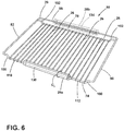
FIG. 6 is a top perspective view of an elongated member for a rack of the present disclosure; -
FIG. 7 is a front perspective view of racks of the present disclosure positioned within a cooking appliance; -
FIG. 8 is a top plan view of a rack of the present disclosure that has an elongated member disposed along a forward crossbar; -
FIG. 9 is a top perspective view of a rack of the present disclosure with an opening defined between an elongated member and a cross member; -
FIG. 10 is a front elevational view of an elongated member of the present disclosure; -
FIG. 11 is a side elevational view of a rack of the present disclosure; -
FIG. 12 is a top plan view of a rack of the present disclosure that has an elongated member integrally formed with a perimeter rim of the rack; -
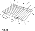
FIG. 13 is a top perspective view of a rack of the present disclosure with an opening defined between an elongated member and a cross member; -
FIG. 14 is a front elevational view of an elongated member of the present disclosure disposed between a first forward crossbar and a second forward crossbar; and -
FIG. 15 is a side elevational view of a rack of the present disclosure. - The components in the figures are not necessarily to scale, emphasis instead being placed upon illustrating the principles described herein.
- The present illustrated embodiments reside primarily in combinations apparatus components related to an elongated member for a rack. Accordingly, the apparatus components have been represented, where appropriate, by conventional symbols in the drawings, showing only those specific details that are pertinent to understanding the embodiments of the present disclosure so as not to obscure the disclosure with details that will be readily apparent to those of ordinary skill in the art having the benefit of the description herein. Further, like numerals in the description and drawings represent like elements.
- For purposes of description herein, the terms "upper," "lower," "right," "left," "rear," "front," "vertical," "horizontal," and derivatives thereof shall relate to the disclosure as oriented in
FIG. 1 . Unless stated otherwise, the term "front" shall refer to the surface of the element closer to an intended viewer, and the term "rear" shall refer to the surface of the element further from the intended viewer. However, it is to be understood that the disclosure may assume various alternative orientations, except where expressly specified to the contrary. It is also to be understood that the specific devices and processes illustrated in the attached drawings, and described in the following specification are simply exemplary embodiments of the inventive concepts defined in the appended claims. Hence, specific dimensions and other physical characteristics relating to the embodiments disclosed herein are not to be considered as limiting, unless the claims expressly state otherwise. - The terms "including," "comprises," "comprising," or any other variation thereof, are intended to cover a non-exclusive inclusion, such that a process, method, article, or apparatus that comprises a list of elements does not include only those elements but may include other elements not expressly listed or inherent to such process, method, article, or apparatus. An element proceeded by "comprises a ... " does not, without more constraints, preclude the existence of additional identical elements in the process, method, article, or apparatus that comprises the element.
- Referring to
FIGS. 1-15 ,reference numeral 10 generally designates a cooking appliance that includes abody 12 defining acavity 14 and a plurality ofretention rails 16. Arack 18 is operably coupled to theretention rails 16 of thebody 12 within thecavity 14. Therack 18 includes aperimeter rim 20 having afirst end 22 and asecond end 24. A plurality of spacedrails 26 are disposed between the first andsecond ends perimeter rim 20. Anelongated member 28 includes a display surface 30, an attachment surface 32, and an indicia 34 disposed on the display surface 30. Theelongated member 28 is operably coupled to a central region 36 of thefirst end 22 of theperimeter rim 20 proximate to the plurality of spacedrails 26 via the attachment surface 32 and divides thefirst end 22 at the central region 36. - Referring to
FIG. 1 , therack 18 is illustrated within thecooking appliance 10. Thecooking appliance 10 is illustrated as a built-in oven; however, it is also contemplated that therack 18 may be used in other cooking appliances such as microwaves, toaster ovens, ranges, and other similar cooking appliances. As illustrated inFIG. 1 , thecooking appliance 10 includes adoor 40 that is operably coupled to thebody 12 of thecooking appliance 10. Thebody 12 defines theinterior cavity 14 in which first and second support racks 50, 54 vertically extend. Stated differently, the first and second support racks 50, 54 vertically extend alongsidewalls 56 of thebody 12 within theinterior cavity 14. It is generally contemplated that the first and second support racks 50, 54 include the plurality ofretention rails 16 that each definerecesses 60 within which therack 18 may be placed, as described further below. - As illustrated in
FIGS. 1-6 , theperimeter rim 20 generally defines aframe 70 of therack 18. The spacedrails 26 are disposed within acentral portion 72 of therack 18 and extend between thefirst end 22 and thesecond end 24 of theperimeter rim 20, such that the spacedrails 26 are coupled to the first andsecond ends rails 26 may extend around the first andsecond ends perimeter rim 20. Additionally or alternatively, each rail may be operably coupled to the first andsecond ends rails 26 may abut the first andsecond ends central portion 72 of therack 18. Therails 26 may be operably coupled to theperimeter rim 20 via spot welding, casting, and/or other coupling methods generally known in the art. It is generally contemplated that thefirst end 22 of theperimeter rim 20 corresponds to aforward crossbar 74 of therack 18 and thesecond end 24 corresponds to arearward crossbar 78 of therack 18. - In addition, the
perimeter rim 20 has first and second side rails 82, 86. As illustrated inFIGS. 2-5 , each of the first and second side rails 82, 86 defines anotch 90, which further defines aprojection 94. Theprojection 94 of each of the first and second side rails 82, 86 are configured to operably couple therack 18 to the first and second support racks 50, 54, respectively. This coupling of theprojections 94 within therecesses 60 defined by the first and second support racks 50, 54 generally retains therack 18 within the retention rails 16, such that therack 18 is securely, but removably, coupled to each of the first and second support racks 50, 54. It is generally contemplated that a user would at least partially raise therack 18 so theprojections 94 can pass through therecesses 60 and over the retention rails 16 when removing therack 18 from theinterior cavity 14. When therack 18 is properly installed within theinterior cavity 14, theprojections 94 engage the retention rails 16 preventing horizontal removal of therack 18. Additionally, the illustratedrack 18 includes asupport rail 98, which may abut a rear portion of thebody 12 within theinterior cavity 14 and may provide additional structural support for therack 18. However, therack 18 may also be free of thesupport rail 98. - With further reference to
FIGS. 1-6 , theelongated member 28, as mentioned above, is generally coupled to at least thefirst end 22 of theperimeter rim 20. Typically, theelongated member 28 divides thefirst end 22 of theperimeter rim 20, but it is also contemplated that theelongated member 28 may extend along thefirst end 22 to conceal theforward crossbar 74. Theelongated member 28 can be formed from materials typically used in the formation of therack 18 including, but not limited to, stainless steel, chrome-plated carbon steel, nickel-plated steel, and other metallic materials. It is also advantageously contemplated that theelongated member 28 may be formed from an insulation material, such as silicon, to generally insulate theelongated member 28 relative to therack 18. Additionally or alternatively, the insulation material may be disposed and/or molded onto theelongated member 28, such that the insulation material defines a layer over theelongated member 28. The use of the insulation material for theelongated member 28 may allow a user to grasp theelongated member 28 to operably move therack 18 relative to thebody 12 of thecooking appliance 10 with minimal risk of the user contacting a thermally conductive material that may be hot. Thus, theelongated member 28 may provide an easily identifiable area at which a user can contact therack 18. - The first and second side rails 82, 86 are coupled to the
forward crossbar 74 and therearward crossbar 78 via anattachment feature 100. The attachment features 100 couple each of the first and second side rails 82, 86 to the forward andrearward crossbars arcuate portions 102 that are coupled to the forward andrearward crossbars linear portion 104 coupled to the first and second side rails 82, 86. Additionally, the attachment features 100 are configured to generally elevate at least a portion of the perimeter rim 20 relative to the spaced rails 26 disposed within thecentral portion 72 of therack 18. For example, thearcuate portions 102 curve generally upward from the forward andrearward crossbars linear portion 104 couples to thearcuate portions 102 and the first and second side rails 82, 86. Stated differently, thecentral portion 72 and the spaced rails 26 are generally depressed relative to at least a portion of theperimeter rim 20. Further, theperimeter rim 20 has theforward crossbar 74, which is contemplated to be generally planar with thecentral portion 72 and the spaced rails 26. - With further reference to
FIGS. 1-6 , theelongated member 28 is illustrated as at least partially extending along theforward crossbar 74. By way of example, not limitation, theelongated member 28 can extend along a length L1 of theforward crossbar 74, such that theforward crossbar 74 can be at least partially concealed along the length L1 of theforward crossbar 74 by theelongated member 28. In such configuration, afirst side 110 and asecond side 112 of theforward crossbar 74 are visible, while the central region 36 of theforward crossbar 74 is generally concealed. Theelongated member 28 can be coupled to theforward crossbar 74 via retention features 116. By way of example, not limitation, theelongated member 28 is illustrated as having first and second retention features 116a, 116b. However, theelongated member 28 may include asingle retention clip 116 or, optionally, a plurality of retention features 116. The retention features 116 may be clips, clasps, snaps, hooks, or other retention members generally known in the art. - As mentioned above, the
elongated member 28 can be said to extend between the attachment features 100 of the first and second side rails 82, 86. Theelongated member 28 is illustrated as being coupled to theforward crossbar 74. However, it is also contemplated that theelongated member 28 may be coupled to thearcuate portions 102 of the attachment features 100 to extend along and generally conceal theforward crossbar 74. Additionally or alternatively, theelongated member 28 may be operably coupled to therearward crossbar 78 of theperimeter rim 20, as illustrated in phantom. For example, theelongated member 28 may include a firstelongated member 28a and a secondelongated member 28b, such that the firstelongated member 28a is coupled to theforward crossbar 74 and the secondelongated member 28b can be coupled to therearward crossbar 78. It is also contemplated that the secondelongated member 28b can be coupled to thesupport rail 98 disposed behind therearward crossbar 78, as depicted inFIG. 3 . - With further reference to
FIGS. 1-6 , theelongated member 28 includes a display surface 30 and an attachment surface 32, with the retention features 116 typically coupled to the attachment surface 32. Theelongated member 28 is generally coupled to at least theforward crossbar 74 at the attachment surface 32 via the retention features 116. The display surface 30 of theelongated member 28 is configured to display the indicia 34, such as a logo, brand, brand name, and/or other descriptive indicia along a length L2 of theelongated member 28. Additionally or alternatively, the indicia 34 may be formed by theelongated member 28. While the firstelongated member 28a is typically coupled to theforward crossbar 74, it is generally contemplated that the secondelongated member 28b is coupled to either therearward crossbar 78 or thesupport rail 98. In such configuration, the display surface 30 is visible when thedoor 40 of thecooking appliance 10 is in an open position. - As illustrated in
FIGS. 2-5 , the display surface 30 and the attachment surface 32 of theelongated member 28 are generally defined by aperimeter edge 138 of theelongated member 28. In general, theperimeter edge 138 defines a boundary of theelongated member 28 that separates the display surface 30 and the attachment surface 32. Theperimeter edge 138 may be a planar surface, such that theperimeter edge 138 may be generally orthogonal with the attachment surface 32 and the display surface 30. Additionally or alternatively, theperimeter edge 138 may have a curved edge, such that the boundary between the display surface 30 and/or the attachment surface 32 is integral with theperimeter edge 138. It is also contemplated that the display surface 30 may extend around a circumference C1 of theelongated member 28, described in more detail below. - While the display surface 30 is typically defined as the surface display of the descriptive indicia 34, the attachment surface 32 of the second
elongated member 28b may alternatively be the surface on which the descriptive indicia 34 are disposed. For example, the attachment surface 32 of the secondelongated member 28b may include the descriptive indicia 34, described above, in addition to the descriptive indicia 34 disposed on the display surface 30. In one configuration, the display surface 30 is forward-facing relative to thecooking appliance 10 and the attachment surface 32 is rearward. In this configuration, the attachment surface 32 includes the retention features 116 to couple the secondelongated member 28b to thesupport rail 98 when the secondelongated member 28b is coupled to thesupport rail 98, and the descriptive indicia 34 may be disposed on both the attachment surface 32 and the display surface 30 of the secondelongated member 28b. In either configuration of the secondelongated member 28b, whether coupled to therearward crossbar 78 or thesupport rail 98, the indicia can be disposed upon the secondelongated member 28b to be visible when thedoor 40 of thecooking appliance 10 is in the open position. - As illustrated in
FIG. 6 , theelongated member 28 is wrapped around theforward crossbar 74 of therack 18. The attachment surface 32 of theelongated member 28 illustrated inFIG. 6 as defining agroove 140 in which theforward crossbar 74 can be disposed. It is generally contemplated that theelongated member 28 can be formed from a flexible, insulation material, such as silicon, such that theelongated member 28 can be disposed around theforward crossbar 74. As mentioned above, the display surface 30 in this configuration is defined by the circumference C1 of theelongated member 28. Stated differently, the indicia 34 can be disposed on the display surface 30 at various locations along the circumference C1 of theelongated member 28. - Referring now to
FIGS. 7-15 , therack 18 illustrated is generally defined within a single plane, such that theperimeter rim 20 and the spaced rails 26 are generally planar. As discussed above, the spaced rails 26 can extend around both theforward crossbar 74 and therearward crossbar 78. Additionally, thesupport rail 98 is forward of therearward crossbar 78. Thesupport rail 98 is positioned, such that the spaced rails 26 extend above thesupport rail 98. It is also contemplated that thesupport rail 98 may be disposed above the spaced rails 26. As depicted inFIGS. 8 and9 , thesupport rail 98 is coupled to the spaced rails 26 spanning thecentral portion 72 of therack 18. - The
projections 94, as generally described above, are illustrated inFIGS. 9 ,11 , and13 as pegs, which may be disposed within therecesses 60 of the first and second support racks 50, 54 positioned along the sides of thebody 12 of thecooking appliance 10. Similar to the operation described above, the user lifts therack 18 relative to the first and second support racks 50, 54 to remove the pegs from therecesses 60 defined by the retention rails 16. As opposed to theprojections 94 depicted inFIGS. 3 and5 , the pegs are generally disposed at both thefirst end 22 and thesecond end 24 of theperimeter rim 20. Additionally or alternatively, theprojections 94 may be disposed along any portion of the first and second side rails 82, 86 of theperimeter rim 20. - With further reference to
FIGS. 7-15 and as also described above with respect toFIGS. 2-4 , the spaced rails 26 may extend around the first and second ends 22, 24 of theperimeter rim 20. Comparatively, inFIGS. 8-10 and12-14 , the spaced rails 26 may both extend around the first and second ends 22, 24 as well as abut and couple to across member 146. Thecross member 146 is generally centrally and forwardly disposed on therack 18 and extends between afirst rail 26a and asecond rail 26b of the plurality of spaced rails 26. Thecross member 146 generally corresponds to the length L2 of theelongated member 28, such that a length L3 of thecross member 146 is generally similar to the length L2 of theelongated member 28. Additionally or alternatively, the length L3 of thecross member 146 may differ from the length L2 of theelongated member 28. The arrangement of theelongated member 28 and thecross member 146, along with the first andsecond rails opening 150 disposed directly behind theelongated member 28 and along the lengths L2, L3 of theelongated member 28 and thecross member 146, respectively. - In operation, a user may grasp the
elongated member 28 through theopening 150 defined behind theelongated member 28 and proximate to thecross member 146. Typically, when theelongated member 28 is used as a handle, as described, theelongated member 28 is formed from the insulation material that has low thermal conductivity. However, as discussed above, it is also contemplated that theelongated member 28 may be formed from the same material as therack 18. When therack 18 and theelongated member 28 are formed from the same material, it is contemplated that theelongated member 28 is integrally formed with therack 18, as illustrated inFIGS. 12-14 . With such integration, the user typically utilizes some form of insulating material in order to grasp theelongated member 28 to minimize potential contact with a thermally conductive material. - Referring now to
FIGS. 8-11 , the attachment surface 32 of theelongated member 28 defines thegroove 140, mentioned above, that is configured to receive theforward crossbar 74 of theperimeter rim 20. In such configuration, theelongated member 28 is configured to snap-fit to theforward crossbar 74 of theperimeter rim 20. While theelongated member 28 may be removably coupled to theforward crossbar 74, it is generally contemplated that theelongated member 28 remains fixedly coupled to theforward crossbar 74. Thus, theelongated member 28 remains securely attached to the perimeter rim 20 during articulation of therack 18. - The display surface 30 may extend around the
elongated member 28, such that the display surface 30 may correspond to the previously described perimeter edge 138 (FIG. 2 ) of theelongated member 28. Accordingly, the descriptive indicia 34 may be disposed along an upper display surface 30a, a front display surface 30b, and a lower display surface 30c of theelongated member 28. The additional display surfaces 30a-30c of theelongated member 28 provide additional space upon which descriptive indicia 34 may be disposed. For example, a brand name may be disposed along the front display surface 30b, while the brand logo or other image-based indicia may be disposed along the upper and/or lower display surfaces 30a, 30c of theelongated member 28. Additionally or alternatively, the brand logo or other image-based indicia may be disposed along the front display surface 30b, and the brand name may be disposed along the upper and/or lower display surfaces 30a, 30c. The additional display surfaces 30a-30c provides an increased area of display for the brand information and/or other descriptive indicia 34 to be displayed on theelongated member 28 via one of the display surfaces 30a-30c. However, the indicia 34 are not limited by the arrangements relative to the display surfaces 30a-30c as described above. - As depicted in
FIG. 9 , theelongated member 28 generally forms a C-shape, which helps to define thegroove 140 along the attachment surface 32 of theelongated member 28. Theelongated member 28 depicted inFIGS. 8-10 has a generally rectangular and angular shape, such that each of the display surfaces 30a-30c are clearly defined. Additionally or alternatively, the display surface 30 of theelongated member 28 may be generally arcuate relative to thefirst end 22 of theperimeter rim 20, similar to theelongated member 28 depicted inFIGS. 12-14 , described in more detail below. The arcuate display surface 30 can partially extend around a circumference C1 (FIG. 13 ) of theelongated member 28. Accordingly, the descriptive indicia 34 may extend along the arcuate display surface 30, while theelongated member 28 is operably coupled to theforward crossbar 74 via thegroove 140 defined by the attachment surface 32, in contrast to the construction of theelongated member 28 described in further detail with reference toFIGS. 12-15 . - Referring now to
FIGS. 12-15 , theelongated member 28 may be integrally formed with theperimeter rim 20, such that theforward crossbar 74 includes a firstforward crossbar 74a and a secondforward crossbar 74b with theelongated member 28 disposed therebetween. In such construction, the first andsecond rails rails 26 are also coupled to theelongated member 28 at a first attachment surface 32a and a second attachment surface 32b, respectively. Theelongated member 28 can be generally cylindrical such that the display surface 30 extends around the circumference C1 of theelongated member 28. Accordingly, the indicia 34 described above may be disposed along any portion of theelongated member 28. Stated differently, the indicia 34 may be disposed along the display surface 30 and generally around theelongated member 28, as the display surface 30 generally wraps around the circumference C1 of theelongated member 28. - Rather than couple via retention features 116 (
FIG. 2 ), theelongated member 28 depicted inFIG. 12 couples to the first andsecond rails elongated member 28 may be integrally formed with the perimeter rim 20 at the first and second attachment surfaces 32a, 32b. As a result of this integration of theelongated member 28, the first andsecond forward crossbars elongated member 28. Accordingly, theelongated member 28, as illustrated, at least partially defines theframe 70 as part of theperimeter rim 20. - Referring still to
FIGS. 12-15 , it is also contemplated that theelongated member 28 may be rotatably coupled to the first andsecond forward crossbars perimeter rim 20, such that the display surface 30 may rotate about an axis X relative to the first andsecond forward crossbars second forward crossbars - With further reference to
FIGS. 1-15 , it is generally advantageous that theelongated member 28 provides a display surface 30 upon which a brand, logo, and/or other descriptive indicia 34 may be displayed, such that a user may readily identify the associated brand via theelongated member 28. Moreover, theelongated member 28 may provide decorative advantages for therack 18 when positioned within thebody 12 of thecooking appliance 10. For example, when placing items in thecooking appliance 10, a user can readily identify the brand of thecooking appliance 10 based on the indicia 34 located on the display surface 30 of theelongated member 28. Theelongated member 28 can also provide the user with a readily identifiable area to grasp therack 18 when articulating therack 18 relative to thebody 12 of thecooking appliance 10. - According to one aspect of the present disclosure, a cooking appliance includes a body that defines a cavity and a plurality of retention rails. A rack is operably coupled to the retention rails of the body within the cavity. The rack includes a perimeter rim that has a first end and a second end. A plurality of spaced rails are disposed between the first end and the second end of the perimeter rim, and an elongated member includes a display surface, an attachment surface, and an indicia disposed on the display surface. The elongated member is operably coupled to a central region of the first end of the perimeter rim proximate to the plurality of spaced rails via the attachment surface and divides the first end at the central region.
- According to another aspect, an elongated member is formed from an insulation material.
- According to another aspect, an elongated member includes retention features that are disposed on the attachment surface.
- According to another aspect, a display surface includes a first display surface and a second display surface. An indicia is disposed on each of the first display surface and the second display surface.
- According to another aspect, an elongated member is operably coupled to a perimeter rim of a rack via retention features.
- According to another aspect, an attachment surface that defines a groove along a length of the elongated member.
- According to another aspect, a perimeter rim of a rack is disposed within a groove of an attachment surface.
- According to another aspect of the present disclosure, an appliance includes a body that defines a cavity and includes a first retention rail and a second retention rail. A rack has a first side rail that is operably coupled to the first retention rail, and a second retention side rail that is operably coupled to the second retention rail. The rack includes a plurality of spaced rails that are disposed between the first and second side rails of the rack. An elongated member is operably coupled to the rack that is proximate to the plurality of spaced rails. The elongated member includes an attachment surface and a display surface separated by a perimeter edge
- According to another aspect, a rack includes attachment features, a forward crossbar, and a rearward crossbar. The attachment features couple each first and second side rail to each of the forward and rearward crossbars.
- According to another aspect, a rack includes a perimeter rim, and at least a portion of the perimeter rim is disposed above an elongated member and a plurality of spaced rails of a rack via attachment features.
- According to another aspect, a rack defines an opening that is disposed behind an elongated member and along a length of the elongated member and a length of the rack.
- According to another aspect, an elongated member is comprised of an insulation material.
- According to another aspect, an attachment surface defines a groove along a length of the elongated member.
- According to another aspect, a perimeter rim of a rack is disposed within a groove of an attachment surface.
- According to another aspect of the present disclosure, a rack for a cooking appliance includes a perimeter rim that has a first end, a second end, a first side rail, and a second side rail. A plurality of spaced rails are disposed between each of the first and second rails and the first and second ends of the perimeter rim. An elongated member is operably coupled to the perimeter rim and is proximate to the plurality of spaced rails. A crossbar is disposed proximate to the elongated member. The crossbar defines an opening directly behind the elongated member along a length of the elongated member and a length of the crossbar.
- According to another aspect, an elongated member includes a display surface and an attachment surface.
- According to another aspect, an indicia is disposed on a display surface of an elongated member.
- According to another aspect, an elongated member includes a perimeter edge that separates a display surface and an attachment surface.
- According to another aspect, a display surface extends around a circumference of an elongated member.
- According to another aspect, an elongated member includes an attachment surface that defines a groove along a length of the elongated member. The elongated member is coupled to a perimeter rim via a groove of an attachment surface.
Claims (15)
- A cooking appliance (10), comprising:a body (12) defining a cavity (14) and including a first retention rail (116a) and a second retention rail (116b);a rack (18) having a first side rail (82) operably coupled to the first retention rail (116a) and a second side rail (86) operably coupled to the second retention rail (116b), the rack (18) including a plurality of spaced rails (26) disposed between the first and second side rails (82, 86) of the rack (18); andan elongated member (28) operably coupled to the rack (18) proximate to the plurality of spaced rails (26), the elongated member (28) including an attachment surface (32) and a display surface (30) separated by a perimeter edge (138).
- The cooking appliance (10) of claim 1, wherein the rack (18) includes attachment features (100), a forward crossbar (74), and a rearward crossbar (78), and wherein the attachment features (100) couple each of the first and second side rails (82, 86) to each of the forward and rearward crossbars (74, 78).
- The cooking appliance (10) of either of claims 1 and 2, wherein the rack (18) includes a perimeter rim (20).
- The cooking appliance (10) of claims 2 and 3, wherein at least a portion of the perimeter rim (20) is disposed above the elongated member (28) and the plurality of spaced rails (26) of the rack (18) via the attachment features (100).
- The cooking appliance (10) of any one of claims 1-4, wherein the elongated member (28) includes retention features (116) disposed on the attachment surface (32).
- The cooking appliance (10) of claims 3 and 5, wherein the elongated member (28) is operably coupled to the perimeter rim (20) of the rack (18) via the retention features (116).
- The cooking appliance (10) of any one of claims 1-6, wherein the attachment surface (32) defines a groove (140) along a length of the elongated member (28).
- The cooking appliance (10) of claim 7, wherein the perimeter rim (20) of the rack (18) is disposed within the groove (140) of the attachment surface (32).
- The cooking appliance (10) of claims 3 and 7, wherein the elongated member (28) is coupled to the perimeter rim (20) via the groove (140) of the attachment surface (32).
- The cooking appliance (10) of any one of claims 1-9, further comprising:
an indicia (34) disposed on the display surface (30) of the elongated member (28). - The cooking appliance (10) of any one of claims 1-10, wherein the display surface (30) includes a first display surface (30a) and a second display surface (30b).
- The cooking appliance (10) of claims 10 and 11, wherein the indicia (34) is disposed on each of the first display surface (30a) and the second display surface (30b).
- The cooking appliance (10) of any one of claims 1-12, wherein the display surface (30) extends around a circumference of the elongated member (28).
- The cooking appliance (10) of any one of claims 1-13, wherein the rack (18) defines an opening (150) disposed behind the elongated member (28) and along a length of the elongated member (28) and a length of the rack (18).
- The cooking appliance (10) of any one of claims 1-14, wherein the elongated member (28) is formed from silicone.
Applications Claiming Priority (2)
| Application Number | Priority Date | Filing Date | Title |
|---|---|---|---|
| US202062962664P | 2020-01-17 | 2020-01-17 | |
| US17/147,509 US11561011B2 (en) | 2020-01-17 | 2021-01-13 | Elongated member for a rack |
Publications (1)
| Publication Number | Publication Date |
|---|---|
| EP3851747A1 true EP3851747A1 (en) | 2021-07-21 |
Family
ID=74186558
Family Applications (1)
| Application Number | Title | Priority Date | Filing Date |
|---|---|---|---|
| EP21151954.1A Withdrawn EP3851747A1 (en) | 2020-01-17 | 2021-01-15 | Cooking oven with a rack having an elongated member |
Country Status (2)
| Country | Link |
|---|---|
| US (1) | US11561011B2 (en) |
| EP (1) | EP3851747A1 (en) |
Cited By (1)
| Publication number | Priority date | Publication date | Assignee | Title |
|---|---|---|---|---|
| US20240230107A9 (en) * | 2022-10-24 | 2024-07-11 | Whirlpool Corporation | Divider assembly |
Families Citing this family (4)
| Publication number | Priority date | Publication date | Assignee | Title |
|---|---|---|---|---|
| US12242289B2 (en) * | 2022-01-10 | 2025-03-04 | Whirlpool Corporation | Temperature sensors for a cooking appliance |
| US12035845B1 (en) | 2023-04-26 | 2024-07-16 | Sharkninja Operating Llc | Systems and methods for cooking pizza |
| US12372247B2 (en) | 2023-04-26 | 2025-07-29 | Sharkninja Operating Llc | Systems and methods for cooking pizza |
| USD1104596S1 (en) | 2023-05-31 | 2025-12-09 | Sharkninja Operating Llc | Cooking device |
Citations (5)
| Publication number | Priority date | Publication date | Assignee | Title |
|---|---|---|---|---|
| US2806467A (en) * | 1955-05-18 | 1957-09-17 | Roy E Slaughter | Oven shelf |
| US3977389A (en) * | 1975-04-16 | 1976-08-31 | Ondrasik Ii Vladimir J | Rack constraining apparatus |
| US20090064989A1 (en) * | 2007-09-06 | 2009-03-12 | Timothy Scott Shaffer | Oven Rack Apparatus and Corresponding Method |
| GB2455541A (en) * | 2007-12-12 | 2009-06-17 | Guy Darell Unwin | Tubular thermal guard for oven shelf |
| US20190003723A1 (en) * | 2017-06-29 | 2019-01-03 | Midea Group Co., Ltd. | Handle for a rack support structure |
Family Cites Families (20)
| Publication number | Priority date | Publication date | Assignee | Title |
|---|---|---|---|---|
| US1822641A (en) * | 1930-04-28 | 1931-09-08 | Clifton H Angell | Price tag and sign |
| US1994144A (en) * | 1931-04-28 | 1935-03-12 | Goodrich Co B F | Cathode insulation |
| US2169904A (en) * | 1936-10-26 | 1939-08-15 | Gen Motors Corp | Thermometer bracket |
| US2186857A (en) * | 1937-08-04 | 1940-01-09 | Robert F Davis | Domestic oven |
| DE8915074U1 (en) | 1989-12-22 | 1990-02-22 | H. Zenker GmbH & Co. KG, Metallwarenfabrik, 8890 Aichach | Extendable roasting or grill rack for ovens |
| US5429377A (en) * | 1993-04-15 | 1995-07-04 | Duer; Sandra D. | Sanitary protective covers for shopping cart use |
| US6112916A (en) * | 1999-08-24 | 2000-09-05 | Maytag Corporation | Oven rack |
| US6644302B1 (en) * | 2000-05-09 | 2003-11-11 | Barson Enterprises, Inc. | Oven rack |
| US7673628B1 (en) | 2003-05-01 | 2010-03-09 | JAZ Innovations, LLC | Oven rack guard |
| US7347198B2 (en) | 2004-03-19 | 2008-03-25 | Whirlpool Corporation | Oven rack |
| US7472796B2 (en) | 2004-03-31 | 2009-01-06 | Electrolux Home Products, Inc. | Appliance rack with handle |
| US20060102015A1 (en) * | 2004-11-12 | 2006-05-18 | Bsh Home Appliances Corporation | Retractable oven rack assembly |
| GB0603696D0 (en) * | 2006-02-24 | 2006-04-05 | Packaging Innovation Ltd | A handle arrangement |
| JP5042545B2 (en) * | 2006-07-05 | 2012-10-03 | パナソニックヘルスケア株式会社 | Shelf device and incubator having the same |
| US9587838B2 (en) | 2006-11-30 | 2017-03-07 | Ssw Holding Company, Inc. | Oven rack assemblies with release mechanisms and catches |
| US8820314B1 (en) | 2010-09-23 | 2014-09-02 | Nashville Wire Products Mfg. Co. | Extendible oven rack apparatus |
| US9149119B2 (en) * | 2012-10-18 | 2015-10-06 | Customer Motivators, Llc | Ventilated shelf cover with spring clasp |
| US9671115B2 (en) | 2012-11-20 | 2017-06-06 | Bsh Home Appliances Corporation | Home appliance with a telescopic rack |
| CN106678905B (en) * | 2016-12-20 | 2019-07-26 | 广东美的厨房电器制造有限公司 | Microwave heating electric appliance |
| EP3926241A1 (en) * | 2020-06-17 | 2021-12-22 | BSH Hausgeräte GmbH | Cooking tray |
-
2021
- 2021-01-13 US US17/147,509 patent/US11561011B2/en active Active
- 2021-01-15 EP EP21151954.1A patent/EP3851747A1/en not_active Withdrawn
Patent Citations (5)
| Publication number | Priority date | Publication date | Assignee | Title |
|---|---|---|---|---|
| US2806467A (en) * | 1955-05-18 | 1957-09-17 | Roy E Slaughter | Oven shelf |
| US3977389A (en) * | 1975-04-16 | 1976-08-31 | Ondrasik Ii Vladimir J | Rack constraining apparatus |
| US20090064989A1 (en) * | 2007-09-06 | 2009-03-12 | Timothy Scott Shaffer | Oven Rack Apparatus and Corresponding Method |
| GB2455541A (en) * | 2007-12-12 | 2009-06-17 | Guy Darell Unwin | Tubular thermal guard for oven shelf |
| US20190003723A1 (en) * | 2017-06-29 | 2019-01-03 | Midea Group Co., Ltd. | Handle for a rack support structure |
Cited By (1)
| Publication number | Priority date | Publication date | Assignee | Title |
|---|---|---|---|---|
| US20240230107A9 (en) * | 2022-10-24 | 2024-07-11 | Whirlpool Corporation | Divider assembly |
Also Published As
| Publication number | Publication date |
|---|---|
| US11561011B2 (en) | 2023-01-24 |
| US20210222888A1 (en) | 2021-07-22 |
Similar Documents
| Publication | Publication Date | Title |
|---|---|---|
| US11561011B2 (en) | Elongated member for a rack | |
| US8899426B2 (en) | Half rack | |
| US5148755A (en) | Utility tray for attachment to a wall, or the like | |
| US3115107A (en) | Combination condiment rack and barbecue tool holders | |
| US7878344B2 (en) | Tuck and store rack | |
| CN101069054B (en) | Shelf, particularly for refrigeration units, which is designed to support at least one accessory and corresponding accessories | |
| US6349717B1 (en) | Oven rack system having cutout area and insert rack | |
| US5339728A (en) | Cooking rack for a pan | |
| CA2597187C (en) | Full depth rack | |
| US8820314B1 (en) | Extendible oven rack apparatus | |
| US7122765B2 (en) | Electric oven | |
| US7823735B2 (en) | Handle rack | |
| US5301909A (en) | Stove carrier | |
| US3706302A (en) | Continuous clean oven conversion | |
| CA2535915A1 (en) | Floor assembly for grill | |
| US20050217494A1 (en) | Handling assembly | |
| CA2242118A1 (en) | Partial width oven rack | |
| US3586411A (en) | Display rack | |
| JPH11259A (en) | Cooking pot and pot lid supporter | |
| KR20190082642A (en) | A support for lid of vooking vessel | |
| US2802927A (en) | Surface heating unit | |
| FR2504371A1 (en) | Drawer for pharmacy cabinet - has transverse partitions each with inverted U=shaped clips fitting over edges of drawer | |
| WO2009007729A1 (en) | Baking tray | |
| US2694610A (en) | Detachably mounted tray for automobiles | |
| US2049717A (en) | Electric toaster |
Legal Events
| Date | Code | Title | Description |
|---|---|---|---|
| PUAI | Public reference made under article 153(3) epc to a published international application that has entered the european phase |
Free format text: ORIGINAL CODE: 0009012 |
|
| STAA | Information on the status of an ep patent application or granted ep patent |
Free format text: STATUS: THE APPLICATION HAS BEEN PUBLISHED |
|
| AK | Designated contracting states |
Kind code of ref document: A1 Designated state(s): AL AT BE BG CH CY CZ DE DK EE ES FI FR GB GR HR HU IE IS IT LI LT LU LV MC MK MT NL NO PL PT RO RS SE SI SK SM TR |
|
| STAA | Information on the status of an ep patent application or granted ep patent |
Free format text: STATUS: THE APPLICATION IS DEEMED TO BE WITHDRAWN |
|
| 18D | Application deemed to be withdrawn |
Effective date: 20220122 |