EP3851742A1 - Systems and methods for mitigating condensation in aircraft lighting - Google Patents
Systems and methods for mitigating condensation in aircraft lighting Download PDFInfo
- Publication number
- EP3851742A1 EP3851742A1 EP21151693.5A EP21151693A EP3851742A1 EP 3851742 A1 EP3851742 A1 EP 3851742A1 EP 21151693 A EP21151693 A EP 21151693A EP 3851742 A1 EP3851742 A1 EP 3851742A1
- Authority
- EP
- European Patent Office
- Prior art keywords
- housing
- article
- manufacture
- heat source
- transport apparatus
- Prior art date
- Legal status (The legal status is an assumption and is not a legal conclusion. Google has not performed a legal analysis and makes no representation as to the accuracy of the status listed.)
- Granted
Links
Images

Classifications
-
- B—PERFORMING OPERATIONS; TRANSPORTING
- B64—AIRCRAFT; AVIATION; COSMONAUTICS
- B64D—EQUIPMENT FOR FITTING IN OR TO AIRCRAFT; FLIGHT SUITS; PARACHUTES; ARRANGEMENT OR MOUNTING OF POWER PLANTS OR PROPULSION TRANSMISSIONS IN AIRCRAFT
- B64D47/00—Equipment not otherwise provided for
- B64D47/02—Arrangements or adaptations of signal or lighting devices
-
- F—MECHANICAL ENGINEERING; LIGHTING; HEATING; WEAPONS; BLASTING
- F21—LIGHTING
- F21V—FUNCTIONAL FEATURES OR DETAILS OF LIGHTING DEVICES OR SYSTEMS THEREOF; STRUCTURAL COMBINATIONS OF LIGHTING DEVICES WITH OTHER ARTICLES, NOT OTHERWISE PROVIDED FOR
- F21V29/00—Protecting lighting devices from thermal damage; Cooling or heating arrangements specially adapted for lighting devices or systems
- F21V29/50—Cooling arrangements
- F21V29/502—Cooling arrangements characterised by the adaptation for cooling of specific components
- F21V29/508—Cooling arrangements characterised by the adaptation for cooling of specific components of electrical circuits
-
- F—MECHANICAL ENGINEERING; LIGHTING; HEATING; WEAPONS; BLASTING
- F21—LIGHTING
- F21V—FUNCTIONAL FEATURES OR DETAILS OF LIGHTING DEVICES OR SYSTEMS THEREOF; STRUCTURAL COMBINATIONS OF LIGHTING DEVICES WITH OTHER ARTICLES, NOT OTHERWISE PROVIDED FOR
- F21V29/00—Protecting lighting devices from thermal damage; Cooling or heating arrangements specially adapted for lighting devices or systems
- F21V29/50—Cooling arrangements
- F21V29/51—Cooling arrangements using condensation or evaporation of a fluid, e.g. heat pipes
-
- F—MECHANICAL ENGINEERING; LIGHTING; HEATING; WEAPONS; BLASTING
- F21—LIGHTING
- F21V—FUNCTIONAL FEATURES OR DETAILS OF LIGHTING DEVICES OR SYSTEMS THEREOF; STRUCTURAL COMBINATIONS OF LIGHTING DEVICES WITH OTHER ARTICLES, NOT OTHERWISE PROVIDED FOR
- F21V29/00—Protecting lighting devices from thermal damage; Cooling or heating arrangements specially adapted for lighting devices or systems
- F21V29/90—Heating arrangements
-
- F—MECHANICAL ENGINEERING; LIGHTING; HEATING; WEAPONS; BLASTING
- F21—LIGHTING
- F21V—FUNCTIONAL FEATURES OR DETAILS OF LIGHTING DEVICES OR SYSTEMS THEREOF; STRUCTURAL COMBINATIONS OF LIGHTING DEVICES WITH OTHER ARTICLES, NOT OTHERWISE PROVIDED FOR
- F21V23/00—Arrangement of electric circuit elements in or on lighting devices
- F21V23/003—Arrangement of electric circuit elements in or on lighting devices the elements being electronics drivers or controllers for operating the light source, e.g. for a LED array
- F21V23/007—Arrangement of electric circuit elements in or on lighting devices the elements being electronics drivers or controllers for operating the light source, e.g. for a LED array enclosed in a casing
-
- F—MECHANICAL ENGINEERING; LIGHTING; HEATING; WEAPONS; BLASTING
- F21—LIGHTING
- F21V—FUNCTIONAL FEATURES OR DETAILS OF LIGHTING DEVICES OR SYSTEMS THEREOF; STRUCTURAL COMBINATIONS OF LIGHTING DEVICES WITH OTHER ARTICLES, NOT OTHERWISE PROVIDED FOR
- F21V31/00—Gas-tight or water-tight arrangements
- F21V31/03—Gas-tight or water-tight arrangements with provision for venting
-
- F—MECHANICAL ENGINEERING; LIGHTING; HEATING; WEAPONS; BLASTING
- F21—LIGHTING
- F21W—INDEXING SCHEME ASSOCIATED WITH SUBCLASSES F21K, F21L, F21S and F21V, RELATING TO USES OR APPLICATIONS OF LIGHTING DEVICES OR SYSTEMS
- F21W2107/00—Use or application of lighting devices on or in particular types of vehicles
- F21W2107/30—Use or application of lighting devices on or in particular types of vehicles for aircraft
-
- F—MECHANICAL ENGINEERING; LIGHTING; HEATING; WEAPONS; BLASTING
- F21—LIGHTING
- F21Y—INDEXING SCHEME ASSOCIATED WITH SUBCLASSES F21K, F21L, F21S and F21V, RELATING TO THE FORM OR THE KIND OF THE LIGHT SOURCES OR OF THE COLOUR OF THE LIGHT EMITTED
- F21Y2115/00—Light-generating elements of semiconductor light sources
- F21Y2115/10—Light-emitting diodes [LED]
Definitions
- the present disclosure relates generally to aircraft systems and, more particularly, to aircraft exterior lighting systems.
- Aircraft exterior lights are expected to endure a wide range of atmospheric and environmental conditions including combinations of temperature, pressure, humidity, and exposure to liquid water such as rain. Operating conditions of aircraft exterior lights may tend to promote condensation of liquid water within the light unit housing. Condensation within the light unit is undesirable, tending to reduce emissivity of lighting elements and promote electrical malfunctions.
- an exterior lamp for an aircraft comprises a housing defining an interior volume, a heat source disposed within the interior volume of the housing, a light source disposed within the housing configured to emit a light therefrom, a protective lens coupled to the housing proximate the light source, wherein the protective lens is configured to transmit the light, and a capillary transport apparatus having a first end and a second end, wherein the first end is coupled to the heat source and the second end is disposed in a catchment basin.
- the catchment basement is defined by the protective lens.
- the heat source is a driver board configured to drive the light source.
- the first end is coupled to a heat sink of the driver board.
- the protective lens encloses a reflector wherein the second end of the capillary transport apparatus extends through the reflector into the catchment basin.
- a vapor permeable membrane is in fluid communication between the interior volume of the housing and an exterior of the housing.
- the capillary transport apparatus comprises one of a wick, a woven material, a fibrous material, or a braided material
- an article of manufacture comprising a housing defining an interior volume a heat source disposed within the interior volume of the housing, and a capillary transport apparatus having a first end and a second end, wherein the first end is coupled to the heat source and the second end is disposed in a catchment basin.
- the catchment basin is defined by the housing.
- a light source is disposed within the housing and configured to emit a light.
- a protective lens is configured to transmit the light from the light source.
- the catchment basin is defined by the protective lens.
- the heat source is a driver board configured to drive the light source.
- the first end is coupled to a heat sink of the driver board.
- the protective lens encloses a reflector, wherein the second end of the capillary transport apparatus extends through the reflector.
- the capillary transport apparatus is coupled to the heat source by bonding.
- the capillary transport apparatus is coupled to the heat source by a friction coupling.
- the capillary transport apparatus comprises one of a wick, a woven material, a fibrous material, or a braided material.
- a vapor permeable membrane is in fluid communication between the interior volume of the housing and an exterior of the housing.
- a method of mitigating condensation within a housing comprises collecting a condensate within a catchment basin, wicking the condensate from the catchment basin to a heat source, evaporating the condensate to generate a vapor, and diffusing the vapor through a transport path in fluid communication with an interior volume of the housing.
- any of the method or process descriptions may be executed in any order and are not necessarily limited to the order presented.
- any reference to singular includes plural embodiments, and any reference to more than one component or step may include a singular embodiment or step.
- any reference to attached, fixed, coupled, connected or the like may include permanent, removable, temporary, partial, full and/or any other possible attachment option.
- any reference to without contact (or similar phrases) may also include reduced contact or minimal contact. Surface shading lines may be used throughout the figures to denote different parts but not necessarily to denote the same or different materials.
- Aircraft 10 comprises a fuselage 12, wings 14, empennage 16, landing gear 18, a propulsion system, such as gas turbine engines 20, and a plurality of exterior lights 22.
- Exterior lights 22 may include any number of lights know to those skilled in the art such as, for example, navigation lights, logo lights, wing scan lights, runway turnoff lights, cargo loading lights, engine scan lights, anti-collision strobe lights, beacon lights, and/or the like. It will be appreciated that the number and location of the exterior lights 22 are exemplary and aircraft 10 may include any number of additional lights which may be beneficial to operation of aircraft 10 but are not illustrated.
- Exterior light 22 may comprise a housing 200 defining an interior volume 202. Exterior light 22 incudes a light source 216 configured to emit a light such as, for example, an array of light emitting diodes (LEDs).
- a heat source 204 is disposed within the interior volume 202 of the housing 200.
- a capillary transport apparatus 206 may be coupled to the heat source 204. The capillary transport apparatus 206 may be coupled to the heat source 204 at a first end 208. A second end 210 of the capillary transport apparatus 206 may extend into a catchment basin 212.
- the capillary transport apparatus 206 may be coupled by one of bonding, staking, pinning, or by a friction coupling 228 such as, for example, one of a clamp, a ferrule, a crimp, and/or the like.
- the catchment basin 212 may be defined by the housing 200.
- a condensate 214 may form within the interior volume 202 of housing 200 and tend to collect within the catchment basin 212.
- the capillary transport apparatus 206 may comprise one of a wick, a woven material, a fibrous material, a braided material, or any other sort of material understood to promote capillary transportation of the condensate from the catchment basin 212 toward the heat source 204.
- the light source 216 may be protected by a protective lens 218 configured to emit the light from the light source 216.
- the protective lens may be sealed to the housing 200 such as, for example, by a seal ring 220.
- the protective lens 218 may define the catchment basin 212.
- the protective lens 218 may enclose a reflector 222 configured to reflect the light from the light source 216.
- the reflector 222 may have an annular structure and the second end 210 of the capillary transport apparatus 206 may extend through an annulus of the reflector 222.
- a driver board 224 may be configured to drive the light source 216.
- the driver board 224 may comprise the heat source 204 and may be coupled to a heat sink 226 which may tend to receive thermal energy from the heat source 204.
- the first end 208 of the capillary transport apparatus 206 may be coupled to the heat sink 226.
- the condensate 214 may tend to collect in the catchment basin 212 and be wicked by the capillary transport apparatus 206 from the catchment basin 212 toward the heat source 204.
- the heat source 204 may tend to evaporate the condensate 214 to generate a vapor which may diffuse throughout the interior volume 202 of the housing 200.
- the housing 200 may comprise a vapor permeable membrane 230 in fluid communication between the interior volume 202 and the external environment (i.e., the exterior of the housing 200).
- the housing 200 includes a transport path for the vapor to diffuse from the interior volume 202 of the housing 200 and thereby exit the housing 200.
- the seal ring 220 may comprise a vapor permeable membrane.
- the evaporated vapor may tend to diffuse through the vapor permeable membrane 230 and thereby exit the exterior light 22.
- references to "various embodiments,” “one embodiment,” “an embodiment,” “an example embodiment,” etc. indicate that the embodiment described may include a particular feature, structure, or characteristic, but every embodiment may not necessarily include the particular feature, structure, or characteristic. Moreover, such phrases are not necessarily referring to the same embodiment. Further, when a particular feature, structure, or characteristic is described in connection with an embodiment, it is submitted that it is within the knowledge of one skilled in the art to affect such feature, structure, or characteristic in connection with other embodiments whether or not explicitly described. After reading the description, it will be apparent to one skilled in the relevant art(s) how to implement the disclosure in alternative embodiments.
Landscapes
- Engineering & Computer Science (AREA)
- General Engineering & Computer Science (AREA)
- Aviation & Aerospace Engineering (AREA)
- Non-Portable Lighting Devices Or Systems Thereof (AREA)
- Arrangement Of Elements, Cooling, Sealing, Or The Like Of Lighting Devices (AREA)
Abstract
Description
- The present disclosure relates generally to aircraft systems and, more particularly, to aircraft exterior lighting systems.
- Aircraft exterior lights are expected to endure a wide range of atmospheric and environmental conditions including combinations of temperature, pressure, humidity, and exposure to liquid water such as rain. Operating conditions of aircraft exterior lights may tend to promote condensation of liquid water within the light unit housing. Condensation within the light unit is undesirable, tending to reduce emissivity of lighting elements and promote electrical malfunctions.
- In various embodiments, an exterior lamp for an aircraft comprises a housing defining an interior volume, a heat source disposed within the interior volume of the housing, a light source disposed within the housing configured to emit a light therefrom, a protective lens coupled to the housing proximate the light source, wherein the protective lens is configured to transmit the light, and a capillary transport apparatus having a first end and a second end, wherein the first end is coupled to the heat source and the second end is disposed in a catchment basin.
- In various embodiments, the catchment basement is defined by the protective lens. In various embodiments, the heat source is a driver board configured to drive the light source. In various embodiments, the first end is coupled to a heat sink of the driver board. In various embodiments, the protective lens encloses a reflector wherein the second end of the capillary transport apparatus extends through the reflector into the catchment basin. In various embodiments, a vapor permeable membrane is in fluid communication between the interior volume of the housing and an exterior of the housing. In various embodiments, the capillary transport apparatus comprises one of a wick, a woven material, a fibrous material, or a braided material
- In various embodiments, an article of manufacture is disclosed comprising a housing defining an interior volume a heat source disposed within the interior volume of the housing, and a capillary transport apparatus having a first end and a second end, wherein the first end is coupled to the heat source and the second end is disposed in a catchment basin.
- In various embodiments, the catchment basin is defined by the housing. In various embodiments, a light source is disposed within the housing and configured to emit a light. In various embodiments, a protective lens is configured to transmit the light from the light source. In various embodiments, the catchment basin is defined by the protective lens. In various embodiments, the heat source is a driver board configured to drive the light source. In various embodiments, the first end is coupled to a heat sink of the driver board. In various embodiments, the protective lens encloses a reflector, wherein the second end of the capillary transport apparatus extends through the reflector. In various embodiments, the capillary transport apparatus is coupled to the heat source by bonding. In various embodiments, the capillary transport apparatus is coupled to the heat source by a friction coupling. In various embodiments, the capillary transport apparatus comprises one of a wick, a woven material, a fibrous material, or a braided material. In various embodiments, a vapor permeable membrane is in fluid communication between the interior volume of the housing and an exterior of the housing.
- In various embodiments, a method of mitigating condensation within a housing comprises collecting a condensate within a catchment basin, wicking the condensate from the catchment basin to a heat source, evaporating the condensate to generate a vapor, and diffusing the vapor through a transport path in fluid communication with an interior volume of the housing.
- The foregoing features and elements may be combined in various combinations without exclusivity, unless expressly indicated otherwise. These features and elements as well as the operation thereof will become more apparent in light of the following description and the accompanying drawings. It should be understood, however, the following description and drawings are intended to be exemplary in nature and non-limiting.
- The subject matter of the present disclosure is particularly pointed out and distinctly claimed in the concluding portion of the specification. A more complete understanding of the present disclosure, however, may best be obtained by referring to the detailed description and claims when considered in connection with the figures, wherein like numerals denote like elements.
-
FIG. 1 illustrates an exemplary aircraft, in accordance with various embodiments; and -
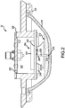
FIG. 2 illustrates an exterior lamp for an aircraft, in accordance with various embodiments. - All ranges and ratio limits disclosed herein may be combined. It is to be understood that unless specifically stated otherwise, references to "a," "an," and/or "the" may include one or more than one and that reference to an item in the singular may also include the item in the plural.
- The detailed description of exemplary embodiments herein makes reference to the accompanying drawings, which show exemplary embodiments by way of illustration. While these exemplary embodiments are described in sufficient detail to enable those skilled in the art to practice the exemplary embodiments of the disclosure, it should be understood that other embodiments may be realized and that logical changes and adaptations in design and construction may be made in accordance with this disclosure and the teachings herein. Thus, the detailed description herein is presented for purposes of illustration only and not limitation.
- The scope of the disclosure is defined by the appended claims and their legal equivalents rather than by merely the examples described. For example, the steps recited in any of the method or process descriptions may be executed in any order and are not necessarily limited to the order presented. Furthermore, any reference to singular includes plural embodiments, and any reference to more than one component or step may include a singular embodiment or step. Also, any reference to attached, fixed, coupled, connected or the like may include permanent, removable, temporary, partial, full and/or any other possible attachment option. Additionally, any reference to without contact (or similar phrases) may also include reduced contact or minimal contact. Surface shading lines may be used throughout the figures to denote different parts but not necessarily to denote the same or different materials.
- With reference to
FIG. 1 , anaircraft 10 is illustrated in accordance with various embodiments.Aircraft 10 comprises afuselage 12,wings 14,empennage 16,landing gear 18, a propulsion system, such asgas turbine engines 20, and a plurality ofexterior lights 22.Exterior lights 22 may include any number of lights know to those skilled in the art such as, for example, navigation lights, logo lights, wing scan lights, runway turnoff lights, cargo loading lights, engine scan lights, anti-collision strobe lights, beacon lights, and/or the like. It will be appreciated that the number and location of theexterior lights 22 are exemplary andaircraft 10 may include any number of additional lights which may be beneficial to operation ofaircraft 10 but are not illustrated. - With additional reference to
FIG. 2 , interior details ofexterior light 22 are illustrated in schematic cross section according to various embodiments.Exterior light 22 may comprise ahousing 200 defining aninterior volume 202.Exterior light 22 incudes alight source 216 configured to emit a light such as, for example, an array of light emitting diodes (LEDs). Aheat source 204 is disposed within theinterior volume 202 of thehousing 200. Acapillary transport apparatus 206 may be coupled to theheat source 204. Thecapillary transport apparatus 206 may be coupled to theheat source 204 at afirst end 208. Asecond end 210 of thecapillary transport apparatus 206 may extend into acatchment basin 212. Thecapillary transport apparatus 206 may be coupled by one of bonding, staking, pinning, or by afriction coupling 228 such as, for example, one of a clamp, a ferrule, a crimp, and/or the like. In various embodiments, thecatchment basin 212 may be defined by thehousing 200. In various embodiments and in response to changes in environmental conditions, acondensate 214 may form within theinterior volume 202 ofhousing 200 and tend to collect within thecatchment basin 212. In various embodiments, thecapillary transport apparatus 206 may comprise one of a wick, a woven material, a fibrous material, a braided material, or any other sort of material understood to promote capillary transportation of the condensate from thecatchment basin 212 toward theheat source 204. - In various embodiments, the
light source 216 may be protected by aprotective lens 218 configured to emit the light from thelight source 216. In various embodiments, the protective lens may be sealed to thehousing 200 such as, for example, by aseal ring 220. In various embodiments, theprotective lens 218 may define thecatchment basin 212. In various embodiments, theprotective lens 218 may enclose a reflector 222 configured to reflect the light from thelight source 216. The reflector 222 may have an annular structure and thesecond end 210 of thecapillary transport apparatus 206 may extend through an annulus of the reflector 222. In various embodiments, adriver board 224 may be configured to drive thelight source 216. Thedriver board 224 may comprise theheat source 204 and may be coupled to aheat sink 226 which may tend to receive thermal energy from theheat source 204. In various embodiments, thefirst end 208 of thecapillary transport apparatus 206 may be coupled to theheat sink 226. - In this regard, the
condensate 214 may tend to collect in thecatchment basin 212 and be wicked by thecapillary transport apparatus 206 from thecatchment basin 212 toward theheat source 204. Theheat source 204 may tend to evaporate thecondensate 214 to generate a vapor which may diffuse throughout theinterior volume 202 of thehousing 200. In various embodiments, thehousing 200 may comprise a vaporpermeable membrane 230 in fluid communication between theinterior volume 202 and the external environment (i.e., the exterior of the housing 200). In this regard, thehousing 200 includes a transport path for the vapor to diffuse from theinterior volume 202 of thehousing 200 and thereby exit thehousing 200. In various embodiments, theseal ring 220 may comprise a vapor permeable membrane. In this regard, the evaporated vapor may tend to diffuse through the vaporpermeable membrane 230 and thereby exit theexterior light 22. - Benefits and other advantages have been described herein with regard to specific embodiments. Furthermore, the connecting lines shown in the various figures contained herein are intended to represent exemplary functional relationships and/or physical couplings between the various elements. It should be noted that many alternative or additional functional relationships or physical connections may be present in a practical system. However, the benefits, advantages, and any elements that may cause any benefit or advantage to occur or become more pronounced are not to be construed as critical, required, or essential features or elements of the disclosure. The scope of the disclosure is accordingly to be limited by nothing other than the appended claims, in which reference to an element in the singular is not intended to mean "one and only one" unless explicitly so stated, but rather "one or more." Moreover, where a phrase similar to "at least one of A, B, or C" is used in the claims, it is intended that the phrase be interpreted to mean that A alone may be present in an embodiment, B alone may be present in an embodiment, C alone may be present in an embodiment, or that any combination of the elements A, B and C may be present in a single embodiment; for example, A and B, A and C, B and C, or A and B and C.
- Systems, methods and apparatus are provided herein. In the detailed description herein, references to "various embodiments," "one embodiment," "an embodiment," "an example embodiment," etc., indicate that the embodiment described may include a particular feature, structure, or characteristic, but every embodiment may not necessarily include the particular feature, structure, or characteristic. Moreover, such phrases are not necessarily referring to the same embodiment. Further, when a particular feature, structure, or characteristic is described in connection with an embodiment, it is submitted that it is within the knowledge of one skilled in the art to affect such feature, structure, or characteristic in connection with other embodiments whether or not explicitly described. After reading the description, it will be apparent to one skilled in the relevant art(s) how to implement the disclosure in alternative embodiments.
- Furthermore, no element, component, or method step in the present disclosure is intended to be dedicated to the public regardless of whether the element, component, or method step is explicitly recited in the claims. As used herein, the terms "comprises," "comprising," or any other variation thereof, are intended to cover a non-exclusive inclusion, such that a process, method, article, or apparatus that comprises a list of elements does not include only those elements but may include other elements not expressly listed or inherent to such process, method, article, or apparatus.
Claims (15)
- An article of manufacture, comprising:a housing (200) defining an interior volume;a heat source (204) disposed within the interior volume of the housing; anda capillary transport apparatus (206) having a first end and a second end,wherein the first end is coupled to the heat source and the second end is disposed in a catchment basin.
- The article of manufacture of claim 1, wherein the catchment basin is defined by the housing.
- The article of manufacture of claim 1 or 2, further comprising a light source disposed within the housing and configured to emit a light.
- The article of manufacture of claim 3, further comprising a protective lens configured to transmit the light from the light source.
- The article of manufacture of claim 4, wherein the catchment basin is defined by the protective lens.
- The article of manufacture of claim 4, wherein the heat source is a driver board configured to drive the light source.
- The article of manufacture of claim 6, wherein the first end is coupled to a heat sink of the driver board.
- The article of manufacture of claim 5, wherein the protective lens encloses a reflector, wherein the second end of the capillary transport apparatus extends through the reflector.
- The article of manufacture of any preceding claim, wherein the capillary transport apparatus is coupled to the heat source by bonding.
- The article of manufacture of any preceding claim, wherein the capillary transport apparatus is coupled to the heat source by a friction coupling, or wherein the capillary transport apparatus comprises one of a wick, a woven material, a fibrous material, or a braided material.
- The article of manufacture of any preceding claim, further comprising a vapor permeable membrane in fluid communication between the interior volume of the housing and an exterior of the housing.
- An exterior lamp for an aircraft, comprising:a housing (200) defining an interior volume;a heat source (204) disposed within the interior volume of the housing;a light source (216) disposed within the housing configured to emit a light therefrom;a protective lens (218) coupled to the housing proximate the light source, wherein the protective lens is configured to transmit the light; anda capillary transport apparatus (206) having a first end and a second end,wherein the first end is coupled to the heat source and the second end is disposed in a catchment basin.
- The exterior lamp of claim 12, wherein the catchment basin is defined by the protective lens.
- The exterior lamp of claim 13, wherein the heat source is a driver board configured to drive the light source, and optionally wherein the first end is coupled to a heat sink of the driver board, and optionally wherein the protective lens encloses a reflector, wherein the second end of the capillary transport apparatus extends through the reflector into the catchment basin, and optionally further comprising a vapor permeable membrane in fluid communication between the interior volume of the housing and an exterior of the housing, and optionally wherein the capillary transport apparatus comprises one of a wick, a woven material, a fibrous material, or a braided material.
- A method of mitigating condensation within a housing, comprising:collecting a condensate within a catchment basin;wicking the condensate from the catchment basin toward a heat source evaporating the condensate to generate a vapor; anddiffusing the vapor through a transport path in fluid communication with an interior volume of the housing.
Applications Claiming Priority (1)
| Application Number | Priority Date | Filing Date | Title |
|---|---|---|---|
| US16/746,464 US11104451B2 (en) | 2020-01-17 | 2020-01-17 | Systems and methods for mitigating condensation in aircraft lighting |
Publications (2)
| Publication Number | Publication Date |
|---|---|
| EP3851742A1 true EP3851742A1 (en) | 2021-07-21 |
| EP3851742B1 EP3851742B1 (en) | 2023-08-09 |
Family
ID=74184529
Family Applications (1)
| Application Number | Title | Priority Date | Filing Date |
|---|---|---|---|
| EP21151693.5A Active EP3851742B1 (en) | 2020-01-17 | 2021-01-14 | Systems and methods for mitigating condensation in aircraft lighting |
Country Status (2)
| Country | Link |
|---|---|
| US (1) | US11104451B2 (en) |
| EP (1) | EP3851742B1 (en) |
Cited By (1)
| Publication number | Priority date | Publication date | Assignee | Title |
|---|---|---|---|---|
| EP4461653A1 (en) * | 2023-05-11 | 2024-11-13 | Goodrich Lighting Systems GmbH & Co. KG | Exterior aircraft light, aircraft comprising an exterior aircraft light and method of draining a fluid out of an exterior aircraft light |
Families Citing this family (1)
| Publication number | Priority date | Publication date | Assignee | Title |
|---|---|---|---|---|
| US11320141B1 (en) | 2020-07-24 | 2022-05-03 | Michael Puckett | Hybrid light and fan fixture |
Citations (6)
| Publication number | Priority date | Publication date | Assignee | Title |
|---|---|---|---|---|
| KR20020083827A (en) * | 2001-04-30 | 2002-11-04 | 현대자동차주식회사 | Apparatus for cooling and removal of moisture of headlamp using heat pipe |
| EP2711625A1 (en) * | 2012-09-24 | 2014-03-26 | Scania CV AB | Light apparatus |
| US20170138584A1 (en) * | 2015-11-13 | 2017-05-18 | Goodrich Lighting Systems Gmbh | Exterior Aircraft Light Unit |
| US20170211795A1 (en) * | 2014-07-22 | 2017-07-27 | Philips Lighting Holding B.V. | Flexible coiled artery wick |
| WO2019022621A2 (en) * | 2017-07-28 | 2019-01-31 | Stuart Dundonald Reid | A desiccating pump |
| US20190078830A1 (en) * | 2015-09-24 | 2019-03-14 | Roche Diagnostics Operations, Inc. | Condensed water collector |
Family Cites Families (17)
| Publication number | Priority date | Publication date | Assignee | Title |
|---|---|---|---|---|
| FR2899955B1 (en) * | 2006-04-12 | 2009-11-20 | Osean | SUBAQUATIC ILLUMINATION DEVICE SUITABLE FOR USE IN A MARINE ENVIRONMENT |
| US20090101730A1 (en) * | 2007-10-19 | 2009-04-23 | Davis Brian T | Vented Dispensing Bottle/Cap Assembly |
| US8320751B2 (en) * | 2007-12-20 | 2012-11-27 | S.C. Johnson & Son, Inc. | Volatile material diffuser and method of preventing undesirable mixing of volatile materials |
| US20110193479A1 (en) * | 2010-02-08 | 2011-08-11 | Nilssen Ole K | Evaporation Cooled Lamp |
| TWI442527B (en) * | 2010-02-11 | 2014-06-21 | 寶福通光能有限公司 | Hardened modular semiconductor device |
| US20110253801A1 (en) * | 2010-04-16 | 2011-10-20 | Kristian Buschmann | Volatile Material Dispensers |
| GB201110696D0 (en) * | 2011-06-24 | 2011-08-10 | Reckitt & Colman Overseas | Devices and methods for emanating liquids |
| US20150144713A1 (en) * | 2011-11-09 | 2015-05-28 | Karen Formico | Repellant system and method |
| CN103174950A (en) * | 2011-12-20 | 2013-06-26 | 富准精密工业(深圳)有限公司 | Light-emitting diode bulb |
| CN103174960A (en) * | 2011-12-22 | 2013-06-26 | 富准精密工业(深圳)有限公司 | High-effect light-emitting diode bulb |
| US20130294070A1 (en) * | 2012-05-03 | 2013-11-07 | Chia-Tsung Tsao | High bay light |
| US20150338171A1 (en) * | 2012-12-28 | 2015-11-26 | Ibérica Del Espacio, S.A. | Loop heat pipe apparatus for heat transfer and thermal control |
| JP2015197392A (en) * | 2014-04-02 | 2015-11-09 | ホシデン株式会社 | Liquid presence / absence detection device having a power source and air improvement device having the same |
| US10652993B2 (en) * | 2015-07-20 | 2020-05-12 | Ii-Vi Delaware, Inc. | Thermoelectric device cooling system |
| WO2017037921A1 (en) * | 2015-09-03 | 2017-03-09 | 富士通株式会社 | Loop heat pipe, manufacturing method for same, and electronic device |
| US10208941B2 (en) * | 2015-11-19 | 2019-02-19 | Philips Lighting Holding B.V. | Lamp comprising cooling means |
| ES2887007T3 (en) * | 2018-09-21 | 2021-12-21 | Goodrich Lighting Systems Gmbh | Exterior light of aircraft and aircraft comprising the same |
-
2020
- 2020-01-17 US US16/746,464 patent/US11104451B2/en active Active
-
2021
- 2021-01-14 EP EP21151693.5A patent/EP3851742B1/en active Active
Patent Citations (6)
| Publication number | Priority date | Publication date | Assignee | Title |
|---|---|---|---|---|
| KR20020083827A (en) * | 2001-04-30 | 2002-11-04 | 현대자동차주식회사 | Apparatus for cooling and removal of moisture of headlamp using heat pipe |
| EP2711625A1 (en) * | 2012-09-24 | 2014-03-26 | Scania CV AB | Light apparatus |
| US20170211795A1 (en) * | 2014-07-22 | 2017-07-27 | Philips Lighting Holding B.V. | Flexible coiled artery wick |
| US20190078830A1 (en) * | 2015-09-24 | 2019-03-14 | Roche Diagnostics Operations, Inc. | Condensed water collector |
| US20170138584A1 (en) * | 2015-11-13 | 2017-05-18 | Goodrich Lighting Systems Gmbh | Exterior Aircraft Light Unit |
| WO2019022621A2 (en) * | 2017-07-28 | 2019-01-31 | Stuart Dundonald Reid | A desiccating pump |
Cited By (2)
| Publication number | Priority date | Publication date | Assignee | Title |
|---|---|---|---|---|
| EP4461653A1 (en) * | 2023-05-11 | 2024-11-13 | Goodrich Lighting Systems GmbH & Co. KG | Exterior aircraft light, aircraft comprising an exterior aircraft light and method of draining a fluid out of an exterior aircraft light |
| US12435857B2 (en) | 2023-05-11 | 2025-10-07 | Goodrich Lighting Systems GmbH & Co. KG | Exterior aircraft light, aircraft comprising an exterior aircraft light and method of draining a fluid out of an exterior aircraft light |
Also Published As
| Publication number | Publication date |
|---|---|
| US20210221533A1 (en) | 2021-07-22 |
| US11104451B2 (en) | 2021-08-31 |
| EP3851742B1 (en) | 2023-08-09 |
Similar Documents
| Publication | Publication Date | Title |
|---|---|---|
| EP3851742B1 (en) | Systems and methods for mitigating condensation in aircraft lighting | |
| US8627667B2 (en) | Gas turbine engine duct having a coupled fluid volume | |
| US10203079B2 (en) | Lighting apparatus with conversion device | |
| CA2742834C (en) | Integrated inlet design | |
| US8362507B2 (en) | Optic assembly utilizing quantum dots | |
| US10018055B2 (en) | Fan platform | |
| CN108087834B (en) | Multi-beam lamp | |
| US10246199B2 (en) | Lighting device for aircraft allowing the integration of additional functions at its center | |
| EP2202153A3 (en) | Monolithic structure for mounting aircraft engine | |
| CN108930824A (en) | Bleed valve, external aircraft light unit and power supply box | |
| CN102417029A (en) | Compression mounted window assembly | |
| US20120023967A1 (en) | Auxiliary power unit with hot section fire enclosure arrangement | |
| EP3670347A1 (en) | Anti-ice double walled duct system | |
| EP3321183A1 (en) | External aircraft emergency lighting | |
| US10815004B2 (en) | Lens structure for a light unit, light unit, and aircraft comprising such light unit | |
| EP3812286B1 (en) | Anti-collision light assembly | |
| US20210332762A1 (en) | Improved air-sealing device intended to be inserted between an aircraft dual-flow turbine engine casing element, and a nacelle element | |
| GB2540264A (en) | Navigation lights | |
| CN110094662A (en) | Light directing assembly and method for providing a light directing assembly for a tower | |
| EP3835560B1 (en) | Lidar based fod detection for gas-turbine engines | |
| US4850337A (en) | Solar energy apparatus with apertured shield | |
| EP3590841A1 (en) | Inlet - nai exhaust hole definition for reduced d-duct resonance noise and diluted exhaust plume for thermal control | |
| US10894614B1 (en) | Halo light assembly | |
| US3935704A (en) | Fan propulsor oil escapement means | |
| CN214535859U (en) | Aircraft detection lamp with complex light-emitting angle and efficient heat dissipation |
Legal Events
| Date | Code | Title | Description |
|---|---|---|---|
| PUAI | Public reference made under article 153(3) epc to a published international application that has entered the european phase |
Free format text: ORIGINAL CODE: 0009012 |
|
| STAA | Information on the status of an ep patent application or granted ep patent |
Free format text: STATUS: THE APPLICATION HAS BEEN PUBLISHED |
|
| AK | Designated contracting states |
Kind code of ref document: A1 Designated state(s): AL AT BE BG CH CY CZ DE DK EE ES FI FR GB GR HR HU IE IS IT LI LT LU LV MC MK MT NL NO PL PT RO RS SE SI SK SM TR |
|
| STAA | Information on the status of an ep patent application or granted ep patent |
Free format text: STATUS: REQUEST FOR EXAMINATION WAS MADE |
|
| 17P | Request for examination filed |
Effective date: 20220121 |
|
| RBV | Designated contracting states (corrected) |
Designated state(s): AL AT BE BG CH CY CZ DE DK EE ES FI FR GB GR HR HU IE IS IT LI LT LU LV MC MK MT NL NO PL PT RO RS SE SI SK SM TR |
|
| GRAP | Despatch of communication of intention to grant a patent |
Free format text: ORIGINAL CODE: EPIDOSNIGR1 |
|
| STAA | Information on the status of an ep patent application or granted ep patent |
Free format text: STATUS: GRANT OF PATENT IS INTENDED |
|
| RIC1 | Information provided on ipc code assigned before grant |
Ipc: F21Y 115/10 20160101ALN20230130BHEP Ipc: F21W 107/30 20180101ALN20230130BHEP Ipc: F21V 31/03 20060101ALN20230130BHEP Ipc: F21V 23/00 20060101ALN20230130BHEP Ipc: F21V 29/51 20150101ALI20230130BHEP Ipc: B64D 47/02 20060101ALI20230130BHEP Ipc: F21V 29/508 20150101AFI20230130BHEP |
|
| INTG | Intention to grant announced |
Effective date: 20230227 |
|
| GRAS | Grant fee paid |
Free format text: ORIGINAL CODE: EPIDOSNIGR3 |
|
| GRAA | (expected) grant |
Free format text: ORIGINAL CODE: 0009210 |
|
| STAA | Information on the status of an ep patent application or granted ep patent |
Free format text: STATUS: THE PATENT HAS BEEN GRANTED |
|
| AK | Designated contracting states |
Kind code of ref document: B1 Designated state(s): AL AT BE BG CH CY CZ DE DK EE ES FI FR GB GR HR HU IE IS IT LI LT LU LV MC MK MT NL NO PL PT RO RS SE SI SK SM TR |
|
| REG | Reference to a national code |
Ref country code: GB Ref legal event code: FG4D |
|
| REG | Reference to a national code |
Ref country code: CH Ref legal event code: EP |
|
| REG | Reference to a national code |
Ref country code: DE Ref legal event code: R096 Ref document number: 602021004033 Country of ref document: DE |
|
| REG | Reference to a national code |
Ref country code: IE Ref legal event code: FG4D |
|
| P01 | Opt-out of the competence of the unified patent court (upc) registered |
Effective date: 20230922 |
|
| REG | Reference to a national code |
Ref country code: LT Ref legal event code: MG9D |
|
| REG | Reference to a national code |
Ref country code: NL Ref legal event code: MP Effective date: 20230809 |
|
| REG | Reference to a national code |
Ref country code: AT Ref legal event code: MK05 Ref document number: 1597920 Country of ref document: AT Kind code of ref document: T Effective date: 20230809 |
|
| PG25 | Lapsed in a contracting state [announced via postgrant information from national office to epo] |
Ref country code: GR Free format text: LAPSE BECAUSE OF FAILURE TO SUBMIT A TRANSLATION OF THE DESCRIPTION OR TO PAY THE FEE WITHIN THE PRESCRIBED TIME-LIMIT Effective date: 20231110 |
|
| PG25 | Lapsed in a contracting state [announced via postgrant information from national office to epo] |
Ref country code: IS Free format text: LAPSE BECAUSE OF FAILURE TO SUBMIT A TRANSLATION OF THE DESCRIPTION OR TO PAY THE FEE WITHIN THE PRESCRIBED TIME-LIMIT Effective date: 20231209 |
|
| PG25 | Lapsed in a contracting state [announced via postgrant information from national office to epo] |
Ref country code: SE Free format text: LAPSE BECAUSE OF FAILURE TO SUBMIT A TRANSLATION OF THE DESCRIPTION OR TO PAY THE FEE WITHIN THE PRESCRIBED TIME-LIMIT Effective date: 20230809 Ref country code: RS Free format text: LAPSE BECAUSE OF FAILURE TO SUBMIT A TRANSLATION OF THE DESCRIPTION OR TO PAY THE FEE WITHIN THE PRESCRIBED TIME-LIMIT Effective date: 20230809 Ref country code: PT Free format text: LAPSE BECAUSE OF FAILURE TO SUBMIT A TRANSLATION OF THE DESCRIPTION OR TO PAY THE FEE WITHIN THE PRESCRIBED TIME-LIMIT Effective date: 20231211 Ref country code: NO Free format text: LAPSE BECAUSE OF FAILURE TO SUBMIT A TRANSLATION OF THE DESCRIPTION OR TO PAY THE FEE WITHIN THE PRESCRIBED TIME-LIMIT Effective date: 20231109 Ref country code: NL Free format text: LAPSE BECAUSE OF FAILURE TO SUBMIT A TRANSLATION OF THE DESCRIPTION OR TO PAY THE FEE WITHIN THE PRESCRIBED TIME-LIMIT Effective date: 20230809 Ref country code: LV Free format text: LAPSE BECAUSE OF FAILURE TO SUBMIT A TRANSLATION OF THE DESCRIPTION OR TO PAY THE FEE WITHIN THE PRESCRIBED TIME-LIMIT Effective date: 20230809 Ref country code: LT Free format text: LAPSE BECAUSE OF FAILURE TO SUBMIT A TRANSLATION OF THE DESCRIPTION OR TO PAY THE FEE WITHIN THE PRESCRIBED TIME-LIMIT Effective date: 20230809 Ref country code: IS Free format text: LAPSE BECAUSE OF FAILURE TO SUBMIT A TRANSLATION OF THE DESCRIPTION OR TO PAY THE FEE WITHIN THE PRESCRIBED TIME-LIMIT Effective date: 20231209 Ref country code: HR Free format text: LAPSE BECAUSE OF FAILURE TO SUBMIT A TRANSLATION OF THE DESCRIPTION OR TO PAY THE FEE WITHIN THE PRESCRIBED TIME-LIMIT Effective date: 20230809 Ref country code: GR Free format text: LAPSE BECAUSE OF FAILURE TO SUBMIT A TRANSLATION OF THE DESCRIPTION OR TO PAY THE FEE WITHIN THE PRESCRIBED TIME-LIMIT Effective date: 20231110 Ref country code: FI Free format text: LAPSE BECAUSE OF FAILURE TO SUBMIT A TRANSLATION OF THE DESCRIPTION OR TO PAY THE FEE WITHIN THE PRESCRIBED TIME-LIMIT Effective date: 20230809 Ref country code: AT Free format text: LAPSE BECAUSE OF FAILURE TO SUBMIT A TRANSLATION OF THE DESCRIPTION OR TO PAY THE FEE WITHIN THE PRESCRIBED TIME-LIMIT Effective date: 20230809 |
|
| PG25 | Lapsed in a contracting state [announced via postgrant information from national office to epo] |
Ref country code: PL Free format text: LAPSE BECAUSE OF FAILURE TO SUBMIT A TRANSLATION OF THE DESCRIPTION OR TO PAY THE FEE WITHIN THE PRESCRIBED TIME-LIMIT Effective date: 20230809 |
|
| PG25 | Lapsed in a contracting state [announced via postgrant information from national office to epo] |
Ref country code: ES Free format text: LAPSE BECAUSE OF FAILURE TO SUBMIT A TRANSLATION OF THE DESCRIPTION OR TO PAY THE FEE WITHIN THE PRESCRIBED TIME-LIMIT Effective date: 20230809 |
|
| PG25 | Lapsed in a contracting state [announced via postgrant information from national office to epo] |
Ref country code: SM Free format text: LAPSE BECAUSE OF FAILURE TO SUBMIT A TRANSLATION OF THE DESCRIPTION OR TO PAY THE FEE WITHIN THE PRESCRIBED TIME-LIMIT Effective date: 20230809 Ref country code: RO Free format text: LAPSE BECAUSE OF FAILURE TO SUBMIT A TRANSLATION OF THE DESCRIPTION OR TO PAY THE FEE WITHIN THE PRESCRIBED TIME-LIMIT Effective date: 20230809 Ref country code: ES Free format text: LAPSE BECAUSE OF FAILURE TO SUBMIT A TRANSLATION OF THE DESCRIPTION OR TO PAY THE FEE WITHIN THE PRESCRIBED TIME-LIMIT Effective date: 20230809 Ref country code: EE Free format text: LAPSE BECAUSE OF FAILURE TO SUBMIT A TRANSLATION OF THE DESCRIPTION OR TO PAY THE FEE WITHIN THE PRESCRIBED TIME-LIMIT Effective date: 20230809 Ref country code: DK Free format text: LAPSE BECAUSE OF FAILURE TO SUBMIT A TRANSLATION OF THE DESCRIPTION OR TO PAY THE FEE WITHIN THE PRESCRIBED TIME-LIMIT Effective date: 20230809 Ref country code: CZ Free format text: LAPSE BECAUSE OF FAILURE TO SUBMIT A TRANSLATION OF THE DESCRIPTION OR TO PAY THE FEE WITHIN THE PRESCRIBED TIME-LIMIT Effective date: 20230809 Ref country code: SK Free format text: LAPSE BECAUSE OF FAILURE TO SUBMIT A TRANSLATION OF THE DESCRIPTION OR TO PAY THE FEE WITHIN THE PRESCRIBED TIME-LIMIT Effective date: 20230809 |
|
| REG | Reference to a national code |
Ref country code: DE Ref legal event code: R097 Ref document number: 602021004033 Country of ref document: DE |
|
| PG25 | Lapsed in a contracting state [announced via postgrant information from national office to epo] |
Ref country code: IT Free format text: LAPSE BECAUSE OF FAILURE TO SUBMIT A TRANSLATION OF THE DESCRIPTION OR TO PAY THE FEE WITHIN THE PRESCRIBED TIME-LIMIT Effective date: 20230809 |
|
| PLBE | No opposition filed within time limit |
Free format text: ORIGINAL CODE: 0009261 |
|
| STAA | Information on the status of an ep patent application or granted ep patent |
Free format text: STATUS: NO OPPOSITION FILED WITHIN TIME LIMIT |
|
| 26N | No opposition filed |
Effective date: 20240513 |
|
| PG25 | Lapsed in a contracting state [announced via postgrant information from national office to epo] |
Ref country code: SI Free format text: LAPSE BECAUSE OF FAILURE TO SUBMIT A TRANSLATION OF THE DESCRIPTION OR TO PAY THE FEE WITHIN THE PRESCRIBED TIME-LIMIT Effective date: 20230809 |
|
| PG25 | Lapsed in a contracting state [announced via postgrant information from national office to epo] |
Ref country code: MC Free format text: LAPSE BECAUSE OF FAILURE TO SUBMIT A TRANSLATION OF THE DESCRIPTION OR TO PAY THE FEE WITHIN THE PRESCRIBED TIME-LIMIT Effective date: 20230809 |
|
| PG25 | Lapsed in a contracting state [announced via postgrant information from national office to epo] |
Ref country code: MC Free format text: LAPSE BECAUSE OF FAILURE TO SUBMIT A TRANSLATION OF THE DESCRIPTION OR TO PAY THE FEE WITHIN THE PRESCRIBED TIME-LIMIT Effective date: 20230809 |
|
| REG | Reference to a national code |
Ref country code: CH Ref legal event code: PL |
|
| PG25 | Lapsed in a contracting state [announced via postgrant information from national office to epo] |
Ref country code: LU Free format text: LAPSE BECAUSE OF NON-PAYMENT OF DUE FEES Effective date: 20240114 |
|
| PG25 | Lapsed in a contracting state [announced via postgrant information from national office to epo] |
Ref country code: LU Free format text: LAPSE BECAUSE OF NON-PAYMENT OF DUE FEES Effective date: 20240114 |
|
| PG25 | Lapsed in a contracting state [announced via postgrant information from national office to epo] |
Ref country code: BE Free format text: LAPSE BECAUSE OF NON-PAYMENT OF DUE FEES Effective date: 20240131 |
|
| PG25 | Lapsed in a contracting state [announced via postgrant information from national office to epo] |
Ref country code: CH Free format text: LAPSE BECAUSE OF NON-PAYMENT OF DUE FEES Effective date: 20240131 |
|
| PG25 | Lapsed in a contracting state [announced via postgrant information from national office to epo] |
Ref country code: CH Free format text: LAPSE BECAUSE OF NON-PAYMENT OF DUE FEES Effective date: 20240131 Ref country code: BE Free format text: LAPSE BECAUSE OF NON-PAYMENT OF DUE FEES Effective date: 20240131 |
|
| REG | Reference to a national code |
Ref country code: BE Ref legal event code: MM Effective date: 20240131 |
|
| PG25 | Lapsed in a contracting state [announced via postgrant information from national office to epo] |
Ref country code: BG Free format text: LAPSE BECAUSE OF FAILURE TO SUBMIT A TRANSLATION OF THE DESCRIPTION OR TO PAY THE FEE WITHIN THE PRESCRIBED TIME-LIMIT Effective date: 20230809 |
|
| PG25 | Lapsed in a contracting state [announced via postgrant information from national office to epo] |
Ref country code: BG Free format text: LAPSE BECAUSE OF FAILURE TO SUBMIT A TRANSLATION OF THE DESCRIPTION OR TO PAY THE FEE WITHIN THE PRESCRIBED TIME-LIMIT Effective date: 20230809 |
|
| PG25 | Lapsed in a contracting state [announced via postgrant information from national office to epo] |
Ref country code: IE Free format text: LAPSE BECAUSE OF NON-PAYMENT OF DUE FEES Effective date: 20240114 |
|
| PG25 | Lapsed in a contracting state [announced via postgrant information from national office to epo] |
Ref country code: IE Free format text: LAPSE BECAUSE OF NON-PAYMENT OF DUE FEES Effective date: 20240114 |
|
| PG25 | Lapsed in a contracting state [announced via postgrant information from national office to epo] |
Ref country code: CY Free format text: LAPSE BECAUSE OF FAILURE TO SUBMIT A TRANSLATION OF THE DESCRIPTION OR TO PAY THE FEE WITHIN THE PRESCRIBED TIME-LIMIT; INVALID AB INITIO Effective date: 20210114 |
|
| PG25 | Lapsed in a contracting state [announced via postgrant information from national office to epo] |
Ref country code: HU Free format text: LAPSE BECAUSE OF FAILURE TO SUBMIT A TRANSLATION OF THE DESCRIPTION OR TO PAY THE FEE WITHIN THE PRESCRIBED TIME-LIMIT; INVALID AB INITIO Effective date: 20210114 |
|
| PG25 | Lapsed in a contracting state [announced via postgrant information from national office to epo] |
Ref country code: TR Free format text: LAPSE BECAUSE OF FAILURE TO SUBMIT A TRANSLATION OF THE DESCRIPTION OR TO PAY THE FEE WITHIN THE PRESCRIBED TIME-LIMIT Effective date: 20230809 |
|
| PGFP | Annual fee paid to national office [announced via postgrant information from national office to epo] |
Ref country code: GB Payment date: 20251220 Year of fee payment: 6 |
|
| PGFP | Annual fee paid to national office [announced via postgrant information from national office to epo] |
Ref country code: FR Payment date: 20251218 Year of fee payment: 6 |
|
| PGFP | Annual fee paid to national office [announced via postgrant information from national office to epo] |
Ref country code: DE Payment date: 20251217 Year of fee payment: 6 |