EP3851682A1 - Centrifugal compressor and diffuser device - Google Patents
Centrifugal compressor and diffuser device Download PDFInfo
- Publication number
- EP3851682A1 EP3851682A1 EP19900666.9A EP19900666A EP3851682A1 EP 3851682 A1 EP3851682 A1 EP 3851682A1 EP 19900666 A EP19900666 A EP 19900666A EP 3851682 A1 EP3851682 A1 EP 3851682A1
- Authority
- EP
- European Patent Office
- Prior art keywords
- diffuser part
- diffuser
- pressure
- piston
- movable
- Prior art date
- Legal status (The legal status is an assumption and is not a legal conclusion. Google has not performed a legal analysis and makes no representation as to the accuracy of the status listed.)
- Granted
Links
Images


Classifications
-
- F—MECHANICAL ENGINEERING; LIGHTING; HEATING; WEAPONS; BLASTING
- F04—POSITIVE - DISPLACEMENT MACHINES FOR LIQUIDS; PUMPS FOR LIQUIDS OR ELASTIC FLUIDS
- F04D—NON-POSITIVE-DISPLACEMENT PUMPS
- F04D29/00—Details, component parts, or accessories
- F04D29/40—Casings; Connections of working fluid
- F04D29/42—Casings; Connections of working fluid for radial or helico-centrifugal pumps
- F04D29/44—Fluid-guiding means, e.g. diffusers
- F04D29/46—Fluid-guiding means, e.g. diffusers adjustable
- F04D29/462—Fluid-guiding means, e.g. diffusers adjustable especially adapted for elastic fluid pumps
- F04D29/464—Fluid-guiding means, e.g. diffusers adjustable especially adapted for elastic fluid pumps adjusting flow cross-section, otherwise than by using adjustable stator blades
-
- F—MECHANICAL ENGINEERING; LIGHTING; HEATING; WEAPONS; BLASTING
- F04—POSITIVE - DISPLACEMENT MACHINES FOR LIQUIDS; PUMPS FOR LIQUIDS OR ELASTIC FLUIDS
- F04D—NON-POSITIVE-DISPLACEMENT PUMPS
- F04D17/00—Radial-flow pumps, e.g. centrifugal pumps; Helico-centrifugal pumps
- F04D17/08—Centrifugal pumps
- F04D17/10—Centrifugal pumps for compressing or evacuating
-
- F—MECHANICAL ENGINEERING; LIGHTING; HEATING; WEAPONS; BLASTING
- F05—INDEXING SCHEMES RELATING TO ENGINES OR PUMPS IN VARIOUS SUBCLASSES OF CLASSES F01-F04
- F05D—INDEXING SCHEME FOR ASPECTS RELATING TO NON-POSITIVE-DISPLACEMENT MACHINES OR ENGINES, GAS-TURBINES OR JET-PROPULSION PLANTS
- F05D2250/00—Geometry
- F05D2250/50—Inlet or outlet
- F05D2250/52—Outlet
-
- F—MECHANICAL ENGINEERING; LIGHTING; HEATING; WEAPONS; BLASTING
- F05—INDEXING SCHEMES RELATING TO ENGINES OR PUMPS IN VARIOUS SUBCLASSES OF CLASSES F01-F04
- F05D—INDEXING SCHEME FOR ASPECTS RELATING TO NON-POSITIVE-DISPLACEMENT MACHINES OR ENGINES, GAS-TURBINES OR JET-PROPULSION PLANTS
- F05D2250/00—Geometry
- F05D2250/90—Variable geometry
Definitions
- the disclosure relates to the technical field of compressors, in particular to a centrifugal compressor and a diffuser.
- An air pressure in a centrifugal compressor is increased by rotation of an impeller and pressure diffusion of a diffuser.
- a centrifugal compressor a high-speed rotating impeller applies a centrifugal force to air, and also realizes pressure diffusion of the air in a pressure diffusion channel, and thus a pressure of the air is increased.
- a system For a centrifugal compressor capable of working under dual conditions, a system requires a proper cooling capacity under both a refrigerating condition and a heating condition.
- the cooling capacities under the two working conditions has little difference, for example, the cooling capacity required under a heating condition is a little larger than that required under a refrigerating condition. Therefore, the two working conditions can share the same dynamic design.
- the cooling capacity required under a heating condition is far lower than that required under a refrigerating condition, and accordingly the same aerodynamic design cannot simultaneously meet the requirements of the optimal cooling capacity range for the two working conditions. As a result, adverse phenomena such as gas flow stall and surging occur easily.
- an adjustable diffuser is arranged at an outlet of an impeller.
- the adjustable diffuser is driven to move to change the width of a diffuser flow channel.
- the adjustable diffuser is generally annular and is driven by a plurality of cam guide rod mechanisms.
- An embodiment of the present disclosure provides a centrifugal compressor and a diffuser, which can guarantee reliable running of a movable diffuser part.
- the movable diffuser part is moved to adjust the width of the pressure diffusion flow channel.
- a proper cooling capacity is provided under both a refrigerating condition and a heating condition to prevent adverse phenomena such as gas flow stall and surging.
- the pressure drive mechanism applies a thrust to the movable diffuser part through a pressure medium.
- a positive pressure perpendicular to the surface of the movable diffuser part can be applied to the movable diffuser part by the pressure medium.
- the annular movable diffuser part can be accurately pushed to move in the axial direction of the pressure medium.
- the movable diffuser part is prevented from inclination and chucking caused by a thrust inclined relative to an axis, and the reliability and stability of movement of the movable diffuser part are improved.
- the plurality of pressure drive mechanisms can be connected mutually, pressure mediums in the plurality of pressure drive mechanisms communicate with each other, and the flowing pressure mediums drive the plurality of pressure drive mechanisms to move synchronously.
- the movable diffuser part is synchronously driven at a plurality of points to move, only moves in the axial direction and remains the same position in other directions.
- the movable diffuser part can move smoothly to further guarantee the reliability of movement, and in this way the reliability of running of the centrifugal compressor is guaranteed.
- the diffuser further includes connecting pipes; the movable diffuser part is annular; and there are a plurality of pressure drive mechanisms.
- the plurality of pressure drive mechanisms are spaced in a circumferential direction of the movable diffuser part and are all connected with the movable diffuser part. All the pressure drive mechanisms are connected in series or in parallel through connecting pipes.
- the surface, facing toward the second diffuser part, of the first diffuser part is provided with a groove; the groove communicates with the pressure diffusion flow channel; and the movable diffuser part can be movably arranged in the groove.
- the movable diffuser part includes a first inclined surface facing toward the second diffuser part, and the first inclined surface is inclined to get close to the second diffuser part along the flowing direction of a gas flow in the pressure diffusion flow channel.
- the surface, facing toward the second diffuser part, of the first diffuser part includes a second inclined surface; and the second inclined surface is inclined to get close to the second diffuser part along the flowing direction of a gas flow in the pressure diffusion flow channel.
- the first inclined surface and the second inclined surface extend obliquely in the same direction, and the movable diffuser part is configured to make the first inclined surface be flush with the second inclined surface after moving to an extreme position close to the bottom surface of the groove.
- the pressure drive mechanism includes a cylinder and a piston, wherein the cylinder has an accommodating cavity; one end of the piston is slidably arranged in the accommodating cavity; the other end of the piston extends out of the cylinder and is connected with the movable diffuser part; and the piston is driven to slide by changing the volume of the pressure medium in the accommodating cavity.
- the pressure drive mechanism further includes an elastic member; the piston divides the accommodating cavity into a first cavity and a second cavity; the first cavity allows the pressure medium to flow in or out; the elastic member is accommodated in the second cavity; and the elastic member abuts between the piston and the inner wall of the second cavity along the moving direction of the piston.
- the piston includes a plug body and a rod body; the plug body is slidably arranged in the accommodating cavity along an axial direction; the rod body is connected to an axial side of the piston body, extends out of the cylinder via the second cavity and is connected with the movable diffuser part; the elastic member sleeves the outside of the rod body; and the two ends of the elastic member respectively abut against the plug body and the inner wall of the second cavity.
- the pressure drive mechanism further includes an inlet electromagnetic valve and an outlet electromagnetic valve; the first cavity is provided with a medium inlet and a medium outlet; the inlet electromagnetic valve is arranged at the medium inlet and configured to control the connection or disconnection of inflowing pressure medium; and the outlet electromagnetic valve is arranged at the medium outlet and configured to control the connection or disconnection of outflowing pressure medium.
- the surface, facing toward the second diffuser part, of the first diffuser part is provided with a groove, the groove communicates with the pressure diffusion flow channel, and the movable diffuser part is movably arranged in the groove; and the movable diffuser part is configured to form a preset gap with the bottom surface of the groove after moving to an extreme position close to the bottom surface of the groove.
- the pressure drive mechanism includes a cylinder, a piston and a cover, wherein the cylinder has an accommodating cavity; one end of the piston is slidably arranged in the accommodating cavity; the other end of the piston extends out of the cylinder and is connected with the movable diffuser part; and the cover seals the accommodating cavity; an end face, toward the cover, of the piston is provided with a first lug boss; an end face, facing toward the piston, of the cover is provided with a second lug boss; the movable diffuser part is configured to form the preset gap between the movable diffuser part and the bottom surface of the groove when the first lug boss abuts against the second lug boss.
- Another aspect of the embodiment of the present disclosure further provides a centrifugal compressor including an impeller and the above diffuser, wherein a pressure diffusion flow channel communicates with an outlet of the impeller.
- a diffuser 100 is provided.
- the diffuser 100 is arranged at an outlet of an impeller 210 in a centrifugal compressor and is configured to increase the airflow pressure.
- a width of a pressure diffusion flow channel 20 in the diffuser 100 is adjustable, thus a cooling capacity of the centrifugal compressor during running is adjusted. In this way, so that the centrifugal compressor can provide a proper cooling capacity under both a refrigerating condition and a heating condition.
- the diffuser 100 includes a pressure drive mechanism 10, a first diffuser part 32, a second diffuser part 34 and a movable diffuser part 50; the first diffuser part 32 and the second diffuser part 34 are oppositely spaced in an axial direction of the centrifugal compressor; a pressure diffusion flow channel 20 communicating with the outlet of the impeller 210 is formed between the first diffuser part 32 and the second diffuser part 34; and a gas flow flowing out of the impeller 210 is pressurized in the pressure diffusion flow channel 20.
- the movable diffuser part 50 is connected with the pressure drive mechanism 10 and is movably arranged on one of the first diffuser part 32 and the second diffuser part 34 and can get close to or leave away from the other one of the first diffuser part 32 and the second diffuser part 34 under the action of a pressure medium in the pressure drive mechanism 10 so as to adjust an width of the pressure diffusion flow channel 20.
- a proper cooling capacity can be provided under both a refrigerating condition and a heating condition to prevent adverse phenomena such as gas flow stall and surging.
- the pressure drive mechanism 10 applies a thrust to the movable diffuser part 50 through a pressure medium.
- a pressure of a fluid is determined according to a cooling capacity of a compressor.
- the pressure medium can generate a positive pressure to the movable diffuser part 50, and the positive pressure is perpendicular to the surface of the movable diffuser part 50.
- the annular movable diffuser part 50 can be pushed to move in the axial direction.
- the movable diffuser part 50 can be prevented from being inclined and chucked due to a thrust inclined relative to an axis. The reliability and stability of movement of the movable diffuser part 50 are improved.
- an annular movable diffuser part 50 when an annular movable diffuser part 50 is driven by a plurality of pressure drive mechanisms 10 spaced in a circumferential direction, the plurality of pressure drive mechanisms 10 can be connected mutually, pressure mediums in the plurality of pressure drive mechanisms 10 communicate with each other, and the flowing pressure mediums drive the plurality of pressure drive mechanisms 10 to move synchronously.
- the movable diffuser part 50 is synchronously driven at a plurality of points to move in only the axial direction and remains the same position in other directions, so that the movable diffuser part 50 smoothly moves. Therefore, the reliability of movement of the movable diffuser part 50 is further guaranteed, and thus the reliability of running of the centrifugal compressor is guaranteed.
- the way of adopting a pressure drive mechanism 10 to drive the movable diffuser part 50 can simplify a drive structure, the structure is compact, and space usage is reduced.
- the movable diffuser part 50 is arranged on the first diffuser part 32, and is movably arranged in a direction close to and away from the second diffuser part 34 under the driving of the pressure drive mechanism 10 so as to adjust a width of the pressure diffusion flow channel 20.
- the pressure drive mechanism 10 includes a cylinder 12 and a piston 14, wherein the cylinder 12 is provided with an accommodating cavity 11; one end of the piston 14 is slidably arranged in the accommodating cavity 11; the other end of the piston 14 extends out of the cylinder 12 and is connected with the movable diffuser part 50; and the piston 14 is driven to slide by changing the volume of a pressure medium in the accommodating cavity 11, and in this way the movable diffuser part 50 is driven to move.
- the piston 14 in the accommodating cavity 11 is driven to move by inflowing and outflowing of a pressure medium in the accommodating cavity 11.
- the piston 14 drives the movable diffuser part 50 to move and is applied with a pressure perpendicular to the surface of the piston 14, so that the piston 14 can slide smoothly, and the accuracy and reliability of running of the piston 14 and the movable diffuser part 50 are guaranteed.
- the pressure drive mechanism 10 further includes an elastic member 16; the piston 14 divides the accommodating cavity 11 into a first cavity 112 and a second cavity 114; the first cavity 112 allows a pressure medium to flow in or out; the elastic member 16 is accommodated in the second cavity 114; and the elastic member 16 abuts between the piston 14 and the inner wall of the second cavity 114 along the moving direction of the piston 14.
- the volume of the first cavity 112 is increased under the action of the pressure medium; meanwhile, the piston 14 moves to one side of the second cavity 114; the volume of the second cavity 14 is compressed; and simultaneously, the elastic member 16, located in a moving route of the piston 14, in the second cavity 114 is compressed as well.
- the piston 14 includes a plug body 141 and a rod body 143; the plug body 141 can be slidably arranged in the accommodating cavity 11; the rod body 143 is connected to one side of the plug body 141, extends out of the cylinder 12 via the second cavity 14 and is connected with the movable diffuser part 50, so that the movable diffuser part 50 is driven to move by the rod body 143; in addition, the rod body 143 is externally sleeved with the elastic member 16; the two ends of the elastic member 16 respectively abut against the plug body 141 and the inner wall of the second cavity 114; and meanwhile the elastic member 16 is installed by virtue of the rod body 143.
- the end face, facing toward the second cavity 114, of the plug body 141 is provided with an annular groove; the two ends of the elastic member 16 respectively abut against the bottom surface of the annular groove and the inner wall, away from the plug body 141, of the second cavity 114 in the axial direction.
- a sealing part may be arranged between the plug body 141 and the inner wall of the accommodating cavity 11; the sealing part is configured to seal the plug body 141 to prevent a pressure medium in the first cavity 112 and on one side of the plug body 141 from flowing into the second cavity 114 and being mixed with a refrigerant after entering the pressure diffusion flow channel 20, and thus influences on normal work of the refrigerant are avoided.
- the pressure drive mechanism 10 further includes an inlet electromagnetic valve 17 and an outlet electromagnetic valve 18; the first cavity 112 is provided with a medium inlet and a medium outlet; the inlet electromagnetic valve 17 is arranged at the medium inlet and configured to control the connection or disconnection of inflowing pressure medium; and the outlet electromagnetic valve 18 is arranged at the medium outlet and configured to control the connection or disconnection of outflowing pressure medium.
- the pressure medium is flexibly controlled to flow in or flow out by powering on or powering off the inlet electromagnetic valve 17 and the outlet electromagnetic valve 18.
- the movable diffuser part 50 is annular; there are a plurality of pressure drive mechanisms 10; the plurality of pressure drive mechanisms 10 are spaced in a circumferential direction of the movable diffuser part 50 and are all connected with the movable diffuser part 50; moreover, the pressure drive mechanisms 10 are connected in series or in parallel through connecting pipes so as to synchronously drive the movable diffuser part 50 to move from a plurality of points; and thus a stable and reliable driving process is achieved.
- the surface, facing toward the second diffuser part 34, of the first diffuser part 32 is provided with a groove 33; the groove 33 communicates with the pressure diffusion flow channel 20; the movable diffuser part 50 is movably arranged in the groove 33 and is accommodated in the groove 33.
- the groove 33 is configured in a ring shape and is matched with the movable diffuser part 50 in shape.
- the movable diffuser part 50 includes a first inclined surface 52 facing toward the second diffuser part 34, and the first inclined surface 52 is inclined to get close to the second diffuser part 34 along the flowing direction of a gas flow in the pressure diffusion flow channel 20, thereby forming a flow channel with a gradually-minimized section in the flowing direction of the gas flow, gathering a gas which is discharged from the impeller 210 and realizing pressure diffusion of the gas.
- the surface, facing toward the second diffuser part 34, of the first diffuser part 32 includes a second inclined surface 31; and the second inclined surface 31 is inclined to get close to the second diffuser part 34 along the flowing direction of a gas flow in the pressure diffusion flow channel 20, thereby further forming a flow channel with a gradually-reduced section in the flowing direction of the gas flow and further increasing the pressure of the gas.
- the first inclined surface 52 is flush with the second inclined surface 31 based on a maximum cooling capacity of the compressor; and the first inclined surface 52 and the second inclined surface 31 obliquely extend in the same direction, so that the first inclined surface 52 and the second inclined surface 31 are smoothly butted in a transition manner to realize smooth pressure diffusion.
- a gap is formed between the movable diffuser part 50 and the bottom surface of the groove 33 when the movable diffuser part 50 moves to an extreme position close to the bottom surface of the groove 33.
- the end face, away from the second diffuser part 34, of the cylinder 12 is provided with a cover 35; the cover 35 is configured to seal the first cavity 112; the end face, facing toward the cover 35, of the piston 14 is provided with a first lug boss 144; the end face, facing toward the piston 14, of the cover 35 is provided with a second lug boss 351; and the movable diffuser part 50 moves to an extreme position close to the bottom surface of the groove 33 when the piston 14 moves toward the cover 35 until the first lug boss 144 abuts against the second lug boss 351.
- a centrifugal compressor is further provided and includes the diffuser 100 of the above embodiments.
- the movable diffuser part 50 is arranged at the outlet of the impeller 210 of the centrifugal compressor, and a width of the pressure diffusion flow channel 20 is adjusted according to working conditions.
- the centrifugal compressor runs reliably under different working conditions.
- the centrifugal compressor can be adjusted to run close to an optimal design point under each working condition, thereby guaranteeing the running efficiency, widening the range of small-load running of the centrifugal compressor and reducing phenomena such as stall and surging.
- a plurality of pressure drive mechanisms 10 are spaced in a circumferential direction of the annular movable diffuser part 50; subsequently a pressure medium in each pressure drive mechanism 10 is controlled to flow in and flow out via the inlet electromagnetic valve 17 and the outlet electromagnetic valve 18; and thus the movable diffuser part 50 is controlled to move.
- the inlet electromagnetic valve 17 When the centrifugal compressor runs under a first load condition which is a heavy-load condition, the inlet electromagnetic valve 17 is closed, the outlet electromagnetic valve 18 is opened, a pressure in the first cavity 112 is decreased, and the piston 14 is kept at the rightmost end under the action of the elastic member 16. In this way, the movable diffuser part 50 connected with the piston 14 moves to the rightmost side of the groove 33. At the moment, the pressure diffusion flow channel 20 at the outlet of the impeller 210 is widest, and the impeller 210 can exert the highest power.
Landscapes
- Engineering & Computer Science (AREA)
- Mechanical Engineering (AREA)
- General Engineering & Computer Science (AREA)
- Structures Of Non-Positive Displacement Pumps (AREA)
- Control Of Positive-Displacement Air Blowers (AREA)
Abstract
Description
- The present disclosure is based on and claims priority to
Chinese Patent Application No. 201811542396.7, filed on December 17, 2018 - The disclosure relates to the technical field of compressors, in particular to a centrifugal compressor and a diffuser.
- An air pressure in a centrifugal compressor is increased by rotation of an impeller and pressure diffusion of a diffuser. Specifically, in a centrifugal compressor, a high-speed rotating impeller applies a centrifugal force to air, and also realizes pressure diffusion of the air in a pressure diffusion channel, and thus a pressure of the air is increased.
- For a centrifugal compressor capable of working under dual conditions, a system requires a proper cooling capacity under both a refrigerating condition and a heating condition. Generally, the cooling capacities under the two working conditions has little difference, for example, the cooling capacity required under a heating condition is a little larger than that required under a refrigerating condition. Therefore, the two working conditions can share the same dynamic design. However, in some situations, there is a great difference between the cooling capacities required under the two working conditions. For example, the cooling capacity required under a heating condition is far lower than that required under a refrigerating condition, and accordingly the same aerodynamic design cannot simultaneously meet the requirements of the optimal cooling capacity range for the two working conditions. As a result, adverse phenomena such as gas flow stall and surging occur easily.
- Generally, in order to widen an adjustable range of a centrifugal compressor to obtain a wider working condition range, an adjustable diffuser is arranged at an outlet of an impeller. The adjustable diffuser is driven to move to change the width of a diffuser flow channel. In this way, a minimum load for stable running of the compressor is lowered, the running range of the compressor is widened, and the flowing stability of a gas flow at the outlet of the impeller under a small-load working condition is improved. In addition, the adjustable diffuser is generally annular and is driven by a plurality of cam guide rod mechanisms. However, since a plurality of cam guide rod mechanisms have errors in machining, assembling and the like, they cannot move synchronously during driving. As a result, some guide rods may move, but some other guide rods are not starting to move, which may lead to inclination and chucking of the adjustable diffuser. Unreliable running of a movable diffuser part will cause ineffective adjustment, which will lead to a great risk of reduction of the running stability of a centrifugal compressor.
- An embodiment of the present disclosure provides a centrifugal compressor and a diffuser, which can guarantee reliable running of a movable diffuser part.
- One aspect of the embodiment of the present disclosure provides a diffuser including:
- a pressure drive mechanism, a first diffuser part, a second diffuser part and a movable diffuser part, wherein
- the first diffuser part and the second diffuser part are oppositely spaced; a pressure diffusion flow channel communicating with an outlet of an impeller is formed between the first diffuser part and the second diffuser part; the pressure diffusion flow channel is used for pressure diffusion of a gas; and
- the movable diffuser part is connected with the pressure drive mechanism and is movably arranged on one of the first diffuser part and the second diffuser part, and is configured to get close to or leave away from the other one of the first diffuser part and the second diffuser part under the action of a pressure medium in the pressure drive mechanism so as to adjust an width of the pressure diffusion flow channel.
- In the above-mentioned diffuser, the movable diffuser part is moved to adjust the width of the pressure diffusion flow channel. In this way, a proper cooling capacity is provided under both a refrigerating condition and a heating condition to prevent adverse phenomena such as gas flow stall and surging. In addition, the pressure drive mechanism applies a thrust to the movable diffuser part through a pressure medium. A positive pressure perpendicular to the surface of the movable diffuser part can be applied to the movable diffuser part by the pressure medium. Thus, the annular movable diffuser part can be accurately pushed to move in the axial direction of the pressure medium. In this way, the movable diffuser part is prevented from inclination and chucking caused by a thrust inclined relative to an axis, and the reliability and stability of movement of the movable diffuser part are improved. Simultaneously, when an annular movable diffuser part is driven by a plurality of pressure drive mechanisms spaced in a circumferential direction, the plurality of pressure drive mechanisms can be connected mutually, pressure mediums in the plurality of pressure drive mechanisms communicate with each other, and the flowing pressure mediums drive the plurality of pressure drive mechanisms to move synchronously. Thus, the movable diffuser part is synchronously driven at a plurality of points to move, only moves in the axial direction and remains the same position in other directions. The movable diffuser part can move smoothly to further guarantee the reliability of movement, and in this way the reliability of running of the centrifugal compressor is guaranteed.
- In some embodiments, the diffuser further includes connecting pipes; the movable diffuser part is annular; and there are a plurality of pressure drive mechanisms. The plurality of pressure drive mechanisms are spaced in a circumferential direction of the movable diffuser part and are all connected with the movable diffuser part. All the pressure drive mechanisms are connected in series or in parallel through connecting pipes.
- In some embodiments, the surface, facing toward the second diffuser part, of the first diffuser part is provided with a groove; the groove communicates with the pressure diffusion flow channel; and the movable diffuser part can be movably arranged in the groove.
- In some embodiments, the movable diffuser part includes a first inclined surface facing toward the second diffuser part, and the first inclined surface is inclined to get close to the second diffuser part along the flowing direction of a gas flow in the pressure diffusion flow channel.
- In some embodiments, the surface, facing toward the second diffuser part, of the first diffuser part includes a second inclined surface; and the second inclined surface is inclined to get close to the second diffuser part along the flowing direction of a gas flow in the pressure diffusion flow channel.
- In some embodiments, the first inclined surface and the second inclined surface extend obliquely in the same direction, and the movable diffuser part is configured to make the first inclined surface be flush with the second inclined surface after moving to an extreme position close to the bottom surface of the groove.
- In some embodiments, the pressure drive mechanism includes a cylinder and a piston, wherein the cylinder has an accommodating cavity; one end of the piston is slidably arranged in the accommodating cavity; the other end of the piston extends out of the cylinder and is connected with the movable diffuser part; and the piston is driven to slide by changing the volume of the pressure medium in the accommodating cavity.
- In some embodiments, the pressure drive mechanism further includes an elastic member; the piston divides the accommodating cavity into a first cavity and a second cavity; the first cavity allows the pressure medium to flow in or out; the elastic member is accommodated in the second cavity; and the elastic member abuts between the piston and the inner wall of the second cavity along the moving direction of the piston.
- In some embodiments, the piston includes a plug body and a rod body; the plug body is slidably arranged in the accommodating cavity along an axial direction; the rod body is connected to an axial side of the piston body, extends out of the cylinder via the second cavity and is connected with the movable diffuser part; the elastic member sleeves the outside of the rod body; and the two ends of the elastic member respectively abut against the plug body and the inner wall of the second cavity.
- In some embodiments, the pressure drive mechanism further includes an inlet electromagnetic valve and an outlet electromagnetic valve; the first cavity is provided with a medium inlet and a medium outlet; the inlet electromagnetic valve is arranged at the medium inlet and configured to control the connection or disconnection of inflowing pressure medium; and the outlet electromagnetic valve is arranged at the medium outlet and configured to control the connection or disconnection of outflowing pressure medium.
- In some embodiments, the surface, facing toward the second diffuser part, of the first diffuser part is provided with a groove, the groove communicates with the pressure diffusion flow channel, and the movable diffuser part is movably arranged in the groove; and
the movable diffuser part is configured to form a preset gap with the bottom surface of the groove after moving to an extreme position close to the bottom surface of the groove. - In some embodiments, the pressure drive mechanism includes a cylinder, a piston and a cover, wherein the cylinder has an accommodating cavity; one end of the piston is slidably arranged in the accommodating cavity; the other end of the piston extends out of the cylinder and is connected with the movable diffuser part; and the cover seals the accommodating cavity;
an end face, toward the cover, of the piston is provided with a first lug boss; an end face, facing toward the piston, of the cover is provided with a second lug boss; the movable diffuser part is configured to form the preset gap between the movable diffuser part and the bottom surface of the groove when the first lug boss abuts against the second lug boss. - Another aspect of the embodiment of the present disclosure further provides a centrifugal compressor including an impeller and the above diffuser, wherein a pressure diffusion flow channel communicates with an outlet of the impeller.
-
-
Fig. 1 is a schematic diagram of the structure of a diffuser of some embodiments of the present disclosure from one perspective; -
Fig. 2 is a schematic diagram of the structure of the diffuser shown inFig. 1 from another perspective; -
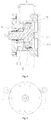
Fig. 3 is a schematic cross-sectional view of the diffuser shown inFig. 1 ; -
Fig. 4 is a schematic cross-sectional view of a pressure drive mechanism in the diffuser shown inFig. 1 ; and -
Fig. 5 is a schematic diagram of the structure of a pressure drive mechanism in the diffuser shown inFig. 1 . - In order to facilitate the understanding of the present disclosure, the present disclosure will be described more comprehensively below with reference to relevant drawings. Preferred embodiments of the present disclosure are shown in the drawings. However, the present disclosure can be implemented in many different forms and is not limited to the embodiments described herein. On the contrary, these embodiments are provided to understand the content of the present disclosure more thoroughly and comprehensively.
- It should be noted that when an element is referred to as being "fixed to" another element, it may be directly on the other element or there may be an intermediate element. When an element is considered to be "connected" with another element, it may be directly connected to the other element or there may be an intermediate element.
- Unless otherwise defined, all technical and scientific terms used herein have the same meanings which are generally understood by those skilled in the technical field of the present disclosure. The terms used in the description of the present disclosure herein are merely intended to describe specific embodiments rather than to limit the present disclosure. The term "and/or" used herein includes any and all combinations of one or more related listed items.
- As shown in
Figs. 1-3 , in some embodiments of the present disclosure, adiffuser 100 is provided. Thediffuser 100 is arranged at an outlet of animpeller 210 in a centrifugal compressor and is configured to increase the airflow pressure. In addition, a width of a pressure diffusion flow channel 20 in thediffuser 100 is adjustable, thus a cooling capacity of the centrifugal compressor during running is adjusted. In this way, so that the centrifugal compressor can provide a proper cooling capacity under both a refrigerating condition and a heating condition. - The
diffuser 100 includes apressure drive mechanism 10, afirst diffuser part 32, a second diffuser part 34 and amovable diffuser part 50; thefirst diffuser part 32 and the second diffuser part 34 are oppositely spaced in an axial direction of the centrifugal compressor; a pressure diffusion flow channel 20 communicating with the outlet of theimpeller 210 is formed between thefirst diffuser part 32 and the second diffuser part 34; and a gas flow flowing out of theimpeller 210 is pressurized in the pressure diffusion flow channel 20. themovable diffuser part 50 is connected with thepressure drive mechanism 10 and is movably arranged on one of thefirst diffuser part 32 and the second diffuser part 34 and can get close to or leave away from the other one of thefirst diffuser part 32 and the second diffuser part 34 under the action of a pressure medium in thepressure drive mechanism 10 so as to adjust an width of the pressure diffusion flow channel 20. In this way, a proper cooling capacity can be provided under both a refrigerating condition and a heating condition to prevent adverse phenomena such as gas flow stall and surging. - In addition, the
pressure drive mechanism 10 applies a thrust to themovable diffuser part 50 through a pressure medium. A pressure of a fluid is determined according to a cooling capacity of a compressor. The pressure medium can generate a positive pressure to themovable diffuser part 50, and the positive pressure is perpendicular to the surface of themovable diffuser part 50. The annularmovable diffuser part 50 can be pushed to move in the axial direction. Themovable diffuser part 50 can be prevented from being inclined and chucked due to a thrust inclined relative to an axis. The reliability and stability of movement of themovable diffuser part 50 are improved. Also, when an annularmovable diffuser part 50 is driven by a plurality ofpressure drive mechanisms 10 spaced in a circumferential direction, the plurality ofpressure drive mechanisms 10 can be connected mutually, pressure mediums in the plurality ofpressure drive mechanisms 10 communicate with each other, and the flowing pressure mediums drive the plurality ofpressure drive mechanisms 10 to move synchronously. Thus, themovable diffuser part 50 is synchronously driven at a plurality of points to move in only the axial direction and remains the same position in other directions, so that themovable diffuser part 50 smoothly moves. Therefore, the reliability of movement of themovable diffuser part 50 is further guaranteed, and thus the reliability of running of the centrifugal compressor is guaranteed. - In addition, compared with a way of adopting a plurality of cam guide rod mechanisms, the way of adopting a
pressure drive mechanism 10 to drive themovable diffuser part 50 can simplify a drive structure, the structure is compact, and space usage is reduced. - Specifically, the
movable diffuser part 50 is arranged on thefirst diffuser part 32, and is movably arranged in a direction close to and away from the second diffuser part 34 under the driving of thepressure drive mechanism 10 so as to adjust a width of the pressure diffusion flow channel 20. - As shown in
Fig. 4 , thepressure drive mechanism 10 includes acylinder 12 and apiston 14, wherein thecylinder 12 is provided with anaccommodating cavity 11; one end of thepiston 14 is slidably arranged in theaccommodating cavity 11; the other end of thepiston 14 extends out of thecylinder 12 and is connected with themovable diffuser part 50; and thepiston 14 is driven to slide by changing the volume of a pressure medium in theaccommodating cavity 11, and in this way themovable diffuser part 50 is driven to move. In other words, thepiston 14 in theaccommodating cavity 11 is driven to move by inflowing and outflowing of a pressure medium in theaccommodating cavity 11. Thus, thepiston 14 drives themovable diffuser part 50 to move and is applied with a pressure perpendicular to the surface of thepiston 14, so that thepiston 14 can slide smoothly, and the accuracy and reliability of running of thepiston 14 and themovable diffuser part 50 are guaranteed. - The
pressure drive mechanism 10 further includes anelastic member 16; thepiston 14 divides theaccommodating cavity 11 into afirst cavity 112 and asecond cavity 114; thefirst cavity 112 allows a pressure medium to flow in or out; theelastic member 16 is accommodated in thesecond cavity 114; and theelastic member 16 abuts between thepiston 14 and the inner wall of thesecond cavity 114 along the moving direction of thepiston 14. When a pressure medium flows into thefirst cavity 112, the volume of thefirst cavity 112 is increased under the action of the pressure medium; meanwhile, thepiston 14 moves to one side of thesecond cavity 114; the volume of thesecond cavity 14 is compressed; and simultaneously, theelastic member 16, located in a moving route of thepiston 14, in thesecond cavity 114 is compressed as well. When the pressure medium in thefirst cavity 112 flows out, an extrusion force applied to the compressedelastic member 16 is lowered, theelastic member 16 is restored, thepiston 14 is driven to move to one side of thefirst cavity 112, and meanwhile the volume of thefirst cavity 112 is lowered. In this way, by filling thefirst cavity 112 with a pressure medium, thepiston 14 can be controlled to move toward thesecond cavity 114 to drive themovable diffuser part 50 to move close to the second diffuser part 34; and by discharging the pressure medium from thecavity 112, thepiston 14 can be controlled to move toward thefirst cavity 112 to drive themovable diffuser part 50 to move away from the second diffuser part 34, thereby changing the width of the pressure diffusion flow channel 20. - Specifically, the
piston 14 includes aplug body 141 and arod body 143; theplug body 141 can be slidably arranged in theaccommodating cavity 11; therod body 143 is connected to one side of theplug body 141, extends out of thecylinder 12 via thesecond cavity 14 and is connected with themovable diffuser part 50, so that themovable diffuser part 50 is driven to move by therod body 143; in addition, therod body 143 is externally sleeved with theelastic member 16; the two ends of theelastic member 16 respectively abut against theplug body 141 and the inner wall of thesecond cavity 114; and meanwhile theelastic member 16 is installed by virtue of therod body 143. Specifically, the end face, facing toward thesecond cavity 114, of theplug body 141 is provided with an annular groove; the two ends of theelastic member 16 respectively abut against the bottom surface of the annular groove and the inner wall, away from theplug body 141, of thesecond cavity 114 in the axial direction. - Optionally, a sealing part may be arranged between the
plug body 141 and the inner wall of theaccommodating cavity 11; the sealing part is configured to seal theplug body 141 to prevent a pressure medium in thefirst cavity 112 and on one side of theplug body 141 from flowing into thesecond cavity 114 and being mixed with a refrigerant after entering the pressure diffusion flow channel 20, and thus influences on normal work of the refrigerant are avoided. - As shown in
Fig. 5 , thepressure drive mechanism 10 further includes an inlet electromagnetic valve 17 and an outletelectromagnetic valve 18; thefirst cavity 112 is provided with a medium inlet and a medium outlet; the inlet electromagnetic valve 17 is arranged at the medium inlet and configured to control the connection or disconnection of inflowing pressure medium; and the outletelectromagnetic valve 18 is arranged at the medium outlet and configured to control the connection or disconnection of outflowing pressure medium. In a process of adjusting the pressure medium, the pressure medium is flexibly controlled to flow in or flow out by powering on or powering off the inlet electromagnetic valve 17 and the outletelectromagnetic valve 18. - As shown in
Fig. 1 andFig. 2 , further, themovable diffuser part 50 is annular; there are a plurality ofpressure drive mechanisms 10; the plurality ofpressure drive mechanisms 10 are spaced in a circumferential direction of themovable diffuser part 50 and are all connected with themovable diffuser part 50; moreover, thepressure drive mechanisms 10 are connected in series or in parallel through connecting pipes so as to synchronously drive themovable diffuser part 50 to move from a plurality of points; and thus a stable and reliable driving process is achieved. - As shown in
Fig. 3 , specifically, the surface, facing toward the second diffuser part 34, of thefirst diffuser part 32 is provided with agroove 33; thegroove 33 communicates with the pressure diffusion flow channel 20; themovable diffuser part 50 is movably arranged in thegroove 33 and is accommodated in thegroove 33. Optionally, thegroove 33 is configured in a ring shape and is matched with themovable diffuser part 50 in shape. - Further, the
movable diffuser part 50 includes a firstinclined surface 52 facing toward the second diffuser part 34, and the firstinclined surface 52 is inclined to get close to the second diffuser part 34 along the flowing direction of a gas flow in the pressure diffusion flow channel 20, thereby forming a flow channel with a gradually-minimized section in the flowing direction of the gas flow, gathering a gas which is discharged from theimpeller 210 and realizing pressure diffusion of the gas. - More further, the surface, facing toward the second diffuser part 34, of the
first diffuser part 32 includes a secondinclined surface 31; and the secondinclined surface 31 is inclined to get close to the second diffuser part 34 along the flowing direction of a gas flow in the pressure diffusion flow channel 20, thereby further forming a flow channel with a gradually-reduced section in the flowing direction of the gas flow and further increasing the pressure of the gas. - Optionally, after the
movable diffuser part 50 is moved into thegroove 33, for example, when themovable diffuser part 50 moves to an extreme position close to the bottom surface of thegroove 33, the firstinclined surface 52 is flush with the secondinclined surface 31 based on a maximum cooling capacity of the compressor; and the firstinclined surface 52 and the secondinclined surface 31 obliquely extend in the same direction, so that the firstinclined surface 52 and the secondinclined surface 31 are smoothly butted in a transition manner to realize smooth pressure diffusion. - In order to prevent the
movable diffuser part 50 from generating friction and collision with the second diffuser part 34 in an adjustment process, as shown inFig. 3 , a gap is formed between themovable diffuser part 50 and the bottom surface of thegroove 33 when themovable diffuser part 50 moves to an extreme position close to the bottom surface of thegroove 33. As shown inFig. 4 , in order to maintain the gap, the end face, away from the second diffuser part 34, of thecylinder 12 is provided with acover 35; thecover 35 is configured to seal thefirst cavity 112; the end face, facing toward thecover 35, of thepiston 14 is provided with afirst lug boss 144; the end face, facing toward thepiston 14, of thecover 35 is provided with asecond lug boss 351; and themovable diffuser part 50 moves to an extreme position close to the bottom surface of thegroove 33 when thepiston 14 moves toward thecover 35 until thefirst lug boss 144 abuts against thesecond lug boss 351. - In some embodiments of the present disclosure, a centrifugal compressor is further provided and includes the
diffuser 100 of the above embodiments. Themovable diffuser part 50 is arranged at the outlet of theimpeller 210 of the centrifugal compressor, and a width of the pressure diffusion flow channel 20 is adjusted according to working conditions. In this way, the centrifugal compressor runs reliably under different working conditions. Particularly, when the cooling capacities under different working conditions have a great difference, the centrifugal compressor can be adjusted to run close to an optimal design point under each working condition, thereby guaranteeing the running efficiency, widening the range of small-load running of the centrifugal compressor and reducing phenomena such as stall and surging. - Specifically, a plurality of
pressure drive mechanisms 10 are spaced in a circumferential direction of the annularmovable diffuser part 50; subsequently a pressure medium in eachpressure drive mechanism 10 is controlled to flow in and flow out via the inlet electromagnetic valve 17 and the outletelectromagnetic valve 18; and thus themovable diffuser part 50 is controlled to move. - When the centrifugal compressor runs under a first load condition which is a heavy-load condition, the inlet electromagnetic valve 17 is closed, the outlet
electromagnetic valve 18 is opened, a pressure in thefirst cavity 112 is decreased, and thepiston 14 is kept at the rightmost end under the action of theelastic member 16. In this way, themovable diffuser part 50 connected with thepiston 14 moves to the rightmost side of thegroove 33. At the moment, the pressure diffusion flow channel 20 at the outlet of theimpeller 210 is widest, and theimpeller 210 can exert the highest power. - When the centrifugal compressor runs under a second load condition which is a small-load condition, a second load is smaller than a first load; if the pressure diffusion flow channel 20 is still widest, a refrigerant at the outlet of the
impeller 210 may have phenomena such as stall and surging, and accordingly the centrifugal compressor stops running. Therefore, at the moment, the outletelectromagnetic valve 18 should be closed and the inlet electromagnetic valve 17 should be opened to allow a pressure medium to enter thefirst cavity 112. In this way, a pressure in thefirst cavity 112 is increased, thus theelastic member 16 is compressed to move thepiston 14 leftwards to drive themovable diffuser part 50 to move leftwards; the pressure diffusion flow channel 20 at the outlet of theimpeller 210 is narrowed, and the flowing speed of a refrigerant at the outlet of theimpeller 210 is increased, thereby effectively preventing surging, greatly lowering a minimum load of the centrifugal compressor and widening the running range. - All technical features of the above-mentioned embodiments can be combined randomly; in order to make the description concise, not all possible combinations of the various technical features in the above-mentioned embodiments are described, however, as long as there is no contradiction between the combinations of these technical features, all should be considered as the scope of this specification.
- The above embodiments merely show some implementations of the present disclosure, are described specifically in detail, but cannot be understood as a limitation to the scope of a patent for an disclosure. It should be noted that some transformations and improvements can be made by those of ordinary skill in the art without departing the concept of the present disclosure, and all these transformations and improvements are included in the protection scope of the present disclosure. Therefore, the protection scope of the patent of the present disclosure is subject to the described claims.
Claims (13)
- A diffuser (100), comprising:a pressure drive mechanism (10);a first diffuser part (32) and a second diffuser part (34) spaced oppositely, wherein a pressure diffusion flow channel (20) for pressure diffusion of a gas is formed between the first diffuser part (32) and the second diffuser part (34), anda movable diffuser part (50), connected with the pressure drive mechanism (10) and movably arranged on one of the first diffuser part (32) and the second diffuser part (34); wherein the movable diffuser part (50) is configured to get close to or leave away from the other one of the first diffuser part (32) and the second diffuser part (34) under the action of a pressure medium in the pressure drive mechanism (10), so as to adjust a width of the pressure diffusion flow channel (20).
- The diffuser (100) according to claim 1, further comprising connecting pipes, wherein the movable diffuser part (50) is annular; there are a plurality of pressure drive mechanisms (10); the pressure drive mechanisms (10) are spaced in a circumferential direction of the movable diffuser part (50) and are connected with the movable diffuser part (50); and the pressure drive mechanisms (10) are connected in series or in parallel through the connecting pipes.
- The diffuser (100) according to claim 1, wherein the surface, facing toward the second diffuser part (34), of the first diffuser part (32) is provided with a groove (33); the groove (33) communicates with the pressure diffusion flow channel (20); and the movable diffuser part (50) is movably arranged in the groove (33).
- The diffuser (100) according to claim 3, wherein the movable diffuser part (50) comprises a first inclined surface (52) facing toward the second diffuser part (34), and the first inclined surface (52) is inclined to get close to the second diffuser part (34) along the flowing direction of a gas flow in the pressure diffusion flow channel (20).
- The diffuser (100) according to claim 4, wherein the surface, facing toward the second diffuser part (34), of the first diffuser part (32) comprises a second inclined surface (31) second diffuser part, and the second inclined surface (31) is inclined to get close to the second diffuser part (34) along the flowing direction of a gas flow in the pressure diffusion flow channel (20).
- The diffuser (100) according to claim 5, wherein the first inclined surface (52) and the second inclined surface (31) extend obliquely in the same direction; and the movable diffuser part (50) is configured to make the first inclined surface (52) be flush with the second inclined surface (31) after moving to an extreme position close to the bottom surface of the groove (33).
- The diffuser (100) according to any one of claims 1 to 6, wherein the pressure drive mechanism (10) comprises a cylinder (12) and a piston (14), wherein the cylinder (12) has an accommodating cavity (11); one end of the piston (14) is slidably arranged in the accommodating cavity (11); the other end of the piston (14) extends out of the cylinder (12) and is connected with the movable diffuser part (50); and the piston (14) is configured to be driven to slide by changing the volume of a pressure medium in the accommodating cavity (11).
- The diffuser (100) according to claim 7, wherein the pressure drive mechanism (10) comprises an elastic member (16); the piston (14) divides the accommodating cavity (11) into a first cavity (112) and a second cavity (114); the first cavity (112) is configured to allow the pressure medium to flow in or out; the elastic member (16) is accommodated in the second cavity (114); and the elastic member (16) abuts between the piston (14) and the inner wall of the second cavity (114) along the moving direction of the piston (14).
- The diffuser (100) according to claim 8, wherein the piston (14) comprises a plug body (141) and a rod body (143); the plug body (141) is slidably arranged in the accommodating cavity (11) along an axial direction; the rod body (143) is connected to an axial side of the piston body (141) and extends out of the cylinder (12) via the second cavity (114) and is connected with the movable diffuser part (50); the elastic member (16) sleeves the outside of the rod body (143); and the two ends of the elastic member (16) respectively abut against the plug body (141) and the inner wall of the second cavity (114).
- The diffuser (100) according to claim 8, wherein the pressure drive mechanism (10) comprises an inlet electromagnetic valve (17) and an outlet electromagnetic valve (18); the first cavity (112) is provided with a medium inlet and a medium outlet; the inlet electromagnetic valve (17) is arranged at the medium inlet so as to control the connection or disconnection of inflowing pressure medium; and the outlet electromagnetic valve (18) is arranged at the medium outlet and configured to control the connection or disconnection of outflowing pressure medium.
- The diffuser (100) according to any one of claims 1 to 6, wherein the surface, facing toward the second diffuser part (34), of the first diffuser part (32) is provided with a groove (33); the groove (33) communicates with the pressure diffusion flow channel (20); the movable diffuser part (50) is movably arranged in the groove (33); and
the movable diffuser part (50) is configured to form a preset gap with the bottom surface of the groove (33) after moving to an extreme position close to the bottom surface of the groove (33). - The diffuser (100) according to claim 11, wherein the pressure drive mechanism (10) comprises a cylinder (12), a piston (14) and a cover (35), wherein the cylinder (12) is provided with an accommodating cavity (11); one end of the piston (14) is slidably arranged in the accommodating cavity (11); the other end of the piston (14) extends out of the cylinder (12) and is connected with the movable diffuser part (50); the cover (35) seals the accommodating cavity (11); and
the end, facing toward the cover (35), of the piston (14) is provided with a first lug boss (144); the end face, facing toward the piston (14), of the cover (35) is provided with a second lug boss (351); and the movable diffuser part (50) is configured to form the preset gap between the movable diffuser part (50) and the bottom surface of the groove (33) after moving until the first lug boss (144) abuts against the second lug boss (351). - A centrifugal compressor, comprising:an impeller (210); andthe diffuser (100) according to any one of claims 1-12;wherein the pressure diffusion flow channel (20) communicates with an outlet of the impeller (210).
Applications Claiming Priority (2)
| Application Number | Priority Date | Filing Date | Title |
|---|---|---|---|
| CN201811542396.7A CN109356886A (en) | 2018-12-17 | 2018-12-17 | Centrifugal compressor and diffuser device |
| PCT/CN2019/112761 WO2020125193A1 (en) | 2018-12-17 | 2019-10-23 | Centrifugal compressor and diffuser device |
Publications (3)
| Publication Number | Publication Date |
|---|---|
| EP3851682A1 true EP3851682A1 (en) | 2021-07-21 |
| EP3851682A4 EP3851682A4 (en) | 2022-01-26 |
| EP3851682B1 EP3851682B1 (en) | 2025-12-17 |
Family
ID=65329009
Family Applications (1)
| Application Number | Title | Priority Date | Filing Date |
|---|---|---|---|
| EP19900666.9A Active EP3851682B1 (en) | 2018-12-17 | 2019-10-23 | Centrifugal compressor and diffuser device |
Country Status (6)
| Country | Link |
|---|---|
| US (1) | US11578733B2 (en) |
| EP (1) | EP3851682B1 (en) |
| CN (1) | CN109356886A (en) |
| MY (1) | MY207167A (en) |
| PH (1) | PH12021550923A1 (en) |
| WO (1) | WO2020125193A1 (en) |
Families Citing this family (7)
| Publication number | Priority date | Publication date | Assignee | Title |
|---|---|---|---|---|
| CN109356886A (en) * | 2018-12-17 | 2019-02-19 | 珠海格力电器股份有限公司 | Centrifugal compressor and diffuser device |
| US11885352B1 (en) | 2022-09-12 | 2024-01-30 | Hamilton Sundstrand Corporation | Variable channel diffuser with moving floor |
| US11773870B1 (en) | 2022-09-12 | 2023-10-03 | Hamilton Sundstrand Corporation | Variable channel diffuser |
| US11873839B1 (en) | 2022-09-12 | 2024-01-16 | Hamilton Sundstrand Corporation | Variable vaneless diffuser with moving floor |
| US12135039B2 (en) | 2022-09-12 | 2024-11-05 | Hamilton Sundstrand Corporation | Variable pipe diffuser |
| CN117167330A (en) * | 2023-08-11 | 2023-12-05 | 珠海格力电器股份有限公司 | Centrifugal compressor and control method thereof |
| CN117627960A (en) * | 2023-12-25 | 2024-03-01 | 珠海格力电器股份有限公司 | Diffusers and compressors |
Family Cites Families (35)
| Publication number | Priority date | Publication date | Assignee | Title |
|---|---|---|---|---|
| DE234751C (en) * | 1911-05-19 | |||
| US3251539A (en) * | 1963-05-15 | 1966-05-17 | Westinghouse Electric Corp | Centrifugal gas compressors |
| NL126489C (en) | 1964-05-11 | |||
| US3426964A (en) | 1966-10-11 | 1969-02-11 | Dresser Ind | Compressor apparatus |
| US3478955A (en) * | 1968-03-11 | 1969-11-18 | Dresser Ind | Variable area diffuser for compressor |
| US4219305A (en) * | 1978-12-26 | 1980-08-26 | Carrier Corporation | Diffuser control |
| US4257733A (en) * | 1978-12-26 | 1981-03-24 | Carrier Corporation | Diffuser control |
| EP0034915A1 (en) * | 1980-02-22 | 1981-09-02 | Holset Engineering Company Limited | Radially inward flow turbine |
| US4416583A (en) * | 1980-04-04 | 1983-11-22 | Carrier Corporation | Centrifugal vapor compressor |
| US4378194A (en) * | 1980-10-02 | 1983-03-29 | Carrier Corporation | Centrifugal compressor |
| US4460310A (en) * | 1982-06-28 | 1984-07-17 | Carrier Corporation | Diffuser throttle ring control |
| US4579509A (en) * | 1983-09-22 | 1986-04-01 | Dresser Industries, Inc. | Diffuser construction for a centrifugal compressor |
| US4643639A (en) * | 1984-12-24 | 1987-02-17 | Sundstrand Corporation | Adjustable centrifugal pump |
| US4844690A (en) * | 1985-01-24 | 1989-07-04 | Carrier Corporation | Diffuser vane seal for a centrifugal compressor |
| US4611969A (en) * | 1985-08-19 | 1986-09-16 | Carrier Corporation | Calibrating apparatus and method for a movable diffuser wall in a centrifugal compressor |
| JPH0663897U (en) * | 1993-02-17 | 1994-09-09 | 石川島播磨重工業株式会社 | Centrifugal compressor with vaneless diffuser |
| JPH09100799A (en) * | 1995-10-06 | 1997-04-15 | Ishikawajima Harima Heavy Ind Co Ltd | Centrifugal compressor |
| US6139262A (en) * | 1998-05-08 | 2000-10-31 | York International Corporation | Variable geometry diffuser |
| ITTO20010505A1 (en) * | 2001-05-25 | 2002-11-25 | Iveco Motorenforschung Ag | VARIABLE GEOMETRY TURBINE. |
| US6872050B2 (en) * | 2002-12-06 | 2005-03-29 | York International Corporation | Variable geometry diffuser mechanism |
| US7905102B2 (en) * | 2003-10-10 | 2011-03-15 | Johnson Controls Technology Company | Control system |
| DE60324340D1 (en) * | 2003-11-12 | 2008-12-04 | Honeywell Int Inc | COMPRESSOR WITH ADJUSTABLE DIFFUSER WALL AND METHOD THEREFOR |
| DE102006009354A1 (en) * | 2006-03-01 | 2007-09-06 | Bayerische Motoren Werke Ag | Centrifuge compressor, for a turbocharger, has a hollow elastic body to give a wide adjustment of the flow cross section surface of the diffuser |
| JP5029024B2 (en) * | 2007-01-18 | 2012-09-19 | 株式会社Ihi | Centrifugal compressor |
| CN101195141A (en) * | 2007-12-30 | 2008-06-11 | 重庆长安汽车股份有限公司 | Post rod hydraulic pressure balancing device of exterior cladding element draw forming die of vehicle |
| JP5056447B2 (en) * | 2008-02-06 | 2012-10-24 | 株式会社Ihi | Turbo compressor and refrigerator |
| CN102597532B (en) * | 2009-11-17 | 2014-09-17 | 丰田自动车株式会社 | Centrifugal compressor and turbo supercharger |
| JP5348316B2 (en) * | 2010-04-13 | 2013-11-20 | トヨタ自動車株式会社 | Centrifugal compressor |
| CN103261703B (en) * | 2010-12-10 | 2015-04-29 | 丰田自动车株式会社 | Centrifugal compressor |
| JP6256142B2 (en) * | 2014-03-26 | 2018-01-10 | 株式会社豊田自動織機 | Centrifugal compressor |
| CN107975498B (en) * | 2016-10-24 | 2021-08-31 | 开利公司 | Diffuser for centrifugal compressor and centrifugal compressor with diffuser |
| CN107642506A (en) * | 2017-10-24 | 2018-01-30 | 珠海格力电器股份有限公司 | Regulator structure and centrifugal compressor with same |
| CN107654419A (en) * | 2017-10-30 | 2018-02-02 | 珠海格力电器股份有限公司 | Adjustable diffuser and centrifugal compressor |
| CN109356886A (en) * | 2018-12-17 | 2019-02-19 | 珠海格力电器股份有限公司 | Centrifugal compressor and diffuser device |
| CN209294139U (en) * | 2018-12-17 | 2019-08-23 | 珠海格力电器股份有限公司 | Centrifugal compressor and diffuser device |
-
2018
- 2018-12-17 CN CN201811542396.7A patent/CN109356886A/en active Pending
-
2019
- 2019-10-23 WO PCT/CN2019/112761 patent/WO2020125193A1/en not_active Ceased
- 2019-10-23 PH PH1/2021/550923A patent/PH12021550923A1/en unknown
- 2019-10-23 EP EP19900666.9A patent/EP3851682B1/en active Active
- 2019-10-23 MY MYPI2021002151A patent/MY207167A/en unknown
- 2019-10-23 US US17/287,885 patent/US11578733B2/en active Active
Also Published As
| Publication number | Publication date |
|---|---|
| US11578733B2 (en) | 2023-02-14 |
| PH12021550923A1 (en) | 2022-05-02 |
| US20210348622A1 (en) | 2021-11-11 |
| EP3851682B1 (en) | 2025-12-17 |
| MY207167A (en) | 2025-02-04 |
| EP3851682A4 (en) | 2022-01-26 |
| WO2020125193A1 (en) | 2020-06-25 |
| CN109356886A (en) | 2019-02-19 |
Similar Documents
| Publication | Publication Date | Title |
|---|---|---|
| US11578733B2 (en) | Centrifugal compressor and diffuser | |
| US10927972B2 (en) | Flow rate control valve | |
| US10767787B2 (en) | Electrically-driven flow rate control valve | |
| US7540729B2 (en) | Vane cell pump | |
| KR101789899B1 (en) | Vane pump with multiple control chambers | |
| EP2924299B1 (en) | Centrifugal compressor | |
| JP6574311B2 (en) | Automotive coolant pump | |
| JPS61171900A (en) | Variable width diffuser assembly of centrifugal machine | |
| KR20230022986A (en) | sliding parts | |
| US20130251571A1 (en) | Vane Pump | |
| CN105745452B (en) | unloading mechanism | |
| US10267310B2 (en) | Variable pressure pump with hydraulic passage | |
| EP3798446B1 (en) | Pump body assembly and compressor having same | |
| CN116241457A (en) | High pressure variable vane pump with vane pins | |
| US7946833B2 (en) | Variable displacement vane pump | |
| JP2010106746A (en) | Centrifugal compressor | |
| CN107110157B (en) | Helical-lobe compressor | |
| CN101044322B (en) | Pumps with optional outlet pressure | |
| US20060207247A1 (en) | Actuator | |
| TW201942481A (en) | Air cylinder | |
| CN209294139U (en) | Centrifugal compressor and diffuser device | |
| KR20220100707A (en) | sliding parts | |
| JP2017020562A (en) | Relief valve | |
| US20130089456A1 (en) | Cartridge Style Binary Vane Pump | |
| JP2014092087A (en) | Screw compressor |
Legal Events
| Date | Code | Title | Description |
|---|---|---|---|
| STAA | Information on the status of an ep patent application or granted ep patent |
Free format text: STATUS: THE INTERNATIONAL PUBLICATION HAS BEEN MADE |
|
| PUAI | Public reference made under article 153(3) epc to a published international application that has entered the european phase |
Free format text: ORIGINAL CODE: 0009012 |
|
| STAA | Information on the status of an ep patent application or granted ep patent |
Free format text: STATUS: REQUEST FOR EXAMINATION WAS MADE |
|
| 17P | Request for examination filed |
Effective date: 20210413 |
|
| AK | Designated contracting states |
Kind code of ref document: A1 Designated state(s): AL AT BE BG CH CY CZ DE DK EE ES FI FR GB GR HR HU IE IS IT LI LT LU LV MC MK MT NL NO PL PT RO RS SE SI SK SM TR |
|
| A4 | Supplementary search report drawn up and despatched |
Effective date: 20220104 |
|
| RIC1 | Information provided on ipc code assigned before grant |
Ipc: F04D 29/46 20060101AFI20211221BHEP |
|
| DAV | Request for validation of the european patent (deleted) | ||
| DAX | Request for extension of the european patent (deleted) | ||
| P01 | Opt-out of the competence of the unified patent court (upc) registered |
Effective date: 20230530 |
|
| STAA | Information on the status of an ep patent application or granted ep patent |
Free format text: STATUS: EXAMINATION IS IN PROGRESS |
|
| 17Q | First examination report despatched |
Effective date: 20230720 |
|
| GRAP | Despatch of communication of intention to grant a patent |
Free format text: ORIGINAL CODE: EPIDOSNIGR1 |
|
| STAA | Information on the status of an ep patent application or granted ep patent |
Free format text: STATUS: GRANT OF PATENT IS INTENDED |
|
| INTG | Intention to grant announced |
Effective date: 20251006 |
|
| GRAS | Grant fee paid |
Free format text: ORIGINAL CODE: EPIDOSNIGR3 |
|
| GRAA | (expected) grant |
Free format text: ORIGINAL CODE: 0009210 |
|
| STAA | Information on the status of an ep patent application or granted ep patent |
Free format text: STATUS: THE PATENT HAS BEEN GRANTED |
|
| AK | Designated contracting states |
Kind code of ref document: B1 Designated state(s): AL AT BE BG CH CY CZ DE DK EE ES FI FR GB GR HR HU IE IS IT LI LT LU LV MC MK MT NL NO PL PT RO RS SE SI SK SM TR |
|
| REG | Reference to a national code |
Ref country code: CH Ref legal event code: F10 Free format text: ST27 STATUS EVENT CODE: U-0-0-F10-F00 (AS PROVIDED BY THE NATIONAL OFFICE) Effective date: 20251217 Ref country code: GB Ref legal event code: FG4D |
|
| REG | Reference to a national code |
Ref country code: DE Ref legal event code: R096 Ref document number: 602019079419 Country of ref document: DE |
|
| REG | Reference to a national code |
Ref country code: LT Ref legal event code: MG9D |
|
| PG25 | Lapsed in a contracting state [announced via postgrant information from national office to epo] |
Ref country code: NO Free format text: LAPSE BECAUSE OF FAILURE TO SUBMIT A TRANSLATION OF THE DESCRIPTION OR TO PAY THE FEE WITHIN THE PRESCRIBED TIME-LIMIT Effective date: 20260317 |
|
| PG25 | Lapsed in a contracting state [announced via postgrant information from national office to epo] |
Ref country code: HR Free format text: LAPSE BECAUSE OF FAILURE TO SUBMIT A TRANSLATION OF THE DESCRIPTION OR TO PAY THE FEE WITHIN THE PRESCRIBED TIME-LIMIT Effective date: 20251217 Ref country code: FI Free format text: LAPSE BECAUSE OF FAILURE TO SUBMIT A TRANSLATION OF THE DESCRIPTION OR TO PAY THE FEE WITHIN THE PRESCRIBED TIME-LIMIT Effective date: 20251217 |
|
| PG25 | Lapsed in a contracting state [announced via postgrant information from national office to epo] |
Ref country code: RS Free format text: LAPSE BECAUSE OF FAILURE TO SUBMIT A TRANSLATION OF THE DESCRIPTION OR TO PAY THE FEE WITHIN THE PRESCRIBED TIME-LIMIT Effective date: 20260317 |
|
| REG | Reference to a national code |
Ref country code: NL Ref legal event code: MP Effective date: 20251217 |
|
| PG25 | Lapsed in a contracting state [announced via postgrant information from national office to epo] |
Ref country code: LV Free format text: LAPSE BECAUSE OF FAILURE TO SUBMIT A TRANSLATION OF THE DESCRIPTION OR TO PAY THE FEE WITHIN THE PRESCRIBED TIME-LIMIT Effective date: 20251217 |
|
| PG25 | Lapsed in a contracting state [announced via postgrant information from national office to epo] |
Ref country code: BG Free format text: LAPSE BECAUSE OF FAILURE TO SUBMIT A TRANSLATION OF THE DESCRIPTION OR TO PAY THE FEE WITHIN THE PRESCRIBED TIME-LIMIT Effective date: 20251217 |
|
| REG | Reference to a national code |
Ref country code: AT Ref legal event code: MK05 Ref document number: 1868704 Country of ref document: AT Kind code of ref document: T Effective date: 20251217 |
|
| PG25 | Lapsed in a contracting state [announced via postgrant information from national office to epo] |
Ref country code: NL Free format text: LAPSE BECAUSE OF FAILURE TO SUBMIT A TRANSLATION OF THE DESCRIPTION OR TO PAY THE FEE WITHIN THE PRESCRIBED TIME-LIMIT Effective date: 20251217 |
|
| PG25 | Lapsed in a contracting state [announced via postgrant information from national office to epo] |
Ref country code: LT Free format text: LAPSE BECAUSE OF FAILURE TO SUBMIT A TRANSLATION OF THE DESCRIPTION OR TO PAY THE FEE WITHIN THE PRESCRIBED TIME-LIMIT Effective date: 20251217 |
|
| PG25 | Lapsed in a contracting state [announced via postgrant information from national office to epo] |
Ref country code: SM Free format text: LAPSE BECAUSE OF FAILURE TO SUBMIT A TRANSLATION OF THE DESCRIPTION OR TO PAY THE FEE WITHIN THE PRESCRIBED TIME-LIMIT Effective date: 20251217 |
|
| PG25 | Lapsed in a contracting state [announced via postgrant information from national office to epo] |
Ref country code: ES Free format text: LAPSE BECAUSE OF FAILURE TO SUBMIT A TRANSLATION OF THE DESCRIPTION OR TO PAY THE FEE WITHIN THE PRESCRIBED TIME-LIMIT Effective date: 20251217 |
|
| PG25 | Lapsed in a contracting state [announced via postgrant information from national office to epo] |
Ref country code: PL Free format text: LAPSE BECAUSE OF FAILURE TO SUBMIT A TRANSLATION OF THE DESCRIPTION OR TO PAY THE FEE WITHIN THE PRESCRIBED TIME-LIMIT Effective date: 20251217 |
|
| PG25 | Lapsed in a contracting state [announced via postgrant information from national office to epo] |
Ref country code: IT Free format text: LAPSE BECAUSE OF FAILURE TO SUBMIT A TRANSLATION OF THE DESCRIPTION OR TO PAY THE FEE WITHIN THE PRESCRIBED TIME-LIMIT Effective date: 20251217 |
|
| PG25 | Lapsed in a contracting state [announced via postgrant information from national office to epo] |
Ref country code: AT Free format text: LAPSE BECAUSE OF FAILURE TO SUBMIT A TRANSLATION OF THE DESCRIPTION OR TO PAY THE FEE WITHIN THE PRESCRIBED TIME-LIMIT Effective date: 20251217 |
|
| PG25 | Lapsed in a contracting state [announced via postgrant information from national office to epo] |
Ref country code: EE Free format text: LAPSE BECAUSE OF FAILURE TO SUBMIT A TRANSLATION OF THE DESCRIPTION OR TO PAY THE FEE WITHIN THE PRESCRIBED TIME-LIMIT Effective date: 20251217 |
|
| PG25 | Lapsed in a contracting state [announced via postgrant information from national office to epo] |
Ref country code: PT Free format text: LAPSE BECAUSE OF FAILURE TO SUBMIT A TRANSLATION OF THE DESCRIPTION OR TO PAY THE FEE WITHIN THE PRESCRIBED TIME-LIMIT Effective date: 20260417 Ref country code: IS Free format text: LAPSE BECAUSE OF FAILURE TO SUBMIT A TRANSLATION OF THE DESCRIPTION OR TO PAY THE FEE WITHIN THE PRESCRIBED TIME-LIMIT Effective date: 20260417 |
|
| PG25 | Lapsed in a contracting state [announced via postgrant information from national office to epo] |
Ref country code: CZ Free format text: LAPSE BECAUSE OF FAILURE TO SUBMIT A TRANSLATION OF THE DESCRIPTION OR TO PAY THE FEE WITHIN THE PRESCRIBED TIME-LIMIT Effective date: 20251217 |
|
| PG25 | Lapsed in a contracting state [announced via postgrant information from national office to epo] |
Ref country code: SK Free format text: LAPSE BECAUSE OF FAILURE TO SUBMIT A TRANSLATION OF THE DESCRIPTION OR TO PAY THE FEE WITHIN THE PRESCRIBED TIME-LIMIT Effective date: 20251217 |
|
| PG25 | Lapsed in a contracting state [announced via postgrant information from national office to epo] |
Ref country code: SE Free format text: LAPSE BECAUSE OF FAILURE TO SUBMIT A TRANSLATION OF THE DESCRIPTION OR TO PAY THE FEE WITHIN THE PRESCRIBED TIME-LIMIT Effective date: 20251217 |