EP3851382A1 - Halo light assembly - Google Patents
Halo light assembly Download PDFInfo
- Publication number
- EP3851382A1 EP3851382A1 EP21152178.6A EP21152178A EP3851382A1 EP 3851382 A1 EP3851382 A1 EP 3851382A1 EP 21152178 A EP21152178 A EP 21152178A EP 3851382 A1 EP3851382 A1 EP 3851382A1
- Authority
- EP
- European Patent Office
- Prior art keywords
- laminate
- transparency
- layer
- halo
- light source
- Prior art date
- Legal status (The legal status is an assumption and is not a legal conclusion. Google has not performed a legal analysis and makes no representation as to the accuracy of the status listed.)
- Granted
Links
Images



Classifications
-
- B—PERFORMING OPERATIONS; TRANSPORTING
- B64—AIRCRAFT; AVIATION; COSMONAUTICS
- B64D—EQUIPMENT FOR FITTING IN OR TO AIRCRAFT; FLIGHT SUITS; PARACHUTES; ARRANGEMENT OR MOUNTING OF POWER PLANTS OR PROPULSION TRANSMISSIONS IN AIRCRAFT
- B64D47/00—Equipment not otherwise provided for
- B64D47/02—Arrangements or adaptations of signal or lighting devices
- B64D47/04—Arrangements or adaptations of signal or lighting devices the lighting devices being primarily intended to illuminate the way ahead
-
- F—MECHANICAL ENGINEERING; LIGHTING; HEATING; WEAPONS; BLASTING
- F21—LIGHTING
- F21S—NON-PORTABLE LIGHTING DEVICES; SYSTEMS THEREOF; VEHICLE LIGHTING DEVICES SPECIALLY ADAPTED FOR VEHICLE EXTERIORS
- F21S41/00—Illuminating devices specially adapted for vehicle exteriors, e.g. headlamps
- F21S41/10—Illuminating devices specially adapted for vehicle exteriors, e.g. headlamps characterised by the light source
- F21S41/14—Illuminating devices specially adapted for vehicle exteriors, e.g. headlamps characterised by the light source characterised by the type of light source
- F21S41/141—Light emitting diodes [LED]
- F21S41/151—Light emitting diodes [LED] arranged in one or more lines
-
- F—MECHANICAL ENGINEERING; LIGHTING; HEATING; WEAPONS; BLASTING
- F21—LIGHTING
- F21S—NON-PORTABLE LIGHTING DEVICES; SYSTEMS THEREOF; VEHICLE LIGHTING DEVICES SPECIALLY ADAPTED FOR VEHICLE EXTERIORS
- F21S41/00—Illuminating devices specially adapted for vehicle exteriors, e.g. headlamps
- F21S41/10—Illuminating devices specially adapted for vehicle exteriors, e.g. headlamps characterised by the light source
- F21S41/19—Attachment of light sources or lamp holders
-
- B—PERFORMING OPERATIONS; TRANSPORTING
- B64—AIRCRAFT; AVIATION; COSMONAUTICS
- B64D—EQUIPMENT FOR FITTING IN OR TO AIRCRAFT; FLIGHT SUITS; PARACHUTES; ARRANGEMENT OR MOUNTING OF POWER PLANTS OR PROPULSION TRANSMISSIONS IN AIRCRAFT
- B64D2203/00—Aircraft or airfield lights using LEDs
-
- F—MECHANICAL ENGINEERING; LIGHTING; HEATING; WEAPONS; BLASTING
- F21—LIGHTING
- F21W—INDEXING SCHEME ASSOCIATED WITH SUBCLASSES F21K, F21L, F21S and F21V, RELATING TO USES OR APPLICATIONS OF LIGHTING DEVICES OR SYSTEMS
- F21W2107/00—Use or application of lighting devices on or in particular types of vehicles
- F21W2107/30—Use or application of lighting devices on or in particular types of vehicles for aircraft
-
- F—MECHANICAL ENGINEERING; LIGHTING; HEATING; WEAPONS; BLASTING
- F21—LIGHTING
- F21Y—INDEXING SCHEME ASSOCIATED WITH SUBCLASSES F21K, F21L, F21S and F21V, RELATING TO THE FORM OR THE KIND OF THE LIGHT SOURCES OR OF THE COLOUR OF THE LIGHT EMITTED
- F21Y2115/00—Light-generating elements of semiconductor light sources
- F21Y2115/10—Light-emitting diodes [LED]
Definitions
- the present disclosure relates to aircraft lighting systems, and, more specifically, to aircraft light assembly with halo lighting.
- Aircraft often have one or more light assemblies configured to allow a pilot to see a landing area, to allow a pilot to see during taxi, or the like.
- Various manufacturers desire different light assemblies for their aircraft lighting systems for brand recognition, or the like.
- a halo light assembly comprises: a bevel including an aperture defining an inner surface; a laminate transparency coupled to the bevel, the laminate transparency disposed in the aperture, the laminate transparency configured to abut the bevel, the laminate transparency including an internal surface, an external surface, and a diffusion layer, the diffusion layer disposed on the internal surface of the laminate transparency; and a light source coupled to the bevel and disposed adjacent to the laminate transparency, the light source extending around a perimeter of the laminate transparency, the light source oriented inward toward the laminate transparency.
- the light source may comprise a flexible strip and a plurality of lights.
- the plurality of lights may be embedded in the flexible strip.
- the laminate transparency may further comprise a first laminate layer and a second laminate layer, the second laminate layer disposed between the diffusion layer and the first laminate layer.
- a second index of refraction of the second laminate layer may be greater than a first index of refraction of the first laminate layer.
- the light source may be oriented towards the second laminate layer.
- the halo light assembly may further comprise a main light source, wherein the second laminate layer is disposed between the first laminate layer and the main light source.
- the diffusion layer may extend from an outer edge of the internal surface of the laminate transparency inward on the internal surface.
- the diffusion layer may extend around a perimeter of the halo light assembly on the internal surface of the laminate transparency.
- the aircraft comprises: a fuselage; a wing extending from the fuselage; a halo light assembly disposed on at least one of the fuselage or the wing, the halo light assembly comprising: a bevel including an aperture defining an inner surface; a laminate transparency coupled to the bevel, the laminate transparency disposed in the aperture, the laminate transparency including an internal surface, an external surface, and a diffusion layer, the diffusion layer disposed on the internal surface of the laminate transparency; a main light source disposed internal to the laminate transparency; and a secondary light source coupled to the bevel and disposed adjacent to the laminate transparency, the secondary light source configured to produce a halo effect in the halo light assembly.
- the secondary light source may extend around a perimeter of the laminate transparency, the secondary light source oriented inward toward the laminate transparency.
- the secondary light source may comprise a flexible strip and a plurality of lights. The plurality of lights may be embedded in the flexible strip.
- the diffusion layer may comprise at least one of a textured surface or a diffusion paint.
- the laminate transparency may further comprise a first laminate layer and a second laminate layer, the second laminate layer disposed between the diffusion layer and the first laminate layer. A second index of refraction of the second laminate layer may be greater than a first index of refraction of the first laminate layer.
- the secondary light source may be oriented towards the second laminate layer.
- the second laminate layer may be disposed between the first laminate layer and the main light source.
- a method of producing a halo effect for a halo light assembly comprises: emitting a light inward towards a laminate transparency, the laminate transparency comprising a diffusion layer disposed on an internal surface of the laminate transparency; reflecting the light off the diffusion layer; and deflecting the light external to the halo light assembly.
- the laminate transparency may comprise a first laminate layer and a second laminate layer, the second laminate layer disposed between the diffusion layer and the first laminate layer, and wherein the emitting the light further comprises emitting the light towards the second laminate layer.
- any of the method or process descriptions may be executed in any order and are not necessarily limited to the order presented.
- any reference to singular includes plural embodiments, and any reference to more than one component or step may include a singular embodiment or step.
- any reference to attached, fixed, coupled, connected or the like may include permanent, removable, temporary, partial, full and/or any other possible attachment option.
- any reference to without contact (or similar phrases) may also include reduced contact or minimal contact.
- Surface shading lines may be used throughout the figures to denote different parts but not necessarily to denote the same or different materials.
- "forward” refers to the direction associated with a nose (e.g., the front end) of the aircraft, or generally, to the direction of flight or motion.
- an aircraft 10 in accordance with various embodiments may comprise aircraft systems, for example, one or more landing gear such as landing gear 12, which may generally support aircraft 10 when aircraft is not flying, allowing aircraft 10 to taxi, take off, and land without damage.
- Aircraft 10 may include one or more exterior lamps 14 such as, for example, landing lights 16, taxi lights 17, and navigation lights 18.
- Exterior lamps 14 such as, for example, landing lights 16, taxi lights 17, and navigation lights 18.
- Aircraft 10 may include any number of other exterior lamps 14 such as logo lights, runway turnoff lights, engine scan lights, anti-collision lights, strobe lights, beacon lights, cargo compartment lights, obstruction lights, landing gear lights, and/or the like.
- Aircraft 10 may include a halo light assembly 100 disposed on fuselage 20 proximate a wing 30. Although illustrated at fuselage 20 proximate wing 30, the halo light assembly 100 may be disposed in any location on aircraft 10 (e.g., exterior lamps 14 locations from FIG. 1 ).
- the halo light assembly 100 may comprise a halo portion 120 and a main light portion 130.
- the halo portion 120 may be configured to provide a halo effect of the halo light assembly 100.
- a "halo effect,” as disclosed herein refers to a glow (i.e., light emission, reflection, refraction or dispersion) disposed around or substantially around a perimeter of the halo light assembly 100.
- the halo portion 120 and the main light portion 130 may be enclosed by a laminate transparency 140.
- the laminate transparency 140 may comprise any material known in the art, such as poly (methyl methacrylate) (“PMMA”), or the like.
- the halo light assembly 100 may comprise a secondary light source 110 and a bevel 150.
- the secondary light source 110 may be coupled to the bevel 150 by any method known in the art, such as fasteners, adhesives, or the like.
- the secondary light source 110 be embedded in bevel 150.
- the secondary light source 110 may be directed towards the laminate transparency 140.
- the secondary light source 110 may be configured to illuminate an area forward of aircraft 10.
- the secondary light source 110 may be configured to create a halo effect for the halo portion 120 (from FIG. 2 ) of the halo light assembly 100.
- the secondary light source 110 may be any light source known in the art, such as a light emitting diode (LED), or the like.
- the laminate transparency 140 comprises a first laminate layer 142 disposed adjacent to bevel 150.
- bevel 150 may be coupled to fuselage 20 and/or wing 30 from FIG. 2 .
- bevel 150 may be integral to fuselage 20 and /or wing 30 from FIG. 2 .
- "Integral,” as referred to herein refers to a monolithic component (i.e., a component manufactured out of a single material).
- First laminate layer 142 may include an external surface 143 exposed to an external environment (e.g., atmosphere, or the like). External surface 143 may be disposed adjacent to a bevel external surface 153.
- the laminate transparency 140 may further comprise a second laminate later 144 disposed inward from first laminate later 142.
- the laminate transparency 140 may further comprise a diffusion layer 146.
- the diffusion layer 146 may be disposed on an internal surface 149 of the second laminate layer 144.
- the diffusion layer 146 may comprise a diffusion paint, a textured surface, or the like.
- a textured surface may comprise a rough finish of an internal surface of second laminate layer 144.
- a diffusion paint may include a white matte paint, white gloss paint, an opaque pain (white or colored depending on desired effect), a particular unique pattern such that it illuminates this pattern so it is visible from a distance at night (rather than a solid stripe), or the like.
- the diffusion paint may be configured to reflect some light and/or diffuse some light.
- the diffusion layer 146 may be configured to reflect light emitted from the secondary light source 110 outward towards external surface 143 of the first laminate layer 142.
- the diffusion layer 146 may be configured to provide a halo effect at the halo portion 120 from FIG. 1 .
- a thickness T1 of the halo portion 120 may correspond to a first portion 147 of diffusion layer 146 disposed opposite external surface 143 of the first laminate layer 142.
- the diffusion layer 146 may be disposed at any location on an internal surface of second laminate layer 144 where a halo effect is desired.
- the first laminate layer 142 may comprise any laminate transparency known in the art. In various embodiments, the first laminate layer 142 comprises PMMA.
- the second laminate layer 144 may also comprise any laminate transparency known in the art. In various embodiments, the second laminate layer 144 comprise polycarbonate, or the like.
- the second laminate layer 144 may be configured to act as a light pipe.
- the first laminate layer 142 may be configured for abrasion resistance.
- the second laminate layer 144 may be configured for impact resistance.
- first laminate layer 142 may comprise a first index of refraction and second laminate layer 144 may comprise a second index of refraction.
- the second index of refraction of the second laminate layer 144 may be greater than a first index of refraction of the first laminate layer 142.
- the halo light assembly 100 may be configured not to illuminate any abrasion on external surface 143 due to the difference in the index of refraction.
- first laminate layer 142 and the second laminate layer 144 may comprise a single laminate layer (e.g., a PMMA layer, a polycarbonate layer, or the like).
- secondary light source 110 extends around a perimeter of an adjacent outward surface 145 of second laminate layer 144.
- FIG. 4 a cross-section of section B-B of FIG. 2 is illustrated, in accordance with various embodiments.
- the laminate transparency 140 is surrounded by and enclosed by the bevel 150.
- the bevel may comprise any material known in the art, such as aluminum or the like.
- the halo light assembly 100 may further comprise a main light source 160 disposed inward to secondary light source 110.
- the main light source 160 may comprise any light source known in the art, such as an LED, or the like.
- the main light source 160 may be disposed adjacent to the second laminate layer 144.
- the second laminate layer 144 may be disposed between the first laminate layer 142 and the main light source 160.
- the main light source may further be directed towards an internal surface 149 of second laminate layer 144.
- internal surface 149 may be a non-diffusion layer.
- the main light source 160 may be configured to emit light forward of aircraft 10 from FIG. 1 through the first laminate layer 142 and the second laminate layer 144.
- the bevel 150 may define an aperture 152 disposed therein.
- the laminate transparency 140 may be disposed within the aperture 152.
- the aperture 152 may define an inner surface 154.
- the laminate transparency 140 may abut the inner surface 154 of the aperture 152.
- secondary light source 110 extends around an entire perimeter of second laminate layer 144.
- the secondary light source 110 may comprise a flexible strip 112 extending completely around the outward surface 145 of second laminate layer 144.
- the secondary light source 110 may further comprise a plurality of lights 114 (e.g., LED lights) embedded in the flexible strip 112. Each light in the plurality of lights 114 may be disposed proximate the outward surface 145 of second laminate layer 144. Each light in the plurality of lights 114 may be oriented inward toward the outward surface 145 of second laminate layer. Each light in the plurality of lights 114 may be configured to emit light into the second laminate layer 144.
- the flexible strip 112 may comprise any material known in the art, such as plastic, or the like.
- an inward edge 148 of diffusion layer 146 may partially define the thickness T1 of halo portion 120.
- Inward edge 148 is shown as a hidden line in FIG. 4 as inward edge would be disposed behind second laminate layer 144 along section line C-C.
- the diffusion layer 146 may reflect light toward external surface 143 and partially define halo portion 120. As light extends further inward, main light portion 130 may be configured to illuminate an area external to external surface 143 of the first laminate layer 142.
- the method may comprise emitting light inward towards a laminate transparency 140 (step 602).
- the laminate transparency 140 may comprise a first laminate layer 142, a second laminate layer 144 and a diffusion layer 146.
- the light may be emitted inward from an outer perimeter of the laminate transparency 140.
- the light may be directed into the second laminate layer 144.
- the second laminate layer 144 may be disposed between the first laminate layer 142 and the diffusion layer 146.
- the method 600 may further comprise reflecting the light off of the diffusion layer 146.
- the diffusion layer 146 may be a coating, an internal textured surface of the second laminate layer 144, or the like.
- the method 600 may further comprise directing the light external to an aircraft 10 (step 606).
- the light may be directed external to the aircraft over the length of the diffusion layer 146 disposed opposite an external surface 143 of the first laminate layer.
- the light may produce a halo effect around a perimeter of a halo light assembly 100.
- references to "various embodiments,” “one embodiment,” “an embodiment,” “an example embodiment,” etc. indicate that the embodiment described may include a particular feature, structure, or characteristic, but every embodiment may not necessarily include the particular feature, structure, or characteristic. Moreover, such phrases are not necessarily referring to the same embodiment. Further, when a particular feature, structure, or characteristic is described in connection with an embodiment, it is submitted that it is within the knowledge of one skilled in the art to affect such feature, structure, or characteristic in connection with other embodiments whether or not explicitly described. After reading the description, it will be apparent to one skilled in the relevant art(s) how to implement the disclosure in alternative embodiments.
Landscapes
- Engineering & Computer Science (AREA)
- General Engineering & Computer Science (AREA)
- Aviation & Aerospace Engineering (AREA)
- Physics & Mathematics (AREA)
- Microelectronics & Electronic Packaging (AREA)
- Optics & Photonics (AREA)
- Planar Illumination Modules (AREA)
Abstract
Description
- The present disclosure relates to aircraft lighting systems, and, more specifically, to aircraft light assembly with halo lighting.
- Aircraft often have one or more light assemblies configured to allow a pilot to see a landing area, to allow a pilot to see during taxi, or the like. Various manufacturers desire different light assemblies for their aircraft lighting systems for brand recognition, or the like.
- A halo light assembly is disclosed herein. The halo light assembly comprises: a bevel including an aperture defining an inner surface; a laminate transparency coupled to the bevel, the laminate transparency disposed in the aperture, the laminate transparency configured to abut the bevel, the laminate transparency including an internal surface, an external surface, and a diffusion layer, the diffusion layer disposed on the internal surface of the laminate transparency; and a light source coupled to the bevel and disposed adjacent to the laminate transparency, the light source extending around a perimeter of the laminate transparency, the light source oriented inward toward the laminate transparency.
- In various embodiments, the light source may comprise a flexible strip and a plurality of lights. The plurality of lights may be embedded in the flexible strip. The laminate transparency may further comprise a first laminate layer and a second laminate layer, the second laminate layer disposed between the diffusion layer and the first laminate layer. A second index of refraction of the second laminate layer may be greater than a first index of refraction of the first laminate layer. The light source may be oriented towards the second laminate layer. The halo light assembly may further comprise a main light source, wherein the second laminate layer is disposed between the first laminate layer and the main light source. The diffusion layer may extend from an outer edge of the internal surface of the laminate transparency inward on the internal surface. The diffusion layer may extend around a perimeter of the halo light assembly on the internal surface of the laminate transparency.
- An aircraft is disclosed herein. The aircraft comprises: a fuselage; a wing extending from the fuselage; a halo light assembly disposed on at least one of the fuselage or the wing, the halo light assembly comprising: a bevel including an aperture defining an inner surface; a laminate transparency coupled to the bevel, the laminate transparency disposed in the aperture, the laminate transparency including an internal surface, an external surface, and a diffusion layer, the diffusion layer disposed on the internal surface of the laminate transparency; a main light source disposed internal to the laminate transparency; and a secondary light source coupled to the bevel and disposed adjacent to the laminate transparency, the secondary light source configured to produce a halo effect in the halo light assembly.
- In various embodiments, the secondary light source may extend around a perimeter of the laminate transparency, the secondary light source oriented inward toward the laminate transparency. The secondary light source may comprise a flexible strip and a plurality of lights. The plurality of lights may be embedded in the flexible strip. The diffusion layer may comprise at least one of a textured surface or a diffusion paint. The laminate transparency may further comprise a first laminate layer and a second laminate layer, the second laminate layer disposed between the diffusion layer and the first laminate layer. A second index of refraction of the second laminate layer may be greater than a first index of refraction of the first laminate layer. The secondary light source may be oriented towards the second laminate layer. The second laminate layer may be disposed between the first laminate layer and the main light source.
- A method of producing a halo effect for a halo light assembly is disclosed herein. The method comprises: emitting a light inward towards a laminate transparency, the laminate transparency comprising a diffusion layer disposed on an internal surface of the laminate transparency; reflecting the light off the diffusion layer; and deflecting the light external to the halo light assembly.
- The laminate transparency may comprise a first laminate layer and a second laminate layer, the second laminate layer disposed between the diffusion layer and the first laminate layer, and wherein the emitting the light further comprises emitting the light towards the second laminate layer.
- The foregoing features and elements may be combined in various combinations without exclusivity, unless expressly indicated otherwise. These features and elements as well as the operation thereof will become more apparent in light of the following description and the accompanying drawings. It should be understood, however, the following description and drawings are intended to be exemplary in nature and non-limiting.
- The subject matter of the present disclosure is particularly pointed out and distinctly claimed in the concluding portion of the specification. A more complete understanding of the present disclosure, however, may best be obtained by referring to the detailed description and claims when considered in connection with the figures, wherein like numerals denote like elements.
-
FIG. 1 illustrates an aircraft, in accordance with various embodiments; -
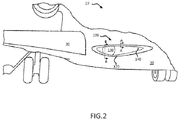
FIG. 2 illustrates a perspective view of a portion of aircraft, in accordance with various embodiments; -
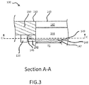
FIG. 3 illustrates a cross-section A-A of a portion of halo light assembly fromFIG. 2 , in accordance with various embodiments; -
FIG. 4 illustrates a cross-section B-B of section of a portion of halo light assembly ofFIG. 2 , in accordance with various embodiments; -
FIG. 5 illustrates a cross-section of section C-C of section of a portion of halo light assembly ofFIG. 2 , in accordance with various embodiments; and -
FIG. 6 illustrates a method of producing a halo effect on a halo light assembly for an aircraft, in accordance with various embodiments. - All ranges and ratio limits disclosed herein may be combined. It is to be understood that unless specifically stated otherwise, references to "a," "an," and/or "the" may include one or more than one and that reference to an item in the singular may also include the item in the plural.
- The detailed description of exemplary embodiments herein makes reference to the accompanying drawings, which show exemplary embodiments by way of illustration. While these exemplary embodiments are described in sufficient detail to enable those skilled in the art to practice the exemplary embodiments of the disclosure, it should be understood that other embodiments may be realized and that logical changes and adaptations in design and construction may be made in accordance with this disclosure and the teachings herein. Thus, the detailed description herein is presented for purposes of illustration only and not limitation.
- The scope of the disclosure is defined by the appended claims rather than by merely the examples described. For example, the steps recited in any of the method or process descriptions may be executed in any order and are not necessarily limited to the order presented. Furthermore, any reference to singular includes plural embodiments, and any reference to more than one component or step may include a singular embodiment or step. Also, any reference to attached, fixed, coupled, connected or the like may include permanent, removable, temporary, partial, full and/or any other possible attachment option. Additionally, any reference to without contact (or similar phrases) may also include reduced contact or minimal contact. Surface shading lines may be used throughout the figures to denote different parts but not necessarily to denote the same or different materials. As used herein, "forward" refers to the direction associated with a nose (e.g., the front end) of the aircraft, or generally, to the direction of flight or motion.
- With reference to
FIG. 1 , anaircraft 10 in accordance with various embodiments may comprise aircraft systems, for example, one or more landing gear such aslanding gear 12, which may generally supportaircraft 10 when aircraft is not flying, allowingaircraft 10 to taxi, take off, and land without damage.Aircraft 10 may include one or moreexterior lamps 14 such as, for example,landing lights 16, taxi lights 17, andnavigation lights 18.Aircraft 10 may include any number of otherexterior lamps 14 such as logo lights, runway turnoff lights, engine scan lights, anti-collision lights, strobe lights, beacon lights, cargo compartment lights, obstruction lights, landing gear lights, and/or the like. - With reference now to
FIG. 2 , a perspective view of a portion ofaircraft 10, in accordance with various embodiments, is illustrated.Aircraft 10 may include ahalo light assembly 100 disposed onfuselage 20 proximate awing 30. Although illustrated atfuselage 20proximate wing 30, thehalo light assembly 100 may be disposed in any location on aircraft 10 (e.g.,exterior lamps 14 locations fromFIG. 1 ). Thehalo light assembly 100 may comprise ahalo portion 120 and amain light portion 130. Thehalo portion 120 may be configured to provide a halo effect of thehalo light assembly 100. A "halo effect," as disclosed herein refers to a glow (i.e., light emission, reflection, refraction or dispersion) disposed around or substantially around a perimeter of thehalo light assembly 100. Thehalo portion 120 and themain light portion 130 may be enclosed by alaminate transparency 140. Thelaminate transparency 140 may comprise any material known in the art, such as poly (methyl methacrylate) ("PMMA"), or the like. - Referring now to
FIG. 3 , a cross-section A-A of a portion of halolight assembly 100 is illustrated, in accordance with various embodiments. The halolight assembly 100 may comprise a secondarylight source 110 and abevel 150. The secondarylight source 110 may be coupled to thebevel 150 by any method known in the art, such as fasteners, adhesives, or the like. In various embodiments, the secondarylight source 110 be embedded inbevel 150. The secondarylight source 110 may be directed towards thelaminate transparency 140. The secondarylight source 110 may be configured to illuminate an area forward ofaircraft 10. The secondarylight source 110 may be configured to create a halo effect for the halo portion 120 (fromFIG. 2 ) of the halolight assembly 100. The secondarylight source 110 may be any light source known in the art, such as a light emitting diode (LED), or the like. - In various embodiments, the
laminate transparency 140 comprises afirst laminate layer 142 disposed adjacent to bevel 150. In various embodiments,bevel 150 may be coupled tofuselage 20 and/orwing 30 fromFIG. 2 . In various embodiments,bevel 150 may be integral tofuselage 20 and /orwing 30 fromFIG. 2 . "Integral," as referred to herein refers to a monolithic component (i.e., a component manufactured out of a single material).First laminate layer 142 may include anexternal surface 143 exposed to an external environment (e.g., atmosphere, or the like).External surface 143 may be disposed adjacent to a bevelexternal surface 153. Thelaminate transparency 140 may further comprise a second laminate later 144 disposed inward from first laminate later 142. Thelaminate transparency 140 may further comprise adiffusion layer 146. Thediffusion layer 146 may be disposed on aninternal surface 149 of thesecond laminate layer 144. - In various embodiments, the
diffusion layer 146 may comprise a diffusion paint, a textured surface, or the like. A textured surface may comprise a rough finish of an internal surface ofsecond laminate layer 144. A diffusion paint may include a white matte paint, white gloss paint, an opaque pain (white or colored depending on desired effect), a particular unique pattern such that it illuminates this pattern so it is visible from a distance at night (rather than a solid stripe), or the like. The diffusion paint may be configured to reflect some light and/or diffuse some light. Thediffusion layer 146 may be configured to reflect light emitted from the secondarylight source 110 outward towardsexternal surface 143 of thefirst laminate layer 142. Thediffusion layer 146 may be configured to provide a halo effect at thehalo portion 120 fromFIG. 1 . In various embodiments, a thickness T1 of thehalo portion 120 may correspond to afirst portion 147 ofdiffusion layer 146 disposed oppositeexternal surface 143 of thefirst laminate layer 142. In various embodiments, thediffusion layer 146 may be disposed at any location on an internal surface ofsecond laminate layer 144 where a halo effect is desired. - In various embodiments, the
first laminate layer 142 may comprise any laminate transparency known in the art. In various embodiments, thefirst laminate layer 142 comprises PMMA. Thesecond laminate layer 144 may also comprise any laminate transparency known in the art. In various embodiments, thesecond laminate layer 144 comprise polycarbonate, or the like. Thesecond laminate layer 144 may be configured to act as a light pipe. Thefirst laminate layer 142 may be configured for abrasion resistance. Thesecond laminate layer 144 may be configured for impact resistance. For example,first laminate layer 142 may comprise a first index of refraction andsecond laminate layer 144 may comprise a second index of refraction. The second index of refraction of thesecond laminate layer 144 may be greater than a first index of refraction of thefirst laminate layer 142. In various embodiments, the halolight assembly 100 may be configured not to illuminate any abrasion onexternal surface 143 due to the difference in the index of refraction. - Although illustrated with a
first laminate layer 142 and asecond laminate layer 144, one skilled in the art would recognize that thefirst laminate layer 142 and thesecond laminate layer 144 may comprise a single laminate layer (e.g., a PMMA layer, a polycarbonate layer, or the like). - In various embodiments, secondary
light source 110 extends around a perimeter of an adjacentoutward surface 145 ofsecond laminate layer 144. With reference now toFIG. 4 , a cross-section of section B-B ofFIG. 2 is illustrated, in accordance with various embodiments. In various embodiments, thelaminate transparency 140 is surrounded by and enclosed by thebevel 150. The bevel may comprise any material known in the art, such as aluminum or the like. The halolight assembly 100 may further comprise a mainlight source 160 disposed inward to secondarylight source 110. The mainlight source 160 may comprise any light source known in the art, such as an LED, or the like. The mainlight source 160 may be disposed adjacent to thesecond laminate layer 144. Thesecond laminate layer 144 may be disposed between thefirst laminate layer 142 and the mainlight source 160. The main light source may further be directed towards aninternal surface 149 ofsecond laminate layer 144. In various embodiments,internal surface 149 may be a non-diffusion layer. In various embodiments, the mainlight source 160 may be configured to emit light forward ofaircraft 10 fromFIG. 1 through thefirst laminate layer 142 and thesecond laminate layer 144. - In various embodiments, the
bevel 150 may define anaperture 152 disposed therein. Thelaminate transparency 140 may be disposed within theaperture 152. Theaperture 152 may define aninner surface 154. Thelaminate transparency 140 may abut theinner surface 154 of theaperture 152. - With reference now to
FIG. 5 , a cross-section of section C-C ofFIG. 3 is illustrated, in accordance with various embodiments. In various embodiments, secondarylight source 110 extends around an entire perimeter ofsecond laminate layer 144. The secondarylight source 110 may comprise a flexible strip 112 extending completely around theoutward surface 145 ofsecond laminate layer 144. The secondarylight source 110 may further comprise a plurality of lights 114 (e.g., LED lights) embedded in the flexible strip 112. Each light in the plurality of lights 114 may be disposed proximate theoutward surface 145 ofsecond laminate layer 144. Each light in the plurality of lights 114 may be oriented inward toward theoutward surface 145 of second laminate layer. Each light in the plurality of lights 114 may be configured to emit light into thesecond laminate layer 144. In various embodiments, the flexible strip 112 may comprise any material known in the art, such as plastic, or the like. - With combined reference now to
FIGs. 3 and4 , aninward edge 148 ofdiffusion layer 146 may partially define the thickness T1 ofhalo portion 120.Inward edge 148 is shown as a hidden line inFIG. 4 as inward edge would be disposed behindsecond laminate layer 144 along section line C-C. Thediffusion layer 146 may reflect light towardexternal surface 143 and partially definehalo portion 120. As light extends further inward, mainlight portion 130 may be configured to illuminate an area external toexternal surface 143 of thefirst laminate layer 142. - Referring now to
FIG. 6 , amethod 600 of producing a halo effect on a halolight assembly 100 for anaircraft 10 is illustrated. The method may comprise emitting light inward towards a laminate transparency 140 (step 602). Thelaminate transparency 140 may comprise afirst laminate layer 142, asecond laminate layer 144 and adiffusion layer 146. The light may be emitted inward from an outer perimeter of thelaminate transparency 140. The light may be directed into thesecond laminate layer 144. Thesecond laminate layer 144 may be disposed between thefirst laminate layer 142 and thediffusion layer 146. - In various embodiments, the
method 600 may further comprise reflecting the light off of thediffusion layer 146. Thediffusion layer 146 may be a coating, an internal textured surface of thesecond laminate layer 144, or the like. Themethod 600 may further comprise directing the light external to an aircraft 10 (step 606). The light may be directed external to the aircraft over the length of thediffusion layer 146 disposed opposite anexternal surface 143 of the first laminate layer. The light may produce a halo effect around a perimeter of a halolight assembly 100. - Benefits and other advantages have been described herein with regard to specific embodiments. Furthermore, the connecting lines shown in the various figures contained herein are intended to represent exemplary functional relationships and/or physical couplings between the various elements. It should be noted that many alternative or additional functional relationships or physical connections may be present in a practical system. However, the benefits, advantages, and any elements that may cause any benefit or advantage to occur or become more pronounced are not to be construed as critical, required, or essential features or elements of the disclosure. The scope of the disclosure is accordingly to be limited by nothing other than the appended claims, in which reference to an element in the singular is not intended to mean "one and only one" unless explicitly so stated, but rather "one or more." Moreover, where a phrase similar to "at least one of A, B, or C" is used in the claims, it is intended that the phrase be interpreted to mean that A alone may be present in an embodiment, B alone may be present in an embodiment, C alone may be present in an embodiment, or that any combination of the elements A, B and C may be present in a single embodiment; for example, A and B, A and C, B and C, or A and B and C.
- Systems, methods and apparatus are provided herein. In the detailed description herein, references to "various embodiments," "one embodiment," "an embodiment," "an example embodiment," etc., indicate that the embodiment described may include a particular feature, structure, or characteristic, but every embodiment may not necessarily include the particular feature, structure, or characteristic. Moreover, such phrases are not necessarily referring to the same embodiment. Further, when a particular feature, structure, or characteristic is described in connection with an embodiment, it is submitted that it is within the knowledge of one skilled in the art to affect such feature, structure, or characteristic in connection with other embodiments whether or not explicitly described. After reading the description, it will be apparent to one skilled in the relevant art(s) how to implement the disclosure in alternative embodiments.
Claims (15)
- A halo light assembly, comprising:a bevel (150) including an aperture (152) defining an inner surface (154);a laminate transparency (140) coupled to the bevel, the laminate transparency disposed in the aperture, the laminate transparency configured to abut the bevel, the laminate transparency including an internal surface (149), an external surface (143), and a diffusion layer (146), the diffusion layer disposed on the internal surface of the laminate transparency; anda light source (110) coupled to the bevel and disposed adjacent to the laminate transparency, the light source extending around a perimeter of the laminate transparency, the light source oriented inward toward the laminate transparency.
- The halo light assembly of claim 1, wherein the light source comprises a flexible strip (112) and a plurality of lights (114), and optionally wherein the plurality of lights are embedded in the flexible strip.
- The halo light assembly of claim 1 or 2, wherein the laminate transparency further comprises a first laminate layer (142) and a second laminate layer (144), the second laminate layer disposed between the diffusion layer and the first laminate layer, and optionally wherein a second index of refraction of the second laminate layer is greater than a first index of refraction of the first laminate layer.
- The halo light assembly of claim 3, wherein the light source is oriented towards the second laminate layer.
- The halo light assembly of claim 3 or 4, further comprising a main light source (160), wherein the second laminate layer is disposed between the first laminate layer and the main light source.
- The halo light assembly of any preceding claim, wherein the diffusion layer extends from an outer edge of the internal surface of the laminate transparency inward on the internal surface.
- The halo light assembly of any preceding claim, wherein the diffusion layer extends around a perimeter of the halo light assembly on the internal surface of the laminate transparency.
- An aircraft, comprising:a fuselage (20);a wing (30) extending from the fuselage;a halo light assembly (100) disposed on at least one of the fuselage or the wing, the halo light assembly comprising:a bevel (150) including an aperture (152) defining an inner surface (154);a laminate transparency (140) coupled to the bevel, the laminate transparency disposed in the aperture, the laminate transparency including an internal surface (149), an external surface (143), and a diffusion layer (146), the diffusion layer disposed on the internal surface of the laminate transparency;a main light source (160) disposed internal to the laminate transparency; anda secondary light source (110) coupled to the bevel and disposed adjacent to the laminate transparency, the secondary light source configured to produce a halo effect in the halo light assembly.
- The aircraft of claim 8, wherein the secondary light source extends around a perimeter of the laminate transparency, the secondary light source oriented inward toward the laminate transparency.
- The aircraft of claim 9, wherein the secondary light source comprises a flexible strip (112) and a plurality of lights (114), and optionally wherein the plurality of lights are embedded in the flexible strip.
- The aircraft of claim 8, 9 or 10, wherein the diffusion layer comprises at least one of a textured surface or a diffusion paint.
- The aircraft of any of claims 8 to 11, wherein the laminate transparency further comprises a first laminate layer (142) and a second laminate layer (144), the second laminate layer disposed between the diffusion layer and the first laminate layer, and optionally wherein a second index of refraction of the second laminate layer is greater than a first index of refraction of the first laminate layer.
- The aircraft of claim 12, wherein the secondary light source is oriented towards the second laminate layer, and/or wherein the second laminate layer is disposed between the first laminate layer and the main light source.
- A method of producing a halo effect for a halo light assembly, the method comprising:emitting a light inward towards a laminate transparency, the laminate transparency comprising a diffusion layer disposed on an internal surface of the laminate transparency;reflecting the light off the diffusion layer; anddeflecting the light external to the halo light assembly.
- The method of claim 14, wherein the laminate transparency comprises a first laminate layer and a second laminate layer, the second laminate layer disposed between the diffusion layer and the first laminate layer, and wherein the emitting the light further comprises emitting the light towards the second laminate layer.
Applications Claiming Priority (1)
| Application Number | Priority Date | Filing Date | Title |
|---|---|---|---|
| US16/746,280 US10894614B1 (en) | 2020-01-17 | 2020-01-17 | Halo light assembly |
Publications (2)
| Publication Number | Publication Date |
|---|---|
| EP3851382A1 true EP3851382A1 (en) | 2021-07-21 |
| EP3851382B1 EP3851382B1 (en) | 2024-08-28 |
Family
ID=74180466
Family Applications (1)
| Application Number | Title | Priority Date | Filing Date |
|---|---|---|---|
| EP21152178.6A Active EP3851382B1 (en) | 2020-01-17 | 2021-01-18 | Halo light assembly |
Country Status (2)
| Country | Link |
|---|---|
| US (1) | US10894614B1 (en) |
| EP (1) | EP3851382B1 (en) |
Citations (10)
| Publication number | Priority date | Publication date | Assignee | Title |
|---|---|---|---|---|
| US6007209A (en) * | 1997-03-19 | 1999-12-28 | Teledyne Industries, Inc. | Light source for backlighting |
| WO2004114342A1 (en) * | 2003-06-26 | 2004-12-29 | Ekolite Co., Inc | An indicator displaying the electrical appliances performance and preparation method thereof |
| EP1615820A1 (en) * | 2003-04-04 | 2006-01-18 | Honeywell International Inc. | Led based light guide for aircraft formation lighting |
| US20070006493A1 (en) * | 2003-05-12 | 2007-01-11 | Arnold Eberwein | Illuminated license plate for vehicles and vehicle provided with the same |
| US20100107463A1 (en) * | 2008-10-03 | 2010-05-06 | Tracer Image | Illuminated signboard with edge effect |
| US20120106198A1 (en) * | 2010-10-27 | 2012-05-03 | Young Lighting Technology Corporation | Flat light source module |
| CN102720971A (en) * | 2012-06-28 | 2012-10-10 | 苏州向隆塑胶有限公司 | Lighting device |
| US20120320621A1 (en) * | 2010-01-26 | 2012-12-20 | Saint-Gobain Glass France | Luminous vehicle glazing and manufacture thereof |
| US20160085012A1 (en) * | 2014-09-22 | 2016-03-24 | Douglas Allen Pfau | Gradient light halo for a remote input device |
| EP3382264A1 (en) * | 2017-03-31 | 2018-10-03 | Everlight Electronics Co., Ltd. | Light emitting apparatus and lighting module |
Family Cites Families (8)
| Publication number | Priority date | Publication date | Assignee | Title |
|---|---|---|---|---|
| US6092915A (en) | 1998-01-30 | 2000-07-25 | The Boeing Company | Decorative lighting laminate |
| US6526681B1 (en) * | 1999-03-26 | 2003-03-04 | Javier A. G. De Saro | Sign for illumination utilizing translucent layers |
| US6808804B2 (en) | 2000-08-18 | 2004-10-26 | Teijin Chemicals, Ltd. | Sheet-form layered structure with attractive appearance and utilization thereof |
| JP5020561B2 (en) | 2006-07-25 | 2012-09-05 | ナガシマ工芸株式会社 | Backlight pseudo inlay decoration |
| EP2321677A4 (en) | 2008-08-08 | 2011-08-17 | 3M Innovative Properties Co | Lightguide having a viscoelastic layer for managing light |
| EP2734995B1 (en) * | 2011-07-27 | 2017-11-29 | Grote Industries, LLC | Method and system for flexible illuminated devices having edge lighting utilizing light active sheet material with integrated light emitting diode |
| CN202733542U (en) * | 2012-07-30 | 2013-02-13 | 苏州茂立光电科技有限公司 | Lighting device |
| US9772439B2 (en) * | 2016-02-05 | 2017-09-26 | Sharp Kabushiki Kaisha | Thin backlight with reduced bezel width |
-
2020
- 2020-01-17 US US16/746,280 patent/US10894614B1/en active Active
-
2021
- 2021-01-18 EP EP21152178.6A patent/EP3851382B1/en active Active
Patent Citations (10)
| Publication number | Priority date | Publication date | Assignee | Title |
|---|---|---|---|---|
| US6007209A (en) * | 1997-03-19 | 1999-12-28 | Teledyne Industries, Inc. | Light source for backlighting |
| EP1615820A1 (en) * | 2003-04-04 | 2006-01-18 | Honeywell International Inc. | Led based light guide for aircraft formation lighting |
| US20070006493A1 (en) * | 2003-05-12 | 2007-01-11 | Arnold Eberwein | Illuminated license plate for vehicles and vehicle provided with the same |
| WO2004114342A1 (en) * | 2003-06-26 | 2004-12-29 | Ekolite Co., Inc | An indicator displaying the electrical appliances performance and preparation method thereof |
| US20100107463A1 (en) * | 2008-10-03 | 2010-05-06 | Tracer Image | Illuminated signboard with edge effect |
| US20120320621A1 (en) * | 2010-01-26 | 2012-12-20 | Saint-Gobain Glass France | Luminous vehicle glazing and manufacture thereof |
| US20120106198A1 (en) * | 2010-10-27 | 2012-05-03 | Young Lighting Technology Corporation | Flat light source module |
| CN102720971A (en) * | 2012-06-28 | 2012-10-10 | 苏州向隆塑胶有限公司 | Lighting device |
| US20160085012A1 (en) * | 2014-09-22 | 2016-03-24 | Douglas Allen Pfau | Gradient light halo for a remote input device |
| EP3382264A1 (en) * | 2017-03-31 | 2018-10-03 | Everlight Electronics Co., Ltd. | Light emitting apparatus and lighting module |
Also Published As
| Publication number | Publication date |
|---|---|
| US10894614B1 (en) | 2021-01-19 |
| EP3851382B1 (en) | 2024-08-28 |
Similar Documents
| Publication | Publication Date | Title |
|---|---|---|
| EP2855275B1 (en) | Lighting array for an aircraft | |
| US11479366B2 (en) | Exterior aircraft light, aircraft comprising the same, and method of operating an exterior aircraft light | |
| US7717593B2 (en) | Device for improved illumination efficiency | |
| US7278766B2 (en) | LED based light guide for dual mode aircraft formation lighting | |
| US20190382132A1 (en) | Aircraft beacon light and aircraft comprising an aircraft beacon light | |
| US8956023B1 (en) | Combined wing scan and winglet illumination light unit and aircraft having winglet illumination | |
| US20190300201A1 (en) | Aircraft wing lighting | |
| CN107757936A (en) | Outside aircraft lamp unit and the method for warning ground staff | |
| EP1510457A3 (en) | Anti collision light for aircraft | |
| CN107128499B (en) | Vehicle cabin path finding assembly | |
| JP2020513208A (en) | Projection on the outer surface of the aircraft body | |
| GB2553524A (en) | Wing tip device | |
| US8245973B2 (en) | Methods and systems for improving aircraft visibility | |
| EP3851382B1 (en) | Halo light assembly | |
| US10773826B1 (en) | Adjustable aiming aircraft light assembly | |
| US12000581B1 (en) | Exterior decorative lighting | |
| US10730639B2 (en) | Aircraft vertical stabilizer illumination light and aircraft comprising the same | |
| EP3812286B1 (en) | Anti-collision light assembly | |
| GB2540264A (en) | Navigation lights | |
| EP4378835B1 (en) | Exterior decorative lighting | |
| US20260138753A1 (en) | Aircraft with retroreflective surfaces | |
| AU595628B2 (en) | Aircraft tanker trailing edge lights | |
| EP4491521A1 (en) | Aircraft light, aircraft comprising an aircraft light and method of manufacturing an aircraft light |
Legal Events
| Date | Code | Title | Description |
|---|---|---|---|
| PUAI | Public reference made under article 153(3) epc to a published international application that has entered the european phase |
Free format text: ORIGINAL CODE: 0009012 |
|
| STAA | Information on the status of an ep patent application or granted ep patent |
Free format text: STATUS: THE APPLICATION HAS BEEN PUBLISHED |
|
| AK | Designated contracting states |
Kind code of ref document: A1 Designated state(s): AL AT BE BG CH CY CZ DE DK EE ES FI FR GB GR HR HU IE IS IT LI LT LU LV MC MK MT NL NO PL PT RO RS SE SI SK SM TR |
|
| STAA | Information on the status of an ep patent application or granted ep patent |
Free format text: STATUS: REQUEST FOR EXAMINATION WAS MADE |
|
| 17P | Request for examination filed |
Effective date: 20220121 |
|
| RBV | Designated contracting states (corrected) |
Designated state(s): AL AT BE BG CH CY CZ DE DK EE ES FI FR GB GR HR HU IE IS IT LI LT LU LV MC MK MT NL NO PL PT RO RS SE SI SK SM TR |
|
| STAA | Information on the status of an ep patent application or granted ep patent |
Free format text: STATUS: EXAMINATION IS IN PROGRESS |
|
| 17Q | First examination report despatched |
Effective date: 20230118 |
|
| P01 | Opt-out of the competence of the unified patent court (upc) registered |
Effective date: 20230922 |
|
| GRAP | Despatch of communication of intention to grant a patent |
Free format text: ORIGINAL CODE: EPIDOSNIGR1 |
|
| STAA | Information on the status of an ep patent application or granted ep patent |
Free format text: STATUS: GRANT OF PATENT IS INTENDED |
|
| RIC1 | Information provided on ipc code assigned before grant |
Ipc: F21W 107/30 20180101ALN20240307BHEP Ipc: B64D 47/04 20060101AFI20240307BHEP |
|
| INTG | Intention to grant announced |
Effective date: 20240404 |
|
| GRAS | Grant fee paid |
Free format text: ORIGINAL CODE: EPIDOSNIGR3 |
|
| GRAA | (expected) grant |
Free format text: ORIGINAL CODE: 0009210 |
|
| STAA | Information on the status of an ep patent application or granted ep patent |
Free format text: STATUS: THE PATENT HAS BEEN GRANTED |
|
| AK | Designated contracting states |
Kind code of ref document: B1 Designated state(s): AL AT BE BG CH CY CZ DE DK EE ES FI FR GB GR HR HU IE IS IT LI LT LU LV MC MK MT NL NO PL PT RO RS SE SI SK SM TR |
|
| REG | Reference to a national code |
Ref country code: CH Ref legal event code: EP |
|
| REG | Reference to a national code |
Ref country code: DE Ref legal event code: R096 Ref document number: 602021017720 Country of ref document: DE |
|
| REG | Reference to a national code |
Ref country code: IE Ref legal event code: FG4D |
|
| REG | Reference to a national code |
Ref country code: LT Ref legal event code: MG9D |
|
| PG25 | Lapsed in a contracting state [announced via postgrant information from national office to epo] |
Ref country code: NO Free format text: LAPSE BECAUSE OF FAILURE TO SUBMIT A TRANSLATION OF THE DESCRIPTION OR TO PAY THE FEE WITHIN THE PRESCRIBED TIME-LIMIT Effective date: 20241128 |
|
| REG | Reference to a national code |
Ref country code: AT Ref legal event code: MK05 Ref document number: 1717717 Country of ref document: AT Kind code of ref document: T Effective date: 20240828 |
|
| PG25 | Lapsed in a contracting state [announced via postgrant information from national office to epo] |
Ref country code: NL Free format text: LAPSE BECAUSE OF FAILURE TO SUBMIT A TRANSLATION OF THE DESCRIPTION OR TO PAY THE FEE WITHIN THE PRESCRIBED TIME-LIMIT Effective date: 20240828 Ref country code: PT Free format text: LAPSE BECAUSE OF FAILURE TO SUBMIT A TRANSLATION OF THE DESCRIPTION OR TO PAY THE FEE WITHIN THE PRESCRIBED TIME-LIMIT Effective date: 20241230 Ref country code: GR Free format text: LAPSE BECAUSE OF FAILURE TO SUBMIT A TRANSLATION OF THE DESCRIPTION OR TO PAY THE FEE WITHIN THE PRESCRIBED TIME-LIMIT Effective date: 20241129 Ref country code: PL Free format text: LAPSE BECAUSE OF FAILURE TO SUBMIT A TRANSLATION OF THE DESCRIPTION OR TO PAY THE FEE WITHIN THE PRESCRIBED TIME-LIMIT Effective date: 20240828 Ref country code: FI Free format text: LAPSE BECAUSE OF FAILURE TO SUBMIT A TRANSLATION OF THE DESCRIPTION OR TO PAY THE FEE WITHIN THE PRESCRIBED TIME-LIMIT Effective date: 20240828 |
|
| PG25 | Lapsed in a contracting state [announced via postgrant information from national office to epo] |
Ref country code: BG Free format text: LAPSE BECAUSE OF FAILURE TO SUBMIT A TRANSLATION OF THE DESCRIPTION OR TO PAY THE FEE WITHIN THE PRESCRIBED TIME-LIMIT Effective date: 20240828 |
|
| PG25 | Lapsed in a contracting state [announced via postgrant information from national office to epo] |
Ref country code: LV Free format text: LAPSE BECAUSE OF FAILURE TO SUBMIT A TRANSLATION OF THE DESCRIPTION OR TO PAY THE FEE WITHIN THE PRESCRIBED TIME-LIMIT Effective date: 20240828 |
|
| REG | Reference to a national code |
Ref country code: NL Ref legal event code: MP Effective date: 20240828 |
|
| PG25 | Lapsed in a contracting state [announced via postgrant information from national office to epo] |
Ref country code: AT Free format text: LAPSE BECAUSE OF FAILURE TO SUBMIT A TRANSLATION OF THE DESCRIPTION OR TO PAY THE FEE WITHIN THE PRESCRIBED TIME-LIMIT Effective date: 20240828 Ref country code: IS Free format text: LAPSE BECAUSE OF FAILURE TO SUBMIT A TRANSLATION OF THE DESCRIPTION OR TO PAY THE FEE WITHIN THE PRESCRIBED TIME-LIMIT Effective date: 20241228 |
|
| PG25 | Lapsed in a contracting state [announced via postgrant information from national office to epo] |
Ref country code: HR Free format text: LAPSE BECAUSE OF FAILURE TO SUBMIT A TRANSLATION OF THE DESCRIPTION OR TO PAY THE FEE WITHIN THE PRESCRIBED TIME-LIMIT Effective date: 20240828 |
|
| PG25 | Lapsed in a contracting state [announced via postgrant information from national office to epo] |
Ref country code: RS Free format text: LAPSE BECAUSE OF FAILURE TO SUBMIT A TRANSLATION OF THE DESCRIPTION OR TO PAY THE FEE WITHIN THE PRESCRIBED TIME-LIMIT Effective date: 20241128 Ref country code: ES Free format text: LAPSE BECAUSE OF FAILURE TO SUBMIT A TRANSLATION OF THE DESCRIPTION OR TO PAY THE FEE WITHIN THE PRESCRIBED TIME-LIMIT Effective date: 20240828 |
|
| PG25 | Lapsed in a contracting state [announced via postgrant information from national office to epo] |
Ref country code: RS Free format text: LAPSE BECAUSE OF FAILURE TO SUBMIT A TRANSLATION OF THE DESCRIPTION OR TO PAY THE FEE WITHIN THE PRESCRIBED TIME-LIMIT Effective date: 20241128 Ref country code: PT Free format text: LAPSE BECAUSE OF FAILURE TO SUBMIT A TRANSLATION OF THE DESCRIPTION OR TO PAY THE FEE WITHIN THE PRESCRIBED TIME-LIMIT Effective date: 20241230 Ref country code: PL Free format text: LAPSE BECAUSE OF FAILURE TO SUBMIT A TRANSLATION OF THE DESCRIPTION OR TO PAY THE FEE WITHIN THE PRESCRIBED TIME-LIMIT Effective date: 20240828 Ref country code: NO Free format text: LAPSE BECAUSE OF FAILURE TO SUBMIT A TRANSLATION OF THE DESCRIPTION OR TO PAY THE FEE WITHIN THE PRESCRIBED TIME-LIMIT Effective date: 20241128 Ref country code: NL Free format text: LAPSE BECAUSE OF FAILURE TO SUBMIT A TRANSLATION OF THE DESCRIPTION OR TO PAY THE FEE WITHIN THE PRESCRIBED TIME-LIMIT Effective date: 20240828 Ref country code: LV Free format text: LAPSE BECAUSE OF FAILURE TO SUBMIT A TRANSLATION OF THE DESCRIPTION OR TO PAY THE FEE WITHIN THE PRESCRIBED TIME-LIMIT Effective date: 20240828 Ref country code: IS Free format text: LAPSE BECAUSE OF FAILURE TO SUBMIT A TRANSLATION OF THE DESCRIPTION OR TO PAY THE FEE WITHIN THE PRESCRIBED TIME-LIMIT Effective date: 20241228 Ref country code: HR Free format text: LAPSE BECAUSE OF FAILURE TO SUBMIT A TRANSLATION OF THE DESCRIPTION OR TO PAY THE FEE WITHIN THE PRESCRIBED TIME-LIMIT Effective date: 20240828 Ref country code: GR Free format text: LAPSE BECAUSE OF FAILURE TO SUBMIT A TRANSLATION OF THE DESCRIPTION OR TO PAY THE FEE WITHIN THE PRESCRIBED TIME-LIMIT Effective date: 20241129 Ref country code: FI Free format text: LAPSE BECAUSE OF FAILURE TO SUBMIT A TRANSLATION OF THE DESCRIPTION OR TO PAY THE FEE WITHIN THE PRESCRIBED TIME-LIMIT Effective date: 20240828 Ref country code: ES Free format text: LAPSE BECAUSE OF FAILURE TO SUBMIT A TRANSLATION OF THE DESCRIPTION OR TO PAY THE FEE WITHIN THE PRESCRIBED TIME-LIMIT Effective date: 20240828 Ref country code: BG Free format text: LAPSE BECAUSE OF FAILURE TO SUBMIT A TRANSLATION OF THE DESCRIPTION OR TO PAY THE FEE WITHIN THE PRESCRIBED TIME-LIMIT Effective date: 20240828 Ref country code: AT Free format text: LAPSE BECAUSE OF FAILURE TO SUBMIT A TRANSLATION OF THE DESCRIPTION OR TO PAY THE FEE WITHIN THE PRESCRIBED TIME-LIMIT Effective date: 20240828 |
|
| PG25 | Lapsed in a contracting state [announced via postgrant information from national office to epo] |
Ref country code: RO Free format text: LAPSE BECAUSE OF FAILURE TO SUBMIT A TRANSLATION OF THE DESCRIPTION OR TO PAY THE FEE WITHIN THE PRESCRIBED TIME-LIMIT Effective date: 20240828 Ref country code: DK Free format text: LAPSE BECAUSE OF FAILURE TO SUBMIT A TRANSLATION OF THE DESCRIPTION OR TO PAY THE FEE WITHIN THE PRESCRIBED TIME-LIMIT Effective date: 20240828 Ref country code: SM Free format text: LAPSE BECAUSE OF FAILURE TO SUBMIT A TRANSLATION OF THE DESCRIPTION OR TO PAY THE FEE WITHIN THE PRESCRIBED TIME-LIMIT Effective date: 20240828 |
|
| PG25 | Lapsed in a contracting state [announced via postgrant information from national office to epo] |
Ref country code: EE Free format text: LAPSE BECAUSE OF FAILURE TO SUBMIT A TRANSLATION OF THE DESCRIPTION OR TO PAY THE FEE WITHIN THE PRESCRIBED TIME-LIMIT Effective date: 20240828 |
|
| PG25 | Lapsed in a contracting state [announced via postgrant information from national office to epo] |
Ref country code: CZ Free format text: LAPSE BECAUSE OF FAILURE TO SUBMIT A TRANSLATION OF THE DESCRIPTION OR TO PAY THE FEE WITHIN THE PRESCRIBED TIME-LIMIT Effective date: 20240828 |
|
| PG25 | Lapsed in a contracting state [announced via postgrant information from national office to epo] |
Ref country code: IT Free format text: LAPSE BECAUSE OF FAILURE TO SUBMIT A TRANSLATION OF THE DESCRIPTION OR TO PAY THE FEE WITHIN THE PRESCRIBED TIME-LIMIT Effective date: 20240828 Ref country code: SK Free format text: LAPSE BECAUSE OF FAILURE TO SUBMIT A TRANSLATION OF THE DESCRIPTION OR TO PAY THE FEE WITHIN THE PRESCRIBED TIME-LIMIT Effective date: 20240828 |
|
| REG | Reference to a national code |
Ref country code: DE Ref legal event code: R097 Ref document number: 602021017720 Country of ref document: DE |
|
| PLBE | No opposition filed within time limit |
Free format text: ORIGINAL CODE: 0009261 |
|
| STAA | Information on the status of an ep patent application or granted ep patent |
Free format text: STATUS: NO OPPOSITION FILED WITHIN TIME LIMIT |
|
| 26N | No opposition filed |
Effective date: 20250530 |
|
| REG | Reference to a national code |
Ref country code: CH Ref legal event code: PL |
|
| PG25 | Lapsed in a contracting state [announced via postgrant information from national office to epo] |
Ref country code: SE Free format text: LAPSE BECAUSE OF FAILURE TO SUBMIT A TRANSLATION OF THE DESCRIPTION OR TO PAY THE FEE WITHIN THE PRESCRIBED TIME-LIMIT Effective date: 20240828 |
|
| PG25 | Lapsed in a contracting state [announced via postgrant information from national office to epo] |
Ref country code: LU Free format text: LAPSE BECAUSE OF NON-PAYMENT OF DUE FEES Effective date: 20250118 Ref country code: MC Free format text: LAPSE BECAUSE OF FAILURE TO SUBMIT A TRANSLATION OF THE DESCRIPTION OR TO PAY THE FEE WITHIN THE PRESCRIBED TIME-LIMIT Effective date: 20240828 |
|
| PG25 | Lapsed in a contracting state [announced via postgrant information from national office to epo] |
Ref country code: BE Free format text: LAPSE BECAUSE OF NON-PAYMENT OF DUE FEES Effective date: 20250131 |
|
| PG25 | Lapsed in a contracting state [announced via postgrant information from national office to epo] |
Ref country code: CH Free format text: LAPSE BECAUSE OF NON-PAYMENT OF DUE FEES Effective date: 20250131 |
|
| REG | Reference to a national code |
Ref country code: BE Ref legal event code: MM Effective date: 20250131 |
|
| PGFP | Annual fee paid to national office [announced via postgrant information from national office to epo] |
Ref country code: GB Payment date: 20251220 Year of fee payment: 6 |
|
| PGFP | Annual fee paid to national office [announced via postgrant information from national office to epo] |
Ref country code: FR Payment date: 20251217 Year of fee payment: 6 |
|
| PG25 | Lapsed in a contracting state [announced via postgrant information from national office to epo] |
Ref country code: IE Free format text: LAPSE BECAUSE OF NON-PAYMENT OF DUE FEES Effective date: 20250118 |
|
| PGFP | Annual fee paid to national office [announced via postgrant information from national office to epo] |
Ref country code: DE Payment date: 20251217 Year of fee payment: 6 |