EP3851152A1 - Indwelling device - Google Patents
Indwelling device Download PDFInfo
- Publication number
- EP3851152A1 EP3851152A1 EP18933669.6A EP18933669A EP3851152A1 EP 3851152 A1 EP3851152 A1 EP 3851152A1 EP 18933669 A EP18933669 A EP 18933669A EP 3851152 A1 EP3851152 A1 EP 3851152A1
- Authority
- EP
- European Patent Office
- Prior art keywords
- engaging part
- indwelling device
- indwelling
- device body
- distal end
- Prior art date
- Legal status (The legal status is an assumption and is not a legal conclusion. Google has not performed a legal analysis and makes no representation as to the accuracy of the status listed.)
- Withdrawn
Links
Images






Classifications
-
- A—HUMAN NECESSITIES
- A61—MEDICAL OR VETERINARY SCIENCE; HYGIENE
- A61F—FILTERS IMPLANTABLE INTO BLOOD VESSELS; PROSTHESES; DEVICES PROVIDING PATENCY TO, OR PREVENTING COLLAPSING OF, TUBULAR STRUCTURES OF THE BODY, e.g. STENTS; ORTHOPAEDIC, NURSING OR CONTRACEPTIVE DEVICES; FOMENTATION; TREATMENT OR PROTECTION OF EYES OR EARS; BANDAGES, DRESSINGS OR ABSORBENT PADS; FIRST-AID KITS
- A61F2/00—Filters implantable into blood vessels; Prostheses, i.e. artificial substitutes or replacements for parts of the body; Appliances for connecting them with the body; Devices providing patency to, or preventing collapsing of, tubular structures of the body, e.g. stents
- A61F2/82—Devices providing patency to, or preventing collapsing of, tubular structures of the body, e.g. stents
- A61F2/86—Stents in a form characterised by the wire-like elements; Stents in the form characterised by a net-like or mesh-like structure
- A61F2/88—Stents in a form characterised by the wire-like elements; Stents in the form characterised by a net-like or mesh-like structure the wire-like elements formed as helical or spiral coils
-
- A—HUMAN NECESSITIES
- A61—MEDICAL OR VETERINARY SCIENCE; HYGIENE
- A61B—DIAGNOSIS; SURGERY; IDENTIFICATION
- A61B90/00—Instruments, implements or accessories specially adapted for surgery or diagnosis and not covered by any of the groups A61B1/00 - A61B50/00, e.g. for luxation treatment or for protecting wound edges
- A61B90/39—Markers, e.g. radio-opaque or breast lesions markers
-
- A—HUMAN NECESSITIES
- A61—MEDICAL OR VETERINARY SCIENCE; HYGIENE
- A61B—DIAGNOSIS; SURGERY; IDENTIFICATION
- A61B90/00—Instruments, implements or accessories specially adapted for surgery or diagnosis and not covered by any of the groups A61B1/00 - A61B50/00, e.g. for luxation treatment or for protecting wound edges
- A61B90/90—Identification means for patients or instruments, e.g. tags
- A61B90/98—Identification means for patients or instruments, e.g. tags using electromagnetic means, e.g. transponders
-
- A—HUMAN NECESSITIES
- A61—MEDICAL OR VETERINARY SCIENCE; HYGIENE
- A61B—DIAGNOSIS; SURGERY; IDENTIFICATION
- A61B17/00—Surgical instruments, devices or methods
- A61B2017/00831—Material properties
- A61B2017/00867—Material properties shape memory effect
-
- A—HUMAN NECESSITIES
- A61—MEDICAL OR VETERINARY SCIENCE; HYGIENE
- A61B—DIAGNOSIS; SURGERY; IDENTIFICATION
- A61B90/00—Instruments, implements or accessories specially adapted for surgery or diagnosis and not covered by any of the groups A61B1/00 - A61B50/00, e.g. for luxation treatment or for protecting wound edges
- A61B90/03—Automatic limiting or abutting means, e.g. for safety
- A61B2090/033—Abutting means, stops, e.g. abutting on tissue or skin
- A61B2090/036—Abutting means, stops, e.g. abutting on tissue or skin abutting on tissue or skin
-
- A—HUMAN NECESSITIES
- A61—MEDICAL OR VETERINARY SCIENCE; HYGIENE
- A61B—DIAGNOSIS; SURGERY; IDENTIFICATION
- A61B90/00—Instruments, implements or accessories specially adapted for surgery or diagnosis and not covered by any of the groups A61B1/00 - A61B50/00, e.g. for luxation treatment or for protecting wound edges
- A61B90/39—Markers, e.g. radio-opaque or breast lesions markers
- A61B2090/3904—Markers, e.g. radio-opaque or breast lesions markers specially adapted for marking specified tissue
- A61B2090/3912—Body cavities
-
- A—HUMAN NECESSITIES
- A61—MEDICAL OR VETERINARY SCIENCE; HYGIENE
- A61B—DIAGNOSIS; SURGERY; IDENTIFICATION
- A61B90/00—Instruments, implements or accessories specially adapted for surgery or diagnosis and not covered by any of the groups A61B1/00 - A61B50/00, e.g. for luxation treatment or for protecting wound edges
- A61B90/39—Markers, e.g. radio-opaque or breast lesions markers
- A61B2090/397—Markers, e.g. radio-opaque or breast lesions markers electromagnetic other than visible, e.g. microwave
-
- A—HUMAN NECESSITIES
- A61—MEDICAL OR VETERINARY SCIENCE; HYGIENE
- A61B—DIAGNOSIS; SURGERY; IDENTIFICATION
- A61B90/00—Instruments, implements or accessories specially adapted for surgery or diagnosis and not covered by any of the groups A61B1/00 - A61B50/00, e.g. for luxation treatment or for protecting wound edges
- A61B90/39—Markers, e.g. radio-opaque or breast lesions markers
- A61B2090/3987—Applicators for implanting markers
-
- A—HUMAN NECESSITIES
- A61—MEDICAL OR VETERINARY SCIENCE; HYGIENE
- A61B—DIAGNOSIS; SURGERY; IDENTIFICATION
- A61B90/00—Instruments, implements or accessories specially adapted for surgery or diagnosis and not covered by any of the groups A61B1/00 - A61B50/00, e.g. for luxation treatment or for protecting wound edges
- A61B90/39—Markers, e.g. radio-opaque or breast lesions markers
- A61B2090/3991—Markers, e.g. radio-opaque or breast lesions markers having specific anchoring means to fixate the marker to the tissue, e.g. hooks
Definitions
- the present invention relates to an indwelling device that is placed in a patient's body lumen, such as a bronchus of a lung and a blood vessel in a patient.
- RFID radio frequency identifier
- Patent Document 1 describes that a wireless marker is embedded in a lesion in a bronchus of a patient's lung, and, during surgery or the like, a position of a lesion is informed to an operator in real time by wireless communication between a position-specifying system outside of the patient's body and the wireless marker (see FIG. 8 and the like).
- the wireless marker used for this position-specifying system includes a leg (hereinafter referred to as "engagement part") as a mechanism for the wireless marker to be fixed inside the patient's body (see FIG. 13 and the like).
- Patent Literature 1 Japanese Unexamined Patent Application Publication No. 2013-543401
- the conventional wireless marker has had a problem that a hook-shaped proximal end part of an engaging part is likely to damage a patient's bodily wall.
- the conventional wireless marker has had a problem that, due to a relationship between a shape of a wireless marker body and a shape of the engaging part, the wireless marker is likely to occlude a patient's body lumen when disposing the wireless marker in the patient's body lumen.
- the conventional wireless marker has had a problem that the wireless marker is difficult to insert into a catheter lumen and also difficult to carry thereafter because the engaging part is disposed so as to project from a proximal end of the wireless marker toward the proximal end side.
- the conventional wireless marker has had a problem that, since the engaging part is disposed on the proximal end part of the wireless marker, it is not until the whole wireless marker leaves from a distal end of a catheter for conveying the wireless marker that the wireless marker engages with the patient's body lumen, and therefore the wireless marker cannot be swiftly disposed in the patient's body lumen.
- the present invention has been made in response to the aforementioned problems of the prior art, and objects of the present invention is to provide an indwelling device that does not occlude an inside of a body and does not damage a patient's bodily wall, and to provide an indwelling device that can be easily accommodated in a lumen such as a catheter and improves deliverability of the indwelling device, and further to provide an indwelling device that has an engaging part capable of swiftly abutting on the bodily wall and consequently can be swiftly placed in the body.
- the first aspect of the present invention is characterized in that, in an indwelling device including a device body and an engaging part connected to the device body and capable of abutting on a bodily wall, the engaging part can abut on the bodily wall in a state that a region of the engaging part, excluding end parts, is expanded larger than an outer diameter of the device body.
- the second aspect of the present invention is characterized in that, in the indwelling device according to the first aspect, the device body has a small-diameter part having an outer diameter smaller than of other regions, and the engaging part can be stored on the small-diameter part.
- the third aspect of the present invention is characterized in that, in the indwelling device according to the first or second aspect, the engaging part is constructed by spirally winding one or more wires.
- the fourth aspect of the present invention is characterized in that, in the indwelling device according to the third aspect, an end part of the wire on a side not connected to the device body is located on a distal end side in an advancing direction of the indwelling device while being placed in a body.
- the engaging part in the indwelling device including the device body and the engaging part connected to the device body and capable of abutting on the bodily wall, can abut on the bodily wall in a state that the region of the engaging part excluding the end parts is expanded larger than the outer diameter of the device body, and therefore the indwelling device can be securely placed in the body without occluding the inside of the body and damaging the patient's bodily wall.
- the device body has the small-diameter part having the outer diameter smaller than of other regions, and the engaging part can be stored on the small-diameter part, so that not only is the effect of the indwelling device according to the first aspect obtained but the indwelling device also becomes easier to accommodate in a lumen such as a catheter, and deliverability of the indwelling device can be improved.
- the engaging part is constructed by spirally winding one or more wires, and therefore not only is the effect of the indwelling device according to the first or second aspect obtained but an engaging part that exhibits such an effect can also be easily constructed.
- the end part of the wire on the side not connected to the device body is located on the distal end side in the advancing direction of the indwelling device while being placed in a body, and therefore not only is the effect of the indwelling device according to the third aspect obtained but the engaging part can also be swiftly abutted on the bodily wall, and consequently the indwelling device can be swiftly placed in the body.
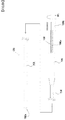
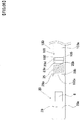
- FIG. 1 is a schematic overall view of a medical appliance for placing an indwelling device according to the first embodiment of the present invention in a body.
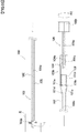
- FIG. 2 is a longitudinal sectional view of FIG. 1 .
- FIG. 3 is a longitudinal sectional view of the medical appliance, illustrating a state that the indwelling device according to the first embodiment is pushed out from the medical appliance.
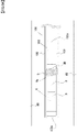
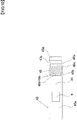
- FIG. 4 is an enlarged sectional view of a part A in FIG. 2 .
- FIG. 5 is an enlarged sectional view of a part B in FIG. 3 .
- a medical appliance 100 for placing an indwelling device 1 (see FIG. 2 to FIG. 5 ) according to the first embodiment described below in a patient's body is composed of a catheter body 102, a connector 104 connected to a proximal end of the catheter body 102, a pusher member 103 slidably inserted into a catheter lumen 105 of the catheter body 102 as well as a distal end-side lumen 101a and an intermediate lumen 101b of the connector 104, and a grip part 106 abutting on a proximal end of the pusher member 103.
- the catheter body 102 is a hollow cylindrical flexible long member and has the catheter lumen 105 inside thereof and an opening 102a on the distal end thereof.
- a material for the catheter body 102 is a resin material made of a biocompatible material.
- Various synthetic resin materials for example, a polyolefin resin such as a polyamide resin, a polyamide elastomer, a polyester, a polyurethane, a polyvinyl chloride resin, a polyethylene, a polypropylene, and an ethylene-propylene copolymer, a fluororesin such as Teflon (registered trademark), an ethylene-vinyl acetate copolymer can be used, and in the first embodiment, a polyamide elastomer is used.
- the pusher member 103 is composed of a solid cylindrical flexible long member 103a and an abutting part 103b connected to the proximal end of the long member 103a.
- the pusher member 103 is slidably inserted into the catheter lumen 105 of the catheter body 102, a distal end of the pusher member 103 is located in the vicinity of a distal end of the catheter body 102, and the proximal end of the pusher member 103 is located inside of the connector 104.
- a material for the flexible long member 103a of the pusher member 103 is a metal material made of a biocompatible material, and for example, various metal materials such as a stainless steel, an NiTi shape - memory alloy, and a cobalt-chromium alloy can be used, and in the first embodiment, a stainless steel is used.
- a material for the abutting part 103b of the pusher member 103 is not particularly limited, and an ordinary resin material such as polyacetal and polycarbonate can be used.
- a screw part 106a located on the distal end and a grip part body 106b connected to a proximal end of the screw part 106a and having an outer diameter larger than of the screw part 106a are integrally formed.
- a material for the grip part 106 is not particularly limited as long as the material has a higher rigidity than of the catheter body 102.
- a polyethylene, a polypropylene, a polycarbonate, a polyacetal, a polyvinyl chloride (PVC), a polybutadiene (PBD), an ABS resin, or the like can be used, and in the first embodiment, a polyvinyl chloride (PVC) is used.
- the connector 104 is a hollow member having a tapered distal end side and a hollow cylindrical proximal end side, and the distal end is connected to the proximal end of the catheter body 102.
- the connector 104 has the distal end-side lumen 101a that communicates with the catheter lumen 105 of the catheter body 102 through a circular opening 101d located on the distal end of the connector 104, the intermediate lumen 101b located on a middle part of the connector 104, and a proximal end-side lumen 101c located on the proximal end side of the connector 104.
- the connector 104 has an intermediate wall 104a between the distal end-side lumen 101a and the intermediate lumen 101b, and a circular opening 101e is formed in the center of the intermediate wall 104a.
- a spiral screw groove 104b is formed on an inner surface of the connector 104, where the proximal end-side lumen 101c of the connector 104 is formed.
- the screw part 106a of the grip part 106 is screwed into the screw groove 104b of the connector 104.
- the grip part body 106b is turned in a R1 direction (clockwise direction toward the distal direction) with respect to the connector 104, the grip part 106 moves to the left side of the figure with respect to the connector 104.
- a proximal end of the flexible long member 103a of the pusher member 103 is inserted through the opening 101d and the opening 101e of the connector 104 to the intermediate lumen 101b of the connector 104, and the abutting part 103b located on the proximal end of the pusher member 103 is disposed inside of the intermediate lumen 101b of the connector 104.
- a compression spring 109 is disposed between the intermediate wall 104a and the abutting part 103b of the pusher member 103, and the compression spring 109 always acts so as to energize the abutting part 103b toward the right side of the figure.
- the grip part body 106b when the grip part body 106b is turned in the R1 direction with respect to the connector 104, the grip part 106 moves to the left side of the figure with respect to the connector 104 against an energizing force of the compression spring 109 for energizing the abutting part 103b toward the right side of the figure, and at the same time, the pusher member 103 also moves to the left side of the figure.
- the abutting part 103b is energized toward the right side of the figure by the compression spring 109, so that the grip part 106 moves to the right side of the figure with respect to the connector 104, and at the same time, the pusher member 103 also moves to the right side of the figure.
- a material for the connector 104 is not particularly limited as long as the material has a higher rigidity than of the catheter body 102.
- a polyethylene, a polypropylene, a polycarbonate, a polyacetal, a polyvinyl chloride (PVC), a polybutadiene (PBD), an ABS resin, or the like can be used, and in the first embodiment, a polyvinyl chloride (PVC) is used.
- the indwelling device 1 according to the first embodiment will be explained.
- the indwelling device 1 is explained in such a way that the advancing direction of the medical appliance 100 i.e. a direction toward a patient's lesion is a distal end side and an opposite side thereto is a proximal end side.
- the indwelling device 1 includes an IC tag 9 that stores various information in an inside thereof.
- the indwelling device 1 is composed of the device body 3, and the engaging part 5 connected to the proximal end side of the device body 3.
- the device body 3 is a hollow cylindrical member having a diameter of several millimeters.
- a resin material made of a biocompatible material e.g. various synthetic resin materials including a polyolefin resin such as a polyamide resin, a polyamide elastomer, a polyester, a polyurethane, a polyvinyl chloride resin, a polyethylene, a polypropylene and an ethylene-propylene copolymer, a fluororesin such as Teflon (registered trademark), an ethylene-vinyl acetate copolymer, and the like; as well as a metal material made of a biocompatible material can be used.
- a polyolefin resin such as a polyamide resin, a polyamide elastomer, a polyester, a polyurethane, a polyvinyl chloride resin, a polyethylene, a polypropylene and an ethylene-propylene copolymer, a fluororesin such as Tefl
- the engaging part 5 according to the first embodiment is composed of a coil constructed by winding one NiTi shape-memory alloy wire in a hollow shape, and the engaging part 5 is wound around a proximal outer periphery of the device body 3 in a state that the coil is contracted.
- a distal end part 5a of the coil is fixed to the device body, and a proximal end part 5b of the coil is a free end.
- the engaging part 5 according to the first embodiment is simply constructed by winding one NiTi shape-memory alloy wire in a hollow shape, the engaging part that exerts an effect described below in the first embodiment can be easily constructed.
- the indwelling device 1 explained above is inserted into the catheter lumen 105 on the distal end of the catheter body 102, and the distal end of the pusher member 103 is abutted on the proximal end of the indwelling device 1. Then, the catheter body 102 in that state is inserted into the patient's body and advanced to the vicinity of the patient's lesion.
- FIG. 2 and FIG. 4 illustrate that state.
- FIG. 4 and FIG. 5 illustrate the bodily wall 99 in the patient's lesion for the purpose of explaining an engaging state of the indwelling device.
- the grip part body 106b when the grip part body 106b is turned in the R1 direction with respect to the connector 104, the grip part 106 moves to the left side of the figure with respect to the connector 104, and at the same time, the pusher member 103 also moves to the left side of the figure, the indwelling device 1 is pushed out from the catheter body 102 as illustrated in FIG. 3 and FIG. 5 , and the engaging part 5 composed of the coil is expanded, so that the engaging part 5 abuts on and engages with the bodily wall 99 in a state that a region of the engaging part 5 excluding the end parts is expanded larger than an outer diameter of the device body 3.
- the indwelling device 1 includes the device body 3 and the engaging part 5 connected to the device body 3 and capable of abutting on the bodily wall 99. Since the engaging part 5 can abut on the bodily wall 99 in a state that the region of the engaging part 15 excluding the end parts 5a and 5b is expanded larger than the outer diameter of the device body 3, the indwelling device 1 can be securely placed in the body without occluding the inside of the body and damaging the patient's bodily wall.
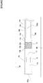
- FIG. 6 is an enlarged sectional view corresponding to FIG. 4 in a case that an indwelling device according to the second embodiment is disposed.
- FIG. 7 is an enlarged sectional view corresponding to FIG. 5 in a case that the indwelling device according to the second embodiment is disposed.
- the same members as in the first embodiment are given the same reference numerals as in the first embodiment, and the explanation of the same members is omitted.
- a medical appliance for inserting an indwelling device 10 according to the second embodiment into a patient's body is the same as the medical appliance 100.
- the indwelling device 10 is explained in such a way that the advancing direction of the medical appliance 100 i.e. a direction toward a patient's lesion is a distal end side and an opposite side thereto is a proximal end side.
- the indwelling device 10 includes the IC tag 9 that stores various information in the inside thereof.
- the indwelling device 10 is composed of a device body 13, and an engaging part 15 connected to the proximal end side of the device body 13.
- the device body 13 according to the second embodiment is also a hollow cylindrical member having a diameter of several millimeters.
- a resin material made of a biocompatible material e.g.
- various synthetic resin materials including a polyolefin resin such as a polyamide resin, a polyamide elastomer, a polyester, a polyurethane, a polyvinyl chloride resin, a polyethylene, a polypropylene and an ethylene-propylene copolymer, a fluororesin such as Teflon (registered trademark), an ethylene-vinyl acetate copolymer, and the like; as well as a metal material made of a biocompatible material can be used.
- a polyolefin resin such as a polyamide resin, a polyamide elastomer, a polyester, a polyurethane, a polyvinyl chloride resin, a polyethylene, a polypropylene and an ethylene-propylene copolymer, a fluororesin such as Teflon (registered trademark), an ethylene-vinyl acetate copolymer, and the like.
- the engaging part 15 is composed of a braid obtained by braiding a plurality of wires 15a wound in one direction and a plurality of wires 15b wound in a direction intersecting with the winding direction of the plurality of wires 15a.
- the engaging part 15 is wound around a proximal outer periphery of the device body 13 in a state that the braid is contracted.
- the plurality of the wires 15a and the plurality of the wires 15b are made of e.g. an NiTi shape-memory alloy.
- the device body 13 is composed of a distal end part 13a, a small-diameter part 13b having an outer diameter smaller than of the distal end part 13a, a tapered part 13c located on the proximal end side of the small-diameter part 13b and having a diameter gradually increasing toward the proximal direction, and a proximal end part 13d located on the proximal end side of the tapered part 13c and having an outer diameter larger than of the small-diameter part 13b.
- the engaging part 15 composed of the braid is stored on the small-diameter part 13b.
- the indwelling device 10 explained above is inserted into the catheter lumen 105 on the distal end of the catheter body 102, and the distal end of the pusher member 103 is abutted on the proximal end of the indwelling device 10. Then, the catheter body 102 in that state is inserted into the patient's body and advanced to the vicinity of the patient's lesion.
- FIG. 6 illustrates that state.
- the grip part body 106b is turned in the R1 direction with respect to the connector 104, the grip part 106 moves to the left side of the figure with respect to the connector 104, and at the same time, the pusher member 103 also moves to the left side of the figure, the indwelling device 10 is pushed out from the catheter body 102 as illustrated in FIG. 7 , and the engaging part 15 composed of the braid is expanded, so that the engaging part 15 abuts on and engages with the bodily wall 99 in a state that a region of the engaging part 15 excluding the end parts is expanded larger than the outer diameter of the device body 13.
- the indwelling device 10 includes the device body 13 and the engaging part 15 connected to the device body 13 and capable of abutting on the bodily wall 99. Since the engaging part 15 can abut on the bodily wall 99 in a state that the region of the engaging part 15 excluding the end parts is expanded larger than the outer diameter of the device body 13, the indwelling device 10 can be securely placed in the body without occluding the inside of the body and damaging the patient's bodily wall 99.
- the device body 13 includes a small-diameter part 13b having an outer diameter smaller than of other regions, and the engaging part 15 is stored on the small-diameter part 13b, so that the indwelling device 10 becomes easier to accommodate in the catheter lumen 105 of the catheter body 102, and deliverability of the indwelling device 10 can be improved.
- FIG. 8 is an overall view of an indwelling device according to the third embodiment.
- a medical appliance for inserting an indwelling device 20 according to the third embodiment into a patient's body is the same as the medical appliance 100. Also in the third embodiment, the indwelling device 20 is explained in such a way that an advancing direction of the medical appliance 100 i.e. a direction toward a patient's lesion is a distal end side and an opposite side thereto is a proximal end side.
- the indwelling device 20 includes the IC tag 9 that stores various information in the inside thereof.
- the indwelling device 20 is composed of a device body 23, and an engaging part 25 connected to the proximal end side of the device body 23.
- the device body 23 according to the third embodiment is composed of a distal end part 23a, a small-diameter part 23b having an outer diameter smaller than of the distal end part 23a, a tapered part 23c located on the proximal end side of the small-diameter part 23b and having a diameter gradually increasing toward the proximal direction, and a proximal end part 23d located on the proximal end side of the tapered part 23c and having an outer diameter larger than of the small-diameter part 23b.
- the device body 23 is also a hollow cylindrical member having a diameter of several millimeters.
- a resin material made of a biocompatible material e.g. various synthetic resin materials including a polyolefin resin such as a polyamide resin, a polyamide elastomer, a polyester, a polyurethane, a polyvinyl chloride resin, a polyethylene, a polypropylene and an ethylene-propylene copolymer, a fluororesin such as Teflon (registered trademark), an ethylene-vinyl acetate copolymer, and the like; as well as a metal material made of a biocompatible material can be used.
- a polyolefin resin such as a polyamide resin, a polyamide elastomer, a polyester, a polyurethane, a polyvinyl chloride resin, a polyethylene, a polypropylene and an ethylene-propylene copolymer, a fluororesin such as Tef
- the engaging part 25 according to the third embodiment is composed of a coil constructed by winding one NiTi shape-memory alloy wire in a hollow shape, and the engaging part 25 is wound around a proximal outer periphery of the device body 23 in a state that the coil is contracted.
- a distal end part 25a of the coil is fixed to the device body, a proximal end part 25b of the coil is a free end, and the engaging part 25 is stored on the small-diameter part 23b of the device body 23.
- the engaging part 25 according to the third embodiment is simply constructed by winding one NiTi shape-memory alloy wire in a hollow shape, the engaging part that exerts an effect described below in the third embodiment can be easily constructed.
- the indwelling device 20 explained above is inserted into the catheter lumen 105 on the distal end of the catheter body 102, and the distal end of the pusher member 103 is abutted on the proximal end of the indwelling device 20. Then, the catheter body 102 in that state is inserted into the patient's body and advanced to the vicinity of the patient's lesion.
- the whole indwelling device is not inserted into the catheter lumen 105 unlike the indwelling device 1 according to the first embodiment and the indwelling device 10 according to the second embodiment, and only the small-diameter part 23b, the tapered part 23c and the proximal end part 23d, as well as the engaging part 25 stored on the small-diameter part 23b are inserted into the catheter lumen 105.
- the grip part body 106b is turned in the R1 direction with respect to the connector 104, the grip part 106 moves to the left side of the figure with respect to the connector 104, and at the same time, the pusher member 103 also moves to the left side of the figure, the indwelling device 20 is pushed out from the catheter body 102, and the engaging part 25 composed of the coil is expanded, so that the engaging part 25 abuts on and engages with the bodily wall 99 in a state that a region of the engaging part 25 excluding the end parts is expanded larger than an outer diameter of the device body 23.
- the indwelling device 20 includes the device body 23 and the engaging part 25 connected to the device body 23 and capable of abutting on the bodily wall 99. Since the engaging part 25 can abut on the bodily wall 99 in a state that the region of the engaging part 25 excluding the end parts is expanded larger than the outer diameter of the device body 23, the indwelling device 20 can be securely placed in the body without occluding the inside of the body and damaging the patient's bodily wall 99.
- the device body 23 includes the small-diameter part 23b having the outer diameter smaller than of other regions, and the engaging part 25 is stored on the small-diameter part 23b, so that the indwelling device 20 becomes easier to accommodate in the catheter lumen 105 of the catheter body 102, and deliverability of the indwelling device 20 can be improved.
- FIG. 9 is an overall view of an indwelling device according to the fourth embodiment.
- a medical appliance for inserting an indwelling device 30 according to the fourth embodiment into a patient's body is the same as the medical appliance 100. Also in the fourth embodiment, the indwelling device 30 is explained in such a way that the advancing direction of the medical appliance 100 i.e. a direction toward a patient's lesion is a distal end side and an opposite side thereto is a proximal end side.
- the indwelling device 30 includes the IC tag 9 that stores various information in the inside thereof.
- the indwelling device 30 is composed of a device body 33, and an engaging part 35 connected to the proximal end side of the device body 33.
- the device body 33 according to the fourth embodiment is composed of a distal end part 33a, a small-diameter part 33b having an outer diameter smaller than of the distal end part 33a, a tapered part 33c located on the proximal end side of the small-diameter part 33b and having a diameter gradually increasing toward the proximal direction, and a proximal end part 33d located on the proximal end side of the tapered part 33c and having an outer diameter larger than of the small-diameter part 33b.
- the device body 33 is also a hollow cylindrical member having a diameter of several millimeters.
- a resin material made of a biocompatible material e.g.
- various synthetic resin materials including a polyolefin resin such as a polyamide resin, a polyamide elastomer, a polyester, a polyurethane, a polyvinyl chloride resin, a polyethylene, a polypropylene and an ethylene-propylene copolymer, a fluororesin such as Teflon (registered trademark), an ethylene-vinyl acetate copolymer, and the like; as well as a metal material made of a biocompatible material can be used.
- a polyolefin resin such as a polyamide resin, a polyamide elastomer, a polyester, a polyurethane, a polyvinyl chloride resin, a polyethylene, a polypropylene and an ethylene-propylene copolymer, a fluororesin such as Teflon (registered trademark), an ethylene-vinyl acetate copolymer, and the like.
- the engaging part 35 according to the fourth embodiment is composed of a coil constructed by winding one NiTi shape-memory alloy wire in a hollow shape, and the engaging part 35 is wound around a proximal outer periphery of the device body 33 in a state that the coil is contracted.
- a proximal end part 35a of the coil is fixed to the device body 33, a distal end part 35b of the coil is a free end, and the engaging part 35 is stored on the small-diameter part 33b of the device body 33.
- the engaging part 35 since the end part 35b on the side not connected to the device body 33 is located on the distal end side in an advancing direction of the indwelling device 30 while being placed in the body, the engaging part 35 can be swiftly abutted on the bodily wall 99, and consequently the indwelling device 30 can be swiftly placed in the patient's body.
- the engaging part 35 according to the fourth embodiment is simply constructed by winding one NiTi shape-memory alloy wire in a hollow shape, the engaging part that exerts an effect described below in the fourth embodiment can be easily constructed.
- the indwelling device 30 explained above is inserted into the catheter lumen 105 on the distal end of the catheter body 102, and the distal end of the pusher member 103 is abutted on the proximal end of the indwelling device 30. Then, the catheter body 102 in that state is inserted into the patient's body and advanced to the vicinity of the patient's lesion.
- the grip part body 106b is turned in the R1 direction with respect to the connector 104, the grip part 106 moves to the left side of the figure with respect to the connector 104, and at the same time, the pusher member 103 also moves to the left side of the figure, the indwelling device 30 is pushed out from the catheter body 102, and the engaging part 35 composed of the coil is expanded, so that the engaging part 35 abuts on and engages with the bodily wall 99 in a state that a region of the engaging part 35 excluding the end parts is expanded larger than an outer diameter of the device body 33.
- the indwelling device 30 includes the device body 33 and the engaging part 35 connected to the device body 33 and capable of abutting on the bodily wall 99. Since the engaging part 35 can abut on the bodily wall 99 in a state that the region of the engaging part 35 excluding the end parts is expanded larger than the outer diameter of the device body 33, the indwelling device 30 can be securely placed in the body without occluding the inside of the body and damaging the patient's bodily wall 99.
- the device body 33 includes the small-diameter part 33b having the outer diameter smaller than of other regions, and the engaging part 35 is stored on the small-diameter part 33b, so that the indwelling device 30 becomes easier to accommodate in the catheter lumen 105 of the catheter body 102, and deliverability of the indwelling device 30 can be improved.
- the end part 35b on the side not connected to the device body 33 is located closer to a distal end side in an advancing direction of the indwelling device 30 while being placed in the body than the end part 35a on the side connected to the device body 33, so that the engaging part 35 can be swiftly abutted on the bodily wall 99, and consequently the indwelling device 30 can be swiftly placed in the body.
- FIG. 10 is an overall view of an indwelling device according to the fourth embodiment.
- a medical appliance for inserting an indwelling device 40 according to the fifth embodiment into a patient's body is the same as the medical appliance 100. Also in the fifth embodiment, the indwelling device 40 is explained in such a way that the advancing direction of the medical appliance 100 i.e. a direction toward a patient's lesion is a distal end side and an opposite side thereto is a proximal end side.
- the indwelling device 40 includes the IC tag 9 that stores various information in the inside thereof.
- the indwelling device 40 is composed of a device body 43, and an engaging part 45 connected to the proximal end side of the device body 43.
- the device body 43 is composed of a distal end part 43a, a small-diameter part 43b having an outer diameter smaller than of the distal end part 43a, a tapered part 43c located on the proximal end side of the small-diameter part 43b and having a diameter gradually increasing toward the proximal direction, and a proximal end part 43d located on the proximal end side of the tapered part 43c and having an outer diameter larger than of the small-diameter part 43b.
- the device body 43 is also a hollow cylindrical member having a diameter of several millimeters.
- a resin material made of a biocompatible material e.g.
- various synthetic resin materials including a polyolefin resin such as a polyamide resin, a polyamide elastomer, a polyester, a polyurethane, a polyvinyl chloride resin, a polyethylene, a polypropylene and an ethylene-propylene copolymer, a fluororesin such as Teflon (registered trademark), an ethylene-vinyl acetate copolymer, and the like; as well as a metal material made of a biocompatible material can be used.
- a polyolefin resin such as a polyamide resin, a polyamide elastomer, a polyester, a polyurethane, a polyvinyl chloride resin, a polyethylene, a polypropylene and an ethylene-propylene copolymer, a fluororesin such as Teflon (registered trademark), an ethylene-vinyl acetate copolymer, and the like.
- the engaging part 45 according to the fifth embodiment is composed of a coil constructed by winding two NiTi shape-memory alloy wires in a hollow shape, and the engaging part 45 is wound around a proximal outer periphery of the device body 43 in a state that the coil is contracted.
- a proximal end part 45a and a proximal end part 45c of the coil are fixed to the device body 43, a distal end part 45b and a distal end part 45d of the coil are free ends, and the engaging part 45 is stored on the small-diameter part 43b of the device body 43.
- the engaging part 45 according to the fifth embodiment is simply constructed by winding two NiTi shape-memory alloy wires in a hollow shape, the engaging part that exerts an effect described below in the fifth embodiment can be easily constructed.
- the indwelling device 40 explained above is inserted into the catheter lumen 105 on the distal end of the catheter body 102, and the distal end of the pusher member 103 is abutted on the proximal end of the indwelling device 40. Then, the catheter body 102 in that state is inserted into the patient's body and advanced to the vicinity of the patient's lesion.
- the grip part body 106b is turned in the R1 direction with respect to the connector 104, the grip part 106 moves to the left side of the figure with respect to the connector 104, and at the same time, the pusher member 103 also moves to the left side of the figure, the indwelling device 40 is pushed out from the catheter body 102, and the engaging part 45 composed of the coil is expanded, so that the engaging part 45 abuts on and engages with the bodily wall 99 in a state that a region of the engaging part 45 excluding the end parts is expanded larger than an outer diameter of the device body 43.
- the indwelling device 40 includes the device body 43 and the engaging part 45 connected to the device body 43 and capable of abutting on the bodily wall 99. Since the engaging part 45 can abut on the bodily wall 99 in a state that the region of the engaging part 45 excluding the end parts is expanded larger than the outer diameter of the device body 43, the indwelling device 40 can be securely placed in the body without occluding the inside of the body and damaging the patient's bodily wall 99.
- the device body 43 includes the small-diameter part 43b having the outer diameter smaller than of other regions, and the engaging part 45 is stored on the small-diameter part 43b, so that the indwelling device 30 becomes easier to accommodate in the catheter lumen 105 of the catheter body 102, and deliverability of the indwelling device 40 can be improved.
- the end part 45b on the side not connected to the device body 43 is located closer to a distal end side in an advancing direction of the indwelling device 40 while being placed in the body than the end part 45a on the side connected to the device body 43, so that the engaging part 45 can be swiftly abutted on the bodily wall 99, and consequently the indwelling device 40 can be swiftly placed in the body.
- the indwelling device 40 of the fifth embodiment since the coil as the engaging part 45 is composed of two wires, the indwelling device 40 can be more firmly placed in the bodily wall 99.
- the engaging part 45 is formed as the coil composed of two NiTi shape-memory alloy wires
- the coil may be composed of two or more NiTi shape-memory alloy wires
- the coil as the engaging part 45 may be composed of a wire made of a biocompatible shape-memory alloy other than the NiTi shape-memory alloy.
- FIG. 11 is an overall view of an indwelling device according to the sixth embodiment.
- a medical appliance for inserting an indwelling device 50 according to the sixth embodiment into a patient's body is the same as the medical appliance 100.
- the indwelling device 50 is explained in such a way that the advancing direction of the medical appliance 100 i.e. a direction toward a patient's lesion is a distal end side and an opposite side thereto is a proximal end side.
- the indwelling device 50 includes the IC tag 9 that stores various information in the inside thereof, and the indwelling device 50 is composed of a device body 53 and an engaging part 55 connected to the distal end side of the device body 53. That means, unlike the device bodies according to the first to fifth embodiments, the device body 53 according to the sixth embodiment has a configuration in which the engaging part 55 is disposed on the distal end side of the device body 53.
- the device body 53 is composed of a small-diameter part 53b on the distal end side and a proximal end part 53a having an outer diameter larger than of the small-diameter part 53b.
- the device body 53 is also a hollow cylindrical member having a diameter of several millimeters.
- a resin material made of a biocompatible material e.g.
- various synthetic resin materials including a polyolefin resin such as a polyamide resin, a polyamide elastomer, a polyester, a polyurethane, a polyvinyl chloride resin, a polyethylene, a polypropylene and an ethylene-propylene copolymer, a fluororesin such as Teflon (registered trademark), an ethylene-vinyl acetate copolymer, and the like; as well as a metal material made of a biocompatible material can be used.
- a polyolefin resin such as a polyamide resin, a polyamide elastomer, a polyester, a polyurethane, a polyvinyl chloride resin, a polyethylene, a polypropylene and an ethylene-propylene copolymer, a fluororesin such as Teflon (registered trademark), an ethylene-vinyl acetate copolymer, and the like.
- the engaging part 55 according to the sixth embodiment is composed of a braid obtained by braiding a plurality of wires 55a wound in one direction and a plurality of wires 55b wound in a direction intersecting with the winding direction of the plurality of wires 55a.
- the engaging part 55 is stored on the small-diameter part 53b of the device body 53 in a state that the braid is contracted.
- the plurality of the wires 55a and the plurality of the wires 55b are made of e.g. an NiTi shape-memory alloy.
- the indwelling device 50 explained above is inserted into the catheter lumen 105 on the distal end of the catheter body 102, and the distal end of the pusher member 103 is abutted on the proximal end of the indwelling device 50. Then, the catheter body 102 in that state is inserted into the patient's body and advanced to the vicinity of the patient's lesion.
- the grip part body 106b is turned in the R1 direction with respect to the connector 104, the grip part 106 moves to the left side of the figure with respect to the connector 104, and at the same time, the pusher member 103 also moves to the left side of the figure, the indwelling device 50 is pushed out from the catheter body 102, and the engaging part 55 composed of the coil is expanded, so that the engaging part 55 abuts on and engages with the bodily wall 99 in a state that a region of the engaging part 55 excluding the end parts is expanded larger than an outer diameter of the device body 53.
- the indwelling device 50 includes the device body 53 and the engaging part 55 connected to the device body 53 and capable of abutting on the bodily wall 99. Since the engaging part 55 can abut on the bodily wall 99 in a state that the region of the engaging part 55 excluding the end parts is expanded larger than the outer diameter of the device body 53, the indwelling device 50 can be securely placed in the body without occluding the inside of the body and damaging the patient's bodily wall 99.
- the device body 53 includes the small-diameter part 53b having the outer diameter smaller than of other regions, and the engaging part 55 is wound around the small-diameter part 53b, so that the indwelling device 50 becomes easier to accommodate in the catheter lumen 105 of the catheter body 102, and deliverability of the indwelling device 50 can be improved.
- the engaging part 55 since the engaging part 55 is disposed on the distal end side of the device body 53, the engaging part 55 can be swiftly abutted on the bodily wall 99 before the whole indwelling device 50 is pushed out from the catheter body 102, and consequently the indwelling device 50 can be swiftly placed in the body.
- FIG. 12 is an overall view of an indwelling device according to the seventh embodiment.
- a medical appliance for inserting an indwelling device 60 according to the seventh embodiment into a patient's body is the same as the medical appliance 100. Also in the seventh embodiment, the indwelling device 60 is explained in such a way that the advancing direction of the medical appliance 100 i.e. a direction toward a patient's lesion is a distal end side and an opposite side thereto is a proximal end side.
- the indwelling device 60 includes the IC tag 9 that stores various information in the inside thereof.
- the indwelling device 60 is composed of a device body 63, and an engaging part 65 connected to the distal end side of the device body 63.
- the device body 63 is composed of a small-diameter part 63b on the distal end side and a proximal end part 63a having an outer diameter larger than of the small-diameter part 63b.
- the device body 63 is also a hollow cylindrical member having a diameter of several millimeters.
- a resin material made of a biocompatible material e.g.
- various synthetic resin materials including a polyolefin resin such as a polyamide resin, a polyamide elastomer, a polyester, a polyurethane, a polyvinyl chloride resin, a polyethylene, a polypropylene and an ethylene-propylene copolymer, a fluororesin such as Teflon (registered trademark), an ethylene-vinyl acetate copolymer, and the like; as well as a metal material made of a biocompatible material can be used.
- a polyolefin resin such as a polyamide resin, a polyamide elastomer, a polyester, a polyurethane, a polyvinyl chloride resin, a polyethylene, a polypropylene and an ethylene-propylene copolymer, a fluororesin such as Teflon (registered trademark), an ethylene-vinyl acetate copolymer, and the like.
- the engaging part 65 according to the seventh embodiment is composed of a coil constructed by winding one NiTi shape-memory alloy wire in a hollow shape, and the engaging part 65 is wound around an outer periphery of the small-diameter part 63b of the device body 63 in a state that the coil is contracted.
- a proximal end part 65a of the coil is fixed to the device body, and a distal end part 65b of the coil is a free end.
- the engaging part 65 since the end part 65b on the side not connected to the device body 63 is located on the distal end side in an advancing direction of the indwelling device 60 while being placed in the body, the engaging part 65 can be swiftly abutted on the bodily wall 99, and consequently the indwelling device 30 can be swiftly placed in the patient's body.
- the engaging part 65 according to the seventh embodiment is simply constructed by winding one NiTi shape-memory alloy wire in a hollow shape, the engaging part that exerts an effect described below in the seventh embodiment can be easily constructed.
- the indwelling device 60 explained above is inserted into the catheter lumen 105 on the distal end of the catheter body 102, and the distal end of the pusher member 103 is abutted on the proximal end of the indwelling device 60. Then, the catheter body 102 in that state is inserted into the patient's body and advanced to the vicinity of the patient's lesion.
- the grip part body 106b is turned in the R1 direction with respect to the connector 104, the grip part 106 moves to the left side of the figure with respect to the connector 104, and at the same time, the pusher member 103 also moves to the left side of the figure, the indwelling device 60 is pushed out from the catheter body 102, and the engaging part 65 composed of the coil is expanded, so that the engaging part 65 abuts on and engages with the bodily wall 99 in a state that a region of the engaging part 36 excluding the end parts is expanded larger than an outer diameter of the device body 63.
- the indwelling device 60 includes the device body 63 and the engaging part 65 connected to the device body 63 and capable of abutting on the bodily wall 99. Since the engaging part 65 can abut on the bodily wall 99 in a state that the region of the engaging part 65 excluding the end parts is expanded larger than the outer diameter of the device body 63, the indwelling device 60 can be securely placed in the body without occluding the inside of the body and damaging the patient's bodily wall 99.
- the device body 63 includes the small-diameter part 63b having the outer diameter smaller than of other regions, and the engaging part 65 is wound around the small-diameter part 63b, so that the indwelling device 60 becomes easier to accommodate in the catheter lumen 105 of the catheter body 102, and deliverability of the indwelling device 60 can be improved.
- the engaging part 65 is disposed on the distal end side of the device body 63, and in the coil of the engaging part 65, the end part 65b on the side not connected to the device body 63 is located closer to a distal end side in an advancing direction of the indwelling device 60 while being placed in the body than the end part 65a on the side connected to the device body 63, so that the engaging part 65 can be more swiftly abutted on the bodily wall 99, and consequently the indwelling device 60 can be more swiftly placed in the body.
- the engaging part 5 according to the first embodiment and the engaging part 45 according to the fifth embodiment may be connected to the small-diameter part 63b of the device body 63 according to the seventh embodiment.
- the engaging part 5 and the engaging part 45 can be swiftly abutted on the bodily wall 99, and consequently the indwelling device can be swiftly placed in the body.
- the engaging part 15 according to the second embodiment, the engaging part 35 according to the fourth embodiment, and the engaging part 45 according to the fifth embodiment can also be connected to the proximal end side of the device body 3 according to the first embodiment.
Landscapes
- Health & Medical Sciences (AREA)
- Life Sciences & Earth Sciences (AREA)
- Surgery (AREA)
- Engineering & Computer Science (AREA)
- Biomedical Technology (AREA)
- Animal Behavior & Ethology (AREA)
- Veterinary Medicine (AREA)
- Oral & Maxillofacial Surgery (AREA)
- Public Health (AREA)
- Heart & Thoracic Surgery (AREA)
- General Health & Medical Sciences (AREA)
- Molecular Biology (AREA)
- Medical Informatics (AREA)
- Pathology (AREA)
- Nuclear Medicine, Radiotherapy & Molecular Imaging (AREA)
- Physics & Mathematics (AREA)
- Electromagnetism (AREA)
- Cardiology (AREA)
- Transplantation (AREA)
- Vascular Medicine (AREA)
- Media Introduction/Drainage Providing Device (AREA)
- Materials For Medical Uses (AREA)
- Surgical Instruments (AREA)
Abstract
Description
- The present invention relates to an indwelling device that is placed in a patient's body lumen, such as a bronchus of a lung and a blood vessel in a patient.
- In conventional surgery or the like, a technique, so-called RFID (radio frequency identifier) has been used, in which a wireless marker is embedded in or near a patient's lesion, and a position of the patient's lesion is specified by wireless communication between the wireless marker and a device outside of the patient's body.
- For example, Patent Document 1 describes that a wireless marker is embedded in a lesion in a bronchus of a patient's lung, and, during surgery or the like, a position of a lesion is informed to an operator in real time by wireless communication between a position-specifying system outside of the patient's body and the wireless marker (see
FIG. 8 and the like). - In addition, the wireless marker used for this position-specifying system includes a leg (hereinafter referred to as "engagement part") as a mechanism for the wireless marker to be fixed inside the patient's body (see FIG. 13 and the like).
- Patent Literature 1:
Japanese Unexamined Patent Application Publication No. 2013-543401 - However, the conventional wireless marker has had a problem that a hook-shaped proximal end part of an engaging part is likely to damage a patient's bodily wall.
- In addition, the conventional wireless marker has had a problem that, due to a relationship between a shape of a wireless marker body and a shape of the engaging part, the wireless marker is likely to occlude a patient's body lumen when disposing the wireless marker in the patient's body lumen.
- Also, the conventional wireless marker has had a problem that the wireless marker is difficult to insert into a catheter lumen and also difficult to carry thereafter because the engaging part is disposed so as to project from a proximal end of the wireless marker toward the proximal end side.
- Furthermore, the conventional wireless marker has had a problem that, since the engaging part is disposed on the proximal end part of the wireless marker, it is not until the whole wireless marker leaves from a distal end of a catheter for conveying the wireless marker that the wireless marker engages with the patient's body lumen, and therefore the wireless marker cannot be swiftly disposed in the patient's body lumen.
- The present invention has been made in response to the aforementioned problems of the prior art, and objects of the present invention is to provide an indwelling device that does not occlude an inside of a body and does not damage a patient's bodily wall, and to provide an indwelling device that can be easily accommodated in a lumen such as a catheter and improves deliverability of the indwelling device, and further to provide an indwelling device that has an engaging part capable of swiftly abutting on the bodily wall and consequently can be swiftly placed in the body.
- In order to solve the aforementioned problems, the first aspect of the present invention is characterized in that, in an indwelling device including a device body and an engaging part connected to the device body and capable of abutting on a bodily wall, the engaging part can abut on the bodily wall in a state that a region of the engaging part, excluding end parts, is expanded larger than an outer diameter of the device body.
- In addition, the second aspect of the present invention is characterized in that, in the indwelling device according to the first aspect, the device body has a small-diameter part having an outer diameter smaller than of other regions, and the engaging part can be stored on the small-diameter part.
- In addition, the third aspect of the present invention is characterized in that, in the indwelling device according to the first or second aspect, the engaging part is constructed by spirally winding one or more wires.
- Furthermore, the fourth aspect of the present invention is characterized in that, in the indwelling device according to the third aspect, an end part of the wire on a side not connected to the device body is located on a distal end side in an advancing direction of the indwelling device while being placed in a body.
- According to the first aspect of the present invention, in the indwelling device including the device body and the engaging part connected to the device body and capable of abutting on the bodily wall, the engaging part can abut on the bodily wall in a state that the region of the engaging part excluding the end parts is expanded larger than the outer diameter of the device body, and therefore the indwelling device can be securely placed in the body without occluding the inside of the body and damaging the patient's bodily wall.
- In addition, according to the second aspect of the present invention, in the indwelling device according to the first aspect, the device body has the small-diameter part having the outer diameter smaller than of other regions, and the engaging part can be stored on the small-diameter part, so that not only is the effect of the indwelling device according to the first aspect obtained but the indwelling device also becomes easier to accommodate in a lumen such as a catheter, and deliverability of the indwelling device can be improved.
- In addition, according to the third aspect of the present invention, in the indwelling device according to the first or second aspect, the engaging part is constructed by spirally winding one or more wires, and therefore not only is the effect of the indwelling device according to the first or second aspect obtained but an engaging part that exhibits such an effect can also be easily constructed.
- Furthermore, according to the fourth aspect of the present invention, in the indwelling device according to the third aspect, the end part of the wire on the side not connected to the device body is located on the distal end side in the advancing direction of the indwelling device while being placed in a body, and therefore not only is the effect of the indwelling device according to the third aspect obtained but the engaging part can also be swiftly abutted on the bodily wall, and consequently the indwelling device can be swiftly placed in the body.
-
-
FIG. 1 is a schematic overall view of a medical appliance for placing an indwelling device according to the first embodiment of the present invention in a body. -
FIG. 2 is a longitudinal sectional view ofFIG. 1 . -
FIG. 3 is a longitudinal sectional view of the medical appliance, illustrating a state that the indwelling device according to the first embodiment is pushed out from the medical appliance. -
FIG. 4 is an enlarged sectional view of a part A inFIG. 2 . -
FIG. 5 is an enlarged sectional view of a part B inFIG. 3 . -
FIG. 6 is an enlarged sectional view corresponding toFIG. 4 in a case that an indwelling device according to the second embodiment is disposed. -
FIG. 7 is an enlarged sectional view corresponding toFIG. 5 in a case that an indwelling device according to the second embodiment is disposed. -
FIG. 8 is an overall view of an indwelling device according to the third embodiment. -
FIG. 9 is an overall view of an indwelling device according to the fourth embodiment. -
FIG. 10 is an overall view of an indwelling device according to the fifth embodiment. -
FIG. 11 is an overall view of an indwelling device according to the sixth embodiment. -
FIG. 12 is an overall view of an indwelling device according to the seventh embodiment. - Hereinafter, embodiments of the present invention will be explained with reference to the drawings.
- First, the first embodiment of the present invention will be explained.
-
FIG. 1 is a schematic overall view of a medical appliance for placing an indwelling device according to the first embodiment of the present invention in a body.FIG. 2 is a longitudinal sectional view ofFIG. 1 .FIG. 3 is a longitudinal sectional view of the medical appliance, illustrating a state that the indwelling device according to the first embodiment is pushed out from the medical appliance.FIG. 4 is an enlarged sectional view of a part A inFIG. 2 .FIG. 5 is an enlarged sectional view of a part B inFIG. 3 . - As illustrated in
FIG. 1 to FIG. 3 , amedical appliance 100 for placing an indwelling device 1 (seeFIG. 2 to FIG. 5 ) according to the first embodiment described below in a patient's body is composed of acatheter body 102, aconnector 104 connected to a proximal end of thecatheter body 102, apusher member 103 slidably inserted into acatheter lumen 105 of thecatheter body 102 as well as a distal end-side lumen 101a and anintermediate lumen 101b of theconnector 104, and agrip part 106 abutting on a proximal end of thepusher member 103. - The
catheter body 102 is a hollow cylindrical flexible long member and has thecatheter lumen 105 inside thereof and an opening 102a on the distal end thereof. - A material for the
catheter body 102 is a resin material made of a biocompatible material. Various synthetic resin materials, for example, a polyolefin resin such as a polyamide resin, a polyamide elastomer, a polyester, a polyurethane, a polyvinyl chloride resin, a polyethylene, a polypropylene, and an ethylene-propylene copolymer, a fluororesin such as Teflon (registered trademark), an ethylene-vinyl acetate copolymer can be used, and in the first embodiment, a polyamide elastomer is used. - The
pusher member 103 is composed of a solid cylindrical flexiblelong member 103a and anabutting part 103b connected to the proximal end of thelong member 103a. Thepusher member 103 is slidably inserted into thecatheter lumen 105 of thecatheter body 102, a distal end of thepusher member 103 is located in the vicinity of a distal end of thecatheter body 102, and the proximal end of thepusher member 103 is located inside of theconnector 104. - Incidentally, a material for the flexible
long member 103a of thepusher member 103 is a metal material made of a biocompatible material, and for example, various metal materials such as a stainless steel, an NiTi shape - memory alloy, and a cobalt-chromium alloy can be used, and in the first embodiment, a stainless steel is used. - In addition, a material for the
abutting part 103b of thepusher member 103 is not particularly limited, and an ordinary resin material such as polyacetal and polycarbonate can be used. - In the
grip part 106, ascrew part 106a located on the distal end and agrip part body 106b connected to a proximal end of thescrew part 106a and having an outer diameter larger than of thescrew part 106a are integrally formed. - A material for the
grip part 106 is not particularly limited as long as the material has a higher rigidity than of thecatheter body 102. For example, a polyethylene, a polypropylene, a polycarbonate, a polyacetal, a polyvinyl chloride (PVC), a polybutadiene (PBD), an ABS resin, or the like can be used, and in the first embodiment, a polyvinyl chloride (PVC) is used. - The
connector 104 is a hollow member having a tapered distal end side and a hollow cylindrical proximal end side, and the distal end is connected to the proximal end of thecatheter body 102. Theconnector 104 has the distal end-side lumen 101a that communicates with thecatheter lumen 105 of thecatheter body 102 through acircular opening 101d located on the distal end of theconnector 104, theintermediate lumen 101b located on a middle part of theconnector 104, and a proximal end-side lumen 101c located on the proximal end side of theconnector 104. - In addition, the
connector 104 has anintermediate wall 104a between the distal end-side lumen 101a and theintermediate lumen 101b, and acircular opening 101e is formed in the center of theintermediate wall 104a. In addition, aspiral screw groove 104b is formed on an inner surface of theconnector 104, where the proximal end-side lumen 101c of theconnector 104 is formed. - The
screw part 106a of thegrip part 106 is screwed into thescrew groove 104b of theconnector 104. Thus, when thegrip part body 106b is turned in a R1 direction (clockwise direction toward the distal direction) with respect to theconnector 104, thegrip part 106 moves to the left side of the figure with respect to theconnector 104. - A proximal end of the flexible
long member 103a of thepusher member 103 is inserted through the opening 101d and the opening 101e of theconnector 104 to theintermediate lumen 101b of theconnector 104, and theabutting part 103b located on the proximal end of thepusher member 103 is disposed inside of theintermediate lumen 101b of theconnector 104. - Herein, in the
intermediate lumen 101b of theconnector 104, acompression spring 109 is disposed between theintermediate wall 104a and theabutting part 103b of thepusher member 103, and thecompression spring 109 always acts so as to energize theabutting part 103b toward the right side of the figure. - Thus, when the
grip part body 106b is turned in the R1 direction with respect to theconnector 104, thegrip part 106 moves to the left side of the figure with respect to theconnector 104 against an energizing force of thecompression spring 109 for energizing theabutting part 103b toward the right side of the figure, and at the same time, thepusher member 103 also moves to the left side of the figure. - On the other hand, when the
grip part body 106b is turned in an inverse R1 direction with respect to theconnector 104, theabutting part 103b is energized toward the right side of the figure by thecompression spring 109, so that thegrip part 106 moves to the right side of the figure with respect to theconnector 104, and at the same time, thepusher member 103 also moves to the right side of the figure. - Also, a material for the
connector 104 is not particularly limited as long as the material has a higher rigidity than of thecatheter body 102. For example, a polyethylene, a polypropylene, a polycarbonate, a polyacetal, a polyvinyl chloride (PVC), a polybutadiene (PBD), an ABS resin, or the like can be used, and in the first embodiment, a polyvinyl chloride (PVC) is used. - Herein, the indwelling device 1 according to the first embodiment will be explained. The indwelling device 1 is explained in such a way that the advancing direction of the
medical appliance 100 i.e. a direction toward a patient's lesion is a distal end side and an opposite side thereto is a proximal end side. - As illustrated in
FIG. 4 , the indwelling device 1 includes anIC tag 9 that stores various information in an inside thereof. The indwelling device 1 is composed of thedevice body 3, and theengaging part 5 connected to the proximal end side of thedevice body 3. - The
device body 3 according to the first embodiment is a hollow cylindrical member having a diameter of several millimeters. As a material for thedevice body 3, a resin material made of a biocompatible material, e.g. various synthetic resin materials including a polyolefin resin such as a polyamide resin, a polyamide elastomer, a polyester, a polyurethane, a polyvinyl chloride resin, a polyethylene, a polypropylene and an ethylene-propylene copolymer, a fluororesin such as Teflon (registered trademark), an ethylene-vinyl acetate copolymer, and the like; as well as a metal material made of a biocompatible material can be used. - The
engaging part 5 according to the first embodiment is composed of a coil constructed by winding one NiTi shape-memory alloy wire in a hollow shape, and theengaging part 5 is wound around a proximal outer periphery of thedevice body 3 in a state that the coil is contracted. Incidentally, in theengaging part 5 according to the first embodiment, adistal end part 5a of the coil is fixed to the device body, and aproximal end part 5b of the coil is a free end. - Incidentally, since the
engaging part 5 according to the first embodiment is simply constructed by winding one NiTi shape-memory alloy wire in a hollow shape, the engaging part that exerts an effect described below in the first embodiment can be easily constructed. - The indwelling device 1 explained above is inserted into the
catheter lumen 105 on the distal end of thecatheter body 102, and the distal end of thepusher member 103 is abutted on the proximal end of the indwelling device 1. Then, thecatheter body 102 in that state is inserted into the patient's body and advanced to the vicinity of the patient's lesion.FIG. 2 andFIG. 4 illustrate that state. - In addition to
FIG. 2 andFIG. 3 ,FIG. 4 andFIG. 5 illustrate thebodily wall 99 in the patient's lesion for the purpose of explaining an engaging state of the indwelling device. - Then, when the
grip part body 106b is turned in the R1 direction with respect to theconnector 104, thegrip part 106 moves to the left side of the figure with respect to theconnector 104, and at the same time, thepusher member 103 also moves to the left side of the figure, the indwelling device 1 is pushed out from thecatheter body 102 as illustrated inFIG. 3 andFIG. 5 , and theengaging part 5 composed of the coil is expanded, so that theengaging part 5 abuts on and engages with thebodily wall 99 in a state that a region of theengaging part 5 excluding the end parts is expanded larger than an outer diameter of thedevice body 3. - The indwelling device 1 according to the first embodiment includes the
device body 3 and theengaging part 5 connected to thedevice body 3 and capable of abutting on thebodily wall 99. Since theengaging part 5 can abut on thebodily wall 99 in a state that the region of theengaging part 15 excluding theend parts device body 3, the indwelling device 1 can be securely placed in the body without occluding the inside of the body and damaging the patient's bodily wall. - Next, the second embodiment of the present invention will be explained.
FIG. 6 is an enlarged sectional view corresponding toFIG. 4 in a case that an indwelling device according to the second embodiment is disposed.FIG. 7 is an enlarged sectional view corresponding toFIG. 5 in a case that the indwelling device according to the second embodiment is disposed. - In the second embodiment, the same members as in the first embodiment are given the same reference numerals as in the first embodiment, and the explanation of the same members is omitted. In addition, a medical appliance for inserting an
indwelling device 10 according to the second embodiment into a patient's body is the same as themedical appliance 100. - Also in the second embodiment, the indwelling
device 10 is explained in such a way that the advancing direction of themedical appliance 100 i.e. a direction toward a patient's lesion is a distal end side and an opposite side thereto is a proximal end side. - As illustrated in
FIG. 6 , the indwellingdevice 10 includes theIC tag 9 that stores various information in the inside thereof. Theindwelling device 10 is composed of adevice body 13, and anengaging part 15 connected to the proximal end side of thedevice body 13. - Like the
device body 3 according to the first embodiment, thedevice body 13 according to the second embodiment is also a hollow cylindrical member having a diameter of several millimeters. As a material for thedevice body 13, a resin material made of a biocompatible material, e.g. various synthetic resin materials including a polyolefin resin such as a polyamide resin, a polyamide elastomer, a polyester, a polyurethane, a polyvinyl chloride resin, a polyethylene, a polypropylene and an ethylene-propylene copolymer, a fluororesin such as Teflon (registered trademark), an ethylene-vinyl acetate copolymer, and the like; as well as a metal material made of a biocompatible material can be used. - The engaging
part 15 according to the second embodiment is composed of a braid obtained by braiding a plurality ofwires 15a wound in one direction and a plurality ofwires 15b wound in a direction intersecting with the winding direction of the plurality ofwires 15a. The engagingpart 15 is wound around a proximal outer periphery of thedevice body 13 in a state that the braid is contracted. The plurality of thewires 15a and the plurality of thewires 15b are made of e.g. an NiTi shape-memory alloy. - Incidentally, the
device body 13 according to the second embodiment is composed of adistal end part 13a, a small-diameter part 13b having an outer diameter smaller than of thedistal end part 13a, atapered part 13c located on the proximal end side of the small-diameter part 13b and having a diameter gradually increasing toward the proximal direction, and aproximal end part 13d located on the proximal end side of thetapered part 13c and having an outer diameter larger than of the small-diameter part 13b. In addition, the engagingpart 15 composed of the braid is stored on the small-diameter part 13b. - The
indwelling device 10 explained above is inserted into thecatheter lumen 105 on the distal end of thecatheter body 102, and the distal end of thepusher member 103 is abutted on the proximal end of theindwelling device 10. Then, thecatheter body 102 in that state is inserted into the patient's body and advanced to the vicinity of the patient's lesion.FIG. 6 illustrates that state. - Then, when the
grip part body 106b is turned in the R1 direction with respect to theconnector 104, thegrip part 106 moves to the left side of the figure with respect to theconnector 104, and at the same time, thepusher member 103 also moves to the left side of the figure, the indwellingdevice 10 is pushed out from thecatheter body 102 as illustrated inFIG. 7 , and theengaging part 15 composed of the braid is expanded, so that the engagingpart 15 abuts on and engages with thebodily wall 99 in a state that a region of theengaging part 15 excluding the end parts is expanded larger than the outer diameter of thedevice body 13. - The
indwelling device 10 according to the second embodiment includes thedevice body 13 and theengaging part 15 connected to thedevice body 13 and capable of abutting on thebodily wall 99. Since the engagingpart 15 can abut on thebodily wall 99 in a state that the region of theengaging part 15 excluding the end parts is expanded larger than the outer diameter of thedevice body 13, the indwellingdevice 10 can be securely placed in the body without occluding the inside of the body and damaging the patient'sbodily wall 99. - Additionally, according to the
indwelling device 10 of the second embodiment, thedevice body 13 includes a small-diameter part 13b having an outer diameter smaller than of other regions, and theengaging part 15 is stored on the small-diameter part 13b, so that theindwelling device 10 becomes easier to accommodate in thecatheter lumen 105 of thecatheter body 102, and deliverability of theindwelling device 10 can be improved. - Next, the third embodiment of the present invention will be explained.
FIG. 8 is an overall view of an indwelling device according to the third embodiment. - Incidentally, a medical appliance for inserting an
indwelling device 20 according to the third embodiment into a patient's body is the same as themedical appliance 100. Also in the third embodiment, the indwellingdevice 20 is explained in such a way that an advancing direction of themedical appliance 100 i.e. a direction toward a patient's lesion is a distal end side and an opposite side thereto is a proximal end side. - As illustrated in
FIG. 8 , the indwellingdevice 20 includes theIC tag 9 that stores various information in the inside thereof. Theindwelling device 20 is composed of adevice body 23, and anengaging part 25 connected to the proximal end side of thedevice body 23. - The
device body 23 according to the third embodiment is composed of adistal end part 23a, a small-diameter part 23b having an outer diameter smaller than of thedistal end part 23a, atapered part 23c located on the proximal end side of the small-diameter part 23b and having a diameter gradually increasing toward the proximal direction, and aproximal end part 23d located on the proximal end side of thetapered part 23c and having an outer diameter larger than of the small-diameter part 23b. - Incidentally, like the
device body 3 according to the first embodiment, thedevice body 23 is also a hollow cylindrical member having a diameter of several millimeters. As a material for thedevice body 23, a resin material made of a biocompatible material, e.g. various synthetic resin materials including a polyolefin resin such as a polyamide resin, a polyamide elastomer, a polyester, a polyurethane, a polyvinyl chloride resin, a polyethylene, a polypropylene and an ethylene-propylene copolymer, a fluororesin such as Teflon (registered trademark), an ethylene-vinyl acetate copolymer, and the like; as well as a metal material made of a biocompatible material can be used. - The engaging
part 25 according to the third embodiment is composed of a coil constructed by winding one NiTi shape-memory alloy wire in a hollow shape, and theengaging part 25 is wound around a proximal outer periphery of thedevice body 23 in a state that the coil is contracted. Incidentally, in the engagingpart 25 according to the third embodiment, adistal end part 25a of the coil is fixed to the device body, aproximal end part 25b of the coil is a free end, and theengaging part 25 is stored on the small-diameter part 23b of thedevice body 23. - Incidentally, since the engaging
part 25 according to the third embodiment is simply constructed by winding one NiTi shape-memory alloy wire in a hollow shape, the engaging part that exerts an effect described below in the third embodiment can be easily constructed. - The
indwelling device 20 explained above is inserted into thecatheter lumen 105 on the distal end of thecatheter body 102, and the distal end of thepusher member 103 is abutted on the proximal end of theindwelling device 20. Then, thecatheter body 102 in that state is inserted into the patient's body and advanced to the vicinity of the patient's lesion. - Incidentally, as the
indwelling device 20 according to the third embodiment, the whole indwelling device is not inserted into thecatheter lumen 105 unlike the indwelling device 1 according to the first embodiment and theindwelling device 10 according to the second embodiment, and only the small-diameter part 23b, thetapered part 23c and theproximal end part 23d, as well as the engagingpart 25 stored on the small-diameter part 23b are inserted into thecatheter lumen 105. - Thus, a pushed length of the
indwelling device 20 pushed out from thecatheter body 102 is shortened, the engagingpart 25 can be swiftly abutted on thebodily wall 99, and consequently theindwelling device 20 can be swiftly placed in the patient's body. - Then, when the
grip part body 106b is turned in the R1 direction with respect to theconnector 104, thegrip part 106 moves to the left side of the figure with respect to theconnector 104, and at the same time, thepusher member 103 also moves to the left side of the figure, the indwellingdevice 20 is pushed out from thecatheter body 102, and theengaging part 25 composed of the coil is expanded, so that the engagingpart 25 abuts on and engages with thebodily wall 99 in a state that a region of theengaging part 25 excluding the end parts is expanded larger than an outer diameter of thedevice body 23. - The
indwelling device 20 according to the third embodiment includes thedevice body 23 and theengaging part 25 connected to thedevice body 23 and capable of abutting on thebodily wall 99. Since the engagingpart 25 can abut on thebodily wall 99 in a state that the region of theengaging part 25 excluding the end parts is expanded larger than the outer diameter of thedevice body 23, the indwellingdevice 20 can be securely placed in the body without occluding the inside of the body and damaging the patient'sbodily wall 99. - Additionally, according to the
indwelling device 20 of the third embodiment, thedevice body 23 includes the small-diameter part 23b having the outer diameter smaller than of other regions, and theengaging part 25 is stored on the small-diameter part 23b, so that theindwelling device 20 becomes easier to accommodate in thecatheter lumen 105 of thecatheter body 102, and deliverability of theindwelling device 20 can be improved. - Next, the fourth embodiment of the present invention will be explained.
FIG. 9 is an overall view of an indwelling device according to the fourth embodiment. - Incidentally, a medical appliance for inserting an
indwelling device 30 according to the fourth embodiment into a patient's body is the same as themedical appliance 100. Also in the fourth embodiment, the indwellingdevice 30 is explained in such a way that the advancing direction of themedical appliance 100 i.e. a direction toward a patient's lesion is a distal end side and an opposite side thereto is a proximal end side. - As illustrated in
FIG. 9 , the indwellingdevice 30 includes theIC tag 9 that stores various information in the inside thereof. Theindwelling device 30 is composed of adevice body 33, and anengaging part 35 connected to the proximal end side of thedevice body 33. - The
device body 33 according to the fourth embodiment is composed of adistal end part 33a, a small-diameter part 33b having an outer diameter smaller than of thedistal end part 33a, atapered part 33c located on the proximal end side of the small-diameter part 33b and having a diameter gradually increasing toward the proximal direction, and aproximal end part 33d located on the proximal end side of thetapered part 33c and having an outer diameter larger than of the small-diameter part 33b. - Incidentally, like the
device body 3 according to the first embodiment, thedevice body 33 is also a hollow cylindrical member having a diameter of several millimeters. As a material for thedevice body 33, a resin material made of a biocompatible material, e.g. various synthetic resin materials including a polyolefin resin such as a polyamide resin, a polyamide elastomer, a polyester, a polyurethane, a polyvinyl chloride resin, a polyethylene, a polypropylene and an ethylene-propylene copolymer, a fluororesin such as Teflon (registered trademark), an ethylene-vinyl acetate copolymer, and the like; as well as a metal material made of a biocompatible material can be used. - The engaging
part 35 according to the fourth embodiment is composed of a coil constructed by winding one NiTi shape-memory alloy wire in a hollow shape, and theengaging part 35 is wound around a proximal outer periphery of thedevice body 33 in a state that the coil is contracted. Incidentally, unlike the engagingpart 25 according to the third embodiment, in the engagingpart 35 according to the fourth embodiment, aproximal end part 35a of the coil is fixed to thedevice body 33, adistal end part 35b of the coil is a free end, and theengaging part 35 is stored on the small-diameter part 33b of thedevice body 33. - That means, in the engaging
part 35 according to the fourth embodiment, since theend part 35b on the side not connected to thedevice body 33 is located on the distal end side in an advancing direction of theindwelling device 30 while being placed in the body, the engagingpart 35 can be swiftly abutted on thebodily wall 99, and consequently theindwelling device 30 can be swiftly placed in the patient's body. - In addition, since the engaging
part 35 according to the fourth embodiment is simply constructed by winding one NiTi shape-memory alloy wire in a hollow shape, the engaging part that exerts an effect described below in the fourth embodiment can be easily constructed. - The
indwelling device 30 explained above is inserted into thecatheter lumen 105 on the distal end of thecatheter body 102, and the distal end of thepusher member 103 is abutted on the proximal end of theindwelling device 30. Then, thecatheter body 102 in that state is inserted into the patient's body and advanced to the vicinity of the patient's lesion. - Then, when the
grip part body 106b is turned in the R1 direction with respect to theconnector 104, thegrip part 106 moves to the left side of the figure with respect to theconnector 104, and at the same time, thepusher member 103 also moves to the left side of the figure, the indwellingdevice 30 is pushed out from thecatheter body 102, and theengaging part 35 composed of the coil is expanded, so that the engagingpart 35 abuts on and engages with thebodily wall 99 in a state that a region of theengaging part 35 excluding the end parts is expanded larger than an outer diameter of thedevice body 33. - The
indwelling device 30 according to the fourth embodiment includes thedevice body 33 and theengaging part 35 connected to thedevice body 33 and capable of abutting on thebodily wall 99. Since the engagingpart 35 can abut on thebodily wall 99 in a state that the region of theengaging part 35 excluding the end parts is expanded larger than the outer diameter of thedevice body 33, the indwellingdevice 30 can be securely placed in the body without occluding the inside of the body and damaging the patient'sbodily wall 99. - Additionally, according to the
indwelling device 30 of the fourth embodiment, thedevice body 33 includes the small-diameter part 33b having the outer diameter smaller than of other regions, and theengaging part 35 is stored on the small-diameter part 33b, so that theindwelling device 30 becomes easier to accommodate in thecatheter lumen 105 of thecatheter body 102, and deliverability of theindwelling device 30 can be improved. - Furthermore, according to the
indwelling device 30 of the fourth embodiment, in the coil of theengaging part 35, theend part 35b on the side not connected to thedevice body 33 is located closer to a distal end side in an advancing direction of theindwelling device 30 while being placed in the body than theend part 35a on the side connected to thedevice body 33, so that the engagingpart 35 can be swiftly abutted on thebodily wall 99, and consequently theindwelling device 30 can be swiftly placed in the body. - Next, the fourth embodiment of the present invention will be explained.
FIG. 10 is an overall view of an indwelling device according to the fourth embodiment. - Incidentally, a medical appliance for inserting an
indwelling device 40 according to the fifth embodiment into a patient's body is the same as themedical appliance 100. Also in the fifth embodiment, the indwellingdevice 40 is explained in such a way that the advancing direction of themedical appliance 100 i.e. a direction toward a patient's lesion is a distal end side and an opposite side thereto is a proximal end side. - As illustrated in
FIG. 10 , the indwellingdevice 40 includes theIC tag 9 that stores various information in the inside thereof. Theindwelling device 40 is composed of adevice body 43, and anengaging part 45 connected to the proximal end side of thedevice body 43. - The
device body 43 according to the fifth embodiment is composed of adistal end part 43a, a small-diameter part 43b having an outer diameter smaller than of thedistal end part 43a, atapered part 43c located on the proximal end side of the small-diameter part 43b and having a diameter gradually increasing toward the proximal direction, and aproximal end part 43d located on the proximal end side of thetapered part 43c and having an outer diameter larger than of the small-diameter part 43b. - Incidentally, like the
device body 3 according to the first embodiment, thedevice body 43 is also a hollow cylindrical member having a diameter of several millimeters. As a material for thedevice body 43, a resin material made of a biocompatible material, e.g. various synthetic resin materials including a polyolefin resin such as a polyamide resin, a polyamide elastomer, a polyester, a polyurethane, a polyvinyl chloride resin, a polyethylene, a polypropylene and an ethylene-propylene copolymer, a fluororesin such as Teflon (registered trademark), an ethylene-vinyl acetate copolymer, and the like; as well as a metal material made of a biocompatible material can be used. - Unlike the engaging
part 35 according to the fourth embodiment, the engagingpart 45 according to the fifth embodiment is composed of a coil constructed by winding two NiTi shape-memory alloy wires in a hollow shape, and theengaging part 45 is wound around a proximal outer periphery of thedevice body 43 in a state that the coil is contracted. Incidentally, like theengaging part 35 according to the fourth embodiment, also in the engagingpart 45 according to the fifth embodiment, aproximal end part 45a and aproximal end part 45c of the coil are fixed to thedevice body 43, adistal end part 45b and adistal end part 45d of the coil are free ends, and theengaging part 45 is stored on the small-diameter part 43b of thedevice body 43. - Incidentally, since the engaging
part 45 according to the fifth embodiment is simply constructed by winding two NiTi shape-memory alloy wires in a hollow shape, the engaging part that exerts an effect described below in the fifth embodiment can be easily constructed. - The
indwelling device 40 explained above is inserted into thecatheter lumen 105 on the distal end of thecatheter body 102, and the distal end of thepusher member 103 is abutted on the proximal end of theindwelling device 40. Then, thecatheter body 102 in that state is inserted into the patient's body and advanced to the vicinity of the patient's lesion. - Then, when the
grip part body 106b is turned in the R1 direction with respect to theconnector 104, thegrip part 106 moves to the left side of the figure with respect to theconnector 104, and at the same time, thepusher member 103 also moves to the left side of the figure, the indwellingdevice 40 is pushed out from thecatheter body 102, and theengaging part 45 composed of the coil is expanded, so that the engagingpart 45 abuts on and engages with thebodily wall 99 in a state that a region of theengaging part 45 excluding the end parts is expanded larger than an outer diameter of thedevice body 43. - The
indwelling device 40 according to the fifth embodiment includes thedevice body 43 and theengaging part 45 connected to thedevice body 43 and capable of abutting on thebodily wall 99. Since the engagingpart 45 can abut on thebodily wall 99 in a state that the region of theengaging part 45 excluding the end parts is expanded larger than the outer diameter of thedevice body 43, the indwellingdevice 40 can be securely placed in the body without occluding the inside of the body and damaging the patient'sbodily wall 99. - Additionally, according to the
indwelling device 40 of the fifth embodiment, thedevice body 43 includes the small-diameter part 43b having the outer diameter smaller than of other regions, and theengaging part 45 is stored on the small-diameter part 43b, so that theindwelling device 30 becomes easier to accommodate in thecatheter lumen 105 of thecatheter body 102, and deliverability of theindwelling device 40 can be improved. - Additionally, according to the
indwelling device 40 of the fifth embodiment, in the coil of theengaging part 45, theend part 45b on the side not connected to thedevice body 43 is located closer to a distal end side in an advancing direction of theindwelling device 40 while being placed in the body than theend part 45a on the side connected to thedevice body 43, so that the engagingpart 45 can be swiftly abutted on thebodily wall 99, and consequently theindwelling device 40 can be swiftly placed in the body. - Furthermore, according to the
indwelling device 40 of the fifth embodiment, since the coil as the engagingpart 45 is composed of two wires, the indwellingdevice 40 can be more firmly placed in thebodily wall 99. - Incidentally, in the fifth embodiment, although the engaging
part 45 is formed as the coil composed of two NiTi shape-memory alloy wires, the coil may be composed of two or more NiTi shape-memory alloy wires, and the coil as the engagingpart 45 may be composed of a wire made of a biocompatible shape-memory alloy other than the NiTi shape-memory alloy. - Next, the sixth embodiment of the present invention will be explained.
FIG. 11 is an overall view of an indwelling device according to the sixth embodiment. - Incidentally, a medical appliance for inserting an
indwelling device 50 according to the sixth embodiment into a patient's body is the same as themedical appliance 100. Also in the sixth embodiment, the indwellingdevice 50 is explained in such a way that the advancing direction of themedical appliance 100 i.e. a direction toward a patient's lesion is a distal end side and an opposite side thereto is a proximal end side. - As illustrated in
FIG. 11 , the indwellingdevice 50 includes theIC tag 9 that stores various information in the inside thereof, and theindwelling device 50 is composed of adevice body 53 and anengaging part 55 connected to the distal end side of thedevice body 53. That means, unlike the device bodies according to the first to fifth embodiments, thedevice body 53 according to the sixth embodiment has a configuration in which the engagingpart 55 is disposed on the distal end side of thedevice body 53. - In addition, the
device body 53 is composed of a small-diameter part 53b on the distal end side and aproximal end part 53a having an outer diameter larger than of the small-diameter part 53b. - Incidentally, like the
device body 3 according to the first embodiment, thedevice body 53 is also a hollow cylindrical member having a diameter of several millimeters. As a material for thedevice body 53, a resin material made of a biocompatible material, e.g. various synthetic resin materials including a polyolefin resin such as a polyamide resin, a polyamide elastomer, a polyester, a polyurethane, a polyvinyl chloride resin, a polyethylene, a polypropylene and an ethylene-propylene copolymer, a fluororesin such as Teflon (registered trademark), an ethylene-vinyl acetate copolymer, and the like; as well as a metal material made of a biocompatible material can be used. - Like the engaging
part 15 according to the second embodiment, the engagingpart 55 according to the sixth embodiment is composed of a braid obtained by braiding a plurality ofwires 55a wound in one direction and a plurality ofwires 55b wound in a direction intersecting with the winding direction of the plurality ofwires 55a. The engagingpart 55 is stored on the small-diameter part 53b of thedevice body 53 in a state that the braid is contracted. The plurality of thewires 55a and the plurality of thewires 55b are made of e.g. an NiTi shape-memory alloy. - The
indwelling device 50 explained above is inserted into thecatheter lumen 105 on the distal end of thecatheter body 102, and the distal end of thepusher member 103 is abutted on the proximal end of theindwelling device 50. Then, thecatheter body 102 in that state is inserted into the patient's body and advanced to the vicinity of the patient's lesion. - Then, when the
grip part body 106b is turned in the R1 direction with respect to theconnector 104, thegrip part 106 moves to the left side of the figure with respect to theconnector 104, and at the same time, thepusher member 103 also moves to the left side of the figure, the indwellingdevice 50 is pushed out from thecatheter body 102, and theengaging part 55 composed of the coil is expanded, so that the engagingpart 55 abuts on and engages with thebodily wall 99 in a state that a region of theengaging part 55 excluding the end parts is expanded larger than an outer diameter of thedevice body 53. - The
indwelling device 50 according to the sixth embodiment includes thedevice body 53 and theengaging part 55 connected to thedevice body 53 and capable of abutting on thebodily wall 99. Since the engagingpart 55 can abut on thebodily wall 99 in a state that the region of theengaging part 55 excluding the end parts is expanded larger than the outer diameter of thedevice body 53, the indwellingdevice 50 can be securely placed in the body without occluding the inside of the body and damaging the patient'sbodily wall 99. - Additionally, according to the
indwelling device 50 of the sixth embodiment, thedevice body 53 includes the small-diameter part 53b having the outer diameter smaller than of other regions, and theengaging part 55 is wound around the small-diameter part 53b, so that theindwelling device 50 becomes easier to accommodate in thecatheter lumen 105 of thecatheter body 102, and deliverability of theindwelling device 50 can be improved. - Furthermore, according to the
indwelling device 50 of the sixth embodiment, since the engagingpart 55 is disposed on the distal end side of thedevice body 53, the engagingpart 55 can be swiftly abutted on thebodily wall 99 before the wholeindwelling device 50 is pushed out from thecatheter body 102, and consequently theindwelling device 50 can be swiftly placed in the body. - Finally, the seventh embodiment of the present invention will be explained.
FIG. 12 is an overall view of an indwelling device according to the seventh embodiment. - Incidentally, a medical appliance for inserting an
indwelling device 60 according to the seventh embodiment into a patient's body is the same as themedical appliance 100. Also in the seventh embodiment, the indwellingdevice 60 is explained in such a way that the advancing direction of themedical appliance 100 i.e. a direction toward a patient's lesion is a distal end side and an opposite side thereto is a proximal end side. - As illustrated in
FIG. 12 , the indwellingdevice 60 includes theIC tag 9 that stores various information in the inside thereof. Like theindwelling device 50 according to the sixth embodiment, the indwellingdevice 60 is composed of adevice body 63, and anengaging part 65 connected to the distal end side of thedevice body 63. - In addition, the
device body 63 is composed of a small-diameter part 63b on the distal end side and aproximal end part 63a having an outer diameter larger than of the small-diameter part 63b. - Incidentally, like the
device body 3 according to the first embodiment, thedevice body 63 is also a hollow cylindrical member having a diameter of several millimeters. As a material for thedevice body 63, a resin material made of a biocompatible material, e.g. various synthetic resin materials including a polyolefin resin such as a polyamide resin, a polyamide elastomer, a polyester, a polyurethane, a polyvinyl chloride resin, a polyethylene, a polypropylene and an ethylene-propylene copolymer, a fluororesin such as Teflon (registered trademark), an ethylene-vinyl acetate copolymer, and the like; as well as a metal material made of a biocompatible material can be used. - The engaging
part 65 according to the seventh embodiment is composed of a coil constructed by winding one NiTi shape-memory alloy wire in a hollow shape, and theengaging part 65 is wound around an outer periphery of the small-diameter part 63b of thedevice body 63 in a state that the coil is contracted. Incidentally, in the engagingpart 65 according to the seventh embodiment, aproximal end part 65a of the coil is fixed to the device body, and adistal end part 65b of the coil is a free end. - That means, in the engaging
part 65 according to the seventh embodiment, since theend part 65b on the side not connected to thedevice body 63 is located on the distal end side in an advancing direction of theindwelling device 60 while being placed in the body, the engagingpart 65 can be swiftly abutted on thebodily wall 99, and consequently theindwelling device 30 can be swiftly placed in the patient's body. - In addition, since the engaging
part 65 according to the seventh embodiment is simply constructed by winding one NiTi shape-memory alloy wire in a hollow shape, the engaging part that exerts an effect described below in the seventh embodiment can be easily constructed. - The
indwelling device 60 explained above is inserted into thecatheter lumen 105 on the distal end of thecatheter body 102, and the distal end of thepusher member 103 is abutted on the proximal end of theindwelling device 60. Then, thecatheter body 102 in that state is inserted into the patient's body and advanced to the vicinity of the patient's lesion. - Then, when the
grip part body 106b is turned in the R1 direction with respect to theconnector 104, thegrip part 106 moves to the left side of the figure with respect to theconnector 104, and at the same time, thepusher member 103 also moves to the left side of the figure, the indwellingdevice 60 is pushed out from thecatheter body 102, and theengaging part 65 composed of the coil is expanded, so that the engagingpart 65 abuts on and engages with thebodily wall 99 in a state that a region of the engaging part 36 excluding the end parts is expanded larger than an outer diameter of thedevice body 63. - The
indwelling device 60 according to the seventh embodiment includes thedevice body 63 and theengaging part 65 connected to thedevice body 63 and capable of abutting on thebodily wall 99. Since the engagingpart 65 can abut on thebodily wall 99 in a state that the region of theengaging part 65 excluding the end parts is expanded larger than the outer diameter of thedevice body 63, the indwellingdevice 60 can be securely placed in the body without occluding the inside of the body and damaging the patient'sbodily wall 99. - Additionally, according to the
indwelling device 60 of the seventh embodiment, thedevice body 63 includes the small-diameter part 63b having the outer diameter smaller than of other regions, and theengaging part 65 is wound around the small-diameter part 63b, so that theindwelling device 60 becomes easier to accommodate in thecatheter lumen 105 of thecatheter body 102, and deliverability of theindwelling device 60 can be improved. - Furthermore, according to the
indwelling device 60 of the seventh embodiment, the engagingpart 65 is disposed on the distal end side of thedevice body 63, and in the coil of theengaging part 65, theend part 65b on the side not connected to thedevice body 63 is located closer to a distal end side in an advancing direction of theindwelling device 60 while being placed in the body than theend part 65a on the side connected to thedevice body 63, so that the engagingpart 65 can be more swiftly abutted on thebodily wall 99, and consequently theindwelling device 60 can be more swiftly placed in the body. - The indwelling devices according to various embodiments of the present invention have been explained above, however, the present invention is not limited to the above embodiments, and can be variously modified and executed without departing from the gist of the invention.
- For example, the
engaging part 5 according to the first embodiment and theengaging part 45 according to the fifth embodiment may be connected to the small-diameter part 63b of thedevice body 63 according to the seventh embodiment. Thereby, theengaging part 5 and theengaging part 45 can be swiftly abutted on thebodily wall 99, and consequently the indwelling device can be swiftly placed in the body. - On the other hand, the engaging
part 15 according to the second embodiment, the engagingpart 35 according to the fourth embodiment, and theengaging part 45 according to the fifth embodiment can also be connected to the proximal end side of thedevice body 3 according to the first embodiment. -
- 1, 10, 20, 30, 40, 50, 60
- Indwelling device
- 3, 13, 23, 33, 43, 53, 63
- Device body
- 5, 15, 25, 35, 45, 55, 65
- Engaging part
- 9
- IC tag
- 13b, 23b, 33b, 43b, 53b, 63b
- Small-diameter part
- 99
- Bodily wall
- 100
- Medical appliance
- 102
- Catheter body
- 103
- Pusher member
- 104
- Connector
- 105
- Catheter lumen
- 106
- Grip part
Claims (4)
- An indwelling device comprising
a device body and
an engaging part connected to the device body and capable of abutting on a bodily wall, wherein
the engaging part can abut on the bodily wall in a state that a region of the engaging part, excluding end parts, is expanded larger than an outer diameter of the device body. - The indwelling device according to claim 1, wherein
the device body comprises a small-diameter part having an outer diameter smaller than of other regions, and
the engaging part can be stored on the small-diameter part. - The indwelling device according to claim 1 or 2, wherein the engaging part is constructed by spirally winding one or more wires.
- The indwelling device according to claim 3, wherein, in the wire, an end part on a side not connected to the device body is located on a distal end side in an advancing direction of the indwelling device while being placed in a body.
Applications Claiming Priority (1)
| Application Number | Priority Date | Filing Date | Title |
|---|---|---|---|
| PCT/JP2018/033572 WO2020053948A1 (en) | 2018-09-11 | 2018-09-11 | Indwelling device |
Publications (2)
| Publication Number | Publication Date |
|---|---|
| EP3851152A1 true EP3851152A1 (en) | 2021-07-21 |
| EP3851152A4 EP3851152A4 (en) | 2022-04-20 |
Family
ID=69778019
Family Applications (1)
| Application Number | Title | Priority Date | Filing Date |
|---|---|---|---|
| EP18933669.6A Withdrawn EP3851152A4 (en) | 2018-09-11 | 2018-09-11 | DWELLING DEVICE |
Country Status (5)
| Country | Link |
|---|---|
| US (1) | US20210186651A1 (en) |
| EP (1) | EP3851152A4 (en) |
| JP (1) | JP7104166B2 (en) |
| CN (1) | CN112437679B (en) |
| WO (1) | WO2020053948A1 (en) |
Families Citing this family (1)
| Publication number | Priority date | Publication date | Assignee | Title |
|---|---|---|---|---|
| JP7689454B2 (en) * | 2021-07-01 | 2025-06-06 | 朝日インテック株式会社 | Indwelling device delivery device |
Family Cites Families (15)
| Publication number | Priority date | Publication date | Assignee | Title |
|---|---|---|---|---|
| WO2002039917A1 (en) * | 1998-05-14 | 2002-05-23 | Calypso Medical, Inc. | Systems and methods for locating and defining a target location within a human body |
| CN1473057A (en) * | 2000-11-09 | 2004-02-04 | ��Ԩ��ѧ��ҵ��ʽ���� | medical balloon catheter |
| US20030216622A1 (en) * | 2002-04-25 | 2003-11-20 | Gavriel Meron | Device and method for orienting a device in vivo |
| US7645292B2 (en) * | 2003-10-27 | 2010-01-12 | Boston Scientific Scimed, Inc. | Vaso-occlusive devices with in-situ stiffening elements |
| US7572228B2 (en) | 2004-01-13 | 2009-08-11 | Remon Medical Technologies Ltd | Devices for fixing a sensor in a lumen |
| US8021307B2 (en) * | 2005-03-03 | 2011-09-20 | Cardiomems, Inc. | Apparatus and method for sensor deployment and fixation |
| EP1926520B1 (en) * | 2005-09-19 | 2015-11-11 | Varian Medical Systems, Inc. | Apparatus and methods for implanting objects, such as bronchoscopically implanting markers in the lung of patients |
| JP5377944B2 (en) * | 2007-11-30 | 2013-12-25 | 住友ベークライト株式会社 | Gastrostomy sheath, sheathed dilator, gastrostomy sheath with insertion aid, gastrostomy catheter kit |
| WO2009097463A1 (en) * | 2008-01-29 | 2009-08-06 | Superdimension, Ltd. | Target identification tool for intra body localization |
| US9072542B2 (en) * | 2009-12-18 | 2015-07-07 | Cook Medical Technologies Llc | System and method for fiducial deployment |
| US9333365B2 (en) * | 2010-07-30 | 2016-05-10 | Medtronic, Inc. | Antenna for an implantable medical device |
| US9545506B2 (en) * | 2010-10-01 | 2017-01-17 | Varian Medical Systems, Inc. | Delivery catheter for and method of delivering an implant, for example, bronchoscopically implanting a marker in a lung |
| CA2839796A1 (en) * | 2011-06-28 | 2013-01-03 | Covidien Lp | Target identification tool for intra-lumenal localization |
| CN107157632B (en) * | 2012-01-25 | 2021-05-25 | 因特脉管有限公司 | Endoluminal device and method |
| US20150007827A1 (en) * | 2013-07-02 | 2015-01-08 | Conceptus, Inc. | Occlusion device with openable channel |
-
2018
- 2018-09-11 CN CN201880095721.1A patent/CN112437679B/en active Active
- 2018-09-11 WO PCT/JP2018/033572 patent/WO2020053948A1/en not_active Ceased
- 2018-09-11 EP EP18933669.6A patent/EP3851152A4/en not_active Withdrawn
- 2018-09-11 JP JP2020546569A patent/JP7104166B2/en active Active
-
2021
- 2021-03-03 US US17/191,189 patent/US20210186651A1/en not_active Abandoned
Also Published As
| Publication number | Publication date |
|---|---|
| JP7104166B2 (en) | 2022-07-20 |
| US20210186651A1 (en) | 2021-06-24 |
| EP3851152A4 (en) | 2022-04-20 |
| JPWO2020053948A1 (en) | 2021-08-30 |
| CN112437679B (en) | 2023-02-03 |
| WO2020053948A1 (en) | 2020-03-19 |
| CN112437679A (en) | 2021-03-02 |
Similar Documents
| Publication | Publication Date | Title |
|---|---|---|
| EP3570925B1 (en) | System for delivering a catheter | |
| US10940293B2 (en) | Catheter and balloon catheter | |
| US10363391B2 (en) | Catheter | |
| EP3274042B1 (en) | Guidewire retrieval system | |
| US10653858B2 (en) | Catheter and balloon catheter | |
| KR101125626B1 (en) | Balloon catheter | |
| US20170035413A1 (en) | Suture-fixing system | |
| US20190015229A1 (en) | Synthetic resin stent | |
| JP2006271565A (en) | Biological organ dilator | |
| JP2018158007A (en) | Stent delivery system | |
| US10863997B2 (en) | Medical device | |
| US11298504B2 (en) | Medical device | |
| US20210186651A1 (en) | Indwelling device | |
| EP3508246A1 (en) | Guide wire | |
| JPH0475668A (en) | Treatment tool for endoscope | |
| US20210393425A1 (en) | Stent delivery system | |
| JP4499432B2 (en) | Introducer sheath | |
| JP6650664B2 (en) | Filter device | |
| JP2016016210A (en) | Catheter system and catheter | |
| CN218356485U (en) | Blood flow guiding device and blood flow guiding system | |
| JP5064282B2 (en) | In vivo indwelling stent and biological organ dilator | |
| JP2016086960A (en) | Stent delivery system and stent placement method | |
| JP2018201575A (en) | Catheter and manufacturing method thereof | |
| CN121843671A (en) | Medical appliance | |
| JP2017176277A (en) | Medical device |
Legal Events
| Date | Code | Title | Description |
|---|---|---|---|
| STAA | Information on the status of an ep patent application or granted ep patent |
Free format text: STATUS: THE INTERNATIONAL PUBLICATION HAS BEEN MADE |
|
| PUAI | Public reference made under article 153(3) epc to a published international application that has entered the european phase |
Free format text: ORIGINAL CODE: 0009012 |
|
| STAA | Information on the status of an ep patent application or granted ep patent |
Free format text: STATUS: REQUEST FOR EXAMINATION WAS MADE |
|
| 17P | Request for examination filed |
Effective date: 20201116 |
|
| AK | Designated contracting states |
Kind code of ref document: A1 Designated state(s): AL AT BE BG CH CY CZ DE DK EE ES FI FR GB GR HR HU IE IS IT LI LT LU LV MC MK MT NL NO PL PT RO RS SE SI SK SM TR |
|
| DAV | Request for validation of the european patent (deleted) | ||
| DAX | Request for extension of the european patent (deleted) | ||
| REG | Reference to a national code |
Ref country code: DE Ref legal event code: R079 Free format text: PREVIOUS MAIN CLASS: A61M0029000000 Ipc: A61B0090000000 |
|
| A4 | Supplementary search report drawn up and despatched |
Effective date: 20220322 |
|
| RIC1 | Information provided on ipc code assigned before grant |
Ipc: A61B 17/00 20060101ALN20220316BHEP Ipc: A61F 2/88 20060101ALI20220316BHEP Ipc: A61B 90/98 20160101ALI20220316BHEP Ipc: A61B 90/00 20160101AFI20220316BHEP |
|
| STAA | Information on the status of an ep patent application or granted ep patent |
Free format text: STATUS: EXAMINATION IS IN PROGRESS |
|
| 17Q | First examination report despatched |
Effective date: 20240529 |
|
| STAA | Information on the status of an ep patent application or granted ep patent |
Free format text: STATUS: THE APPLICATION HAS BEEN WITHDRAWN |
|
| 18W | Application withdrawn |
Effective date: 20240723 |