EP3851087B1 - A system for interfacing with an operator s body for a function unit - Google Patents
A system for interfacing with an operator s body for a function unit Download PDFInfo
- Publication number
- EP3851087B1 EP3851087B1 EP20214950.6A EP20214950A EP3851087B1 EP 3851087 B1 EP3851087 B1 EP 3851087B1 EP 20214950 A EP20214950 A EP 20214950A EP 3851087 B1 EP3851087 B1 EP 3851087B1
- Authority
- EP
- European Patent Office
- Prior art keywords
- operator
- contact
- series
- contact units
- frame
- Prior art date
- Legal status (The legal status is an assumption and is not a legal conclusion. Google has not performed a legal analysis and makes no representation as to the accuracy of the status listed.)
- Active
Links
Images



Classifications
-
- A—HUMAN NECESSITIES
- A45—HAND OR TRAVELLING ARTICLES
- A45F—TRAVELLING OR CAMP EQUIPMENT: SACKS OR PACKS CARRIED ON THE BODY
- A45F3/00—Travelling or camp articles; Sacks or packs carried on the body
- A45F3/14—Carrying-straps; Pack-carrying harnesses
-
- A—HUMAN NECESSITIES
- A61—MEDICAL OR VETERINARY SCIENCE; HYGIENE
- A61H—PHYSICAL THERAPY APPARATUS, e.g. DEVICES FOR LOCATING OR STIMULATING REFLEX POINTS IN THE BODY; ARTIFICIAL RESPIRATION; MASSAGE; BATHING DEVICES FOR SPECIAL THERAPEUTIC OR HYGIENIC PURPOSES OR SPECIFIC PARTS OF THE BODY
- A61H1/00—Apparatus for passive exercising; Vibrating apparatus; Chiropractic devices, e.g. body impacting devices, external devices for briefly extending or aligning unbroken bones
- A61H1/02—Stretching or bending or torsioning apparatus for exercising
- A61H1/0274—Stretching or bending or torsioning apparatus for exercising for the upper limbs
-
- B—PERFORMING OPERATIONS; TRANSPORTING
- B25—HAND TOOLS; PORTABLE POWER-DRIVEN TOOLS; MANIPULATORS
- B25J—MANIPULATORS; CHAMBERS PROVIDED WITH MANIPULATION DEVICES
- B25J9/00—Program-controlled manipulators
- B25J9/0006—Exoskeletons, i.e. resembling a human figure
-
- A—HUMAN NECESSITIES
- A61—MEDICAL OR VETERINARY SCIENCE; HYGIENE
- A61H—PHYSICAL THERAPY APPARATUS, e.g. DEVICES FOR LOCATING OR STIMULATING REFLEX POINTS IN THE BODY; ARTIFICIAL RESPIRATION; MASSAGE; BATHING DEVICES FOR SPECIAL THERAPEUTIC OR HYGIENIC PURPOSES OR SPECIFIC PARTS OF THE BODY
- A61H1/00—Apparatus for passive exercising; Vibrating apparatus; Chiropractic devices, e.g. body impacting devices, external devices for briefly extending or aligning unbroken bones
- A61H1/02—Stretching or bending or torsioning apparatus for exercising
- A61H1/0218—Drawing-out devices
-
- A—HUMAN NECESSITIES
- A45—HAND OR TRAVELLING ARTICLES
- A45F—TRAVELLING OR CAMP EQUIPMENT: SACKS OR PACKS CARRIED ON THE BODY
- A45F3/00—Travelling or camp articles; Sacks or packs carried on the body
- A45F3/04—Sacks or packs carried on the body by means of two straps passing over the two shoulders
- A45F3/047—Sacks or packs carried on the body by means of two straps passing over the two shoulders with adjustable fastenings for the shoulder straps or waist belts
-
- B—PERFORMING OPERATIONS; TRANSPORTING
- B25—HAND TOOLS; PORTABLE POWER-DRIVEN TOOLS; MANIPULATORS
- B25J—MANIPULATORS; CHAMBERS PROVIDED WITH MANIPULATION DEVICES
- B25J13/00—Controls for manipulators
- B25J13/08—Controls for manipulators by means of sensing devices, e.g. viewing or touching devices
-
- B—PERFORMING OPERATIONS; TRANSPORTING
- B25—HAND TOOLS; PORTABLE POWER-DRIVEN TOOLS; MANIPULATORS
- B25J—MANIPULATORS; CHAMBERS PROVIDED WITH MANIPULATION DEVICES
- B25J9/00—Program-controlled manipulators
- B25J9/0009—Constructional details, e.g. manipulator supports, bases
-
- B—PERFORMING OPERATIONS; TRANSPORTING
- B25—HAND TOOLS; PORTABLE POWER-DRIVEN TOOLS; MANIPULATORS
- B25J—MANIPULATORS; CHAMBERS PROVIDED WITH MANIPULATION DEVICES
- B25J9/00—Program-controlled manipulators
- B25J9/10—Program-controlled manipulators characterised by positioning means for manipulator elements
- B25J9/104—Program-controlled manipulators characterised by positioning means for manipulator elements with cables, chains or ribbons
-
- A—HUMAN NECESSITIES
- A45—HAND OR TRAVELLING ARTICLES
- A45F—TRAVELLING OR CAMP EQUIPMENT: SACKS OR PACKS CARRIED ON THE BODY
- A45F3/00—Travelling or camp articles; Sacks or packs carried on the body
- A45F3/04—Sacks or packs carried on the body by means of two straps passing over the two shoulders
- A45F2003/045—Sacks or packs carried on the body by means of two straps passing over the two shoulders and one additional strap around the waist
-
- A—HUMAN NECESSITIES
- A45—HAND OR TRAVELLING ARTICLES
- A45F—TRAVELLING OR CAMP EQUIPMENT: SACKS OR PACKS CARRIED ON THE BODY
- A45F3/00—Travelling or camp articles; Sacks or packs carried on the body
- A45F3/14—Carrying-straps; Pack-carrying harnesses
- A45F2003/144—Pack-carrying waist or torso belts
-
- A—HUMAN NECESSITIES
- A45—HAND OR TRAVELLING ARTICLES
- A45F—TRAVELLING OR CAMP EQUIPMENT: SACKS OR PACKS CARRIED ON THE BODY
- A45F3/00—Travelling or camp articles; Sacks or packs carried on the body
- A45F3/14—Carrying-straps; Pack-carrying harnesses
- A45F2003/146—Pack-carrying harnesses
-
- A—HUMAN NECESSITIES
- A61—MEDICAL OR VETERINARY SCIENCE; HYGIENE
- A61H—PHYSICAL THERAPY APPARATUS, e.g. DEVICES FOR LOCATING OR STIMULATING REFLEX POINTS IN THE BODY; ARTIFICIAL RESPIRATION; MASSAGE; BATHING DEVICES FOR SPECIAL THERAPEUTIC OR HYGIENIC PURPOSES OR SPECIFIC PARTS OF THE BODY
- A61H2201/00—Characteristics of apparatus not provided for in the preceding codes
- A61H2201/01—Constructive details
- A61H2201/0107—Constructive details modular
-
- A—HUMAN NECESSITIES
- A61—MEDICAL OR VETERINARY SCIENCE; HYGIENE
- A61H—PHYSICAL THERAPY APPARATUS, e.g. DEVICES FOR LOCATING OR STIMULATING REFLEX POINTS IN THE BODY; ARTIFICIAL RESPIRATION; MASSAGE; BATHING DEVICES FOR SPECIAL THERAPEUTIC OR HYGIENIC PURPOSES OR SPECIFIC PARTS OF THE BODY
- A61H2201/00—Characteristics of apparatus not provided for in the preceding codes
- A61H2201/01—Constructive details
- A61H2201/0157—Constructive details portable
-
- A—HUMAN NECESSITIES
- A61—MEDICAL OR VETERINARY SCIENCE; HYGIENE
- A61H—PHYSICAL THERAPY APPARATUS, e.g. DEVICES FOR LOCATING OR STIMULATING REFLEX POINTS IN THE BODY; ARTIFICIAL RESPIRATION; MASSAGE; BATHING DEVICES FOR SPECIAL THERAPEUTIC OR HYGIENIC PURPOSES OR SPECIFIC PARTS OF THE BODY
- A61H2201/00—Characteristics of apparatus not provided for in the preceding codes
- A61H2201/01—Constructive details
- A61H2201/0165—Damping, vibration related features
-
- A—HUMAN NECESSITIES
- A61—MEDICAL OR VETERINARY SCIENCE; HYGIENE
- A61H—PHYSICAL THERAPY APPARATUS, e.g. DEVICES FOR LOCATING OR STIMULATING REFLEX POINTS IN THE BODY; ARTIFICIAL RESPIRATION; MASSAGE; BATHING DEVICES FOR SPECIAL THERAPEUTIC OR HYGIENIC PURPOSES OR SPECIFIC PARTS OF THE BODY
- A61H2201/00—Characteristics of apparatus not provided for in the preceding codes
- A61H2201/01—Constructive details
- A61H2201/0192—Specific means for adjusting dimensions
-
- A—HUMAN NECESSITIES
- A61—MEDICAL OR VETERINARY SCIENCE; HYGIENE
- A61H—PHYSICAL THERAPY APPARATUS, e.g. DEVICES FOR LOCATING OR STIMULATING REFLEX POINTS IN THE BODY; ARTIFICIAL RESPIRATION; MASSAGE; BATHING DEVICES FOR SPECIAL THERAPEUTIC OR HYGIENIC PURPOSES OR SPECIFIC PARTS OF THE BODY
- A61H2201/00—Characteristics of apparatus not provided for in the preceding codes
- A61H2201/16—Physical interface with patient
- A61H2201/1602—Physical interface with patient kind of interface, e.g. head rest, knee support or lumbar support
- A61H2201/1614—Shoulder, e.g. for neck stretching
-
- A—HUMAN NECESSITIES
- A61—MEDICAL OR VETERINARY SCIENCE; HYGIENE
- A61H—PHYSICAL THERAPY APPARATUS, e.g. DEVICES FOR LOCATING OR STIMULATING REFLEX POINTS IN THE BODY; ARTIFICIAL RESPIRATION; MASSAGE; BATHING DEVICES FOR SPECIAL THERAPEUTIC OR HYGIENIC PURPOSES OR SPECIFIC PARTS OF THE BODY
- A61H2201/00—Characteristics of apparatus not provided for in the preceding codes
- A61H2201/16—Physical interface with patient
- A61H2201/1602—Physical interface with patient kind of interface, e.g. head rest, knee support or lumbar support
- A61H2201/1614—Shoulder, e.g. for neck stretching
- A61H2201/1616—Holding means therefor
-
- A—HUMAN NECESSITIES
- A61—MEDICAL OR VETERINARY SCIENCE; HYGIENE
- A61H—PHYSICAL THERAPY APPARATUS, e.g. DEVICES FOR LOCATING OR STIMULATING REFLEX POINTS IN THE BODY; ARTIFICIAL RESPIRATION; MASSAGE; BATHING DEVICES FOR SPECIAL THERAPEUTIC OR HYGIENIC PURPOSES OR SPECIFIC PARTS OF THE BODY
- A61H2201/00—Characteristics of apparatus not provided for in the preceding codes
- A61H2201/16—Physical interface with patient
- A61H2201/1602—Physical interface with patient kind of interface, e.g. head rest, knee support or lumbar support
- A61H2201/1619—Thorax
- A61H2201/1621—Holding means therefor
-
- A—HUMAN NECESSITIES
- A61—MEDICAL OR VETERINARY SCIENCE; HYGIENE
- A61H—PHYSICAL THERAPY APPARATUS, e.g. DEVICES FOR LOCATING OR STIMULATING REFLEX POINTS IN THE BODY; ARTIFICIAL RESPIRATION; MASSAGE; BATHING DEVICES FOR SPECIAL THERAPEUTIC OR HYGIENIC PURPOSES OR SPECIFIC PARTS OF THE BODY
- A61H2201/00—Characteristics of apparatus not provided for in the preceding codes
- A61H2201/16—Physical interface with patient
- A61H2201/1602—Physical interface with patient kind of interface, e.g. head rest, knee support or lumbar support
- A61H2201/1623—Back
-
- A—HUMAN NECESSITIES
- A61—MEDICAL OR VETERINARY SCIENCE; HYGIENE
- A61H—PHYSICAL THERAPY APPARATUS, e.g. DEVICES FOR LOCATING OR STIMULATING REFLEX POINTS IN THE BODY; ARTIFICIAL RESPIRATION; MASSAGE; BATHING DEVICES FOR SPECIAL THERAPEUTIC OR HYGIENIC PURPOSES OR SPECIFIC PARTS OF THE BODY
- A61H2201/00—Characteristics of apparatus not provided for in the preceding codes
- A61H2201/16—Physical interface with patient
- A61H2201/1602—Physical interface with patient kind of interface, e.g. head rest, knee support or lumbar support
- A61H2201/1628—Pelvis
- A61H2201/163—Pelvis holding means therefor
-
- A—HUMAN NECESSITIES
- A61—MEDICAL OR VETERINARY SCIENCE; HYGIENE
- A61H—PHYSICAL THERAPY APPARATUS, e.g. DEVICES FOR LOCATING OR STIMULATING REFLEX POINTS IN THE BODY; ARTIFICIAL RESPIRATION; MASSAGE; BATHING DEVICES FOR SPECIAL THERAPEUTIC OR HYGIENIC PURPOSES OR SPECIFIC PARTS OF THE BODY
- A61H2201/00—Characteristics of apparatus not provided for in the preceding codes
- A61H2201/16—Physical interface with patient
- A61H2201/1602—Physical interface with patient kind of interface, e.g. head rest, knee support or lumbar support
- A61H2201/165—Wearable interfaces
-
- A—HUMAN NECESSITIES
- A61—MEDICAL OR VETERINARY SCIENCE; HYGIENE
- A61H—PHYSICAL THERAPY APPARATUS, e.g. DEVICES FOR LOCATING OR STIMULATING REFLEX POINTS IN THE BODY; ARTIFICIAL RESPIRATION; MASSAGE; BATHING DEVICES FOR SPECIAL THERAPEUTIC OR HYGIENIC PURPOSES OR SPECIFIC PARTS OF THE BODY
- A61H2201/00—Characteristics of apparatus not provided for in the preceding codes
- A61H2201/16—Physical interface with patient
- A61H2201/1602—Physical interface with patient kind of interface, e.g. head rest, knee support or lumbar support
- A61H2201/165—Wearable interfaces
- A61H2201/1652—Harness
-
- B—PERFORMING OPERATIONS; TRANSPORTING
- B25—HAND TOOLS; PORTABLE POWER-DRIVEN TOOLS; MANIPULATORS
- B25J—MANIPULATORS; CHAMBERS PROVIDED WITH MANIPULATION DEVICES
- B25J19/00—Accessories fitted to manipulators, e.g. for monitoring, for viewing; Safety devices combined with or specially adapted for use in connection with manipulators
- B25J19/0008—Balancing devices
- B25J19/0016—Balancing devices using springs
-
- B—PERFORMING OPERATIONS; TRANSPORTING
- B25—HAND TOOLS; PORTABLE POWER-DRIVEN TOOLS; MANIPULATORS
- B25J—MANIPULATORS; CHAMBERS PROVIDED WITH MANIPULATION DEVICES
- B25J9/00—Program-controlled manipulators
- B25J9/10—Program-controlled manipulators characterised by positioning means for manipulator elements
Definitions
- the present invention relates to a system for interfacing with an operator's body for a function unit.
- Interface systems of this type are becoming more and more widespread in the various work areas, for example, in industry, construction sites, the agricultural sector, etc., following the trend, which has been in place for some time now, to provide increasingly more stringent requirements for the working conditions of workers.
- the present invention aims to provide an improved interface system with respect to known systems, in particular, one that overcomes one or more of the aforesaid drawbacks.
- the solution described here relates to a system for interfacing with an operator's body for a function unit.
- This term here refers to any unit arranged for carrying out a given function or operation. It can, for example, be a tool, a piece of equipment, an apparatus, a device, etc.
- the function or operation may be of any type and for any area of activity, for example, industry, construction site, agricultural sector, trade, etc.
- the interface system in question is, in particular, intended for those applications wherein the function unit is arranged to be carried by an operator, and performs the function of discharging the forces generated by the unit onto the operator's body.
- the interface system described here comprises:
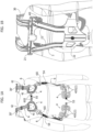
- the frame 2 constitutes the component of the system to which the function unit is connected, and to which the forces generated by the function unit are transmitted, while the contact units 4 constitute the components of the system through which the forces transmitted from the function unit to the frame 2 are discharged onto the operator's body.
- These contact units are designed to be positioned on the front and rear sides of the operator's rib cage, to mainly discharge the angular moments transmitted to the frame 2; and on the hips, to mainly discharge the vertical forces transmitted to the frame 2.
- the regions of the operator's body not in contact with the units 4 are, therefore, not involved (at least not directly) in supporting the loads and forces generated by the function unit.
- each contact unit is formed by at least two mutually movable and elastically connected supports, so that it is able, on one hand, to adapt to the conformation of the body of different operators, and on the other hand, to follow the movements of the operator's body and to elastically contrast the forces transmitted by the frame 2.
- the interface system 10 is generally comfortable to wear, and capable of relieving the neck, the trapezius muscle regions, the shoulders, and the abdominal region of the operator from loads, which are extremely sensitive parts to prolonged exertion.
- the frame 2 comprises an upper portion 21, intended to be positioned at the scapular region of the operator, and a lower portion 22, intended to be positioned at the lumbar or lumbosacral region of the operator.
- the frame 2 also comprises two side portions 23, which extend parallelly to the main direction K and connect the upper portion 21 and the lower portion 22 to each other.
- the two portions 23 are spaced apart along a direction transverse to the direction K, so as to arrange themselves on opposite sides of the operator's vertebral column, thus leaving this region of the body free.
- the frame 2 has a rigid structure and can be made of metal, for example, aluminum, or of a rigid plastic material, for example, PLA (polylactic acid), optionally loaded with carbon, or even made of wood.
- PLA polylactic acid
- the two supports 41, 42 of the contact units 4 may be made of plastic material, for example nylon, PET or PLA.
- the support 41 which is intended to come into contact with the body of the operator, is formed of a semi-rigid and perforated plate over a prevalent area of its extension.
- the holes obtained thereon have the function of accentuating the elastic behavior of the plate, and, on the other hand, of allowing the parts of the operator's body with which the plate comes into contact to breathe.
- the support 42 of the contact units 4 is also formed of a plate, of which the structure may be rigid or semi-rigid.
- One or more attachment points 42A are arranged on this plate 42 for connecting the unit 4 to the frame 2 or to the flexible elements 6.
- the attachment points in question can be of various types.
- the plate 42 may have one or more slots 42A for fastening these elements.
- the plate 42 may, instead, have one or more holes (not illustrated) for fixing to the frame 2 by means of screws or other fastening members of an equivalent type.
- the elastic bodies 43 consist of substantially tubular bodies, preferably made of rubber, which are arranged with their axis oriented transversely to the supports 41 and 42. These bodies are designed to be squeezed due to a change in position and/or orientation between the two supports 41 and 42, and operate on these with an elastic action to return to their extended condition.
- the number and distribution of these bodies between the two supports 41 and 42 are chosen so that the loads transmitted to the supports 42 are discharged over an extended area of the supports 41 and, consequently, over an area of equal extension of the body of the operator.
- the bodies 43 may also contain a gas under pressure to accentuate their elastic behavior.
- the contact units 4 may, on the other hand, comprise one or more elastic bodies consisting of closed cell foams or flexible reticular structures.
- Figures 4A and 4B illustrate two examples wherein the contact unit 4 comprises a single elastic body, in the shape of a parallelepiped, which - in the example of Figure 4A - consists of a closed cell foam, and - in the example of Figure 4B - consists of a flexible reticular structure.
- the materials used can be polymeric materials, for example, rubbers, polyurethane, polyamide, etc.
- the contact units 4III constitute a belt configured for wrapping around the operator's hips, having a chain-type structure.
- the different units 4III are connected to each other through the respective plates 42 so as to be able to rotate and vary their orientation with respect to the adjacent units.
- this connection can be made through flexible elements 52 such as, for example, tapes.
- each contact unit 4III can be connected to the adjacent unit by means of a hinge, which rotatably connects the relative plates 42 of the two contact units.
- the contact units 4III differ from each other according to the part of the hips on which they are intended to come into contact.
- the series of contact units 4III comprises, in particular, two contact units 4III(1), which are intended to be positioned on the rear side of the hips, in symmetrical positions with respect to the vertebral column, and preferably at the level of the iliac-lumbar region.
- the series in question also comprises two contact units 4III(2) which are, instead, intended to be positioned on the front side of the hips, always in symmetrical positions with respect to the vertebral column, and at the level of the lower abdomen.
- the contact units 4III(2) are distinguished from the contact units 4III(1) in that they each provide a single support 42, which is common to two supports 41; each of the two supports 41 is connected to the support 42 by means of a respective elastic body 43.
- the support 42 has a longitudinal extension intended to orient itself along the circumference of the operator's hips, and is equipped with a semi-rigid structure so that it can bend, adapting to the shape of the operator's body.
- the corresponding contact units 4III(1) and 4III(2) are arranged over the iliac crest of the pelvis.
- the size and number of supports 41 carried by the single support 42 may vary according to the requirements of the specific applications, regarding both the contact units 4III(1) and the contact units 4III(2)
- the contact units 4III instead, all have the same structure in which each support 42 carries a single support 41.
- the individual contact units preferably have small dimensions to engage a restricted area of the operator's body.
- the series constituted by the contact units has a significantly higher number than the embodiment illustrated, so that all the units together, in a discretized way, still cover a prevalent part of the circumference of the operator's hips.
- the series of contact units 4III is designed to adapt to the shape of the hips of different operators, always remaining wrapped around and adherent thereto, and to distribute the loads along an extended and prevalent part of the circumference of the hips.
- the series of flexible elements 52 that connect the supports 42 of the different contact units 4III(1) and 4III(2) also includes releasable connecting members 53 (for example, clip fasteners of the type used for backpacks) to close the system 10 on the operator's hips.
- releasable connecting members 53 for example, clip fasteners of the type used for backpacks
- the series of contact units 4I comprises only two contact units, which are arranged to be positioned on the front side of the operator's rib cage, preferably in symmetrical positions with respect to the vertebral column.
- the series of contact units 4II comprises only two contact units, which are fixed to the frame 2 and are arranged to be positioned on the scapular regions of the operator, always in symmetrical positions with respect to the vertebral column.
- the contact units 4I and 4II may, instead, be single or consisting of a number greater than two, based on the requirements of specific applications.
- the worn system 10 is designed to leave the region along the vertebral column free on the rear side of the operator's torso, since, as seen, the contact units 4II and 4III(1) and the side portions 23 of frame 2 are all positioned, symmetrically, on opposite sides of this region.
- the flexible elements 6 connect the contact units 4I to the frame 2 and, in general, are arranged to create the fastening of the system 10 - as a whole - to the body of the operator.
- the series of elements 6 comprises elements 6I, which connect the two contact units 4I to the upper portion 21 of the frame 2, and two elements 6II, which connect the same contact units to the lower portion 22 of the frame.
- the elements 61 and 6II constitute shoulder straps.
- the elements 6I and 6II may be connected to the contact units 4I and to the frame 2, with the possibility of varying their length between these units, and the upper and lower portions 21, 22 of the frame 2, in order to provide an adjustment of the system, to adapt it to the operator's build.
- the elements 6II may include releasable connecting members 54 to determine their opening in order to facilitate putting on or taking off the system.
- Two additional elements 6III are each connected to a respective contact unit 4I, and are arranged with releasable connecting members 55 (for example, clip fasteners of the type used for backpacks, hooks, Velcro, etc.) to connect the two elements 6III and, in this way, to close the system 10 on the operator's torso.
- releasable connecting members 55 for example, clip fasteners of the type used for backpacks, hooks, Velcro, etc.
- the flexible elements 6I, 6II and 6III may be constituted by belts or tapes, made, for example, of fabric or non-woven fabric.
- the system 10 comprises two spacer elements 30, which are attached to the upper portion 21 of the frame 2 and extend beyond it, in an opposite direction with respect to the side portions 23, in such a way that, in the worn condition of the system, these elements rise above the regions of the trapezius and clavicular muscles, and their ends 30' are positioned at a distance from these regions.
- the flexible elements 6I are connected to the ends 30' of the elements 30, and not directly to the upper portion 21 of the frame 2.
- the spacer elements 30 may be made of metal or of plastic material, like the frame 2.
- the spacer elements 30 may be formed of appendages of the same frame 2.
- the series of contact units 4III is connected to the lower portion 22 of the frame 2 so that the vertical forces transmitted by the frame are discharged onto the hips of the operator.
- this connection is made between the rear portion 22 and the two contact units 4III(1), which are arranged to be positioned on the iliac-lumbar regions.
- the two units 4III(1) are connected to the portion 22 through a hinge 70 that defines a rotation axis I intended, in the worn condition of the system 10, to be positioned horizontally, in a sagittal plane of the operator, to allow the contact units to vary their orientation according to the orientation of the operator's hips.
- Figure 7 schematically illustrates how the two contact units 4III(1) are positioned differently around the rotation axis I, depending on the different posture of the operator's pelvis.
- this Figure shows the variations of the angle ⁇ which is defined between a direction parallel to the longitudinal axis of the operator and the direction wherein the bracket 72 carrying the two contact units 4III(1) is arranged.
- the two units 4III(1) are carried by a bracket 72 having a central portion 72A, connected to the portion 22 of the frame 2 through the hinge 70, from which side tabs 72B protrude (on opposite sides with respect to the direction K) to which the supports 42 of the contact units 4III(1) are fixed, for example by means of screws.
- the hinge 70 is equipped with a system designed to block the movement of the hinge and thus fix the two contact units 4III(1) in the orientation selected by the operator, after he has worn the interface system and made adjustments to suit his body size.
- this system comprises an adjustment member, for example, a screw 75, as in the illustrated embodiment, to facilitate adjustment of the position of the hinge by the operator.
- the hinge 70 is, instead, kept mobile even when the operator is wearing the system and is working, so that the two units 4III(1) can follow the movements of his hips.
- the two contact units 4III(1) are also adjustable in a position along the direction K of the frame 2, to provide the possibility of adjusting the distance between the series of contact units 4III and the series of contact units 4II, as a function of the height of the operator.
- the bracket 72 is - in turn - carried by a support 74, which can be fixed to the lower portion 22 in different positions along the direction K, through a position adjustment system.
- This system may be of various types and, in particular, can be arranged for continuous or discrete position adjustment.
- this system may provide two toothed portions 74A, 22A, which can be coupled in different relative positions along the direction K, and a clamping lever 76, or any other locking member of equivalent type, by means of which the two portions may be fixed in the relative position selected by the operator.
- the interface system described here has a simple and essential structure, wherein, on the one hand, the frame 2, present only on the rear side of the operator's rib cage, provides the necessary rigidity to resist the stresses transmitted by the function unit to the system, and, on the other hand, the contact units 4 provide the points - the only ones - through which the system unloads the forces on the operator's body.
- the units in question consist of two supports, elastically connected together, and are, instead, completely free of padding materials (for example, sponges, rubber, etc.), which are, conversely, very widespread in the prior art.
- padding materials for example, sponges, rubber, etc.
- this structure of the contact units 4 offers a series of further advantages, such as not absorbing the operator's sweat, being easily washable, and that the system is suitable for outdoor use.
- the contact units are, moreover, more durable with respect to padded elements that tend to deform permanently, over time.
- the supports 41 of the contact units 4 can - in any case - be covered with caps made of soft material, for example, of the disposable type.
- the interface system 10 may be used in combination with any function unit.
- the interface system described here may be advantageously used for a system for assisting exertion of efforts, of the type described in the application PCT WO2019016629 .
Landscapes
- Engineering & Computer Science (AREA)
- Health & Medical Sciences (AREA)
- Mechanical Engineering (AREA)
- Robotics (AREA)
- Rehabilitation Therapy (AREA)
- Pain & Pain Management (AREA)
- Animal Behavior & Ethology (AREA)
- General Health & Medical Sciences (AREA)
- Public Health (AREA)
- Veterinary Medicine (AREA)
- Physical Education & Sports Medicine (AREA)
- Life Sciences & Earth Sciences (AREA)
- Epidemiology (AREA)
- Human Computer Interaction (AREA)
- Orthopedics, Nursing, And Contraception (AREA)
- Professional, Industrial, Or Sporting Protective Garments (AREA)
- Invalid Beds And Related Equipment (AREA)
- Manipulator (AREA)
- Prostheses (AREA)
Description
- The present invention relates to a system for interfacing with an operator's body for a function unit.
- These systems are intended to be coupled with a generic function unit, for example, a piece of equipment, a transport unit, etc., and are worn by the operator to perform the function of discharging the forces generated by the unit on the body of the operator, usually relieving the arms of the operator of part of the efforts.
- Interface systems of this type are becoming more and more widespread in the various work areas, for example, in industry, construction sites, the agricultural sector, etc., following the trend, which has been in place for some time now, to provide increasingly more stringent requirements for the working conditions of workers.
- However, known interface systems have various drawbacks, including the fact that - on average - they are uncomfortable; they cause discomfort or even pain following prolonged use; they make the operator sweat; and they are unsuitable for use by several people, to name the main drawbacks that are of interest for this discussion.
-
US2016/000212A1 ,CN109333505A ,KR20110101656A DE102018123017B3 disclose prior art representing certain technical background. DocumentUS 2016/000212 A1 discloses a backpack frame device, comprising supports for the back and the front side of the operator's thoracic region and springs interposed between the supports and the frame. - In this context, the present invention aims to provide an improved interface system with respect to known systems, in particular, one that overcomes one or more of the aforesaid drawbacks.
- This object is achieved through an interface system having the characteristics referred to in
claim 1. - The claims form an integral part of the technical disclosure provided here in relation to the invention.
- Further characteristics and advantages of the invention will become evident from the description that follows with reference to the attached drawings, provided purely by way of non-limiting example, wherein:
-
Figures 1A and 1B represent a preferred embodiment of the interface system described here, according to a front view and a rear view, respectively; -
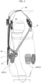
Figure 2 represents a side view of the interface system ofFigure 1 ; -
Figures 3A, 3B and 3C represent a component of the interface system ofFigure 1 according to three-quarter views, respectively, from above, from below and from the side; -
Figures 4A and 4B represent variants of the component ofFigures 3A, 3B and 3C ; -
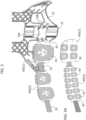
Figure 5 represents a detail of the interface system ofFigure 1 partially disassembled; -
Figure 5A represents a variant of the system ofFigure 1 ; -
Figure 6 represents a detail of the system ofFigure 1 ; -
Figure 7 illustrates a series of examples wherein the system described here is worn by operators with different postures and builds. - In the following description, various specific details are illustrated aimed at a thorough understanding of the embodiments. The embodiments may be implemented without one or more of the specific details, or with other methods, components, materials, etc. In other cases, known structures, materials or operations are not shown or described in detail to avoid obscuring various aspects of the embodiments.
- The references used here are only for convenience and do not, therefore, define the field of protection or the scope of the embodiments.
- The solution described here relates to a system for interfacing with an operator's body for a function unit. This term here refers to any unit arranged for carrying out a given function or operation. It can, for example, be a tool, a piece of equipment, an apparatus, a device, etc. The function or operation may be of any type and for any area of activity, for example, industry, construction site, agricultural sector, trade, etc.
- The interface system in question is, in particular, intended for those applications wherein the function unit is arranged to be carried by an operator, and performs the function of discharging the forces generated by the unit onto the operator's body.
- In general, the interface system described here, indicated in the figures with the reference number 10, comprises:
- a
frame 2 intended to be positioned on the rear side of the operator's torso, and defining a main extension direction K which, in a worn condition of the system, is oriented parallelly to the longitudinal axis of the operator; - a plurality of
contact units 4, which are connected to theframe 2 and are intended to be brought into contact with the operator's torso and hips, - wherein this plurality of contact units comprises:
- a first series of
contact units 41 configured to position themselves on the front side of the operator's thoracic region; - a second series of contact units 4II configured to position themselves on the rear side of the operator's thoracic region; and
- a third series of contact units 4III configured to position themselves on the operator's hips;
- a first series of
- wherein each
contact unit 4 comprises a first and asecond support elastic body 43, which is interposed between the first and the second support, and which is deformable so as to allow position and/or orientation variations between thefirst support 41 and thesecond support 42; thefirst support 41 being intended to be brought into contact with the operator's body in the worn condition of the interface system;- a plurality of
flexible elements 6 for connecting the contact units 4I to theframe 2.
- a plurality of
- The
frame 2 constitutes the component of the system to which the function unit is connected, and to which the forces generated by the function unit are transmitted, while thecontact units 4 constitute the components of the system through which the forces transmitted from the function unit to theframe 2 are discharged onto the operator's body. - These contact units are designed to be positioned on the front and rear sides of the operator's rib cage, to mainly discharge the angular moments transmitted to the
frame 2; and on the hips, to mainly discharge the vertical forces transmitted to theframe 2. - Overall, the forces generated by the function unit are transmitted to the operator's body entirely or almost entirely by the
contact units 4. - The regions of the operator's body not in contact with the
units 4 are, therefore, not involved (at least not directly) in supporting the loads and forces generated by the function unit. - As indicated above, each contact unit is formed by at least two mutually movable and elastically connected supports, so that it is able, on one hand, to adapt to the conformation of the body of different operators, and on the other hand, to follow the movements of the operator's body and to elastically contrast the forces transmitted by the
frame 2. - Thanks to the characteristics indicated above, the interface system 10 is generally comfortable to wear, and capable of relieving the neck, the trapezius muscle regions, the shoulders, and the abdominal region of the operator from loads, which are extremely sensitive parts to prolonged exertion.
- With reference now to preferred embodiments of the system described here, the
frame 2 comprises anupper portion 21, intended to be positioned at the scapular region of the operator, and alower portion 22, intended to be positioned at the lumbar or lumbosacral region of the operator. - In preferred embodiments, as in the one illustrated, the
frame 2 also comprises twoside portions 23, which extend parallelly to the main direction K and connect theupper portion 21 and thelower portion 22 to each other. - The two
portions 23 are spaced apart along a direction transverse to the direction K, so as to arrange themselves on opposite sides of the operator's vertebral column, thus leaving this region of the body free. - The
frame 2 has a rigid structure and can be made of metal, for example, aluminum, or of a rigid plastic material, for example, PLA (polylactic acid), optionally loaded with carbon, or even made of wood. - With reference to
Figures 3A-3B , the two supports 41, 42 of thecontact units 4 may be made of plastic material, for example nylon, PET or PLA. - In preferred embodiments, as well as in the one illustrated, the
support 41, which is intended to come into contact with the body of the operator, is formed of a semi-rigid and perforated plate over a prevalent area of its extension. The holes obtained thereon have the function of accentuating the elastic behavior of the plate, and, on the other hand, of allowing the parts of the operator's body with which the plate comes into contact to breathe. - The
support 42 of thecontact units 4 is also formed of a plate, of which the structure may be rigid or semi-rigid. One or more attachment points 42A are arranged on thisplate 42 for connecting theunit 4 to theframe 2 or to theflexible elements 6. - The attachment points in question can be of various types. For example, as illustrated in
Figures 3A-3C , for connecting to aflexible element 6, theplate 42 may have one or more slots 42A for fastening these elements. - For connecting to the
frame 2, theplate 42 may, instead, have one or more holes (not illustrated) for fixing to theframe 2 by means of screws or other fastening members of an equivalent type. - In preferred embodiments, as well as in the one illustrated, the
elastic bodies 43 consist of substantially tubular bodies, preferably made of rubber, which are arranged with their axis oriented transversely to thesupports supports 42 are discharged over an extended area of thesupports 41 and, consequently, over an area of equal extension of the body of the operator. - In some embodiments, the
bodies 43 may also contain a gas under pressure to accentuate their elastic behavior. - In alternative embodiments, the
contact units 4 may, on the other hand, comprise one or more elastic bodies consisting of closed cell foams or flexible reticular structures. In this regard,Figures 4A and 4B illustrate two examples wherein thecontact unit 4 comprises a single elastic body, in the shape of a parallelepiped, which - in the example ofFigure 4A - consists of a closed cell foam, and - in the example ofFigure 4B - consists of a flexible reticular structure. The materials used can be polymeric materials, for example, rubbers, polyurethane, polyamide, etc. - With reference now to
Figure 5 , in preferred embodiments, as well as in the one illustrated, the contact units 4III constitute a belt configured for wrapping around the operator's hips, having a chain-type structure. In particular, the different units 4III are connected to each other through therespective plates 42 so as to be able to rotate and vary their orientation with respect to the adjacent units. In preferred embodiments, as well as in the one illustrated, this connection can be made throughflexible elements 52 such as, for example, tapes. - Alternatively, each contact unit 4III can be connected to the adjacent unit by means of a hinge, which rotatably connects the
relative plates 42 of the two contact units. - In preferred embodiments, as well as in the one illustrated, the contact units 4III differ from each other according to the part of the hips on which they are intended to come into contact.
- The series of contact units 4III comprises, in particular, two contact units 4III(1), which are intended to be positioned on the rear side of the hips, in symmetrical positions with respect to the vertebral column, and preferably at the level of the iliac-lumbar region.
- The series in question also comprises two contact units 4III(2) which are, instead, intended to be positioned on the front side of the hips, always in symmetrical positions with respect to the vertebral column, and at the level of the lower abdomen.
- The contact units 4III(2) are distinguished from the contact units 4III(1) in that they each provide a
single support 42, which is common to twosupports 41; each of the twosupports 41 is connected to thesupport 42 by means of a respectiveelastic body 43. Thesupport 42 has a longitudinal extension intended to orient itself along the circumference of the operator's hips, and is equipped with a semi-rigid structure so that it can bend, adapting to the shape of the operator's body. - Preferably, on each side of the vertebral column, the corresponding contact units 4III(1) and 4III(2) are arranged over the iliac crest of the pelvis.
- As illustrated in the variant of
Figure 5A , the size and number ofsupports 41 carried by thesingle support 42, may vary according to the requirements of the specific applications, regarding both the contact units 4III(1) and the contact units 4III(2) - In alternative embodiments, the contact units 4III, instead, all have the same structure in which each support 42 carries a
single support 41. In this case, preferably the individual contact units have small dimensions to engage a restricted area of the operator's body. On the other hand, the series constituted by the contact units has a significantly higher number than the embodiment illustrated, so that all the units together, in a discretized way, still cover a prevalent part of the circumference of the operator's hips. - In general, the series of contact units 4III is designed to adapt to the shape of the hips of different operators, always remaining wrapped around and adherent thereto, and to distribute the loads along an extended and prevalent part of the circumference of the hips.
- Preferably, the series of
flexible elements 52 that connect thesupports 42 of the different contact units 4III(1) and 4III(2), also includes releasable connecting members 53 (for example, clip fasteners of the type used for backpacks) to close the system 10 on the operator's hips. - Returning to
Figures 1A and 1B , in preferred embodiments, as well as in the one illustrated, the series of contact units 4I comprises only two contact units, which are arranged to be positioned on the front side of the operator's rib cage, preferably in symmetrical positions with respect to the vertebral column. - In preferred embodiments, as well as in the one illustrated, the series of contact units 4II comprises only two contact units, which are fixed to the
frame 2 and are arranged to be positioned on the scapular regions of the operator, always in symmetrical positions with respect to the vertebral column. - In alternative embodiments, the contact units 4I and 4II may, instead, be single or consisting of a number greater than two, based on the requirements of specific applications.
- It should be noted that the worn system 10 is designed to leave the region along the vertebral column free on the rear side of the operator's torso, since, as seen, the contact units 4II and 4III(1) and the
side portions 23 offrame 2 are all positioned, symmetrically, on opposite sides of this region. - The
flexible elements 6 connect the contact units 4I to theframe 2 and, in general, are arranged to create the fastening of the system 10 - as a whole - to the body of the operator. - In preferred embodiments, as well as in the one illustrated, the series of
elements 6 compriseselements 6I, which connect the two contact units 4I to theupper portion 21 of theframe 2, and two elements 6II, which connect the same contact units to thelower portion 22 of the frame. Overall, theelements 61 and 6II constitute shoulder straps. - The
elements 6I and 6II may be connected to the contact units 4I and to theframe 2, with the possibility of varying their length between these units, and the upper andlower portions frame 2, in order to provide an adjustment of the system, to adapt it to the operator's build. Optionally, the elements 6II may include releasable connectingmembers 54 to determine their opening in order to facilitate putting on or taking off the system. - Two additional elements 6III are each connected to a respective contact unit 4I, and are arranged with releasable connecting members 55 (for example, clip fasteners of the type used for backpacks, hooks, Velcro, etc.) to connect the two elements 6III and, in this way, to close the system 10 on the operator's torso.
- The
flexible elements 6I, 6II and 6III may be constituted by belts or tapes, made, for example, of fabric or non-woven fabric. - In preferred embodiments, as well as in the one illustrated, the system 10 comprises two
spacer elements 30, which are attached to theupper portion 21 of theframe 2 and extend beyond it, in an opposite direction with respect to theside portions 23, in such a way that, in the worn condition of the system, these elements rise above the regions of the trapezius and clavicular muscles, and their ends 30' are positioned at a distance from these regions. - The
flexible elements 6I are connected to the ends 30' of theelements 30, and not directly to theupper portion 21 of theframe 2. - In this way, they do not press on the trapezius muscles or on the collarbones, making the system particularly comfortable to wear.
- The
spacer elements 30 may be made of metal or of plastic material, like theframe 2. - In alternative embodiments, the
spacer elements 30 may be formed of appendages of thesame frame 2. - The series of contact units 4III is connected to the
lower portion 22 of theframe 2 so that the vertical forces transmitted by the frame are discharged onto the hips of the operator. - Preferably, this connection is made between the
rear portion 22 and the two contact units 4III(1), which are arranged to be positioned on the iliac-lumbar regions. - In preferred embodiments, as well as in the one illustrated, the two units 4III(1) are connected to the
portion 22 through ahinge 70 that defines a rotation axis I intended, in the worn condition of the system 10, to be positioned horizontally, in a sagittal plane of the operator, to allow the contact units to vary their orientation according to the orientation of the operator's hips. In this regard,Figure 7 schematically illustrates how the two contact units 4III(1) are positioned differently around the rotation axis I, depending on the different posture of the operator's pelvis. In particular, this Figure shows the variations of the angle δ which is defined between a direction parallel to the longitudinal axis of the operator and the direction wherein thebracket 72 carrying the two contact units 4III(1) is arranged. - In preferred embodiments, as well as in the one illustrated, the two units 4III(1) are carried by a
bracket 72 having acentral portion 72A, connected to theportion 22 of theframe 2 through thehinge 70, from whichside tabs 72B protrude (on opposite sides with respect to the direction K) to which thesupports 42 of the contact units 4III(1) are fixed, for example by means of screws. - In preferred embodiments, the
hinge 70 is equipped with a system designed to block the movement of the hinge and thus fix the two contact units 4III(1) in the orientation selected by the operator, after he has worn the interface system and made adjustments to suit his body size. Preferably, this system comprises an adjustment member, for example, ascrew 75, as in the illustrated embodiment, to facilitate adjustment of the position of the hinge by the operator. - In alternative embodiments, the
hinge 70 is, instead, kept mobile even when the operator is wearing the system and is working, so that the two units 4III(1) can follow the movements of his hips. - In preferred embodiments, as well as in the one illustrated, the two contact units 4III(1) are also adjustable in a position along the direction K of the
frame 2, to provide the possibility of adjusting the distance between the series of contact units 4III and the series of contact units 4II, as a function of the height of the operator. - In particular, in preferred embodiments, as well as in the one illustrated, the
bracket 72 is - in turn - carried by asupport 74, which can be fixed to thelower portion 22 in different positions along the direction K, through a position adjustment system. This system may be of various types and, in particular, can be arranged for continuous or discrete position adjustment. For example, this system may provide twotoothed portions - In view of the above, it is now clear how the interface system described here has a simple and essential structure, wherein, on the one hand, the
frame 2, present only on the rear side of the operator's rib cage, provides the necessary rigidity to resist the stresses transmitted by the function unit to the system, and, on the other hand, thecontact units 4 provide the points - the only ones - through which the system unloads the forces on the operator's body. - As seen, the units in question consist of two supports, elastically connected together, and are, instead, completely free of padding materials (for example, sponges, rubber, etc.), which are, conversely, very widespread in the prior art.
- Beyond the advantages already discussed above, this structure of the
contact units 4, totally devoid of absorbent materials, offers a series of further advantages, such as not absorbing the operator's sweat, being easily washable, and that the system is suitable for outdoor use. - The contact units thus made are, moreover, more durable with respect to padded elements that tend to deform permanently, over time. Moreover, where required, the
supports 41 of thecontact units 4 can - in any case - be covered with caps made of soft material, for example, of the disposable type. - Overall, the interface system described here is also extremely light.
- As mentioned above, the interface system 10 may be used in combination with any function unit.
- A specific application whereby the system described here may be particularly advantageous concerns the field of systems for assisting exertion of efforts (also called "exoskeletons"). In this regard, the interface system described here may be advantageously used for a system for assisting exertion of efforts, of the type described in the application
PCT WO2019016629 . - Of course, without prejudice to the principle of the invention, the details of construction and the embodiments may vary, even significantly, with respect to those illustrated here, purely by way of non-limiting example, without departing from the scope of the invention as defined by the attached claims.
Claims (17)
- A system for interfacing with an operator's body for a function unit, comprising:- a frame (2) intended to be positioned on the rear side of the operator's torso, and defining a main extension direction (K) which, in a worn condition of said system, is oriented parallelly to the longitudinal axis of the operator,- a plurality of contact units (4), which are connected to said frame (2) and, in the worn condition of said system, are intended to be brought into contact with the operator's torso and hips,wherein said plurality comprises:- a first contact unit or a first series of contact units (4I) configured to position themselves on the front side of the operator's thoracic region;- a second contact unit or a second series of contact units (4II) configured to position themselves on the rear side of the operator's thoracic region;- a third contact unit or a third series of contact units (4III) configured to position themselves on the operator's hips;wherein each contact unit comprises a first and a second support (41, 42), and at least one elastic body (43), which is interposed between said first and second support (41, 42), and which is deformable so as to allow position and/or orientation variations between said first and second supports (41, 42), said first support (41) being intended to be brought into contact with the operator's body in said worn condition of the interface system;- a plurality of flexible elements (6) for connecting to said frame (2) said first contact unit, or said first series of contact units (4I).
- A system according to claim 1, having such an arrangement of said flexible elements (6) and of said contact units (4) that, in said worn condition, the forces generated by said function unit are transmitted to the operator's body entirely or almost entirely by said contact units (4).
- A system according to claim 1 or 2, wherein said frame (2) comprises an upper portion (21) intended to be positioned at the height of the operator's scapula region, and a lower portion (22) intended to be positioned at the height of the operator's lumbar or lumbosacral region,wherein said second contact unit or said second series of contact units (4I) is mounted on said upper portion of said frame, andwherein said third contact unit or third series of contact units (4I) is mounted on said lower portion of said frame.
- A system according to claim 3, wherein said third contact unit (4III(1)) or said third series of contact units (4III(1)) is connected to said lower portion (22) in a rotatable manner about a rotation axis (I) intended, in the worn condition of said system, to be positioned horizontally, in a sagittal plane of the operator and at the height of the operator's lumbar or lumbosacral region.
- A system according to claims 3 or 4, wherein said third contact unit or said third series of contact units (4III(1)) is, furthermore, adjustable in position along said main extension direction (K), so as to enable regulation of the distance between said third contact unit, or said third series of contact units (4III), and said second contact unit, or said second series of contact units (4II).
- A system according to any one of the preceding claims, wherein said third series of contact units (4III) form a belt intended to wrap around the operator's hips in said worn condition of the system (10), wherein each unit (4III) is connected to the adjacent units in a rotatable manner so as to vary its own orientation with respect to these units.
- A system according to claim 6, wherein said third series comprises two rear contact units (4III(1)), which are symmetrically positioned with respect to the longitudinal direction (K) of said frame (2) and which are configured to be positioned on the lumboiliac regions of the operator's body, while leaving the lumbosacral region free.
- A system according to claims 6 or 7, wherein said third series comprises two front contact units (4III(2)), which are symmetrically positioned with respect to the direction (K) of said frame (2), and which are configured to be positioned at the height of the lower region of the abdomen.
- A system according to any one of the preceding claims, wherein, in each contact unit (4), said first and second supports (41, 42) are made of plastic,wherein said first support (41) is constituted by a semi-rigid plate, preferably perforated over a major area of its extension, andwherein said second support (42) is constituted by a rigid or semi-rigid plate, said plate (42) being provided with one or more connecting points (42A) for connecting the contact unit (4) to said frame (2) or to one of said flexible elements (6).
- A system according to claim 3, wherein said frame (2) comprises, furthermore, two side portions (23), which extend parallelly to said main direction (K) and join together the upper portion (21) and the lower portion (22), wherein said portions (23) are set at a distance from one another along a direction that is transversal to said main direction (K), so as to position themselves, in said worn condition of said system, at the opposite sides of the operator's vertebral column, while leaving this region of the body free.
- A system according to any one of the preceding claims, wherein said first series of contact units (4I) comprises two contact units only, which are configured to position themselves on the front side of the ribcage of the operator, preferably at symmetrical positions with respect to the vertebral column.
- A system according to any one of the preceding claims, wherein said second series of contact units (4II) comprises two contact units only, which are configured to position themselves on the operator's scapula regions, preferably at symmetrical positions with respect to the vertebral column.
- A system according to any one of the preceding claims, wherein said frame (2) is made of metal, preferably aluminum, or of a rigid plastic material, possibly a carbon-loaded material.
- A system according to claim 3, wherein said plurality of flexible elements (6) comprises one or more elements (6I) that connect said first contact unit, or said first series of contact units (4I), to said upper portion (21) of said frame (2), and one or more elements (6II) that connect said first contact unit, or said first series of contact units (4I), to said lower portion (22) of said frame (2).
- A system according to claim 12, comprising one or more additional elements (6III) that connect the contact units of said first series of contact units to one another, by means of releasable connecting members, for locking said system (10) over the operator's torso.
- A system according to any one of the preceding claims, wherein said flexible elements (6I, 6II, 6III) are constituted by belts or bands.
- A system according to any one of the preceding claims, wherein said frame (2) comprises an upper portion (21) intended to be positioned at the height of the operator's scapula regions, and a lower portion (22) intended to be positioned at the height of the operator's lumbar or lumbosacral region, and wherein said system comprises one or more spacer elements (30) provided on said frame (2), and connected to corresponding flexible elements (6I, 6II) of said plurality of flexible elements, which extend at least partially along said main direction (K), so that, in the worn condition of said system, said flexible elements (6I, 6II) connected to said spacer elements rise above the operator's trapezoidal muscles and clavicular regions, and keep themselves at a distance therefrom.
Priority Applications (1)
| Application Number | Priority Date | Filing Date | Title |
|---|---|---|---|
| RS20240375A RS65345B1 (en) | 2020-01-16 | 2020-12-17 | A system for interfacing with an operator s body for a function unit |
Applications Claiming Priority (1)
| Application Number | Priority Date | Filing Date | Title |
|---|---|---|---|
| IT202000000751 | 2020-01-16 |
Publications (2)
| Publication Number | Publication Date |
|---|---|
| EP3851087A1 EP3851087A1 (en) | 2021-07-21 |
| EP3851087B1 true EP3851087B1 (en) | 2024-01-10 |
Family
ID=70295784
Family Applications (1)
| Application Number | Title | Priority Date | Filing Date |
|---|---|---|---|
| EP20214950.6A Active EP3851087B1 (en) | 2020-01-16 | 2020-12-17 | A system for interfacing with an operator s body for a function unit |
Country Status (10)
| Country | Link |
|---|---|
| US (1) | US11717073B2 (en) |
| EP (1) | EP3851087B1 (en) |
| JP (1) | JP7495180B2 (en) |
| CN (1) | CN113134825B (en) |
| BR (1) | BR102020025522A2 (en) |
| CA (1) | CA3101443A1 (en) |
| ES (1) | ES2970352T3 (en) |
| MX (1) | MX2020013830A (en) |
| PL (1) | PL3851087T3 (en) |
| RS (1) | RS65345B1 (en) |
Families Citing this family (2)
| Publication number | Priority date | Publication date | Assignee | Title |
|---|---|---|---|---|
| WO2023183364A1 (en) * | 2022-03-22 | 2023-09-28 | Ossur Iceland Ehf | Interface for an exoskeleton |
| CN115553552A (en) * | 2022-06-17 | 2023-01-03 | 吴颖卓 | A detachable multifunctional back structure |
Family Cites Families (12)
| Publication number | Priority date | Publication date | Assignee | Title |
|---|---|---|---|---|
| US5904282A (en) * | 1996-08-14 | 1999-05-18 | K-2 Corporation | External frame backpack harness |
| SE9901556L (en) | 1999-04-30 | 2000-10-31 | Camp Scandinavia Ab | Adjustable back orthosis |
| US8182439B2 (en) * | 2007-01-12 | 2012-05-22 | Emerald Touch, Inc. | Individual body support system |
| KR101167825B1 (en) * | 2010-03-09 | 2012-07-26 | 이도관 | A knapsack that use frame and the frame for a knapsack |
| KR101494189B1 (en) | 2014-02-19 | 2015-02-17 | 이서원 | Apparatus for frame of rucksack |
| IT201600112089A1 (en) * | 2016-11-08 | 2018-05-08 | Emak Spa | Shoulder support for an engine |
| IT201700081177A1 (en) | 2017-07-18 | 2019-01-18 | Iuvo S R L | "Operator assistance assistance system" |
| US10342319B1 (en) * | 2018-09-05 | 2019-07-09 | King Saud University | Wearable load carrier |
| DE102018123017B3 (en) | 2018-09-19 | 2019-12-05 | FLY Mobility GmbH | Device for resilient coupling of two plates and backpack with such a device |
| CN209915276U (en) | 2018-10-19 | 2020-01-10 | 苏州科瓴精密机械科技有限公司 | Backpack type machine tool |
| CN109333505A (en) | 2018-10-22 | 2019-02-15 | 江苏集萃微纳自动化系统与装备技术研究所有限公司 | An upper limb support and fixation device worn on the back |
| CN110150841B (en) | 2019-07-03 | 2024-07-12 | 杨海 | Tilting backpack structure |
-
2020
- 2020-12-02 CA CA3101443A patent/CA3101443A1/en active Pending
- 2020-12-03 JP JP2020200680A patent/JP7495180B2/en active Active
- 2020-12-14 BR BR102020025522-3A patent/BR102020025522A2/en active Search and Examination
- 2020-12-16 MX MX2020013830A patent/MX2020013830A/en unknown
- 2020-12-17 RS RS20240375A patent/RS65345B1/en unknown
- 2020-12-17 ES ES20214950T patent/ES2970352T3/en active Active
- 2020-12-17 EP EP20214950.6A patent/EP3851087B1/en active Active
- 2020-12-17 PL PL20214950.6T patent/PL3851087T3/en unknown
- 2020-12-30 US US17/138,137 patent/US11717073B2/en active Active
-
2021
- 2021-01-15 CN CN202110055918.6A patent/CN113134825B/en active Active
Also Published As
| Publication number | Publication date |
|---|---|
| JP2021113383A (en) | 2021-08-05 |
| KR20210093169A (en) | 2021-07-27 |
| RS65345B1 (en) | 2024-04-30 |
| CN113134825B (en) | 2025-06-17 |
| BR102020025522A2 (en) | 2021-07-20 |
| CN113134825A (en) | 2021-07-20 |
| US11717073B2 (en) | 2023-08-08 |
| PL3851087T3 (en) | 2024-05-13 |
| ES2970352T3 (en) | 2024-05-28 |
| EP3851087A1 (en) | 2021-07-21 |
| JP7495180B2 (en) | 2024-06-04 |
| US20210219705A1 (en) | 2021-07-22 |
| MX2020013830A (en) | 2021-07-19 |
| CA3101443A1 (en) | 2021-07-16 |
Similar Documents
| Publication | Publication Date | Title |
|---|---|---|
| US10485690B2 (en) | Personal equipment suspension system with active lumbar support | |
| US10864102B2 (en) | Human interface device for exoskeleton apparatus | |
| US10617552B2 (en) | Thoracic lumbar sacral orthosis | |
| EP0735847B1 (en) | Derotating orthotic devices for the correction of scoliotic deformities | |
| US6893098B2 (en) | Chair mounted back support system | |
| US8235925B2 (en) | Back brace | |
| US7837639B2 (en) | Adjustable brace for correcting a forward lean | |
| US12097139B2 (en) | Posture and lifting orthotic | |
| WO1993018724A1 (en) | Back support system with interchangeable orthotic supports | |
| WO1994012125A1 (en) | Lumbosacral support releasably secured to stabilizing belt | |
| EP3851087A1 (en) | A system for interfacing with an operator s body for a function unit | |
| US20140074003A1 (en) | Posture and Lifting Orthotic | |
| US20110297721A1 (en) | Load bearing devices for human load bearing usages | |
| US20200276043A1 (en) | Trunk orthosis | |
| KR101807573B1 (en) | Multipurpose Function Neck supporting band | |
| KR102966630B1 (en) | A system for interfacing with an operator's body for a function unit | |
| US20240407938A1 (en) | Posture and Lifting Orthotic | |
| US20250312181A1 (en) | Upper body chassis | |
| JP3156477U (en) | Hip and back fatigue relief device | |
| US20120289874A1 (en) | Spinal Posture Brace | |
| US20250312182A1 (en) | Support configured to be worn by a user |
Legal Events
| Date | Code | Title | Description |
|---|---|---|---|
| PUAI | Public reference made under article 153(3) epc to a published international application that has entered the european phase |
Free format text: ORIGINAL CODE: 0009012 |
|
| STAA | Information on the status of an ep patent application or granted ep patent |
Free format text: STATUS: THE APPLICATION HAS BEEN PUBLISHED |
|
| AK | Designated contracting states |
Kind code of ref document: A1 Designated state(s): AL AT BE BG CH CY CZ DE DK EE ES FI FR GB GR HR HU IE IS IT LI LT LU LV MC MK MT NL NO PL PT RO RS SE SI SK SM TR |
|
| STAA | Information on the status of an ep patent application or granted ep patent |
Free format text: STATUS: REQUEST FOR EXAMINATION WAS MADE |
|
| 17P | Request for examination filed |
Effective date: 20220112 |
|
| RBV | Designated contracting states (corrected) |
Designated state(s): AL AT BE BG CH CY CZ DE DK EE ES FI FR GB GR HR HU IE IS IT LI LT LU LV MC MK MT NL NO PL PT RO RS SE SI SK SM TR |
|
| RIC1 | Information provided on ipc code assigned before grant |
Ipc: A45F 3/14 20060101ALN20230613BHEP Ipc: A45F 3/08 20060101ALI20230613BHEP Ipc: A45F 3/04 20060101ALI20230613BHEP Ipc: A61H 1/02 20060101AFI20230613BHEP |
|
| GRAP | Despatch of communication of intention to grant a patent |
Free format text: ORIGINAL CODE: EPIDOSNIGR1 |
|
| STAA | Information on the status of an ep patent application or granted ep patent |
Free format text: STATUS: GRANT OF PATENT IS INTENDED |
|
| INTG | Intention to grant announced |
Effective date: 20230802 |
|
| RIN1 | Information on inventor provided before grant (corrected) |
Inventor name: MORBIDELLI, MAURO Inventor name: SOLA, ANDREA FRANCESCO Inventor name: CINIELLO, FRANCESCO |
|
| GRAS | Grant fee paid |
Free format text: ORIGINAL CODE: EPIDOSNIGR3 |
|
| GRAA | (expected) grant |
Free format text: ORIGINAL CODE: 0009210 |
|
| STAA | Information on the status of an ep patent application or granted ep patent |
Free format text: STATUS: THE PATENT HAS BEEN GRANTED |
|
| AK | Designated contracting states |
Kind code of ref document: B1 Designated state(s): AL AT BE BG CH CY CZ DE DK EE ES FI FR GB GR HR HU IE IS IT LI LT LU LV MC MK MT NL NO PL PT RO RS SE SI SK SM TR |
|
| REG | Reference to a national code |
Ref country code: GB Ref legal event code: FG4D |
|
| REG | Reference to a national code |
Ref country code: CH Ref legal event code: EP |
|
| REG | Reference to a national code |
Ref country code: DE Ref legal event code: R096 Ref document number: 602020024153 Country of ref document: DE |
|
| REG | Reference to a national code |
Ref country code: IE Ref legal event code: FG4D |
|
| REG | Reference to a national code |
Ref country code: SE Ref legal event code: TRGR |
|
| REG | Reference to a national code |
Ref country code: LT Ref legal event code: MG9D |
|
| REG | Reference to a national code |
Ref country code: NL Ref legal event code: MP Effective date: 20240110 |
|
| REG | Reference to a national code |
Ref country code: ES Ref legal event code: FG2A Ref document number: 2970352 Country of ref document: ES Kind code of ref document: T3 Effective date: 20240528 |
|
| REG | Reference to a national code |
Ref country code: AT Ref legal event code: MK05 Ref document number: 1648335 Country of ref document: AT Kind code of ref document: T Effective date: 20240110 |
|
| PG25 | Lapsed in a contracting state [announced via postgrant information from national office to epo] |
Ref country code: NL Free format text: LAPSE BECAUSE OF FAILURE TO SUBMIT A TRANSLATION OF THE DESCRIPTION OR TO PAY THE FEE WITHIN THE PRESCRIBED TIME-LIMIT Effective date: 20240110 |
|
| PG25 | Lapsed in a contracting state [announced via postgrant information from national office to epo] |
Ref country code: NL Free format text: LAPSE BECAUSE OF FAILURE TO SUBMIT A TRANSLATION OF THE DESCRIPTION OR TO PAY THE FEE WITHIN THE PRESCRIBED TIME-LIMIT Effective date: 20240110 |
|
| PG25 | Lapsed in a contracting state [announced via postgrant information from national office to epo] |
Ref country code: IS Free format text: LAPSE BECAUSE OF FAILURE TO SUBMIT A TRANSLATION OF THE DESCRIPTION OR TO PAY THE FEE WITHIN THE PRESCRIBED TIME-LIMIT Effective date: 20240510 |
|
| PG25 | Lapsed in a contracting state [announced via postgrant information from national office to epo] |
Ref country code: LT Free format text: LAPSE BECAUSE OF FAILURE TO SUBMIT A TRANSLATION OF THE DESCRIPTION OR TO PAY THE FEE WITHIN THE PRESCRIBED TIME-LIMIT Effective date: 20240110 |
|
| PG25 | Lapsed in a contracting state [announced via postgrant information from national office to epo] |
Ref country code: GR Free format text: LAPSE BECAUSE OF FAILURE TO SUBMIT A TRANSLATION OF THE DESCRIPTION OR TO PAY THE FEE WITHIN THE PRESCRIBED TIME-LIMIT Effective date: 20240411 |
|
| PG25 | Lapsed in a contracting state [announced via postgrant information from national office to epo] |
Ref country code: HR Free format text: LAPSE BECAUSE OF FAILURE TO SUBMIT A TRANSLATION OF THE DESCRIPTION OR TO PAY THE FEE WITHIN THE PRESCRIBED TIME-LIMIT Effective date: 20240110 |
|
| PG25 | Lapsed in a contracting state [announced via postgrant information from national office to epo] |
Ref country code: AT Free format text: LAPSE BECAUSE OF FAILURE TO SUBMIT A TRANSLATION OF THE DESCRIPTION OR TO PAY THE FEE WITHIN THE PRESCRIBED TIME-LIMIT Effective date: 20240110 |
|
| PG25 | Lapsed in a contracting state [announced via postgrant information from national office to epo] |
Ref country code: NO Free format text: LAPSE BECAUSE OF FAILURE TO SUBMIT A TRANSLATION OF THE DESCRIPTION OR TO PAY THE FEE WITHIN THE PRESCRIBED TIME-LIMIT Effective date: 20240410 Ref country code: LT Free format text: LAPSE BECAUSE OF FAILURE TO SUBMIT A TRANSLATION OF THE DESCRIPTION OR TO PAY THE FEE WITHIN THE PRESCRIBED TIME-LIMIT Effective date: 20240110 Ref country code: IS Free format text: LAPSE BECAUSE OF FAILURE TO SUBMIT A TRANSLATION OF THE DESCRIPTION OR TO PAY THE FEE WITHIN THE PRESCRIBED TIME-LIMIT Effective date: 20240510 Ref country code: HR Free format text: LAPSE BECAUSE OF FAILURE TO SUBMIT A TRANSLATION OF THE DESCRIPTION OR TO PAY THE FEE WITHIN THE PRESCRIBED TIME-LIMIT Effective date: 20240110 Ref country code: GR Free format text: LAPSE BECAUSE OF FAILURE TO SUBMIT A TRANSLATION OF THE DESCRIPTION OR TO PAY THE FEE WITHIN THE PRESCRIBED TIME-LIMIT Effective date: 20240411 Ref country code: BG Free format text: LAPSE BECAUSE OF FAILURE TO SUBMIT A TRANSLATION OF THE DESCRIPTION OR TO PAY THE FEE WITHIN THE PRESCRIBED TIME-LIMIT Effective date: 20240110 Ref country code: AT Free format text: LAPSE BECAUSE OF FAILURE TO SUBMIT A TRANSLATION OF THE DESCRIPTION OR TO PAY THE FEE WITHIN THE PRESCRIBED TIME-LIMIT Effective date: 20240110 |
|
| PG25 | Lapsed in a contracting state [announced via postgrant information from national office to epo] |
Ref country code: PT Free format text: LAPSE BECAUSE OF FAILURE TO SUBMIT A TRANSLATION OF THE DESCRIPTION OR TO PAY THE FEE WITHIN THE PRESCRIBED TIME-LIMIT Effective date: 20240510 |
|
| PG25 | Lapsed in a contracting state [announced via postgrant information from national office to epo] |
Ref country code: PT Free format text: LAPSE BECAUSE OF FAILURE TO SUBMIT A TRANSLATION OF THE DESCRIPTION OR TO PAY THE FEE WITHIN THE PRESCRIBED TIME-LIMIT Effective date: 20240510 Ref country code: LV Free format text: LAPSE BECAUSE OF FAILURE TO SUBMIT A TRANSLATION OF THE DESCRIPTION OR TO PAY THE FEE WITHIN THE PRESCRIBED TIME-LIMIT Effective date: 20240110 |
|
| PG25 | Lapsed in a contracting state [announced via postgrant information from national office to epo] |
Ref country code: DK Free format text: LAPSE BECAUSE OF FAILURE TO SUBMIT A TRANSLATION OF THE DESCRIPTION OR TO PAY THE FEE WITHIN THE PRESCRIBED TIME-LIMIT Effective date: 20240110 |
|
| REG | Reference to a national code |
Ref country code: DE Ref legal event code: R097 Ref document number: 602020024153 Country of ref document: DE |
|
| PG25 | Lapsed in a contracting state [announced via postgrant information from national office to epo] |
Ref country code: SM Free format text: LAPSE BECAUSE OF FAILURE TO SUBMIT A TRANSLATION OF THE DESCRIPTION OR TO PAY THE FEE WITHIN THE PRESCRIBED TIME-LIMIT Effective date: 20240110 |
|
| PG25 | Lapsed in a contracting state [announced via postgrant information from national office to epo] |
Ref country code: CZ Free format text: LAPSE BECAUSE OF FAILURE TO SUBMIT A TRANSLATION OF THE DESCRIPTION OR TO PAY THE FEE WITHIN THE PRESCRIBED TIME-LIMIT Effective date: 20240110 Ref country code: EE Free format text: LAPSE BECAUSE OF FAILURE TO SUBMIT A TRANSLATION OF THE DESCRIPTION OR TO PAY THE FEE WITHIN THE PRESCRIBED TIME-LIMIT Effective date: 20240110 |
|
| PG25 | Lapsed in a contracting state [announced via postgrant information from national office to epo] |
Ref country code: SK Free format text: LAPSE BECAUSE OF FAILURE TO SUBMIT A TRANSLATION OF THE DESCRIPTION OR TO PAY THE FEE WITHIN THE PRESCRIBED TIME-LIMIT Effective date: 20240110 |
|
| PG25 | Lapsed in a contracting state [announced via postgrant information from national office to epo] |
Ref country code: SM Free format text: LAPSE BECAUSE OF FAILURE TO SUBMIT A TRANSLATION OF THE DESCRIPTION OR TO PAY THE FEE WITHIN THE PRESCRIBED TIME-LIMIT Effective date: 20240110 Ref country code: SK Free format text: LAPSE BECAUSE OF FAILURE TO SUBMIT A TRANSLATION OF THE DESCRIPTION OR TO PAY THE FEE WITHIN THE PRESCRIBED TIME-LIMIT Effective date: 20240110 Ref country code: RO Free format text: LAPSE BECAUSE OF FAILURE TO SUBMIT A TRANSLATION OF THE DESCRIPTION OR TO PAY THE FEE WITHIN THE PRESCRIBED TIME-LIMIT Effective date: 20240110 Ref country code: EE Free format text: LAPSE BECAUSE OF FAILURE TO SUBMIT A TRANSLATION OF THE DESCRIPTION OR TO PAY THE FEE WITHIN THE PRESCRIBED TIME-LIMIT Effective date: 20240110 Ref country code: DK Free format text: LAPSE BECAUSE OF FAILURE TO SUBMIT A TRANSLATION OF THE DESCRIPTION OR TO PAY THE FEE WITHIN THE PRESCRIBED TIME-LIMIT Effective date: 20240110 Ref country code: CZ Free format text: LAPSE BECAUSE OF FAILURE TO SUBMIT A TRANSLATION OF THE DESCRIPTION OR TO PAY THE FEE WITHIN THE PRESCRIBED TIME-LIMIT Effective date: 20240110 |
|
| PLBE | No opposition filed within time limit |
Free format text: ORIGINAL CODE: 0009261 |
|
| STAA | Information on the status of an ep patent application or granted ep patent |
Free format text: STATUS: NO OPPOSITION FILED WITHIN TIME LIMIT |
|
| 26N | No opposition filed |
Effective date: 20241011 |
|
| PG25 | Lapsed in a contracting state [announced via postgrant information from national office to epo] |
Ref country code: SI Free format text: LAPSE BECAUSE OF FAILURE TO SUBMIT A TRANSLATION OF THE DESCRIPTION OR TO PAY THE FEE WITHIN THE PRESCRIBED TIME-LIMIT Effective date: 20240110 |
|
| PG25 | Lapsed in a contracting state [announced via postgrant information from national office to epo] |
Ref country code: MC Free format text: LAPSE BECAUSE OF FAILURE TO SUBMIT A TRANSLATION OF THE DESCRIPTION OR TO PAY THE FEE WITHIN THE PRESCRIBED TIME-LIMIT Effective date: 20240110 |
|
| REG | Reference to a national code |
Ref country code: CH Ref legal event code: PL |
|
| PG25 | Lapsed in a contracting state [announced via postgrant information from national office to epo] |
Ref country code: LU Free format text: LAPSE BECAUSE OF NON-PAYMENT OF DUE FEES Effective date: 20241217 |
|
| PG25 | Lapsed in a contracting state [announced via postgrant information from national office to epo] |
Ref country code: FI Free format text: LAPSE BECAUSE OF FAILURE TO SUBMIT A TRANSLATION OF THE DESCRIPTION OR TO PAY THE FEE WITHIN THE PRESCRIBED TIME-LIMIT Effective date: 20240110 |
|
| PG25 | Lapsed in a contracting state [announced via postgrant information from national office to epo] |
Ref country code: CH Free format text: LAPSE BECAUSE OF NON-PAYMENT OF DUE FEES Effective date: 20241231 |
|
| PG25 | Lapsed in a contracting state [announced via postgrant information from national office to epo] |
Ref country code: IE Free format text: LAPSE BECAUSE OF NON-PAYMENT OF DUE FEES Effective date: 20241217 |
|
| PGFP | Annual fee paid to national office [announced via postgrant information from national office to epo] |
Ref country code: GB Payment date: 20251223 Year of fee payment: 6 |
|
| PGFP | Annual fee paid to national office [announced via postgrant information from national office to epo] |
Ref country code: IT Payment date: 20251205 Year of fee payment: 6 |
|
| PGFP | Annual fee paid to national office [announced via postgrant information from national office to epo] |
Ref country code: FR Payment date: 20251223 Year of fee payment: 6 |
|
| PGFP | Annual fee paid to national office [announced via postgrant information from national office to epo] |
Ref country code: TR Payment date: 20251127 Year of fee payment: 6 |
|
| PGFP | Annual fee paid to national office [announced via postgrant information from national office to epo] |
Ref country code: SE Payment date: 20251222 Year of fee payment: 6 |
|
| PGFP | Annual fee paid to national office [announced via postgrant information from national office to epo] |
Ref country code: PL Payment date: 20251121 Year of fee payment: 6 |
|
| PGFP | Annual fee paid to national office [announced via postgrant information from national office to epo] |
Ref country code: RS Payment date: 20251126 Year of fee payment: 6 |
|
| PGFP | Annual fee paid to national office [announced via postgrant information from national office to epo] |
Ref country code: ES Payment date: 20260122 Year of fee payment: 6 |
|
| PGFP | Annual fee paid to national office [announced via postgrant information from national office to epo] |
Ref country code: DE Payment date: 20251229 Year of fee payment: 6 |
|
| PGFP | Annual fee paid to national office [announced via postgrant information from national office to epo] |
Ref country code: BE Payment date: 20260109 Year of fee payment: 6 |
|
| PG25 | Lapsed in a contracting state [announced via postgrant information from national office to epo] |
Ref country code: CY Free format text: LAPSE BECAUSE OF FAILURE TO SUBMIT A TRANSLATION OF THE DESCRIPTION OR TO PAY THE FEE WITHIN THE PRESCRIBED TIME-LIMIT Effective date: 20240110 |