EP3850282B1 - Refrigerant leak detection system - Google Patents
Refrigerant leak detection system Download PDFInfo
- Publication number
- EP3850282B1 EP3850282B1 EP19769687.5A EP19769687A EP3850282B1 EP 3850282 B1 EP3850282 B1 EP 3850282B1 EP 19769687 A EP19769687 A EP 19769687A EP 3850282 B1 EP3850282 B1 EP 3850282B1
- Authority
- EP
- European Patent Office
- Prior art keywords
- sensor
- housing
- fluid flow
- refrigeration unit
- evaporator
- Prior art date
- Legal status (The legal status is an assumption and is not a legal conclusion. Google has not performed a legal analysis and makes no representation as to the accuracy of the status listed.)
- Active
Links
Images



Classifications
-
- F—MECHANICAL ENGINEERING; LIGHTING; HEATING; WEAPONS; BLASTING
- F25—REFRIGERATION OR COOLING; COMBINED HEATING AND REFRIGERATION SYSTEMS; HEAT PUMP SYSTEMS; MANUFACTURE OR STORAGE OF ICE; LIQUEFACTION SOLIDIFICATION OF GASES
- F25B—REFRIGERATION MACHINES, PLANTS OR SYSTEMS; COMBINED HEATING AND REFRIGERATION SYSTEMS; HEAT PUMP SYSTEMS
- F25B49/00—Arrangement or mounting of control or safety devices
- F25B49/005—Arrangement or mounting of control or safety devices of safety devices
-
- B—PERFORMING OPERATIONS; TRANSPORTING
- B60—VEHICLES IN GENERAL
- B60H—ARRANGEMENTS OF HEATING, COOLING, VENTILATING OR OTHER AIR-TREATING DEVICES SPECIALLY ADAPTED FOR PASSENGER OR GOODS SPACES OF VEHICLES
- B60H1/00—Heating, cooling or ventilating devices
- B60H1/32—Cooling devices
- B60H1/3204—Cooling devices using compression
- B60H1/3225—Cooling devices using compression characterised by safety arrangements, e.g. compressor anti-seizure means or by signalling devices
-
- B—PERFORMING OPERATIONS; TRANSPORTING
- B60—VEHICLES IN GENERAL
- B60H—ARRANGEMENTS OF HEATING, COOLING, VENTILATING OR OTHER AIR-TREATING DEVICES SPECIALLY ADAPTED FOR PASSENGER OR GOODS SPACES OF VEHICLES
- B60H1/00—Heating, cooling or ventilating devices
- B60H1/32—Cooling devices
- B60H1/3204—Cooling devices using compression
- B60H1/3232—Cooling devices using compression particularly adapted for load transporting vehicles
-
- F—MECHANICAL ENGINEERING; LIGHTING; HEATING; WEAPONS; BLASTING
- F25—REFRIGERATION OR COOLING; COMBINED HEATING AND REFRIGERATION SYSTEMS; HEAT PUMP SYSTEMS; MANUFACTURE OR STORAGE OF ICE; LIQUEFACTION SOLIDIFICATION OF GASES
- F25D—REFRIGERATORS; COLD ROOMS; ICE-BOXES; COOLING OR FREEZING APPARATUS NOT OTHERWISE PROVIDED FOR
- F25D29/00—Arrangement or mounting of control or safety devices
- F25D29/003—Arrangement or mounting of control or safety devices for movable devices
-
- B—PERFORMING OPERATIONS; TRANSPORTING
- B60—VEHICLES IN GENERAL
- B60P—VEHICLES ADAPTED FOR LOAD TRANSPORTATION OR TO TRANSPORT, TO CARRY, OR TO COMPRISE SPECIAL LOADS OR OBJECTS
- B60P3/00—Vehicles adapted to transport, to carry or to comprise special loads or objects
- B60P3/20—Refrigerated goods vehicles
Definitions
- Exemplary embodiments pertain to the art of refrigerated systems, and more specifically, to transportation refrigeration units.
- Products may be shipped or stored within conditioned containers.
- These conditioned containers are specifically designed for conditioning an interior space with refrigerated air for an extended period of time.
- These refrigerated containers utilize a refrigeration unit that circulates cooled air inside the interior space through evaporator fans, which direct the air from the front of the container to the rear. Refrigerant from the refrigeration unit may leak inside the refrigerated container due to a component or system level failure.
- JP 2017 067392 A and WO 2018/147428 A1 both disclose refrigeration leak detection systems for refrigerated storage units.
- the former discloses arrangements of a refrigerant sensor in conjunction with housings, wind guides, and exhausts to minimize the effect of leaked refrigerant.
- the latter discloses arrangements of a refrigerant sensor that enable easy replacement of the sensor upon its breakdown.
- the transport refrigeration unit includes an evaporator arranged to receive a refrigerant; an evaporator fan spaced apart from the evaporator, the evaporator fan being arranged to move air past the evaporator; and a leak detection system, comprising: a sensor assembly having: a sensor housing defining a first fluid inlet, a leak sensor disposed within the sensor housing, the leak sensor being arranged to provide a signal indicative of a presence of the refrigerant within an interior space of the transport refrigeration unit, a collection housing, spaced apart from the sensor housing, the collection housing defining a second fluid inlet, and a conduit extending between and fluidly connected to the sensor housing and the collection housing, characterized in that the sensor assembly comprises: a first valve disposed opposite the first fluid inlet, the first valve being arranged to selectively facilitate a fluid flow between the collection housing and the leak sensor.
- the method includes: receiving a fluid flow within at least one of a sensor housing and a collection housing that is spaced apart from the sensor housing and fluidly connected to the sensor housing, wherein the sensor housing is provided with a first valve having a valve member movable between an open position and a closed position; directing the fluid flow towards a leak sensor disposed within the sensor housing; and outputting for display an indicator, responsive to a concentration of a refrigerant present within the fluid flow being greater than a threshold concentration; characterized in that: responsive to the fluid flow being received through a first fluid inlet of the sensor housing, the valve member is inhibited from moving away from the closed position or responsive to the fluid flow being received through a second fluid inlet of the collection housing and directed towards the first valve, the valve member is moved away from the closed position
- a refrigerated trailer, a refrigerated space, or a refrigerated container may be provided with a refrigeration system that provides conditioned air or cooled air to an interior space of the refrigerated trailer, the refrigerated space, or the refrigerated container.
- the refrigerant may leak into the interior space and may present a hazard should the concentration of the leaked refrigerant within the interior space exceed a threshold level.
- FIG. 1 Shown in FIG. 1 is an embodiment of a tractor trailer system 100.
- the tractor trailer system 100 includes a tractor 102 including an operator's compartment or cab 104 and also including an engine, which acts as the drive system of the tractor trailer system 100.
- a trailer 106 is coupled to the tractor 102.
- the trailer 106 is a refrigerated trailer 106 and includes a top wall 108, a directly opposed bottom wall 110, opposed side walls 112, and a front wall 114, with the front wall 114 being closest to the tractor 102.
- the trailer 106 further includes a door or doors (not shown) at a rear wall 116, opposite the front wall 114.
- the walls of the trailer 106 define a cargo compartment.
- the trailer 106 is configured to maintain a cargo 118 located inside the cargo compartment at a selected temperature through the use of a transport refrigeration unit 120 located on the trailer 106.
- the transport refrigeration unit 120 as shown in FIG. 1 , is located at or attached to the front wall 114.
- the transport refrigeration unit 120 includes a compressor 122, a condenser 124, a condenser fan 125, an expansion valve 126, an evaporator 128, and an evaporator fan 130, as well as other ancillary components.
- Airflow is circulated into and through the cargo compartment of the trailer 106 by means of the transport refrigeration unit 120.
- a return airflow 134 flows into the transport refrigeration unit 120 from the cargo compartment of the trailer 106 through a refrigeration unit inlet 136, and across the evaporator 128 via the evaporator fan 130, thus cooling the return airflow 134.
- the cooled return airflow 134 now referred to as supply airflow 138, is supplied into the cargo compartment of the trailer 106 through a refrigeration unit outlet 140, which in some embodiments is located near the top wall 108 of the trailer 106.
- the supply airflow 138 cools the cargo 118 in the cargo compartment of the trailer 106.
- a leak detection system 10 is also located within the transport refrigeration unit 120 and is arranged to detect the presence of refrigerant within the transport refrigeration unit 120.
- a controller 12 may be provided and in communication with the leak detection system 10 and/or the transportation refrigeration unit 120. The controller 12 may control various system components and may be implemented using a general-purpose microprocessor executing a computer program stored on a storage medium to perform the operations described herein.
- FIG. 1 depicts a tractor-trailer arraignment
- embodiments described herein may be used with other cargo compartments, such as those in containers.
- embodiments are not limited to tractor-trailer systems.
- the refrigerant, e.g. the first fluid, within the evaporator 128 may leak into an interior space of the trailer 106 or leak within the transport refrigeration unit 120.
- the refrigerant may fall or descend below the evaporator 128 and be located proximate a collection area 20, should the evaporator fan 130 be off and not operating because the refrigerant may have a density that is greater than air.
- the evaporator fan 130 may duct or flow the refrigerant away from the collection area 20 and towards the refrigeration unit outlet 140, potentially enabling the refrigerant to escape into the trailer 106.
- the leak detection system 10 is arranged to detect the presence of refrigerant within the transport refrigeration unit 120 before it escapes into the trailer 106, regardless of whether the evaporator fan 130 is on or off. Therefore, the leak detection system 10 is arranged to detect the presence of refrigerant either within the collection area 20 or in other areas, such as above the evaporator 128.
- the dual sensing locations facilitate a faster leak detection response time without having the refrigerant circulated throughout the trailer 106.
- the leak detection system 10 includes a sensor assembly 30 that is at least partially disposed within the transport refrigeration unit 120.
- the sensor assembly 30 includes a sensor housing 32, a collection housing 34, a conduit 36 that extends between the collection housing 34 and the sensor housing 32 to fluidly connect the sensor housing 32 to the collection housing 34, and the controller 12.
- the sensor housing 32 and the collection housing 34 are disposed on opposite sides of the evaporator 128 such that the evaporator 128 is disposed between the sensor housing 32 and the collection housing 34.
- the sensor housing 32 is disposed within the collection area 20.
- the sensor housing 32 includes a first fluid inlet 40, a receiving portion 42, and a first valve 44.
- the first fluid inlet 40, the receiving portion 42, and the first valve 44 may be integrated into the sensor housing 32 or all define the sensor housing 32.
- the first fluid inlet 40 extends between a first end 50 and the second end 52.
- the first end 50 may have a first cross-sectional form and the second end 52 may have a second cross-sectional form.
- the first cross-sectional form may be greater than the second cross-sectional form such that the first fluid inlet 40 has a funnel or frustoconical shape that directs a fluid flow from the first end 50 towards the second end 52 such that the fluid flow is directed towards the receiving portion 42.
- the receiving portion 42 extends from the second end 52 of the first fluid inlet 40.
- the receiving portion 42 is arranged to receive a leak sensor 60.
- the receiving portion 42 may be integrally formed with the leak sensor 60 such that the receiving portion 42 is a sensor housing of the leak sensor 60.
- the leak sensor 60 is arranged to provide a signal indicative of a concentration or the presence of refrigerant within the transport refrigeration unit 120 or that is received within the sensor housing 32 to the controller 12.
- the receiving portion 42 and the leak sensor 60 extends between the second end 52 of the first fluid inlet 40 and the first valve 44.
- the first valve 44 is disposed opposite the first fluid inlet 40 or spaced apart from the first fluid inlet 40 by the receiving portion 42.
- the first valve 44 is movable between a closed position and an open position to selectively facilitate a fluid flow from the collection housing 34 towards the leak sensor 60.
- the first valve 44 inhibits a fluid flow from the collection housing 34, through the conduit 36, towards the leak sensor 60 while in the closed position.
- the first valve 44 facilitates a fluid flow from the collection housing 34, through the conduit 36, to the leak sensor 60 while in the open position.
- the first valve 44 includes a valve member 70 that moves between the closed position and the open position such that the first valve 44 selectively facilitates the fluid flow between the collection housing 34 and the sensor housing 32.
- the valve member 70 is in a closed position while there is no fluid flow or fluid flow less than a threshold between the collection housing 34 and the sensor housing 32 via the conduit 36, as shown in FIG. 4 .
- a fluid flow 72 in a first direction that is received through the first fluid inlet 40 of the sensor housing 32 may inhibit the valve member 70 from moving away from the closed position.
- the fluid flow 72 in the first direction may be the descending of the refrigerant into the first fluid inlet 40.
- the valve member 70 moves towards the open position while there is fluid flow greater than a threshold between the collection housing 34 and the sensor housing 32 via the conduit 36, as shown in FIG. 5 .
- a fluid flow 74 in a second direction that is disposed opposite the first direction, that is received through the second fluid inlet 80 of collection housing 34 and directed through the conduit 36 towards the first valve 44, moves the valve member 70 away from the closed position.
- the fluid flow 74 in the second direction may be flow that flows through the collection housing 34 through the conduit 36 due to the operation of the evaporator fan 130.
- the collection housing 34 is spaced apart from the sensor housing 32.
- the collection housing 34 is disposed above the evaporator 128.
- the collection housing 34 includes a second fluid inlet 80.
- the second fluid inlet 80 extends between a first end 82 and the second end 84.
- the first end 82 may have a first cross-sectional form and the second end 84 may have a second cross-sectional form.
- the first cross-sectional form may be greater than the second cross-sectional form such that the second fluid inlet 80 has a general funnel or frustoconical shape that directs a fluid flow (e.g. the second fluid flow) from the first end 82 towards the second end 84 such that the fluid flow is directed towards the conduit 36 and towards the leak sensor 60.
- a fluid flow e.g. the second fluid flow
- the conduit 36 extends between and is fluidly connected to the sensor housing 32 and the collection housing 34.
- the conduit 36 extends between the second end 84 of the second fluid inlet 80 of the collection housing 34 and the first valve 44.
- the first valve 44 may be connected to the second end 84 of the second fluid inlet 80 such that the conduit 36 extends between the first valve 44 and the leak sensor 60.
- the controller 12 may be a controller that is provided with the refrigeration system or may be a controller dedicated to the leak detection system 10.
- the controller 12 is provided with input communication channels that are arranged to receive information, data, or signals from the leak sensor 60.
- the controller 12 is provided with output communication channels that are arranged to provide commands, signals, or data to a display or a monitoring system.
- the controller 12 is provided with at least one processor that is programmed to output for display an indicator based on information, data, or signals provided via the input communication channels and output commands via the output communication channels.
- a fluid flow enters the second fluid inlet 80 of the collection housing 34 and flows through the conduit 36 towards the sensor housing 32.
- the fluid flow may move the valve member 70 of the first valve 44 from the closed position towards the open position, enabling the leak sensor 60 to detect or monitor for the presence of the first fluid within the second fluid as shown in Figure 5 .
- a fluid flow enters the first fluid inlet 40 of the sensor housing 32 and flows towards the leak sensor 60, enabling the leak sensor 60 to detect or monitor for the presence of the first fluid within the fluid flow from within the collection area 20.
- the controller 12 is arranged to receive the signal from the leak sensor 60. Responsive to the signal being indicative of a concentration of the refrigerant (e.g. first fluid) within the fluid flow or within the second fluid being greater than a threshold concentration, the controller 12 is programmed to output for display an indicator.
- the indicator may be an auditory indicator, visual indicator, or the like that provides a notification as to the presence of a refrigerant leak. The indicator enables corrective action to be taken to mitigate the leak.
- the controller 12 may be replaced with an indicator such as an indicator light that is arranged to receive a signal directly from the leak sensor 60. Responsive to the signal being indicative of a concentration of the refrigerant (e.g. first fluid) within the fluid flow or within the second fluid being greater than a threshold concentration, the indicator light is arranged to illuminate or output for display a luminous indicator.
- the leak detection system 10 enables two-sided detection within the transport refrigeration unit 120 to enable faster leak detection times.
- the leak detection system 10 facilitates the detection of refrigerant within the transport refrigeration unit 120 regardless of if the fluid delivery unit is on and operational or off.
Landscapes
- Engineering & Computer Science (AREA)
- Physics & Mathematics (AREA)
- Thermal Sciences (AREA)
- Mechanical Engineering (AREA)
- General Engineering & Computer Science (AREA)
- Chemical & Material Sciences (AREA)
- Combustion & Propulsion (AREA)
- Devices That Are Associated With Refrigeration Equipment (AREA)
- Air Conditioning Control Device (AREA)
Description
- Exemplary embodiments pertain to the art of refrigerated systems, and more specifically, to transportation refrigeration units.
- Products may be shipped or stored within conditioned containers. These conditioned containers are specifically designed for conditioning an interior space with refrigerated air for an extended period of time. These refrigerated containers utilize a refrigeration unit that circulates cooled air inside the interior space through evaporator fans, which direct the air from the front of the container to the rear. Refrigerant from the refrigeration unit may leak inside the refrigerated container due to a component or system level failure.
-
JP 2017 067392 A WO 2018/147428 A1 both disclose refrigeration leak detection systems for refrigerated storage units. The former discloses arrangements of a refrigerant sensor in conjunction with housings, wind guides, and exhausts to minimize the effect of leaked refrigerant. The latter discloses arrangements of a refrigerant sensor that enable easy replacement of the sensor upon its breakdown. - Disclosed is a transport refrigeration unit. The transport refrigeration unit includes an evaporator arranged to receive a refrigerant; an evaporator fan spaced apart from the evaporator, the evaporator fan being arranged to move air past the evaporator; and a leak detection system, comprising: a sensor assembly having: a sensor housing defining a first fluid inlet, a leak sensor disposed within the sensor housing, the leak sensor being arranged to provide a signal indicative of a presence of the refrigerant within an interior space of the transport refrigeration unit, a collection housing, spaced apart from the sensor housing, the collection housing defining a second fluid inlet, and a conduit extending between and fluidly connected to the sensor housing and the collection housing, characterized in that the sensor assembly comprises: a first valve disposed opposite the first fluid inlet, the first valve being arranged to selectively facilitate a fluid flow between the collection housing and the leak sensor.
- Further disclosed is a method of detecting a refrigerant leak within a transport refrigeration unit. The method includes: receiving a fluid flow within at least one of a sensor housing and a collection housing that is spaced apart from the sensor housing and fluidly connected to the sensor housing, wherein the sensor housing is provided with a first valve having a valve member movable between an open position and a closed position; directing the fluid flow towards a leak sensor disposed within the sensor housing; and outputting for display an indicator, responsive to a concentration of a refrigerant present within the fluid flow being greater than a threshold concentration; characterized in that: responsive to the fluid flow being received through a first fluid inlet of the sensor housing, the valve member is inhibited from moving away from the closed position or responsive to the fluid flow being received through a second fluid inlet of the collection housing and directed towards the first valve, the valve member is moved away from the closed position
- The following descriptions should not be considered limiting in any way. With reference to the accompanying drawings, like elements are numbered alike:
-
FIG. 1 depicts a tractor trailer system having a transport refrigeration unit and a cargo compartment in an example embodiment; -
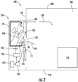
FIG. 2 depicts a transport refrigeration unit for a cargo compartment of the tractor trailer system ofFIG. 1 in an example embodiment having a leak detection system; -
FIG. 3 is a schematic illustration of a sensor assembly provided with the fluid delivery unit; -
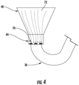
FIG. 4 is an illustration of a valve of the sensor assembly in a closed position; and -
FIG. 5 is an illustration of the valve of the sensor assembly in an open position. - A detailed description of one or more embodiments of the disclosed apparatus and method are presented herein by way of exemplification and not limitation with reference to the Figures.
- Referring to the Figures, a refrigerated trailer, a refrigerated space, or a refrigerated container may be provided with a refrigeration system that provides conditioned air or cooled air to an interior space of the refrigerated trailer, the refrigerated space, or the refrigerated container. The refrigerant may leak into the interior space and may present a hazard should the concentration of the leaked refrigerant within the interior space exceed a threshold level.
- Shown in
FIG. 1 is an embodiment of atractor trailer system 100. Thetractor trailer system 100 includes atractor 102 including an operator's compartment orcab 104 and also including an engine, which acts as the drive system of thetractor trailer system 100. Atrailer 106 is coupled to thetractor 102. Thetrailer 106 is a refrigeratedtrailer 106 and includes atop wall 108, a directly opposedbottom wall 110, opposedside walls 112, and afront wall 114, with thefront wall 114 being closest to thetractor 102. Thetrailer 106 further includes a door or doors (not shown) at arear wall 116, opposite thefront wall 114. The walls of thetrailer 106 define a cargo compartment. Thetrailer 106 is configured to maintain acargo 118 located inside the cargo compartment at a selected temperature through the use of atransport refrigeration unit 120 located on thetrailer 106. Thetransport refrigeration unit 120, as shown inFIG. 1 , is located at or attached to thefront wall 114. - Referring now to
FIG. 2 , thetransport refrigeration unit 120 is shown in more detail. Thetransport refrigeration unit 120 includes acompressor 122, acondenser 124, acondenser fan 125, anexpansion valve 126, anevaporator 128, and anevaporator fan 130, as well as other ancillary components. - Airflow is circulated into and through the cargo compartment of the
trailer 106 by means of thetransport refrigeration unit 120. Areturn airflow 134 flows into thetransport refrigeration unit 120 from the cargo compartment of thetrailer 106 through arefrigeration unit inlet 136, and across theevaporator 128 via theevaporator fan 130, thus cooling thereturn airflow 134. The cooledreturn airflow 134, now referred to assupply airflow 138, is supplied into the cargo compartment of thetrailer 106 through arefrigeration unit outlet 140, which in some embodiments is located near thetop wall 108 of thetrailer 106. Thesupply airflow 138 cools thecargo 118 in the cargo compartment of thetrailer 106. - A
leak detection system 10 is also located within thetransport refrigeration unit 120 and is arranged to detect the presence of refrigerant within thetransport refrigeration unit 120. Acontroller 12 may be provided and in communication with theleak detection system 10 and/or thetransportation refrigeration unit 120. Thecontroller 12 may control various system components and may be implemented using a general-purpose microprocessor executing a computer program stored on a storage medium to perform the operations described herein. - Although
FIG. 1 depicts a tractor-trailer arraignment, it is understood that embodiments described herein may be used with other cargo compartments, such as those in containers. Thus, embodiments are not limited to tractor-trailer systems. - As shown in
FIG. 2 , the refrigerant, e.g. the first fluid, within theevaporator 128 may leak into an interior space of thetrailer 106 or leak within thetransport refrigeration unit 120. The refrigerant may fall or descend below theevaporator 128 and be located proximate acollection area 20, should theevaporator fan 130 be off and not operating because the refrigerant may have a density that is greater than air. When thetransport refrigeration unit 120 is on and theevaporator fan 130 is operating, theevaporator fan 130 may duct or flow the refrigerant away from thecollection area 20 and towards therefrigeration unit outlet 140, potentially enabling the refrigerant to escape into thetrailer 106. - The
leak detection system 10 is arranged to detect the presence of refrigerant within thetransport refrigeration unit 120 before it escapes into thetrailer 106, regardless of whether theevaporator fan 130 is on or off. Therefore, theleak detection system 10 is arranged to detect the presence of refrigerant either within thecollection area 20 or in other areas, such as above theevaporator 128. The dual sensing locations facilitate a faster leak detection response time without having the refrigerant circulated throughout thetrailer 106. - As shown in
FIG. 3 theleak detection system 10 includes asensor assembly 30 that is at least partially disposed within thetransport refrigeration unit 120. Thesensor assembly 30 includes asensor housing 32, acollection housing 34, aconduit 36 that extends between thecollection housing 34 and thesensor housing 32 to fluidly connect thesensor housing 32 to thecollection housing 34, and thecontroller 12. Thesensor housing 32 and thecollection housing 34 are disposed on opposite sides of theevaporator 128 such that theevaporator 128 is disposed between thesensor housing 32 and thecollection housing 34. - Referring to
FIGS. 2 and3 , thesensor housing 32 is disposed within thecollection area 20. Thesensor housing 32 includes afirst fluid inlet 40, a receivingportion 42, and afirst valve 44. The first fluid inlet 40, thereceiving portion 42, and thefirst valve 44 may be integrated into thesensor housing 32 or all define thesensor housing 32. - The
first fluid inlet 40 extends between afirst end 50 and thesecond end 52. Thefirst end 50 may have a first cross-sectional form and thesecond end 52 may have a second cross-sectional form. The first cross-sectional form may be greater than the second cross-sectional form such that thefirst fluid inlet 40 has a funnel or frustoconical shape that directs a fluid flow from thefirst end 50 towards thesecond end 52 such that the fluid flow is directed towards thereceiving portion 42. - The
receiving portion 42 extends from thesecond end 52 of thefirst fluid inlet 40. Thereceiving portion 42 is arranged to receive aleak sensor 60. Thereceiving portion 42 may be integrally formed with theleak sensor 60 such that thereceiving portion 42 is a sensor housing of theleak sensor 60. Theleak sensor 60 is arranged to provide a signal indicative of a concentration or the presence of refrigerant within thetransport refrigeration unit 120 or that is received within thesensor housing 32 to thecontroller 12. Thereceiving portion 42 and theleak sensor 60 extends between thesecond end 52 of thefirst fluid inlet 40 and thefirst valve 44. - The
first valve 44 is disposed opposite thefirst fluid inlet 40 or spaced apart from thefirst fluid inlet 40 by the receivingportion 42. Thefirst valve 44 is movable between a closed position and an open position to selectively facilitate a fluid flow from thecollection housing 34 towards theleak sensor 60. Thefirst valve 44 inhibits a fluid flow from thecollection housing 34, through theconduit 36, towards theleak sensor 60 while in the closed position. Thefirst valve 44 facilitates a fluid flow from thecollection housing 34, through theconduit 36, to theleak sensor 60 while in the open position. - Referring to
FIGS. 3-5 , thefirst valve 44 includes avalve member 70 that moves between the closed position and the open position such that thefirst valve 44 selectively facilitates the fluid flow between thecollection housing 34 and thesensor housing 32. Thevalve member 70 is in a closed position while there is no fluid flow or fluid flow less than a threshold between thecollection housing 34 and thesensor housing 32 via theconduit 36, as shown inFIG. 4 . In at least one embodiment, afluid flow 72 in a first direction that is received through thefirst fluid inlet 40 of thesensor housing 32 may inhibit thevalve member 70 from moving away from the closed position. Thefluid flow 72 in the first direction may be the descending of the refrigerant into thefirst fluid inlet 40. Thevalve member 70 moves towards the open position while there is fluid flow greater than a threshold between thecollection housing 34 and thesensor housing 32 via theconduit 36, as shown inFIG. 5 . In at least one embodiment, afluid flow 74 in a second direction that is disposed opposite the first direction, that is received through thesecond fluid inlet 80 ofcollection housing 34 and directed through theconduit 36 towards thefirst valve 44, moves thevalve member 70 away from the closed position. Thefluid flow 74 in the second direction may be flow that flows through thecollection housing 34 through theconduit 36 due to the operation of theevaporator fan 130. - Referring to
FIGS. 2 and3 , thecollection housing 34 is spaced apart from thesensor housing 32. Thecollection housing 34 is disposed above theevaporator 128. Thecollection housing 34 includes asecond fluid inlet 80. Thesecond fluid inlet 80 extends between afirst end 82 and thesecond end 84. Thefirst end 82 may have a first cross-sectional form and thesecond end 84 may have a second cross-sectional form. The first cross-sectional form may be greater than the second cross-sectional form such that thesecond fluid inlet 80 has a general funnel or frustoconical shape that directs a fluid flow (e.g. the second fluid flow) from thefirst end 82 towards thesecond end 84 such that the fluid flow is directed towards theconduit 36 and towards theleak sensor 60. - The
conduit 36 extends between and is fluidly connected to thesensor housing 32 and thecollection housing 34. Theconduit 36 extends between thesecond end 84 of thesecond fluid inlet 80 of thecollection housing 34 and thefirst valve 44. - In at least one embodiment, the
first valve 44 may be connected to thesecond end 84 of thesecond fluid inlet 80 such that theconduit 36 extends between thefirst valve 44 and theleak sensor 60. - The
controller 12 may be a controller that is provided with the refrigeration system or may be a controller dedicated to theleak detection system 10. Thecontroller 12 is provided with input communication channels that are arranged to receive information, data, or signals from theleak sensor 60. Thecontroller 12 is provided with output communication channels that are arranged to provide commands, signals, or data to a display or a monitoring system. Thecontroller 12 is provided with at least one processor that is programmed to output for display an indicator based on information, data, or signals provided via the input communication channels and output commands via the output communication channels. - Responsive to operation of the
evaporator fan 130 moving the second fluid past theevaporator 128, a fluid flow enters thesecond fluid inlet 80 of thecollection housing 34 and flows through theconduit 36 towards thesensor housing 32. The fluid flow may move thevalve member 70 of thefirst valve 44 from the closed position towards the open position, enabling theleak sensor 60 to detect or monitor for the presence of the first fluid within the second fluid as shown inFigure 5 . Responsive to the descending of the refrigerant or first fluid from theevaporator 128, a fluid flow enters thefirst fluid inlet 40 of thesensor housing 32 and flows towards theleak sensor 60, enabling theleak sensor 60 to detect or monitor for the presence of the first fluid within the fluid flow from within thecollection area 20. - The
controller 12 is arranged to receive the signal from theleak sensor 60. Responsive to the signal being indicative of a concentration of the refrigerant (e.g. first fluid) within the fluid flow or within the second fluid being greater than a threshold concentration, thecontroller 12 is programmed to output for display an indicator. The indicator may be an auditory indicator, visual indicator, or the like that provides a notification as to the presence of a refrigerant leak. The indicator enables corrective action to be taken to mitigate the leak. In at least one embodiment, thecontroller 12 may be replaced with an indicator such as an indicator light that is arranged to receive a signal directly from theleak sensor 60. Responsive to the signal being indicative of a concentration of the refrigerant (e.g. first fluid) within the fluid flow or within the second fluid being greater than a threshold concentration, the indicator light is arranged to illuminate or output for display a luminous indicator. - The
leak detection system 10 enables two-sided detection within thetransport refrigeration unit 120 to enable faster leak detection times. Theleak detection system 10 facilitates the detection of refrigerant within thetransport refrigeration unit 120 regardless of if the fluid delivery unit is on and operational or off. - The term "about" is intended to include the degree of error associated with measurement of the particular quantity based upon the equipment available at the time of filing the application.
- The terminology used herein is for the purpose of describing particular embodiments only and is not intended to be limiting of the present disclosure. As used herein, the singular forms "a", "an" and "the" are intended to include the plural forms as well, unless the context clearly indicates otherwise. It will be further understood that the terms "comprises" and/or "comprising," when used in this specification, specify the presence of stated features, integers, steps, operations, elements, and/or components, but do not preclude the presence or addition of one or more other features, integers, steps, operations, element components, and/or groups thereof.
- While the present invention has been described with reference to an exemplary embodiment or embodiments, it will be understood by those skilled in the art that various changes may be made without departing from the scope of the present invention, which is defined by the claims. In addition, many modifications may be made to adapt a particular situation or material to the teachings of the present disclosure without departing from the present invention. Therefore, it is intended that the present invention not be limited to the particular embodiment disclosed as the best mode contemplated for carrying out this present invention, but that the present invention will include all embodiments falling within the scope of the claims.
Claims (6)
- A transport refrigeration unit (120), comprising:an evaporator (128) arranged to receive a refrigerant;an evaporator fan (130) spaced apart from the evaporator (128), the evaporator fan (130) being arranged to move air past the evaporator (128); anda leak detection system (10), comprising:
a sensor assembly (30) having:a sensor housing (32) defining a first fluid inlet (40),a leak sensor (60) disposed within the sensor housing (32), the leak sensor (60) being arranged to provide a signal indicative of a presence of the refrigerant within an interior space of the transport refrigeration unit (120),a collection housing (34), spaced apart from the sensor housing (32), the collection housing (34) defining a second fluid inlet (80), anda conduit (36) extending between and fluidly connected to the sensor (32) housing and the collection housing (34),characterized in that the sensor assembly comprises:
a first valve (44) disposed opposite the first fluid inlet (40), the first valve (44) being arranged to selectively facilitate a fluid flow between the collection housing (34) and the leak sensor (60). - The transport refrigeration unit (120) of claim 1, wherein the sensor assembly (30) further comprising:
a controller (12) arranged to receive the signal, the controller (12) being programmed to output for display an indicator, responsive to the signal being indicative of a concentration of the refrigerant within at least one of the interior space and within the air being greater than a threshold. - The transport refrigeration unit (120) of claim 1, wherein responsive to operation of the evaporator fan (130) moving the air past the evaporator (128), a fluid flow (74) enters the collection housing (34) and flows through the conduit (36) towards the sensor housing (32).
- The transport refrigeration unit (120) of claim 3, wherein the fluid flow (74) moves the first valve (44) from a closed position towards an open position.
- The transport refrigeration unit (120) of claim 1, wherein the evaporator (128) is disposed between the collection housing (34) and the sensor housing (32).
- A method of detecting a refrigerant leak within a transport refrigeration unit (120), comprising:receiving a fluid flow within at least one of a sensor housing (32) and a collection housing (34) that is spaced apart from the sensor housing (32) and fluidly connected to the sensor housing (32), wherein the sensor housing (32) is provided with a first valve (44) having a valve member (70) movable between an open position and a closed position;directing the fluid flow towards a leak sensor (60) disposed within the sensor housing (32); andoutputting for display an indicator, responsive to a concentration of a refrigerant present within the fluid flow being greater than a threshold concentration;characterized in that:responsive to the fluid flow (72) being received through a first fluid inlet (40) of the sensor housing (32), the valve member (70) is inhibited from moving away from the closed position; orresponsive to the fluid flow (74) being received through a second fluid inlet (80) of the collection housing (34) and directed towards the first valve (44),the valve member (70) is moved away from the closed position.
Applications Claiming Priority (2)
| Application Number | Priority Date | Filing Date | Title |
|---|---|---|---|
| US201862730183P | 2018-09-12 | 2018-09-12 | |
| PCT/US2019/049429 WO2020055633A1 (en) | 2018-09-12 | 2019-09-04 | Refrigerant leak detection system |
Publications (2)
| Publication Number | Publication Date |
|---|---|
| EP3850282A1 EP3850282A1 (en) | 2021-07-21 |
| EP3850282B1 true EP3850282B1 (en) | 2024-03-13 |
Family
ID=67982198
Family Applications (1)
| Application Number | Title | Priority Date | Filing Date |
|---|---|---|---|
| EP19769687.5A Active EP3850282B1 (en) | 2018-09-12 | 2019-09-04 | Refrigerant leak detection system |
Country Status (3)
| Country | Link |
|---|---|
| US (1) | US11472265B2 (en) |
| EP (1) | EP3850282B1 (en) |
| WO (1) | WO2020055633A1 (en) |
Families Citing this family (10)
| Publication number | Priority date | Publication date | Assignee | Title |
|---|---|---|---|---|
| US11231198B2 (en) | 2019-09-05 | 2022-01-25 | Trane International Inc. | Systems and methods for refrigerant leak detection in a climate control system |
| US11674726B2 (en) | 2020-06-30 | 2023-06-13 | Thermo King Llc | Systems and methods for transport climate control circuit management and isolation |
| US11614091B2 (en) | 2020-06-30 | 2023-03-28 | Thermo King Llc | Systems and methods for protecting sealed compressor electrical feedthrough |
| US11565575B2 (en) | 2020-06-30 | 2023-01-31 | Thermo King Llc | Air management system for climate control unit of a transport climate control system |
| US11554640B2 (en) | 2020-06-30 | 2023-01-17 | Thermo King Llc | Isolated evaporator coil for a transport climate control system |
| CN115839802A (en) * | 2021-09-09 | 2023-03-24 | 开利公司 | Sensor assembly and transport refrigeration device |
| US12253457B2 (en) | 2021-09-30 | 2025-03-18 | Carrier Corporation | Environmental enclosure for a transport gas sensor |
| USD1027682S1 (en) | 2021-09-30 | 2024-05-21 | Carrier Corporation | Refrigerant detection sensor housing |
| US12487008B2 (en) | 2022-01-14 | 2025-12-02 | Trane International Inc. | Method of commissioning an HVAC system |
| US12117191B2 (en) | 2022-06-24 | 2024-10-15 | Trane International Inc. | Climate control system with improved leak detector |
Family Cites Families (24)
| Publication number | Priority date | Publication date | Assignee | Title |
|---|---|---|---|---|
| JPS52145861A (en) | 1976-05-29 | 1977-12-05 | Kurimoto Ltd | Processer for scraps |
| SE500396C2 (en) * | 1992-10-16 | 1994-06-20 | Volvo Ab | Method and apparatus for diagnosing the amount of refrigerant in an air conditioning system |
| DE4426339C1 (en) | 1994-07-25 | 1995-08-24 | Daimler Benz Ag | Vehicle air-conditioning system |
| WO2002027245A1 (en) | 2000-09-26 | 2002-04-04 | Daikin Industries, Ltd. | Air conditioner |
| US6742384B2 (en) * | 2002-07-02 | 2004-06-01 | Carrier Corporation | Trace gas management system for leak detection operations |
| JP2004353895A (en) | 2003-05-27 | 2004-12-16 | Sanden Corp | Vehicular air-conditioner |
| DE10337753A1 (en) | 2003-08-08 | 2005-03-03 | Robert Bosch Gmbh | Air conditioning, in particular for use in motor vehicles and methods for their operation |
| DE102006006963A1 (en) | 2006-02-14 | 2007-08-23 | Bayerische Motoren Werke Ag | Air conditioning system for vehicle, comprises sensor unit for detection of carbon dioxide leak |
| WO2009091399A1 (en) | 2008-01-17 | 2009-07-23 | Carrier Corporation | Detection of co2 leakage in a container |
| JP5642648B2 (en) | 2011-09-29 | 2014-12-17 | ホシザキ電機株式会社 | Ice machine |
| JP5916360B2 (en) | 2011-11-30 | 2016-05-11 | 三菱重工業株式会社 | Turbo refrigerator |
| AU2013101100B4 (en) | 2013-08-17 | 2013-11-07 | Pioneer International Pty Ltd | An Arrangement and Method For Retrofitting an Air Conditioning System |
| WO2015029094A1 (en) | 2013-08-25 | 2015-03-05 | Masuda Keiji | Leak detecting structure for flammable refrigerant |
| JP2015094513A (en) | 2013-11-12 | 2015-05-18 | ダイキン工業株式会社 | Air conditioner |
| WO2016079801A1 (en) * | 2014-11-18 | 2016-05-26 | 三菱電機株式会社 | Air conditioning device |
| JP6137263B2 (en) | 2015-09-30 | 2017-05-31 | ダイキン工業株式会社 | Refrigeration system for storage |
| JP6137264B2 (en) | 2015-09-30 | 2017-05-31 | ダイキン工業株式会社 | Refrigeration equipment |
| EP3374705B1 (en) | 2015-11-09 | 2023-12-27 | Carrier Corporation | Parallel loop intermodal container |
| WO2017083336A1 (en) | 2015-11-09 | 2017-05-18 | Carrier Corporation | Refrigerated transport system with refrigerant dilution |
| EP3394528B1 (en) | 2015-12-22 | 2023-08-09 | Carrier Corporation | Safety system for a container having a refrigeration system and method of providing safety |
| DE102016209931A1 (en) * | 2016-06-06 | 2017-12-07 | Mahle International Gmbh | Arrangement for collecting and removing leaked refrigerant |
| CN110226073B (en) | 2017-02-09 | 2021-05-18 | 大金工业株式会社 | refrigeration unit |
| US11268472B2 (en) | 2017-02-24 | 2022-03-08 | Carrier Corporation | Methane safety systems for transport refrigeration units |
| US11407287B2 (en) * | 2019-04-11 | 2022-08-09 | Carrier Corporation | Refrigerant leak sensor pre-trip sequence and diagnostics |
-
2019
- 2019-09-04 WO PCT/US2019/049429 patent/WO2020055633A1/en not_active Ceased
- 2019-09-04 US US16/972,131 patent/US11472265B2/en active Active
- 2019-09-04 EP EP19769687.5A patent/EP3850282B1/en active Active
Also Published As
| Publication number | Publication date |
|---|---|
| EP3850282A1 (en) | 2021-07-21 |
| US11472265B2 (en) | 2022-10-18 |
| US20210229528A1 (en) | 2021-07-29 |
| WO2020055633A1 (en) | 2020-03-19 |
Similar Documents
| Publication | Publication Date | Title |
|---|---|---|
| EP3850282B1 (en) | Refrigerant leak detection system | |
| EP3833914B1 (en) | Heated gas detector for a transportation refrigeration unit | |
| EP3847401B1 (en) | Refrigerant leak detection system | |
| EP4025848B1 (en) | Refrigerant system operation sequences for leak prevention | |
| EP3811008B1 (en) | Refrigerated container provided with ventilation system | |
| US20040146085A1 (en) | Temperature control using infrared sensing | |
| US12233687B2 (en) | Transport climate control remote management | |
| US20230314055A1 (en) | Systems and methods for transport climate control circuit management and isolation | |
| EP3586073B1 (en) | Methane-powered refrigeration unit | |
| WO2017147299A1 (en) | Active system for improved temperature control and air mixing inside refrigerated truck boxes, trailers and intermodal containers | |
| EP3990845B1 (en) | Transportation refrigeration unit with adaptive defrost | |
| EP3390931B1 (en) | Methods and systems for checking proper airflow within a container | |
| EP3384213B1 (en) | Economized device control for refrigeration systems | |
| US12498155B2 (en) | Transportation refrigeration unit and method of measuring quantity of refrigerant in the same | |
| EP4311724A1 (en) | Transport refrigeration system |
Legal Events
| Date | Code | Title | Description |
|---|---|---|---|
| STAA | Information on the status of an ep patent application or granted ep patent |
Free format text: STATUS: UNKNOWN |
|
| STAA | Information on the status of an ep patent application or granted ep patent |
Free format text: STATUS: THE INTERNATIONAL PUBLICATION HAS BEEN MADE |
|
| PUAI | Public reference made under article 153(3) epc to a published international application that has entered the european phase |
Free format text: ORIGINAL CODE: 0009012 |
|
| STAA | Information on the status of an ep patent application or granted ep patent |
Free format text: STATUS: REQUEST FOR EXAMINATION WAS MADE |
|
| 17P | Request for examination filed |
Effective date: 20210111 |
|
| AK | Designated contracting states |
Kind code of ref document: A1 Designated state(s): AL AT BE BG CH CY CZ DE DK EE ES FI FR GB GR HR HU IE IS IT LI LT LU LV MC MK MT NL NO PL PT RO RS SE SI SK SM TR |
|
| DAV | Request for validation of the european patent (deleted) | ||
| DAX | Request for extension of the european patent (deleted) | ||
| GRAP | Despatch of communication of intention to grant a patent |
Free format text: ORIGINAL CODE: EPIDOSNIGR1 |
|
| STAA | Information on the status of an ep patent application or granted ep patent |
Free format text: STATUS: GRANT OF PATENT IS INTENDED |
|
| INTG | Intention to grant announced |
Effective date: 20230925 |
|
| GRAS | Grant fee paid |
Free format text: ORIGINAL CODE: EPIDOSNIGR3 |
|
| GRAA | (expected) grant |
Free format text: ORIGINAL CODE: 0009210 |
|
| STAA | Information on the status of an ep patent application or granted ep patent |
Free format text: STATUS: THE PATENT HAS BEEN GRANTED |
|
| AK | Designated contracting states |
Kind code of ref document: B1 Designated state(s): AL AT BE BG CH CY CZ DE DK EE ES FI FR GB GR HR HU IE IS IT LI LT LU LV MC MK MT NL NO PL PT RO RS SE SI SK SM TR |
|
| REG | Reference to a national code |
Ref country code: GB Ref legal event code: FG4D |
|
| REG | Reference to a national code |
Ref country code: CH Ref legal event code: EP |
|
| REG | Reference to a national code |
Ref country code: DE Ref legal event code: R096 Ref document number: 602019048245 Country of ref document: DE |
|
| REG | Reference to a national code |
Ref country code: IE Ref legal event code: FG4D |
|
| PG25 | Lapsed in a contracting state [announced via postgrant information from national office to epo] |
Ref country code: LT Free format text: LAPSE BECAUSE OF FAILURE TO SUBMIT A TRANSLATION OF THE DESCRIPTION OR TO PAY THE FEE WITHIN THE PRESCRIBED TIME-LIMIT Effective date: 20240313 |
|
| REG | Reference to a national code |
Ref country code: LT Ref legal event code: MG9D |
|
| PG25 | Lapsed in a contracting state [announced via postgrant information from national office to epo] |
Ref country code: GR Free format text: LAPSE BECAUSE OF FAILURE TO SUBMIT A TRANSLATION OF THE DESCRIPTION OR TO PAY THE FEE WITHIN THE PRESCRIBED TIME-LIMIT Effective date: 20240614 |
|
| REG | Reference to a national code |
Ref country code: NL Ref legal event code: MP Effective date: 20240313 |
|
| PG25 | Lapsed in a contracting state [announced via postgrant information from national office to epo] |
Ref country code: RS Free format text: LAPSE BECAUSE OF FAILURE TO SUBMIT A TRANSLATION OF THE DESCRIPTION OR TO PAY THE FEE WITHIN THE PRESCRIBED TIME-LIMIT Effective date: 20240613 Ref country code: HR Free format text: LAPSE BECAUSE OF FAILURE TO SUBMIT A TRANSLATION OF THE DESCRIPTION OR TO PAY THE FEE WITHIN THE PRESCRIBED TIME-LIMIT Effective date: 20240313 |
|
| PG25 | Lapsed in a contracting state [announced via postgrant information from national office to epo] |
Ref country code: ES Free format text: LAPSE BECAUSE OF FAILURE TO SUBMIT A TRANSLATION OF THE DESCRIPTION OR TO PAY THE FEE WITHIN THE PRESCRIBED TIME-LIMIT Effective date: 20240313 |
|
| PG25 | Lapsed in a contracting state [announced via postgrant information from national office to epo] |
Ref country code: RS Free format text: LAPSE BECAUSE OF FAILURE TO SUBMIT A TRANSLATION OF THE DESCRIPTION OR TO PAY THE FEE WITHIN THE PRESCRIBED TIME-LIMIT Effective date: 20240613 Ref country code: NO Free format text: LAPSE BECAUSE OF FAILURE TO SUBMIT A TRANSLATION OF THE DESCRIPTION OR TO PAY THE FEE WITHIN THE PRESCRIBED TIME-LIMIT Effective date: 20240613 Ref country code: LT Free format text: LAPSE BECAUSE OF FAILURE TO SUBMIT A TRANSLATION OF THE DESCRIPTION OR TO PAY THE FEE WITHIN THE PRESCRIBED TIME-LIMIT Effective date: 20240313 Ref country code: HR Free format text: LAPSE BECAUSE OF FAILURE TO SUBMIT A TRANSLATION OF THE DESCRIPTION OR TO PAY THE FEE WITHIN THE PRESCRIBED TIME-LIMIT Effective date: 20240313 Ref country code: GR Free format text: LAPSE BECAUSE OF FAILURE TO SUBMIT A TRANSLATION OF THE DESCRIPTION OR TO PAY THE FEE WITHIN THE PRESCRIBED TIME-LIMIT Effective date: 20240614 Ref country code: FI Free format text: LAPSE BECAUSE OF FAILURE TO SUBMIT A TRANSLATION OF THE DESCRIPTION OR TO PAY THE FEE WITHIN THE PRESCRIBED TIME-LIMIT Effective date: 20240313 Ref country code: ES Free format text: LAPSE BECAUSE OF FAILURE TO SUBMIT A TRANSLATION OF THE DESCRIPTION OR TO PAY THE FEE WITHIN THE PRESCRIBED TIME-LIMIT Effective date: 20240313 Ref country code: BG Free format text: LAPSE BECAUSE OF FAILURE TO SUBMIT A TRANSLATION OF THE DESCRIPTION OR TO PAY THE FEE WITHIN THE PRESCRIBED TIME-LIMIT Effective date: 20240313 |
|
| REG | Reference to a national code |
Ref country code: AT Ref legal event code: MK05 Ref document number: 1666102 Country of ref document: AT Kind code of ref document: T Effective date: 20240313 |
|
| PG25 | Lapsed in a contracting state [announced via postgrant information from national office to epo] |
Ref country code: SE Free format text: LAPSE BECAUSE OF FAILURE TO SUBMIT A TRANSLATION OF THE DESCRIPTION OR TO PAY THE FEE WITHIN THE PRESCRIBED TIME-LIMIT Effective date: 20240313 Ref country code: LV Free format text: LAPSE BECAUSE OF FAILURE TO SUBMIT A TRANSLATION OF THE DESCRIPTION OR TO PAY THE FEE WITHIN THE PRESCRIBED TIME-LIMIT Effective date: 20240313 |
|
| PG25 | Lapsed in a contracting state [announced via postgrant information from national office to epo] |
Ref country code: NL Free format text: LAPSE BECAUSE OF FAILURE TO SUBMIT A TRANSLATION OF THE DESCRIPTION OR TO PAY THE FEE WITHIN THE PRESCRIBED TIME-LIMIT Effective date: 20240313 |
|
| PG25 | Lapsed in a contracting state [announced via postgrant information from national office to epo] |
Ref country code: NL Free format text: LAPSE BECAUSE OF FAILURE TO SUBMIT A TRANSLATION OF THE DESCRIPTION OR TO PAY THE FEE WITHIN THE PRESCRIBED TIME-LIMIT Effective date: 20240313 |
|
| PG25 | Lapsed in a contracting state [announced via postgrant information from national office to epo] |
Ref country code: IS Free format text: LAPSE BECAUSE OF FAILURE TO SUBMIT A TRANSLATION OF THE DESCRIPTION OR TO PAY THE FEE WITHIN THE PRESCRIBED TIME-LIMIT Effective date: 20240713 |
|
| PG25 | Lapsed in a contracting state [announced via postgrant information from national office to epo] |
Ref country code: PT Free format text: LAPSE BECAUSE OF FAILURE TO SUBMIT A TRANSLATION OF THE DESCRIPTION OR TO PAY THE FEE WITHIN THE PRESCRIBED TIME-LIMIT Effective date: 20240715 Ref country code: SM Free format text: LAPSE BECAUSE OF FAILURE TO SUBMIT A TRANSLATION OF THE DESCRIPTION OR TO PAY THE FEE WITHIN THE PRESCRIBED TIME-LIMIT Effective date: 20240313 |
|
| PG25 | Lapsed in a contracting state [announced via postgrant information from national office to epo] |
Ref country code: EE Free format text: LAPSE BECAUSE OF FAILURE TO SUBMIT A TRANSLATION OF THE DESCRIPTION OR TO PAY THE FEE WITHIN THE PRESCRIBED TIME-LIMIT Effective date: 20240313 Ref country code: CZ Free format text: LAPSE BECAUSE OF FAILURE TO SUBMIT A TRANSLATION OF THE DESCRIPTION OR TO PAY THE FEE WITHIN THE PRESCRIBED TIME-LIMIT Effective date: 20240313 |
|
| PG25 | Lapsed in a contracting state [announced via postgrant information from national office to epo] |
Ref country code: AT Free format text: LAPSE BECAUSE OF FAILURE TO SUBMIT A TRANSLATION OF THE DESCRIPTION OR TO PAY THE FEE WITHIN THE PRESCRIBED TIME-LIMIT Effective date: 20240313 |
|
| PG25 | Lapsed in a contracting state [announced via postgrant information from national office to epo] |
Ref country code: PL Free format text: LAPSE BECAUSE OF FAILURE TO SUBMIT A TRANSLATION OF THE DESCRIPTION OR TO PAY THE FEE WITHIN THE PRESCRIBED TIME-LIMIT Effective date: 20240313 |
|
| PG25 | Lapsed in a contracting state [announced via postgrant information from national office to epo] |
Ref country code: SK Free format text: LAPSE BECAUSE OF FAILURE TO SUBMIT A TRANSLATION OF THE DESCRIPTION OR TO PAY THE FEE WITHIN THE PRESCRIBED TIME-LIMIT Effective date: 20240313 |
|
| PG25 | Lapsed in a contracting state [announced via postgrant information from national office to epo] |
Ref country code: SM Free format text: LAPSE BECAUSE OF FAILURE TO SUBMIT A TRANSLATION OF THE DESCRIPTION OR TO PAY THE FEE WITHIN THE PRESCRIBED TIME-LIMIT Effective date: 20240313 Ref country code: SK Free format text: LAPSE BECAUSE OF FAILURE TO SUBMIT A TRANSLATION OF THE DESCRIPTION OR TO PAY THE FEE WITHIN THE PRESCRIBED TIME-LIMIT Effective date: 20240313 Ref country code: RO Free format text: LAPSE BECAUSE OF FAILURE TO SUBMIT A TRANSLATION OF THE DESCRIPTION OR TO PAY THE FEE WITHIN THE PRESCRIBED TIME-LIMIT Effective date: 20240313 Ref country code: PT Free format text: LAPSE BECAUSE OF FAILURE TO SUBMIT A TRANSLATION OF THE DESCRIPTION OR TO PAY THE FEE WITHIN THE PRESCRIBED TIME-LIMIT Effective date: 20240715 Ref country code: PL Free format text: LAPSE BECAUSE OF FAILURE TO SUBMIT A TRANSLATION OF THE DESCRIPTION OR TO PAY THE FEE WITHIN THE PRESCRIBED TIME-LIMIT Effective date: 20240313 Ref country code: IS Free format text: LAPSE BECAUSE OF FAILURE TO SUBMIT A TRANSLATION OF THE DESCRIPTION OR TO PAY THE FEE WITHIN THE PRESCRIBED TIME-LIMIT Effective date: 20240713 Ref country code: EE Free format text: LAPSE BECAUSE OF FAILURE TO SUBMIT A TRANSLATION OF THE DESCRIPTION OR TO PAY THE FEE WITHIN THE PRESCRIBED TIME-LIMIT Effective date: 20240313 Ref country code: CZ Free format text: LAPSE BECAUSE OF FAILURE TO SUBMIT A TRANSLATION OF THE DESCRIPTION OR TO PAY THE FEE WITHIN THE PRESCRIBED TIME-LIMIT Effective date: 20240313 Ref country code: AT Free format text: LAPSE BECAUSE OF FAILURE TO SUBMIT A TRANSLATION OF THE DESCRIPTION OR TO PAY THE FEE WITHIN THE PRESCRIBED TIME-LIMIT Effective date: 20240313 |
|
| PG25 | Lapsed in a contracting state [announced via postgrant information from national office to epo] |
Ref country code: IT Free format text: LAPSE BECAUSE OF FAILURE TO SUBMIT A TRANSLATION OF THE DESCRIPTION OR TO PAY THE FEE WITHIN THE PRESCRIBED TIME-LIMIT Effective date: 20240313 |
|
| REG | Reference to a national code |
Ref country code: DE Ref legal event code: R097 Ref document number: 602019048245 Country of ref document: DE |
|
| PG25 | Lapsed in a contracting state [announced via postgrant information from national office to epo] |
Ref country code: IT Free format text: LAPSE BECAUSE OF FAILURE TO SUBMIT A TRANSLATION OF THE DESCRIPTION OR TO PAY THE FEE WITHIN THE PRESCRIBED TIME-LIMIT Effective date: 20240313 |
|
| PG25 | Lapsed in a contracting state [announced via postgrant information from national office to epo] |
Ref country code: DK Free format text: LAPSE BECAUSE OF FAILURE TO SUBMIT A TRANSLATION OF THE DESCRIPTION OR TO PAY THE FEE WITHIN THE PRESCRIBED TIME-LIMIT Effective date: 20240313 |
|
| PLBE | No opposition filed within time limit |
Free format text: ORIGINAL CODE: 0009261 |
|
| STAA | Information on the status of an ep patent application or granted ep patent |
Free format text: STATUS: NO OPPOSITION FILED WITHIN TIME LIMIT |
|
| PG25 | Lapsed in a contracting state [announced via postgrant information from national office to epo] |
Ref country code: DK Free format text: LAPSE BECAUSE OF FAILURE TO SUBMIT A TRANSLATION OF THE DESCRIPTION OR TO PAY THE FEE WITHIN THE PRESCRIBED TIME-LIMIT Effective date: 20240313 |
|
| 26N | No opposition filed |
Effective date: 20241216 |
|
| PG25 | Lapsed in a contracting state [announced via postgrant information from national office to epo] |
Ref country code: SI Free format text: LAPSE BECAUSE OF FAILURE TO SUBMIT A TRANSLATION OF THE DESCRIPTION OR TO PAY THE FEE WITHIN THE PRESCRIBED TIME-LIMIT Effective date: 20240313 Ref country code: MC Free format text: LAPSE BECAUSE OF FAILURE TO SUBMIT A TRANSLATION OF THE DESCRIPTION OR TO PAY THE FEE WITHIN THE PRESCRIBED TIME-LIMIT Effective date: 20240313 |
|
| REG | Reference to a national code |
Ref country code: CH Ref legal event code: PL |
|
| PG25 | Lapsed in a contracting state [announced via postgrant information from national office to epo] |
Ref country code: LU Free format text: LAPSE BECAUSE OF NON-PAYMENT OF DUE FEES Effective date: 20240904 |
|
| REG | Reference to a national code |
Ref country code: BE Ref legal event code: MM Effective date: 20240930 |
|
| PG25 | Lapsed in a contracting state [announced via postgrant information from national office to epo] |
Ref country code: BE Free format text: LAPSE BECAUSE OF NON-PAYMENT OF DUE FEES Effective date: 20240930 |
|
| PG25 | Lapsed in a contracting state [announced via postgrant information from national office to epo] |
Ref country code: CH Free format text: LAPSE BECAUSE OF NON-PAYMENT OF DUE FEES Effective date: 20240930 |
|
| PG25 | Lapsed in a contracting state [announced via postgrant information from national office to epo] |
Ref country code: IE Free format text: LAPSE BECAUSE OF NON-PAYMENT OF DUE FEES Effective date: 20240904 |
|
| PGFP | Annual fee paid to national office [announced via postgrant information from national office to epo] |
Ref country code: DE Payment date: 20250820 Year of fee payment: 7 |
|
| PGFP | Annual fee paid to national office [announced via postgrant information from national office to epo] |
Ref country code: GB Payment date: 20250822 Year of fee payment: 7 |
|
| PGFP | Annual fee paid to national office [announced via postgrant information from national office to epo] |
Ref country code: FR Payment date: 20250820 Year of fee payment: 7 |
|
| PG25 | Lapsed in a contracting state [announced via postgrant information from national office to epo] |
Ref country code: CY Free format text: LAPSE BECAUSE OF FAILURE TO SUBMIT A TRANSLATION OF THE DESCRIPTION OR TO PAY THE FEE WITHIN THE PRESCRIBED TIME-LIMIT; INVALID AB INITIO Effective date: 20190904 |
|
| PG25 | Lapsed in a contracting state [announced via postgrant information from national office to epo] |
Ref country code: HU Free format text: LAPSE BECAUSE OF FAILURE TO SUBMIT A TRANSLATION OF THE DESCRIPTION OR TO PAY THE FEE WITHIN THE PRESCRIBED TIME-LIMIT; INVALID AB INITIO Effective date: 20190904 |