EP3850274B1 - Cooking appliance having cooling system - Google Patents
Cooking appliance having cooling system Download PDFInfo
- Publication number
- EP3850274B1 EP3850274B1 EP19897508.8A EP19897508A EP3850274B1 EP 3850274 B1 EP3850274 B1 EP 3850274B1 EP 19897508 A EP19897508 A EP 19897508A EP 3850274 B1 EP3850274 B1 EP 3850274B1
- Authority
- EP
- European Patent Office
- Prior art keywords
- cooling duct
- duct
- cooktop
- cooking appliance
- electrical component
- Prior art date
- Legal status (The legal status is an assumption and is not a legal conclusion. Google has not performed a legal analysis and makes no representation as to the accuracy of the status listed.)
- Active
Links
Images







Classifications
-
- F—MECHANICAL ENGINEERING; LIGHTING; HEATING; WEAPONS; BLASTING
- F24—HEATING; RANGES; VENTILATING
- F24C—DOMESTIC STOVES OR RANGES ; DETAILS OF DOMESTIC STOVES OR RANGES, OF GENERAL APPLICATION
- F24C15/00—Details
- F24C15/006—Arrangements for circulation of cooling air
-
- F—MECHANICAL ENGINEERING; LIGHTING; HEATING; WEAPONS; BLASTING
- F24—HEATING; RANGES; VENTILATING
- F24C—DOMESTIC STOVES OR RANGES ; DETAILS OF DOMESTIC STOVES OR RANGES, OF GENERAL APPLICATION
- F24C15/00—Details
- F24C15/02—Doors specially adapted for stoves or ranges
-
- F—MECHANICAL ENGINEERING; LIGHTING; HEATING; WEAPONS; BLASTING
- F24—HEATING; RANGES; VENTILATING
- F24C—DOMESTIC STOVES OR RANGES ; DETAILS OF DOMESTIC STOVES OR RANGES, OF GENERAL APPLICATION
- F24C15/00—Details
- F24C15/02—Doors specially adapted for stoves or ranges
- F24C15/025—Doors specially adapted for stoves or ranges with air curtain closures
-
- F—MECHANICAL ENGINEERING; LIGHTING; HEATING; WEAPONS; BLASTING
- F24—HEATING; RANGES; VENTILATING
- F24C—DOMESTIC STOVES OR RANGES ; DETAILS OF DOMESTIC STOVES OR RANGES, OF GENERAL APPLICATION
- F24C15/00—Details
- F24C15/08—Foundations or supports plates; Legs or pillars; Casings; Wheels
-
- F—MECHANICAL ENGINEERING; LIGHTING; HEATING; WEAPONS; BLASTING
- F24—HEATING; RANGES; VENTILATING
- F24C—DOMESTIC STOVES OR RANGES ; DETAILS OF DOMESTIC STOVES OR RANGES, OF GENERAL APPLICATION
- F24C15/00—Details
- F24C15/10—Tops, e.g. hot plates; Rings
- F24C15/101—Tops, e.g. hot plates; Rings provisions for circulation of air
-
- F—MECHANICAL ENGINEERING; LIGHTING; HEATING; WEAPONS; BLASTING
- F24—HEATING; RANGES; VENTILATING
- F24C—DOMESTIC STOVES OR RANGES ; DETAILS OF DOMESTIC STOVES OR RANGES, OF GENERAL APPLICATION
- F24C15/00—Details
- F24C15/10—Tops, e.g. hot plates; Rings
- F24C15/102—Tops, e.g. hot plates; Rings electrically heated
-
- F—MECHANICAL ENGINEERING; LIGHTING; HEATING; WEAPONS; BLASTING
- F24—HEATING; RANGES; VENTILATING
- F24C—DOMESTIC STOVES OR RANGES ; DETAILS OF DOMESTIC STOVES OR RANGES, OF GENERAL APPLICATION
- F24C15/00—Details
- F24C15/32—Arrangements of ducts for hot gases, e.g. in or around baking ovens
- F24C15/322—Arrangements of ducts for hot gases, e.g. in or around baking ovens with forced circulation
-
- F—MECHANICAL ENGINEERING; LIGHTING; HEATING; WEAPONS; BLASTING
- F24—HEATING; RANGES; VENTILATING
- F24C—DOMESTIC STOVES OR RANGES ; DETAILS OF DOMESTIC STOVES OR RANGES, OF GENERAL APPLICATION
- F24C3/00—Stoves or ranges for gaseous fuels
- F24C3/12—Arrangement or mounting of control or safety devices
- F24C3/126—Arrangement or mounting of control or safety devices on ranges
-
- F—MECHANICAL ENGINEERING; LIGHTING; HEATING; WEAPONS; BLASTING
- F24—HEATING; RANGES; VENTILATING
- F24C—DOMESTIC STOVES OR RANGES ; DETAILS OF DOMESTIC STOVES OR RANGES, OF GENERAL APPLICATION
- F24C7/00—Stoves or ranges heated by electric energy
- F24C7/08—Arrangement or mounting of control or safety devices
- F24C7/082—Arrangement or mounting of control or safety devices on ranges, e.g. control panels, illumination
Definitions
- the disclosure relates to a cooking appliance such as an oven range, and more particularly to a cooking appliance having a cooling system.
- An oven range having an oven provided in the lower side thereof and a cooktop provided in the upper side thereof is widely used as a cooking appliance.
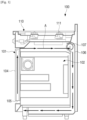
- Such an oven range is equipped with a cooling system as illustrated in FIG. 1 in order to prevent the outside surface of the oven from being overheated by the heat generated when the oven is operated.
- a conventional oven range 100 is provided with a cooling passage 106 for cooling the outer surface of the oven 101 around the cooking chamber 102 of the oven 101.
- the cooling passage 106 is provided along the inside of the door 104 and the top, rear, and bottom surfaces of the cooking chamber 102 of the oven 101.
- a cooktop 110 is provided above the cooling passage 106 provided on the top surface of the oven 101.
- the cooling passage 106 is provided with a fan motor 107 capable of sucking outside cold air into the cooling passage 106.
- outside cold air (arrow A) is sucked into the cooling passage 106 through a suction port 105 provided at the lower end of the door 104, passes through the inside of the door 104 and the top, rear, and bottom surfaces of the cooking chamber 102, and then is discharged to the outside of the conventional oven range 100.
- the outside surface of the oven 101 is cooled by the outside cold air traveling along the cooling passage 106 provided on the outer surface of the cooking chamber 102.
- the cooktop 110 provided in the upper side is not provided with the cooling system. Therefore, when cooking by operating the cooktop 110, the temperature of the inside of the cooktop 110 is increased by the radiant heat of a burner 111.
- FR 2726633 A1 relates to a cooking apparatus for cooling the door of a cooking appliance and a cooking appliance implementing the method.
- US 3889100 A relates to baking and broiling ovens, and particularly to a forced air cooling system for maintaining the outer surfaces of the oven below predetermined maximum temperatures.
- An aspect of the present disclosure relates a cooking appliance having a cooling system that can cool the outside of the oven and electrical components disposed inside the cooktop.
- a cooking appliance is provided according to claim 1..
- the bottom surface of the cooktop is spaced apart from the first cooling duct, and a connection duct is provided between the second cooling duct and the first cooling duct to connect the first cooling duct and the second cooling duct perpendicular to the bottom surface of the cooktop.
- the cooking appliance having a cooling system may include a second electrical component disposed on the bottom surface of the cooktop, wherein the second cooling duct may be connected to the first cooling duct between the second electrical component and the exhaust duct.
- the first electrical component may be disposed at a center of an inner surface of the front surface of the cooktop, and the bottom surface of the cooktop may be provided with a receiving portion in which the second electrical component is disposed and an outlet through which air is discharged.
- the second cooling duct may be formed of the front surface, the rear surface, a top surface, the bottom surface, and both side surfaces of the cooktop, and the bottom surface of the cooktop is provided with an outlet through which the outside air sucked into the second suction port is discharged.
- a top surface of the first cooling duct is provided with a communication port communicating with the connection duct.
- the first cooling duct may include a first duct section that is gradually narrower in width than the first suction port and a second duct section that is connected to the first duct section, is gradually higher in height than the first duct section, and is connected to the exhaust fan, and the second cooling duct may be connected to the second duct section.
- the cooking appliance having a cooling system may include a door provided to open and close the cooking chamber in the front surface of the oven; and a door air passage provided inside the door to communicate with the first cooling duct, wherein a lower end of the door air passage may be opened to an outside.
- outside air is sucked into the first suction port of the first cooling duct, the second suction port of the second cooling duct, and the lower end of the door air passage.
- the outside air sucked into the first suction port may cool the top surface of the oven while passing through the first cooling duct and is discharged to the outside through the exhaust duct
- the outside air sucked into the second suction port may cool the first electrical component, is introduced into the first cooling duct, and is discharged to the outside through the exhaust duct
- the outside air sucked into the lower end of the door air passage may cool the door, is introduced into the first cooling duct, and then is discharged to the outside through the exhaust duct.
- a cooking appliance having a cooling system may include an oven having a cooking chamber therein; a cooktop provided at an upper side of the oven; a first electrical component disposed in a front surface of the cooktop; a second electrical component disposed on a bottom surface of the cooktop; a first cooling duct provided between a top surface of the oven and the bottom surface of the cooktop and configured to communicate with a first suction port formed in a front surface of the oven; an exhaust duct disposed in a rear surface of the cooktop and connected to a rear end of the first cooling duct; a second cooling duct configured to communicate with a second suction port formed in the front surface of the cooktop above the first electrical component, the second cooling duct provided inside the cooktop; and an exhaust fan disposed in a connecting section between the first cooling duct and the exhaust duct, wherein the second cooling duct may be connected to the first cooling duct between the second electrical component and the exhaust duct.
- the cooking appliance having a cooling system according to an embodiment of the present disclosure having the structure as described above may cool the inside of the cooktop through a cooling duct provided in the cooktop, so that electrical components may be disposed inside the cooktop.
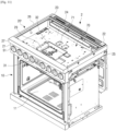
- FIG 2 is a perspective view illustrating a cooking appliance having a cooling system according to the invention.
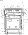
- FIG 3 is a cross-sectional view illustrating a cooking appliance having a cooling system according to the invention.
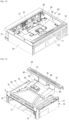
- FIG 4 is a perspective view illustrating an inside of a cooktop of the cooking appliance having a cooling system FIG 2
- FIG 5 is a rear perspective view illustrating an inside of a cooktop of the cooking appliance having a cooling system FIG 2
- FIG 6 is a partial perspective view illustrating a second suction port of a second cooling duct of the cooking appliance having a cooling system of FIG 2
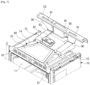
- FIG 7 is a perspective view illustrating a first cooling duct and an exhaust duct of the cooking appliance having a cooling system of FIG 2
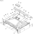
- FIG 8 is an exploded perspective view illustrating a state in which a connection duct is separated from the first cooling duct of FIG 7 .
- a cooking appliance 1 having a cooling system includes an oven 10, a cooktop 20, an electrical component 30, and a cooling system 40.
- the oven 10 is formed in a substantially rectangular parallelepiped shape, and a cooking chamber 11 in which food is accommodated is proved in the oven 10.
- a heating source (not illustrated) configured to heat food is provided in the cooking chamber 11.
- a gas burner, an electric heater, or the like may be used as the heating source.
- the internal structure of the oven 10 is the same or similar to a gas oven, an electric oven, and the like according to the prior art; therefore, a detailed description thereof is omitted.
- a door 12 configured to open and close the cooking chamber 11 is provided in the front surface of the oven 10.
- the door 12 may be disposed to be rotated approximately 90 degrees by hinges provided at the lower portion thereof.
- a door air passage 13 through which outside air passes is provided inside the door 12. Openings 12a and 12b are provided at the upper and lower ends, respectively, of the door 12 to allow air to be introduced into the door air passage 13. Therefore, the lower end of the door air passage 13 is opened to the outside of the oven 10.
- the cooktop 20 is provided at the upper side of the oven 10 and is formed in a hollow substantially rectangular parallelepiped shape.
- the cooktop 20 may include a front surface 21, a rear surface 22, a top surface 23, a bottom surface 24, and both side surfaces 25 and 26.
- FIGS. 3 and 4 illustrate the cooktop 20, the top surface 23 of which is removed to show the inside of the cooktop 20.
- the top surface 23 of the cooktop 20 is provided with a plurality of heating sources 50 capable of heating a container containing food.
- a plurality of heating sources 50 capable of heating a container containing food.
- six gas burners are used as the heating sources 50.
- the heating source 50 of the cooktop 20 is not limited to the gas burner.
- an electromagnetic induction heater, an electric heater, or the like may be used as the heating source 50.
- an induction cooktop, a highlight cooktop, and a hybrid cooktop may be used as the cooktop 20.
- the front surface 21 of the cooktop 20 is provided with a plurality of rotary switches 51 that can control the plurality of heating sources 50 of the cooktop 20 and the oven 10.
- an electrical component 30 for controlling the cooktop 20 and the oven 10 is provided inside the front surface 21 of the cooktop 20.
- the electrical component 30 may be provided at substantially the center of the front surface 21 of the cooktop 20.
- a display configured to display the state of the cooktop 20 and the oven 10 may be provided as the electrical component 30.
- the electrical component 30 may include a display and a printed circuit board on which a processor configured to control the cooktop and the oven is disposed. At this time, as illustrated in FIG 6 , the front surface of the display 30 is exposed to the outside through an opening 21a provided in the front surface 21 of the cooktop 20.
- the cooling system 40 is provided to cool the outer surface of the oven 10 and the electrical component 30 of the cooktop 20 by using a single exhaust fan 41, and may include a first cooling duct 60, a second cooling duct 70, and an exhaust duct 80.
- the first cooling duct 60 is provided on the top surface 14 of the oven 10 to cool the top surface 14 of the oven 10.
- the first cooling duct 60 is provided between the top surface 14 of the oven 10 and the bottom surface 24 of the cooktop 20. Therefore, the bottom surface 24 of the cooktop 20 is spaced apart from the top surface 14 of the oven 10 by a predetermined distance.
- the first cooling duct 60 may be formed in a channel shape without a bottom so that the sucked air may directly contact the top surface 14 of the oven 10.
- One end of the first cooling duct 60 is connected to a first suction port 18 provided on the front surface 15 of the oven 10.
- the first suction port 18 may be provided as a plurality of slits at the upper portion of the front surface 15 of the oven 10 as illustrated in FIG 7 . Therefore, the outside air is introduced into the first cooling duct 60 through the first suction port 18. Because the door 12 is disposed on the front surface 15 of the oven 10, when the door 12 is closed, the first suction port 18 is not exposed to the outside. However, because there is a gap between the door 12 of the oven 10 and the bottom surface 24 of the cooktop 20, the outside air may be introduced into the first suction port 18 through the space between the door 12 and the bottom surface 24 of the cooktop 20.
- the first cooling duct 60 may include a first duct section 61 connected to the first suction port 18 and a second duct section 62 connected to the first duct section 61.
- the first duct section 61 may be formed so that the width of the first duct section 61 is gradually narrower than the width of the first suction port 18 in the advancing direction of the sucked outside air.
- the width of one end of the first duct section 61 connected to the first suction port 18 is wider than the width of the other end of the first duct section 61 connected to the second duct section 62.
- the first duct section 61 is formed in a shape in which the height of the first duct section 61 gradually increases in the advancing direction of the outside air.
- the height of one end of the first duct section 61 connected to the first suction port 18 is lower than the height of the other end of the first duct section 61 connected to the second duct section 62.
- the first duct section 61 may be formed to have the same height over the entire length.
- the second duct section 62 is formed to have a height that gradually increases in the advancing direction of the outside air than the first duct section 61.
- the height of one end of the second duct section 62 is the same as the height of the first duct section 61, and the height of the other end of the second duct section 62 connected to the exhaust fan 41 is higher than the height of the first duct section 61.
- the width of the second duct section 62 is formed to be equal to the width of the other end of the first duct section 61.
- the exhaust duct 80 is disposed on the rear surface 22 of the cooktop 20 and is connected to the rear end of the first cooling duct 60.
- the exhaust duct 80 is disposed in a direction perpendicular to the bottom surface 24 of the cooktop 20, that is, in a direction perpendicular to the first cooling duct 60.
- An exhaust port 81 communicating with the exhaust duct 80 is provided in the top surface 23 of the cooktop 20. Accordingly, the outside air passing through the first cooling duct 60 is discharged to the outside of the cooking appliance 1 through the exhaust duct 80.
- the exhaust fan 41 is disposed in a connecting section 63 between the first cooling duct 60 and the exhaust duct 80.
- the exhaust fan 41 is disposed inside the connecting section 63 to which the rear end of the first cooling duct 60 and one end of the exhaust duct 80 are connected, and is configured to generate a suction force to suck outside air into the first cooling duct 60.
- the outside air sucked by the exhaust fan 41 passes through the exhaust fan 41 and is discharged to the outside through the exhaust duct 80.
- Various kinds of fans may be used as the exhaust fan 41 as long as they can generate the suction force for sucking the outside air.
- Two oven exhaust ducts 90 to communicate with the cooking chamber 11 of the oven 10 may be provided at left and right sides of the first cooling duct 60 and the exhaust duct 80.
- one ends of the oven exhaust ducts 90 are in communication with an upper portion of the cooking chamber 11 of the oven 10
- the other ends of the oven exhaust ducts 90 are in communication with oven outlets 91 provided at a rear portion of the top surface 23 of the cooktop 20, that is, near the rear surface 22 of the cooktop 20. Therefore, the steam generated when cooking food with the oven 10 is discharged to the outside of the cooking appliance 1 through the two oven exhaust ducts 90.
- the second cooling duct 70 is provided inside the cooktop 20 to cool the electrical component 30 disposed in the cooktop 20.
- the second cooling duct 70 is formed so that the outside air is sucked through the front surface 21 of the cooktop 20, passes the electrical component 30 inside the cooktop 20, and then is discharged to the first cooling duct 60.
- the front surface 21 of the cooktop 20 is provided with a second suction port 28 through which outside air is sucked into the second cooling duct 70.
- the second suction port 28 is provided in the front surface 21 of the cooktop 20 above the electrical component 30.
- the second cooling duct 70 is connected to the first cooling duct 60 at the rear of the electrical component 30.
- the outlet 71 of the second cooling duct 70 is provided behind the electrical component 30 based on the moving direction of the air.
- the outlet 71 of the second cooling duct 70 may be provided to be connected to the first cooling duct 60 at a position closer to the exhaust duct 80 than the electrical component 30.
- the electrical component 30 provided in the cooktop 20 is cooled by using the outside air sucked by the exhaust fan 41 provided in the first cooling duct 60.
- the cooktop 20 itself forms the second cooling duct 70.
- the front surface 21, the rear surface 22, the top surface 23, the bottom surface 24, and both side surfaces 25 and 26 of the cooktop 20 form the second cooling duct 70.
- the front surface 21 of the cooktop 20 is provided with the second suction port 28 through which the outside air is sucked into the second cooling duct 70.
- the second suction port 28 may be provided in a lower surface of a protruding portion 27 protruding from the front surface 21 of the cooktop 20 over the plurality of rotary switches 51.
- the second suction port 28 may include a plurality of slits and a plurality of rectangular holes formed in the lower surface of the protruding portion 27. Because the inside of the protruding portion 27 of the cooktop 20 is empty, the outside air may be introduced into the inside of the cooktop 20, that is, the second cooling duct 70, through the second suction port 28.
- the bottom surface 24 of the cooktop 20 is provided with the outlet 71 through which the outside air sucked into the second suction port 28 is discharged.
- the outlet 71 of the second cooling duct 70 is formed in the bottom surface 24 of the cooktop 20.
- the outlet 71 of the second cooling duct 70 is formed in two square or rectangular holes.
- the outlet 71 of the second cooling duct 70 is formed in two rectangular holes; however, the shape of the outlet 71 is not limited thereto.
- the outlet 71 of the second cooling duct 70 may be formed in various shapes such as a rectangular hole, a circular hole, an elliptical hole, and the like.
- a connection duct 75 is provided between the outlet 71 of the second cooling duct 70 and the top surface of the first cooling duct 60.
- connection duct 75 is formed to connect the first cooling duct 60 and the second cooling duct 70.
- the connection duct 75 is provided perpendicular to the bottom surface 24 of the cooktop 20 between the first cooling duct 60 and the second cooling duct 70 to connect the first cooling duct 60 and the second cooling duct 70.
- the connection duct 75 is formed to connect the outlet 71 of the second cooling duct 70 and a communication port 65 of the first cooling duct 60.
- the connection duct 75 may be formed in a rectangular pipe having a size corresponding to two rectangular holes forming the outlet 71 of the second cooling duct 70.
- a partition 76 may be provided at the center of the rectangular pipe 75 to divide the inside of the pipe 75 into two spaces in the longitudinal direction.
- the communication port 65 to communicate with the connection duct 75 is provided in the top surface of the first cooling duct 60. Accordingly, one end of the connection duct 75 is connected to the outlet 71 of the bottom surface 24 of the cooktop 20, and the other end of the connection duct 75 is connected to the communication port 65 of the first cooling duct 60.
- the communication port 65 of the first cooling duct 60 may be formed in a plurality of holes 64 in an area corresponding to the cross-sectional area of the connection duct 75. In the present embodiment, as illustrated in FIG 8 , the communication port 65 of the first cooling duct 60 is formed in six elongated holes 64.
- the outside air introduced into the second suction port 28 provided on the front surface 21 of the cooktop 20 passes the electrical component 30 disposed inside the cooktop 20, and then enters the communication port 65 of the first cooling duct 60 through the outlet 71 on the bottom surface 24 of the cooktop 20 and the connection duct 75.
- FIG 9 is a cross-sectional view illustrating an air flow when an exhaust fan is operated in a cooking appliance having a cooling system according to an embodiment of the present disclosure.
- the exhaust fan 41 disposed in the connecting section 63 between the first cooling duct 60 and the exhaust duct 80 is operated.
- the outside air (arrow B1) introduced into the first suction port 18 provided in the front surface 15 of the oven 10 passes through the first cooling duct 60, passes through the exhaust fan 41 disposed in the connecting section 63, and then is discharged to the outside of the cooking appliance 1 through the exhaust duct 80.
- the first cooling duct 60 is disposed on the top surface 14 of the oven 10, when the outside cold air passes through the first cooling duct 60, the top surface 14 of the oven 10 is cooled.
- the outside air (arrow B2) introduced into the second suction port 28 provided in the front surface 21 of the cooktop 20 passes through the second cooling duct 70, that is, the inside of the cooktop 20, and then is discharged through the outlet 71 provided on the bottom surface 24 of the cooktop 20.
- the outside air discharged through the outlet 71 is introduced into the communication port 65 of the first cooling duct 60 through the connection duct 75 connecting the first cooling duct 60 and the second cooling duct 70.
- the outside air introduced into the communication port 65 of the first cooling duct 60 is discharged to the outside of the cooktop 20 through the first cooling duct 60 and the exhaust duct 80.
- the outside air introduced into the first cooling duct 60 through the connection duct 75 is mixed with the outside air introduced into the first suction port 18, and the mixed air passes through the exhaust fan 41, and then is discharged to the outside of the cooking appliance 1 through the exhaust duct 80.
- the electrical component 30 may be prevented from being heated above a predetermined temperature by the radiant heat of the burner 50 generated when cooking with the cooktop 20 or the conductive heat of the oven 10 generated when cooking with the oven 10.
- the outside air (arrow B3) sucked into the opening 12a provided at the lower end of the door 12 passes through the door air passage 13 of the door 12 and moves to the upper end of the door 12.
- the outside air moved to the upper end of the door 12 is introduced into the first cooling duct 60 through the first suction port 18 provided at the front surface 15 of the oven 10.
- the outside air introduced into the first cooling duct 60 is discharged to the outside of the cooking appliance 1 through the exhaust fan 41 and the exhaust duct 80.
- the rear surface 16 of the oven 10 may be cooled by being in direct contact with the outside air. In other words, the rear surface 16 of the oven 10 may be cooled by natural convection of air.
- the cooking appliance 1 having a cooling system includes the second cooling duct 70 capable of cooling the electrical component 30 inside the cooktop 20. Therefore, when cooking food with the cooking appliance 1, the electrical component 30 disposed inside the cooktop 20 may be prevented from rising above a predetermined temperature.
- the present inventors confirmed that in a cooking appliance in which the second cooling duct is not provided inside the cooktop, when cooking food, the temperature of the electrical component inside the cooktop rises to 90 °C or more so that the cooking appliance does not satisfy the specified temperature of 80 °C.
- the electrical component 30 disposed inside the cooktop 20 rises to about 55 °C, so that the cooking appliance 1 satisfies the specified temperature.
- FIG 10 is a cross-sectional view illustrating a cooking appliance having a cooling system according to an embodiment of the present disclosure.
- FIG 11 is a perspective view illustrating an inside of a cooktop of the cooking appliance having a cooling system FIG 10 .
- FIG 12 is a rear perspective view illustrating an inside of a cooktop of the cooking appliance having a cooling system of FIG 10 .
- FIG 13 is a perspective view illustrating a first cooling duct and an exhaust duct of the cooking appliance having a cooling system of FIG 10 .
- a cooking appliance 2 having a cooling system may include an oven 10, a cooktop 20', a first electrical component 31, a second electrical component 32, and a cooling system 40.
- the oven 10 is formed in a substantially rectangular parallelepiped shape, and a cooking chamber 11 in which food is accommodated is provided inside the oven 10.
- a heating source (not illustrated) configured to heat food is provided in the cooking chamber 11.
- a gas burner, an electric heater, or the like may be used as the heating source.
- the internal structure of the oven 10 is the same as or similar to a gas oven, an electric oven, and the like according to the prior art; therefore, a detailed description thereof is omitted.
- a door 12 configured to open and close the cooking chamber 11 is provided in the front surface 15 of the oven 10.
- the door 12 may be disposed to be rotated approximately 90 degrees by hinges provided at the lower portion thereof.
- a door air passage 13 through which outside air passes is provided inside the door 12. Openings 12a are provided at the upper and lower ends of the door 12 to allow air to be introduced into the door air passage 13. Therefore, the lower end of the door air passage 13 is opened to the outside.
- the cooktop 20' is provided at the upper side of the oven 10 and is formed in a hollow substantially rectangular parallelepiped shape.
- the cooktop 20' may include a front surface 21, a rear surface 22, a top surface 23, a bottom surface 24, and both side surfaces 25 and 26.
- FIGS. 11 and 12 illustrate the cooktop 20', the top surface 23 of which is removed to show the inside of the cooktop 20'.
- the top surface 23 of the cooktop 20' is provided with a plurality of heating sources 50 capable of heating a container containing food.
- a plurality of gas burners are used as the heating source 50.
- the heating source 50 of the cooktop 20' is not limited to the gas burner.
- an electromagnetic induction heater, an electric heater, or the like may be used as the heating source 50.
- an induction cooktop, a highlight cooktop, and a hybrid cooktop may be used as the cooktop 20'.
- the front surface 21 of the cooktop 20' is provided with a plurality of rotary switches 51 that can control the plurality of heating sources 50 of the cooktop 20' and the oven 10.
- the first electrical component 31 and the second electrical component 32 may be disposed inside the cooktop 20'.
- the first electrical component 31 is provided in the inner surface of the front surface 21 of the cooktop 20', and the second electrical component 32 may be provided on the bottom surface 24 of the cooktop 20'.
- the first electrical component 31 may be centrally provided in the longitudinal direction on the inner surface of the front surface 21 of the cooktop 20'.
- the first electrical component 31 may be implemented as a display configured to display the state of the cooktop 20' and the oven 10. At this time, the front surface of the display 31 may be exposed to the outside through an opening 21a provided in the front surface 21 of the cooktop 20' (see FIG 6 ).
- the second electrical component 32 may be disposed in a receiving portion 29 formed in the bottom surface 24 of the cooktop 20'.
- the receiving portion 29 may be formed as a rectangular groove formed lower than the bottom surface 24 of the cooktop 20'.
- the second electrical component 32 is provided on the bottom surface of the receiving portion 29.
- the second electrical component 32 is provided in the recessed receiving portion 29; however, the installation position of the second electrical component 32 is not limited thereto.
- the second electrical component 32 may be disposed on the bottom surface 24 of the cooktop 20' without the recessed receiving portion 29.
- the second electrical component 32 may include various electrical components related to the cooking appliance 2.
- the second electrical component 32 may be implemented as a printed circuit board on which a processor for controlling the cooktop 20' and the oven 10 is provided.
- the cooling system 40 is provided to cool the outer surface of the oven 10 and the first electrical component 31 and the second electrical component 32 provided inside the cooktop 20' by using a single exhaust fan 41, and may include a first cooling duct 60, a second cooling duct 70, and an exhaust duct 80.
- the first cooling duct 60 is provided on the top surface 14 of the oven 10 to cool the top surface 14 of the oven 10.
- the first cooling duct 60 is provided between the top surface 14 of the oven 10 and the bottom surface 24 of the cooktop 20'. Therefore, the bottom surface 24 of the cooktop 20' is spaced apart from the top surface 14 of the oven 10 by a predetermined distance.
- the receiving portion 29 provided on the bottom surface 24 of the cooktop 20' is formed so as not to interfere with the first cooling duct 60.
- the first cooling duct 60 may be formed in a channel shape without a bottom so that the sucked air may directly contact the top surface 14 of the oven 10.
- One end of the first cooling duct 60 is connected to a first suction port 18 provided on the front surface 15 of the oven 10.
- the first suction port 18 may be provided as a plurality of slits at the upper portion of the front surface 15 of the oven 10 as illustrated in FIG 13 . Therefore, the outside air may be introduced into the first cooling duct 60 through the first suction port 18. Because the door 12 is disposed on the front surface 15 of the oven 10, when the door 12 is closed, the first suction port 18 is not exposed to the outside. However, because there is a gap between the upper end of the door 12 and the bottom surface 24 of the cooktop 20', the outside air may be introduced into the first suction port 18 through the space between the upper end of the door 12 and the bottom surface 24 of the cooktop 20'.
- the first cooling duct 60 may include a first duct section 61 connected to the first suction port 18 and a second duct section 62 connected to the first duct section 61.
- the first duct section 61 may be formed such that the width of the first cooling duct 60 is gradually smaller than the width of the first suction port 18 in the advancing direction of the sucked outside air.
- the width of one end of the first duct section 61 connected to the first suction port 18 is wider than the width of the other end of the first duct section 61 connected to the second duct section 62.
- the first duct section 61 may be formed in a shape in which the height of the first duct section 61 gradually increases in the advancing direction of the outside air.
- the height of one end of the first duct section 61 connected to the first suction port 18 is lower than the height of the other end of the first duct section 61 connected to the second duct section 62.
- the first duct section 61 may be formed to have the same height over the entire length.
- the second duct section 62 is formed in a shape in which the height thereof increases gradually in the advancing direction of the outside air than the height of the first duct section 61.
- the height of one end of the second duct section 62 is the same as the height of the first duct section 61, and the height of the other end of the second duct section 62 connected to the exhaust fan 41 is higher than the height of the first duct section 61.
- the width of the second duct section 62 is formed to be equal to the width of the other end of the first duct section 61.
- the exhaust duct 80 is disposed on the rear surface 22 of the cooktop 20' and is connected to the rear end of the first cooling duct 60.
- the exhaust duct 80 is disposed in a direction perpendicular to the bottom surface 24 of the cooktop 20', that is, in a direction perpendicular to the first cooling duct 60.
- An exhaust port 81 communicating with the exhaust duct 80 is provided in the top surface 23 of the cooktop 20'. Accordingly, the outside air passing through the first cooling duct 60 is discharged to the outside of the cooking appliance 2 through the exhaust duct 80.
- the exhaust fan 41 is disposed in the connecting section 63 between the first cooling duct 60 and the exhaust duct 80.
- the exhaust fan 41 is disposed inside the connecting section 63 to which the rear end of the first cooling duct 60 and one end of the exhaust duct 80 are connected.
- the exhaust fan 41 is configured to generate a suction force to suck outside air into the first cooling duct 60.
- the outside air sucked by the exhaust fan 41 passes through the exhaust fan 41 and is discharged to the outside through the exhaust duct 80.
- Various kinds of fans may be used as the exhaust fan 41 as long as they can generate a suction force for sucking outside air.
- two oven exhaust ducts 90 to communicate with the cooking chamber 11 of the oven 10 may be provided at left and right sides of the first cooling duct 60 and the exhaust duct 80.
- one ends of the oven exhaust ducts 90 are in communication with an upper portion of the cooking chamber 11 of the oven 10
- the other ends of the oven exhaust ducts 90 are in communication with oven outlets 91 provided at a rear portion of the top surface of the cooktop 20, that is, near the rear surface 22 of the cooktop 20. Therefore, the steam generated when cooking food with the oven 10 is discharged to the outside of the cooking appliance 2 through the two oven exhaust ducts 90.
- the second cooling duct 70 is provided inside the cooktop 20' to cool the first electrical component 31 and the second electrical component 32 disposed in the cooktop 20'.
- the second cooling duct 70 is formed so that the outside air is sucked through the front surface 21 of the cooktop 20', passes the first electrical component 31 and the second electrical component 32 inside the cooktop 20', and then is discharged into the first cooling duct 60.
- the front surface 21 of the cooktop 20' is provided with a second suction port 28 through which outside air is sucked into the second cooling duct 70.
- the second suction port 28 is provided in the front surface 21 of the cooktop 20' above the first electrical component 31.
- the second cooling duct 70 is connected to the first cooling duct 60 at the rear of the second electrical component 32 based on the moving direction of the air.
- the outlet 71 of the second cooling duct 70 may be provided behind the second electrical component 32.
- the outlet 71 of the second cooling duct 70 may be provided to be connected to the first cooling duct 60 at a position closer to the exhaust duct 80 than the first electrical component 31, that is, at the rear of the second electrical component 32.
- the outlet 71 of the second cooling duct 70 is provided behind the receiving portion 29 in which the second electrical component 32 is accommodated.
- the outlet 71 of the second cooling duct 70 may be provided in the bottom surface 24 of the cooktop 20' between the receiving portion 29 and the rear surface 22 of the cooktop 20'.
- the outside air introduced into the second cooling duct 70 through the second suction port 28 cools the first electrical component 31 and the second electrical component 32 provided inside the cooktop 20', and then is discharged into the first cooling duct 60 through the outlet 71.
- the cooktop 20' itself forms the second cooling duct 70.
- the front surface 21, the rear surface 22, the top surface 23, the bottom surface 24, and both side surfaces 25 and 26 of the cooktop 20' form the second cooling duct 70.
- the front surface 21 of the cooktop 20' is provided with the second suction port 28 through which the outside air is sucked into the cooktop 20', which is the second cooling duct 70.
- the second suction port 28 may be provided in a lower surface of a protruding portion 27 protruding from the front surface 21 of the cooktop 20' over the plurality of rotary switches 51(see FIG 6 ).
- the second suction port 28 may include a plurality of slits and a plurality of rectangular holes formed on the lower surface of the protruding portion 27. Because the inside of the protruding portion 27 of the cooktop 20' is empty, the outside air may be introduced into the inside of the cooktop 20', that is, the second cooling duct 70, through the second suction port 28.
- the bottom surface 24 of the cooktop 20' is provided with the outlet 71 through which the outside air sucked into the second suction port 28 is discharged.
- the outlet 71 of the second cooling duct 70 is formed on the bottom surface 24 of the cooktop 20'.
- the outlet 71 of the second cooling duct 70 is formed in two square or rectangular holes between the receiving portion 29 and the rear surface 22 of the cooktop 20'.
- the outlet 71 of the second cooling duct 70 is formed in two rectangular holes; however, the shape of the outlet 71 is not limited thereto.
- the outlet 71 of the second cooling duct 70 may be formed in various shapes such as a rectangular hole, a circular hole, an elliptical hole, and the like.
- connection duct 75 is provided between the outlet 71 of the second cooling duct 70 and the top surface of the first cooling duct 60.
- connection duct 75 is formed to connect the first cooling duct 60 and the second cooling duct 70.
- the connection duct 75 is provided perpendicular to the bottom surface 24 of the cooktop 20' between the first cooling duct 60 and the second cooling duct 70 to connect the first cooling duct 60 and the second cooling duct 70.
- the connection duct 75 is formed to connect the outlet 71 of the second cooling duct 70 and a communication port 65 of the first cooling duct 60.
- the connection duct 75 may be formed in a rectangular pipe having a cross-section corresponding to two rectangular holes provided in the bottom surface 24 of the cooktop 20' forming the outlet 71 of the second cooling duct 70.
- a partition 76 may be provided at the center of the rectangular pipe 75 to divide the inside of the pipe 75 into two spaces in the longitudinal direction.
- the communication port 65 to be in communicate with the connection duct 75 is provided in the top surface of the first cooling duct 60. Accordingly, one end of the connection duct 75 is connected to the outlet 71 of the bottom surface 24 of the cooktop 20', and the other end of the connection duct 75 is connected to the communication port 65 of the first cooling duct 60.
- the communication port 65 of the first cooling duct 60 may be formed in a plurality of holes in an area corresponding to the cross-sectional area of the connection duct 75. In the present embodiment, the communication port 65 of the first cooling duct 60 may be formed in six elongated holes (see FIG 8 ).
- the outside air introduced into the second suction port 28 provided on the front surface 21 of the cooktop 20' passes the first electrical component 31 and the second electrical component 32 disposed inside the cooktop 20', and then is introduced into the communication port 65 of the first cooling duct 60 through the outlet 71 in the bottom surface 24 of the cooktop 20' and the connection duct 75.
- FIG 14 is a cross-sectional view illustrating an air flow when an exhaust fan is operated in a cooking appliance having a cooling system according to an embodiment of the present disclosure.
- the exhaust fan 41 disposed in the connecting section 63 between the first cooling duct 60 and the exhaust duct 80 is operated.
- the outside air (arrow C1) introduced into the first suction port 18 provided in the front surface 15 of the oven 10 passes through the first cooling duct 60, passes through the exhaust fan 41 disposed in the connecting section 63, and then is discharged to the outside of the cooking appliance 2 through the exhaust duct 80.
- the first cooling duct 60 is disposed on the top surface 14 of the oven 10
- the top surface 14 of the oven 10 is cooled by the outside air.
- the outside air (arrow C2) introduced into the second suction port 28 provided in the front surface 21 of the cooktop 20' passes through the second cooling duct 70, that is, the inside of the cooktop 20', and then is discharged through the outlet 71 provided in the bottom surface 24 of the cooktop 20'.
- the outside air discharged through the outlet 71 is introduced into the communication port 65 of the first cooling duct 60 through the connection duct 75 connecting the first cooling duct 60 and the second cooling duct 70.
- the outside air introduced into the communication port 65 of the first cooling duct 60 is discharged to the outside of the cooktop 20' through the exhaust fan 41 and the exhaust duct 80.
- the first electrical component 31 and the second electrical component 32 are cooled. Therefore, the first electrical component 31 and the second electrical component 32 may be prevented from being heated above a predetermined temperature by the radiant heat of the burner generated when cooking with the cooktop 20' or the conductive heat of the oven 10 generated when cooking with the oven 10.
- the outside air (arrow C3) sucked into the opening 12a provided at the lower end of the door 12 passes through the door air passage 13 of the door 12 and moves to the upper end of the door 12.
- the outside air moved to the upper end of the door 12 is introduced into the first cooling duct 60 through the first suction port 18 provided in the front surface 15 of the oven 10.
- the outside air introduced into the first cooling duct 60 is discharged to the outside of the cooking appliance 2 through the exhaust fan 41 and the exhaust duct 80.
- the rear surface 16 of the oven 10 may be cooled by being in direct contact with the outside air. In other words, the rear surface 16 of the oven 10 may be cooled by natural convection of air.
- the cooking appliance 2 having a cooling system is provided with the second cooling duct 70 capable of cooling the first electrical component 31 and the second electrical component 32 inside the cooktop 20'. Therefore, when cooking food with the cooking appliance 2, the first and second electrical components 31 and 32 disposed inside the cooktop 20' may be prevented from rising above a predetermined temperature.
- the cooktop 20 and 20' itself serves as the second cooling duct 70.
- the structure of the second cooling duct 70 is not limited thereto.
- the second cooling duct 70 may be formed by providing a duct member 77 inside the cooktop 20'.
- FIG 15 is a perspective view illustrating a case in which a duct member is disposed inside a cooktop of a cooking appliance having a cooling system according to an embodiment of the present disclosure.
- a cooking appliance 3 having a cooling system may include an oven 10, a cooktop 20', and a cooling system 40.
- the oven 10 of the cooking appliance 3 is the same as the oven 10 of the cooking appliance 2; therefore, a detailed description thereof is omitted.
- the cooktop 20' and the cooling system 40 are similar to the cooktop 20' and the cooling system 40 of the cooking appliance 2 according to the above-described embodiment; therefore, the following description will focus on the differences.
- a duct member 77 is provided on the bottom surface 24 of the cooktop 20' to form the second cooling duct 70.
- the duct member 77 is formed to cover the first electrical component 31 disposed on the front surface 21 of the cooktop 20' and the second electrical component 32 disposed on the bottom surface 24 of the cooktop 20'.
- the duct member 77 is formed so that one end of the duct member 77 communicates with the second suction port 28 formed in the front surface 21 of the cooktop 20' and the other end of the duct member 77 communicates with the outlet 71 formed in the bottom surface 24 of the cooktop 20'.
- the duct member 77 may be formed such that the height of the duct member 77 gradually decreases in the advancing direction of the outside air.
- the top surface of the duct member 77 may be disposed to be inclined downward in the advancing direction of the outside air. Therefore, the duct member 77 may be formed so that the height of one end of the duct member 77 connected to the second suction port 28 is higher than the height of the other end of the duct member 77 communicating with the outlet 71.
- the duct member 77 may be formed so that the width of the duct member 77 gradually narrows in the moving direction of the outside air.
- the width of one end of the duct member 77 connected to the second suction port 28 may be wider than the width of the other end of the duct member 77 communicating with the outlet 71.
- the duct member 77 is formed in a channel shape without a bottom. Therefore, the outside air introduced into the second suction port 28 moves along the duct member 77, directly contacts the first electrical component 31 and the second electrical component 32, and then is discharged into the first cooling duct 60 through the outlet 71 formed in the bottom surface 24 of the cooktop 20'.
- the outside air discharged through the outlet 71 of the cooktop 20' is introduced into the communication port 65 of the first cooling duct 60 through the connection duct 75. Thereafter, the outside air introduced into the communication port 65 is mixed with the outside air introduced into the first cooling duct 60 through the first suction port 18, and then the mixed outside air is discharged to the outside of the cooking appliance 3 through the exhaust fan 41 and the exhaust duct 80.
- the outside of the oven 10 may be cooled by outside air flowing through the first cooling duct 60, and the electrical components 30, 31, and 32 disposed inside the cooktop 20 and 20' may be cooled by the outside air flowing through the second cooling duct 70.
Landscapes
- Engineering & Computer Science (AREA)
- Chemical & Material Sciences (AREA)
- Combustion & Propulsion (AREA)
- Mechanical Engineering (AREA)
- General Engineering & Computer Science (AREA)
- Electric Stoves And Ranges (AREA)
- Electric Ovens (AREA)
- Baking, Grill, Roasting (AREA)
Description
- The disclosure relates to a cooking appliance such as an oven range, and more particularly to a cooking appliance having a cooling system.
- An oven range having an oven provided in the lower side thereof and a cooktop provided in the upper side thereof is widely used as a cooking appliance.
- Such an oven range is equipped with a cooling system as illustrated in
FIG. 1 in order to prevent the outside surface of the oven from being overheated by the heat generated when the oven is operated. - Referring to
FIG 1 , aconventional oven range 100 is provided with acooling passage 106 for cooling the outer surface of theoven 101 around thecooking chamber 102 of theoven 101. In detail, thecooling passage 106 is provided along the inside of thedoor 104 and the top, rear, and bottom surfaces of thecooking chamber 102 of theoven 101. Acooktop 110 is provided above thecooling passage 106 provided on the top surface of theoven 101. In addition, thecooling passage 106 is provided with afan motor 107 capable of sucking outside cold air into thecooling passage 106. - Therefore, when the
fan motor 107 is operated, outside cold air (arrow A) is sucked into thecooling passage 106 through asuction port 105 provided at the lower end of thedoor 104, passes through the inside of thedoor 104 and the top, rear, and bottom surfaces of thecooking chamber 102, and then is discharged to the outside of theconventional oven range 100. In this way, the outside surface of theoven 101 is cooled by the outside cold air traveling along thecooling passage 106 provided on the outer surface of thecooking chamber 102. - However, in the case of the
conventional oven range 100, thecooktop 110 provided in the upper side is not provided with the cooling system. Therefore, when cooking by operating thecooktop 110, the temperature of the inside of thecooktop 110 is increased by the radiant heat of aburner 111. - Accordingly, it is common not to dispose electrical components, such as processors, displays, and the like that are vulnerable to high temperature inside the
cooktop 110. - However, it is necessary to provide electrical components such as a processor, a display, and the like inside the
cooktop 110 of theoven range 100 according to a user's request. Therefore, it is necessary to cool the inside of thecooktop 110 so that the electrical components may be disposed in thecooktop 110 of theoven range 100. - Additional aspects will be set forth in part in the description which follows and, in part, will be apparent from the description, or may be learned by practice of the presented embodiments.
-
FR 2726633 A1 US 3889100 A relates to baking and broiling ovens, and particularly to a forced air cooling system for maintaining the outer surfaces of the oven below predetermined maximum temperatures. - The present disclosure has been developed in order to overcome the above drawbacks and other problems associated with the conventional arrangement. An aspect of the present disclosure relates a cooking appliance having a cooling system that can cool the outside of the oven and electrical components disposed inside the cooktop.
- According to the invention, a cooking appliance is provided according to
claim 1.. - When the exhaust fan is operated, outside air is sucked into the second cooling duct through the second suction port, cools the first electrical component, and then is discharged to an outside of the cooktop through the first cooling duct and the exhaust duct.
- The bottom surface of the cooktop is spaced apart from the first cooling duct, and a connection duct is provided between the second cooling duct and the first cooling duct to connect the first cooling duct and the second cooling duct perpendicular to the bottom surface of the cooktop.
- The cooking appliance having a cooling system may include a second electrical component disposed on the bottom surface of the cooktop, wherein the second cooling duct may be connected to the first cooling duct between the second electrical component and the exhaust duct.
- The first electrical component may be disposed at a center of an inner surface of the front surface of the cooktop, and the bottom surface of the cooktop may be provided with a receiving portion in which the second electrical component is disposed and an outlet through which air is discharged.
- The first electrical component may include a display configured to display a state of the cooking appliance, and the second electrical component may include a printed circuit board on which a processor configured to control the cooking appliance is disposed.
- The second cooling duct may be formed of the front surface, the rear surface, a top surface, the bottom surface, and both side surfaces of the cooktop, and the bottom surface of the cooktop is provided with an outlet through which the outside air sucked into the second suction port is discharged.
- A top surface of the first cooling duct is provided with a communication port communicating with the connection duct.
- The first cooling duct may include a first duct section that is gradually narrower in width than the first suction port and a second duct section that is connected to the first duct section, is gradually higher in height than the first duct section, and is connected to the exhaust fan, and the second cooling duct may be connected to the second duct section.
- The cooking appliance having a cooling system may include a door provided to open and close the cooking chamber in the front surface of the oven; and a door air passage provided inside the door to communicate with the first cooling duct, wherein a lower end of the door air passage may be opened to an outside.
- When the exhaust fan is operated, outside air is sucked into the first suction port of the first cooling duct, the second suction port of the second cooling duct, and the lower end of the door air passage. The outside air sucked into the first suction port may cool the top surface of the oven while passing through the first cooling duct and is discharged to the outside through the exhaust duct, the outside air sucked into the second suction port may cool the first electrical component, is introduced into the first cooling duct, and is discharged to the outside through the exhaust duct, and the outside air sucked into the lower end of the door air passage may cool the door, is introduced into the first cooling duct, and then is discharged to the outside through the exhaust duct.
- According to an aspect of the present disclosure, a cooking appliance having a cooling system may include an oven having a cooking chamber therein; a cooktop provided at an upper side of the oven; a first electrical component disposed in a front surface of the cooktop; a second electrical component disposed on a bottom surface of the cooktop; a first cooling duct provided between a top surface of the oven and the bottom surface of the cooktop and configured to communicate with a first suction port formed in a front surface of the oven; an exhaust duct disposed in a rear surface of the cooktop and connected to a rear end of the first cooling duct; a second cooling duct configured to communicate with a second suction port formed in the front surface of the cooktop above the first electrical component, the second cooling duct provided inside the cooktop; and an exhaust fan disposed in a connecting section between the first cooling duct and the exhaust duct, wherein the second cooling duct may be connected to the first cooling duct between the second electrical component and the exhaust duct.
- The cooking appliance having a cooling system according to an embodiment of the present disclosure having the structure as described above may cool the inside of the cooktop through a cooling duct provided in the cooktop, so that electrical components may be disposed inside the cooktop.
- The above and other aspects, features, and advantages will be more apparent from the following description taken in conjunction with the accompanying drawings, in which:
-
FIG 1 is a cross-sectional view illustrating a conventional cooking appliance; -
FIG 2 is a perspective view illustrating a cooking appliance having a cooling system according to the invention; -
FIG 3 is a cross-sectional view illustrating a cooking appliance having a cooling system according to the invention; -
FIG 4 is a perspective view illustrating an inside of a cooktop of the cooking appliance having a cooling systemFIG 2 ; -
FIG 5 is a rear perspective view illustrating an inside of a cooktop of the cooking appliance having a cooling systemFIG 2 ; -
FIG 6 is a partial perspective view illustrating a second suction port of a second cooling duct of the cooking appliance having a cooling system ofFIG. 2 ; -
FIG 7 is a perspective view illustrating a first cooling duct and an exhaust duct of the cooking appliance having a cooling system ofFIG 2 ; -
FIG 8 is an exploded perspective view illustrating a state in which a connection duct is separated from the first cooling duct ofFIG. 7 ; -
FIG 9 is a cross-sectional view illustrating an air flow when an exhaust fan is operated in a cooking appliance having a cooling system according to the invention; -
FIG 10 is a cross-sectional view illustrating a cooking appliance having a cooling system according to the invention; -
FIG 11 is a perspective view illustrating an inside of a cooktop of the cooking appliance having a cooling systemFIG 10 ; -
FIG 12 is a rear perspective view illustrating an inside of a cooktop of the cooking appliance having a cooling systemFIG. 10 ; -
FIG 13 is a perspective view illustrating a first cooling duct and an exhaust duct of the cooking appliance having a cooling system ofFIG 10 ; -
FIG 14 is a cross-sectional view illustrating an air flow when an exhaust fan is operated in the cooking appliance having a cooling system ofFIG. 10 ; and -
FIG 15 is a perspective view illustrating a case in which a duct member is disposed inside a cooktop of a cooking appliance having a cooling system according to an embodiment of the invention. - Hereinafter, the invention will be described in detail with reference to the accompanying drawings.
- Hereinafter, a cooking appliance having a cooling system according to the invention will be described in detail with reference to the accompanying drawings.
-
FIG 2 is a perspective view illustrating a cooking appliance having a cooling system according to the invention.FIG 3 is a cross-sectional view illustrating a cooking appliance having a cooling system according to the invention. -
FIG 4 is a perspective view illustrating an inside of a cooktop of the cooking appliance having a cooling systemFIG 2 , andFIG 5 is a rear perspective view illustrating an inside of a cooktop of the cooking appliance having a cooling systemFIG 2 .FIG 6 is a partial perspective view illustrating a second suction port of a second cooling duct of the cooking appliance having a cooling system ofFIG 2 .FIG 7 is a perspective view illustrating a first cooling duct and an exhaust duct of the cooking appliance having a cooling system ofFIG 2 , andFIG 8 is an exploded perspective view illustrating a state in which a connection duct is separated from the first cooling duct ofFIG 7 . - Referring to
FIGS. 2 and3 , acooking appliance 1 having a cooling system according to the invention includes anoven 10, acooktop 20, anelectrical component 30, and acooling system 40. - The
oven 10 is formed in a substantially rectangular parallelepiped shape, and acooking chamber 11 in which food is accommodated is proved in theoven 10. A heating source (not illustrated) configured to heat food is provided in thecooking chamber 11. A gas burner, an electric heater, or the like may be used as the heating source. The internal structure of theoven 10 is the same or similar to a gas oven, an electric oven, and the like according to the prior art; therefore, a detailed description thereof is omitted. - A
door 12 configured to open and close thecooking chamber 11 is provided in the front surface of theoven 10. Thedoor 12 may be disposed to be rotated approximately 90 degrees by hinges provided at the lower portion thereof. Adoor air passage 13 through which outside air passes is provided inside thedoor 12.Openings door 12 to allow air to be introduced into thedoor air passage 13. Therefore, the lower end of thedoor air passage 13 is opened to the outside of theoven 10. - The
cooktop 20 is provided at the upper side of theoven 10 and is formed in a hollow substantially rectangular parallelepiped shape. For example, thecooktop 20 may include afront surface 21, arear surface 22, atop surface 23, abottom surface 24, and both side surfaces 25 and 26. For reference,FIGS. 3 and4 illustrate thecooktop 20, thetop surface 23 of which is removed to show the inside of thecooktop 20. - The
top surface 23 of thecooktop 20 is provided with a plurality ofheating sources 50 capable of heating a container containing food. In the case of the embodiment illustrated inFIGS. 2 and3 , six gas burners are used as the heating sources 50. However, theheating source 50 of thecooktop 20 is not limited to the gas burner. In addition to the gas burner, an electromagnetic induction heater, an electric heater, or the like may be used as theheating source 50. In other words, an induction cooktop, a highlight cooktop, and a hybrid cooktop may be used as thecooktop 20. - The
front surface 21 of thecooktop 20 is provided with a plurality ofrotary switches 51 that can control the plurality ofheating sources 50 of thecooktop 20 and theoven 10. In addition, anelectrical component 30 for controlling thecooktop 20 and theoven 10 is provided inside thefront surface 21 of thecooktop 20. Theelectrical component 30 may be provided at substantially the center of thefront surface 21 of thecooktop 20. For example, a display configured to display the state of thecooktop 20 and theoven 10 may be provided as theelectrical component 30. Alternatively, theelectrical component 30 may include a display and a printed circuit board on which a processor configured to control the cooktop and the oven is disposed. At this time, as illustrated inFIG 6 , the front surface of thedisplay 30 is exposed to the outside through anopening 21a provided in thefront surface 21 of thecooktop 20. - The
cooling system 40 is provided to cool the outer surface of theoven 10 and theelectrical component 30 of thecooktop 20 by using asingle exhaust fan 41, and may include afirst cooling duct 60, asecond cooling duct 70, and anexhaust duct 80. - As illustrated in
FIGS. 3 and7 , thefirst cooling duct 60 is provided on thetop surface 14 of theoven 10 to cool thetop surface 14 of theoven 10. In other words, thefirst cooling duct 60 is provided between thetop surface 14 of theoven 10 and thebottom surface 24 of thecooktop 20. Therefore, thebottom surface 24 of thecooktop 20 is spaced apart from thetop surface 14 of theoven 10 by a predetermined distance. - The
first cooling duct 60 may be formed in a channel shape without a bottom so that the sucked air may directly contact thetop surface 14 of theoven 10. One end of thefirst cooling duct 60 is connected to afirst suction port 18 provided on thefront surface 15 of theoven 10. - The
first suction port 18 may be provided as a plurality of slits at the upper portion of thefront surface 15 of theoven 10 as illustrated inFIG 7 . Therefore, the outside air is introduced into thefirst cooling duct 60 through thefirst suction port 18. Because thedoor 12 is disposed on thefront surface 15 of theoven 10, when thedoor 12 is closed, thefirst suction port 18 is not exposed to the outside. However, because there is a gap between thedoor 12 of theoven 10 and thebottom surface 24 of thecooktop 20, the outside air may be introduced into thefirst suction port 18 through the space between thedoor 12 and thebottom surface 24 of thecooktop 20. - The
first cooling duct 60 may include afirst duct section 61 connected to thefirst suction port 18 and asecond duct section 62 connected to thefirst duct section 61. Thefirst duct section 61 may be formed so that the width of thefirst duct section 61 is gradually narrower than the width of thefirst suction port 18 in the advancing direction of the sucked outside air. For example, the width of one end of thefirst duct section 61 connected to thefirst suction port 18 is wider than the width of the other end of thefirst duct section 61 connected to thesecond duct section 62. In addition, thefirst duct section 61 is formed in a shape in which the height of thefirst duct section 61 gradually increases in the advancing direction of the outside air. For example, the height of one end of thefirst duct section 61 connected to thefirst suction port 18 is lower than the height of the other end of thefirst duct section 61 connected to thesecond duct section 62. However, although not illustrated, thefirst duct section 61 may be formed to have the same height over the entire length. - One end of the
second duct section 62 is connected to thefirst duct section 61, and the other end of thesecond duct section 62 is connected to a connecting section in which theexhaust fan 41 is disposed. Thesecond duct section 62 is formed to have a height that gradually increases in the advancing direction of the outside air than thefirst duct section 61. In detail, the height of one end of thesecond duct section 62 is the same as the height of thefirst duct section 61, and the height of the other end of thesecond duct section 62 connected to theexhaust fan 41 is higher than the height of thefirst duct section 61. The width of thesecond duct section 62 is formed to be equal to the width of the other end of thefirst duct section 61. - The
exhaust duct 80 is disposed on therear surface 22 of thecooktop 20 and is connected to the rear end of thefirst cooling duct 60. Theexhaust duct 80 is disposed in a direction perpendicular to thebottom surface 24 of thecooktop 20, that is, in a direction perpendicular to thefirst cooling duct 60. Anexhaust port 81 communicating with theexhaust duct 80 is provided in thetop surface 23 of thecooktop 20. Accordingly, the outside air passing through thefirst cooling duct 60 is discharged to the outside of thecooking appliance 1 through theexhaust duct 80. - The
exhaust fan 41 is disposed in a connectingsection 63 between thefirst cooling duct 60 and theexhaust duct 80. Theexhaust fan 41 is disposed inside the connectingsection 63 to which the rear end of thefirst cooling duct 60 and one end of theexhaust duct 80 are connected, and is configured to generate a suction force to suck outside air into thefirst cooling duct 60. The outside air sucked by theexhaust fan 41 passes through theexhaust fan 41 and is discharged to the outside through theexhaust duct 80. Various kinds of fans may be used as theexhaust fan 41 as long as they can generate the suction force for sucking the outside air. - Two
oven exhaust ducts 90 to communicate with thecooking chamber 11 of theoven 10 may be provided at left and right sides of thefirst cooling duct 60 and theexhaust duct 80. In detail, one ends of theoven exhaust ducts 90 are in communication with an upper portion of thecooking chamber 11 of theoven 10, and the other ends of theoven exhaust ducts 90 are in communication withoven outlets 91 provided at a rear portion of thetop surface 23 of thecooktop 20, that is, near therear surface 22 of thecooktop 20. Therefore, the steam generated when cooking food with theoven 10 is discharged to the outside of thecooking appliance 1 through the twooven exhaust ducts 90. - The
second cooling duct 70 is provided inside thecooktop 20 to cool theelectrical component 30 disposed in thecooktop 20. For example, thesecond cooling duct 70 is formed so that the outside air is sucked through thefront surface 21 of thecooktop 20, passes theelectrical component 30 inside thecooktop 20, and then is discharged to thefirst cooling duct 60. Thefront surface 21 of thecooktop 20 is provided with asecond suction port 28 through which outside air is sucked into thesecond cooling duct 70. Thesecond suction port 28 is provided in thefront surface 21 of thecooktop 20 above theelectrical component 30. Thesecond cooling duct 70 is connected to thefirst cooling duct 60 at the rear of theelectrical component 30. In other words, theoutlet 71 of thesecond cooling duct 70 is provided behind theelectrical component 30 based on the moving direction of the air. For example, theoutlet 71 of thesecond cooling duct 70 may be provided to be connected to thefirst cooling duct 60 at a position closer to theexhaust duct 80 than theelectrical component 30. Thus, theelectrical component 30 provided in thecooktop 20 is cooled by using the outside air sucked by theexhaust fan 41 provided in thefirst cooling duct 60. - In the present embodiment, as illustrated in
FIG 3 , thecooktop 20 itself forms thesecond cooling duct 70. In detail, thefront surface 21, therear surface 22, thetop surface 23, thebottom surface 24, and both side surfaces 25 and 26 of thecooktop 20 form thesecond cooling duct 70. Thefront surface 21 of thecooktop 20 is provided with thesecond suction port 28 through which the outside air is sucked into thesecond cooling duct 70. - As illustrated in
FIG 6 , thesecond suction port 28 may be provided in a lower surface of a protrudingportion 27 protruding from thefront surface 21 of thecooktop 20 over the plurality of rotary switches 51. Thesecond suction port 28 may include a plurality of slits and a plurality of rectangular holes formed in the lower surface of the protrudingportion 27. Because the inside of the protrudingportion 27 of thecooktop 20 is empty, the outside air may be introduced into the inside of thecooktop 20, that is, thesecond cooling duct 70, through thesecond suction port 28. - The
bottom surface 24 of thecooktop 20 is provided with theoutlet 71 through which the outside air sucked into thesecond suction port 28 is discharged. In other words, theoutlet 71 of thesecond cooling duct 70 is formed in thebottom surface 24 of thecooktop 20. In the present embodiment, theoutlet 71 of thesecond cooling duct 70 is formed in two square or rectangular holes. In the embodiment illustrated inFIG 4 , theoutlet 71 of thesecond cooling duct 70 is formed in two rectangular holes; however, the shape of theoutlet 71 is not limited thereto. Although not illustrated, theoutlet 71 of thesecond cooling duct 70 may be formed in various shapes such as a rectangular hole, a circular hole, an elliptical hole, and the like. - In the present embodiment, because the
bottom surface 24 of thecooktop 20 is spaced apart from the top surface of thefirst cooling duct 60, aconnection duct 75 is provided between theoutlet 71 of thesecond cooling duct 70 and the top surface of thefirst cooling duct 60. - The
connection duct 75 is formed to connect thefirst cooling duct 60 and thesecond cooling duct 70. In other words, theconnection duct 75 is provided perpendicular to thebottom surface 24 of thecooktop 20 between thefirst cooling duct 60 and thesecond cooling duct 70 to connect thefirst cooling duct 60 and thesecond cooling duct 70. In detail, theconnection duct 75 is formed to connect theoutlet 71 of thesecond cooling duct 70 and acommunication port 65 of thefirst cooling duct 60. For example, as illustrated inFIGS. 7 and8 , theconnection duct 75 may be formed in a rectangular pipe having a size corresponding to two rectangular holes forming theoutlet 71 of thesecond cooling duct 70. Apartition 76 may be provided at the center of therectangular pipe 75 to divide the inside of thepipe 75 into two spaces in the longitudinal direction. - The
communication port 65 to communicate with theconnection duct 75 is provided in the top surface of thefirst cooling duct 60. Accordingly, one end of theconnection duct 75 is connected to theoutlet 71 of thebottom surface 24 of thecooktop 20, and the other end of theconnection duct 75 is connected to thecommunication port 65 of thefirst cooling duct 60. Thecommunication port 65 of thefirst cooling duct 60 may be formed in a plurality of holes 64 in an area corresponding to the cross-sectional area of theconnection duct 75. In the present embodiment, as illustrated inFIG 8 , thecommunication port 65 of thefirst cooling duct 60 is formed in six elongated holes 64. - Accordingly, the outside air introduced into the
second suction port 28 provided on thefront surface 21 of thecooktop 20 passes theelectrical component 30 disposed inside thecooktop 20, and then enters thecommunication port 65 of thefirst cooling duct 60 through theoutlet 71 on thebottom surface 24 of thecooktop 20 and theconnection duct 75. - Hereinafter, the cooling operation of the
cooking appliance 1 having a cooling system according to an embodiment of the present disclosure will be described in detail with reference toFIG. 9 . -
FIG 9 is a cross-sectional view illustrating an air flow when an exhaust fan is operated in a cooking appliance having a cooling system according to an embodiment of the present disclosure. - When food is cooked by at least one of the
cooktop 20 and theoven 10, theexhaust fan 41 disposed in the connectingsection 63 between thefirst cooling duct 60 and theexhaust duct 80 is operated. - When the
exhaust fan 41 is operated, outside cold air is introduced into thecooling system 40 through thefirst suction port 18 provided in thefront surface 15 of theoven 10, thesecond suction port 28 provided in thefront surface 21 of thecooktop 20, and theopening 12a provided at the lower end of thedoor 12. - The outside air (arrow B1) introduced into the
first suction port 18 provided in thefront surface 15 of the oven 10 passes through thefirst cooling duct 60, passes through theexhaust fan 41 disposed in the connectingsection 63, and then is discharged to the outside of thecooking appliance 1 through theexhaust duct 80. At this time, because thefirst cooling duct 60 is disposed on thetop surface 14 of theoven 10, when the outside cold air passes through thefirst cooling duct 60, thetop surface 14 of theoven 10 is cooled. - The outside air (arrow B2) introduced into the
second suction port 28 provided in thefront surface 21 of thecooktop 20 passes through thesecond cooling duct 70, that is, the inside of thecooktop 20, and then is discharged through theoutlet 71 provided on thebottom surface 24 of thecooktop 20. The outside air discharged through theoutlet 71 is introduced into thecommunication port 65 of thefirst cooling duct 60 through theconnection duct 75 connecting thefirst cooling duct 60 and thesecond cooling duct 70. - The outside air introduced into the
communication port 65 of thefirst cooling duct 60 is discharged to the outside of thecooktop 20 through thefirst cooling duct 60 and theexhaust duct 80. In detail, the outside air introduced into thefirst cooling duct 60 through theconnection duct 75 is mixed with the outside air introduced into thefirst suction port 18, and the mixed air passes through theexhaust fan 41, and then is discharged to the outside of thecooking appliance 1 through theexhaust duct 80. At this time, when the outside cold air sucked into thesecond suction port 28 passes theelectrical component 30 disposed inside thecooktop 20, theelectrical component 30 is cooled. Therefore, theelectrical component 30 may be prevented from being heated above a predetermined temperature by the radiant heat of theburner 50 generated when cooking with thecooktop 20 or the conductive heat of theoven 10 generated when cooking with theoven 10. - The outside air (arrow B3) sucked into the
opening 12a provided at the lower end of thedoor 12 passes through thedoor air passage 13 of thedoor 12 and moves to the upper end of thedoor 12. The outside air moved to the upper end of thedoor 12 is introduced into thefirst cooling duct 60 through thefirst suction port 18 provided at thefront surface 15 of theoven 10. The outside air introduced into thefirst cooling duct 60 is discharged to the outside of thecooking appliance 1 through theexhaust fan 41 and theexhaust duct 80. - Because the
rear surface 16 of theoven 10 is directly exposed to the outside, therear surface 16 of theoven 10 may be cooled by being in direct contact with the outside air. In other words, therear surface 16 of theoven 10 may be cooled by natural convection of air. - As described above, the
cooking appliance 1 having a cooling system according to an embodiment of the present disclosure includes thesecond cooling duct 70 capable of cooling theelectrical component 30 inside thecooktop 20. Therefore, when cooking food with thecooking appliance 1, theelectrical component 30 disposed inside thecooktop 20 may be prevented from rising above a predetermined temperature. - The present inventors confirmed that in a cooking appliance in which the second cooling duct is not provided inside the cooktop, when cooking food, the temperature of the electrical component inside the cooktop rises to 90 °C or more so that the cooking appliance does not satisfy the specified temperature of 80 °C. However, in the
cooking appliance 1 having a cooling system according to an embodiment of the present disclosure, when cooking food, theelectrical component 30 disposed inside thecooktop 20 rises to about 55 °C, so that thecooking appliance 1 satisfies the specified temperature. - Hereinafter, a cooking appliance having a cooling system according to an embodiment of the present disclosure will be described in detail with reference to
FIGS. 10 to 13 . -
FIG 10 is a cross-sectional view illustrating a cooking appliance having a cooling system according to an embodiment of the present disclosure.FIG 11 is a perspective view illustrating an inside of a cooktop of the cooking appliance having a cooling systemFIG 10 .FIG 12 is a rear perspective view illustrating an inside of a cooktop of the cooking appliance having a cooling system ofFIG 10 .FIG 13 is a perspective view illustrating a first cooling duct and an exhaust duct of the cooking appliance having a cooling system ofFIG 10 . - Referring to
FIGS. 10 and11 , acooking appliance 2 having a cooling system according to an embodiment of the present disclosure may include anoven 10, a cooktop 20', a firstelectrical component 31, a secondelectrical component 32, and acooling system 40. - The
oven 10 is formed in a substantially rectangular parallelepiped shape, and acooking chamber 11 in which food is accommodated is provided inside theoven 10. A heating source (not illustrated) configured to heat food is provided in thecooking chamber 11. A gas burner, an electric heater, or the like may be used as the heating source. The internal structure of theoven 10 is the same as or similar to a gas oven, an electric oven, and the like according to the prior art; therefore, a detailed description thereof is omitted. - A
door 12 configured to open and close thecooking chamber 11 is provided in thefront surface 15 of theoven 10. Thedoor 12 may be disposed to be rotated approximately 90 degrees by hinges provided at the lower portion thereof. Adoor air passage 13 through which outside air passes is provided inside thedoor 12.Openings 12a are provided at the upper and lower ends of thedoor 12 to allow air to be introduced into thedoor air passage 13. Therefore, the lower end of thedoor air passage 13 is opened to the outside. - The cooktop 20' is provided at the upper side of the
oven 10 and is formed in a hollow substantially rectangular parallelepiped shape. For example, the cooktop 20' may include afront surface 21, arear surface 22, atop surface 23, abottom surface 24, and both side surfaces 25 and 26. For reference,FIGS. 11 and12 illustrate the cooktop 20', thetop surface 23 of which is removed to show the inside of the cooktop 20'. - The
top surface 23 of the cooktop 20' is provided with a plurality ofheating sources 50 capable of heating a container containing food. In the case of the present embodiment, a plurality of gas burners are used as theheating source 50. However, theheating source 50 of the cooktop 20' is not limited to the gas burner. In addition to the gas burner, an electromagnetic induction heater, an electric heater, or the like may be used as theheating source 50. In other words, an induction cooktop, a highlight cooktop, and a hybrid cooktop may be used as the cooktop 20'. - The
front surface 21 of the cooktop 20' is provided with a plurality ofrotary switches 51 that can control the plurality ofheating sources 50 of the cooktop 20' and theoven 10. - The first
electrical component 31 and the secondelectrical component 32 may be disposed inside the cooktop 20'. The firstelectrical component 31 is provided in the inner surface of thefront surface 21 of the cooktop 20', and the secondelectrical component 32 may be provided on thebottom surface 24 of the cooktop 20'. In detail, the firstelectrical component 31 may be centrally provided in the longitudinal direction on the inner surface of thefront surface 21 of the cooktop 20'. For example, the firstelectrical component 31 may be implemented as a display configured to display the state of the cooktop 20' and theoven 10. At this time, the front surface of thedisplay 31 may be exposed to the outside through anopening 21a provided in thefront surface 21 of the cooktop 20' (seeFIG 6 ). - The second
electrical component 32 may be disposed in a receivingportion 29 formed in thebottom surface 24 of the cooktop 20'. The receivingportion 29 may be formed as a rectangular groove formed lower than thebottom surface 24 of the cooktop 20'. The secondelectrical component 32 is provided on the bottom surface of the receivingportion 29. In the case of the present embodiment as illustrated inFIGS. 11 and12 , the secondelectrical component 32 is provided in the recessed receivingportion 29; however, the installation position of the secondelectrical component 32 is not limited thereto. Although not illustrated, the secondelectrical component 32 may be disposed on thebottom surface 24 of the cooktop 20' without the recessed receivingportion 29. The secondelectrical component 32 may include various electrical components related to thecooking appliance 2. For example, the secondelectrical component 32 may be implemented as a printed circuit board on which a processor for controlling the cooktop 20' and theoven 10 is provided. - The
cooling system 40 is provided to cool the outer surface of theoven 10 and the firstelectrical component 31 and the secondelectrical component 32 provided inside the cooktop 20' by using asingle exhaust fan 41, and may include afirst cooling duct 60, asecond cooling duct 70, and anexhaust duct 80. - As illustrated in
FIGS. 10 and13 , thefirst cooling duct 60 is provided on thetop surface 14 of theoven 10 to cool thetop surface 14 of theoven 10. In other words, thefirst cooling duct 60 is provided between thetop surface 14 of theoven 10 and thebottom surface 24 of the cooktop 20'. Therefore, thebottom surface 24 of the cooktop 20' is spaced apart from thetop surface 14 of theoven 10 by a predetermined distance. In addition, the receivingportion 29 provided on thebottom surface 24 of the cooktop 20' is formed so as not to interfere with thefirst cooling duct 60. - The
first cooling duct 60 may be formed in a channel shape without a bottom so that the sucked air may directly contact thetop surface 14 of theoven 10. One end of thefirst cooling duct 60 is connected to afirst suction port 18 provided on thefront surface 15 of theoven 10. - The
first suction port 18 may be provided as a plurality of slits at the upper portion of thefront surface 15 of theoven 10 as illustrated inFIG 13 . Therefore, the outside air may be introduced into thefirst cooling duct 60 through thefirst suction port 18. Because thedoor 12 is disposed on thefront surface 15 of theoven 10, when thedoor 12 is closed, thefirst suction port 18 is not exposed to the outside. However, because there is a gap between the upper end of thedoor 12 and thebottom surface 24 of the cooktop 20', the outside air may be introduced into thefirst suction port 18 through the space between the upper end of thedoor 12 and thebottom surface 24 of the cooktop 20'. - The
first cooling duct 60 may include afirst duct section 61 connected to thefirst suction port 18 and asecond duct section 62 connected to thefirst duct section 61. Thefirst duct section 61 may be formed such that the width of thefirst cooling duct 60 is gradually smaller than the width of thefirst suction port 18 in the advancing direction of the sucked outside air. For example, as illustrated inFIG. 13 , the width of one end of thefirst duct section 61 connected to thefirst suction port 18 is wider than the width of the other end of thefirst duct section 61 connected to thesecond duct section 62. In addition, thefirst duct section 61 may be formed in a shape in which the height of thefirst duct section 61 gradually increases in the advancing direction of the outside air. For example, as illustrated inFIG. 10 , the height of one end of thefirst duct section 61 connected to thefirst suction port 18 is lower than the height of the other end of thefirst duct section 61 connected to thesecond duct section 62. However, although not illustrated, thefirst duct section 61 may be formed to have the same height over the entire length. - One end of the
second duct section 62 is connected to thefirst duct section 61, and the other end of thesecond duct section 62 is connected to a connectingsection 63 in which theexhaust fan 41 is disposed. Thesecond duct section 62 is formed in a shape in which the height thereof increases gradually in the advancing direction of the outside air than the height of thefirst duct section 61. In detail, as illustrated inFIG 10 , the height of one end of thesecond duct section 62 is the same as the height of thefirst duct section 61, and the height of the other end of thesecond duct section 62 connected to theexhaust fan 41 is higher than the height of thefirst duct section 61. The width of thesecond duct section 62 is formed to be equal to the width of the other end of thefirst duct section 61. - The
exhaust duct 80 is disposed on therear surface 22 of the cooktop 20' and is connected to the rear end of thefirst cooling duct 60. Theexhaust duct 80 is disposed in a direction perpendicular to thebottom surface 24 of the cooktop 20', that is, in a direction perpendicular to thefirst cooling duct 60. Anexhaust port 81 communicating with theexhaust duct 80 is provided in thetop surface 23 of the cooktop 20'. Accordingly, the outside air passing through thefirst cooling duct 60 is discharged to the outside of thecooking appliance 2 through theexhaust duct 80. - The
exhaust fan 41 is disposed in the connectingsection 63 between thefirst cooling duct 60 and theexhaust duct 80. Theexhaust fan 41 is disposed inside the connectingsection 63 to which the rear end of thefirst cooling duct 60 and one end of theexhaust duct 80 are connected. Theexhaust fan 41 is configured to generate a suction force to suck outside air into thefirst cooling duct 60. The outside air sucked by theexhaust fan 41 passes through theexhaust fan 41 and is discharged to the outside through theexhaust duct 80. Various kinds of fans may be used as theexhaust fan 41 as long as they can generate a suction force for sucking outside air. - As illustrated in
FIGS. 13 , twooven exhaust ducts 90 to communicate with thecooking chamber 11 of theoven 10 may be provided at left and right sides of thefirst cooling duct 60 and theexhaust duct 80. In detail, one ends of theoven exhaust ducts 90 are in communication with an upper portion of thecooking chamber 11 of theoven 10, and the other ends of theoven exhaust ducts 90 are in communication withoven outlets 91 provided at a rear portion of the top surface of thecooktop 20, that is, near therear surface 22 of thecooktop 20. Therefore, the steam generated when cooking food with theoven 10 is discharged to the outside of thecooking appliance 2 through the twooven exhaust ducts 90. - The
second cooling duct 70 is provided inside the cooktop 20' to cool the firstelectrical component 31 and the secondelectrical component 32 disposed in the cooktop 20'. For example, thesecond cooling duct 70 is formed so that the outside air is sucked through thefront surface 21 of the cooktop 20', passes the firstelectrical component 31 and the secondelectrical component 32 inside the cooktop 20', and then is discharged into thefirst cooling duct 60. - The
front surface 21 of the cooktop 20' is provided with asecond suction port 28 through which outside air is sucked into thesecond cooling duct 70. Thesecond suction port 28 is provided in thefront surface 21 of the cooktop 20' above the firstelectrical component 31. - The
second cooling duct 70 is connected to thefirst cooling duct 60 at the rear of the secondelectrical component 32 based on the moving direction of the air. In other words, theoutlet 71 of thesecond cooling duct 70 may be provided behind the secondelectrical component 32. For example, theoutlet 71 of thesecond cooling duct 70 may be provided to be connected to thefirst cooling duct 60 at a position closer to theexhaust duct 80 than the firstelectrical component 31, that is, at the rear of the secondelectrical component 32. In the case of the present embodiment as illustrated inFIG 11 , theoutlet 71 of thesecond cooling duct 70 is provided behind the receivingportion 29 in which the secondelectrical component 32 is accommodated. In other words, theoutlet 71 of thesecond cooling duct 70 may be provided in thebottom surface 24 of the cooktop 20' between the receivingportion 29 and therear surface 22 of the cooktop 20'. Thus, the outside air introduced into thesecond cooling duct 70 through thesecond suction port 28 cools the firstelectrical component 31 and the secondelectrical component 32 provided inside the cooktop 20', and then is discharged into thefirst cooling duct 60 through theoutlet 71. - In the present embodiment, as illustrated in
FIG 11 , the cooktop 20' itself forms thesecond cooling duct 70. In detail, thefront surface 21, therear surface 22, thetop surface 23, thebottom surface 24, and both side surfaces 25 and 26 of the cooktop 20' form thesecond cooling duct 70. Thefront surface 21 of the cooktop 20' is provided with thesecond suction port 28 through which the outside air is sucked into the cooktop 20', which is thesecond cooling duct 70. - The
second suction port 28 may be provided in a lower surface of a protrudingportion 27 protruding from thefront surface 21 of the cooktop 20' over the plurality of rotary switches 51(seeFIG 6 ). Thesecond suction port 28 may include a plurality of slits and a plurality of rectangular holes formed on the lower surface of the protrudingportion 27. Because the inside of the protrudingportion 27 of the cooktop 20' is empty, the outside air may be introduced into the inside of the cooktop 20', that is, thesecond cooling duct 70, through thesecond suction port 28. - The
bottom surface 24 of the cooktop 20' is provided with theoutlet 71 through which the outside air sucked into thesecond suction port 28 is discharged. In other words, theoutlet 71 of thesecond cooling duct 70 is formed on thebottom surface 24 of the cooktop 20'. In the present embodiment, theoutlet 71 of thesecond cooling duct 70 is formed in two square or rectangular holes between the receivingportion 29 and therear surface 22 of the cooktop 20'. In the present embodiment, theoutlet 71 of thesecond cooling duct 70 is formed in two rectangular holes; however, the shape of theoutlet 71 is not limited thereto. Although not illustrated, theoutlet 71 of thesecond cooling duct 70 may be formed in various shapes such as a rectangular hole, a circular hole, an elliptical hole, and the like. - In the present embodiment, because the
bottom surface 24 of the cooktop 20' provided with the receivingportion 29 in which the secondelectrical component 32 is disposed is spaced apart from the top surface of thefirst cooling duct 60, aconnection duct 75 is provided between theoutlet 71 of thesecond cooling duct 70 and the top surface of thefirst cooling duct 60. - The
connection duct 75 is formed to connect thefirst cooling duct 60 and thesecond cooling duct 70. In other words, theconnection duct 75 is provided perpendicular to thebottom surface 24 of the cooktop 20' between thefirst cooling duct 60 and thesecond cooling duct 70 to connect thefirst cooling duct 60 and thesecond cooling duct 70. In detail, theconnection duct 75 is formed to connect theoutlet 71 of thesecond cooling duct 70 and acommunication port 65 of thefirst cooling duct 60. For example, as illustrated inFIG 13 , theconnection duct 75 may be formed in a rectangular pipe having a cross-section corresponding to two rectangular holes provided in thebottom surface 24 of the cooktop 20' forming theoutlet 71 of thesecond cooling duct 70. Apartition 76 may be provided at the center of therectangular pipe 75 to divide the inside of thepipe 75 into two spaces in the longitudinal direction. - The
communication port 65 to be in communicate with theconnection duct 75 is provided in the top surface of thefirst cooling duct 60. Accordingly, one end of theconnection duct 75 is connected to theoutlet 71 of thebottom surface 24 of the cooktop 20', and the other end of theconnection duct 75 is connected to thecommunication port 65 of thefirst cooling duct 60. Thecommunication port 65 of thefirst cooling duct 60 may be formed in a plurality of holes in an area corresponding to the cross-sectional area of theconnection duct 75. In the present embodiment, thecommunication port 65 of thefirst cooling duct 60 may be formed in six elongated holes (seeFIG 8 ). - Accordingly, the outside air introduced into the
second suction port 28 provided on thefront surface 21 of the cooktop 20' passes the firstelectrical component 31 and the secondelectrical component 32 disposed inside the cooktop 20', and then is introduced into thecommunication port 65 of thefirst cooling duct 60 through theoutlet 71 in thebottom surface 24 of the cooktop 20' and theconnection duct 75. - Hereinafter, the cooling operation of the
cooking appliance 2 having a cooling system according to an embodiment of the present disclosure will be described in detail with reference toFIG. 14 . -
FIG 14 is a cross-sectional view illustrating an air flow when an exhaust fan is operated in a cooking appliance having a cooling system according to an embodiment of the present disclosure. - When food is cooked by at least one of the cooktop 20' and the
oven 10, theexhaust fan 41 disposed in the connectingsection 63 between thefirst cooling duct 60 and theexhaust duct 80 is operated. - When the
exhaust fan 41 is operated, outside cold air is introduced into thecooling system 40 through thefirst suction port 18 provided in thefront surface 15 of theoven 10, thesecond suction port 28 provided in thefront surface 21 of the cooktop 20', and theopening 12a provided at the lower end of thedoor 12. - The outside air (arrow C1) introduced into the
first suction port 18 provided in thefront surface 15 of the oven 10 passes through thefirst cooling duct 60, passes through theexhaust fan 41 disposed in the connectingsection 63, and then is discharged to the outside of thecooking appliance 2 through theexhaust duct 80. At this time, because thefirst cooling duct 60 is disposed on thetop surface 14 of theoven 10, when the outside cold air passes through thefirst cooling duct 60, thetop surface 14 of theoven 10 is cooled by the outside air. - The outside air (arrow C2) introduced into the
second suction port 28 provided in thefront surface 21 of the cooktop 20' passes through thesecond cooling duct 70, that is, the inside of the cooktop 20', and then is discharged through theoutlet 71 provided in thebottom surface 24 of the cooktop 20'. The outside air discharged through theoutlet 71 is introduced into thecommunication port 65 of thefirst cooling duct 60 through theconnection duct 75 connecting thefirst cooling duct 60 and thesecond cooling duct 70. The outside air introduced into thecommunication port 65 of thefirst cooling duct 60 is discharged to the outside of the cooktop 20' through theexhaust fan 41 and theexhaust duct 80. In detail, the outside air introduced into thefirst cooling duct 60 through theconnection duct 75 is mixed with the outside air introduced into thefirst suction port 18, and the mixed outside air passes through theexhaust fan 41, and then is discharged to the outside of thecooking appliance 2 through theexhaust duct 80. - At this time, when the outside cold air sucked into the
second suction port 28 passes the firstelectrical component 31 and the secondelectrical component 32 disposed inside the cooktop 20', the firstelectrical component 31 and the secondelectrical component 32 are cooled. Therefore, the firstelectrical component 31 and the secondelectrical component 32 may be prevented from being heated above a predetermined temperature by the radiant heat of the burner generated when cooking with the cooktop 20' or the conductive heat of theoven 10 generated when cooking with theoven 10. - The outside air (arrow C3) sucked into the
opening 12a provided at the lower end of thedoor 12 passes through thedoor air passage 13 of thedoor 12 and moves to the upper end of thedoor 12. The outside air moved to the upper end of thedoor 12 is introduced into thefirst cooling duct 60 through thefirst suction port 18 provided in thefront surface 15 of theoven 10. The outside air introduced into thefirst cooling duct 60 is discharged to the outside of thecooking appliance 2 through theexhaust fan 41 and theexhaust duct 80. - Because the
rear surface 16 of theoven 10 is directly exposed to the outside, therear surface 16 of theoven 10 may be cooled by being in direct contact with the outside air. In other words, therear surface 16 of theoven 10 may be cooled by natural convection of air. - As described above, the
cooking appliance 2 having a cooling system according to an embodiment of the present disclosure is provided with thesecond cooling duct 70 capable of cooling the firstelectrical component 31 and the secondelectrical component 32 inside the cooktop 20'. Therefore, when cooking food with thecooking appliance 2, the first and secondelectrical components - In the above description, the
cooktop 20 and 20' itself serves as thesecond cooling duct 70. However, the structure of thesecond cooling duct 70 is not limited thereto. As an embodiment, thesecond cooling duct 70 may be formed by providing aduct member 77 inside the cooktop 20'. -
FIG 15 is a perspective view illustrating a case in which a duct member is disposed inside a cooktop of a cooking appliance having a cooling system according to an embodiment of the present disclosure. - Referring to
FIG 15 , acooking appliance 3 having a cooling system according to an embodiment of the present disclosure may include anoven 10, a cooktop 20', and acooling system 40. - The
oven 10 of thecooking appliance 3 is the same as theoven 10 of thecooking appliance 2; therefore, a detailed description thereof is omitted. - The cooktop 20' and the
cooling system 40 are similar to the cooktop 20' and thecooling system 40 of thecooking appliance 2 according to the above-described embodiment; therefore, the following description will focus on the differences. - A
duct member 77 is provided on thebottom surface 24 of the cooktop 20' to form thesecond cooling duct 70. Theduct member 77 is formed to cover the firstelectrical component 31 disposed on thefront surface 21 of the cooktop 20' and the secondelectrical component 32 disposed on thebottom surface 24 of the cooktop 20'. Theduct member 77 is formed so that one end of theduct member 77 communicates with thesecond suction port 28 formed in thefront surface 21 of the cooktop 20' and the other end of theduct member 77 communicates with theoutlet 71 formed in thebottom surface 24 of the cooktop 20'. - The
duct member 77 may be formed such that the height of theduct member 77 gradually decreases in the advancing direction of the outside air. For example, the top surface of theduct member 77 may be disposed to be inclined downward in the advancing direction of the outside air. Therefore, theduct member 77 may be formed so that the height of one end of theduct member 77 connected to thesecond suction port 28 is higher than the height of the other end of theduct member 77 communicating with theoutlet 71. - In addition, the
duct member 77 may be formed so that the width of theduct member 77 gradually narrows in the moving direction of the outside air. For example, the width of one end of theduct member 77 connected to thesecond suction port 28 may be wider than the width of the other end of theduct member 77 communicating with theoutlet 71. - The
duct member 77 is formed in a channel shape without a bottom. Therefore, the outside air introduced into thesecond suction port 28 moves along theduct member 77, directly contacts the firstelectrical component 31 and the secondelectrical component 32, and then is discharged into thefirst cooling duct 60 through theoutlet 71 formed in thebottom surface 24 of the cooktop 20'. In detail, the outside air discharged through theoutlet 71 of the cooktop 20' is introduced into thecommunication port 65 of thefirst cooling duct 60 through theconnection duct 75. Thereafter, the outside air introduced into thecommunication port 65 is mixed with the outside air introduced into thefirst cooling duct 60 through thefirst suction port 18, and then the mixed outside air is discharged to the outside of thecooking appliance 3 through theexhaust fan 41 and theexhaust duct 80. - In the
cooking appliances oven 10 may be cooled by outside air flowing through thefirst cooling duct 60, and theelectrical components cooktop 20 and 20' may be cooled by the outside air flowing through thesecond cooling duct 70.
Claims (12)
- A cooking appliance (1, 2) having a cooling system (40), the cooking appliance (1, 2) comprising:an oven (10) having a cooking chamber (11);a cooktop (20, 20') provided above the oven (10);a first electrical component (30, 31) disposed in a front surface (21) of the cooktop (20, 20');a first suction port (18) disposed in an upper portion of a front surface (15) of the oven (10) below the first electrical component (30, 31);a second suction port (28) disposed in the front surface (21) of the cooktop (20, 20') above the first electrical component;a first cooling duct (60) provided between a top surface (14) of the oven (10) and a bottom surface (24) of the cooktop (20. 20') and including a front end configured to communicate with the first suction port (18) and a communication port (65) provided in a top surface of the first cooling duct (60);an exhaust port (81) disposed at a rear portion of a top surface (23) of the cooktop (20, 20') and configured to communicate with a rear end of the first cooling duct (60);a second cooling duct (70) configured to communicate with the first electrical component (30, 31), provided above the first cooling duct (60) and formed by the cooktop (20, 20') itself, and including a front end configured to communicate with the second suction port (28) and including an outlet (71) formed in the bottom surface (24) of the cooktop (20, 20') at a position behind the first electrical component (30, 31) with respect to an air moving direction; andcharacterized in,a bottom surface (24) of the cooktop (20, 20') is spaced apart from a top surface of the first cooling duct (60), anda connection duct (75) is provided in a space between the bottom surface (24) of the cooktop (20, 20') and the top surface of the first cooling duct (60) to connect the first cooling duct (60) and the second cooling duct (70) from the outlet (71) of the second cooling duct (70) to the communication port (65) of the first cooling duct (60); andan exhaust fan (41) configured to draw air into the first suction port (18) and through the first cooling duct (60), draw air into the second suction port (28) and through the second cooling duct (70) to the first cooling duct (60) so that air discharged from the outlet (71) of the second cooling duct (70) is introduced into the first cooling duct (60) through the connection duct (75) and the communication port (65), mixed with the air drawn through the first cooling duct (60), the mixed air passing through the first cooling duct (60) to the exhaust fan (41) and discharged from the first cooling duct (60) through the exhaust port (81).
- The cooking appliance of claim 1, wherein
when the exhaust fan (41) is operated, outside air is drawn into the second cooling duct (70) through the second suction port (28), cools the first electrical component (31), and then is discharged to an outside of the cooktop (20, 20') through the first cooling duct (60) and the exhaust port (81). - The cooking appliance of claim 1, wherein
the connection duct (75)is provided in a direction perpendicular to the bottom surface (24) of the cooktop (20, 20'). - The cooking appliance of claim 1, further comprising:a second electrical component (32) disposed below the cooktop (20'),wherein the second cooling duct (70) is configured to communicate with the second electrical component (32).
- The cooking appliance of claim 4, whereinthe first electrical component (30, 31) is disposed at a center of the front surface (31) of the cooktop (20'), andwherein the bottom surface (24) of the cooktop (20') is provided with a receiving portion (29) in which the second electrical component (32) is disposed.
- The cooking appliance of claim 4, whereinthe first electrical component (31) comprises a display configured to display a state of the cooking appliance, andthe second electrical component (32) comprises a printed circuit board on which a processor configured to control the cooking appliance is disposed.
- The cooking appliance of claim 5, wherein
when the exhaust fan (41) is operated, outside air is drawn into the second cooling duct (70) through the second suction port (28), passes the first electrical component (31) and the second electrical component (32), and then is discharged to an outside of the cooktop (20) through the first cooling duct (60) and the exhaust port (81). - The cooking appliance of claim 1, whereinthe outlet (71) of the second cooling duct (70) comprises two rectangular holes, andwherein the connection duct (75) comprises a rectangular pipe corresponding to the two rectangular holes, and a partition (76) is provided in a center of the connection duct (75).
- The cooking appliance of claim 1, wherein the first cooling duct (60) comprises:a first duct section (61) that gradually narrows in width from the first suction port, anda second duct section (62) that is connected to the first duct section (61), that gradually becomes greater in height from the first duct section (61) toward the exhaust fan, andwherein the second cooling duct (70) is connected to the second duct section (62).
- The cooking appliance of claim 1, further comprising:
two oven exhaust ports (91) provided at left and right sides of the exhaust port (81) and configured to communicate with the cooking chamber of the oven (10). - The cooking appliance of claim 1, comprising:a door (12) provided to open and close the cooking chamber; anda door air passage (13) provided inside the door (12) and configured to communicate with the first cooling duct (60),wherein a lower end of the door air passage (13) is opened to an outside of the cooking appliance (2).
- The cooking appliance of claim 11, whereinwhen the exhaust fan (41) is operated, outside air is drawn into the first suction port (18) to the first cooling duct (60), into the second suction port (28) to the second cooling duct (70), and into the lower end of the door air passage (13) to the first cooling duct (60), andwhereinthe outside air drawn into the first suction port (18) cools the top surface of the oven (10) while passing through the first cooling duct (60) and is discharged to the outside of the cooking appliance (2) through the exhaust port (81),the outside air drawn into the second suction port (28) cools the first electrical component (31), is introduced into the first cooling duct (60), and is discharged to the outside of the cooking appliance (2) through the exhaust port (81), andthe outside air drawn into the lower end of the door air passage (13) cools the door (12), is introduced into the first cooling duct (60), and then is discharged to the outside of the cooking appliance (2) through the exhaust port (81).
Applications Claiming Priority (2)
| Application Number | Priority Date | Filing Date | Title |
|---|---|---|---|
| KR1020180160584A KR102581788B1 (en) | 2018-12-13 | 2018-12-13 | Cooking appliance having cooling system |
| PCT/KR2019/017303 WO2020122529A1 (en) | 2018-12-13 | 2019-12-09 | Cooking appliance having cooling system |
Publications (4)
| Publication Number | Publication Date |
|---|---|
| EP3850274A1 EP3850274A1 (en) | 2021-07-21 |
| EP3850274A4 EP3850274A4 (en) | 2021-11-17 |
| EP3850274B1 true EP3850274B1 (en) | 2025-03-05 |
| EP3850274C0 EP3850274C0 (en) | 2025-03-05 |
Family
ID=71073527
Family Applications (1)
| Application Number | Title | Priority Date | Filing Date |
|---|---|---|---|
| EP19897508.8A Active EP3850274B1 (en) | 2018-12-13 | 2019-12-09 | Cooking appliance having cooling system |
Country Status (5)
| Country | Link |
|---|---|
| US (1) | US11852347B2 (en) |
| EP (1) | EP3850274B1 (en) |
| KR (1) | KR102581788B1 (en) |
| CN (1) | CN113227660B (en) |
| WO (1) | WO2020122529A1 (en) |
Families Citing this family (12)
| Publication number | Priority date | Publication date | Assignee | Title |
|---|---|---|---|---|
| US11428417B2 (en) * | 2019-06-27 | 2022-08-30 | Bsh Home Appliance Corporation | Home cooking appliance having a cooling fan air guide |
| US11466863B2 (en) * | 2020-09-14 | 2022-10-11 | Electrolux Home Products, Inc. | Ventilation system for a cooking appliance |
| CN112450743B (en) * | 2020-11-20 | 2026-07-31 | 青岛海尔智慧厨房电器有限公司 | Oven |
| EP4261460A4 (en) * | 2020-12-10 | 2024-08-07 | Sharp Kabushiki Kaisha | COOKER |
| EP4027062B1 (en) * | 2021-01-11 | 2025-03-05 | LG Electronics Inc. | Cooking appliance |
| US12402631B2 (en) * | 2021-09-08 | 2025-09-02 | Newage Products Inc. | Oven |
| USD1005769S1 (en) | 2021-09-08 | 2023-11-28 | Newage Products Inc. | Oven |
| US12359825B2 (en) * | 2021-10-28 | 2025-07-15 | Haier Us Appliance Solutions, Inc. | Mesh screen to prevent access to hot surfaces within an oven appliance |
| US20250052428A1 (en) * | 2023-08-07 | 2025-02-13 | Haier Us Appliance Solutions, Inc. | Cooling system assembly for a cooking appliance |
| WO2025143494A1 (en) * | 2023-12-27 | 2025-07-03 | 삼성전자주식회사 | Cooking apparatus |
| US20250264225A1 (en) * | 2024-02-21 | 2025-08-21 | Haier Us Appliance Solutions, Inc. | Housing assembly for a cooking appliance |
| JP2026067031A (en) * | 2024-10-08 | 2026-04-20 | リンナイ株式会社 | heating cooker |
Family Cites Families (17)
| Publication number | Priority date | Publication date | Assignee | Title |
|---|---|---|---|---|
| US3889100A (en) * | 1974-07-31 | 1975-06-10 | Gen Electric | Oven ventilating system |
| FR2726633B1 (en) * | 1994-11-04 | 1996-11-29 | Europ Equip Menager | METHOD FOR COOLING THE DOOR OF A COOKING APPLIANCE AND COOKING APPARATUS IMPLEMENTING THE METHOD |
| DE29602780U1 (en) * | 1996-02-16 | 1997-06-19 | AEG Hausgeräte GmbH, 90429 Nürnberg | Domestic stove |
| US6234161B1 (en) * | 2000-01-20 | 2001-05-22 | Maytag Corporation | Gas cooking appliance with isolated combustion and cooling air flows |
| DE102007005718A1 (en) * | 2007-02-05 | 2008-08-07 | BSH Bosch und Siemens Hausgeräte GmbH | Ventilation panel and oven |
| KR20090063421A (en) * | 2007-12-14 | 2009-06-18 | 엘지전자 주식회사 | Built-in cooker |
| KR20090082333A (en) * | 2009-07-20 | 2009-07-30 | 엘지전자 주식회사 | Gas oven range |
| US9125244B2 (en) * | 2011-06-02 | 2015-09-01 | General Electric Company | Induction cooktop cooling kit |
| US20140150771A1 (en) * | 2012-12-05 | 2014-06-05 | Bsh Home Appliances Corporation | Cooktop ventilation and cooling system |
| US20150241069A1 (en) | 2014-02-27 | 2015-08-27 | Electrolux Home Products, Inc. | Wall oven cooling system |
| US10234145B2 (en) * | 2014-05-09 | 2019-03-19 | Bsh Home Appliances Corporation | Home cooking appliance having a fan channel |
| US9513015B2 (en) * | 2014-06-19 | 2016-12-06 | Dacor | Oven with control panel cooling system |
| KR101654725B1 (en) * | 2015-01-16 | 2016-09-06 | 엘지전자 주식회사 | cooking appliance |
| US10024547B2 (en) | 2016-07-22 | 2018-07-17 | Haier Us Appliance Solutions, Inc. | Cooling system for an oven appliance |
| US10488054B2 (en) * | 2017-02-28 | 2019-11-26 | Haier Us Appliance Solutions, Inc. | Cooking appliance and cooling assembly therefor |
| US10495318B2 (en) * | 2017-05-26 | 2019-12-03 | Electrolux Home Products, Inc. | Balanced cooling duct for cooking oven |
| US10523851B2 (en) * | 2018-02-19 | 2019-12-31 | Haier Us Appliance Solutions, Inc. | Camera assembly for an oven appliance |
-
2018
- 2018-12-13 KR KR1020180160584A patent/KR102581788B1/en active Active
-
2019
- 2019-12-09 CN CN201980082841.2A patent/CN113227660B/en active Active
- 2019-12-09 EP EP19897508.8A patent/EP3850274B1/en active Active
- 2019-12-09 WO PCT/KR2019/017303 patent/WO2020122529A1/en not_active Ceased
- 2019-12-12 US US16/712,008 patent/US11852347B2/en active Active
Also Published As
| Publication number | Publication date |
|---|---|
| CN113227660A (en) | 2021-08-06 |
| KR102581788B1 (en) | 2023-09-25 |
| EP3850274A4 (en) | 2021-11-17 |
| EP3850274A1 (en) | 2021-07-21 |
| WO2020122529A1 (en) | 2020-06-18 |
| KR20200072702A (en) | 2020-06-23 |
| EP3850274C0 (en) | 2025-03-05 |
| CN113227660B (en) | 2025-03-28 |
| US20200191406A1 (en) | 2020-06-18 |
| US11852347B2 (en) | 2023-12-26 |
Similar Documents
| Publication | Publication Date | Title |
|---|---|---|
| US11852347B2 (en) | Cooking appliance having cooling system | |
| US11846431B2 (en) | Cooking apparatus | |
| KR102153615B1 (en) | Cooking appliance | |
| EP1795812B1 (en) | Cooking appliance | |
| KR102656201B1 (en) | Cooking Appliance | |
| US9115903B2 (en) | Oven door | |
| EP1731843B1 (en) | Oven | |
| EP3745030B1 (en) | Cooking appliance | |
| EP1586820B1 (en) | Cooling apparatus of cooking appliance | |
| KR101654725B1 (en) | cooking appliance | |
| EP3412975B1 (en) | Cooking appliance | |
| US10154548B2 (en) | Heating cooker | |
| US10883721B2 (en) | Multi-cavity oven appliance with natural and forced convection | |
| US6965101B2 (en) | Cooling structure for oven door of microwave oven usable as pizza oven | |
| KR102809921B1 (en) | Cooking apparatus | |
| KR101450898B1 (en) | Electric oven door | |
| KR20050100243A (en) | Heater cover for microwave oven | |
| US7375310B2 (en) | Air flow system for circulating air in a microwave oven | |
| KR100402578B1 (en) | An air flow system for micro wave oven | |
| KR20110070470A (en) | Hooded microwave oven | |
| KR20230103500A (en) | Microwave oven having hood | |
| KR102853490B1 (en) | A oven range | |
| KR20110085009A (en) | Cooker | |
| JPH10146274A (en) | Gas cooker | |
| KR20090065062A (en) | Microwave |
Legal Events
| Date | Code | Title | Description |
|---|---|---|---|
| STAA | Information on the status of an ep patent application or granted ep patent |
Free format text: STATUS: THE INTERNATIONAL PUBLICATION HAS BEEN MADE |
|
| PUAI | Public reference made under article 153(3) epc to a published international application that has entered the european phase |
Free format text: ORIGINAL CODE: 0009012 |
|
| STAA | Information on the status of an ep patent application or granted ep patent |
Free format text: STATUS: REQUEST FOR EXAMINATION WAS MADE |
|
| 17P | Request for examination filed |
Effective date: 20210416 |
|
| AK | Designated contracting states |
Kind code of ref document: A1 Designated state(s): AL AT BE BG CH CY CZ DE DK EE ES FI FR GB GR HR HU IE IS IT LI LT LU LV MC MK MT NL NO PL PT RO RS SE SI SK SM TR |
|
| A4 | Supplementary search report drawn up and despatched |
Effective date: 20211014 |
|
| RIC1 | Information provided on ipc code assigned before grant |
Ipc: F24C 15/02 20060101ALI20211008BHEP Ipc: F24C 15/00 20060101AFI20211008BHEP |
|
| DAV | Request for validation of the european patent (deleted) | ||
| DAX | Request for extension of the european patent (deleted) | ||
| STAA | Information on the status of an ep patent application or granted ep patent |
Free format text: STATUS: EXAMINATION IS IN PROGRESS |
|
| 17Q | First examination report despatched |
Effective date: 20230613 |
|
| GRAP | Despatch of communication of intention to grant a patent |
Free format text: ORIGINAL CODE: EPIDOSNIGR1 |
|
| STAA | Information on the status of an ep patent application or granted ep patent |
Free format text: STATUS: GRANT OF PATENT IS INTENDED |
|
| INTG | Intention to grant announced |
Effective date: 20241011 |
|
| GRAS | Grant fee paid |
Free format text: ORIGINAL CODE: EPIDOSNIGR3 |
|
| GRAA | (expected) grant |
Free format text: ORIGINAL CODE: 0009210 |
|
| STAA | Information on the status of an ep patent application or granted ep patent |
Free format text: STATUS: THE PATENT HAS BEEN GRANTED |
|
| AK | Designated contracting states |
Kind code of ref document: B1 Designated state(s): AL AT BE BG CH CY CZ DE DK EE ES FI FR GB GR HR HU IE IS IT LI LT LU LV MC MK MT NL NO PL PT RO RS SE SI SK SM TR |
|
| REG | Reference to a national code |
Ref country code: GB Ref legal event code: FG4D |
|
| REG | Reference to a national code |
Ref country code: CH Ref legal event code: EP |
|
| REG | Reference to a national code |
Ref country code: DE Ref legal event code: R096 Ref document number: 602019067041 Country of ref document: DE |
|
| REG | Reference to a national code |
Ref country code: IE Ref legal event code: FG4D |
|
| U01 | Request for unitary effect filed |
Effective date: 20250403 |
|
| U07 | Unitary effect registered |
Designated state(s): AT BE BG DE DK EE FI FR IT LT LU LV MT NL PT RO SE SI Effective date: 20250410 |
|
| PG25 | Lapsed in a contracting state [announced via postgrant information from national office to epo] |
Ref country code: RS Free format text: LAPSE BECAUSE OF FAILURE TO SUBMIT A TRANSLATION OF THE DESCRIPTION OR TO PAY THE FEE WITHIN THE PRESCRIBED TIME-LIMIT Effective date: 20250605 |
|
| PG25 | Lapsed in a contracting state [announced via postgrant information from national office to epo] |
Ref country code: ES Free format text: LAPSE BECAUSE OF FAILURE TO SUBMIT A TRANSLATION OF THE DESCRIPTION OR TO PAY THE FEE WITHIN THE PRESCRIBED TIME-LIMIT Effective date: 20250305 |
|
| PG25 | Lapsed in a contracting state [announced via postgrant information from national office to epo] |
Ref country code: NO Free format text: LAPSE BECAUSE OF FAILURE TO SUBMIT A TRANSLATION OF THE DESCRIPTION OR TO PAY THE FEE WITHIN THE PRESCRIBED TIME-LIMIT Effective date: 20250605 |
|
| PG25 | Lapsed in a contracting state [announced via postgrant information from national office to epo] |
Ref country code: HR Free format text: LAPSE BECAUSE OF FAILURE TO SUBMIT A TRANSLATION OF THE DESCRIPTION OR TO PAY THE FEE WITHIN THE PRESCRIBED TIME-LIMIT Effective date: 20250305 |
|
| PG25 | Lapsed in a contracting state [announced via postgrant information from national office to epo] |
Ref country code: GR Free format text: LAPSE BECAUSE OF FAILURE TO SUBMIT A TRANSLATION OF THE DESCRIPTION OR TO PAY THE FEE WITHIN THE PRESCRIBED TIME-LIMIT Effective date: 20250606 |
|
| PG25 | Lapsed in a contracting state [announced via postgrant information from national office to epo] |
Ref country code: SM Free format text: LAPSE BECAUSE OF FAILURE TO SUBMIT A TRANSLATION OF THE DESCRIPTION OR TO PAY THE FEE WITHIN THE PRESCRIBED TIME-LIMIT Effective date: 20250305 |
|
| PG25 | Lapsed in a contracting state [announced via postgrant information from national office to epo] |
Ref country code: PL Free format text: LAPSE BECAUSE OF FAILURE TO SUBMIT A TRANSLATION OF THE DESCRIPTION OR TO PAY THE FEE WITHIN THE PRESCRIBED TIME-LIMIT Effective date: 20250305 |
|
| PG25 | Lapsed in a contracting state [announced via postgrant information from national office to epo] |
Ref country code: CZ Free format text: LAPSE BECAUSE OF FAILURE TO SUBMIT A TRANSLATION OF THE DESCRIPTION OR TO PAY THE FEE WITHIN THE PRESCRIBED TIME-LIMIT Effective date: 20250305 |
|
| PG25 | Lapsed in a contracting state [announced via postgrant information from national office to epo] |
Ref country code: SK Free format text: LAPSE BECAUSE OF FAILURE TO SUBMIT A TRANSLATION OF THE DESCRIPTION OR TO PAY THE FEE WITHIN THE PRESCRIBED TIME-LIMIT Effective date: 20250305 |
|
| PG25 | Lapsed in a contracting state [announced via postgrant information from national office to epo] |
Ref country code: IS Free format text: LAPSE BECAUSE OF FAILURE TO SUBMIT A TRANSLATION OF THE DESCRIPTION OR TO PAY THE FEE WITHIN THE PRESCRIBED TIME-LIMIT Effective date: 20250705 |
|
| PGFP | Annual fee paid to national office [announced via postgrant information from national office to epo] |
Ref country code: GB Payment date: 20251120 Year of fee payment: 7 |
|
| PLBE | No opposition filed within time limit |
Free format text: ORIGINAL CODE: 0009261 |
|
| STAA | Information on the status of an ep patent application or granted ep patent |
Free format text: STATUS: NO OPPOSITION FILED WITHIN TIME LIMIT |
|
| REG | Reference to a national code |
Ref country code: CH Ref legal event code: L10 Free format text: ST27 STATUS EVENT CODE: U-0-0-L10-L00 (AS PROVIDED BY THE NATIONAL OFFICE) Effective date: 20260114 |
|
| U20 | Renewal fee for the european patent with unitary effect paid |
Year of fee payment: 7 Effective date: 20251223 |
|
| 26N | No opposition filed |
Effective date: 20251208 |
|
| PG25 | Lapsed in a contracting state [announced via postgrant information from national office to epo] |
Ref country code: MC Free format text: LAPSE BECAUSE OF FAILURE TO SUBMIT A TRANSLATION OF THE DESCRIPTION OR TO PAY THE FEE WITHIN THE PRESCRIBED TIME-LIMIT Effective date: 20250305 |
|
| REG | Reference to a national code |
Ref country code: CH Ref legal event code: H13 Free format text: ST27 STATUS EVENT CODE: U-0-0-H10-H13 (AS PROVIDED BY THE NATIONAL OFFICE) Effective date: 20260723 |