EP3849683B1 - Bio-filter unit for a fish farming system - Google Patents
Bio-filter unit for a fish farming system Download PDFInfo
- Publication number
- EP3849683B1 EP3849683B1 EP19859475.6A EP19859475A EP3849683B1 EP 3849683 B1 EP3849683 B1 EP 3849683B1 EP 19859475 A EP19859475 A EP 19859475A EP 3849683 B1 EP3849683 B1 EP 3849683B1
- Authority
- EP
- European Patent Office
- Prior art keywords
- filter
- bio
- container
- filter unit
- fish farming
- Prior art date
- Legal status (The legal status is an assumption and is not a legal conclusion. Google has not performed a legal analysis and makes no representation as to the accuracy of the status listed.)
- Active
Links
Images
Classifications
-
- A—HUMAN NECESSITIES
- A01—AGRICULTURE; FORESTRY; ANIMAL HUSBANDRY; HUNTING; TRAPPING; FISHING
- A01K—ANIMAL HUSBANDRY; AVICULTURE; APICULTURE; PISCICULTURE; FISHING; REARING OR BREEDING ANIMALS, NOT OTHERWISE PROVIDED FOR; NEW BREEDS OF ANIMALS
- A01K61/00—Culture of aquatic animals
- A01K61/10—Culture of aquatic animals of fish
-
- A—HUMAN NECESSITIES
- A01—AGRICULTURE; FORESTRY; ANIMAL HUSBANDRY; HUNTING; TRAPPING; FISHING
- A01K—ANIMAL HUSBANDRY; AVICULTURE; APICULTURE; PISCICULTURE; FISHING; REARING OR BREEDING ANIMALS, NOT OTHERWISE PROVIDED FOR; NEW BREEDS OF ANIMALS
- A01K63/00—Receptacles for live fish, e.g. aquaria; Terraria
- A01K63/04—Arrangements for treating water specially adapted to receptacles for live fish
-
- A—HUMAN NECESSITIES
- A01—AGRICULTURE; FORESTRY; ANIMAL HUSBANDRY; HUNTING; TRAPPING; FISHING
- A01K—ANIMAL HUSBANDRY; AVICULTURE; APICULTURE; PISCICULTURE; FISHING; REARING OR BREEDING ANIMALS, NOT OTHERWISE PROVIDED FOR; NEW BREEDS OF ANIMALS
- A01K63/00—Receptacles for live fish, e.g. aquaria; Terraria
- A01K63/04—Arrangements for treating water specially adapted to receptacles for live fish
- A01K63/042—Introducing gases into the water, e.g. aerators, air pumps
-
- A—HUMAN NECESSITIES
- A01—AGRICULTURE; FORESTRY; ANIMAL HUSBANDRY; HUNTING; TRAPPING; FISHING
- A01K—ANIMAL HUSBANDRY; AVICULTURE; APICULTURE; PISCICULTURE; FISHING; REARING OR BREEDING ANIMALS, NOT OTHERWISE PROVIDED FOR; NEW BREEDS OF ANIMALS
- A01K63/00—Receptacles for live fish, e.g. aquaria; Terraria
- A01K63/04—Arrangements for treating water specially adapted to receptacles for live fish
- A01K63/045—Filters for aquaria
-
- B—PERFORMING OPERATIONS; TRANSPORTING
- B01—PHYSICAL OR CHEMICAL PROCESSES OR APPARATUS IN GENERAL
- B01D—SEPARATION
- B01D24/00—Filters comprising loose filtering material, i.e. filtering material without any binder between the individual particles or fibres thereof
- B01D24/46—Regenerating the filtering material in the filter
- B01D24/4668—Regenerating the filtering material in the filter by moving the filtering element
- B01D24/4689—Displacement of the filtering material to a compartment of the filtering device for regeneration
-
- C—CHEMISTRY; METALLURGY
- C02—TREATMENT OF WATER, WASTE WATER, SEWAGE, OR SLUDGE
- C02F—TREATMENT OF WATER, WASTE WATER, SEWAGE, OR SLUDGE
- C02F3/00—Biological treatment of water, waste water, or sewage
- C02F3/02—Aerobic processes
- C02F3/06—Aerobic processes using submerged filters
-
- C—CHEMISTRY; METALLURGY
- C02—TREATMENT OF WATER, WASTE WATER, SEWAGE, OR SLUDGE
- C02F—TREATMENT OF WATER, WASTE WATER, SEWAGE, OR SLUDGE
- C02F2103/00—Nature of the water, waste water, sewage or sludge to be treated
- C02F2103/20—Nature of the water, waste water, sewage or sludge to be treated from animal husbandry
-
- C—CHEMISTRY; METALLURGY
- C02—TREATMENT OF WATER, WASTE WATER, SEWAGE, OR SLUDGE
- C02F—TREATMENT OF WATER, WASTE WATER, SEWAGE, OR SLUDGE
- C02F2209/00—Controlling or monitoring parameters in water treatment
- C02F2209/44—Time
-
- C—CHEMISTRY; METALLURGY
- C02—TREATMENT OF WATER, WASTE WATER, SEWAGE, OR SLUDGE
- C02F—TREATMENT OF WATER, WASTE WATER, SEWAGE, OR SLUDGE
- C02F2303/00—Specific treatment goals
- C02F2303/16—Regeneration of sorbents, filters
-
- Y—GENERAL TAGGING OF NEW TECHNOLOGICAL DEVELOPMENTS; GENERAL TAGGING OF CROSS-SECTIONAL TECHNOLOGIES SPANNING OVER SEVERAL SECTIONS OF THE IPC; TECHNICAL SUBJECTS COVERED BY FORMER USPC CROSS-REFERENCE ART COLLECTIONS [XRACs] AND DIGESTS
- Y02—TECHNOLOGIES OR APPLICATIONS FOR MITIGATION OR ADAPTATION AGAINST CLIMATE CHANGE
- Y02W—CLIMATE CHANGE MITIGATION TECHNOLOGIES RELATED TO WASTEWATER TREATMENT OR WASTE MANAGEMENT
- Y02W10/00—Technologies for wastewater treatment
- Y02W10/10—Biological treatment of water, waste water, or sewage
Definitions
- the present invention relates to a bio-filter unit intended for a fish farming system.
- MBBR moving bed biofilm reactor
- FBBR fixed bed biofilm reactor
- JP 63 77508 discloses a moving bed type water treating apparatus.
- Combinations of the different filter types are normally used in recirculated auquaculture systems (RAS) where the partical removing filters are combined with a biofilter MBBR or/and FBBR.
- RAS recirculated auquaculture systems
- the FBBR add on top a fine partical reduction to the system. It is necessary to have time controlled cleaning and fluidising sequences to avvoid uncontrolled undesirable bacterial growth. The problem is how to ensure that the FBBR is homogeneously cleaned.
- One aim of the present invention is to provide an improved filter to be used in water recirculation systems intended for fish farming systems, wherein the improved filter provides several advantages in comparison to existing solutions. These advantages relate to e.g. providing an improved regeneration cycle for the water flow, the possibility of an increased total yield and thus degree of reuse of water and an increased efficiency when connecting and disconnecting a filter unit during e.g. a washing cycle or the like.
- a bio-filter unit intended for a fish farming system, said bio-filter unit comprising a container with a filter media and an inner architecture, said inner architecture comprising at least one vertical tube having an open input end and an open output end, wherein the bio-filter unit is connected to a pump enabling pumping liquid and filter media from a bottom of the container against a top of the container through said at least one vertical tube, wherein an upper plate is arranged inclined downwards from and around the open output end of the at least one vertical tube and ends at a distance from a wall of the container, wherein the upper plate is perforated and wherein a regeneration water outflow is arranged under the upper plate.
- the bio-filter unit according to the present invention combines the advantages of the MBBR and FBBR in one and the same unit. Furthermore, the bio-filter may establish a controlled and safe enviroment on a minimum of space, built in a modular system at a factory, and is easy to adapt to the right capacity and to assemble and dissamble. This is further discussed below.
- the bio-filter unit according to the present invention is intended to enable inner circulation of the filter media inside of the container.
- This concept according to the present invention provides a better cleaning cycle and thus regeneration and reuse of water in the entire system as the cleaning process is physically more effective and also provides the possibility of a more effective regeneration and cleaning cycle for a filter intended for a fish farming system.
- the bio-filter according to the present invention may be seen as a hybrid of a fixed bed filter and a moving bed filter.
- the bio-filter according to the present invention performs as a moving bed filter unit when a cleaning cycle is performed, i.e. when the pump flushes the filer media up through the vertical tube so that the filter media then is cleaned from contaminating material on the surfaces by physical movement or turbulent flow. During this cycle the filter media is flushed up through the vertical tube and then out through the same.
- the contaminants or residues such as e.g.
- particles, and water having a comparatively high concentration of contaminants may then be separated off by being filtered through one or more upper plates (net or grate), where a contaminated fraction may then be led to a regeneration filter unit or back to a pre-filter to enable a separation and possibly also a recirculation over the bio-filter unit.
- This flush or cleaning cycle and the time period therefore is further discussed below.
- the filter media exiting the vertical tube when being pumped up through the vertical tube then settle through the container and a purified water fraction is separated in a lower section of the container. This purified water fraction may then be led back to a fish farming tank.
- the standard arrangement used today includes a moving bed filter to enable particle removal and then a fixed bed filter to enable water purification. As may be understood from the description above, according to the present invention this is accomplished in one and the same bio-filter unit.
- the filter media may e.g. also be called filter substrate, filter elements or bio-(filter) elements or the like.
- US 5,681,472 there is disclosed a filter tank comprising a sand filter type.
- the filter tank comprises a filter bed.
- the treated filtrate is collected in a filtrate zone above the filter bed.
- the design is made to provide for purified water to be separated off in the top. This is the opposite to the direction of the present invention.
- water intended to be separated off for further regeneration i.e. water which is not clean enough, is separated off in the upper part of the container. Purified water, however, is flown out from the container in the lower part of the container.
- the bio-filter according to the present invention comprises a perforated upper plate which is arranged inclined downwards from and around the open output end of the at least one vertical tube and which ends at a distance from a wall of the container. Moreover, a regeneration water outflow is arranged under the upper plate. None of these features are provided in the sand filter according to US 5,681,472 . Furthermore, it may also be said that the type of sand filter disclosed in US 5,681,472 is not intended for large water flows, which is the case of the bio-filter according to the present invention. The bio-filter according to the present invention is intended to be used in fish farming systems where such large water flows are a fact.
- the pump to be used in connection with the bio-filter unit according to the present invention may be of different type and may be located at different positions.
- a mammoth pump or air lift pump is connected to the bio-filter unit according to the present invention.
- the principle according to the present invention is to provide enough power input to be able to lift or pump the filter elements up through the vertical tube.
- the pumping medium to be used may e.g. be air such as in an air lift pump.
- the inner architecture of the present bio-filter unit may be of different type, geometry and size.
- the general principle of the present invention is to provide a uniform inner architecture, which may imply that a cross section of the bio-filter unit seen from the side and/or from the bottom and/or from the top provides a uniform inner architecture. This enables a uniform cleaning cycle when the filter media or filter elements settle down through the container outside of the vertical tube after having been pumped up through and out from the vertical tube.
- one filter element may have a retention time of around 3-5 minutes from one vertical point to about the same vertical point in the container, i.e. having been pumped up through the vertical tube from a given starting point and then settled to about the same starting point again.
- the entire bio-filter is run with the pump in an off mode to be in a fixed bed mode. This period may be kept from 30 minutes up to several hours, e.g. around 2 hours. Then the cleaning cycle in the moving bed mode is performed again.
- the filter elements may be of any suitable type, size and material according to the present invention.
- the vertical tube may be of different sizes and comprising different material.
- the inner architecture comprises several vertical tubes.
- said at least one vertical tube, or vertical tubes are arranged at or near a vertical centre line of the container. This is shown in fig. 1 as one example and this arrangement is also in line with a uniform arrangement according to the present invention.
- the bio-filter unit according to the present invention also enables to lead purified water, which has been filtered, back to a fish farming tank.
- a mechanical filter is arranged in a lower section of the container of the bio-filter unit.
- This mechanical filter may be arranged as a perforated disc around the vertical tube at a lower section of the container.
- This disc may also be seen as a plate. Therefore, according to one specific embodiment of the present invention, a plate is arranged inclined from a wall of the container towards a vertical centre line of the container, being inclined downwards towards the bottom of the container, and being in a full cross section of the container around the vertical centre line, i.e.
- This plate extends around the entire circumference of the container.
- This plate arranged in a lower section of the container typically has a circular cross section to make up an entire cross section of the container at a lower position thereof.
- this lower plate is suitably inclined downwards from the walls and towards the vertical tube. This shape may be seen as a cone upside-down when viewing the container in cross section and from the side.
- the plate is perforated, such as forming a net or grate.
- purified water may penetrate through the perforated disc, while the filter elements are kept on top of the disc.
- the purified water which has been processed in the bio-filter unit according to the present invention may be led to a fish farming tank. This then constitutes part of the regeneration process of a fish farming system.
- an upper plate is arranged inclined downwards from and around the open output end of the at least one vertical tube and ends at a distance from a wall of the container.
- Such an upper plate may also be seen as a disc provided around the vertical tube at the outlet of the vertical tube, however this one is inclined downwards from the centre and out against the wall, however of course only a distance so that the portions outside of the upper plate is free for settlement for the filter elements being pumped out from the vertical tube.
- such an upper plate or disc typically has a circular cross section and is thus shaped like a cone with an inclination downwards and the top part around the vertical tube.
- this plate(s) is intended as a receiving surface and filter part for contaminated filter elements and water flowing out from the vertical tube(s).
- this upper plate is perforated, such as being a net or grate. Then the contaminated water and particles which have been removed from the surface of the filter elements penetrates through the perforations and may be flown to a regeneration process.
- a regeneration water outflow is arranged under the upper plate. The filter elements do not flow through this upper mechanical filter plate and thus settle inside of the container.
- the contaminated water flow and particles may be flown to a separate drum or disc filter or back to a pre-filter, which also may be a drum or disc filter, to enable regeneration also of this flow.
- a pre-filter may also constitute the first step where contaminated water and fish faeces from a fish tank is separated.
- the water fraction and particles after separation therein may then be flown to a bio-filter unit according to the present invention to enable further purification, separation and finally regeneration of the water flow.
- the contaminated water flow with particles separated off in the bio-filter unit according to the present invention instead is flown to a separate drum or disc filter, such a unit may separate this and the water fraction may be sent back or recirculated back to the bio-filter unit. The particles, however, are removed.
- a bio-filter unit according to the present invention there are several different set-ups possible for incorporation of a bio-filter unit according to the present invention in a fish farming system.
- the step where contaminated water and particles are separated off in the bio-filter unit may constitute a part of a regeneration process of a fish farming system according to the present invention.
- the present invention is also directed to a bio-filter system comprising several bio-filter units according to the present invention, wherein each bio-filter unit is connectable to others in a module framework.
- a module of bio-filter units according to the present invention may provide an arrangement where the bio-filter units may be connected to each other as uniform units one by one in the module framework. They may have one common outflow for the purified water flow being sent back to the fish farming tank. The same may be valid for a common output flow of contaminated water and particles. Also the inflow for contaminated water sent to the bio-filter units may be provided in one common input flow.
- the bio-filter units should, however, also be seen as individual units. This type of configuration implies that one single or several bio-filter units may be disconnected during a rinse cycle or for maintenance while all others are in continuous operation. To connect or disconnect a bio-filter unit in such a module system is simple. Also to increase the capacity by incorporating more bio-filters are simple. Furthermore, the different bio-filter units may operate in different modes at the same time. Moreover, the bio-filter units may operate sequentially. This configuration according to the present invention enables an effective operation and also a high total yield of purified water being sent back to the fish farming tank(s). It should also be noted that the contaminated water flow and residues separated off in the bio-filter units may be sent to one pre-filter unit intended only for the entire module of bio-filter units.
- the present invention refers to a fish farming system comprising a fish farming tank and a general recirculation loop which comprises first a pre-filter, e.g. a disc or drum filter, enabling filtering off contaminants intended to be sent to waste and further recirculation of water (and some residues) and wherein the recirculation loop comprises a subsequent bio-filter unit or a bio-filter module system according to the present invention with one or more regeneration filter units with regeneration recirculation loop(s).
- the regeneration filter units may also be in the form of disc or drum filters. Moreover, these filters may be seen as polishing filters.
- the fish farming system also comprises a unit for aeration of and separation of carbon dioxide before the general recirculation loop is completed and purified and aerated water is flown back to the fish farming tank.
- the present invention also refers to a method for the operation of a bio-filter unit according to the present invention, wherein the method comprises pumping liquid, thus water and possibly residues, and filter media up from a bottom of the container against a top of the container through said at least one vertical tube in sequences with a certain time range.
- this cleaning sequence may e.g. be performed once every 30 minutes up to every 2-3 hours.
- the cleaning sequence may last from 1 to 5 minutes every time.
- the method according to the present invention enables to operate the bio-filter unit according to the present invention to mimic both a moving bed filter and fixed bed filter in one operation cycle.
- the bio-filter unit and possible module according to the present invention also enables a simple back flushing operation without generating large amounts of rejects. Furthermore, the configuration also provides 100% control of washing the entire filter bed of elements when a back flushing is performed.
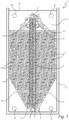
- the bio-filter unit 1 comprises a container 2 which is filled with filter media / filter elements 3.
- these filter elements 3 are flushing out from a vertical tube 5 implying that the container 2 in this moment is operated in a flushing / cleaning cycle.
- the filter elements 3 are being pumped up through the vertical tube 5, from the open input end 6 and towards the top 10 of the container 2 and out from the open output end 7, from where the filter elements 3 are settling towards the bottom 9 of the container 2.
- the driving force is provided by a pump 8, which may be arranged at different positions, but in this case is positioned at the bottom 9 of the container 2. In another situation, tubing may be provided from the bottom and to a pump 8 positioned under the container 2 but at the side.
- feeding lines 50 supplying water to the container 2, which water is intended to be treated in the bio-filter unit 1. It should be noted that also only one feeding line 50 may of course be used.
- the water flown into the container 2 comes from a regeneration filter or a pre-filter where particles have been removed.
- a perforated plate 12 is arranged inclined from the wall 13 of the container 2 towards a vertical centre line 11 of the container 2, and is inclined downwards towards the bottom 9 of the container 2. Moreover, the plate 12 is arranged in a full cross section around the vertical centre line 11, as viewed from the top 10 or the bottom 9 of the container 2. This implies that all filter elements are arranged to stay inside of the container 2 without passing the plate 12. Purified water passing through the perforated plate 12 is flown out through a water outflow 14, in this case two such water outflows 14, being arranged under the plate 12. The fraction of purified water is then be sent to a fish farming tank from the water outflows 14.
- an upper plate 15 is arranged inclined downwards from and around the open output end 7 of the vertical tube 5 and ends at a distance from a wall 13 of the container.
- the filter elements 3 pass or glide on the upper plate 15 and then settle down in the container 2.
- the upper plate 15 is, however, perforated so that contaminants and contaminated water flowing out from the open output end 7 of the vertical tube 5 may enter through the upper plate 15 to be flown out from a regeneration water outflow 16.
- This contaminated water fraction may then be sent either back to a pre-filter before the bio-filter 1 or e.g. to a regeneration filter where recirculation of water back to the bio-filter 1 may be performed.
- a recirculation flow from a pre-filter such as a disc or drum filter, may be flown into the top of the container 2, e.g. in two pipes, one on each side of the container 2.
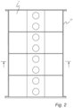
- bio-filter unit module framework 17 according to one embodiment of the present invention. Here several bio-filters 1 are shown from the top as linked together in the module framework 17.
Landscapes
- Life Sciences & Earth Sciences (AREA)
- Environmental Sciences (AREA)
- Biodiversity & Conservation Biology (AREA)
- Marine Sciences & Fisheries (AREA)
- Animal Husbandry (AREA)
- Chemical & Material Sciences (AREA)
- Chemical Kinetics & Catalysis (AREA)
- Microbiology (AREA)
- Hydrology & Water Resources (AREA)
- Engineering & Computer Science (AREA)
- Environmental & Geological Engineering (AREA)
- Water Supply & Treatment (AREA)
- Organic Chemistry (AREA)
- Zoology (AREA)
- Farming Of Fish And Shellfish (AREA)
Description
- The present invention relates to a bio-filter unit intended for a fish farming system.
- Different filters are used in fish farming systems today. Examples are different types of drum and disc filters and bio filters such as moving bed biofilm reactor (MBBR) and fixed bed biofilm reactor (FBBR). For example,
JP 63 77508 - One aim of the present invention is to provide an improved filter to be used in water recirculation systems intended for fish farming systems, wherein the improved filter provides several advantages in comparison to existing solutions. These advantages relate to e.g. providing an improved regeneration cycle for the water flow, the possibility of an increased total yield and thus degree of reuse of water and an increased efficiency when connecting and disconnecting a filter unit during e.g. a washing cycle or the like.
- The present invention is set out in the appended set of claims. The invention is defined by the independent claims. Embodiments are given by the dependent claims.
- The stated purpose above is achieved by a bio-filter unit intended for a fish farming system, said bio-filter unit comprising a container with a filter media and an inner architecture, said inner architecture comprising at least one vertical tube having an open input end and an open output end, wherein the bio-filter unit is connected to a pump enabling pumping liquid and filter media from a bottom of the container against a top of the container through said at least one vertical tube, wherein an upper plate is arranged inclined downwards from and around the open output end of the at least one vertical tube and ends at a distance from a wall of the container, wherein the upper plate is perforated and wherein a regeneration water outflow is arranged under the upper plate.
- The bio-filter unit according to the present invention combines the advantages of the MBBR and FBBR in one and the same unit. Furthermore, the bio-filter may establish a controlled and safe enviroment on a minimum of space, built in a modular system at a factory, and is easy to adapt to the right capacity and to assemble and dissamble. This is further discussed below.
- The bio-filter unit according to the present invention is intended to enable inner circulation of the filter media inside of the container. This concept according to the present invention provides a better cleaning cycle and thus regeneration and reuse of water in the entire system as the cleaning process is physically more effective and also provides the possibility of a more effective regeneration and cleaning cycle for a filter intended for a fish farming system.
- The bio-filter according to the present invention may be seen as a hybrid of a fixed bed filter and a moving bed filter. The bio-filter according to the present invention performs as a moving bed filter unit when a cleaning cycle is performed, i.e. when the pump flushes the filer media up through the vertical tube so that the filter media then is cleaned from contaminating material on the surfaces by physical movement or turbulent flow. During this cycle the filter media is flushed up through the vertical tube and then out through the same. As further discussed below, the contaminants or residues, such as e.g. particles, and water having a comparatively high concentration of contaminants may then be separated off by being filtered through one or more upper plates (net or grate), where a contaminated fraction may then be led to a regeneration filter unit or back to a pre-filter to enable a separation and possibly also a recirculation over the bio-filter unit. This flush or cleaning cycle and the time period therefore is further discussed below.
- Furthermore, the filter media exiting the vertical tube when being pumped up through the vertical tube then settle through the container and a purified water fraction is separated in a lower section of the container. This purified water fraction may then be led back to a fish farming tank.
- The standard arrangement used today includes a moving bed filter to enable particle removal and then a fixed bed filter to enable water purification. As may be understood from the description above, according to the present invention this is accomplished in one and the same bio-filter unit.
- Furthermore, it should be noted that "the filter media" according to the present invention may e.g. also be called filter substrate, filter elements or bio-(filter) elements or the like.
- To provide additional prior art it may be mentioned that in
US 5,681,472 there is disclosed a filter tank comprising a sand filter type. The filter tank comprises a filter bed. The treated filtrate is collected in a filtrate zone above the filter bed. This is one important difference when comparing with the present invention. InUS 5,681,472 the design is made to provide for purified water to be separated off in the top. This is the opposite to the direction of the present invention. According to the present invention water intended to be separated off for further regeneration, i.e. water which is not clean enough, is separated off in the upper part of the container. Purified water, however, is flown out from the container in the lower part of the container. As stated above, the bio-filter according to the present invention comprises a perforated upper plate which is arranged inclined downwards from and around the open output end of the at least one vertical tube and which ends at a distance from a wall of the container. Moreover, a regeneration water outflow is arranged under the upper plate. None of these features are provided in the sand filter according toUS 5,681,472 . Furthermore, it may also be said that the type of sand filter disclosed inUS 5,681,472 is not intended for large water flows, which is the case of the bio-filter according to the present invention. The bio-filter according to the present invention is intended to be used in fish farming systems where such large water flows are a fact. - Below the present invention is discussed in more detail and different embodiments are provided and explained.
- First of all, it should be noted that the pump to be used in connection with the bio-filter unit according to the present invention may be of different type and may be located at different positions. In
fig. 1 one alternative of placing is shown. According to one embodiment of the present invention a mammoth pump or air lift pump is connected to the bio-filter unit according to the present invention. Regardless of type, the principle according to the present invention is to provide enough power input to be able to lift or pump the filter elements up through the vertical tube. The pumping medium to be used may e.g. be air such as in an air lift pump. - The inner architecture of the present bio-filter unit may be of different type, geometry and size. The general principle of the present invention is to provide a uniform inner architecture, which may imply that a cross section of the bio-filter unit seen from the side and/or from the bottom and/or from the top provides a uniform inner architecture. This enables a uniform cleaning cycle when the filter media or filter elements settle down through the container outside of the vertical tube after having been pumped up through and out from the vertical tube.
- Furthermore, typically the operation is also performed in cycles. As an examples, during a cleaning cycle one filter element may have a retention time of around 3-5 minutes from one vertical point to about the same vertical point in the container, i.e. having been pumped up through the vertical tube from a given starting point and then settled to about the same starting point again. Subsequently to such a cycle then the entire bio-filter is run with the pump in an off mode to be in a fixed bed mode. This period may be kept from 30 minutes up to several hours, e.g. around 2 hours. Then the cleaning cycle in the moving bed mode is performed again.
- It should be noted that the filter elements may be of any suitable type, size and material according to the present invention. Also the vertical tube may be of different sizes and comprising different material. Furthermore, according to one specific embodiment of the present invention, the inner architecture comprises several vertical tubes. Moreover, according to yet another specific embodiment of the present invention, said at least one vertical tube, or vertical tubes, are arranged at or near a vertical centre line of the container. This is shown in
fig. 1 as one example and this arrangement is also in line with a uniform arrangement according to the present invention. - The bio-filter unit according to the present invention also enables to lead purified water, which has been filtered, back to a fish farming tank. This may be performed in different ways according to the present invention, however according to one embodiment a mechanical filter is arranged in a lower section of the container of the bio-filter unit. This mechanical filter may be arranged as a perforated disc around the vertical tube at a lower section of the container. This disc may also be seen as a plate. Therefore, according to one specific embodiment of the present invention, a plate is arranged inclined from a wall of the container towards a vertical centre line of the container, being inclined downwards towards the bottom of the container, and being in a full cross section of the container around the vertical centre line, i.e. wherein the plate extends around the entire circumference of the container. This plate arranged in a lower section of the container typically has a circular cross section to make up an entire cross section of the container at a lower position thereof. Moreover, this lower plate is suitably inclined downwards from the walls and towards the vertical tube. This shape may be seen as a cone upside-down when viewing the container in cross section and from the side.
- Furthermore, according to one specific embodiment of the present invention, the plate is perforated, such as forming a net or grate. As such purified water may penetrate through the perforated disc, while the filter elements are kept on top of the disc. Moreover, according to yet another embodiment a water outflow s arranged under the plate. The purified water which has been processed in the bio-filter unit according to the present invention may be led to a fish farming tank. This then constitutes part of the regeneration process of a fish farming system.
- It should be noted that any shape of the lower plate is possible, however the described alternative above has the advantage of providing a uniform settling of the filter elements which then are led back to the inlet of the vertical tube before being pumped up through the same in another cleaning cycle.
- As hinted above, according to one specific embodiment of the present invention, there may also be one or more upper plates arranged close to the outlet of the vertical tube. Therefore, according to one specific embodiment of the present invention, an upper plate is arranged inclined downwards from and around the open output end of the at least one vertical tube and ends at a distance from a wall of the container. Such an upper plate may also be seen as a disc provided around the vertical tube at the outlet of the vertical tube, however this one is inclined downwards from the centre and out against the wall, however of course only a distance so that the portions outside of the upper plate is free for settlement for the filter elements being pumped out from the vertical tube. Moreover, such an upper plate or disc typically has a circular cross section and is thus shaped like a cone with an inclination downwards and the top part around the vertical tube.
- Moreover, this plate(s) is intended as a receiving surface and filter part for contaminated filter elements and water flowing out from the vertical tube(s). Furthermore, suitably also this upper plate is perforated, such as being a net or grate. Then the contaminated water and particles which have been removed from the surface of the filter elements penetrates through the perforations and may be flown to a regeneration process. As understood, according to one specific embodiment of the present invention, a regeneration water outflow is arranged under the upper plate. The filter elements do not flow through this upper mechanical filter plate and thus settle inside of the container.
- The contaminated water flow and particles may be flown to a separate drum or disc filter or back to a pre-filter, which also may be a drum or disc filter, to enable regeneration also of this flow. Such a pre-filter may also constitute the first step where contaminated water and fish faeces from a fish tank is separated. The water fraction and particles after separation therein may then be flown to a bio-filter unit according to the present invention to enable further purification, separation and finally regeneration of the water flow.
- If the contaminated water flow with particles separated off in the bio-filter unit according to the present invention instead is flown to a separate drum or disc filter, such a unit may separate this and the water fraction may be sent back or recirculated back to the bio-filter unit. The particles, however, are removed. As may be understood, there are several different set-ups possible for incorporation of a bio-filter unit according to the present invention in a fish farming system.
- Also the step where contaminated water and particles are separated off in the bio-filter unit may constitute a part of a regeneration process of a fish farming system according to the present invention.
- The present invention is also directed to a bio-filter system comprising several bio-filter units according to the present invention, wherein each bio-filter unit is connectable to others in a module framework. One example thereof is shown in
fig. 2 . A module of bio-filter units according to the present invention may provide an arrangement where the bio-filter units may be connected to each other as uniform units one by one in the module framework. They may have one common outflow for the purified water flow being sent back to the fish farming tank. The same may be valid for a common output flow of contaminated water and particles. Also the inflow for contaminated water sent to the bio-filter units may be provided in one common input flow. - The bio-filter units should, however, also be seen as individual units. This type of configuration implies that one single or several bio-filter units may be disconnected during a rinse cycle or for maintenance while all others are in continuous operation. To connect or disconnect a bio-filter unit in such a module system is simple. Also to increase the capacity by incorporating more bio-filters are simple. Furthermore, the different bio-filter units may operate in different modes at the same time. Moreover, the bio-filter units may operate sequentially. This configuration according to the present invention enables an effective operation and also a high total yield of purified water being sent back to the fish farming tank(s). It should also be noted that the contaminated water flow and residues separated off in the bio-filter units may be sent to one pre-filter unit intended only for the entire module of bio-filter units.
- Furthermore, the present invention refers to a fish farming system comprising a fish farming tank and a general recirculation loop which comprises first a pre-filter, e.g. a disc or drum filter, enabling filtering off contaminants intended to be sent to waste and further recirculation of water (and some residues) and wherein the recirculation loop comprises a subsequent bio-filter unit or a bio-filter module system according to the present invention with one or more regeneration filter units with regeneration recirculation loop(s). The regeneration filter units may also be in the form of disc or drum filters. Moreover, these filters may be seen as polishing filters.
- Moreover, according to yet another embodiment, the fish farming system also comprises a unit for aeration of and separation of carbon dioxide before the general recirculation loop is completed and purified and aerated water is flown back to the fish farming tank.
- Furthermore, the present invention also refers to a method for the operation of a bio-filter unit according to the present invention, wherein the method comprises pumping liquid, thus water and possibly residues, and filter media up from a bottom of the container against a top of the container through said at least one vertical tube in sequences with a certain time range. As an example, this cleaning sequence may e.g. be performed once every 30 minutes up to every 2-3 hours. Moreover, the cleaning sequence may last from 1 to 5 minutes every time. Again, the method according to the present invention enables to operate the bio-filter unit according to the present invention to mimic both a moving bed filter and fixed bed filter in one operation cycle.
- In addition to the advantages mentioned above, the bio-filter unit and possible module according to the present invention also enables a simple back flushing operation without generating large amounts of rejects. Furthermore, the configuration also provides 100% control of washing the entire filter bed of elements when a back flushing is performed.
- In
fig. 1 there is shown one embodiment of abio-filter unit 1 according to the present invention. Thebio-filter unit 1 comprises acontainer 2 which is filled with filter media /filter elements 3. In this case thesefilter elements 3 are flushing out from avertical tube 5 implying that thecontainer 2 in this moment is operated in a flushing / cleaning cycle. Thefilter elements 3 are being pumped up through thevertical tube 5, from theopen input end 6 and towards the top 10 of thecontainer 2 and out from theopen output end 7, from where thefilter elements 3 are settling towards the bottom 9 of thecontainer 2. The driving force is provided by a pump 8, which may be arranged at different positions, but in this case is positioned at the bottom 9 of thecontainer 2. In another situation, tubing may be provided from the bottom and to a pump 8 positioned under thecontainer 2 but at the side. - Moreover, in this case there are two feeding
lines 50 supplying water to thecontainer 2, which water is intended to be treated in thebio-filter unit 1. It should be noted that also only onefeeding line 50 may of course be used. The water flown into thecontainer 2 comes from a regeneration filter or a pre-filter where particles have been removed. - Furthermore, a
perforated plate 12 is arranged inclined from thewall 13 of thecontainer 2 towards avertical centre line 11 of thecontainer 2, and is inclined downwards towards the bottom 9 of thecontainer 2. Moreover, theplate 12 is arranged in a full cross section around thevertical centre line 11, as viewed from the top 10 or the bottom 9 of thecontainer 2. This implies that all filter elements are arranged to stay inside of thecontainer 2 without passing theplate 12. Purified water passing through theperforated plate 12 is flown out through awater outflow 14, in this case twosuch water outflows 14, being arranged under theplate 12. The fraction of purified water is then be sent to a fish farming tank from thewater outflows 14. - Moreover, an
upper plate 15 is arranged inclined downwards from and around theopen output end 7 of thevertical tube 5 and ends at a distance from awall 13 of the container. Thefilter elements 3 pass or glide on theupper plate 15 and then settle down in thecontainer 2. Theupper plate 15 is, however, perforated so that contaminants and contaminated water flowing out from theopen output end 7 of thevertical tube 5 may enter through theupper plate 15 to be flown out from aregeneration water outflow 16. This contaminated water fraction may then be sent either back to a pre-filter before thebio-filter 1 or e.g. to a regeneration filter where recirculation of water back to thebio-filter 1 may be performed. A recirculation flow from a pre-filter, such as a disc or drum filter, may be flown into the top of thecontainer 2, e.g. in two pipes, one on each side of thecontainer 2. - In
fig. 2 there is shown a bio-filterunit module framework 17 according to one embodiment of the present invention. Hereseveral bio-filters 1 are shown from the top as linked together in themodule framework 17.
Claims (7)
- Bio-filter unit (1) intended for a fish farming system, said bio-filter unit (1) comprising a container (2) with a filter media (3) and an inner architecture, said inner architecture comprising at least one vertical tube (5) having an open input bottom end (6) and an open output top end (7), wherein the bio-filter unit (1) is connected to a pump (8) enabling pumping liquid and filter media (3) from a bottom (9) of the container (2) against a top (10) of the container (2) through said at least one vertical tube (5), characterised in thatan upper plate (15) is arranged inclined downwards from and around the open output top end (7) of the at least one vertical tube (5) and ends at a distance from a wall (13) of the container, wherein the upper plate (15) is perforated and wherein a regeneration water outflow (16) is arranged under the upper plate (15) in the upper part of the container (2), which enables contaminated water and particles separated from the filter media (3) to be flown from the container (2),wherein a plate (12) is arranged inclined from a wall (13) of the container (2) towards a vertical centre line (11) of the container (2), being inclined downwards towards the bottom (9) of the container (2), and wherein the plate (12) extends around the entire circumference of the container (2),wherein the plate (12) is perforated,and wherein a water outflow (14) is arranged under the plate (12).
- Bio-filter unit (1) according to claim 1, wherein the inner architecture comprises several vertical tubes (5).
- Bio-filter unit (1) according to claim 1 or 2, wherein said at least one vertical tube (5) is arranged at or near to a vertical centre line (11) of the container (2).
- Bio-filter system comprising several bio-filter units (1) according to any of claims 1-3, wherein each bio-filter unit (1) is connectable to others in a module framework (17).
- Fish farming system comprising a fish farming tank and a general recirculation loop which comprises first a pre-filter enabling filtering off contaminants intended to be sent to waste and further recirculation of water and wherein the recirculation loop comprises a subsequent bio-filter unit (1) according to any of claims 1-3 or a bio-filter system according to claim 4 with one or more regeneration filter units with regeneration recirculation loop(s).
- Fish farming system according to claim 5, wherein the fish farming system also comprises a unit for aeration of and separation of carbon dioxide before the general recirculation loop is completed and purified and aerated water is flowed back to the fish farming tank.
- Method for the operation of a bio-filter unit (1) according to any of claims 1-3, wherein the method comprises pumping liquid and filter media (3) up from a bottom (9) of the container (2) against a top (10) of the container (2) through said at least one vertical tube (5) in sequences with a certain time range.
Applications Claiming Priority (2)
| Application Number | Priority Date | Filing Date | Title |
|---|---|---|---|
| SE1851089 | 2018-09-14 | ||
| PCT/SE2019/050825 WO2020055304A1 (en) | 2018-09-14 | 2019-09-04 | Bio-filter unit for a fish farming system |
Publications (4)
| Publication Number | Publication Date |
|---|---|
| EP3849683A1 EP3849683A1 (en) | 2021-07-21 |
| EP3849683A4 EP3849683A4 (en) | 2022-04-20 |
| EP3849683C0 EP3849683C0 (en) | 2024-11-13 |
| EP3849683B1 true EP3849683B1 (en) | 2024-11-13 |
Family
ID=69776679
Family Applications (1)
| Application Number | Title | Priority Date | Filing Date |
|---|---|---|---|
| EP19859475.6A Active EP3849683B1 (en) | 2018-09-14 | 2019-09-04 | Bio-filter unit for a fish farming system |
Country Status (4)
| Country | Link |
|---|---|
| US (1) | US11560325B2 (en) |
| EP (1) | EP3849683B1 (en) |
| CN (1) | CN112638493A (en) |
| WO (1) | WO2020055304A1 (en) |
Families Citing this family (1)
| Publication number | Priority date | Publication date | Assignee | Title |
|---|---|---|---|---|
| CN113200598A (en) * | 2021-04-13 | 2021-08-03 | 中国科学院海洋研究所 | Self-cleaning fixed bed biological filter device for recirculating aquaculture and use method |
Family Cites Families (18)
| Publication number | Priority date | Publication date | Assignee | Title |
|---|---|---|---|---|
| DE1205918B (en) * | 1961-04-14 | 1965-11-25 | Forschungsgesellschaft Der Wab | Suspended matter contact system for cleaning water |
| US4197201A (en) | 1976-03-03 | 1980-04-08 | Rederiaktiebolaget Nordstjernan | Apparatus for the filtration of a suspension or emulsion |
| HU202124B (en) * | 1984-05-04 | 1991-02-28 | Magyar Asvanyolaj Es Foeldgaz | Method and apparatus for continuous filtering fluids on moving granular bed |
| JPS6377508A (en) * | 1986-09-20 | 1988-04-07 | Akashi Jiyouka:Kk | Moving bed type water treating apparatus |
| SE500004C2 (en) | 1991-07-12 | 1994-03-21 | Nordic Water Prod Ab | Method and apparatus for separating gas bubbles and granular filter media from a filtrate which has passed a filter bed |
| US6319413B1 (en) | 2000-04-20 | 2001-11-20 | Ashbrook Corporation | Method of filtering liquid using a vertical filter |
| US6605135B2 (en) * | 2001-09-26 | 2003-08-12 | Air Products And Chemicals, Inc. | Granular bed restraint system |
| US20060196440A1 (en) * | 2005-03-05 | 2006-09-07 | Oceanboy Farms, Inc. | Hatchery system and method |
| CN2801258Y (en) * | 2005-07-15 | 2006-08-02 | 陆双阳 | Vertical stainless steel water purification filter for household tap-water |
| CN101306268A (en) * | 2008-01-30 | 2008-11-19 | 北京市农业机械研究所 | Continuous fibrous globule filter and its filtering method |
| US20110065084A1 (en) * | 2008-05-12 | 2011-03-17 | Govind Rao | Integrated oxygen measurement and control for static culture vessels |
| NO346912B1 (en) * | 2008-09-24 | 2023-02-27 | Siemens Energy Inc | Water treatment procedures |
| WO2011052938A2 (en) * | 2009-10-26 | 2011-05-05 | 미라클워터 주식회사 | High speed filtration device using porous media, and backwash method thereof |
| US8585892B2 (en) * | 2010-01-13 | 2013-11-19 | Biofilter Systems, Llc | System and process for removing nitrogen compounds and odors from wastewater and wastewater treatment system |
| CN102849848B (en) * | 2012-09-26 | 2014-03-05 | 北京市环境保护科学研究院 | Internal circulation biological filter reactor and sewage treatment method |
| US9675916B2 (en) | 2012-10-04 | 2017-06-13 | Eaton Corporation | Servo-controlled backwash filter system |
| CN103623627A (en) * | 2013-11-25 | 2014-03-12 | 桂林理工大学 | Method for treating sewage by using biological active sand reactor |
| CN206325269U (en) * | 2016-12-06 | 2017-07-14 | 欧盛腾水处理技术(杭州)有限公司 | The continuous sand filtration apparatus of level stream |
-
2019
- 2019-09-04 CN CN201980057420.4A patent/CN112638493A/en active Pending
- 2019-09-04 WO PCT/SE2019/050825 patent/WO2020055304A1/en not_active Ceased
- 2019-09-04 EP EP19859475.6A patent/EP3849683B1/en active Active
- 2019-09-04 US US17/276,139 patent/US11560325B2/en active Active
Also Published As
| Publication number | Publication date |
|---|---|
| WO2020055304A1 (en) | 2020-03-19 |
| US20220048797A1 (en) | 2022-02-17 |
| CN112638493A (en) | 2021-04-09 |
| US11560325B2 (en) | 2023-01-24 |
| EP3849683C0 (en) | 2024-11-13 |
| EP3849683A4 (en) | 2022-04-20 |
| EP3849683A1 (en) | 2021-07-21 |
Similar Documents
| Publication | Publication Date | Title |
|---|---|---|
| US20220176276A1 (en) | Multilayer Media Bed Filter with Improved Backwash | |
| JP3652557B2 (en) | Filtration equipment backwash method | |
| US6319413B1 (en) | Method of filtering liquid using a vertical filter | |
| CN111135718A (en) | A sewage filtering device and filtering method | |
| US11560325B2 (en) | Bio-filter unit for a fish farming system | |
| CN210434134U (en) | Static separation device for suspended matters and sludge in waste water treated by kitchen waste processor | |
| KR100206647B1 (en) | Filter bed mobile filtration device | |
| JP3652567B2 (en) | Cleaning method for filtration equipment | |
| US5252230A (en) | Granulated filter for the filtration of fine graded suspensions | |
| US10022654B2 (en) | Gas-liquid distribution technique for water or wastewater filters using underdrains | |
| JP3178632U (en) | High speed precipitation filter | |
| CN101843997B (en) | Concentrated backwashing system for disc filter cloth filters | |
| CN215250245U (en) | An all-in-one machine for water treatment in aquaculture | |
| CN201356993Y (en) | Self-cleaning sand drift filter | |
| CN2907825Y (en) | Self-cleaning sand shifting filter | |
| CN107081001A (en) | A kind of fiber filter disc filtration system | |
| CN203886254U (en) | Biological quicksand filter for desalted water pretreatment system | |
| CN211069153U (en) | Light filter material filter tank | |
| JPH10202281A (en) | Wastewater treatment equipment | |
| CN213492427U (en) | Turbid water circulation treatment system of air flotation machine | |
| CN209161611U (en) | A kind of water body purification apparatus | |
| US20080121593A1 (en) | Filter System for Water and Waste Water | |
| JP6509764B2 (en) | Water treatment apparatus and operating method thereof | |
| US20040217066A1 (en) | Universal piping apparatus for use with a filtration device | |
| CN120787891A (en) | Circulating water culture system filtration equipment convenient to clearance |
Legal Events
| Date | Code | Title | Description |
|---|---|---|---|
| STAA | Information on the status of an ep patent application or granted ep patent |
Free format text: STATUS: THE INTERNATIONAL PUBLICATION HAS BEEN MADE |
|
| PUAI | Public reference made under article 153(3) epc to a published international application that has entered the european phase |
Free format text: ORIGINAL CODE: 0009012 |
|
| STAA | Information on the status of an ep patent application or granted ep patent |
Free format text: STATUS: REQUEST FOR EXAMINATION WAS MADE |
|
| 17P | Request for examination filed |
Effective date: 20210225 |
|
| AK | Designated contracting states |
Kind code of ref document: A1 Designated state(s): AL AT BE BG CH CY CZ DE DK EE ES FI FR GB GR HR HU IE IS IT LI LT LU LV MC MK MT NL NO PL PT RO RS SE SI SK SM TR |
|
| DAV | Request for validation of the european patent (deleted) | ||
| DAX | Request for extension of the european patent (deleted) | ||
| A4 | Supplementary search report drawn up and despatched |
Effective date: 20220317 |
|
| RIC1 | Information provided on ipc code assigned before grant |
Ipc: C02F 3/06 20060101ALI20220311BHEP Ipc: B01D 35/12 20060101ALI20220311BHEP Ipc: A01K 61/10 20170101ALI20220311BHEP Ipc: B01D 24/46 20060101AFI20220311BHEP |
|
| STAA | Information on the status of an ep patent application or granted ep patent |
Free format text: STATUS: EXAMINATION IS IN PROGRESS |
|
| 17Q | First examination report despatched |
Effective date: 20230130 |
|
| GRAP | Despatch of communication of intention to grant a patent |
Free format text: ORIGINAL CODE: EPIDOSNIGR1 |
|
| STAA | Information on the status of an ep patent application or granted ep patent |
Free format text: STATUS: GRANT OF PATENT IS INTENDED |
|
| INTG | Intention to grant announced |
Effective date: 20240708 |
|
| GRAS | Grant fee paid |
Free format text: ORIGINAL CODE: EPIDOSNIGR3 |
|
| GRAA | (expected) grant |
Free format text: ORIGINAL CODE: 0009210 |
|
| STAA | Information on the status of an ep patent application or granted ep patent |
Free format text: STATUS: THE PATENT HAS BEEN GRANTED |
|
| AK | Designated contracting states |
Kind code of ref document: B1 Designated state(s): AL AT BE BG CH CY CZ DE DK EE ES FI FR GB GR HR HU IE IS IT LI LT LU LV MC MK MT NL NO PL PT RO RS SE SI SK SM TR |
|
| REG | Reference to a national code |
Ref country code: GB Ref legal event code: FG4D |
|
| REG | Reference to a national code |
Ref country code: CH Ref legal event code: EP |
|
| REG | Reference to a national code |
Ref country code: IE Ref legal event code: FG4D |
|
| REG | Reference to a national code |
Ref country code: DE Ref legal event code: R096 Ref document number: 602019062054 Country of ref document: DE |
|
| U01 | Request for unitary effect filed |
Effective date: 20241213 |
|
| U07 | Unitary effect registered |
Designated state(s): AT BE BG DE DK EE FI FR IT LT LU LV MT NL PT RO SE SI Effective date: 20241223 |
|
| PG25 | Lapsed in a contracting state [announced via postgrant information from national office to epo] |
Ref country code: IS Free format text: LAPSE BECAUSE OF FAILURE TO SUBMIT A TRANSLATION OF THE DESCRIPTION OR TO PAY THE FEE WITHIN THE PRESCRIBED TIME-LIMIT Effective date: 20250313 Ref country code: HR Free format text: LAPSE BECAUSE OF FAILURE TO SUBMIT A TRANSLATION OF THE DESCRIPTION OR TO PAY THE FEE WITHIN THE PRESCRIBED TIME-LIMIT Effective date: 20241113 |
|
| PG25 | Lapsed in a contracting state [announced via postgrant information from national office to epo] |
Ref country code: ES Free format text: LAPSE BECAUSE OF FAILURE TO SUBMIT A TRANSLATION OF THE DESCRIPTION OR TO PAY THE FEE WITHIN THE PRESCRIBED TIME-LIMIT Effective date: 20241113 |
|
| PG25 | Lapsed in a contracting state [announced via postgrant information from national office to epo] |
Ref country code: GR Free format text: LAPSE BECAUSE OF FAILURE TO SUBMIT A TRANSLATION OF THE DESCRIPTION OR TO PAY THE FEE WITHIN THE PRESCRIBED TIME-LIMIT Effective date: 20250214 |
|
| PG25 | Lapsed in a contracting state [announced via postgrant information from national office to epo] |
Ref country code: PL Free format text: LAPSE BECAUSE OF FAILURE TO SUBMIT A TRANSLATION OF THE DESCRIPTION OR TO PAY THE FEE WITHIN THE PRESCRIBED TIME-LIMIT Effective date: 20241113 |
|
| PG25 | Lapsed in a contracting state [announced via postgrant information from national office to epo] |
Ref country code: RS Free format text: LAPSE BECAUSE OF FAILURE TO SUBMIT A TRANSLATION OF THE DESCRIPTION OR TO PAY THE FEE WITHIN THE PRESCRIBED TIME-LIMIT Effective date: 20250213 |
|
| PG25 | Lapsed in a contracting state [announced via postgrant information from national office to epo] |
Ref country code: SM Free format text: LAPSE BECAUSE OF FAILURE TO SUBMIT A TRANSLATION OF THE DESCRIPTION OR TO PAY THE FEE WITHIN THE PRESCRIBED TIME-LIMIT Effective date: 20241113 |
|
| PG25 | Lapsed in a contracting state [announced via postgrant information from national office to epo] |
Ref country code: SK Free format text: LAPSE BECAUSE OF FAILURE TO SUBMIT A TRANSLATION OF THE DESCRIPTION OR TO PAY THE FEE WITHIN THE PRESCRIBED TIME-LIMIT Effective date: 20241113 |
|
| PG25 | Lapsed in a contracting state [announced via postgrant information from national office to epo] |
Ref country code: CZ Free format text: LAPSE BECAUSE OF FAILURE TO SUBMIT A TRANSLATION OF THE DESCRIPTION OR TO PAY THE FEE WITHIN THE PRESCRIBED TIME-LIMIT Effective date: 20241113 |
|
| PLBE | No opposition filed within time limit |
Free format text: ORIGINAL CODE: 0009261 |
|
| STAA | Information on the status of an ep patent application or granted ep patent |
Free format text: STATUS: NO OPPOSITION FILED WITHIN TIME LIMIT |
|
| U20 | Renewal fee for the european patent with unitary effect paid |
Year of fee payment: 7 Effective date: 20250815 |
|
| PGFP | Annual fee paid to national office [announced via postgrant information from national office to epo] |
Ref country code: NO Payment date: 20250820 Year of fee payment: 7 |
|
| 26N | No opposition filed |
Effective date: 20250814 |
|
| PGFP | Annual fee paid to national office [announced via postgrant information from national office to epo] |
Ref country code: GB Payment date: 20251030 Year of fee payment: 7 |
|
| PGFP | Annual fee paid to national office [announced via postgrant information from national office to epo] |
Ref country code: IE Payment date: 20251126 Year of fee payment: 7 |
|
| REG | Reference to a national code |
Ref country code: CH Ref legal event code: H13 Free format text: ST27 STATUS EVENT CODE: U-0-0-H10-H13 (AS PROVIDED BY THE NATIONAL OFFICE) Effective date: 20260425 |