EP3849493B1 - Tub with swirl ports and dispenser - Google Patents
Tub with swirl ports and dispenser Download PDFInfo
- Publication number
- EP3849493B1 EP3849493B1 EP19859837.7A EP19859837A EP3849493B1 EP 3849493 B1 EP3849493 B1 EP 3849493B1 EP 19859837 A EP19859837 A EP 19859837A EP 3849493 B1 EP3849493 B1 EP 3849493B1
- Authority
- EP
- European Patent Office
- Prior art keywords
- dispenser
- flow
- bathtub
- liquid
- assembly
- Prior art date
- Legal status (The legal status is an assumption and is not a legal conclusion. Google has not performed a legal analysis and makes no representation as to the accuracy of the status listed.)
- Active
Links
Images











Classifications
-
- A—HUMAN NECESSITIES
- A61—MEDICAL OR VETERINARY SCIENCE; HYGIENE
- A61H—PHYSICAL THERAPY APPARATUS, e.g. DEVICES FOR LOCATING OR STIMULATING REFLEX POINTS IN THE BODY; ARTIFICIAL RESPIRATION; MASSAGE; BATHING DEVICES FOR SPECIAL THERAPEUTIC OR HYGIENIC PURPOSES OR SPECIFIC PARTS OF THE BODY
- A61H33/00—Bathing devices for special therapeutic or hygienic purposes
- A61H33/0087—Therapeutic baths with agitated or circulated water
-
- A—HUMAN NECESSITIES
- A61—MEDICAL OR VETERINARY SCIENCE; HYGIENE
- A61H—PHYSICAL THERAPY APPARATUS, e.g. DEVICES FOR LOCATING OR STIMULATING REFLEX POINTS IN THE BODY; ARTIFICIAL RESPIRATION; MASSAGE; BATHING DEVICES FOR SPECIAL THERAPEUTIC OR HYGIENIC PURPOSES OR SPECIFIC PARTS OF THE BODY
- A61H33/00—Bathing devices for special therapeutic or hygienic purposes
- A61H33/0095—Arrangements for varying the temperature of the liquid
-
- A—HUMAN NECESSITIES
- A61—MEDICAL OR VETERINARY SCIENCE; HYGIENE
- A61H—PHYSICAL THERAPY APPARATUS, e.g. DEVICES FOR LOCATING OR STIMULATING REFLEX POINTS IN THE BODY; ARTIFICIAL RESPIRATION; MASSAGE; BATHING DEVICES FOR SPECIAL THERAPEUTIC OR HYGIENIC PURPOSES OR SPECIFIC PARTS OF THE BODY
- A61H33/00—Bathing devices for special therapeutic or hygienic purposes
- A61H33/04—Appliances for sand, mud, wax or foam baths; Appliances for metal baths, e.g. using metal salt solutions
-
- A—HUMAN NECESSITIES
- A61—MEDICAL OR VETERINARY SCIENCE; HYGIENE
- A61H—PHYSICAL THERAPY APPARATUS, e.g. DEVICES FOR LOCATING OR STIMULATING REFLEX POINTS IN THE BODY; ARTIFICIAL RESPIRATION; MASSAGE; BATHING DEVICES FOR SPECIAL THERAPEUTIC OR HYGIENIC PURPOSES OR SPECIFIC PARTS OF THE BODY
- A61H33/00—Bathing devices for special therapeutic or hygienic purposes
- A61H33/60—Components specifically designed for the therapeutic baths of groups A61H33/00
- A61H33/6005—Special constructive structural details of the bathtub, e.g. of the walls or supporting structure
-
- A—HUMAN NECESSITIES
- A61—MEDICAL OR VETERINARY SCIENCE; HYGIENE
- A61H—PHYSICAL THERAPY APPARATUS, e.g. DEVICES FOR LOCATING OR STIMULATING REFLEX POINTS IN THE BODY; ARTIFICIAL RESPIRATION; MASSAGE; BATHING DEVICES FOR SPECIAL THERAPEUTIC OR HYGIENIC PURPOSES OR SPECIFIC PARTS OF THE BODY
- A61H33/00—Bathing devices for special therapeutic or hygienic purposes
- A61H33/60—Components specifically designed for the therapeutic baths of groups A61H33/00
- A61H33/601—Inlet to the bath
-
- A—HUMAN NECESSITIES
- A61—MEDICAL OR VETERINARY SCIENCE; HYGIENE
- A61H—PHYSICAL THERAPY APPARATUS, e.g. DEVICES FOR LOCATING OR STIMULATING REFLEX POINTS IN THE BODY; ARTIFICIAL RESPIRATION; MASSAGE; BATHING DEVICES FOR SPECIAL THERAPEUTIC OR HYGIENIC PURPOSES OR SPECIFIC PARTS OF THE BODY
- A61H33/00—Bathing devices for special therapeutic or hygienic purposes
- A61H33/60—Components specifically designed for the therapeutic baths of groups A61H33/00
- A61H33/601—Inlet to the bath
- A61H33/6015—Cascade massage
-
- A—HUMAN NECESSITIES
- A61—MEDICAL OR VETERINARY SCIENCE; HYGIENE
- A61H—PHYSICAL THERAPY APPARATUS, e.g. DEVICES FOR LOCATING OR STIMULATING REFLEX POINTS IN THE BODY; ARTIFICIAL RESPIRATION; MASSAGE; BATHING DEVICES FOR SPECIAL THERAPEUTIC OR HYGIENIC PURPOSES OR SPECIFIC PARTS OF THE BODY
- A61H33/00—Bathing devices for special therapeutic or hygienic purposes
- A61H33/60—Components specifically designed for the therapeutic baths of groups A61H33/00
- A61H33/601—Inlet to the bath
- A61H33/6021—Nozzles
- A61H33/6063—Specifically adapted for fitting in bathtub walls
-
- A—HUMAN NECESSITIES
- A61—MEDICAL OR VETERINARY SCIENCE; HYGIENE
- A61H—PHYSICAL THERAPY APPARATUS, e.g. DEVICES FOR LOCATING OR STIMULATING REFLEX POINTS IN THE BODY; ARTIFICIAL RESPIRATION; MASSAGE; BATHING DEVICES FOR SPECIAL THERAPEUTIC OR HYGIENIC PURPOSES OR SPECIFIC PARTS OF THE BODY
- A61H33/00—Bathing devices for special therapeutic or hygienic purposes
- A61H33/60—Components specifically designed for the therapeutic baths of groups A61H33/00
- A61H33/6068—Outlet from the bath
- A61H33/6073—Intake mouths for recirculation of fluid in whirlpool baths
-
- A—HUMAN NECESSITIES
- A61—MEDICAL OR VETERINARY SCIENCE; HYGIENE
- A61H—PHYSICAL THERAPY APPARATUS, e.g. DEVICES FOR LOCATING OR STIMULATING REFLEX POINTS IN THE BODY; ARTIFICIAL RESPIRATION; MASSAGE; BATHING DEVICES FOR SPECIAL THERAPEUTIC OR HYGIENIC PURPOSES OR SPECIFIC PARTS OF THE BODY
- A61H33/00—Bathing devices for special therapeutic or hygienic purposes
- A61H2033/0037—Arrangement for cleaning the fluid during use
-
- A—HUMAN NECESSITIES
- A61—MEDICAL OR VETERINARY SCIENCE; HYGIENE
- A61H—PHYSICAL THERAPY APPARATUS, e.g. DEVICES FOR LOCATING OR STIMULATING REFLEX POINTS IN THE BODY; ARTIFICIAL RESPIRATION; MASSAGE; BATHING DEVICES FOR SPECIAL THERAPEUTIC OR HYGIENIC PURPOSES OR SPECIFIC PARTS OF THE BODY
- A61H33/00—Bathing devices for special therapeutic or hygienic purposes
- A61H33/005—Electrical circuits therefor
- A61H2033/0083—Illumination
-
- A—HUMAN NECESSITIES
- A61—MEDICAL OR VETERINARY SCIENCE; HYGIENE
- A61H—PHYSICAL THERAPY APPARATUS, e.g. DEVICES FOR LOCATING OR STIMULATING REFLEX POINTS IN THE BODY; ARTIFICIAL RESPIRATION; MASSAGE; BATHING DEVICES FOR SPECIAL THERAPEUTIC OR HYGIENIC PURPOSES OR SPECIFIC PARTS OF THE BODY
- A61H33/00—Bathing devices for special therapeutic or hygienic purposes
- A61H33/04—Appliances for sand, mud, wax or foam baths; Appliances for metal baths, e.g. using metal salt solutions
- A61H2033/048—Baths using solutions, e.g. salts
-
- A—HUMAN NECESSITIES
- A61—MEDICAL OR VETERINARY SCIENCE; HYGIENE
- A61H—PHYSICAL THERAPY APPARATUS, e.g. DEVICES FOR LOCATING OR STIMULATING REFLEX POINTS IN THE BODY; ARTIFICIAL RESPIRATION; MASSAGE; BATHING DEVICES FOR SPECIAL THERAPEUTIC OR HYGIENIC PURPOSES OR SPECIFIC PARTS OF THE BODY
- A61H2201/00—Characteristics of apparatus not provided for in the preceding codes
- A61H2201/01—Constructive details
- A61H2201/0157—Constructive details portable
-
- A—HUMAN NECESSITIES
- A61—MEDICAL OR VETERINARY SCIENCE; HYGIENE
- A61H—PHYSICAL THERAPY APPARATUS, e.g. DEVICES FOR LOCATING OR STIMULATING REFLEX POINTS IN THE BODY; ARTIFICIAL RESPIRATION; MASSAGE; BATHING DEVICES FOR SPECIAL THERAPEUTIC OR HYGIENIC PURPOSES OR SPECIFIC PARTS OF THE BODY
- A61H2201/00—Characteristics of apparatus not provided for in the preceding codes
- A61H2201/01—Constructive details
- A61H2201/0188—Illumination related features
-
- A—HUMAN NECESSITIES
- A61—MEDICAL OR VETERINARY SCIENCE; HYGIENE
- A61H—PHYSICAL THERAPY APPARATUS, e.g. DEVICES FOR LOCATING OR STIMULATING REFLEX POINTS IN THE BODY; ARTIFICIAL RESPIRATION; MASSAGE; BATHING DEVICES FOR SPECIAL THERAPEUTIC OR HYGIENIC PURPOSES OR SPECIFIC PARTS OF THE BODY
- A61H2201/00—Characteristics of apparatus not provided for in the preceding codes
- A61H2201/02—Characteristics of apparatus not provided for in the preceding codes heated or cooled
- A61H2201/0207—Characteristics of apparatus not provided for in the preceding codes heated or cooled heated
-
- A—HUMAN NECESSITIES
- A61—MEDICAL OR VETERINARY SCIENCE; HYGIENE
- A61H—PHYSICAL THERAPY APPARATUS, e.g. DEVICES FOR LOCATING OR STIMULATING REFLEX POINTS IN THE BODY; ARTIFICIAL RESPIRATION; MASSAGE; BATHING DEVICES FOR SPECIAL THERAPEUTIC OR HYGIENIC PURPOSES OR SPECIFIC PARTS OF THE BODY
- A61H2201/00—Characteristics of apparatus not provided for in the preceding codes
- A61H2201/50—Control means thereof
- A61H2201/5023—Interfaces to the user
-
- A—HUMAN NECESSITIES
- A61—MEDICAL OR VETERINARY SCIENCE; HYGIENE
- A61H—PHYSICAL THERAPY APPARATUS, e.g. DEVICES FOR LOCATING OR STIMULATING REFLEX POINTS IN THE BODY; ARTIFICIAL RESPIRATION; MASSAGE; BATHING DEVICES FOR SPECIAL THERAPEUTIC OR HYGIENIC PURPOSES OR SPECIFIC PARTS OF THE BODY
- A61H2201/00—Characteristics of apparatus not provided for in the preceding codes
- A61H2201/50—Control means thereof
- A61H2201/5023—Interfaces to the user
- A61H2201/5043—Displays
- A61H2201/5046—Touch screens
Definitions
- the present invention relates to a bathtub assembly with water circulation features and, in particular, to a bathtub assembly that dispenses a substance into the tub and creates a directed flow of water within the tub.
- Bathtubs incorporating various therapeutic and/or recreational features such as spa jets for massage and aeration and associated circulation systems, are known in the art, such as from US 2004168248 A1 , and are becoming increasingly popular in the market.
- Such massage/aeration jets are typically similar to jets utilized in larger spa tubs and are forceful.
- the circulation systems utilized to create flow through the jets can be loud.
- the noise and turbulence created by these systems may not be found to be relaxing or soothing by some users and may detract from the overall bathing experience for some users.
- the present invention is directed to a bathtub assembly according to claims 1 and 5 and a method of operating a bathtub assembly according to claim 12.
- a bathtub assembly that enhances the soothing and relaxation benefits of the bathing experience.
- the bathtub assembly incorporates a water circulation system and directed flow nozzles for creating a directed flow or stream of water within the bath for soothing hydromassage and relaxation; a dispenser assembly that provides for the addition, dissolution and/or mixing, and distribution of therapeutic substances directly into the bath through use of the water circulation system and via a soothing and relaxing waterfall assembly; and various lighting features for further enhancing the soothing and relaxation benefits of the bathing experience.
- the bathtub assembly also includes simple controls for operating the water circulation, dispenser, and lighting functions of the bathtub assembly. The controls may be incorporated into a touchscreen panel mounted on the bathtub assembly.
- a bathtub assembly includes a bathtub shell defining an interior cavity configured to contain a volume of liquid, the bathtub shell comprising an upper rim at least partially surrounding the interior cavity and having at least one dispenser flow opening defined therein; a circulation system in communication with the interior cavity of the bathtub shell, the circulation system being configured to create a flow of the liquid to and from the interior cavity of the bathtub shell; a housing in fluid communication between the circulation system and the interior cavity of the bathtub shell, the housing being connected to the bathtub shell at the at least one dispenser flow opening and configured to convey at least a portion of the flow of the liquid created by the circulation system into the interior cavity of the bathtub shell through the at least one dispenser flow opening; a dispenser assembly in fluid communication between the circulation system and the housing, the dispenser assembly being configured to contain a substance therein and to expose the substance to the at least a portion of the flow of the liquid conveyed to the at least one dispenser flow opening such that the substance is introduced into the volume of liquid in the interior cavity of the bathtub shell via
- a bathtub assembly includes a bathtub shell defining an interior cavity configured to contain a volume of liquid, the bathtub shell having at least one dispenser flow opening and a plurality of directed flow openings defined therein; a circulation system in communication with the interior cavity of the bathtub shell, the circulation system being configured to create a flow of the liquid to and from the interior cavity of the bathtub shell; a plurality of directed flow jets in fluid communication between the circulation system and the interior cavity of the bathtub shell, the plurality of directed flow jets being configured to convey at least a first portion of the flow of the liquid through the directed flow openings to create a directed flow of the liquid within the interior cavity of the bathtub shell; a housing in fluid communication between the circulation system and the interior cavity of the bathtub shell, the housing being connected to the bathtub shell at the at least one dispenser flow opening and configured to convey a second portion of the flow of the liquid created by the circulation system into the interior cavity of the bathtub shell through the at least one dispenser flow opening; a dispenser assembly in fluid communication between the
- a method of operating a bathtub assembly includes providing a bathtub assembly.
- the bathtub assembly includes a bathtub shell defining an interior cavity configured to contain a volume of liquid, the bathtub shell having at least one dispenser flow opening and a plurality of directed flow openings defined therein; a circulation system in communication with the interior cavity of the bathtub shell, the circulation system being configured to create a flow of the liquid to and from the interior cavity of the bathtub shell; a plurality of directed flow jets in fluid communication between the circulation system and the interior cavity of the bathtub shell, the plurality of directed flow jets being configured to convey at least a first portion of the flow of the liquid through the directed flow openings to create a directed flow of the liquid within the interior cavity of the bathtub shell; a housing in fluid communication between the circulation system and the interior cavity of the bathtub shell, the housing being connected to the bathtub shell at the at least one dispenser flow opening and configured to convey a second portion of the flow of the liquid created by the circulation system into the interior cavity of the bathtub shell through the at least
- the method further includes filling the interior cavity of the bathtub shell with the volume of liquid; inserting the substance into the dispenser assembly; activating the circulation system to create the flow of the liquid to and from the interior cavity of the bathtub shell through the directed flow jets to form the directed flow of the liquid within the interior cavity of the bathtub shell; and operating the valve to allow the second portion of the flow of the liquid to pass through the dispenser assembly, the housing, and the at least one dispenser flow opening to introduce the substance to the volume of liquid in the interior cavity of the bathtub shell via the at least one dispenser flow opening.
- the bathtub assembly 100 includes an inner shell 101 and an outer shell 102.
- the inner shell 101 defines an interior cavity of the bathtub assembly 100 for containing a volume of liquid, in particular water, sufficiently large for a user to bathe in while fully or mostly immersed in the water.
- the assembly 100 includes a drain 103 in communication with the interior cavity of the inner shell 101 and connected to a drain pipe for draining the volume of liquid from the interior cavity after use of the bathtub assembly 100 is complete.
- the outer shell 102 defines the exterior of the bathtub assembly 100.
- the inner shell 101 and the outer shell 102 of the bathtub assembly 100 are made from a molded acrylic material.
- the inner shell 101 and outer shell 102 may be made from any material known to be suitable to those having ordinary skill in the art. It is also to be appreciated that the inner shell 101 is disposed within the outer shell 102 and, as such, the exterior surface of the inner shell 101 and any internal components of the bathtub assembly 100 affixed to the exterior surface of the inner shell 101, as will be discussed below, will be hidden from view in the bathtub assembly 100.
- the bathtub assembly 100 may be utilized as an indoor bathtub as frequently found in home bathrooms.
- the bathtub assembly 100 may be a recreational spa assembly (i.e., "hot tub") configured for outdoor and/or indoor use, a portable tub assembly for use in homes, physical training facilities, and/or medical facilities, and/or a spa assembly configured for use in multiple applications.
- a recreational spa assembly i.e., "hot tub”
- portable tub assembly for use in homes, physical training facilities, and/or medical facilities
- a spa assembly configured for use in multiple applications.
- the inner shell 101 also includes an upper rim 104 at least partially surrounding the perimeter of the inner shell 101 and the interior cavity.
- the upper rim 104 completely surrounds the perimeter of the inner shell 101 and the interior cavity.
- a plurality of directed flow openings 105 are formed in the inner shell 101 extending through the inner shell 101 from an exterior surface thereof to a surface of the interior cavity.
- the directed flow openings 105 provide for the communication of directed flow jets 120, shown in FIG. 3 , with the interior cavity of the inner shell 101.
- the directed flow openings 105 are defined in the lateral sides of the inner shell 101 approximately midway along the height of the inner shell 101.
- At least one dispenser flow opening 107 or waterfall opening is also formed in the inner shell 101 approximately midway along the length of one of the lateral sides of the inner shell and proximate to the top of the interior cavity, i.e., slightly below the upper rim 104.
- the dispenser flow opening 107 provides for the communication of a dispenser and waterfall assembly 150, as shown in FIG. 3 , with the interior cavity of the inner shell 101.
- the dispenser flow opening 107 is positioned directly below a control panel 300.
- At least one suction opening 106 is also formed in the inner shell 101 directly below the dispenser flow opening 107.
- the suction opening 106 provides for the communication of a suction fitting / dispenser overflow drain 200, as shown in FIG. 3 , with the interior cavity of the inner shell 101. It is to be appreciated that the size and shape of the inner shell 101 and the outer shell 102, as well as the size, shape, positioning, and arrangement of the above-mentioned openings 105, 106, 107, may be varied from the illustrated example in any manner found to be suitable to one having ordinary skill in the art.
- the bathtub assembly 100 may further include a support frame 108 positioned under the inner shell 101 and within the outer shell 102 for supporting the bathtub assembly 100 on a floor surface and distributing the weight of the bathtub assembly 100, the volume of liquid, and the user along the floor surface.
- the bathtub assembly 100 includes a circulation system 110 in communication with the interior cavity of the inner shell 101 via the above-mentioned openings 105, 106, 107.
- the circulation system 110 is configured to create a circulating flow of the liquid to and from the interior cavity of the inner shell 101.
- the circulation system 110 includes a pump 111 for creating a pressurized flow of the liquid within a piping system.
- the piping system includes a directed flow pipeline 112 for conveying the pressurized flow of liquid from the pump 111 to a plurality of directed flow jets 120, a suction pipeline 113 for conveying a return flow of the liquid from the interior cavity of the inner shell 101 to the pump 111 via a suction fitting / dispenser overflow drain 200, and a dispenser pipeline 114 for conveying the pressurized flow of liquid from the pump 111 to a dispenser/waterfall assembly 150.
- the dispenser pipeline 114 is branched from the directed flow pipeline 112, and a valve 115 is provided for selectively controlling the flow of liquid to the dispenser/waterfall assembly 150.
- the valve 115 may be an electrically operated and remotely operable valve of any type found to be suitable to those having ordinary skill in the art.
- the pump 111 operates silently or with minimal noise and without air compression, such that the only appreciable noise created by the circulation system 110 is the sound of flowing liquid moving into and around the interior cavity of the inner shell 101.
- the circulation system 1 10 also includes a heater (not shown) for heating or maintaining the temperature of the liquid as it is circulated to and from the interior cavity of the inner shell 101.
- the function of the pump 111 and the function of the heater may be adjusted according to the user's preferences.
- the bathtub assembly 100 also includes a control panel 300 rotatably mounted on the upper rim 104 of the inner shell 101.
- the control panel 300 includes a number of touchscreen controls 302, shown in FIGS. 27 and 28 , that are operated by the user to control the circulation system 110 and the lighting features of the bathtub assembly 100, as will be discussed in further detail below.
- the control panel 300 is connected to the upper rim 104 adjacent to and directly above the dispenser flow opening 107. When activated via the control panel 300, the pump 111 will create a pressurized flow of the liquid through the directed flow pipeline 112 to the directed flow jets 120.
- the circulation system 110 may include an inline heater for heating the recirculated flow of liquid.
- the pipelines 112, 113, 114 may include antibacterial additives for cleaning the liquid as the liquid is re-circulated.
- the constant re-circulating flow of liquid into the interior cavity of the inner shell 101 via the directed flow jets 120 and out of the interior cavity of the inner shell 101 via the suction fitting / dispenser overflow drain 200 creates a directional flow of the liquid within the interior cavity.
- the directed flow jets 120 are further configured to angle the flow of liquid into the interior cavity along the sides of the inner shell 101 in a swirling or circulation motion to create a pleasing and relaxing stream of the liquid moving over and around the user.
- the directed flow of the liquid through the directed flow jets 120 offers a hydromassage benefit to the user without directly targeting a specific part of the user's body and without relying on powerful, turbulent jets of liquid or air and liquid.
- the speed/intensity of the directed flow of liquid may be set to the user's preference via a control incorporated in the control panel 300.
- the circulation system 110 also conveys the liquid to the dispenser/waterfall assembly 150 through the dispenser pipeline 114.
- Flow to the dispenser/waterfall assembly 150 is selectively controlled by the valve 115, which may be activated or de-activated to permit flow through the dispenser pipeline via a control incorporated in the control panel 300.
- the dispenser/waterfall assembly 150 provides for the dissolution, mixing, and/or entrainment and the subsequent distribution of substances, such as bath salts, herbs, aromatherapy, cleaning agents, or combinations of such substances, into the interior cavity of the inner shell 101 and for the creation of a flow of liquid carrying the substance or substances into the interior cavity of the inner shell in the form of a soothing, pleasant waterfall W.
- the valve 115 is operated, via the control panel 300, to open flow through the dispenser pipeline 114 to the dispenser/waterfall assembly 150.
- the dispenser/waterfall assembly 150 is loaded with the substance by a user such that the flow of liquid into the dispenser/waterfall assembly 150 is mixed with the substance and is then directed into the interior cavity of the inner shell 101 by the dispenser/waterfall assembly 150 in the form of a waterfall W.
- the bathtub assembly 100 includes a plurality of directed flow or "swirl" jets 120 distributed around the inner shell 101 and in fluid communication between the circulation system 1 10 and the interior cavity of the inner shell 101.
- the directed flow jets 120 convey at least a portion of the flow of the liquid created by the circulation system 110 into the interior cavity of the inner shell 101 through the plurality of directed flow openings 105 to create the directed flow of liquid within the interior cavity of the inner shell 101.
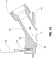
- each directed flow jet 120 includes an inlet 121 connected to a branch of the directed flow pipeline 112 (shown in FIG. 3 ) and an outlet 122 that opens into the interior cavity of the inner shell 101.
- a flow passage 124 is defined in the directed flow jet 120 between the inlet 121 and the outlet 122.
- a flange 123 surrounds the outlet 122. The flange 123 is directly affixed to an exterior surface of the inner shell 101 at at least one of the directed flow openings 105 in order to connect the directed flow jet 120 to the inner shell 101.
- the flange 123 is offset from an end of the outlet 122, and the outlet 122 has a shape, such as an oval or elliptical shape, corresponding to the shape of the directed flow opening 105 such that the outlet 122 extends into the directed flow opening 105 and terminates flush with or substantially flush with the interior surface of the inner shell 101, as shown in FIG. 9 , thus providing for direct fluid communication between the flow passage 124 and the interior cavity of the inner shell 101.
- the flow passage 124 extends at an angle A with respect to the flange 123 and the local portion of the inner shell 101 in order to form the directed flow of liquid within the interior cavity discussed above with reference to FIGS. 6 and 7.
- the angle A is approximately 15°-45°, more particularly approximately 25°-35°, and more particularly approximately 30° in order to form a directed flow of liquid at a corresponding angle within the interior cavity along the interior surface of the inner shell 101. It is to be appreciated that the angle A may be any angle found to be suitable to those having ordinary skill in the art for creating the directed flow of the liquid.
- the flange 123 is adhered directly to an exterior surface of the inner shell 101 with a suitable adhesive, such as a silicon glue.
- a suitable adhesive such as a silicon glue.
- the flange 123 may incorporate a channel extending around the perimeter thereof for holding a reservoir of the adhesive. It is to be appreciated that the directed flow jets 120 may be directly affixed to the exterior surface.
- the directed flow jet 120 also includes an extension 127 protruding therefrom.
- the extension 127 supports a lighting device, such as an RGB LED 125.
- the RGB LED 125 may be connected to the bathtub assembly's power system and to the control panel 300 via wiring 126.
- the directed flow jets 120 are fully or partially formed from a transparent or translucent material, such as a transparent acrylic or polymer material, so that the directed flow jets 120 act as light guides for transmitting light from the RGB LED 125 into the interior cavity of the inner shell 101.
- the RGB LEDs 125 When activated via the control panel 300, the RGB LEDs 125 provide backlighting to the directed flow jet visible from the interior cavity of the inner shell 101, as shown in FIG.
- the RGB LEDs 125 can be activated to transmit light in different colors and at different intensities / brightness levels. The color and intensity of the light can be controlled by the user through the control panel 300. It is to be appreciated that the lighting devices associated with the directed flow jets 120 may be of any type found to be suitable to those having ordinary skill in the art.
- the directed flow jets 120 are transparent or translucent to visible light in order to create a light guide to transmit the light emitted by the RGB LEDs 125.
- the RGB LEDs 125 may be synchronized with each other and with the lighting features provided with the control panel 300, as will be discussed below.
- the control panel 300 may include a dedicated touchscreen control 302 for controlling the color and brightness/intensity of all of the lighting features of the bathtub assembly 100.
- the flanges 123 of the directed flow jets 120 may be adhered, such as by an adhesive glue, directly to the exterior surface of the inner shell 101, such that the outlets 122 extend flush with or substantially flush with the interior surface of the inner shell 101 and only a thin oval or elliptical transparent boundary is visible from within the interior cavity. From the perspective of a user within the interior cavity, the directed flow jets 120 may appear as elliptical or oval holes in the inner shell 101, which can be backlit by the RGB LEDs 125.
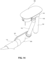
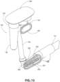
- the bathtub assembly 100 includes a dispenser/waterfall assembly 150 in fluid communication between the circulation system 1 10 and the interior cavity of the inner shell 101 via the at least one dispenser flow opening/waterfall opening 107 formed in the inner shell 101.
- the dispenser/waterfall assembly 150 includes a waterfall assembly, which includes a dispenser tank 152, a waterfall plenum chamber 153, and an outlet housing 157, in fluid communication between the circulation system 110 and the interior cavity of the inner shell 101.
- the outlet housing 157 is connected to an exterior surface of the inner shell 101 at the at least one dispenser flow opening 107.
- the dispenser tank 152, waterfall plenum chamber 153, and the outlet housing 157 are configured to convey at least a portion of the flow liquid created by the circulation system 110 into the interior cavity of the inner shell 101 through the at least one dispenser flow opening/waterfall opening 107.
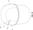
- the waterfall assembly and the at least one dispenser flow opening/waterfall opening 107 are configured to form the at least a portion of the flow of the liquid into a waterfall W as the at least a portion of the flow of the liquid passes through the at least one waterfall opening 107 into the interior cavity of the inner shell 101.
- the dispenser/waterfall assembly 150 also includes a dispenser assembly, which includes a dispenser inlet 151, the dispenser tank 152 and a strainer or basket 159 positioned within the dispenser tank 152.
- the dispenser tank 152 is in fluid communication between the circulation system 110, the waterfall plenum chamber 153, and the outlet housing 157.
- the dispenser tank 152 and strainer/basket 159 are configured to contain a substance therein and to expose the substance to the at least a portion of the flow of the liquid conveyed to the at least one dispenser flow opening 107 such that the substance is introduced into the volume of liquid in the interior cavity of the inner shell 101 via the waterfall W.
- the dispenser/waterfall assembly 150 forms the waterfall W in a non-pressurized manner by forming a plenum or reservoir of liquid above the height of the outlet housing 157 and the at least one dispenser flow opening 107.
- the containment of the liquid within the plenum creates a hydrostatic pressure above the at least one dispenser flow opening 107, which in turn generates the flow of liquid forming the waterfall W.
- the plenum is provided with a maximum liquid height level at a distance above the level of the at least one dispenser flow opening 107.
- the pressure created by the liquid held within the plenum causes liquid to flow out of the at least one waterfall opening 107 to form the waterfall W, which streams laterally from the at least one waterfall opening 107 into the interior cavity of the inner shell 101 and falls to the volume of liquid held within the interior cavity, which has a maximum level defined at a height below the level of the at least one waterfall opening 107.
- the maximum liquid height level of the plenum is defined as approximately 0.5-4 cm, more particularly approximately 1-3 cm, and more particularly approximately 2 cm above the level of the at least one dispenser flow opening 107. It is to be appreciated that the maximum height level, the level of the at least one dispenser flow opening 107, and the maximum level of the volume of liquid within the interior cavity may be set at any relative heights found to be suitable to those having ordinary skill in the art.
- the dispenser/waterfall assembly 150 includes the dispenser tank 152, which includes a bottom inlet connected to the dispenser pipeline 114 to place the dispenser tank 152 in fluid communication with the circulation system 110, as discussed above.
- the dispenser tank 152 has a hollow interior defining a cavity for accommodating the strainer/basket 159 therein and for allowing liquid from the circulation system 110 to fill the dispenser tank 152 and circulate through the strainer/basket 159, thereby dissolving and/or entraining the substance contained in the strainer/basket 159 as the liquid flows through the dispenser tank 152 to the waterfall assembly.
- the strainer/basket 159 has a suitably porous structure to allow the liquid to flow through the strainer/basket 159 while retaining the substance within the dispenser tank 152.
- the strainer/basket 159 includes an external flange 160 at an upper end thereof. The external flange 160 engages the top of the dispenser tank 152 to retain the strainer/basket 159 in the interior of the dispenser tank 152.
- the waterfall plenum chamber 153 is disposed at the top of the dispenser tank 152 and is in fluid communication with the top of the dispenser tank 152.
- the waterfall plenum chamber 153 in combination with the dispenser tank 152, defines the plenum for creating the waterfall W, as discussed above.
- the waterfall plenum chamber 153 includes an overflow drain outlet 154 that is separated from the inlet to the waterfall plenum chamber 153 by a divider wall 161.
- As liquid enters the waterfall plenum chamber 153 from the dispenser tank 152 it fills the waterfall plenum chamber 153 to the height of the divider wall 161, which defines the maximum liquid height level described above. If the liquid level rises above the divider wall 161, it flows over the divider wall 161 into the overflow drain outlet 154.
- the overflow drain outlet 154 is in communication with the suction fitting / dispenser overflow drain 200 via an overflow drain pipe 155 such that overflow liquid from the plenum is returned to the interior cavity of the inner shell 101 via the suction fitting / dispenser overflow drain 200 and the at least one suction opening 106.
- the dispenser tank 152 also includes an outlet tube 156, which places the interior cavity of the dispenser tank 152 in communication with the outlet housing 157.
- the outlet tube 156 is disposed below the top of the dispenser tank 152 such that the top of the dispenser tank 152 and the waterfall plenum chamber 153 define the plenum extending to the height of the divider wall 161 above the outlet tube 156, which creates the liquid pressure causing liquid to flow out of the dispenser tank 152 through the outlet tube 156 and the outlet housing 157 and into the interior cavity of the inner shell 101 via the at least one dispenser flow opening/waterfall opening 107 in the form of the waterfall W.
- the outlet housing 157 may include a flange 158 at one end thereof for fastening the outlet housing 157 to the exterior surface of the inner shell 101 by an adhesive, such as silicon glue, or other suitable fastening mechanism.
- the flange 158 may incorporate a channel extending around the perimeter thereof for accommodating the adhesive.
- the dispenser/waterfall assembly 150 includes a dispenser inlet 151 disposed in the upper rim 104 of the inner shell 101.
- the dispenser inlet 151 provides access to the dispenser tank 152 and the strainer/basket 159 for placing the substance in the strainer/basket 159.
- the control panel 300 is rotatably mounted on the upper rim 104 adjacent to the dispenser inlet 151 so that the control panel 300 may be rotated by the user between a position exposing the dispenser inlet 151, as shown in FIG. 13 , and a position covering the dispenser inlet 151, as shown in FIG. 5 , for example.
- This feature allows for the dispenser inlet 151 to be closed and hidden in the upper rim 104 until the user desires to access the dispenser assembly without the need for a separate cap or closure mechanism, which may become difficult to open, may be lost, and may detract from the overall aesthetic appearance of the bathtub assembly 100.
- the bathtub assembly 100 also includes the suction fitting / dispenser overflow drain 200 connected to the exterior surface of the inner shell 101 at the at least one suction opening 106.
- the suction fitting / dispenser overflow drain 200 may include a flange 201 along one side thereof for fastening the suction fitting / dispenser overflow drain 200 to the exterior surface of the inner shell 101 by an adhesive, such as silicon glue, or other suitable fastening mechanism.
- the flange 201 may incorporate a channel extending around the perimeter thereof for accommodating the adhesive.
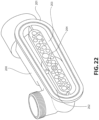
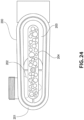
- the suction fitting/overflow drain 200 includes a waterfall overflow portion 202 and a suction outlet portion 203, which are separated from each other but are both in communication with the interior cavity of inner shell 101 via the at least one suction opening 106.
- the waterfall overflow portion 202 receives liquid from the overflow drain outlet 154 via the overflow drain pipe 155 in order to return overflow liquid from the waterfall plenum chamber 153 to the interior cavity of the inner shell 101.
- the suction outlet portion 203 is connected to the suction pipeline 113 in order to convey liquid from the interior cavity of the inner shell 101 back to the pump 111 and the circulation system 110.
- the opening into the suction fitting % dispenser overflow drain 200 may be covered with a suction cover 204 to prevent or limit the occurrence of solid objects entering into the suction fitting % dispenser overflow drain 200 and becoming caught or traveling into the circulation system 110.
- the dispenser/waterfall assembly 150 can be accessed by rotating the control panel 300 to an opening position revealing the dispenser inlet 151.
- the substance or substances are loaded into the strainer/basket 159 positioned within the dispenser tank 152.
- the user may activate a touchscreen control 302 on the control panel 300 to operate the electronic valve 115 to open the dispenser pipeline 114 to flow through the circulation system 110.
- Liquid then flows into the dispenser tank 152 from the bottom and upward through the strainer/basket 159 to dissolve or entrain the substance(s) in the strainer/basket 159.
- the liquid then passes through the at least one directed flow opening/waterfall opening 107 via the outlet housing 157 in the form of the waterfall W.
- the hydrostatic pressure for forming the waterfall W is created by the reservoir of liquid held within the top of the dispenser tank 152 and the waterfall plenum chamber 153. If, during activation of the dispensing functions, the user obstructs the outlet housing 157 or the directed flow jets 120, causing the level of the liquid to rise abnormally within the dispenser tank 152 and the waterfall plenum chamber 153, the liquid will fall over the divider wall 161 in the waterfall plenum chamber 153 and into the overflow drain outlet 154 such that the overflow liquid is returned to the interior cavity of the inner shell 101 through the overflow drain pipe 155 and the suction fitting / dispenser overflow drain 200.
- the dispenser/waterfall assembly 150 is configured to receive any dissolvable or entrainable substance found to be suitable by those having ordinary skill in the art for use in connection with the bathtub assembly 100.
- a dissolvable substance is a substance that, when exposed to the liquid flowing through the dispenser/waterfall assembly 150, will dissolve in the liquid flow and be carried into the interior cavity of the inner shell 101 by the flow of liquid passing through outlet housing 157 and the at least one dispenser flow opening 107.
- An entrainable substance is a substance that, when exposed to the liquid flowing through the dispenser/waterfall assembly 150, will mix and/or blend with and thereby become entrained in the liquid flow and be carried into the interior cavity of the inner shell 101 by the flow of liquid passing through the outlet housing 157 and the at least one dispenser flow opening 107.
- Examples of such dissolvable and/or entrainable substances include bath salts, herbs, aromatherapy, essential oils, plant. and flower extracts, cleaning agents, or combinations of such substances.
- the substances may be provided and loaded into the dispenser tank 152 in the form of powders, granular powders or crystals, liquids, tablets, soluble capsules or pods, etc.
- the substance may be provided in a sealed, pre-measured, disposable pod, cup, or container, and the dispenser tank 152 and/or the strainer/basket 159 may be provided with a piercing or cutting mechanism configured to couple with the disposable pod, cup, or container and pierce or cut the sealed disposable pod, cup, or container and thereby expose the substance within the sealed disposable pod, cup, or container to the flow of liquid through the dispenser/waterfall assembly 150.
- the substances may introduced into the interior cavity of the inner shell 101 of the bathtub assembly 100 in a variety of manners different from the waterfall W discussed above.
- the at least one dispenser flow opening 107 may be disposed in the inner shell 101 below the max bath level such that a waterfall W is not formed by the liquid flow through the dispenser assembly and the outlet housing.
- the dispenser assembly is in communication with one or more directed flow jets, such as the directed flow jets 120 discussed above or similar directed flow jets, such that the directed flow jets also act as the outlet housings for the dispenser assembly and the substance placed in the dispenser assembly is introduced into the volume of liquid in the interior cavity of the inner shell 101 via the directed flow.
- the bathtub assembly 100 includes the control panel 300 rotatably mounted on the upper rim 104 of the inner shell 101.
- the control panel 300 includes a touchscreen interface 301 defining a number of touchscreen controls 302.
- the touchscreen controls 302 may include a control for activating the pump 111 to create the directed flow through the directed flow jets 120 and for controlling the pump 111 to adjust the intensity/speed of the directed flow, a control for operating the valve 115 to open flow through the dispenser/waterfall assembly 150 in order to form the waterfall W and dispense the substances into the volume of the liquid in the interior cavity of the inner shell 101, and a control for activating the lighting features and adjusting the intensity/brightness of the light emitted by the lighting features.
- the touchscreen interface 301 includes three touchscreen controls 302 in the form of touchscreen buttons. It is to be appreciated that more or fewer touchscreen controls 302 may be provided and in any configuration or type as found to be suitable to those having ordinary skill
- the control panel 300 also includes a light guide/diffuser 304 positioned below the touchscreen interface 301.
- the light guide/diffuser 304 transmits light from an LED strip 305, shown in FIG. 29 , positioned within the control panel 300 to the perimeter of the control panel 300, as shown in FIGS. 7 and 26 , in order to create a mood-lighting effect similar to the lighting provided by the RGB LEDs 125 provided on the directed flow jets 120.
- the LED strip 305 and the RGB LEDs 125 are operated by the control panel 300 to transmit light at a uniform or nearly uniform color and intensity.
- the control panel 300 is provided as an extractable unit 303 assembled on the upper rim 104 of the inner shell 101.
- the extractable unit 303 is configured to be removable from the inner shell 101 to allow for repair and replacement of the extractable unit 303 in the event of damage to the control panel 300 and/or upgrading of the control panel 300 or its components/software.
- the extractable unit 303 includes the touchscreen interface 301, light guide/diffuser 304, and a housing 307.
- the housing 307 contains the touchscreen electronics 306, including the controller depending from the touchscreen interface 301 through an opening in the light guide/diffuser 304 and the strip LED 305, which is formed in a circular or arc-shaped structure and positioned to surround or at least partially surround the touchscreen electronics 306 within the opening in the light guide/diffuser 304.
- the touchscreen electronics 306 are configured to control the operations of the components of the bathtub assembly 1 00, including the pump 111, the electronic valve 115, and the lighting features 125, 305.
- Wiring 313 is connected to the touchscreen electronics 306 within the housing 307 and connects the touchscreen electronics 306 with the controlled components of the bathtub assembly 100.
- the touchscreen electronics 306 are configured to be waterproof or water resistant and are capable of operating when exposed to water or other liquids.
- the housing 307 includes a bottom member that seals the interior of the housing 307 and provides a volume for protecting the touchscreen electronics 306 from moisture and contaminants.
- a rotation mechanism 308 is provided in an opening defined in the upper rim 104 of the inner shell 101 that engages the housing 307 to rotatably support the extractable unit 303 on the upper rim 104 and allow the control panel 300 to be rotated by the user between the positions exposing and covering the dispenser inlet 151.
- An O-ring or gasket 309 is provided around the housing 307 for sealing the engagement between the housing 307 and the rotation mechanism 308.
- a lock pin 310 is inserted through an aperture defined in the rotation mechanism to engage a groove or channel defined in the housing 307. The lock pin 310 engages the housing 307 and the rotation mechanism 308 to prevent the extractable unit 303 from being removed directly from the upper rim 104.
- the housing 307 and/or the rotation mechanism 308 may include rotation stops for limiting rotation of the control panel 300 beyond the positions covering and exposing the dispenser inlet 151.
- a method of operating a bathtub assembly 100 includes providing the bathtub assembly 100.
- the bathtub assembly 100 includes a bathtub shell 101 defining an interior cavity configured to contain a volume of liquid, the bathtub shell 101 having at least one dispenser flow opening 107 and a plurality of directed flow openings 105 defined therein; a circulation system 110 in communication with the interior cavity of the bathtub shell 101, the circulation system 110 being configured to create a flow of the liquid to and from the interior cavity of the bathtub shell 101; a plurality of directed flow jets 120 in fluid communication between the circulation system 110 and the interior cavity of the bathtub shell 101, the plurality of directed flow jets 120 being configured to convey at least a first portion of the flow of the liquid through the directed flow openings 105 to create a directed flow of the liquid within the interior cavity of the bathtub shell 101; a housing 157 in fluid communication between the circulation system 110 and the interior cavity of the bathtub shell 101, the housing 157 being connected to the bathtub shell 101 at the at least
- the method further includes filling the interior cavity of the bathtub shell 101 with the volume of liquid; inserting the substance into the dispenser assembly; activating the circulation system 110 to create the flow of the liquid to and from the interior cavity of the bathtub shell 101 through the directed flow jets to form the directed flow of the liquid within the interior cavity of the bathtub shell; and operating the valve 115 to allow the second portion of the flow of the liquid to pass through the dispenser assembly, the housing 157, and the at least one dispenser flow opening 107 to introduce the substance to the volume of liquid in the interior cavity of the bathtub shell 101 via the at least one dispenser flow opening 107.
- the bathtub assembly 100 may further include a control panel 300 configured to be operated to control the circulation system 110 and the valve 115.
- the step of activating the circulation system 1 10 may include actuating a first control 302 on the control panel 300 for controlling the circulation system 110 to create the flow of the liquid to and from the interior cavity, and the step of operating the valve 115 may include actuating a second control 302 on the control panel 300 for controlling the valve 115 to allow the second portion of the flow of the liquid to be directed to the dispenser assembly and the housing 157.
- the control panel 300 may be rotatably connected to an upper rim 104 of the bathtub shell 101.
- the dispenser assembly may include a dispenser inlet 151 disposed in the upper rim 104 of the bathtub shell 101 adjacent to the control panel 300 and configured to provide access for placing the substance in the dispenser assembly; and the step of inserting the substance into the dispenser assembly may include rotating the control panel 300 to a position exposing the dispenser inlet 151, inserting the substances into the dispenser assembly via the dispenser inlet 151, and rotating the control panel 300 to a position covering the dispenser inlet 151.
- the bathtub assembly 1 00 may further include a plurality of lighting features 125, 305, and the control panel 300 is configured to be operated to control the lighting features 125, 305.
- the method may further include actuating a third control 302 on the control panel 300 for controlling the lighting features 125, 305 to operate the lighting features 125, 305 and to adjust a color and intensity of light emitted by the lighting features 125, 305.
- the at least one dispenser flow opening 107 may include a waterfall opening 107
- the bathtub assembly 100 may further include a waterfall plenum chamber 153 in fluid communication with the dispenser assembly and the housing 157.
- the dispenser assembly, the waterfall plenum chamber 153, the housing 157, and the waterfall opening 107 are configured to form the second portion of the flow of the liquid into a waterfall W as the second portion of the flow of the liquid passes through the waterfall opening 107 into the interior cavity of the bathtub shell 101.
Landscapes
- Health & Medical Sciences (AREA)
- Public Health (AREA)
- Epidemiology (AREA)
- Pain & Pain Management (AREA)
- Physical Education & Sports Medicine (AREA)
- Rehabilitation Therapy (AREA)
- Life Sciences & Earth Sciences (AREA)
- Animal Behavior & Ethology (AREA)
- General Health & Medical Sciences (AREA)
- Veterinary Medicine (AREA)
- Bathtubs, Showers, And Their Attachments (AREA)
- Devices For Medical Bathing And Washing (AREA)
Description
- The present application claims priority to
U.S. Provisional Patent Application No. 62/730,267, filed on September 12, 2018 U.S. Utility Patent Application No. 16/563,284, filed on September 6, 2019 - The present invention relates to a bathtub assembly with water circulation features and, in particular, to a bathtub assembly that dispenses a substance into the tub and creates a directed flow of water within the tub.
- Bathtubs incorporating various therapeutic and/or recreational features, such as spa jets for massage and aeration and associated circulation systems, are known in the art, such as from
US 2004168248 A1 , and are becoming increasingly popular in the market. Such massage/aeration jets are typically similar to jets utilized in larger spa tubs and are forceful. Also, the circulation systems utilized to create flow through the jets can be loud. As a result, while these systems offer desirable therapeutic and recreational advantages, the noise and turbulence created by these systems may not be found to be relaxing or soothing by some users and may detract from the overall bathing experience for some users. - Also, the use of therapeutic substances, such as Epsom salts, herb salts, aromatherapy, and essences to provide mental or physical benefits to the user and to contribute to the overall bathing experience is known in the art. Frequently, these substances are simply dispersed or poured by the user into the bath, which results in delayed and uneven dissolution and distribution of the substances. Dispenser assemblies for certain substances are also available, but such dispensers typically involve mechanisms that pour or disperse the substances directly into the bath as the user would.
- The present invention is directed to a bathtub assembly according to claims 1 and 5 and a method of operating a bathtub assembly according to claim 12.
- Subsidiary aspects of the invention are provided in the dependent claims.
- According to an example of the present disclosure, a bathtub assembly is provided that enhances the soothing and relaxation benefits of the bathing experience. The bathtub assembly incorporates a water circulation system and directed flow nozzles for creating a directed flow or stream of water within the bath for soothing hydromassage and relaxation; a dispenser assembly that provides for the addition, dissolution and/or mixing, and distribution of therapeutic substances directly into the bath through use of the water circulation system and via a soothing and relaxing waterfall assembly; and various lighting features for further enhancing the soothing and relaxation benefits of the bathing experience. The bathtub assembly also includes simple controls for operating the water circulation, dispenser, and lighting functions of the bathtub assembly. The controls may be incorporated into a touchscreen panel mounted on the bathtub assembly.
- According to a particular example of the present disclosure, a bathtub assembly is provided. The bathtub assembly includes a bathtub shell defining an interior cavity configured to contain a volume of liquid, the bathtub shell comprising an upper rim at least partially surrounding the interior cavity and having at least one dispenser flow opening defined therein; a circulation system in communication with the interior cavity of the bathtub shell, the circulation system being configured to create a flow of the liquid to and from the interior cavity of the bathtub shell; a housing in fluid communication between the circulation system and the interior cavity of the bathtub shell, the housing being connected to the bathtub shell at the at least one dispenser flow opening and configured to convey at least a portion of the flow of the liquid created by the circulation system into the interior cavity of the bathtub shell through the at least one dispenser flow opening; a dispenser assembly in fluid communication between the circulation system and the housing, the dispenser assembly being configured to contain a substance therein and to expose the substance to the at least a portion of the flow of the liquid conveyed to the at least one dispenser flow opening such that the substance is introduced into the volume of liquid in the interior cavity of the bathtub shell via the at least one dispenser flow opening and the dispenser assembly comprising a dispenser inlet disposed in the upper rim of the bathtub shell configured to provide access for placing the substance in the dispenser assembly; and a control panel configured to be operated to control the circulation system, the control panel being disposed on the upper rim of the bathtub shell adjacent to the dispenser inlet, the control panel being rotatably connected to the upper rim between a position exposing the dispenser inlet and a position covering the dispenser inlet.
- According to another particular example of the present disclosure, a bathtub assembly is provided. The bathtub assembly includes a bathtub shell defining an interior cavity configured to contain a volume of liquid, the bathtub shell having at least one dispenser flow opening and a plurality of directed flow openings defined therein; a circulation system in communication with the interior cavity of the bathtub shell, the circulation system being configured to create a flow of the liquid to and from the interior cavity of the bathtub shell; a plurality of directed flow jets in fluid communication between the circulation system and the interior cavity of the bathtub shell, the plurality of directed flow jets being configured to convey at least a first portion of the flow of the liquid through the directed flow openings to create a directed flow of the liquid within the interior cavity of the bathtub shell; a housing in fluid communication between the circulation system and the interior cavity of the bathtub shell, the housing being connected to the bathtub shell at the at least one dispenser flow opening and configured to convey a second portion of the flow of the liquid created by the circulation system into the interior cavity of the bathtub shell through the at least one dispenser flow opening; a dispenser assembly in fluid communication between the circulation system and the housing, the dispenser assembly being configured to contain a substance therein and to expose the substance to the second portion of the flow of the liquid conveyed to the at least one dispenser flow opening such that the substance is introduced into the volume of liquid in the interior cavity of the bathtub shell via the at least one dispenser flow opening; and a valve positioned in the circulation system, the valve being configured to be operated to allow the second portion of the flow of the liquid created by the circulation system to be directed to the dispenser assembly and the housing.
- According to another particular example of the present disclosure, a method of operating a bathtub assembly is provided. The method includes providing a bathtub assembly. The bathtub assembly includes a bathtub shell defining an interior cavity configured to contain a volume of liquid, the bathtub shell having at least one dispenser flow opening and a plurality of directed flow openings defined therein; a circulation system in communication with the interior cavity of the bathtub shell, the circulation system being configured to create a flow of the liquid to and from the interior cavity of the bathtub shell; a plurality of directed flow jets in fluid communication between the circulation system and the interior cavity of the bathtub shell, the plurality of directed flow jets being configured to convey at least a first portion of the flow of the liquid through the directed flow openings to create a directed flow of the liquid within the interior cavity of the bathtub shell; a housing in fluid communication between the circulation system and the interior cavity of the bathtub shell, the housing being connected to the bathtub shell at the at least one dispenser flow opening and configured to convey a second portion of the flow of the liquid created by the circulation system into the interior cavity of the bathtub shell through the at least one dispenser flow opening; a dispenser assembly in fluid communication between the circulation system and the housing, the dispenser assembly being configured to contain a substance therein and to expose the substance to the second portion of the flow of the liquid conveyed to the at least one dispenser flow opening such that the substance is introduced into the volume of liquid in the interior cavity of the bathtub shell via the at least one dispenser flow opening; and a valve positioned in the circulation system, the valve being configured to be operated to allow the second portion of the flow of the liquid created by the circulation system to be directed to the dispenser assembly and the housing. The method further includes filling the interior cavity of the bathtub shell with the volume of liquid; inserting the substance into the dispenser assembly; activating the circulation system to create the flow of the liquid to and from the interior cavity of the bathtub shell through the directed flow jets to form the directed flow of the liquid within the interior cavity of the bathtub shell; and operating the valve to allow the second portion of the flow of the liquid to pass through the dispenser assembly, the housing, and the at least one dispenser flow opening to introduce the substance to the volume of liquid in the interior cavity of the bathtub shell via the at least one dispenser flow opening.
- These and other features and characteristics of the present invention, as well as the methods of operation and functions of the related elements of structures and the combination of parts and economies of manufacture, will become more apparent upon consideration of the following description and with reference to the accompanying drawings, all of which form a part of this specification, wherein like reference numerals designate corresponding parts in the various figures. It is to be expressly understood, however, that the drawings are for the purpose of illustration and description only and are not intended as a definition of the limits of the invention. As used in the specification and the claims, the singular forms of "a", "an", and "the" include plural referents unless the context clearly dictates otherwise.
-
-
FIG. 1 is a perspective view of a bathtub assembly according to an example of the present disclosure; -
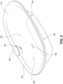
FIG. 2 is a perspective view of an inner shell of the bathtub assembly ofFIG. 1 ; -
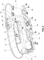
FIG. 3 is a perspective view of the inner shell and interior components of the bathtub assembly ofFIG. 1 ; -
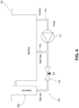
FIG. 4 is a schematic of the liquid circulation system of the bathtub assembly ofFIG. 1 ; -
FIG. 5 is an enlarged perspective view of an upper rim, control panel, and waterfall outlet of the bathtub assembly ofFIG. 1 ; -
FIG. 6 is a perspective view of the bathtub assembly ofFIG. 1 schematically illustrating a directed flow of liquid within the bathtub; - FIG. 7 is a perspective view of the bathtub assembly of
FIG. 1 illustrating lighting features of the bathtub assembly and schematically illustrating the directed flow of liquid within the bathtub; -
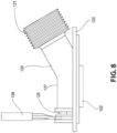
FIG. 8 is a top view of a directed flow jet of the bathtub assembly ofFIG. 1 ; -
FIG. 9 is a front view of the directed flow jet ofFIG. 8 connected to a portion of the inner shell of the bathtub assembly; -
FIG. 10 is a cross-sectional view of the directed flow jet ofFIG. 8 ; -
FIG. 11 is a perspective cross-sectional view of the directed flow jet ofFIG. 8 ; -
FIG. 12 is a perspective view of the bathtub assembly ofFIG. 1 illustrating a waterfall feature of the bathtub assembly; -
FIG. 13 is an enlarged top view of the upper rim and control panel of the bathtub assembly ofFIG. 1 ; -
FIG. 14 is a perspective view of a dispenser and waterfall assembly of the bathtub assembly ofFIG. 1 ; -
FIG. 15 is another perspective view of the dispenser and waterfall assembly ofFIG. 14 ; -
FIG. 16 is a partially exploded view of the dispenser and waterfall assembly ofFIG. 14 ; -
FIG. 17 is an enlarged perspective view of a waterfall plenum chamber of the dispenser and waterfall assembly ofFIG. 14 ; -
FIG. 18 is an enlarged cross-sectional perspective view of the dispenser and waterfall assembly ofFIG. 14 ; -
FIG. 19 is another enlarged cross-sectional perspective view of the dispenser and waterfall assembly ofFIG. 14 ; -
FIG. 20 is another enlarged cross-sectional perspective view of the dispenser and waterfall assembly ofFIG. 14 ; -
FIG. 21 is a perspective view of a suction fitting / dispenser overflow drain of the bathtub assembly ofFIG. 1 connected to the liquid circulation system; -
FIG. 22 is another perspective view of the suction fitting / dispenser overflow drain ofFIG. 21 ; -
FIG. 23 is a cross-sectional perspective view of the suction fitting / dispenser overflow drain ofFIG. 21 ; -
FIG. 24 is a front view of the suction fitting / dispenser overflow drain ofFIG. 21 ; -
FIG. 25 is an enlarged perspective view of a control panel of the bathtub assembly ofFIG. 1 installed on an upper rim of the bathtub; -
FIG. 26 is a perspective view of the control panel ofFIG. 25 with the lighting features activated; -
FIG. 27 is a perspective view of an extractable unit of the control panel ofFIG. 25 ; -
FIG. 28 is another perspective view of the extractable unit ofFIG. 27 with external components removed; and -
FIG. 29 is a cross-sectional perspective view of the control panel ofFIG. 25 . - For purposes of the description hereinafter, the terms "end", "upper", "lower", "right", "left", "vertical", "horizontal", "top", "bottom", "lateral", "longitudinal", and derivatives thereof shall relate to the invention as it is oriented in the drawing figures. However, it is to be understood that the invention may assume various alternative variations and step sequences, except where expressly specified to the contrary. It is also to be understood that the specific devices and processes illustrated in the attached drawings and described in the following specification are simply exemplary embodiments or aspects of the invention. Hence, specific dimensions and other physical characteristics related to the embodiments or aspects disclosed herein are not to be considered as limiting.
- With reference to
FIGS. 1 -7, abathtub assembly 100 is shown according to an example of the present disclosure. Thebathtub assembly 100 includes aninner shell 101 and anouter shell 102. Theinner shell 101 defines an interior cavity of thebathtub assembly 100 for containing a volume of liquid, in particular water, sufficiently large for a user to bathe in while fully or mostly immersed in the water. Theassembly 100 includes adrain 103 in communication with the interior cavity of theinner shell 101 and connected to a drain pipe for draining the volume of liquid from the interior cavity after use of thebathtub assembly 100 is complete. Theouter shell 102 defines the exterior of thebathtub assembly 100. According to an example of the present disclosure, theinner shell 101 and theouter shell 102 of thebathtub assembly 100 are made from a molded acrylic material. It is to be appreciated that theinner shell 101 andouter shell 102 may be made from any material known to be suitable to those having ordinary skill in the art. It is also to be appreciated that theinner shell 101 is disposed within theouter shell 102 and, as such, the exterior surface of theinner shell 101 and any internal components of thebathtub assembly 100 affixed to the exterior surface of theinner shell 101, as will be discussed below, will be hidden from view in thebathtub assembly 100. - It is to be appreciated that the
bathtub assembly 100 may be utilized as an indoor bathtub as frequently found in home bathrooms. Alternatively, thebathtub assembly 100 may be a recreational spa assembly (i.e., "hot tub") configured for outdoor and/or indoor use, a portable tub assembly for use in homes, physical training facilities, and/or medical facilities, and/or a spa assembly configured for use in multiple applications. - As shown in
FIGS. 2 ,6 , and 7, theinner shell 101 also includes anupper rim 104 at least partially surrounding the perimeter of theinner shell 101 and the interior cavity. According to one particular example, theupper rim 104 completely surrounds the perimeter of theinner shell 101 and the interior cavity. A plurality of directedflow openings 105 are formed in theinner shell 101 extending through theinner shell 101 from an exterior surface thereof to a surface of the interior cavity. The directedflow openings 105 provide for the communication of directedflow jets 120, shown inFIG. 3 , with the interior cavity of theinner shell 101. The directedflow openings 105 are defined in the lateral sides of theinner shell 101 approximately midway along the height of theinner shell 101. As shown, there are four spaced directedflow openings 105 that may be provided as spaced sets of directedflow openings 105. At least one dispenser flow opening 107 or waterfall opening is also formed in theinner shell 101 approximately midway along the length of one of the lateral sides of the inner shell and proximate to the top of the interior cavity, i.e., slightly below theupper rim 104. The dispenser flow opening 107 provides for the communication of a dispenser andwaterfall assembly 150, as shown inFIG. 3 , with the interior cavity of theinner shell 101. According to the illustrated example, the dispenser flow opening 107 is positioned directly below acontrol panel 300. At least onesuction opening 106 is also formed in theinner shell 101 directly below thedispenser flow opening 107. Thesuction opening 106 provides for the communication of a suction fitting /dispenser overflow drain 200, as shown inFIG. 3 , with the interior cavity of theinner shell 101. It is to be appreciated that the size and shape of theinner shell 101 and theouter shell 102, as well as the size, shape, positioning, and arrangement of the above-mentionedopenings - With reference to
FIG. 3 , thebathtub assembly 100 may further include asupport frame 108 positioned under theinner shell 101 and within theouter shell 102 for supporting thebathtub assembly 100 on a floor surface and distributing the weight of thebathtub assembly 100, the volume of liquid, and the user along the floor surface. - With reference to
FIGS. 3 and4 , thebathtub assembly 100 includes acirculation system 110 in communication with the interior cavity of theinner shell 101 via the above-mentionedopenings circulation system 110 is configured to create a circulating flow of the liquid to and from the interior cavity of theinner shell 101. In particular, thecirculation system 110 includes apump 111 for creating a pressurized flow of the liquid within a piping system. The piping system includes a directedflow pipeline 112 for conveying the pressurized flow of liquid from thepump 111 to a plurality of directedflow jets 120, asuction pipeline 113 for conveying a return flow of the liquid from the interior cavity of theinner shell 101 to thepump 111 via a suction fitting /dispenser overflow drain 200, and adispenser pipeline 114 for conveying the pressurized flow of liquid from thepump 111 to a dispenser/waterfall assembly 150. According to an example of the present disclosure, thedispenser pipeline 114 is branched from the directedflow pipeline 112, and avalve 115 is provided for selectively controlling the flow of liquid to the dispenser/waterfall assembly 150. According to an example of the present disclosure, thevalve 115 may be an electrically operated and remotely operable valve of any type found to be suitable to those having ordinary skill in the art. - According to an example of the present disclosure, the
pump 111 operates silently or with minimal noise and without air compression, such that the only appreciable noise created by thecirculation system 110 is the sound of flowing liquid moving into and around the interior cavity of theinner shell 101. According to another example of the present disclosure, the circulation system 1 10 also includes a heater (not shown) for heating or maintaining the temperature of the liquid as it is circulated to and from the interior cavity of theinner shell 101. According to an example of the present disclosure, the function of thepump 111 and the function of the heater may be adjusted according to the user's preferences. - With reference to
FIGS. 1-3 and5 -7, thebathtub assembly 100 also includes acontrol panel 300 rotatably mounted on theupper rim 104 of theinner shell 101. As will be discussed further below, thecontrol panel 300 includes a number of touchscreen controls 302, shown inFIGS. 27 and28 , that are operated by the user to control thecirculation system 110 and the lighting features of thebathtub assembly 100, as will be discussed in further detail below. According to an example of the present disclosure, thecontrol panel 300 is connected to theupper rim 104 adjacent to and directly above thedispenser flow opening 107. When activated via thecontrol panel 300, thepump 111 will create a pressurized flow of the liquid through the directedflow pipeline 112 to the directedflow jets 120. Liquid is pulled from the interior cavity and returned to thepump 111 via the suction fitting /dispenser overflow drain 200 and thesuction pipeline 113, such that a closed system of recirculated liquid is formed. As mentioned above, thecirculation system 110 may include an inline heater for heating the recirculated flow of liquid. According to an example of the present disclosure, thepipelines - As shown in
FIGS. 6 and 7, the constant re-circulating flow of liquid into the interior cavity of theinner shell 101 via the directedflow jets 120 and out of the interior cavity of theinner shell 101 via the suction fitting /dispenser overflow drain 200 creates a directional flow of the liquid within the interior cavity. As will be discussed below, the directedflow jets 120 are further configured to angle the flow of liquid into the interior cavity along the sides of theinner shell 101 in a swirling or circulation motion to create a pleasing and relaxing stream of the liquid moving over and around the user. Thus, the directed flow of the liquid through the directedflow jets 120 offers a hydromassage benefit to the user without directly targeting a specific part of the user's body and without relying on powerful, turbulent jets of liquid or air and liquid. The speed/intensity of the directed flow of liquid may be set to the user's preference via a control incorporated in thecontrol panel 300. - As shown in
FIGS. 3-5 ,12 , and 13, thecirculation system 110 also conveys the liquid to the dispenser/waterfall assembly 150 through thedispenser pipeline 114. Flow to the dispenser/waterfall assembly 150 is selectively controlled by thevalve 115, which may be activated or de-activated to permit flow through the dispenser pipeline via a control incorporated in thecontrol panel 300. The dispenser/waterfall assembly 150 provides for the dissolution, mixing, and/or entrainment and the subsequent distribution of substances, such as bath salts, herbs, aromatherapy, cleaning agents, or combinations of such substances, into the interior cavity of theinner shell 101 and for the creation of a flow of liquid carrying the substance or substances into the interior cavity of the inner shell in the form of a soothing, pleasant waterfall W. While thepump 111 is activated to create the directed flow of liquid into the interior cavity, thevalve 115 is operated, via thecontrol panel 300, to open flow through thedispenser pipeline 114 to the dispenser/waterfall assembly 150. The dispenser/waterfall assembly 150 is loaded with the substance by a user such that the flow of liquid into the dispenser/waterfall assembly 150 is mixed with the substance and is then directed into the interior cavity of theinner shell 101 by the dispenser/waterfall assembly 150 in the form of a waterfall W. - With reference to
FIGS. 3 and6-11 , thebathtub assembly 100 includes a plurality of directed flow or "swirl"jets 120 distributed around theinner shell 101 and in fluid communication between the circulation system 1 10 and the interior cavity of theinner shell 101. The directedflow jets 120 convey at least a portion of the flow of the liquid created by thecirculation system 110 into the interior cavity of theinner shell 101 through the plurality of directedflow openings 105 to create the directed flow of liquid within the interior cavity of theinner shell 101. - As shown in
FIGS. 8-11 , each directedflow jet 120 includes aninlet 121 connected to a branch of the directed flow pipeline 112 (shown inFIG. 3 ) and anoutlet 122 that opens into the interior cavity of theinner shell 101. Aflow passage 124 is defined in the directedflow jet 120 between theinlet 121 and theoutlet 122. Aflange 123 surrounds theoutlet 122. Theflange 123 is directly affixed to an exterior surface of theinner shell 101 at at least one of the directedflow openings 105 in order to connect the directedflow jet 120 to theinner shell 101. - The
flange 123 is offset from an end of theoutlet 122, and theoutlet 122 has a shape, such as an oval or elliptical shape, corresponding to the shape of the directed flow opening 105 such that theoutlet 122 extends into the directed flow opening 105 and terminates flush with or substantially flush with the interior surface of theinner shell 101, as shown inFIG. 9 , thus providing for direct fluid communication between theflow passage 124 and the interior cavity of theinner shell 101. Theflow passage 124 extends at an angle A with respect to theflange 123 and the local portion of theinner shell 101 in order to form the directed flow of liquid within the interior cavity discussed above with reference toFIGS. 6 and 7. According to a particular example of the present disclosure, the angle A is approximately 15°-45°, more particularly approximately 25°-35°, and more particularly approximately 30° in order to form a directed flow of liquid at a corresponding angle within the interior cavity along the interior surface of theinner shell 101. It is to be appreciated that the angle A may be any angle found to be suitable to those having ordinary skill in the art for creating the directed flow of the liquid. - According to an example of the present disclosure, the
flange 123 is adhered directly to an exterior surface of theinner shell 101 with a suitable adhesive, such as a silicon glue. Theflange 123 may incorporate a channel extending around the perimeter thereof for holding a reservoir of the adhesive. It is to be appreciated that the directedflow jets 120 may be directly affixed to the exterior surface. - The directed
flow jet 120 also includes anextension 127 protruding therefrom. Theextension 127 supports a lighting device, such as anRGB LED 125. TheRGB LED 125 may be connected to the bathtub assembly's power system and to thecontrol panel 300 viawiring 126. According to an example of the present disclosure, the directedflow jets 120 are fully or partially formed from a transparent or translucent material, such as a transparent acrylic or polymer material, so that the directedflow jets 120 act as light guides for transmitting light from theRGB LED 125 into the interior cavity of theinner shell 101. When activated via thecontrol panel 300, theRGB LEDs 125 provide backlighting to the directed flow jet visible from the interior cavity of theinner shell 101, as shown in FIG. 7, which creates a mood-lighting effect that further enhances the relaxation benefits of the bathing experience for the user. According to another example of the present disclosure, theRGB LEDs 125 can be activated to transmit light in different colors and at different intensities / brightness levels. The color and intensity of the light can be controlled by the user through thecontrol panel 300. It is to be appreciated that the lighting devices associated with the directedflow jets 120 may be of any type found to be suitable to those having ordinary skill in the art. - As discussed above, the directed
flow jets 120 are transparent or translucent to visible light in order to create a light guide to transmit the light emitted by theRGB LEDs 125. TheRGB LEDs 125 may be synchronized with each other and with the lighting features provided with thecontrol panel 300, as will be discussed below. Thecontrol panel 300 may include adedicated touchscreen control 302 for controlling the color and brightness/intensity of all of the lighting features of thebathtub assembly 100. Theflanges 123 of the directedflow jets 120 may be adhered, such as by an adhesive glue, directly to the exterior surface of theinner shell 101, such that theoutlets 122 extend flush with or substantially flush with the interior surface of theinner shell 101 and only a thin oval or elliptical transparent boundary is visible from within the interior cavity. From the perspective of a user within the interior cavity, the directedflow jets 120 may appear as elliptical or oval holes in theinner shell 101, which can be backlit by theRGB LEDs 125. - With reference to
FIGS. 3 and12-24 , thebathtub assembly 100 includes a dispenser/waterfall assembly 150 in fluid communication between the circulation system 1 10 and the interior cavity of theinner shell 101 via the at least one dispenser flow opening/waterfall opening 107 formed in theinner shell 101. The dispenser/waterfall assembly 150 includes a waterfall assembly, which includes adispenser tank 152, awaterfall plenum chamber 153, and anoutlet housing 157, in fluid communication between thecirculation system 110 and the interior cavity of theinner shell 101. Theoutlet housing 157 is connected to an exterior surface of theinner shell 101 at the at least onedispenser flow opening 107. Thedispenser tank 152,waterfall plenum chamber 153, and theoutlet housing 157 are configured to convey at least a portion of the flow liquid created by thecirculation system 110 into the interior cavity of theinner shell 101 through the at least one dispenser flow opening/waterfall opening 107. The waterfall assembly and the at least one dispenser flow opening/waterfall opening 107 are configured to form the at least a portion of the flow of the liquid into a waterfall W as the at least a portion of the flow of the liquid passes through the at least onewaterfall opening 107 into the interior cavity of theinner shell 101. - The dispenser/
waterfall assembly 150 also includes a dispenser assembly, which includes adispenser inlet 151, thedispenser tank 152 and a strainer orbasket 159 positioned within thedispenser tank 152. Thedispenser tank 152 is in fluid communication between thecirculation system 110, thewaterfall plenum chamber 153, and theoutlet housing 157. Thedispenser tank 152 and strainer/basket 159 are configured to contain a substance therein and to expose the substance to the at least a portion of the flow of the liquid conveyed to the at least one dispenser flow opening 107 such that the substance is introduced into the volume of liquid in the interior cavity of theinner shell 101 via the waterfall W. - With reference to
FIG. 12 , the dispenser/waterfall assembly 150 forms the waterfall W in a non-pressurized manner by forming a plenum or reservoir of liquid above the height of theoutlet housing 157 and the at least onedispenser flow opening 107. As can be readily appreciated by one having ordinary skill in the art, the containment of the liquid within the plenum creates a hydrostatic pressure above the at least one dispenser flow opening 107, which in turn generates the flow of liquid forming the waterfall W. In particular, the plenum is provided with a maximum liquid height level at a distance above the level of the at least onedispenser flow opening 107. The pressure created by the liquid held within the plenum causes liquid to flow out of the at least onewaterfall opening 107 to form the waterfall W, which streams laterally from the at least onewaterfall opening 107 into the interior cavity of theinner shell 101 and falls to the volume of liquid held within the interior cavity, which has a maximum level defined at a height below the level of the at least onewaterfall opening 107. According to a particular example of the present disclosure, the maximum liquid height level of the plenum is defined as approximately 0.5-4 cm, more particularly approximately 1-3 cm, and more particularly approximately 2 cm above the level of the at least onedispenser flow opening 107. It is to be appreciated that the maximum height level, the level of the at least one dispenser flow opening 107, and the maximum level of the volume of liquid within the interior cavity may be set at any relative heights found to be suitable to those having ordinary skill in the art. - With reference to
FIGS. 14-20 , the dispenser/waterfall assembly 150 includes thedispenser tank 152, which includes a bottom inlet connected to thedispenser pipeline 114 to place thedispenser tank 152 in fluid communication with thecirculation system 110, as discussed above. Thedispenser tank 152 has a hollow interior defining a cavity for accommodating the strainer/basket 159 therein and for allowing liquid from thecirculation system 110 to fill thedispenser tank 152 and circulate through the strainer/basket 159, thereby dissolving and/or entraining the substance contained in the strainer/basket 159 as the liquid flows through thedispenser tank 152 to the waterfall assembly. The strainer/basket 159 has a suitably porous structure to allow the liquid to flow through the strainer/basket 159 while retaining the substance within thedispenser tank 152. The strainer/basket 159 includes anexternal flange 160 at an upper end thereof. Theexternal flange 160 engages the top of thedispenser tank 152 to retain the strainer/basket 159 in the interior of thedispenser tank 152. - The
waterfall plenum chamber 153 is disposed at the top of thedispenser tank 152 and is in fluid communication with the top of thedispenser tank 152. Thewaterfall plenum chamber 153, in combination with thedispenser tank 152, defines the plenum for creating the waterfall W, as discussed above. Thewaterfall plenum chamber 153 includes anoverflow drain outlet 154 that is separated from the inlet to thewaterfall plenum chamber 153 by adivider wall 161. As liquid enters thewaterfall plenum chamber 153 from thedispenser tank 152, it fills thewaterfall plenum chamber 153 to the height of thedivider wall 161, which defines the maximum liquid height level described above. If the liquid level rises above thedivider wall 161, it flows over thedivider wall 161 into theoverflow drain outlet 154. Theoverflow drain outlet 154 is in communication with the suction fitting /dispenser overflow drain 200 via anoverflow drain pipe 155 such that overflow liquid from the plenum is returned to the interior cavity of theinner shell 101 via the suction fitting /dispenser overflow drain 200 and the at least onesuction opening 106. - The
dispenser tank 152 also includes anoutlet tube 156, which places the interior cavity of thedispenser tank 152 in communication with theoutlet housing 157. Theoutlet tube 156 is disposed below the top of thedispenser tank 152 such that the top of thedispenser tank 152 and thewaterfall plenum chamber 153 define the plenum extending to the height of thedivider wall 161 above theoutlet tube 156, which creates the liquid pressure causing liquid to flow out of thedispenser tank 152 through theoutlet tube 156 and theoutlet housing 157 and into the interior cavity of theinner shell 101 via the at least one dispenser flow opening/waterfall opening 107 in the form of the waterfall W. Theoutlet housing 157 may include aflange 158 at one end thereof for fastening theoutlet housing 157 to the exterior surface of theinner shell 101 by an adhesive, such as silicon glue, or other suitable fastening mechanism. Theflange 158 may incorporate a channel extending around the perimeter thereof for accommodating the adhesive. - As shown in
FIGS. 13 and29 , the dispenser/waterfall assembly 150 includes adispenser inlet 151 disposed in theupper rim 104 of theinner shell 101. Thedispenser inlet 151 provides access to thedispenser tank 152 and the strainer/basket 159 for placing the substance in the strainer/basket 159. Thecontrol panel 300 is rotatably mounted on theupper rim 104 adjacent to thedispenser inlet 151 so that thecontrol panel 300 may be rotated by the user between a position exposing thedispenser inlet 151, as shown inFIG. 13 , and a position covering thedispenser inlet 151, as shown inFIG. 5 , for example. This feature allows for thedispenser inlet 151 to be closed and hidden in theupper rim 104 until the user desires to access the dispenser assembly without the need for a separate cap or closure mechanism, which may become difficult to open, may be lost, and may detract from the overall aesthetic appearance of thebathtub assembly 100. - With reference to
FIGS. 3 ,14 ,15 , and21-24 , thebathtub assembly 100 also includes the suction fitting /dispenser overflow drain 200 connected to the exterior surface of theinner shell 101 at the at least onesuction opening 106. The suction fitting /dispenser overflow drain 200 may include aflange 201 along one side thereof for fastening the suction fitting /dispenser overflow drain 200 to the exterior surface of theinner shell 101 by an adhesive, such as silicon glue, or other suitable fastening mechanism. Theflange 201 may incorporate a channel extending around the perimeter thereof for accommodating the adhesive. The suction fitting/overflow drain 200 includes awaterfall overflow portion 202 and asuction outlet portion 203, which are separated from each other but are both in communication with the interior cavity ofinner shell 101 via the at least onesuction opening 106. Thewaterfall overflow portion 202 receives liquid from theoverflow drain outlet 154 via theoverflow drain pipe 155 in order to return overflow liquid from thewaterfall plenum chamber 153 to the interior cavity of theinner shell 101. Thesuction outlet portion 203 is connected to thesuction pipeline 113 in order to convey liquid from the interior cavity of theinner shell 101 back to thepump 111 and thecirculation system 110. The opening into the suction fitting %dispenser overflow drain 200 may be covered with asuction cover 204 to prevent or limit the occurrence of solid objects entering into the suction fitting %dispenser overflow drain 200 and becoming caught or traveling into thecirculation system 110. - With reference to
FIGS. 3 and12-24 , the dispenser/waterfall assembly 150 can be accessed by rotating thecontrol panel 300 to an opening position revealing thedispenser inlet 151. The substance or substances are loaded into the strainer/basket 159 positioned within thedispenser tank 152. With thepump 111 in operation, the user may activate atouchscreen control 302 on thecontrol panel 300 to operate theelectronic valve 115 to open thedispenser pipeline 114 to flow through thecirculation system 110. Liquid then flows into thedispenser tank 152 from the bottom and upward through the strainer/basket 159 to dissolve or entrain the substance(s) in the strainer/basket 159. The liquid then passes through the at least one directed flow opening/waterfall opening 107 via theoutlet housing 157 in the form of the waterfall W. The hydrostatic pressure for forming the waterfall W is created by the reservoir of liquid held within the top of thedispenser tank 152 and thewaterfall plenum chamber 153. If, during activation of the dispensing functions, the user obstructs theoutlet housing 157 or the directedflow jets 120, causing the level of the liquid to rise abnormally within thedispenser tank 152 and thewaterfall plenum chamber 153, the liquid will fall over thedivider wall 161 in thewaterfall plenum chamber 153 and into theoverflow drain outlet 154 such that the overflow liquid is returned to the interior cavity of theinner shell 101 through theoverflow drain pipe 155 and the suction fitting /dispenser overflow drain 200. - According to an example of the present disclosure, the dispenser/
waterfall assembly 150 is configured to receive any dissolvable or entrainable substance found to be suitable by those having ordinary skill in the art for use in connection with thebathtub assembly 100. A dissolvable substance is a substance that, when exposed to the liquid flowing through the dispenser/waterfall assembly 150, will dissolve in the liquid flow and be carried into the interior cavity of theinner shell 101 by the flow of liquid passing throughoutlet housing 157 and the at least onedispenser flow opening 107. An entrainable substance is a substance that, when exposed to the liquid flowing through the dispenser/waterfall assembly 150, will mix and/or blend with and thereby become entrained in the liquid flow and be carried into the interior cavity of theinner shell 101 by the flow of liquid passing through theoutlet housing 157 and the at least onedispenser flow opening 107. Examples of such dissolvable and/or entrainable substances include bath salts, herbs, aromatherapy, essential oils, plant. and flower extracts, cleaning agents, or combinations of such substances. The substances may be provided and loaded into thedispenser tank 152 in the form of powders, granular powders or crystals, liquids, tablets, soluble capsules or pods, etc. According to an example of the present disclosure, the substance may be provided in a sealed, pre-measured, disposable pod, cup, or container, and thedispenser tank 152 and/or the strainer/basket 159 may be provided with a piercing or cutting mechanism configured to couple with the disposable pod, cup, or container and pierce or cut the sealed disposable pod, cup, or container and thereby expose the substance within the sealed disposable pod, cup, or container to the flow of liquid through the dispenser/waterfall assembly 150. - It is to be appreciated that the substances may introduced into the interior cavity of the
inner shell 101 of thebathtub assembly 100 in a variety of manners different from the waterfall W discussed above. For instance, the at least one dispenser flow opening 107 may be disposed in theinner shell 101 below the max bath level such that a waterfall W is not formed by the liquid flow through the dispenser assembly and the outlet housing. According to one example of the present disclosure, the dispenser assembly is in communication with one or more directed flow jets, such as the directedflow jets 120 discussed above or similar directed flow jets, such that the directed flow jets also act as the outlet housings for the dispenser assembly and the substance placed in the dispenser assembly is introduced into the volume of liquid in the interior cavity of theinner shell 101 via the directed flow. - With reference to
FIGS. 25-29 , thebathtub assembly 100 includes thecontrol panel 300 rotatably mounted on theupper rim 104 of theinner shell 101. Thecontrol panel 300 includes atouchscreen interface 301 defining a number of touchscreen controls 302. As discussed above, according to an example of the present disclosure, the touchscreen controls 302 may include a control for activating thepump 111 to create the directed flow through the directedflow jets 120 and for controlling thepump 111 to adjust the intensity/speed of the directed flow, a control for operating thevalve 115 to open flow through the dispenser/waterfall assembly 150 in order to form the waterfall W and dispense the substances into the volume of the liquid in the interior cavity of theinner shell 101, and a control for activating the lighting features and adjusting the intensity/brightness of the light emitted by the lighting features. According to the illustrated example, thetouchscreen interface 301 includes threetouchscreen controls 302 in the form of touchscreen buttons. It is to be appreciated that more or fewer touchscreen controls 302 may be provided and in any configuration or type as found to be suitable to those having ordinary skill in the art. - The
control panel 300 also includes a light guide/diffuser 304 positioned below thetouchscreen interface 301. The light guide/diffuser 304 transmits light from anLED strip 305, shown inFIG. 29 , positioned within thecontrol panel 300 to the perimeter of thecontrol panel 300, as shown in FIGS. 7 and26 , in order to create a mood-lighting effect similar to the lighting provided by theRGB LEDs 125 provided on the directedflow jets 120. According to an example of the present disclosure, theLED strip 305 and theRGB LEDs 125 are operated by thecontrol panel 300 to transmit light at a uniform or nearly uniform color and intensity. - As shown in
FIGS. 27-29 , thecontrol panel 300 is provided as anextractable unit 303 assembled on theupper rim 104 of theinner shell 101. Theextractable unit 303 is configured to be removable from theinner shell 101 to allow for repair and replacement of theextractable unit 303 in the event of damage to thecontrol panel 300 and/or upgrading of thecontrol panel 300 or its components/software. Theextractable unit 303 includes thetouchscreen interface 301, light guide/diffuser 304, and ahousing 307. Thehousing 307 contains thetouchscreen electronics 306, including the controller depending from thetouchscreen interface 301 through an opening in the light guide/diffuser 304 and thestrip LED 305, which is formed in a circular or arc-shaped structure and positioned to surround or at least partially surround thetouchscreen electronics 306 within the opening in the light guide/diffuser 304. Thetouchscreen electronics 306 are configured to control the operations of the components of the bathtub assembly 1 00, including thepump 111, theelectronic valve 115, and the lighting features 125, 305. Wiring 313 is connected to thetouchscreen electronics 306 within thehousing 307 and connects thetouchscreen electronics 306 with the controlled components of thebathtub assembly 100. According to one example of the present disclosure, thetouchscreen electronics 306 are configured to be waterproof or water resistant and are capable of operating when exposed to water or other liquids. According to another example of the present disclosure, thehousing 307 includes a bottom member that seals the interior of thehousing 307 and provides a volume for protecting thetouchscreen electronics 306 from moisture and contaminants. - A
rotation mechanism 308 is provided in an opening defined in theupper rim 104 of theinner shell 101 that engages thehousing 307 to rotatably support theextractable unit 303 on theupper rim 104 and allow thecontrol panel 300 to be rotated by the user between the positions exposing and covering thedispenser inlet 151. An O-ring orgasket 309 is provided around thehousing 307 for sealing the engagement between thehousing 307 and therotation mechanism 308. Alock pin 310 is inserted through an aperture defined in the rotation mechanism to engage a groove or channel defined in thehousing 307. Thelock pin 310 engages thehousing 307 and therotation mechanism 308 to prevent theextractable unit 303 from being removed directly from theupper rim 104. To remove theextractable unit 303, a technician must first access the interior space between theinner shell 101 and theouter shell 102 and remove thelock pin 310 from the engagement with thehousing 307 and therotation mechanism 308. According to an example of the present disclosure, thehousing 307 and/or therotation mechanism 308 may include rotation stops for limiting rotation of thecontrol panel 300 beyond the positions covering and exposing thedispenser inlet 151. - With reference to
FIGS. 1-29 , according to an example of the present disclosure, a method of operating abathtub assembly 100 is provided. The method includes providing thebathtub assembly 100. The bathtub assembly 100 includes a bathtub shell 101 defining an interior cavity configured to contain a volume of liquid, the bathtub shell 101 having at least one dispenser flow opening 107 and a plurality of directed flow openings 105 defined therein; a circulation system 110 in communication with the interior cavity of the bathtub shell 101, the circulation system 110 being configured to create a flow of the liquid to and from the interior cavity of the bathtub shell 101; a plurality of directed flow jets 120 in fluid communication between the circulation system 110 and the interior cavity of the bathtub shell 101, the plurality of directed flow jets 120 being configured to convey at least a first portion of the flow of the liquid through the directed flow openings 105 to create a directed flow of the liquid within the interior cavity of the bathtub shell 101; a housing 157 in fluid communication between the circulation system 110 and the interior cavity of the bathtub shell 101, the housing 157 being connected to the bathtub shell 101 at the at least one dispenser flow opening 107 and configured to convey a second portion of the flow of the liquid created by the circulation system 110 into the interior cavity of the bathtub shell 101 through the at least one dispenser flow opening 107; a dispenser assembly in fluid communication between the circulation system 110 and the housing 157, the dispenser assembly being configured to contain a substance therein and to expose the substance to the second portion of the flow of the liquid conveyed to the at least one dispenser flow opening 107 such that the substance is introduced into the volume of liquid in the interior cavity of the bathtub shell 101 via the at least one dispenser flow opening 107, and a valve 115 positioned in the circulation system 110, the valve 115 being configured to be operated to allow the second portion of the flow of the liquid created by the circulation system 110 to be directed to the dispenser assembly and the housing 157. The method further includes filling the interior cavity of thebathtub shell 101 with the volume of liquid; inserting the substance into the dispenser assembly; activating thecirculation system 110 to create the flow of the liquid to and from the interior cavity of thebathtub shell 101 through the directed flow jets to form the directed flow of the liquid within the interior cavity of the bathtub shell; and operating thevalve 115 to allow the second portion of the flow of the liquid to pass through the dispenser assembly, thehousing 157, and the at least one dispenser flow opening 107 to introduce the substance to the volume of liquid in the interior cavity of thebathtub shell 101 via the at least onedispenser flow opening 107. - The
bathtub assembly 100 may further include acontrol panel 300 configured to be operated to control thecirculation system 110 and thevalve 115. The step of activating the circulation system 1 10 may include actuating afirst control 302 on thecontrol panel 300 for controlling thecirculation system 110 to create the flow of the liquid to and from the interior cavity, and the step of operating thevalve 115 may include actuating asecond control 302 on thecontrol panel 300 for controlling thevalve 115 to allow the second portion of the flow of the liquid to be directed to the dispenser assembly and thehousing 157. - The
control panel 300 may be rotatably connected to anupper rim 104 of thebathtub shell 101. The dispenser assembly may include adispenser inlet 151 disposed in theupper rim 104 of thebathtub shell 101 adjacent to thecontrol panel 300 and configured to provide access for placing the substance in the dispenser assembly; and the step of inserting the substance into the dispenser assembly may include rotating thecontrol panel 300 to a position exposing thedispenser inlet 151, inserting the substances into the dispenser assembly via thedispenser inlet 151, and rotating thecontrol panel 300 to a position covering thedispenser inlet 151. - The bathtub assembly 1 00 may further include a plurality of lighting features 125, 305, and the
control panel 300 is configured to be operated to control the lighting features 125, 305. The method may further include actuating athird control 302 on thecontrol panel 300 for controlling the lighting features 125, 305 to operate the lighting features 125, 305 and to adjust a color and intensity of light emitted by the lighting features 125, 305. - The at least one dispenser flow opening 107 may include a
waterfall opening 107, and thebathtub assembly 100 may further include awaterfall plenum chamber 153 in fluid communication with the dispenser assembly and thehousing 157. The dispenser assembly, thewaterfall plenum chamber 153, thehousing 157, and thewaterfall opening 107 are configured to form the second portion of the flow of the liquid into a waterfall W as the second portion of the flow of the liquid passes through thewaterfall opening 107 into the interior cavity of thebathtub shell 101. - It is to be understood that the invention may assume various alternative variations and step sequences, except where expressly specified to the contrary. It is also to be understood that the specific devices and processes illustrated in the attached drawings, and described in the specification, are simply exemplary embodiments or aspects of the invention. Although the invention has been described in detail for the purpose of illustration based on what is currently considered to be the most practical and preferred embodiments or aspects, it is to be understood that such detail is solely for that purpose and that the invention is not limited to the disclosed embodiments or aspects. The scope of the present invention is defined by the appended claims.
Claims (16)
- A bathtub assembly (100) comprising:a bathtub shell (101) defining an interior cavity configured to contain a volume of liquid, the bathtub shell (101) comprising an upper rim (104) at least partially surrounding the interior cavity and having at least one dispenser flow opening (107) defined therein;a circulation system (110) in communication with the interior cavity of the bathtub shell (101), the circulation system (110) being configured to create a flow of the liquid to and from the interior cavity of the bathtub shell (101);a housing (157) in fluid communication between the circulation system (110) and the interior cavity of the bathtub shell (101), the housing (157) being connected to the bathtub shell (101) at the at least one dispenser flow opening (107) and configured to convey at least a portion of the flow of the liquid created by the circulation system (110) into the interior cavity of the bathtub shell (101) through the at least one dispenser flow opening (107);a dispenser assembly (150) in fluid communication between the circulation system (110) and the housing (157), the dispenser assembly (150) being configured to contain a substance therein and to expose the substance to the at least a portion of the flow of the liquid conveyed to the at least one dispenser flow opening (107) such that the substance is introduced into the volume of liquid in the interior cavity of the bathtub shell (101) via the at least one dispenser flow opening (107) and the dispenser assembly (150) comprising a dispenser inlet (151) disposed in the upper rim (104) of the bathtub shell (101) configured to provide access for placing the substance in the dispenser assembly (150); anda control panel (300) configured to be operated to control the circulation system (110),the control panel (300) being disposed on the upper rim (104) of the bathtub shell (101) adjacent to the dispenser inlet (151), the control panel (300) being rotatably connected to the upper rim (104) between a position exposing the dispenser inlet (151) and a position covering the dispenser inlet (151).
- The bathtub assembly according to claim 1, wherein the at least one dispenser flow opening (107) comprises a waterfall opening (107) and the bathtub assembly (100) further comprises a waterfall plenum chamber (153) in fluid communication with the dispenser assembly (150) and the housing (157), and
wherein the dispenser assembly (150), waterfall plenum chamber (153), the housing (157), and the waterfall opening (107) are configured to form the at least a portion of the flow of the liquid into a waterfall (W) as the at least a portion of the flow of the liquid passes through the waterfall opening (107) into the interior cavity of the bathtub shell (101). - The bathtub assembly according to claim 1 or 2, wherein the bathtub shell (101) has a plurality of directed flow openings (105) defined therein, and
wherein the bathtub assembly (100) further comprises a plurality of directed flow jets (120) in fluid communication between the circulation system (110) and the interior cavity of the bathtub shell (101), the plurality of directed flow jets (120) being configured to convey at least another portion of the flow of the liquid created by the circulation system (110) into the interior cavity of the bathtub shell (101) through the plurality of directed flow openings (105) to create a directed flow of the liquid within the interior cavity of the bathtub shell (101), each of the plurality of directed flow jets (120) comprising a flange (123) directly affixed to an exterior surface bathtub shell (101) at at least one of the plurality of directed flow openings (105) in the bathtub shell (101). - The bathtub assembly according to any one of claims 1 to 3, further comprising a valve (115) positioned in the circulation system (110), the valve (115) being configured to be operated to allow the at least a portion of the flow of the liquid created by the circulation system (110) to be directed to the dispenser assembly (150) and the housing (157) and/or further comprising a plurality of light features (125,305), the control panel (300) being configured to operate the lighting features (125,305).
- A bathtub assembly (100), comprising:a bathtub shell (101) defining an interior cavity configured to contain a volume of liquid, the bathtub shell (101) having at least one dispenser flow opening (107) and a plurality of directed flow openings (105) defined therein;a circulation system (110) in communication with the interior cavity of the bathtub shell (101), the circulation system (110) being configured to create a flow of the liquid to and from the interior cavity of the bathtub shell (101);a plurality of directed flow jets (120) in fluid communication between the circulation system (110) and the interior cavity of the bathtub shell (101), the plurality of directed flow jets (120) being configured to convey at least a first portion of the flow of the liquid through the directed flow openings (105) to create a directed flow of the liquid within the interior cavity of the bathtub shell (101);a housing (157) in fluid communication between the circulation system (110) and the interior cavity of the bathtub shell (101), the housing (157) being connected to the bathtub shell (101) at the at least one dispenser flow opening (107) and configured to convey a second portion of the flow of the liquid created by the circulation system (110) into the interior cavity of the bathtub shell (101) through the at least one dispenser flow opening (107);a dispenser assembly (150) in fluid communication between the circulation system (110) and the housing (157), the dispenser assembly (150) being configured to contain a substance therein and to expose the substance to the second portion of the flow of the liquid conveyed to the at least one dispenser flow opening (107) such that the substance is introduced into the volume of liquid in the interior cavity of the bathtub shell (101) via the at least one dispenser flow opening (107); anda valve (115) positioned in the circulation system (110), the valve (115) being configured to be operated to allow the second portion of the flow of the liquid created by the circulation system (110) to be directed to the dispenser assembly (150) and the housing (157).
- The bathtub assembly according to claim 5, wherein the at least one dispenser flow opening (107) comprises a waterfall opening (107) and the bathtub assembly (100) further comprises a waterfall plenum chamber (153) in fluid communication with the dispenser assembly (150) and the housing (157), and
wherein the dispenser assembly (150), the waterfall plenum chamber (153), the housing (157), and the waterfall opening (107) are configured to form the second portion of the flow of the liquid into a waterfall (W) as the second portion of the flow of the liquid passes through the waterfall opening (107) into the interior cavity of the bathtub shell (101). - The bathtub assembly according to claim 5 or 6, further comprising a control panel (300) configured to be operated to control the circulation system (110) and the valve (115), the control panel (300) being rotatably connected to an upper rim (104) of the bathtub shell (101),wherein the dispenser assembly (150) comprises a dispenser inlet (151) disposed in the upper rim (104) of the bathtub shell (101) adjacent to the control panel (300) and configured to provide access for placing the substance in the dispenser assembly (150), andwherein the control panel (300) is rotatable on the upper rim (104) between a position exposing the dispenser inlet (151) and a position covering the dispenser inlet (151).
- The bathtub assembly according to claim 7, further comprising a plurality of lighting features (125,305), wherein the control panel (300) is configured to be operated to activate the lighting features (125,305) and to adjust a color and intensity of light emitted by the lighting features (125,305) and, preferably, wherein the lighting features (125,305) comprise a plurality of light-emitting diodes (125) disposed on the plurality of directed flow jets (120) and at least one light-emitting diode (305) disposed on the control panel (300).
- The bathtub assembly according to claim 7 or 8, wherein the control panel (300) is provided as an extractable unit (303) removably assembled on the bathtub shell (101).
- The bathtub assembly according to any one of claims 5 to 9, wherein each of the plurality of directed flow jets (120) comprises a flange (123) directly affixed to an exterior surface bathtub shell (101) at at least one of the plurality of directed flow openings (105) in the bathtub shell (101) and, preferably, wherein each of the plurality of directed flow jets (120) further comprises an outlet (122) disposed in a respective one of the plurality of directed flow openings (105) and extending flush with an interior surface of the bathtub shell (101).
- The bathtub assembly according to any one of claims 5 to 13, wherein the plurality of directed flow jets (120) are configured to direct the directed flow of the liquid within the interior cavity to form a swirling or circulating motion of the liquid within the interior cavity and/or wherein the dispenser assembly (150) comprises a porous holder (159) configured to contain the substance therein.
- A method of operating a bathtub assembly (100), comprising:
providing the bathtub assembly (100), the bathtub assembly (100) comprising:a bathtub shell (101) defining an interior cavity configured to contain a volume of liquid, the bathtub shell (101) having at least one dispenser flow opening (107) and a plurality of directed flow openings (105) defined therein;a circulation system (110) in communication with the interior cavity of the bathtub shell (101), the circulation system (110) being configured to create a flow of the liquid to and from the interior cavity of the bathtub shell (101);a plurality of directed flow jets (120) in fluid communication between the circulation system (110) and the interior cavity of the bathtub shell (101), the plurality of directed flow jets (120) being configured to convey at least a first portion of the flow of the liquid through the directed flow openings (105) to create a directed flow of the liquid within the interior cavity of the bathtub shell (101);a housing (157) in fluid communication between the circulation system (110) and the interior cavity of the bathtub shell (101), the housing (157) being connected to the bathtub shell (101) at the at least one dispenser flow opening (107) and configured to convey a second portion of the flow of the liquid created by the circulation system (110) into the interior cavity of the bathtub shell (101) through the at least one dispenser flow opening (107);a dispenser assembly (150) in fluid communication between the circulation system (110) and the housing (157), the dispenser assembly (150) being configured to contain a substance therein and to expose the substance to the second portion of the flow of the liquid conveyed to the at least one dispenser flow opening (107) such that the substance is introduced into the volume of liquid in the interior cavity of the bathtub shell (101) via the at least one dispenser flow opening (107); anda valve (115) positioned in the circulation system (110), the valve (115) being configured to be operated to allow the second portion of the flow of the liquid created by the circulation system (110) to be directed to the dispenser assembly (150) and the housing (157);filling the interior cavity of the bathtub shell (101) with the volume of liquid;inserting the substance into the dispenser assembly (150);activating the circulation system (110) to create the flow of the liquid to and from the interior cavity of the bathtub shell (101) through the directed flow jets (120) to form the directed flow of the liquid within the interior cavity of the bathtub shell (101); andoperating the valve (115) to allow the second portion of the flow of the liquid to pass through the dispenser assembly (150), the housing (157), and the at least one dispenser flow opening (107) to introduce the substance to the volume of liquid in the interior cavity of the bathtub shell (101) via the at least one dispenser flow opening (107). - The method according to claim 12, wherein the bathtub assembly (100) further comprises a control panel (300) configured to be operated to control the circulation system (110) and the valve (115),wherein the step of activating the circulation system (110) comprises actuating a first control (302) on the control panel (300) for controlling the circulation system (110) to create the flow of the liquid to and from the interior cavity, andwherein the step of operating the valve (115) comprises actuating a second control (302) on the control panel (300) for controlling the valve (115) to allow the second portion of the flow of the liquid to be directed to the dispenser assembly (150) and the housing (157).
- The method according to claim 13, wherein the control panel (300) is rotatably connected to an upper rim (104) of the bathtub shell (101),wherein the dispenser assembly (150) comprises a dispenser inlet (151) disposed in the upper rim (104) of the bathtub shell (101) adjacent to the control panel (300) and configured to provide access for placing the substance in the dispenser assembly (150), andwherein the step of inserting the substance into the dispenser assembly (150) comprises rotating the control panel (300) to a position exposing the dispenser inlet (151), inserting the substances into the dispenser assembly (150) via the dispenser inlet (151), and rotating the control panel (300) to a position covering the dispenser inlet (151).
- The method according to claim 13 or 14, wherein the bathtub assembly (100) further comprises a plurality of lighting features (125,305) and the control panel (300) is configured to be operated to control the lighting features (125,305), and
wherein the method further comprises actuating a third control (302) on the control panel (300) for controlling the lighting features (125,305) to operate the lighting features (125,305) and to adjust a color and intensity of light emitted by the lighting features (125,305). - The method according to any one of claims 12 to 15, wherein the at least one dispenser flow opening (107) comprises a waterfall opening (107) and the bathtub assembly (100) further comprises a waterfall plenum chamber (153) in fluid communication with the dispenser assembly (150) and the housing (157), and wherein the dispenser assembly (150), the waterfall plenum chamber (153), the housing (157), and the waterfall opening (107) are configured to form the second portion of the flow of the liquid into a waterfall (W) as the second portion of the flow of the liquid passes through the waterfall opening (107) into the interior cavity of the bathtub shell (101).
Applications Claiming Priority (3)
| Application Number | Priority Date | Filing Date | Title |
|---|---|---|---|
| US201862730267P | 2018-09-12 | 2018-09-12 | |
| US16/563,284 US10993875B2 (en) | 2018-09-12 | 2019-09-06 | Tub with swirl ports and dispenser |
| PCT/US2019/050376 WO2020055842A1 (en) | 2018-09-12 | 2019-09-10 | Tub with swirl ports and dispenser |
Publications (3)
| Publication Number | Publication Date |
|---|---|
| EP3849493A1 EP3849493A1 (en) | 2021-07-21 |
| EP3849493A4 EP3849493A4 (en) | 2022-10-12 |
| EP3849493B1 true EP3849493B1 (en) | 2024-06-26 |
Family
ID=69721084
Family Applications (1)
| Application Number | Title | Priority Date | Filing Date |
|---|---|---|---|
| EP19859837.7A Active EP3849493B1 (en) | 2018-09-12 | 2019-09-10 | Tub with swirl ports and dispenser |
Country Status (5)
| Country | Link |
|---|---|
| US (1) | US10993875B2 (en) |
| EP (1) | EP3849493B1 (en) |
| BR (1) | BR112021004298A2 (en) |
| CA (1) | CA3109656A1 (en) |
| WO (1) | WO2020055842A1 (en) |
Families Citing this family (9)
| Publication number | Priority date | Publication date | Assignee | Title |
|---|---|---|---|---|
| USD892987S1 (en) * | 2018-09-12 | 2020-08-11 | Jacuzzi Inc. | Bathtub |
| USD948002S1 (en) * | 2019-06-28 | 2022-04-05 | Wet Manufacturing Inc. | Bathtub |
| USD943068S1 (en) * | 2019-10-29 | 2022-02-08 | As America, Inc. | Bathtub |
| US12137848B2 (en) * | 2020-10-31 | 2024-11-12 | Balboa Water Group, Llc | Bathing installation user interface panel with large active display area |
| US11531369B2 (en) * | 2020-10-31 | 2022-12-20 | Balboa Water Group, Llc | Bathing installation user interface panel with large active display area |
| USD963815S1 (en) * | 2021-02-24 | 2022-09-13 | M. Arthur Gensler, Jr. & Associates, Inc. | Tub |
| US12029358B2 (en) | 2021-07-09 | 2024-07-09 | Kohler Co. | Bath with hot and cold water zones |
| USD1057112S1 (en) * | 2022-09-06 | 2025-01-07 | Hansgrohe Se | Bath tub |
| US20240099518A1 (en) * | 2022-09-28 | 2024-03-28 | Conair Llc | Cordless immersible bath jet apparatus |
Family Cites Families (29)
| Publication number | Priority date | Publication date | Assignee | Title |
|---|---|---|---|---|
| US3967323A (en) | 1974-12-31 | 1976-07-06 | Serio Jeannette H | Therapeutic constant flow bath |
| FR2478702A1 (en) | 1980-03-24 | 1981-09-25 | Munne Georges | Spillway for water supply to e.g. domestic bath - may have U=section made in marble cantilevering from box receiving feed from mixer taps |
| US4514868A (en) | 1983-04-27 | 1985-05-07 | Visinand Jean Claude | Bathtub |
| US7875173B1 (en) | 1997-11-21 | 2011-01-25 | Barnes Ronald L | Ozone generator retrofit apparatus for jetted tubs, spas, and other water circulation facilities |
| US6405387B1 (en) | 2000-03-08 | 2002-06-18 | Ronald L. Barnes | Sanitized jetted bathing facility |
| US6723233B1 (en) | 1999-09-10 | 2004-04-20 | Ronald L. Barnes | Ozone generator retrofit apparatus for jetted tubs and spas |
| US6328900B1 (en) | 1999-06-25 | 2001-12-11 | Joseph A. King | Kit and method for converting water circulation system to water circulation and purification system |
| TW418686U (en) | 2000-05-08 | 2001-01-11 | Tzeng Fu Ching | Device for generating artificial hot spring |
| CA2359921A1 (en) | 2000-10-25 | 2002-04-25 | Marquis Corp. | Alcove whirlpool seat spa system |
| BR0006494A (en) | 2000-12-14 | 2002-07-30 | House Incorporadora Ltda I | Automated control system of the parameters involved in the preparation of an immersion bath |
| USD473634S1 (en) | 2001-03-23 | 2003-04-22 | Hoesch Metall + Kunststoffwerk Gmbh & Co. | Bathtub |
| CN101349629B (en) | 2001-08-28 | 2012-11-14 | 三菱丽阳株式会社 | Dissolved gas liquid manufacturing device |
| US6760931B1 (en) | 2002-08-02 | 2004-07-13 | Roy W. Mattson, Jr. | Non-electric sanitation water vessel system |
| US20060002105A1 (en) | 2004-07-02 | 2006-01-05 | B&S Plastics, Inc. Dba Waterway Plastics | LED-illuminated spa jet |
| US7818826B2 (en) | 2005-04-13 | 2010-10-26 | B & S Plastics, Inc. | Laminar flow jet for pools and spas |
| US9248075B2 (en) | 2006-04-19 | 2016-02-02 | Michael Spencer | Laminar jet and hydrotherapy bath system |
| SG156536A1 (en) | 2008-04-08 | 2009-11-26 | Tjia Ng Ghee | An apparatus and method for facilitating mixing of a fluid |
| US20090271921A1 (en) | 2008-04-10 | 2009-11-05 | Castellote Miguel A | User-system interface for tubs |
| US20100187326A1 (en) | 2009-01-23 | 2010-07-29 | Jacuzzi Inc. | Waterfall Unit |
| US9069201B2 (en) | 2010-03-19 | 2015-06-30 | Balboa Wter Group, Inc. | Waterproof user interface display panels |
| US20120192347A1 (en) | 2011-01-31 | 2012-08-02 | Campbell Graham J | Lighted Jets for Bathing Installations |
| ITRM20110143U1 (en) | 2011-09-19 | 2013-03-20 | Gruppo Tre S S P A | WHIRLPOOL BATHTUB. |
| US8847913B2 (en) | 2012-04-04 | 2014-09-30 | Kohler Co. | User interface device for a bath or shower |
| US9259374B2 (en) | 2012-04-24 | 2016-02-16 | C.G. Air Systèmes Inc. | Water massage system for tubs |
| US20140157512A1 (en) | 2012-05-15 | 2014-06-12 | Brian Yanity | Hydro-Therapeutic Jet Massage Device |
| US20140259358A1 (en) | 2013-03-15 | 2014-09-18 | Custom Molded Products, Inc. | Bath with flowing water |
| CA151667S (en) | 2013-06-13 | 2014-03-10 | Wetstyle | Bathtub |
| JP6535438B2 (en) | 2014-05-30 | 2019-06-26 | 株式会社Lixil | Water discharge device and bathtub device |
| US20170017315A1 (en) | 2015-07-14 | 2017-01-19 | Gecko Alliance Group Inc. | Topside control panel for bathing unit system |
-
2019
- 2019-09-06 US US16/563,284 patent/US10993875B2/en active Active
- 2019-09-10 EP EP19859837.7A patent/EP3849493B1/en active Active
- 2019-09-10 CA CA3109656A patent/CA3109656A1/en active Pending
- 2019-09-10 WO PCT/US2019/050376 patent/WO2020055842A1/en not_active Ceased
- 2019-09-10 BR BR112021004298-9A patent/BR112021004298A2/en not_active Application Discontinuation
Also Published As
| Publication number | Publication date |
|---|---|
| CA3109656A1 (en) | 2020-03-19 |
| EP3849493A4 (en) | 2022-10-12 |
| WO2020055842A1 (en) | 2020-03-19 |
| US20200078263A1 (en) | 2020-03-12 |
| US10993875B2 (en) | 2021-05-04 |
| BR112021004298A2 (en) | 2021-05-25 |
| EP3849493A1 (en) | 2021-07-21 |
Similar Documents
| Publication | Publication Date | Title |
|---|---|---|
| US10993875B2 (en) | Tub with swirl ports and dispenser | |
| US6623511B1 (en) | Chromatherapy shower system | |
| AU2001272025B8 (en) | Overflowing soaker bath tub | |
| CA2689799C (en) | Microbubble therapy method and generating apparatus | |
| CA2689797C (en) | Microbubble therapy method and generating apparatus | |
| CA2747165C (en) | Liquid aroma injector | |
| CA2689800C (en) | Microbubble therapy method and generating apparatus | |
| AU2001272025A1 (en) | Overflowing soaker bath tub | |
| US9469978B2 (en) | Exposed shower system | |
| CA2689802C (en) | Microbubble therapy method and generating apparatus | |
| CN105595883B (en) | The bathtub of circulating water flushing | |
| EP2403469B1 (en) | Combination bathtub and spa | |
| US20090218411A1 (en) | Water sheet showerhead | |
| US10426298B2 (en) | Capped rim system for a bathtub | |
| US10792628B2 (en) | Enhanced micro bubble device, system and methods related thereto | |
| HK40058388A (en) | Tub with swirl ports and dispenser | |
| HK40058388B (en) | Tub with swirl ports and dispenser | |
| US20060042689A1 (en) | Skimmer/waterfall with backlight | |
| US20050217016A1 (en) | Aromatherapy/chromotherapeutic system for tubs and method | |
| US8266738B2 (en) | Aromatherapy system for tubs | |
| CN120018834A (en) | Cordless immersion shower jet | |
| EP2452666B1 (en) | Cabin for wellbeing treatments using steam | |
| EP3936017B1 (en) | Bathtub | |
| KR200433009Y1 (en) | Dog bath device using micro bubbles | |
| US7434277B1 (en) | Fluid flow system |
Legal Events
| Date | Code | Title | Description |
|---|---|---|---|
| STAA | Information on the status of an ep patent application or granted ep patent |
Free format text: STATUS: THE INTERNATIONAL PUBLICATION HAS BEEN MADE |
|
| PUAI | Public reference made under article 153(3) epc to a published international application that has entered the european phase |
Free format text: ORIGINAL CODE: 0009012 |
|
| STAA | Information on the status of an ep patent application or granted ep patent |
Free format text: STATUS: REQUEST FOR EXAMINATION WAS MADE |
|
| 17P | Request for examination filed |
Effective date: 20210401 |
|
| AK | Designated contracting states |
Kind code of ref document: A1 Designated state(s): AL AT BE BG CH CY CZ DE DK EE ES FI FR GB GR HR HU IE IS IT LI LT LU LV MC MK MT NL NO PL PT RO RS SE SI SK SM TR |
|
| DAV | Request for validation of the european patent (deleted) | ||
| DAX | Request for extension of the european patent (deleted) | ||
| REG | Reference to a national code |
Ref country code: HK Ref legal event code: DE Ref document number: 40058388 Country of ref document: HK |
|
| A4 | Supplementary search report drawn up and despatched |
Effective date: 20220912 |
|
| RIC1 | Information provided on ipc code assigned before grant |
Ipc: A61H 33/04 20060101ALI20220906BHEP Ipc: A47K 3/00 20060101ALI20220906BHEP Ipc: A61H 33/00 20060101AFI20220906BHEP |
|
| GRAJ | Information related to disapproval of communication of intention to grant by the applicant or resumption of examination proceedings by the epo deleted |
Free format text: ORIGINAL CODE: EPIDOSDIGR1 |
|
| GRAP | Despatch of communication of intention to grant a patent |
Free format text: ORIGINAL CODE: EPIDOSNIGR1 |
|
| GRAJ | Information related to disapproval of communication of intention to grant by the applicant or resumption of examination proceedings by the epo deleted |
Free format text: ORIGINAL CODE: EPIDOSDIGR1 |
|
| STAA | Information on the status of an ep patent application or granted ep patent |
Free format text: STATUS: GRANT OF PATENT IS INTENDED |
|
| GRAP | Despatch of communication of intention to grant a patent |
Free format text: ORIGINAL CODE: EPIDOSNIGR1 |
|
| INTG | Intention to grant announced |
Effective date: 20230823 |
|
| GRAS | Grant fee paid |
Free format text: ORIGINAL CODE: EPIDOSNIGR3 |
|
| STAA | Information on the status of an ep patent application or granted ep patent |
Free format text: STATUS: REQUEST FOR EXAMINATION WAS MADE |
|
| GRAJ | Information related to disapproval of communication of intention to grant by the applicant or resumption of examination proceedings by the epo deleted |
Free format text: ORIGINAL CODE: EPIDOSDIGR1 |
|
| GRAL | Information related to payment of fee for publishing/printing deleted |
Free format text: ORIGINAL CODE: EPIDOSDIGR3 |
|
| GRAP | Despatch of communication of intention to grant a patent |
Free format text: ORIGINAL CODE: EPIDOSNIGR1 |
|
| STAA | Information on the status of an ep patent application or granted ep patent |
Free format text: STATUS: GRANT OF PATENT IS INTENDED |
|
| INTC | Intention to grant announced (deleted) | ||
| INTG | Intention to grant announced |
Effective date: 20240119 |
|
| GRAA | (expected) grant |
Free format text: ORIGINAL CODE: 0009210 |
|
| STAA | Information on the status of an ep patent application or granted ep patent |
Free format text: STATUS: THE PATENT HAS BEEN GRANTED |
|
| AK | Designated contracting states |
Kind code of ref document: B1 Designated state(s): AL AT BE BG CH CY CZ DE DK EE ES FI FR GB GR HR HU IE IS IT LI LT LU LV MC MK MT NL NO PL PT RO RS SE SI SK SM TR |
|
| REG | Reference to a national code |
Ref country code: GB Ref legal event code: FG4D |
|
| REG | Reference to a national code |
Ref country code: CH Ref legal event code: EP |
|
| REG | Reference to a national code |
Ref country code: DE Ref legal event code: R096 Ref document number: 602019054361 Country of ref document: DE |
|
| PG25 | Lapsed in a contracting state [announced via postgrant information from national office to epo] |
Ref country code: BG Free format text: LAPSE BECAUSE OF FAILURE TO SUBMIT A TRANSLATION OF THE DESCRIPTION OR TO PAY THE FEE WITHIN THE PRESCRIBED TIME-LIMIT Effective date: 20240626 |
|
| PG25 | Lapsed in a contracting state [announced via postgrant information from national office to epo] |
Ref country code: FI Free format text: LAPSE BECAUSE OF FAILURE TO SUBMIT A TRANSLATION OF THE DESCRIPTION OR TO PAY THE FEE WITHIN THE PRESCRIBED TIME-LIMIT Effective date: 20240626 Ref country code: HR Free format text: LAPSE BECAUSE OF FAILURE TO SUBMIT A TRANSLATION OF THE DESCRIPTION OR TO PAY THE FEE WITHIN THE PRESCRIBED TIME-LIMIT Effective date: 20240626 |
|
| PGFP | Annual fee paid to national office [announced via postgrant information from national office to epo] |
Ref country code: DE Payment date: 20240924 Year of fee payment: 6 |
|
| REG | Reference to a national code |
Ref country code: LT Ref legal event code: MG9D |
|
| PG25 | Lapsed in a contracting state [announced via postgrant information from national office to epo] |
Ref country code: GR Free format text: LAPSE BECAUSE OF FAILURE TO SUBMIT A TRANSLATION OF THE DESCRIPTION OR TO PAY THE FEE WITHIN THE PRESCRIBED TIME-LIMIT Effective date: 20240927 |
|
| PG25 | Lapsed in a contracting state [announced via postgrant information from national office to epo] |
Ref country code: LV Free format text: LAPSE BECAUSE OF FAILURE TO SUBMIT A TRANSLATION OF THE DESCRIPTION OR TO PAY THE FEE WITHIN THE PRESCRIBED TIME-LIMIT Effective date: 20240626 |
|
| REG | Reference to a national code |
Ref country code: NL Ref legal event code: MP Effective date: 20240626 |
|
| PG25 | Lapsed in a contracting state [announced via postgrant information from national office to epo] |
Ref country code: NO Free format text: LAPSE BECAUSE OF FAILURE TO SUBMIT A TRANSLATION OF THE DESCRIPTION OR TO PAY THE FEE WITHIN THE PRESCRIBED TIME-LIMIT Effective date: 20240926 Ref country code: LV Free format text: LAPSE BECAUSE OF FAILURE TO SUBMIT A TRANSLATION OF THE DESCRIPTION OR TO PAY THE FEE WITHIN THE PRESCRIBED TIME-LIMIT Effective date: 20240626 Ref country code: HR Free format text: LAPSE BECAUSE OF FAILURE TO SUBMIT A TRANSLATION OF THE DESCRIPTION OR TO PAY THE FEE WITHIN THE PRESCRIBED TIME-LIMIT Effective date: 20240626 Ref country code: GR Free format text: LAPSE BECAUSE OF FAILURE TO SUBMIT A TRANSLATION OF THE DESCRIPTION OR TO PAY THE FEE WITHIN THE PRESCRIBED TIME-LIMIT Effective date: 20240927 Ref country code: FI Free format text: LAPSE BECAUSE OF FAILURE TO SUBMIT A TRANSLATION OF THE DESCRIPTION OR TO PAY THE FEE WITHIN THE PRESCRIBED TIME-LIMIT Effective date: 20240626 Ref country code: BG Free format text: LAPSE BECAUSE OF FAILURE TO SUBMIT A TRANSLATION OF THE DESCRIPTION OR TO PAY THE FEE WITHIN THE PRESCRIBED TIME-LIMIT Effective date: 20240626 Ref country code: RS Free format text: LAPSE BECAUSE OF FAILURE TO SUBMIT A TRANSLATION OF THE DESCRIPTION OR TO PAY THE FEE WITHIN THE PRESCRIBED TIME-LIMIT Effective date: 20240926 |
|
| PGFP | Annual fee paid to national office [announced via postgrant information from national office to epo] |
Ref country code: IT Payment date: 20240925 Year of fee payment: 6 |
|
| PG25 | Lapsed in a contracting state [announced via postgrant information from national office to epo] |
Ref country code: NL Free format text: LAPSE BECAUSE OF FAILURE TO SUBMIT A TRANSLATION OF THE DESCRIPTION OR TO PAY THE FEE WITHIN THE PRESCRIBED TIME-LIMIT Effective date: 20240626 |
|
| REG | Reference to a national code |
Ref country code: AT Ref legal event code: MK05 Ref document number: 1697102 Country of ref document: AT Kind code of ref document: T Effective date: 20240626 |
|
| PG25 | Lapsed in a contracting state [announced via postgrant information from national office to epo] |
Ref country code: NL Free format text: LAPSE BECAUSE OF FAILURE TO SUBMIT A TRANSLATION OF THE DESCRIPTION OR TO PAY THE FEE WITHIN THE PRESCRIBED TIME-LIMIT Effective date: 20240626 |
|
| PG25 | Lapsed in a contracting state [announced via postgrant information from national office to epo] |
Ref country code: PT Free format text: LAPSE BECAUSE OF FAILURE TO SUBMIT A TRANSLATION OF THE DESCRIPTION OR TO PAY THE FEE WITHIN THE PRESCRIBED TIME-LIMIT Effective date: 20241028 |
|
| PG25 | Lapsed in a contracting state [announced via postgrant information from national office to epo] |
Ref country code: PT Free format text: LAPSE BECAUSE OF FAILURE TO SUBMIT A TRANSLATION OF THE DESCRIPTION OR TO PAY THE FEE WITHIN THE PRESCRIBED TIME-LIMIT Effective date: 20241028 |
|
| PG25 | Lapsed in a contracting state [announced via postgrant information from national office to epo] |
Ref country code: PL Free format text: LAPSE BECAUSE OF FAILURE TO SUBMIT A TRANSLATION OF THE DESCRIPTION OR TO PAY THE FEE WITHIN THE PRESCRIBED TIME-LIMIT Effective date: 20240626 |
|
| PG25 | Lapsed in a contracting state [announced via postgrant information from national office to epo] |
Ref country code: EE Free format text: LAPSE BECAUSE OF FAILURE TO SUBMIT A TRANSLATION OF THE DESCRIPTION OR TO PAY THE FEE WITHIN THE PRESCRIBED TIME-LIMIT Effective date: 20240626 |
|
| PG25 | Lapsed in a contracting state [announced via postgrant information from national office to epo] |
Ref country code: AT Free format text: LAPSE BECAUSE OF FAILURE TO SUBMIT A TRANSLATION OF THE DESCRIPTION OR TO PAY THE FEE WITHIN THE PRESCRIBED TIME-LIMIT Effective date: 20240626 Ref country code: IS Free format text: LAPSE BECAUSE OF FAILURE TO SUBMIT A TRANSLATION OF THE DESCRIPTION OR TO PAY THE FEE WITHIN THE PRESCRIBED TIME-LIMIT Effective date: 20241026 |
|
| PG25 | Lapsed in a contracting state [announced via postgrant information from national office to epo] |
Ref country code: CZ Free format text: LAPSE BECAUSE OF FAILURE TO SUBMIT A TRANSLATION OF THE DESCRIPTION OR TO PAY THE FEE WITHIN THE PRESCRIBED TIME-LIMIT Effective date: 20240626 |
|
| PG25 | Lapsed in a contracting state [announced via postgrant information from national office to epo] |
Ref country code: RO Free format text: LAPSE BECAUSE OF FAILURE TO SUBMIT A TRANSLATION OF THE DESCRIPTION OR TO PAY THE FEE WITHIN THE PRESCRIBED TIME-LIMIT Effective date: 20240626 Ref country code: SK Free format text: LAPSE BECAUSE OF FAILURE TO SUBMIT A TRANSLATION OF THE DESCRIPTION OR TO PAY THE FEE WITHIN THE PRESCRIBED TIME-LIMIT Effective date: 20240626 |
|
| PG25 | Lapsed in a contracting state [announced via postgrant information from national office to epo] |
Ref country code: ES Free format text: LAPSE BECAUSE OF FAILURE TO SUBMIT A TRANSLATION OF THE DESCRIPTION OR TO PAY THE FEE WITHIN THE PRESCRIBED TIME-LIMIT Effective date: 20240626 Ref country code: SM Free format text: LAPSE BECAUSE OF FAILURE TO SUBMIT A TRANSLATION OF THE DESCRIPTION OR TO PAY THE FEE WITHIN THE PRESCRIBED TIME-LIMIT Effective date: 20240626 |
|
| PG25 | Lapsed in a contracting state [announced via postgrant information from national office to epo] |
Ref country code: SM Free format text: LAPSE BECAUSE OF FAILURE TO SUBMIT A TRANSLATION OF THE DESCRIPTION OR TO PAY THE FEE WITHIN THE PRESCRIBED TIME-LIMIT Effective date: 20240626 Ref country code: SK Free format text: LAPSE BECAUSE OF FAILURE TO SUBMIT A TRANSLATION OF THE DESCRIPTION OR TO PAY THE FEE WITHIN THE PRESCRIBED TIME-LIMIT Effective date: 20240626 Ref country code: RO Free format text: LAPSE BECAUSE OF FAILURE TO SUBMIT A TRANSLATION OF THE DESCRIPTION OR TO PAY THE FEE WITHIN THE PRESCRIBED TIME-LIMIT Effective date: 20240626 Ref country code: PL Free format text: LAPSE BECAUSE OF FAILURE TO SUBMIT A TRANSLATION OF THE DESCRIPTION OR TO PAY THE FEE WITHIN THE PRESCRIBED TIME-LIMIT Effective date: 20240626 Ref country code: IS Free format text: LAPSE BECAUSE OF FAILURE TO SUBMIT A TRANSLATION OF THE DESCRIPTION OR TO PAY THE FEE WITHIN THE PRESCRIBED TIME-LIMIT Effective date: 20241026 Ref country code: ES Free format text: LAPSE BECAUSE OF FAILURE TO SUBMIT A TRANSLATION OF THE DESCRIPTION OR TO PAY THE FEE WITHIN THE PRESCRIBED TIME-LIMIT Effective date: 20240626 Ref country code: EE Free format text: LAPSE BECAUSE OF FAILURE TO SUBMIT A TRANSLATION OF THE DESCRIPTION OR TO PAY THE FEE WITHIN THE PRESCRIBED TIME-LIMIT Effective date: 20240626 Ref country code: CZ Free format text: LAPSE BECAUSE OF FAILURE TO SUBMIT A TRANSLATION OF THE DESCRIPTION OR TO PAY THE FEE WITHIN THE PRESCRIBED TIME-LIMIT Effective date: 20240626 Ref country code: AT Free format text: LAPSE BECAUSE OF FAILURE TO SUBMIT A TRANSLATION OF THE DESCRIPTION OR TO PAY THE FEE WITHIN THE PRESCRIBED TIME-LIMIT Effective date: 20240626 |
|
| REG | Reference to a national code |
Ref country code: DE Ref legal event code: R097 Ref document number: 602019054361 Country of ref document: DE |
|
| PG25 | Lapsed in a contracting state [announced via postgrant information from national office to epo] |
Ref country code: DK Free format text: LAPSE BECAUSE OF FAILURE TO SUBMIT A TRANSLATION OF THE DESCRIPTION OR TO PAY THE FEE WITHIN THE PRESCRIBED TIME-LIMIT Effective date: 20240626 |
|
| PG25 | Lapsed in a contracting state [announced via postgrant information from national office to epo] |
Ref country code: MC Free format text: LAPSE BECAUSE OF FAILURE TO SUBMIT A TRANSLATION OF THE DESCRIPTION OR TO PAY THE FEE WITHIN THE PRESCRIBED TIME-LIMIT Effective date: 20240626 |
|
| REG | Reference to a national code |
Ref country code: CH Ref legal event code: PL |
|
| PLBE | No opposition filed within time limit |
Free format text: ORIGINAL CODE: 0009261 |
|
| STAA | Information on the status of an ep patent application or granted ep patent |
Free format text: STATUS: NO OPPOSITION FILED WITHIN TIME LIMIT |
|
| PG25 | Lapsed in a contracting state [announced via postgrant information from national office to epo] |
Ref country code: LU Free format text: LAPSE BECAUSE OF NON-PAYMENT OF DUE FEES Effective date: 20240910 |
|
| GBPC | Gb: european patent ceased through non-payment of renewal fee |
Effective date: 20240926 |
|
| 26N | No opposition filed |
Effective date: 20250327 |
|
| PG25 | Lapsed in a contracting state [announced via postgrant information from national office to epo] |
Ref country code: GB Free format text: LAPSE BECAUSE OF NON-PAYMENT OF DUE FEES Effective date: 20240926 |
|
| REG | Reference to a national code |
Ref country code: BE Ref legal event code: MM Effective date: 20240930 |
|
| PG25 | Lapsed in a contracting state [announced via postgrant information from national office to epo] |
Ref country code: BE Free format text: LAPSE BECAUSE OF NON-PAYMENT OF DUE FEES Effective date: 20240930 |
|
| PG25 | Lapsed in a contracting state [announced via postgrant information from national office to epo] |
Ref country code: FR Free format text: LAPSE BECAUSE OF NON-PAYMENT OF DUE FEES Effective date: 20240930 |
|
| PG25 | Lapsed in a contracting state [announced via postgrant information from national office to epo] |
Ref country code: CH Free format text: LAPSE BECAUSE OF NON-PAYMENT OF DUE FEES Effective date: 20240930 |
|
| PG25 | Lapsed in a contracting state [announced via postgrant information from national office to epo] |
Ref country code: IE Free format text: LAPSE BECAUSE OF NON-PAYMENT OF DUE FEES Effective date: 20240910 |
|
| PG25 | Lapsed in a contracting state [announced via postgrant information from national office to epo] |
Ref country code: SE Free format text: LAPSE BECAUSE OF FAILURE TO SUBMIT A TRANSLATION OF THE DESCRIPTION OR TO PAY THE FEE WITHIN THE PRESCRIBED TIME-LIMIT Effective date: 20240626 |
|
| PG25 | Lapsed in a contracting state [announced via postgrant information from national office to epo] |
Ref country code: CY Free format text: LAPSE BECAUSE OF FAILURE TO SUBMIT A TRANSLATION OF THE DESCRIPTION OR TO PAY THE FEE WITHIN THE PRESCRIBED TIME-LIMIT; INVALID AB INITIO Effective date: 20190910 |
|
| PG25 | Lapsed in a contracting state [announced via postgrant information from national office to epo] |
Ref country code: HU Free format text: LAPSE BECAUSE OF FAILURE TO SUBMIT A TRANSLATION OF THE DESCRIPTION OR TO PAY THE FEE WITHIN THE PRESCRIBED TIME-LIMIT; INVALID AB INITIO Effective date: 20190910 |