EP3849487B1 - Device for supporting a body part - Google Patents
Device for supporting a body part Download PDFInfo
- Publication number
- EP3849487B1 EP3849487B1 EP19770153.5A EP19770153A EP3849487B1 EP 3849487 B1 EP3849487 B1 EP 3849487B1 EP 19770153 A EP19770153 A EP 19770153A EP 3849487 B1 EP3849487 B1 EP 3849487B1
- Authority
- EP
- European Patent Office
- Prior art keywords
- pressure
- applying
- controller
- body part
- bladder
- Prior art date
- Legal status (The legal status is an assumption and is not a legal conclusion. Google has not performed a legal analysis and makes no representation as to the accuracy of the status listed.)
- Active
Links
Images




Classifications
-
- A—HUMAN NECESSITIES
- A61—MEDICAL OR VETERINARY SCIENCE; HYGIENE
- A61G—TRANSPORT, PERSONAL CONVEYANCES, OR ACCOMMODATION SPECIALLY ADAPTED FOR PATIENTS OR DISABLED PERSONS; OPERATING TABLES OR CHAIRS; CHAIRS FOR DENTISTRY; FUNERAL DEVICES
- A61G5/00—Chairs or personal conveyances specially adapted for patients or disabled persons, e.g. wheelchairs
- A61G5/10—Parts, details or accessories
- A61G5/1043—Cushions specially adapted for wheelchairs
-
- A—HUMAN NECESSITIES
- A47—FURNITURE; DOMESTIC ARTICLES OR APPLIANCES; COFFEE MILLS; SPICE MILLS; SUCTION CLEANERS IN GENERAL
- A47C—CHAIRS; SOFAS; BEDS
- A47C27/00—Spring, stuffed or fluid mattresses or cushions specially adapted for chairs, beds or sofas
- A47C27/08—Fluid mattresses
- A47C27/081—Fluid mattresses of pneumatic type
- A47C27/083—Fluid mattresses of pneumatic type with pressure control, e.g. with pressure sensors
-
- A—HUMAN NECESSITIES
- A61—MEDICAL OR VETERINARY SCIENCE; HYGIENE
- A61G—TRANSPORT, PERSONAL CONVEYANCES, OR ACCOMMODATION SPECIALLY ADAPTED FOR PATIENTS OR DISABLED PERSONS; OPERATING TABLES OR CHAIRS; CHAIRS FOR DENTISTRY; FUNERAL DEVICES
- A61G2203/00—General characteristics of devices
- A61G2203/30—General characteristics of devices characterised by sensor means
- A61G2203/34—General characteristics of devices characterised by sensor means for pressure
-
- A—HUMAN NECESSITIES
- A61—MEDICAL OR VETERINARY SCIENCE; HYGIENE
- A61G—TRANSPORT, PERSONAL CONVEYANCES, OR ACCOMMODATION SPECIALLY ADAPTED FOR PATIENTS OR DISABLED PERSONS; OPERATING TABLES OR CHAIRS; CHAIRS FOR DENTISTRY; FUNERAL DEVICES
- A61G7/00—Beds specially adapted for nursing; Devices for lifting patients or disabled persons
- A61G7/05—Parts, details or accessories of beds
- A61G7/057—Arrangements for preventing bed-sores or for supporting patients with burns, e.g. mattresses specially adapted therefor
- A61G7/05769—Arrangements for preventing bed-sores or for supporting patients with burns, e.g. mattresses specially adapted therefor with inflatable chambers
Definitions
- This invention relates to a device for supporting a body part.
- Pressure ulcers affect elderly, neurologically compromised (e.g. individuals with spinal cord injuries) or immobile people (e.g. those wearing a prosthesis, body brace or plaster cast or pregnant women). Ulcers can develop during hospital stays or at home or a care facility as individuals remain bed-ridden or seated for prolonged periods of time.
- WO2011/082176 discloses a self-adjusting pneumatic cast that automatically adjusts the air pressure within one or more inflatable bladders.
- US2013/0255699 discloses ulcer prevention systems which mitigate pressure ulcers by actively orienting a patient over an anatomy-specific pressure-mitigating contact surface on which the patient rests.
- US5558398 discloses a seat back for a seating system wherein the contour of the seat back is automatically adjusted to the spinal curvature of an occupant by a multiplicity of compressible interconnected plenum chambers.
- US2013/0180531 discloses apparatus for adjusting a support to a body in which a portable support assembly is worn by a bed-stricken individual.
- the device of the present invention seeks to alleviate at least some of these disadvantages.
- the present invention provides a method of supporting a body part having a bony prominence, a layer of soft tissue surrounding the bony prominence and a skin layer covering the soft tissue, the method, comprising: providing a device comprising: a first portion configured to support a body part having a bony prominence a layer of soft tissue surrounding the bony prominence and a skin layer covering the soft tissue, wherein, in use, the body part applies a first pressure to the first portion in a first direction; means for detecting the first pressure; and a second portion having means for applying a second pressure to the body part in a second direction substantially perpendicular to the first direction.
- the user parameter may comprise one or more of: waist size; body mass index; and mass. This advantageously provides a way of determining a second pressure based on a physical property of the user.
- the pre-determined ratio of the second pressure to the first pressure may be between 0.6 and 0.8.
- the means for applying the second pressure may be arranged to: increase the second pressure if the ratio between the second pressure and the first pressure is below the pre-determined ratio, or decrease the second pressure if the ratio between the second pressure and the first pressure is above the pre-determined ratio. This advantageously allows for adjustments to be made to the second pressure to account for changes in the first pressure, thereby maintaining a desired ratio of second pressure to first pressure.
- the first direction may be substantially vertical.
- the second direction may be horizontal and the second pressure may be a lateral pressure.
- the present invention provides a device for supporting a body part, comprising: a first portion configured to support the body part; means for detecting a first pressure applied by the body part to the first portion in a first direction; and a second portion having means for applying a second pressure to the body part from a second direction substantially perpendicular to the first direction.
- the means for applying the second pressure is configured to apply the second pressure in the second direction at a pre-determined ratio relative to the first pressure.
- the device may comprise a base portion.
- the means for applying the second pressure to the body part may comprise a mechanical linkage connected to the base portion.
- the mechanical linkage may be connected to the first portion at a first end, the mechanical linkage may be connected to the second portion at a second end, and the mechanical linkage may be arranged to translate said first pressure applied in the first direction into said second pressure applied to the body part in the second direction.
- the mechanical linkage may be pivotally connected to the base portion at a pivot point.
- the mechanical linkage may comprise a first arm having a first length extending from the pivot point to the first portion and a second arm having a second length extending from the pivot point to the lateral support.
- the mechanical linkage may be configured to pivot about the pivot point upon application of the first pressure, and the second arm may be configured to apply the second pressure at the pre-determined ratio based on the proportion of the second length to the first length. This advantageously provides a passive device that can simply translate pressure applied in the first direction, to pressure applied, at the correct ratio, in the second direction.
- the first arm may be substantially perpendicular to the second arm, and the first arm may be substantially perpendicular to the first direction.
- the proportion of the second length to the first length may be in the range of 1.25 to 1.65.
- the means for applying the second pressure may further comprise one or more of: a dash-pot; a resiliently deformable element; a pulley; and a conical roller. This advantageously provides a passive way of controlling how the second pressure is applied.
- the first portion may comprise a first bladder
- the second portion may comprise a second bladder in fluid communication with the first bladder via a first valve
- the first valve may be configured to maintain the ratio between the first and second pressures at the pre-determined ratio.
- first, second or third valves may be manually adjustable. This advantageously provides the user or their carer the ability to adjust the device, for example, to enhance user comfort levels.
- the second bladder may comprise one or more baffles arranged to maintain the shape of the bladder.
- the device may comprise a first pressure sensor configured to measure a first contact pressure on the first portion, a second pressure sensor configured to measure a second contact pressure on the second portion, and a controller having a memory for storing the pre-determined ratio.
- the controller may be in data communication with the first pressure sensor, the second pressure sensor, and the means for applying the second pressure.
- the controller may be configured to calculate the ratio between the second contact pressure and the first contact pressure.
- the controller may be configured to compare the calculated ratio with the pre-determined ratio.
- the controller may be configured to actuate the means for applying the second pressure such that the second pressure is applied at the pre-determined ratio to the first pressure.
- the first and second portions may comprise respective contact surfaces configured to contact the body part.
- the first pressure sensor may comprise a first sensor array configured to measure a pressure distribution across the first contact surface.
- the second pressure sensor may comprise a second sensor array configured to measure a pressure distribution across the second contact surface.
- the controller may be configured to calculate respective first and second peak pressures at the first and second contact surfaces based on the pressure distribution data received from the respective first and second sensor arrays, and the calculated ratio may be based on the calculated first and second peak pressures.
- the means for applying the second pressure may comprise: a fluid reservoir, and a bladder in fluid communication with the fluid reservoir via a first valve.
- the controller may be in data communication with the fluid reservoir, and the controller may be configured to pump fluid from the fluid reservoir into the bladder such that the second pressure is applied at the pre-determined ratio to the first pressure.
- the means for applying the second pressure may comprise: a motor and at least one tensile element.
- the at least one tensile element may extend between the motor at a first end and an inner surface of the bladder at a second end.
- the controller may be in data communication with the motor, and the controller may be configured to change the tension in the at least one tensile element, whereby to control the shape of the bladder.
- the controller may be configured to change the tension in the at least one tensile element in order to maintain the shape of the bladder or increase the volume of the bladder.
- the first bladder may comprise one or more baffles arranged to maintain the shape of the bladder. This advantageously provides a device which can maintain the contact surface pressing against the body part as the internal pressure of the bladder is changed.
- the means for applying the second pressure may comprise: a motor and at least one member secured to the motor.
- the controller is configured to press the at least one member against the body part such that the second pressure is applied at the pre-determined ratio to the first pressure. This advantageously provides a device which may apply the second pressure in a directed manner.
- the means for applying the second pressure may comprise: extending means arranged to urge the means for applying the second pressure towards the body part. This advantageously allows one device to be used for multiple body sizes.
- the device may comprise an external frame arranged to provide a surface against which the means for applying the second pressure can react.
- the external frame may be wearable by a user. By providing a wearable device, a user is not restricted to a single location where the device is located but is able to take the device with them and use it as required.
- the device may comprise means for securing the device to a chair.
- the present invention may be used in conjunction with a wheelchair comprising the external frame according to the claims.
- a wheelchair would significantly reduce the risk of ulceration in users who may be seated for extended periods of time.
- a further advantage of a wheelchair equipped with the present invention would be the ability to incorporate and integrate the means for applying the second pressure into components that are essential to a wheelchair, such as seat, back and arm panels and rests.
- a yet further advantage of incorporating the device of the present invention into a wheelchair is the ability to store bulky components, such as a fluid reservoir, within spaces of the wheelchair that would otherwise be unused.
- FIGs 1A and 1B illustrate cross-sectional views of a user when unseated and seated, respectively.
- the user's waist 10 is represented by a pelvis 16, soft tissue 12 surrounding the pelvis 16 and a layer of skin 14 covering the soft tissue 12.
- the pelvis 16 has two ischial tuberosities 16A which act as bony prominences for soft tissue 12 to attach to.
- the ischial tuberosities also press into the soft tissue 12 when the user is seated.
- they will typically make contact with a seat 20 at one or more contact sites 18 before placing more of their body weight onto the seat 20 through their pelvis 16.
- the soft tissue 12 surrounding the pelvis 16 bulges (see Figure 1B ).
- tissue in close proximity to the ischial tuberosity 16A of the pelvis 16 deforms considerably and causes surrounding tissue 12B to bulge laterally away from the ischial tuberosity 16A (see Figure 2A ).
- tissue in close proximity to the ischial tuberosity 16A of the pelvis 16 deforms considerably and causes surrounding tissue 12B to bulge laterally away from the ischial tuberosity 16A (see Figure 2A ).
- the presence of a protrusion on the seat can generate large peaks in underbody pressure, P U , at the skin layer 14 and cause considerable deformation of tissue adjacent to the skin layer 14, subsequently referred to as “superficial tissue” 12C.
- Pressure redistribution reduces peak underbody pressures, Pu', which reduces the deformation of superficial tissue 12C (see Figure 2B ).
- the lateral bulging of soft tissue 12B and deformation of the deep tissue 12A are largely unaffected by the redistribution of pressure.
- soft tissue 12 is much more resistant to dilation stresses, which act to compress or expand soft tissue 12, compared to deviatoric stresses, which act to deform or shear soft tissue 12, the ineffectiveness of pressure redistribution devices may be associated with the modelled lack of change in deviatoric stresses in the deep tissue 12A. Therefore, reducing the deviatoric stresses in deep soft tissue 12A may be one way of reducing the risk of ulceration in users. While the users are typically patients, it would be apparent that the present invention may benefit other users who are seated for prolonged periods of time, such as the elderly.
- lateral pressure results in loading conditions that are more representative of the application of hydrostatic pressure, which soft tissue 12 is known to be more resistant to.
- a ratio of lateral pressure to underbody pressure in the range of 60-80% is thought to be particularly effective. That is to say, it is desirable to have the lateral contact 115 exert a pressure that is between 60% to 80% of the pressure exerted by the user 10 on the seat portion 105. However, in some cases it may be desirable to apply lateral pressure outside of this range.
- lateral pressure may be applied at 50% underbody pressure.
- lateral pressure may be applied at 90% underbody pressure.
- lateral pressure may be applied at a level under 50% of underbody pressure or at a level above 90% of underbody pressure.
- the lateral pressure may be determined based on one or more parameters of the user 10.
- parameters may include the user's waist size; body mass index (BMI); and mass.
- BMI body mass index
- a user with a high BMI may require a higher lateral pressure to prevent deformation of the soft tissue 12 compared to someone with a lower BMI.
- the determination of the lateral pressure on the basis of user parameters may be used independently of the predetermined ratio or be used in conjunction therewith, for example to adjust the ratio.
- One device 100 may be adjustable to accommodate both users.
- Figure 6A illustrates a cross-section of a device 200 having a bladder 212 for applying lateral pressure viewed in a vertical plane.
- Figure 6A shows one of two sides of the device 200, with line 201 representing the division between two sides of the device 200.
- line 201 representing the division between two sides of the device 200.
- the device 200 has a seat portion 205 secured to a side portion 210 with the bladder 212 secured thereto.
- the bladder 212 is shown with an underbody chamber 207 attached to the seat portion 205 and a lateral chamber 215 attached to the side portion 210.
- a valve 220 connecting the underbody chamber 207 to the lateral chamber 215 allows fluid, typically air, to flow between the underbody chamber 207 and the lateral chamber 215.
- the valve 220 further allows a pressure differential to be maintained between the underbody chamber 207 and the lateral chamber 215.
- the threshold of the valve 220 is set to maintain the desired ratio of lateral pressure to underbody pressure.
- the threshold of the valve 220 may be based on user parameters. Such a device 200 could be considered to have different "sizes". A user 10 would simply select, or be prescribed, a device 200 that was adapted for them and inflate the device 200 when required. When the user 10 sits on the bladder 212, the valve 220 would allow the required amount of air to flow from the underbody chamber 207 into the lateral chamber 215 such that the desired pressure ratio was maintained.
- the user may exert an underbody pressure of 10kPa and a second user may exert an underbody pressure of 20kPa.
- Both users may be provided with a device able to maintain a pressure differential of 4kPa across the valve 220.
- the first user would experience a lateral pressure of 6kPa and the second user would experience a lateral pressure of 16kPa, providing ratios of lateral to underbody pressure of 0.6 and 0.8 respectively.
- Providing an adjustable valve allows one device 200 to be compatible with a wider demographic of users.
- One example of an adjustable valve is a differential pressure control valve.
- Figure 6B illustrates an alternative pneumatic device 200 having a similar bladder 212 to that described in relation to Figure 6A .
- the device 200 of Figure 6B also has a pressurised fluid reservoir 240 connected to the lateral chamber 215 by a second valve 230, and a third valve 250 connecting the underbody chamber 207 to the ambient environment or a fluid sink or reservoir (not shown). Any of the first 220, second 230 and third 250 valves may be flow-control valves.
- the ambient environment is typically at standard temperature and pressure.
- the fluid reservoir 240 can be used to pump additional fluid into the lateral chamber 215, for example, when the pressure differential across the first valve 220 does not result in sufficient lateral pressure.
- the reservoir 240 may pump fluid into the lateral chamber 215 to expand the lateral chamber 215 until contact is made with the user and the lateral chamber 215 is able to apply the desired amount of lateral pressure.
- the third valve 250 provides a way to reduce the pressure within the underbody chamber 207, for example, when the bladder 212 has been previously inflated using the reservoir 240 and the additional pressure is no longer suitable for a different user.
- the fluid sink or reservoir downstream of the third valve 250 is connected to the pressurised fluid reservoir 240 to form a closed loop system that can provide the desired ratio of lateral to underbody pressures by continuously pumping fluid around the system.
- the fluid reservoir 240 is pressurised to at least 100kPa and is configured to pump fluid into the bladder 212 at up to 100 kPa.
- a controller (not shown) configured to adjust the valves 220, 230, 250 can ensure the lateral 215 and underbody 207 chambers are pressurised to the desired level by selectively operating the valves 220, 230, 250 to ensure the pressure levels of each chamber 207, 215 are as desired.
- the controller may operate the valves periodically.
- the controller may operate the valves every 5 to 10 minutes.
- An alternative flow-control system without a controller may be used. In this case, setting the flow rate of fluid from the reservoir 240 based on a parameter of the valves 220, 230, 250, such as the flow coefficient, allows for the desired pressure differential to be maintained. Adjusting the pressure within the lateral 215 and underbody 207 chambers using the valves 220, 230, 250 can also be used to improve user comfort when seated in the device 200.
- the device 200 may be retrofitted to - or form part of - a standard wheel chair or chair with rigid sides. This will be described in greater detail below. Any of the valves 220, 230, 250 may be adjustable, either manually or by a controller (not shown).
- An adjustable valve provides a way of changing under what conditions the valve opens and closes, which can allow a user to tune the ratio of lateral to underbody pressure, for example.
- the bladder 212 is preferably made from a flexible material capable of maintaining a pressure of up to 100 kPa above atmospheric pressure. In most cases, a lateral pressure of 15kPa will be sufficient. 15kPa has also been found to be a threshold above which user comfort begins to decrease. One such material is polyurethane.
- the bladder 212 may be provided with one or more internal baffles (not shown) to control the final shape of one or more of the chambers 207, 215. While a single underbody chamber 207 and a single lateral chamber 215 have been described, it would be apparent that either of the chambers 207, 215 may be divided further into a series of interconnected cells.
- Figure 7 illustrates a cross-sectional view of a device 300 having a mechanical system for applying lateral pressure.
- the device 300 has a seat portion 305 and a side portion 310 having a pad 315 secured thereto.
- the seat portion 305 and side portion 310 are secured to a support 325 by a mechanical system 318.
- the mechanical system includes a linkage mechanism 335 pivotally mounted 330 to the support 325.
- the linkage mechanism 335 is arranged to translate force applied in one direction into force applied in a second direction. Specifically, the linkage mechanism 335 translates displacement of the seat portion 305 in the vertical direction into displacement of the side portion 305 in a lateral or substantially horizontal direction.
- the length of the side arm 335B is preferably 1.25 to 1.65 the length of the horizontal arm 335A. This has been found to achieve the desired ratio of lateral to underbody pressure. While a pivoting linkage mechanism 335 has been illustrated here, it would be apparent that other components suitable for translating load from a first direction to a substantially perpendicular second direction may be used in the present invention. For example, alternative linkage mechanisms, lever arms, gears, rotational springs or similar components may be used to translate force from the first to the second direction. To control the application of lateral force, a control arrangement may be incorporated into the mechanical system 318.
- the support structure 510 may incorporate pressure sensors (not shown) to measure the lateral pressures.
- the wearable device 500 may also extend under the user 10 such that the user 10 sits on the wearable device 500 as opposed to the seat portion 605 of the wheelchair 600.
- the underbody pressure sensor may be incorporated in the support structure 510 under the user.
- the pressure sensor used to measure underbody pressure may be incorporated within the wheelchair 600 or disposed on top of the seat portion 605 of the wheelchair 600.
- the devices have been described in the context of a wheelchair, it would be apparent that the devices may be secured to or retrofitted to other chairs or furniture or medical device. Similarly, while retrofit device may be desirable in some cases, it would be apparent that in other cases, a chair incorporating the elements of the device would be preferable. For example, the device may be incorporated into a bed, an orthotic or a prosthetic.
Landscapes
- Health & Medical Sciences (AREA)
- Life Sciences & Earth Sciences (AREA)
- Animal Behavior & Ethology (AREA)
- General Health & Medical Sciences (AREA)
- Public Health (AREA)
- Veterinary Medicine (AREA)
- Nursing (AREA)
- Invalid Beds And Related Equipment (AREA)
- Orthopedics, Nursing, And Contraception (AREA)
- Mattresses And Other Support Structures For Chairs And Beds (AREA)
Description
- This invention relates to a device for supporting a body part.
- Pressure ulcers affect elderly, neurologically compromised (e.g. individuals with spinal cord injuries) or immobile people (e.g. those wearing a prosthesis, body brace or plaster cast or pregnant women). Ulcers can develop during hospital stays or at home or a care facility as individuals remain bed-ridden or seated for prolonged periods of time.
- Current support surfaces (beds, mattresses and cushions) have been designed to redistribute interface pressures between the surface and the skin - either by moulding around the shape of the patient to distribute their weight over a larger contact area (constant low-pressure devices) or by varying the pressure beneath the patient mechanically (alternating-pressure). Surfaces including foam layers of different hardness, thickness and shape have been incorporated into prior art devices to redistribute underbody pressures to little effect.
- These support surfaces work on the principle that reducing the peak pressures beneath the body will reduce the risk of developing an ulcer. However, this principle is flawed, as soft tissues are known to be able to tolerate very high peak pressures, for example when diving in deep water. Rather, it has been determined that soft tissues are unable to tolerate large shape changes well, because such large shape changes can result in the collapse of blood vessels and capillary beds in the soft tissue. Devices that reduce peak pressures beneath the body are expensive to produce and their use results in hospitals and individuals incurring considerable expense for devices that are ineffective.
WO2011/082176 discloses a self-adjusting pneumatic cast that automatically adjusts the air pressure within one or more inflatable bladders.US2013/0255699 discloses ulcer prevention systems which mitigate pressure ulcers by actively orienting a patient over an anatomy-specific pressure-mitigating contact surface on which the patient rests.US5558398 discloses a seat back for a seating system wherein the contour of the seat back is automatically adjusted to the spinal curvature of an occupant by a multiplicity of compressible interconnected plenum chambers.US2013/0180531 discloses apparatus for adjusting a support to a body in which a portable support assembly is worn by a bed-stricken individual. - The device of the present invention seeks to alleviate at least some of these disadvantages.
- Viewed from a first aspect, the present invention provides a method of supporting a body part having a bony prominence, a layer of soft tissue surrounding the bony prominence and a skin layer covering the soft tissue, the method, comprising: providing a device comprising: a first portion configured to support a body part having a bony prominence a layer of soft tissue surrounding the bony prominence and a skin layer covering the soft tissue, wherein, in use, the body part applies a first pressure to the first portion in a first direction; means for detecting the first pressure; and a second portion having means for applying a second pressure to the body part in a second direction substantially perpendicular to the first direction. The method further comprises detecting the first pressure; determining the second pressure based on a user parameter; and applying the second pressure to the body part in the second direction at a pre-determined ratio relative to the first pressure using said means for applying the second pressure to substantially reduce bulging of the soft tissue surrounding the bony prominence so as to reduce deviatoric stresses in the soft tissue in close proximity to the bony prominence. The pre-determined ratio of the second pressure to the first pressure is between 0.5 and 0.8.
- Thus, the present invention provides a way of reducing the risk of ulceration of a body part, by reducing the bulging of soft tissue under bony prominences when a load is applied to the body part. This approach advantageously reduces deformations deep within the tissue, where pressure ulcers originate, compared to prior art solutions which seek to reduce the risk of ulceration by redistribution of the under-body pressures to reduce the peak under-body pressure.
- The user parameter may comprise one or more of: waist size; body mass index; and mass. This advantageously provides a way of determining a second pressure based on a physical property of the user. The pre-determined ratio of the second pressure to the first pressure may be between 0.6 and 0.8.
- The means for applying the second pressure may be arranged to: increase the second pressure if the ratio between the second pressure and the first pressure is below the pre-determined ratio, or decrease the second pressure if the ratio between the second pressure and the first pressure is above the pre-determined ratio. This advantageously allows for adjustments to be made to the second pressure to account for changes in the first pressure, thereby maintaining a desired ratio of second pressure to first pressure. The first direction may be substantially vertical. Thus, the second direction may be horizontal and the second pressure may be a lateral pressure.
- Viewed from a further independent aspect, the present invention provides a device for supporting a body part, comprising: a first portion configured to support the body part; means for detecting a first pressure applied by the body part to the first portion in a first direction; and a second portion having means for applying a second pressure to the body part from a second direction substantially perpendicular to the first direction. The means for applying the second pressure is configured to apply the second pressure in the second direction at a pre-determined ratio relative to the first pressure.
- The device may comprise a base portion. The means for applying the second pressure to the body part may comprise a mechanical linkage connected to the base portion. The mechanical linkage may be connected to the first portion at a first end, the mechanical linkage may be connected to the second portion at a second end, and the mechanical linkage may be arranged to translate said first pressure applied in the first direction into said second pressure applied to the body part in the second direction. This advantageously provides a passive mechanical device that can use the user's own weight to apply the second pressure at the correct ratio.
- The mechanical linkage may be pivotally connected to the base portion at a pivot point. The mechanical linkage may comprise a first arm having a first length extending from the pivot point to the first portion and a second arm having a second length extending from the pivot point to the lateral support. The mechanical linkage may be configured to pivot about the pivot point upon application of the first pressure, and the second arm may be configured to apply the second pressure at the pre-determined ratio based on the proportion of the second length to the first length. This advantageously provides a passive device that can simply translate pressure applied in the first direction, to pressure applied, at the correct ratio, in the second direction.
- The first arm may be substantially perpendicular to the second arm, and the first arm may be substantially perpendicular to the first direction. The proportion of the second length to the first length may be in the range of 1.25 to 1.65. The means for applying the second pressure may further comprise one or more of: a dash-pot; a resiliently deformable element; a pulley; and a conical roller. This advantageously provides a passive way of controlling how the second pressure is applied.
- The first portion may comprise a first bladder, the second portion may comprise a second bladder in fluid communication with the first bladder via a first valve, and the first valve may be configured to maintain the ratio between the first and second pressures at the pre-determined ratio. This advantageously provides a passive pneumatic device that can use the user's own weight to apply the second pressure at the correct ratio.
- Any of the first, second or third valves may be manually adjustable. This advantageously provides the user or their carer the ability to adjust the device, for example, to enhance user comfort levels. The second bladder may comprise one or more baffles arranged to maintain the shape of the bladder.
- The device may comprise a first pressure sensor configured to measure a first contact pressure on the first portion, a second pressure sensor configured to measure a second contact pressure on the second portion, and a controller having a memory for storing the pre-determined ratio. The controller may be in data communication with the first pressure sensor, the second pressure sensor, and the means for applying the second pressure. The controller may be configured to calculate the ratio between the second contact pressure and the first contact pressure. The controller may be configured to compare the calculated ratio with the pre-determined ratio. The controller may be configured to actuate the means for applying the second pressure such that the second pressure is applied at the pre-determined ratio to the first pressure. This advantageously provides a device which actively monitors and controls the application of the second pressure based on the contract pressure applied by the body part to the device.
- The first and second portions may comprise respective contact surfaces configured to contact the body part. The first pressure sensor may comprise a first sensor array configured to measure a pressure distribution across the first contact surface. The second pressure sensor may comprise a second sensor array configured to measure a pressure distribution across the second contact surface. The controller may be configured to calculate respective first and second peak pressures at the first and second contact surfaces based on the pressure distribution data received from the respective first and second sensor arrays, and the calculated ratio may be based on the calculated first and second peak pressures. By measuring a pressure distribution, the device can more accurately determine what the contact pressure is between the body part and the device and determine an appropriate second pressure to apply to the body part.
- The means for applying the second pressure may comprise: a fluid reservoir, and a bladder in fluid communication with the fluid reservoir via a first valve. The controller may be in data communication with the fluid reservoir, and the controller may be configured to pump fluid from the fluid reservoir into the bladder such that the second pressure is applied at the pre-determined ratio to the first pressure. By actively monitoring the contact pressure of the body part, the device is able to dynamically control the level of inflation and deflation of the bladder.
- The means for applying the second pressure may comprise: a motor and at least one tensile element. The at least one tensile element may extend between the motor at a first end and an inner surface of the bladder at a second end. The controller may be in data communication with the motor, and the controller may be configured to change the tension in the at least one tensile element, whereby to control the shape of the bladder. This advantageously provides a device where the bladder itself may be deformed, contracted or expanded using a system of tensile elements, which avoids the dependency of the device on a pressurised fluid source.
- The controller may be configured to change the tension in the at least one tensile element in order to maintain the shape of the bladder or increase the volume of the bladder. The first bladder may comprise one or more baffles arranged to maintain the shape of the bladder. This advantageously provides a device which can maintain the contact surface pressing against the body part as the internal pressure of the bladder is changed.
- The means for applying the second pressure may comprise: a motor and at least one member secured to the motor. The controller is configured to press the at least one member against the body part such that the second pressure is applied at the pre-determined ratio to the first pressure. This advantageously provides a device which may apply the second pressure in a directed manner.
- The means for applying the second pressure may comprise a hydraulic piston connected to the at least one member, and the controller may be configured to drive the hydraulic piston.
- The means for applying the second pressure may comprise: extending means arranged to urge the means for applying the second pressure towards the body part. This advantageously allows one device to be used for multiple body sizes.
- The device may comprise an external frame arranged to provide a surface against which the means for applying the second pressure can react. The external frame may be wearable by a user. By providing a wearable device, a user is not restricted to a single location where the device is located but is able to take the device with them and use it as required. The device may comprise means for securing the device to a chair.
- Viewed from a further independent aspect, the present invention may be used in conjunction with a wheelchair comprising the external frame according to the claims. Such a wheelchair would significantly reduce the risk of ulceration in users who may be seated for extended periods of time. A further advantage of a wheelchair equipped with the present invention would be the ability to incorporate and integrate the means for applying the second pressure into components that are essential to a wheelchair, such as seat, back and arm panels and rests. A yet further advantage of incorporating the device of the present invention into a wheelchair is the ability to store bulky components, such as a fluid reservoir, within spaces of the wheelchair that would otherwise be unused.
- All scientific and technical terms used herein have meanings commonly used in the art unless otherwise specified. The definitions provided herein are to facilitate understanding of certain terms used frequently herein.
- The words "preferred" and "preferably" refer to embodiments of the invention that may afford certain benefits, under certain circumstances. However, other embodiments may also be preferred, under the same or other circumstances. Furthermore, the recitation of one or more preferred embodiments does not imply that other embodiments are not useful, and is not intended to exclude other embodiments from the scope of the disclosure, including the claims.
- Embodiments of the invention are further described hereinafter with reference to the accompanying drawings, in which:
-
Figures 1A and 1B illustrate cross-sectional views of a user when unseated and seated viewed in the frontal plane; -
Figures 2A and 2B are graphical representations showing the effect of pressure redistribution on soft tissue deformation under and at a bony prominence; -
Figure 3 illustrates a cross-sectional view of a device for applying lateral pressure viewed in the frontal plane; -
Figures 4 is a graphical representation showing the effect of applying lateral pressure on soft tissue deformation under and at the bony prominence; -
Figures 5A and 5B are graphical representations of the effect of applying lateral pressure on the internal pressures under and at the bony prominence; -
Figure 6A illustrates a cross-section of a device having a bladder for applying lateral pressure viewed in a vertical plane; -
Figure 6B illustrates an alternative embodiment of the device ofFigure 6A ; -
Figure 7 illustrates a cross-sectional view of a device having a mechanical system for applying lateral pressure; -
Figures 8A and 8B illustrate cross-sectional views of a device for wrapping around the user to apply lateral pressure, in unwrapped and wrapped configurations, respectively; -
Figure 9 illustrates a cross-sectional view of a device having a bladder connected to a pressurised fluid reservoir; -
Figure 10 illustrates a cross-sectional view of a cable system to maintain the shape of a bladder; -
Figures 11A, 11 Band 11C illustrate a wearable device for applying lateral pressure; -
Figure 12 illustrates a wheelchair incorporating a device for applying lateral pressure; -
Figure 13 illustrates a ratchet system for pushing two pads towards the user; -
Figures 14A and 14B illustrate perspective and plan views of a device having a series of actuated pads for applying lateral pressure; -
Figures 15A to 15H illustrate cross-sectional profiles of exemplary pads and bladders viewed in a vertical plane. -
Figures 1A and 1B illustrate cross-sectional views of a user when unseated and seated, respectively. The user'swaist 10 is represented by apelvis 16,soft tissue 12 surrounding thepelvis 16 and a layer ofskin 14 covering thesoft tissue 12. Thepelvis 16 has twoischial tuberosities 16A which act as bony prominences forsoft tissue 12 to attach to. The ischial tuberosities also press into thesoft tissue 12 when the user is seated. As the user sits down, they will typically make contact with aseat 20 at one ormore contact sites 18 before placing more of their body weight onto theseat 20 through theirpelvis 16. As more load is applied through the pelvis, thesoft tissue 12 surrounding thepelvis 16 bulges (seeFigure 1B ). When a user is seated on a seat, tissue in close proximity to theischial tuberosity 16A of thepelvis 16, subsequently referred to as "deep tissue" 12A, deforms considerably and causes surroundingtissue 12B to bulge laterally away from theischial tuberosity 16A (seeFigure 2A ). Further, the presence of a protrusion on the seat can generate large peaks in underbody pressure, PU, at theskin layer 14 and cause considerable deformation of tissue adjacent to theskin layer 14, subsequently referred to as "superficial tissue" 12C. Pressure redistribution reduces peak underbody pressures, Pu', which reduces the deformation ofsuperficial tissue 12C (seeFigure 2B ). However, the lateral bulging ofsoft tissue 12B and deformation of thedeep tissue 12A are largely unaffected by the redistribution of pressure. Assoft tissue 12 is much more resistant to dilation stresses, which act to compress or expandsoft tissue 12, compared to deviatoric stresses, which act to deform or shearsoft tissue 12, the ineffectiveness of pressure redistribution devices may be associated with the modelled lack of change in deviatoric stresses in thedeep tissue 12A. Therefore, reducing the deviatoric stresses in deepsoft tissue 12A may be one way of reducing the risk of ulceration in users. While the users are typically patients, it would be apparent that the present invention may benefit other users who are seated for prolonged periods of time, such as the elderly. -
Figure 3 illustrates a cross-sectional view of adevice 100 for applying lateral pressure to theuser 10 to prevent bulging of thesoft tissue 12 surrounding thepelvis 16. Thedevice 100 includes aseat portion 105, twoside sections 110 and acontact portion 115 on each of theside portions 110 that can be brought into contact with theuser 10 to apply a lateral pressure, PL, to theuser 10. Thecontact portion 115 may be an inflatable bladder or pad, or similar device. By determining the underbody pressure PU and applying a lateral pressure PL based on the underbody pressure, bulging of thesoft tissue 12B can be substantially reduced. This in turn reduces the deviatoric stresses in thedeep tissue 12A, as thesoft tissue 12 is being deformed less and is placed under less strain (seeFigure 4 ). The combination of lateral pressure and underbody pressure results in loading conditions that are more representative of the application of hydrostatic pressure, whichsoft tissue 12 is known to be more resistant to. A ratio of lateral pressure to underbody pressure in the range of 60-80% is thought to be particularly effective. That is to say, it is desirable to have thelateral contact 115 exert a pressure that is between 60% to 80% of the pressure exerted by theuser 10 on theseat portion 105. However, in some cases it may be desirable to apply lateral pressure outside of this range. In one example, lateral pressure may be applied at 50% underbody pressure. In a further example, lateral pressure may be applied at 90% underbody pressure. In some cases, lateral pressure may be applied at a level under 50% of underbody pressure or at a level above 90% of underbody pressure. In some cases, it may be desirable to determine the lateral pressure based on one or more parameters of theuser 10. Such parameters may include the user's waist size; body mass index (BMI); and mass. For example, a user with a high BMI may require a higher lateral pressure to prevent deformation of thesoft tissue 12 compared to someone with a lower BMI. The determination of the lateral pressure on the basis of user parameters may be used independently of the predetermined ratio or be used in conjunction therewith, for example to adjust the ratio. Onedevice 100 may be adjustable to accommodate both users. -
Figures 5A and 5B are graphical representations of the effect of applying lateral pressure on the internal pressures under and at thebony prominence 16A. Von Mises stress data is presented graphically inFigure 5A and linearly inFigure 5B. Figure 5B further presents shear strain data. InFigure 5B , data is presented with respect to a distance along a virtual path extending from point A to point B to point C. Point A is at theskin layer 14, point B is in close proximity to theischial tuberosity 16A and point C is away from the bony prominence in a superior direction. As shown inFigures 5A and 5B the shear strain and von Mises stresses within thesoft tissue 12 are significantly higher when there is no lateral pressure applied (left half ofFigure 5A ;line 50 inFigure 5B ) compared with when lateral pressure is applied (right half ofFigure 5A ;line 60 inFigure 5B ). As theischial tuberosity 16A presses into thesoft tissue 12 significantly higher stresses will develop in thesoft tissue 12 adjacent to and in close proximity to theischial tuberosity 16A when no lateral pressure is applied to thesoft tissue 12. - Therefore, the application of lateral pressure in combination with underbody pressure may result in loading conditions on the
soft tissue 12 that is more similar to hydrostatic loading. In turn, this reduces the deformation and shear stresses and strains on thedeep tissue 12A and ultimately results in a reduced risk of ulceration in users of thedevice 100. The subsequent description relates to exemplary devices that can be used to apply lateral pressure in the required manner. While the devices are described in the context of the pelvis, it would be apparent that other body parts where ulceration occurs, such as the heel, may benefit from this approach. -
Figure 6A illustrates a cross-section of adevice 200 having abladder 212 for applying lateral pressure viewed in a vertical plane.Figure 6A shows one of two sides of thedevice 200, withline 201 representing the division between two sides of thedevice 200. For conciseness, only one side of the device will be described, but it would be apparent that one or more features presented on the illustrated side could be present on the second side. - The
device 200 has aseat portion 205 secured to aside portion 210 with thebladder 212 secured thereto. Thebladder 212 is shown with anunderbody chamber 207 attached to theseat portion 205 and alateral chamber 215 attached to theside portion 210. Avalve 220 connecting theunderbody chamber 207 to thelateral chamber 215 allows fluid, typically air, to flow between theunderbody chamber 207 and thelateral chamber 215. Thevalve 220 further allows a pressure differential to be maintained between theunderbody chamber 207 and thelateral chamber 215. When a user sits on theseat portion 205, the pressure within theunderbody chamber 207 rises. Once the pressure differential across thevalve 220 is above a threshold, fluid is able to flow from theunderbody chamber 207 into thelateral chamber 215 and cause thelateral chamber 215 to press sideways against the user. The threshold of thevalve 220 is set to maintain the desired ratio of lateral pressure to underbody pressure. The threshold of thevalve 220 may be based on user parameters. Such adevice 200 could be considered to have different "sizes". Auser 10 would simply select, or be prescribed, adevice 200 that was adapted for them and inflate thedevice 200 when required. When theuser 10 sits on thebladder 212, thevalve 220 would allow the required amount of air to flow from theunderbody chamber 207 into thelateral chamber 215 such that the desired pressure ratio was maintained. For example, the user may exert an underbody pressure of 10kPa and a second user may exert an underbody pressure of 20kPa. Both users may be provided with a device able to maintain a pressure differential of 4kPa across thevalve 220. With thisdevice 200, the first user would experience a lateral pressure of 6kPa and the second user would experience a lateral pressure of 16kPa, providing ratios of lateral to underbody pressure of 0.6 and 0.8 respectively. Providing an adjustable valve allows onedevice 200 to be compatible with a wider demographic of users. One example of an adjustable valve is a differential pressure control valve. -
Figure 6B illustrates an alternativepneumatic device 200 having asimilar bladder 212 to that described in relation toFigure 6A . Thedevice 200 ofFigure 6B also has a pressurisedfluid reservoir 240 connected to thelateral chamber 215 by asecond valve 230, and athird valve 250 connecting theunderbody chamber 207 to the ambient environment or a fluid sink or reservoir (not shown). Any of the first 220, second 230 and third 250 valves may be flow-control valves. The ambient environment is typically at standard temperature and pressure. Thefluid reservoir 240 can be used to pump additional fluid into thelateral chamber 215, for example, when the pressure differential across thefirst valve 220 does not result in sufficient lateral pressure. This may be necessary when thelateral chamber 215 is unable to contact the user, for example, if the user is smaller than the device typically supports. In this case, thereservoir 240 may pump fluid into thelateral chamber 215 to expand thelateral chamber 215 until contact is made with the user and thelateral chamber 215 is able to apply the desired amount of lateral pressure. Thethird valve 250 provides a way to reduce the pressure within theunderbody chamber 207, for example, when thebladder 212 has been previously inflated using thereservoir 240 and the additional pressure is no longer suitable for a different user. In some cases, the fluid sink or reservoir downstream of thethird valve 250 is connected to the pressurisedfluid reservoir 240 to form a closed loop system that can provide the desired ratio of lateral to underbody pressures by continuously pumping fluid around the system. In one example, thefluid reservoir 240 is pressurised to at least 100kPa and is configured to pump fluid into thebladder 212 at up to 100 kPa. A controller (not shown) configured to adjust thevalves underbody 207 chambers are pressurised to the desired level by selectively operating thevalves chamber reservoir 240 based on a parameter of thevalves underbody 207 chambers using thevalves device 200. Thedevice 200 may be retrofitted to - or form part of - a standard wheel chair or chair with rigid sides. This will be described in greater detail below. Any of thevalves bladder 212 is preferably made from a flexible material capable of maintaining a pressure of up to 100 kPa above atmospheric pressure. In most cases, a lateral pressure of 15kPa will be sufficient. 15kPa has also been found to be a threshold above which user comfort begins to decrease. One such material is polyurethane. Thebladder 212 may be provided with one or more internal baffles (not shown) to control the final shape of one or more of thechambers single underbody chamber 207 and a singlelateral chamber 215 have been described, it would be apparent that either of thechambers -
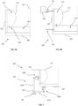
Figure 7 illustrates a cross-sectional view of adevice 300 having a mechanical system for applying lateral pressure. Thedevice 300 has aseat portion 305 and aside portion 310 having apad 315 secured thereto. Theseat portion 305 andside portion 310 are secured to asupport 325 by amechanical system 318. In one embodiment, the mechanical system includes a linkage mechanism 335 pivotally mounted 330 to thesupport 325. The linkage mechanism 335 is arranged to translate force applied in one direction into force applied in a second direction. Specifically, the linkage mechanism 335 translates displacement of theseat portion 305 in the vertical direction into displacement of theside portion 305 in a lateral or substantially horizontal direction. In one example, the linkage mechanism 335 has ahorizontal arm 335A extending from thepivotal connection 330 to the seat portion 305 aside arm 335B extending from thepivotal connection 330 to theside portion 310 in a substantially perpendicular direction to thehorizontal arm 335A. As shown inFigure 7 , a user sitting on theseat portion 305 will cause theseat portion 305 to lower (vertically) and the linkage mechanism 335 to rotate clockwise and push thepad 315 attached to theside portion 310 laterally into the user. The desired ratio of lateral to underbody pressure can be controlled by selecting the correct ratio of lengths of the horizontal 335A andside 335B arms. The length of theside arm 335B is preferably 1.25 to 1.65 the length of thehorizontal arm 335A. This has been found to achieve the desired ratio of lateral to underbody pressure. While a pivoting linkage mechanism 335 has been illustrated here, it would be apparent that other components suitable for translating load from a first direction to a substantially perpendicular second direction may be used in the present invention. For example, alternative linkage mechanisms, lever arms, gears, rotational springs or similar components may be used to translate force from the first to the second direction. To control the application of lateral force, a control arrangement may be incorporated into themechanical system 318. In one example, a first spring-dash-pot arrangement 320A is disposed between theseat portion 305 and the end of thehorizontal arm 335A and a second spring-dash-pot arrangement 320B is disposed between theside portion 310 and the end of theside arm 335B. While the illustratedcontrol arrangements side arm 335B compared to thehorizontal arm 335A. One exemplary device may comprise cone wheel gears connected the horizontal 335A and vertical 335B arms. In this case the amount of lateral pressure can be varied by adjusting the gear ratio provided by the gears. This adjustment may be made by the user or a carer or medical professional. Alternatively, thedevice 300 may comprise a system of pulleys or gears to apply lateral pressure at the desired ratio. A furtherexemplary device 300 may comprise a first rack and pinion arrangement (not shown) attached to theseat portion 305, a second rack and pinion arrangement (not shown) attached to theside portion 310 and one or more gears linking the first and second rack and pinion arrangements. In this case, displacement of theseat portion 310 would drive the first rack in the first direction which would cause the gear associated with the first rack to rotate and drive the gears linking between the first and second rack and pinion arrangements. The rotation of the gears would then result in the displacement of the second rack in the second direction. The gears linking the first and second rack and pinion arrangements may be configured to drive the second rack, and thus press theside portion 310 into the user, with the desired lateral pressure. A gearbox (not shown) may be further included in this example to provide a way of adjusting the ratio of lateral to underbody pressure applied by the rack and pinion arrangements. -
Figures 8A and 8B illustrate cross-sectional views of adevice 400 for wrapping around theuser 10 to apply lateral pressure. Thedevice 400 is illustrated in unwrapped (Figure 8A ) and wrapped (Figure 8B ) configurations. In one example, thedevice 400 has nineinflatable bladders 405 each connected to a pressurisedfluid reservoir 410, acontroller 412 configured to independently inflate each of thebladders 405 and apressure sensor 415 disposed across the surface of thebladders 405 and in data communication with thecontroller 412. By measuring the pressure distribution across the surface of thebladders 405, thecontroller 412 can ensure there is sufficient lateral pressure in relation to underbody pressure by inflating or deflatingindividual bladders 405 as required. As the lateral pressure may be applied by inflatingspecific bladders 405, there may be cases where there is no need for bladders beneath the user 10 (seeFigures 9 and 10 ). In this case, the underbody pressure may be determined by apressure sensor 415B disposed on theseat portion 205 directly. Thecontroller 412 subsequently calculates the appropriate lateral pressure to apply based off the measured underbody pressure. Once the desired lateral pressure is determined, thecontroller 412 can inflate or deflate thebladders 405 attached to theside portion 210 as required. The amount of lateral pressure is confirmed by apressure sensor 415A disposed on the surface of the bladder(s) 405 disposed between the bladder(s) 405 and the side of theuser 10. While not essential, it is preferable to measure the underbody pressure and lateral pressure to determine whether sufficient lateral support is being provided by thedevice 400. Auser interface 420 connected to thecontroller 412 is also provided to allow the user to adjust the support provided by thedevice 400. The user interface may take the form of a button, dial, knob, switch, touch screen or haptic switch. Theuser interface 420 may be connected to thecontroller 412 by a wired or wireless connection. Thepressure sensors pressure sensor 415 may include a customised arrangement of piezoelectric sensors arranged to measure underbody and lateral pressures at the necessary locations or may be a commercially available sensor for measuring pressure distribution on a surface. - The peak pressure from the underbody or lateral pressure measurements may be determined by an algorithm. For example, the peak pressure may be determined as the highest value recorded by the pressure sensor. Alternatively, the peak pressure may be determined from a mathematical curve fitted to measured pressure sensor data. One example of this would be to fit an isotropic von Mises distribution curve to the pressure sensor data and take the maximum of the distribution curve as the peak pressure. Alternatively, the
controller 412 may use a percentile, for example the 95th percentile, of the measured pressure data and take this as the peak pressure value. The percentile may be pre-programmed or selected by the user. The peak underbody pressure and peak lateral pressure may be determined in different ways. Once the peak lateral and underbody pressure have been determined, thecontroller 412 can determine the ratio of peak lateral to peak underbody pressure and control the bladder(s) 405 in the manner described above. -
Figure 10 illustrates a cross-sectional view of acable system 425 to maintain the shape of abladder 405. In one embodiment, thecable system 425 has sixpulleys 435 secured within theside portion 210 of the seat. Eachpulley 435 is driven by a motor (not shown) and can apply tension to acable 430 extending from eachpulley 435 to one or more respective attachment points 440 on an inner surface of thebladder 405. Thecable system 425 allows thebladder 405 to be kept under high pressure to achieve maximum expansion, while maintaining a desired cross-sectional profile. By increasing or decreasing the tension of each of thecables 430, thecontroller 412 is able to manipulate the profile of thebladder 405 and/or expand or contract thebladder 405. -
Figures 11A, 11B and 11C illustrate awearable device 500 for applying lateral pressure.Figure 11A illustrates one embodiment of thewearable device 500 having eightinflatable bladders 505 that can be inflated or deflated as required to provide the required amount of lateral pressure.Figure 11B illustrates an alternative embodiment of thewearable device 500 having asupport structure 510, abladder 505 secured to thesupport structure 510 and avalve 515 connecting thebladder 505 to an external pump (not shown). In this embodiment, thesupport structure 510 is a rigid structure that provides a reaction surface against when thebladder 505 can apply lateral pressure when inflated. Thebladder 505 andsupport structure 510 preferably incorporate pressure sensors (not shown) to measure the underbody and lateral pressures during operation of thedevice 500. Thedevice 500 preferably includes a controller to control the operation of thebladder 505 in a similar manner to that described above in relation to the earlier embodiments. Thevalve 515 may be manually controlled by theuser 10 or by a controller (not shown). The external pump may be a hand pump or a pressurised fluid reservoir.Figure 11C illustrates a further alternativewearable device 500 that is preferably activated only when the user is sat in, for example, awheelchair 600 having aseat 605, a back 610 and a frame 602 (see alsoFigure 12 ). In this embodiment, thedevice 500 is placed on theseat 605 and is secured to thewheelchair 600, for example, to theframe 602 or the back 610 of thewheelchair 600. As theframe 602 of the wheelchair provides a rigid structure for thebladder 505 to press against when inflated, there is no need for thewearable device 500 itself to be rigid and thus, thesupport structure 510 can be made from an elastic or flexible material. Further, as thedevice 500 is only activated when seated in thewheelchair 600, the external pump can be secured to thewheelchair 600. This provides a more user-friendly device 500, as the user is able to connect thedevice 500 to the external pump once they are sat in thewheelchair 600 and easily inflate thebladder 505. If the user needs to stand from the chair or adjust the pressure in thebladder 505, the user simply disconnects thedevice 500 from the external pump and thebladder 505 deflates and the user can get up from thewheelchair 600. This is particularly desirable, as theuser 10 is able benefit from thedevice 500 without having to carry all of the necessary components themselves to inflate and/or deflate thedevice 500, for example, the external pump. Thesupport structure 510 may incorporate pressure sensors (not shown) to measure the lateral pressures. Thewearable device 500 may also extend under theuser 10 such that theuser 10 sits on thewearable device 500 as opposed to theseat portion 605 of thewheelchair 600. In this case, the underbody pressure sensor may be incorporated in thesupport structure 510 under the user. Where thedevice 500 does not extend under theuser 10, the pressure sensor used to measure underbody pressure may be incorporated within thewheelchair 600 or disposed on top of theseat portion 605 of thewheelchair 600. - A
ratchet system 620 can also be used to bring the bladder(s) 505 into close proximity with the user in a controller manner independently of the internal pressure of the bladder(s) 505 (seeFigure 13 ). This is desirable as onedevice 500 can be made suitable for multiple body shapes and sizes. Thedevice 500 preferably includes mounting points (not shown) for securing to thewheelchair frame 602. -
Figures 14A and 14B illustrate perspective and plan views of adevice 700 having a series of actuatedpads 705 for applying lateral pressure. In this embodiment, thepads 705 are secured to asupport structure 710 and driven byrespective actuators 715 that are controlled by a controller (not shown). The controller receives data from pressure sensors disposed on thepads 705 andseat 605 that measure lateral and underbody pressures respectively. Having received the pressure sensor data, the controller is able to control theactuators 715 to press thepads 705 into theuser 10 at the desired level of lateral pressure based on the measured underbody pressure. The controller may be connected to theactuators 715 and pressure sensors be a wired or wireless connection. Theactuator 715 may include a linear motor or a hydraulic piston. While this embodiment is described with a series ofpads 705, it would be apparent that one or more inflatable bladders would be compatible with this embodiment. Thepads 705 may include layers of one or more foams known in the art. -
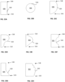
Figures 15A to 15H illustrate cross-sectional profiles ofexemplary bladders 505 andpads 705 suitable for the presently described devices viewed in a vertical plane. While the subsequent description is directed towardsbladders 505, it would be apparent thatpads 705 may also have a profile described below. Thebladder 505 may have an outer surface defining a profile having afirst end 525 and asecond end 530 opposed to thefirst end 525. The outer surface may form a rectangular or substantially circular profile. Alternatively, theouter surface 520 may have an arcuate profile having one or more points of inflexion. Thebladder 505 may have a first width at thefirst end 525 and a second width at thesecond end 530, and the second width may be larger, smaller or equal to the first width. The widest length of the profile may be between the first 525 and second 530 ends. The shortest length of the profile may be halfway between the first 525 and second 530 ends. Theouter surface 520 may have one or more substantially straight sections. Theouter surface 520 may have a profile combining one or more substantially curved sections with one or more substantially straight sections. Theouter surface 520 may form a series of adjoining arcuate sections. Theouter surface 520 may have two or more arcuate sections, each arcuate section having a different radius of curvature. - While the devices have been described in the context of a wheelchair, it would be apparent that the devices may be secured to or retrofitted to other chairs or furniture or medical device. Similarly, while retrofit device may be desirable in some cases, it would be apparent that in other cases, a chair incorporating the elements of the device would be preferable. For example, the device may be incorporated into a bed, an orthotic or a prosthetic.
- Throughout the description and claims of this specification, the words "comprise" and "contain" and variations of them mean "including but not limited to", and they are not intended to (and do not) exclude other moieties, additives, components, integers or steps. Throughout the description and claims of this specification, the singular encompasses the plural unless the context otherwise requires. In particular, where the indefinite article is used, the specification is to be understood as contemplating plurality as well as singularity, unless the context requires otherwise.
- Features, integers or characteristics described in conjunction with a particular aspect, embodiment or example of the invention are to be understood to be applicable to any other aspect, embodiment or example described herein unless incompatible therewith. All of the features disclosed in this specification (including any accompanying claims, abstract and drawings), and/or all of the steps of any method or process so disclosed, may be combined in any combination, except combinations where at least some of such features and/or steps are mutually exclusive. The invention is not restricted to the details of any foregoing embodiments. The invention extends to any novel one, or any novel combination, of the features disclosed in this specification (including any accompanying claims, abstract and drawings), or to any novel one, or any novel combination, of the steps of any method or process so disclosed.
Claims (15)
- A method of supporting a body part (16) having a bony prominence (16A), a layer of soft tissue (12) surrounding the bony prominence and a skin layer (14) covering the soft tissue (12), the method comprising:providing a device (100, 200, 300, 400, 500, 700) comprising: a first portion (105, 205, 305, 405) configured to support a body part (16) having a bony prominence (16A), a layer of soft tissue (12) surrounding the bony prominence (16A) and a skin layer (14) covering the soft tissue (12), wherein, in use, the body part (16) applies a first pressure to the first portion (105, 205, 305) in a first direction; means for detecting the first pressure; and a second portion (110, 210, 310, 405, 505) having means (115, 212, 315, 410, 715) for applying a second pressure to the body part (16) in a second direction substantially perpendicular to the first direction;detecting the first pressure;determining the second pressure based on a user parameter; andapplying the second pressure to the body part (16) in the second direction at a pre-determined ratio relative to the first pressure using said means (115, 212, 315, 410, 715) for applying the second pressure to substantially reduce bulging of the soft tissue (12) surrounding the bony prominence (16A) so as to reduce deviatoric stresses in the soft tissue (12) in close proximity to the bony prominence (16A),wherein the pre-determined ratio of the second pressure to the first pressure is between 0.5 and 0.8.
- A method according to claim 1, wherein the user parameter comprises one or more of: waist size; body mass index; and mass.
- A method according to any preceding claim, wherein the means (115, 212, 315, 410, 715) for applying the second pressure is arranged to: increase the second pressure if the ratio between the second pressure and the first pressure is below the pre-determined ratio, or decrease the second pressure if the ratio between the second pressure and the first pressure is above the pre-determined ratio.
- A method according to any preceding claim, wherein the first direction is substantially vertical.
- A device (100, 200, 300, 400, 500, 700) for supporting a body part (16) having a bony prominence (16A), a layer of soft tissue (12) surrounding the bony prominence and a skin layer (14) covering the soft tissue (12), the device (100, 200, 300, 400, 500, 700) comprising:a first portion (105, 205, 305, 405) configured to support the body part (16);means (415B) for detecting a first pressure applied by the body part (16) to the first portion (105, 205, 305, 405) in a first direction; anda second portion (110, 210, 310, 405, 505, 705) having means (115, 212, 315, 410, 715) for applying a second pressure to the body part from a second direction substantially perpendicular to the first direction;wherein said means (115, 212, 315, 410, 715) for applying the second pressure is configured to apply the second pressure in the second direction at a pre-determined ratio relative to the first pressure to substantially reduce bulging of the soft tissue (12) surrounding the bony prominence (16A) so as to reduce deviatoric stresses in the soft tissue (12) in close proximity to the bony prominence (16A), andwherein the pre-determined ratio of the second pressure to the first pressure is between 0.5 and 0.8.
- A device (300) according to claim 5, further comprising a base portion (325), wherein the means for applying the second pressure to the body part comprises a mechanical linkage (318) connected to the base portion (325), wherein the mechanical linkage (318) is connected to the first portion (305) at a first end, wherein the mechanical linkage (318) is connected to the second portion (310) at a second end, and wherein the mechanical linkage (318) is arranged to translate said first pressure applied in the first direction into said second pressure applied to the body part in the second direction.
- A device (300) according to claim 6, wherein the mechanical linkage is pivotally connected to the base portion (325) at a pivot point (330), wherein the mechanical linkage (318) comprises a first arm (335A) having a first length extending from the pivot point to the first portion (305) and a second arm (335B) having a second length extending from the pivot point (330) to the second portion (310), wherein the mechanical linkage (318) is configured to pivot about the pivot point (330) upon application of the first pressure, and wherein the second arm (335B) is configured to apply the second pressure at the pre-determined ratio based on the proportion of the second length to the first length.
- A device (200) according to claim 5, wherein the first portion (205) comprises a first bladder (207), wherein the second portion (210) comprises a second bladder (212) in fluid communication with the first bladder (207) via a first valve (220), and wherein the first valve (220) is configured to maintain the ratio between the first and second pressures at the pre-determined ratio.
- A device (400, 700) according to claim 5, further comprising a first pressure sensor (415B) configured to measure a first contact pressure on the first portion (405), a second pressure sensor (415A) configured to measure a second contact pressure on the second portion (405), and a controller (412) having a memory for storing the pre-determined ratio, wherein the controller (412) is in data communication with the first pressure sensor (415B), the second pressure sensor (415A), and the means (410) for applying the second pressure, wherein the controller (412) is configured to calculate the ratio between the second contact pressure and the first contact pressure, wherein the controller (412) is configured to compare the calculated ratio with the pre-determined ratio, and wherein the controller (412) is configured to actuate the means (410) for applying the second pressure such that the second pressure is applied at the pre-determined ratio to the first pressure.
- A device (400, 700) according to claim 9, wherein the first (405) and second (405) portions comprise respective contact surfaces configured to contact the body part (16), wherein the first pressure sensor (415B) comprises a first sensor array configured to measure a pressure distribution across the first contact surface, wherein the second pressure sensor (415A) comprises a second sensor array configured to measure a pressure distribution across the second contact surface, wherein the controller (412) is configured to calculate respective first and second peak pressures at the first and second contact surfaces based on the pressure distribution data received from the respective first and second sensor arrays, and wherein the calculated ratio is based on the calculated first and second peak pressures.
- A device (400) according to claim 9 or claim 10, wherein the means for applying the second pressure comprises: a fluid reservoir (410), and a bladder (405) in fluid communication with the fluid reservoir (410) via a first valve, and wherein the controller (412) is configured to pump fluid from the fluid reservoir (410) into the bladder (405) such that the second pressure is applied at the pre-determined ratio to the first pressure.
- A device (400) according to claim 11, wherein the means (410) for applying the second pressure further comprises: a motor and at least one tensile element (430), wherein the at least one tensile element (43) extends between the motor at a first end and an inner surface of the bladder (405) at a second end, wherein the controller (410) is in data communication with the motor, and wherein the controller (410) is configured to change the tension in the at least one tensile element (430), whereby to control the shape of the bladder (405).
- A device (400) according to claim 12, wherein the controller (410) is configured to change the tension in the at least one tensile element (430) in order to maintain the shape of the bladder (405) or increase the volume of the bladder (405).
- A device (700) according to claim 9 or claim 10, wherein the means for applying the second pressure further comprises: a motor (715) and at least one member (705) secured to the motor, and wherein the controller is configured to press the at least one member (705) against the body part (16) such that the second pressure is applied at the pre-determined ratio to the first pressure.
- A device (700) according to claim 9 or claim 10, wherein the means (715) for applying the second pressure further comprises a hydraulic piston connected to the at least one member (705), and wherein the controller is configured to drive the hydraulic piston.
Applications Claiming Priority (2)
| Application Number | Priority Date | Filing Date | Title |
|---|---|---|---|
| GBGB1814813.0A GB201814813D0 (en) | 2018-09-12 | 2018-09-12 | Device for supporting a body part |
| PCT/GB2019/052549 WO2020053586A1 (en) | 2018-09-12 | 2019-09-12 | Device for supporting a body part |
Publications (2)
| Publication Number | Publication Date |
|---|---|
| EP3849487A1 EP3849487A1 (en) | 2021-07-21 |
| EP3849487B1 true EP3849487B1 (en) | 2024-07-10 |
Family
ID=63921209
Family Applications (1)
| Application Number | Title | Priority Date | Filing Date |
|---|---|---|---|
| EP19770153.5A Active EP3849487B1 (en) | 2018-09-12 | 2019-09-12 | Device for supporting a body part |
Country Status (6)
| Country | Link |
|---|---|
| US (1) | US11998497B2 (en) |
| EP (1) | EP3849487B1 (en) |
| AU (1) | AU2019340885A1 (en) |
| CA (1) | CA3112518A1 (en) |
| GB (1) | GB201814813D0 (en) |
| WO (1) | WO2020053586A1 (en) |
Cited By (1)
| Publication number | Priority date | Publication date | Assignee | Title |
|---|---|---|---|---|
| TWI916243B (en) | 2025-04-15 | 2026-02-21 | 長庚學校財團法人長庚科技大學 | Wheelchair with assistive standing function |
Families Citing this family (1)
| Publication number | Priority date | Publication date | Assignee | Title |
|---|---|---|---|---|
| EP4482359A4 (en) * | 2022-02-21 | 2026-02-25 | Sizewise Rentals L L C | UNIVERSAL AIR SURFACE |
Family Cites Families (9)
| Publication number | Priority date | Publication date | Assignee | Title |
|---|---|---|---|---|
| US5558398A (en) * | 1993-11-08 | 1996-09-24 | Santos; James P. | Self-adjusting seating system |
| GB2370222A (en) | 2000-12-19 | 2002-06-26 | Autoliv Dev | Vehicle seat accessory providing lumbar / pelvic / shoulder support induced by weight of sitting person |
| EP1639941A1 (en) * | 2003-06-20 | 2006-03-29 | Matsushita Electric Industrial Co., Ltd. | Sleeping device and sleeper's in-bed state detection method |
| WO2011082176A1 (en) | 2009-12-29 | 2011-07-07 | University Of Denver | Self-adaptive pneumatic cast |
| US10485691B2 (en) * | 2011-07-22 | 2019-11-26 | Prs Medical Technologies, Inc. | Independently adjustable support system |
| US9339407B2 (en) * | 2011-07-22 | 2016-05-17 | Prs Medical Technologies, Inc. | Apparatus and methods for conforming a support to a body |
| US9326905B2 (en) * | 2011-07-22 | 2016-05-03 | Prs Medical Technologies, Inc. | Apparatus and methods for adjusting a support to a body |
| US20130255699A1 (en) | 2012-04-02 | 2013-10-03 | TurnCare, Inc. | Patient-orienting alternating pressure decubitus prevention support apparatus |
| US10973344B2 (en) * | 2012-04-30 | 2021-04-13 | Xsensor Technology Corporation | Bedding system with a CNN based machine vision process |
-
2018
- 2018-09-12 GB GBGB1814813.0A patent/GB201814813D0/en not_active Ceased
-
2019
- 2019-09-12 WO PCT/GB2019/052549 patent/WO2020053586A1/en not_active Ceased
- 2019-09-12 CA CA3112518A patent/CA3112518A1/en active Pending
- 2019-09-12 US US17/275,852 patent/US11998497B2/en active Active
- 2019-09-12 AU AU2019340885A patent/AU2019340885A1/en not_active Abandoned
- 2019-09-12 EP EP19770153.5A patent/EP3849487B1/en active Active
Cited By (1)
| Publication number | Priority date | Publication date | Assignee | Title |
|---|---|---|---|---|
| TWI916243B (en) | 2025-04-15 | 2026-02-21 | 長庚學校財團法人長庚科技大學 | Wheelchair with assistive standing function |
Also Published As
| Publication number | Publication date |
|---|---|
| CA3112518A1 (en) | 2020-03-19 |
| AU2019340885A1 (en) | 2021-04-08 |
| US20220040017A1 (en) | 2022-02-10 |
| US11998497B2 (en) | 2024-06-04 |
| GB201814813D0 (en) | 2018-10-24 |
| EP3849487A1 (en) | 2021-07-21 |
| WO2020053586A1 (en) | 2020-03-19 |
Similar Documents
| Publication | Publication Date | Title |
|---|---|---|
| US20230123631A1 (en) | Independently adjustable support system | |
| US9750655B2 (en) | Conformable support system | |
| US6789284B2 (en) | Inflatable support | |
| US8572783B2 (en) | Device for supporting a user's body | |
| JP3959116B2 (en) | Steady pressure seat system | |
| KR102785599B1 (en) | Body Positioning Device | |
| EP2257201B1 (en) | Assembly for adapting a support surface in a wave shape | |
| US20130180530A1 (en) | Adjustable support system | |
| WO2009102968A1 (en) | Apparatuses and methods for automatic pillow adjustment | |
| US20130092175A1 (en) | Apparatus and methods for adjusting a support to a body | |
| CA2892048A1 (en) | Adjustable support system | |
| US11998497B2 (en) | Device for supporting a body part | |
| EP3697362A1 (en) | Two-in-one mattress with air mattress and memory foam for patient care | |
| CN109106535A (en) | A kind of pressure sore prevention device for bow-backed patient | |
| CA2202222A1 (en) | Portable orthopedic bed |
Legal Events
| Date | Code | Title | Description |
|---|---|---|---|
| STAA | Information on the status of an ep patent application or granted ep patent |
Free format text: STATUS: UNKNOWN |
|
| STAA | Information on the status of an ep patent application or granted ep patent |
Free format text: STATUS: THE INTERNATIONAL PUBLICATION HAS BEEN MADE |
|
| PUAI | Public reference made under article 153(3) epc to a published international application that has entered the european phase |
Free format text: ORIGINAL CODE: 0009012 |
|
| STAA | Information on the status of an ep patent application or granted ep patent |
Free format text: STATUS: REQUEST FOR EXAMINATION WAS MADE |
|
| 17P | Request for examination filed |
Effective date: 20210330 |
|
| AK | Designated contracting states |
Kind code of ref document: A1 Designated state(s): AL AT BE BG CH CY CZ DE DK EE ES FI FR GB GR HR HU IE IS IT LI LT LU LV MC MK MT NL NO PL PT RO RS SE SI SK SM TR |
|
| DAV | Request for validation of the european patent (deleted) | ||
| DAX | Request for extension of the european patent (deleted) | ||
| RAP1 | Party data changed (applicant data changed or rights of an application transferred) |
Owner name: IMPERIAL COLLEGE INNOVATIONS LIMITED |
|
| GRAP | Despatch of communication of intention to grant a patent |
Free format text: ORIGINAL CODE: EPIDOSNIGR1 |
|
| STAA | Information on the status of an ep patent application or granted ep patent |
Free format text: STATUS: GRANT OF PATENT IS INTENDED |
|
| INTG | Intention to grant announced |
Effective date: 20240306 |
|
| GRAS | Grant fee paid |
Free format text: ORIGINAL CODE: EPIDOSNIGR3 |
|
| GRAA | (expected) grant |
Free format text: ORIGINAL CODE: 0009210 |
|
| STAA | Information on the status of an ep patent application or granted ep patent |
Free format text: STATUS: THE PATENT HAS BEEN GRANTED |
|
| AK | Designated contracting states |
Kind code of ref document: B1 Designated state(s): AL AT BE BG CH CY CZ DE DK EE ES FI FR GB GR HR HU IE IS IT LI LT LU LV MC MK MT NL NO PL PT RO RS SE SI SK SM TR |
|
| REG | Reference to a national code |
Ref country code: CH Ref legal event code: EP |
|
| REG | Reference to a national code |
Ref country code: DE Ref legal event code: R096 Ref document number: 602019055008 Country of ref document: DE |
|
| REG | Reference to a national code |
Ref country code: LT Ref legal event code: MG9D |
|
| REG | Reference to a national code |
Ref country code: NL Ref legal event code: MP Effective date: 20240710 |
|
| PG25 | Lapsed in a contracting state [announced via postgrant information from national office to epo] |
Ref country code: PT Free format text: LAPSE BECAUSE OF FAILURE TO SUBMIT A TRANSLATION OF THE DESCRIPTION OR TO PAY THE FEE WITHIN THE PRESCRIBED TIME-LIMIT Effective date: 20241111 |
|
| REG | Reference to a national code |
Ref country code: AT Ref legal event code: MK05 Ref document number: 1701410 Country of ref document: AT Kind code of ref document: T Effective date: 20240710 |
|
| PG25 | Lapsed in a contracting state [announced via postgrant information from national office to epo] |
Ref country code: NL Free format text: LAPSE BECAUSE OF FAILURE TO SUBMIT A TRANSLATION OF THE DESCRIPTION OR TO PAY THE FEE WITHIN THE PRESCRIBED TIME-LIMIT Effective date: 20240710 |
|
| PG25 | Lapsed in a contracting state [announced via postgrant information from national office to epo] |
Ref country code: PT Free format text: LAPSE BECAUSE OF FAILURE TO SUBMIT A TRANSLATION OF THE DESCRIPTION OR TO PAY THE FEE WITHIN THE PRESCRIBED TIME-LIMIT Effective date: 20241111 Ref country code: NL Free format text: LAPSE BECAUSE OF FAILURE TO SUBMIT A TRANSLATION OF THE DESCRIPTION OR TO PAY THE FEE WITHIN THE PRESCRIBED TIME-LIMIT Effective date: 20240710 |
|
| PG25 | Lapsed in a contracting state [announced via postgrant information from national office to epo] |
Ref country code: NO Free format text: LAPSE BECAUSE OF FAILURE TO SUBMIT A TRANSLATION OF THE DESCRIPTION OR TO PAY THE FEE WITHIN THE PRESCRIBED TIME-LIMIT Effective date: 20241010 |
|
| PG25 | Lapsed in a contracting state [announced via postgrant information from national office to epo] |
Ref country code: FI Free format text: LAPSE BECAUSE OF FAILURE TO SUBMIT A TRANSLATION OF THE DESCRIPTION OR TO PAY THE FEE WITHIN THE PRESCRIBED TIME-LIMIT Effective date: 20240710 Ref country code: GR Free format text: LAPSE BECAUSE OF FAILURE TO SUBMIT A TRANSLATION OF THE DESCRIPTION OR TO PAY THE FEE WITHIN THE PRESCRIBED TIME-LIMIT Effective date: 20241011 Ref country code: PL Free format text: LAPSE BECAUSE OF FAILURE TO SUBMIT A TRANSLATION OF THE DESCRIPTION OR TO PAY THE FEE WITHIN THE PRESCRIBED TIME-LIMIT Effective date: 20240710 |
|
| PG25 | Lapsed in a contracting state [announced via postgrant information from national office to epo] |
Ref country code: BG Free format text: LAPSE BECAUSE OF FAILURE TO SUBMIT A TRANSLATION OF THE DESCRIPTION OR TO PAY THE FEE WITHIN THE PRESCRIBED TIME-LIMIT Effective date: 20240710 |
|
| PG25 | Lapsed in a contracting state [announced via postgrant information from national office to epo] |
Ref country code: LV Free format text: LAPSE BECAUSE OF FAILURE TO SUBMIT A TRANSLATION OF THE DESCRIPTION OR TO PAY THE FEE WITHIN THE PRESCRIBED TIME-LIMIT Effective date: 20240710 |
|
| PG25 | Lapsed in a contracting state [announced via postgrant information from national office to epo] |
Ref country code: AT Free format text: LAPSE BECAUSE OF FAILURE TO SUBMIT A TRANSLATION OF THE DESCRIPTION OR TO PAY THE FEE WITHIN THE PRESCRIBED TIME-LIMIT Effective date: 20240710 Ref country code: IS Free format text: LAPSE BECAUSE OF FAILURE TO SUBMIT A TRANSLATION OF THE DESCRIPTION OR TO PAY THE FEE WITHIN THE PRESCRIBED TIME-LIMIT Effective date: 20241110 |
|
| PG25 | Lapsed in a contracting state [announced via postgrant information from national office to epo] |
Ref country code: HR Free format text: LAPSE BECAUSE OF FAILURE TO SUBMIT A TRANSLATION OF THE DESCRIPTION OR TO PAY THE FEE WITHIN THE PRESCRIBED TIME-LIMIT Effective date: 20240710 |
|
| PG25 | Lapsed in a contracting state [announced via postgrant information from national office to epo] |
Ref country code: ES Free format text: LAPSE BECAUSE OF FAILURE TO SUBMIT A TRANSLATION OF THE DESCRIPTION OR TO PAY THE FEE WITHIN THE PRESCRIBED TIME-LIMIT Effective date: 20240710 Ref country code: RS Free format text: LAPSE BECAUSE OF FAILURE TO SUBMIT A TRANSLATION OF THE DESCRIPTION OR TO PAY THE FEE WITHIN THE PRESCRIBED TIME-LIMIT Effective date: 20241010 |
|
| PG25 | Lapsed in a contracting state [announced via postgrant information from national office to epo] |
Ref country code: RS Free format text: LAPSE BECAUSE OF FAILURE TO SUBMIT A TRANSLATION OF THE DESCRIPTION OR TO PAY THE FEE WITHIN THE PRESCRIBED TIME-LIMIT Effective date: 20241010 Ref country code: PL Free format text: LAPSE BECAUSE OF FAILURE TO SUBMIT A TRANSLATION OF THE DESCRIPTION OR TO PAY THE FEE WITHIN THE PRESCRIBED TIME-LIMIT Effective date: 20240710 Ref country code: NO Free format text: LAPSE BECAUSE OF FAILURE TO SUBMIT A TRANSLATION OF THE DESCRIPTION OR TO PAY THE FEE WITHIN THE PRESCRIBED TIME-LIMIT Effective date: 20241010 Ref country code: LV Free format text: LAPSE BECAUSE OF FAILURE TO SUBMIT A TRANSLATION OF THE DESCRIPTION OR TO PAY THE FEE WITHIN THE PRESCRIBED TIME-LIMIT Effective date: 20240710 Ref country code: IS Free format text: LAPSE BECAUSE OF FAILURE TO SUBMIT A TRANSLATION OF THE DESCRIPTION OR TO PAY THE FEE WITHIN THE PRESCRIBED TIME-LIMIT Effective date: 20241110 Ref country code: HR Free format text: LAPSE BECAUSE OF FAILURE TO SUBMIT A TRANSLATION OF THE DESCRIPTION OR TO PAY THE FEE WITHIN THE PRESCRIBED TIME-LIMIT Effective date: 20240710 Ref country code: GR Free format text: LAPSE BECAUSE OF FAILURE TO SUBMIT A TRANSLATION OF THE DESCRIPTION OR TO PAY THE FEE WITHIN THE PRESCRIBED TIME-LIMIT Effective date: 20241011 Ref country code: FI Free format text: LAPSE BECAUSE OF FAILURE TO SUBMIT A TRANSLATION OF THE DESCRIPTION OR TO PAY THE FEE WITHIN THE PRESCRIBED TIME-LIMIT Effective date: 20240710 Ref country code: ES Free format text: LAPSE BECAUSE OF FAILURE TO SUBMIT A TRANSLATION OF THE DESCRIPTION OR TO PAY THE FEE WITHIN THE PRESCRIBED TIME-LIMIT Effective date: 20240710 Ref country code: BG Free format text: LAPSE BECAUSE OF FAILURE TO SUBMIT A TRANSLATION OF THE DESCRIPTION OR TO PAY THE FEE WITHIN THE PRESCRIBED TIME-LIMIT Effective date: 20240710 Ref country code: AT Free format text: LAPSE BECAUSE OF FAILURE TO SUBMIT A TRANSLATION OF THE DESCRIPTION OR TO PAY THE FEE WITHIN THE PRESCRIBED TIME-LIMIT Effective date: 20240710 |
|
| REG | Reference to a national code |
Ref country code: DE Ref legal event code: R119 Ref document number: 602019055008 Country of ref document: DE |
|
| PG25 | Lapsed in a contracting state [announced via postgrant information from national office to epo] |
Ref country code: RO Free format text: LAPSE BECAUSE OF FAILURE TO SUBMIT A TRANSLATION OF THE DESCRIPTION OR TO PAY THE FEE WITHIN THE PRESCRIBED TIME-LIMIT Effective date: 20240710 Ref country code: DK Free format text: LAPSE BECAUSE OF FAILURE TO SUBMIT A TRANSLATION OF THE DESCRIPTION OR TO PAY THE FEE WITHIN THE PRESCRIBED TIME-LIMIT Effective date: 20240710 Ref country code: SM Free format text: LAPSE BECAUSE OF FAILURE TO SUBMIT A TRANSLATION OF THE DESCRIPTION OR TO PAY THE FEE WITHIN THE PRESCRIBED TIME-LIMIT Effective date: 20240710 |
|
| PG25 | Lapsed in a contracting state [announced via postgrant information from national office to epo] |
Ref country code: EE Free format text: LAPSE BECAUSE OF FAILURE TO SUBMIT A TRANSLATION OF THE DESCRIPTION OR TO PAY THE FEE WITHIN THE PRESCRIBED TIME-LIMIT Effective date: 20240710 Ref country code: MC Free format text: LAPSE BECAUSE OF FAILURE TO SUBMIT A TRANSLATION OF THE DESCRIPTION OR TO PAY THE FEE WITHIN THE PRESCRIBED TIME-LIMIT Effective date: 20240710 |
|
| PG25 | Lapsed in a contracting state [announced via postgrant information from national office to epo] |
Ref country code: CZ Free format text: LAPSE BECAUSE OF FAILURE TO SUBMIT A TRANSLATION OF THE DESCRIPTION OR TO PAY THE FEE WITHIN THE PRESCRIBED TIME-LIMIT Effective date: 20240710 |
|
| PG25 | Lapsed in a contracting state [announced via postgrant information from national office to epo] |
Ref country code: IT Free format text: LAPSE BECAUSE OF FAILURE TO SUBMIT A TRANSLATION OF THE DESCRIPTION OR TO PAY THE FEE WITHIN THE PRESCRIBED TIME-LIMIT Effective date: 20240710 Ref country code: SK Free format text: LAPSE BECAUSE OF FAILURE TO SUBMIT A TRANSLATION OF THE DESCRIPTION OR TO PAY THE FEE WITHIN THE PRESCRIBED TIME-LIMIT Effective date: 20240710 |
|
| REG | Reference to a national code |
Ref country code: CH Ref legal event code: PL |
|
| PLBE | No opposition filed within time limit |
Free format text: ORIGINAL CODE: 0009261 |
|
| STAA | Information on the status of an ep patent application or granted ep patent |
Free format text: STATUS: NO OPPOSITION FILED WITHIN TIME LIMIT |
|
| PG25 | Lapsed in a contracting state [announced via postgrant information from national office to epo] |
Ref country code: LU Free format text: LAPSE BECAUSE OF NON-PAYMENT OF DUE FEES Effective date: 20240912 |
|
| 26N | No opposition filed |
Effective date: 20250411 |
|
| PG25 | Lapsed in a contracting state [announced via postgrant information from national office to epo] |
Ref country code: DE Free format text: LAPSE BECAUSE OF NON-PAYMENT OF DUE FEES Effective date: 20250401 |
|
| REG | Reference to a national code |
Ref country code: BE Ref legal event code: MM Effective date: 20240930 |
|
| PG25 | Lapsed in a contracting state [announced via postgrant information from national office to epo] |
Ref country code: BE Free format text: LAPSE BECAUSE OF NON-PAYMENT OF DUE FEES Effective date: 20240930 |
|
| PG25 | Lapsed in a contracting state [announced via postgrant information from national office to epo] |
Ref country code: FR Free format text: LAPSE BECAUSE OF NON-PAYMENT OF DUE FEES Effective date: 20240930 |
|
| PG25 | Lapsed in a contracting state [announced via postgrant information from national office to epo] |
Ref country code: CH Free format text: LAPSE BECAUSE OF NON-PAYMENT OF DUE FEES Effective date: 20240930 |
|
| PG25 | Lapsed in a contracting state [announced via postgrant information from national office to epo] |
Ref country code: IE Free format text: LAPSE BECAUSE OF NON-PAYMENT OF DUE FEES Effective date: 20240912 |
|
| PG25 | Lapsed in a contracting state [announced via postgrant information from national office to epo] |
Ref country code: SE Free format text: LAPSE BECAUSE OF FAILURE TO SUBMIT A TRANSLATION OF THE DESCRIPTION OR TO PAY THE FEE WITHIN THE PRESCRIBED TIME-LIMIT Effective date: 20240710 |
|
| PGFP | Annual fee paid to national office [announced via postgrant information from national office to epo] |
Ref country code: GB Payment date: 20251009 Year of fee payment: 7 |
|
| PG25 | Lapsed in a contracting state [announced via postgrant information from national office to epo] |
Ref country code: CY Free format text: LAPSE BECAUSE OF FAILURE TO SUBMIT A TRANSLATION OF THE DESCRIPTION OR TO PAY THE FEE WITHIN THE PRESCRIBED TIME-LIMIT; INVALID AB INITIO Effective date: 20190912 |
|
| PG25 | Lapsed in a contracting state [announced via postgrant information from national office to epo] |
Ref country code: HU Free format text: LAPSE BECAUSE OF FAILURE TO SUBMIT A TRANSLATION OF THE DESCRIPTION OR TO PAY THE FEE WITHIN THE PRESCRIBED TIME-LIMIT; INVALID AB INITIO Effective date: 20190912 |