EP3849162A1 - Mobile terminal - Google Patents
Mobile terminal Download PDFInfo
- Publication number
- EP3849162A1 EP3849162A1 EP19857431.1A EP19857431A EP3849162A1 EP 3849162 A1 EP3849162 A1 EP 3849162A1 EP 19857431 A EP19857431 A EP 19857431A EP 3849162 A1 EP3849162 A1 EP 3849162A1
- Authority
- EP
- European Patent Office
- Prior art keywords
- side wall
- image capturing
- bolt
- module
- capturing device
- Prior art date
- Legal status (The legal status is an assumption and is not a legal conclusion. Google has not performed a legal analysis and makes no representation as to the accuracy of the status listed.)
- Granted
Links
Images



Classifications
-
- H—ELECTRICITY
- H04—ELECTRIC COMMUNICATION TECHNIQUE
- H04M—TELEPHONIC COMMUNICATION
- H04M1/00—Substation equipment, e.g. for use by subscribers
- H04M1/02—Constructional features of telephone sets
- H04M1/0202—Portable telephone sets, e.g. cordless phones, mobile phones or bar type handsets
- H04M1/0254—Portable telephone sets, e.g. cordless phones, mobile phones or bar type handsets comprising one or a plurality of mechanically detachable modules
- H04M1/0256—Portable telephone sets, e.g. cordless phones, mobile phones or bar type handsets comprising one or a plurality of mechanically detachable modules wherein the modules are operable in the detached state, e.g. one module for the user interface and one module for the transceiver
-
- G—PHYSICS
- G06—COMPUTING OR CALCULATING; COUNTING
- G06F—ELECTRIC DIGITAL DATA PROCESSING
- G06F1/00—Details not covered by groups G06F3/00 - G06F13/00 and G06F21/00
- G06F1/16—Constructional details or arrangements
- G06F1/1613—Constructional details or arrangements for portable computers
- G06F1/1626—Constructional details or arrangements for portable computers with a single-body enclosure integrating a flat display, e.g. Personal Digital Assistants [PDAs]
-
- G—PHYSICS
- G06—COMPUTING OR CALCULATING; COUNTING
- G06F—ELECTRIC DIGITAL DATA PROCESSING
- G06F1/00—Details not covered by groups G06F3/00 - G06F13/00 and G06F21/00
- G06F1/16—Constructional details or arrangements
- G06F1/1613—Constructional details or arrangements for portable computers
- G06F1/1633—Constructional details or arrangements of portable computers not specific to the type of enclosures covered by groups G06F1/1615 - G06F1/1626
- G06F1/1684—Constructional details or arrangements related to integrated I/O peripherals not covered by groups G06F1/1635 - G06F1/1675
- G06F1/1686—Constructional details or arrangements related to integrated I/O peripherals not covered by groups G06F1/1635 - G06F1/1675 the I/O peripheral being an integrated camera
-
- H—ELECTRICITY
- H04—ELECTRIC COMMUNICATION TECHNIQUE
- H04M—TELEPHONIC COMMUNICATION
- H04M1/00—Substation equipment, e.g. for use by subscribers
- H04M1/02—Constructional features of telephone sets
- H04M1/0202—Portable telephone sets, e.g. cordless phones, mobile phones or bar type handsets
- H04M1/026—Details of the structure or mounting of specific components
- H04M1/0264—Details of the structure or mounting of specific components for a camera module assembly
-
- H—ELECTRICITY
- H04—ELECTRIC COMMUNICATION TECHNIQUE
- H04N—PICTORIAL COMMUNICATION, e.g. TELEVISION
- H04N23/00—Cameras or camera modules comprising electronic image sensors; Control thereof
- H04N23/50—Constructional details
- H04N23/53—Constructional details of electronic viewfinders, e.g. rotatable or detachable
- H04N23/531—Constructional details of electronic viewfinders, e.g. rotatable or detachable being rotatable or detachable
-
- H—ELECTRICITY
- H04—ELECTRIC COMMUNICATION TECHNIQUE
- H04N—PICTORIAL COMMUNICATION, e.g. TELEVISION
- H04N23/00—Cameras or camera modules comprising electronic image sensors; Control thereof
- H04N23/57—Mechanical or electrical details of cameras or camera modules specially adapted for being embedded in other devices
-
- H—ELECTRICITY
- H04—ELECTRIC COMMUNICATION TECHNIQUE
- H04M—TELEPHONIC COMMUNICATION
- H04M1/00—Substation equipment, e.g. for use by subscribers
- H04M1/72—Mobile telephones; Cordless telephones, i.e. devices for establishing wireless links to base stations without route selection
- H04M1/724—User interfaces specially adapted for cordless or mobile telephones
- H04M1/72403—User interfaces specially adapted for cordless or mobile telephones with means for local support of applications that increase the functionality
- H04M1/72409—User interfaces specially adapted for cordless or mobile telephones with means for local support of applications that increase the functionality by interfacing with external accessories
- H04M1/72412—User interfaces specially adapted for cordless or mobile telephones with means for local support of applications that increase the functionality by interfacing with external accessories using two-way short-range wireless interfaces
Definitions
- the present disclosure relates to the field of mobile terminal technologies, and more particularly, to a mobile terminal.
- Mobile terminals (phones, tablets, etc.) are generally equipped with cameras, which are configured to provide functions such as video calling and shooting. However, shooting scenarios of the camera are relatively monotonous.
- the disclosure provides a mobile terminal.
- a mobile terminal includes a terminal device, an image capturing device and a locking mechanism.
- the terminal device comprises a display screen, a first power supply module, and a first wireless communication module, wherein the first power supply module is configured to supply power to the display screen and the first wireless communication module, and the terminal device defines a mounting recess on a side thereof facing away from a display area of the display screen.
- the image capturing device comprises a casing, a camera module, a second power supply module, and a second wireless communication module, wherein the second power supply module is configured to supply power to the camera module and the second wireless communication module, the camera module and the second power supply module are arranged in the casing, the camera module has a light incident surface exposed from the casing; the image capturing device is configured to be mounted in the mounting recess, thereby making the light incident surface be exposed on the side facing away from the display area; the casing is provided with an engaging slot.
- the locking mechanism comprises a resisting member and a bolt, wherein the resisting member is rotatably connected to the terminal device and abuts against the bolt; when the image capturing device is mounted in the mounting recess, the resisting member is configured to rotate relative to the terminal device thereby driving the bolt to move to a first position and a second position, the bolt is engaged with the engaging slot and the image capturing device is locked to the terminal device when the bolt is at the first position, the bolt exits from the engaging slot and the image capturing device is detachable from the mounting recess when the bolt is at the second position; the second wireless communication module is communicatively connected with the first wireless communication module after the image capturing device being detached from the mounting recess.
- the disclosure provides a mobile terminal, including a terminal device, an image capturing device and a locking mechanism.
- the terminal device comprises a display screen, wherein the terminal device defines a mounting recess on the side thereof facing away from a display area of the display screen.
- the image capturing device comprises a casing and a camera module, wherein the camera module is disposed in the casing, the image capturing device is configured to be mounted in the mounting recess, and the camera module is configured to receive ambient lights from the side facing away from the display area, the casing defining an engaging slot.
- the locking mechanism comprises a resisting member and a bolt, wherein the resisting member is rotatably connected to the terminal device and abuts against the bolt; when the image capturing device is mounted in the mounting recess, the resisting member is configured to rotate relative to the terminal device thereby driving the bolt to move to a first position and a second position, the bolt is engaged with the engaging slot and the image capturing device is locked to the terminal device when the bolt is at the first position, the bolt exits from the engaging slot and the image capturing device is detachable from the mounting recess when the bolt is at the second position; the image capturing device is communicatively connected with the terminal device after the image capturing device being detached from the mounting recess.
- terminal device refers to, but is not limited to, a device capable of receiving and/or sending communication signals via one or more of the following communicating ways:
- a terminal device which is configured to communicate through a wireless interface, may be referred to as a "mobile terminal".
- mobile terminal examples include but are not limited to the following electronic devices:
- a mobile terminal 10 is a smart phone.
- the mobile terminal 10 includes a terminal device 100, an image capturing device 200 and a locking mechanism 300.
- the terminal device 100 includes a display screen 120, a first power supply module, and a first wireless communication module.
- the first power supply module is configured to supply power to the display screen 120 and the first wireless communication module.
- the first display screen 120 is configured to display information and provide an interactive interface for a user.
- the terminal device 100 defines a mounting recess 130 at one side which is facing away a display area of the display screen 120. As illustrated in FIG. 4 and FIG.
- the image capturing device 200 includes a casing 210, a camera module 220, a second power supply module 230, and a second wireless communication module.
- the second power supply module 230 is configured supply power to the camera module 220 and the second wireless communication module.
- the camera module 220 and the second power supply module 230 are arranged in the casing 210.
- the camera module 220 has a light incident surface 221, which is exposed from the casing 210. Ambient lights can pass through the light incident surface 221 and enter into a photosensitive element of the camera module 220.
- the image capturing device 200 can be installed in the mounting recess 130, thereby enabling the light incident surface 221 to be exposed on the side facing away from the display area of the display screen 120.
- the casing 210 is provided with an engaging slot 211.
- the locking mechanism 300 includes a resisting member 310 and a bolt 320, and the resisting member 310 is rotatably connected to the terminal device 100 and abuts against the bolt 320.
- the resisting member 310 is capable of rotating relative to the terminal device 100 thereby driving the bolt 320 to move to a first position and a second position. Referring to FIG. 7 , at the first position, the bolt 320 is engaged with the engaging slot 211 and the image capturing device 200 is locked to the terminal device 100.
- the bolt 320 exits from the engaging slot 211 and the image capturing device 200 is capable of being detached from the mounting recess 130.
- the second wireless communication module can be communicatively connected with the first wireless communication module, thereby achieving the communication between the image capturing device 200 and the terminal device 100.
- the first wireless communication module and the second communication module are configured for data transmission between the terminal device 100 and the image capturing device 200.
- the first wireless communication module and the second wireless communication module may utilize Near Field Communication technology, and the first wireless communication module and the second wireless communication module use the same communication protocol.
- the first wireless communication module and the second wireless communication module both may be Bluetooth communication modules, or both may be Wireless Fidelity (Wi-Fi) communication modules, or both may be Infrared Data (lrDA) communication modules, or both may be ZigBee communication modules, or both may be Ultra WideBand, or both may be Near Field Communication (NFC) modules, etc.
- the terminal device 100 may include a third wireless communication module, which is configured to communicate with an external device such as a base station or another mobile terminal 10, thereby facilitating communication between more than one mobile terminals 10.
- the image capturing device 200 may communicate with the first wireless communication module by the second wireless communication module, and the camera module 220 at this time can perform functions as a rear camera. A user can perform remote shooting, video recording and other operations through the image capturing device 200.
- the second wireless communication module can still communicate with the first wireless communication module, and the user at this time can use the image capturing device 200 to shoot with any direction in any scene.
- the image capturing device 200 not only can be installed in the mounting recess 130 but also can be released from the mounting recess 130. After the image capturing device 200 is taken out from the mounting recess 130, the image capturing device 200 communicates with the first wireless communication module of the terminal device 100 through the second wireless communication module, and the user can use the image capturing device 200 to shoot in multiple directions and multiple scenarios.
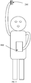
- the user can hold the image capturing device 200 with one hand and the terminal device 100 with the other hand, so the user can capture images at various positions and directions through the image capturing device 200, and view the images through the display screen 120 of the terminal device 100.
- the user may dispose the image capturing device 200 in a certain place, and view the images captured by the image capturing device 200 through the terminal device 100 in another place. Since the image capturing device 200 can be taken out from the terminal device 100 and maintain in communication with the terminal device 100 after being taken out, the terminal device 100 does not need to provide a front camera on the side that the display screen 120 locates, so the screen-to-body ratio of the terminal device 100 can be increased. For example, the screen-to-body ratio of the terminal device 100 with the above structure may be more than 85%. It can be understood that, the arrangement of the locking mechanism 300 can reliably fix the image capturing device 200 in the mounting recess 130 and can prevent the image capturing device 200 from easily falling out of the mounting recess 130. When the locking mechanism 300 releases the locking to the image capturing device 200, the image capturing device 200 can be taken out of the mounting recess 130, thereby facilitating the usage for the user.
- the terminal device 100 is substantially in a shape of cuboid.
- the mobile terminal 10 includes a rear wall 111 and side walls connected to outer peripheries of the display screen 120.
- the rear wall 111 is located at the side facing away from the display area and connected to the side walls.
- the side walls include a left side wall 112, a right side wall 114 opposite to the left side wall 112, a top side wall 116, and a bottom side wall 118 opposite to the top side wall 116.
- Each of the left side wall 112 and the right side wall 114 are located between the top side wall 116 and the bottom side wall 118.
- each of the top side wall 116 and the bottom side wall 118 are located between the left side wall 112 and the right side wall 114.
- the mounting recess 130 penetrates through the rear side wall 111.
- the mounting recess 130 is located between the left side wall 112 and the right side wall 114, and also is located between the top side wall 116 and the bottom side wall 118.
- the mobile terminal 10 is provided with two locking mechanisms 300, one is located adjacent to the left side wall 112, and the other is located adjacent to the right side wall 114.
- the locking mechanism 300 located adjacent to the right side wall 114 is taken as an example for description. However, it can be understood that there may be only one locking mechanism 300 included in the mobile terminal 10.
- the terminal device 100 may further include a middle plate 140, the middle plate 140 is positioned between the display screen 120 and the rear wall 111.
- the resisting member 310 is rotatably connected to the middle plate 140, and the bolt 320 is slidably coupled to the middle plate 140.
- the middle plate 140 can be integrally formed with the side walls, or can be detachably connected with the side walls. Using the middle plate 140 to support the bolt 320 and the resisting member 310 can improve the structural stability of the locking mechanism 300.
- the locking mechanism 300 includes a pressing block 330, which includes a block body 331 and a limit part 333 integrally formed with the block body 331.
- a pressing block 330 which includes a block body 331 and a limit part 333 integrally formed with the block body 331.
- One of the side walls is provided with an installation hole, the block body 331 engages with the installation hole.
- the limit part 333 is positioned between the side wall and the resisting member 310, and the side wall and the resisting member 310 can abut the limit part 333 respectively.
- the pressing block 330 can press the resisting member 310 thereby enabling the resisting member 310 to be rotatable relative to the middle plate 140.
- the user presses the pressing block 330
- the pressing block 330 presses the resisting member 310
- the resisting member 310 rotates relative to the middle plate 140, so that the bolt 320 can be driven to slide relative to the middle plate 140, meanwhile the bolt 320 is enabled to be capable of being exited from the engaging slot 211.
- the pressing block 330 is not necessary in the disclosure.
- the resisting member 310 may protrude out and be exposed from the installation hole, so the bolt 320 can also be exited from the engaging slot 211 when the user pressing the resisting member 310.
- the locking mechanism 300 further includes an elastic member 340.
- One end of the elastic member 340 abuts against the middle plate 140, and the other end of the elastic member 340 abuts against the resisting member 310.
- the elastic member 340 can press the limit part 333 via the resisting member 310, thereby making the limit part 333 abut against one side wall and the block body 331 protrude from an outer surface of said side wall.
- Disposing the elastic member 340 can facilitate the return of the pressing block 330 and the bolt 320, so the bolt 320 can be inserted into or exited from the mounting recess 130, the outer surface of the block body 331 can be protruded from the sidewall to facilitate the user to press the pressing block 330, and thereby facilitating the detachment of the image capturing device 200 from the mounting recess 130.
- the elastic member 340 may be a spring, an elastic piece, an elastic column, or the like.
- the elastic member 340 can be compressed under the pressing of the resisting member 310. When the pressing block 330 is released, the elastic member 340 can push the pressing block 330 back. It can be understood that the elastic member 340 is not necessary in the disclosure, as in an exemplary alternative embodiment, a structure such as a pull rod may be provided to push the resisting member 310 back into position.
- the bolt 320 is provided with a notch 321.
- the resisting member 310 includes a first end 311 and a second end 313.
- the first end 311 abuts against the limit part 333, and the second end 313 is received in the notch 321 and rotatable relative to the bolt 320.
- a cross-section of the second end 313 is arc-shaped, and the second end 313 may be substantially spherical.
- the second end 313 is received in the notch 321 and can rotate relative to the bolt 320, thereby avoiding interference with the sliding of the bolt 320.
- resisting member 310 can also be rotatably connected with the bolt 320 in an engagement form of a rotating shaft with a shaft hole, which will not be detailed here.
- the middle plate 140 is provided with a sliding groove 141, and the bolt 320 is engaged with and partially provided in the sliding groove 141.
- the terminal device 100 further includes a cover plate 150 detachably coupled to the middle plate 140, and the cover plate 150 covers the sliding groove 141.
- the bolt 320 slides in the sliding groove 141, the sliding groove 141 and the cover plate 150 can guide and limit the sliding of the bolt 320, which is beneficial to a smooth movement of the bolt 320.
- Such a structure also facilitates the assembly and disassembly of the cover plate 150 and the middle plate 140.
- the image capturing device 200 is substantially in a shape of a cuboid.
- the casing 210 includes a front end surface 213, a rear end surface 215 opposite to the front end surface 213, and side end surfaces connected between the front end surface 213 and the rear end surface 215.
- the side end surfaces include a left end surface 212, a right end surface 214 opposite to the left end surface 212, a top end surface 216, and a bottom end surface 218 opposite to the top end surface 216.
- Each of the left end surface 212 and the right end surface 214 is located between the top end surface 216 and the bottom end surface 218, and each of the top end surface 216 and the bottom end surface 218 is located between the left end surface 212 and the right end surface 214.
- the light incident surface 221 is exposed on the front end surface 213, and the engaging slot 211 is provided in the left end surface 212 and the right end surface 214.
- the light incident surface 221 protrudes from the front end surface 213.
- the portion that the light incident surface 221 of the image capturing device 200 is located can have a relatively thicker thickness, while other portions of the image capturing device 200 can be made relatively thinner. Therefore, it is beneficial to the lightness and thinness of the image capturing device 200, which in turn is beneficial to the lightness and thinness of the mobile terminal 10.
- the image capturing device 200 may include one or more module contacts, and the terminal device 100 includes one or more device contacts.
- the module contacts can be in contact with the device contacts respectively, so that the terminal device 100 can charge the image capturing device 200.
- Such a structure facilitates the terminal device 100 to charge the image capturing device 200 and is beneficial for the image capturing device 200 to retain sufficient power for the convenience of the user.
- the module contacts and/or the device contacts may be metal contacts, and the module contacts and the device contacts may have various structural forms.
- the image capturing device 200 may define small holes and metal contacts can be respectively installed therein as the module contacts, the terminal device 100 can be provided with protruding metal contacts as the device contacts, thereby realizing the charging of the terminal device 100 to the image capturing device 200 through the cooperation of the module contacts and the device contacts.
- a module main board 240 is provided in the casing 210.
- the front end surface 213 of the casing 210 is provided with a light exit hole 217, and the light incident surface 221 is exposed from the light exit hole 217.
- the second power supply module 230 is stacked on the module main board 240 and can supply power to the module main board 240.
- the module main board 240 can respectively communicate with the camera module 220 and the second wireless communication module.
- the module main board 240 may include a circuit board and a number of electronic components connected to the circuit board.
- the module main board 240 is configured to process image information captured by the camera module 220 and send it to the terminal device 100 through the second wireless communication module.
- the module main board 240 is substantially U-shaped and defines a gap 241 thereby.
- the camera module 220 includes a lens barrel 223, and the lens barrel 223 penetrates the gap 241.
- Such a design can avoid stacking the lens barrel 223 on the module main board 240, thereby making internal components in the image capturing device 200 be more compact arrange, it is beneficial to reduce a thickness of the image capturing device 200.
- the second power supply module 230 is provided with a through hole 221, so the second power supply module 230 is substantially annular.
- the through hole 221 communicates with the gap 241, and the lens barrel 223 penetrates the through hole 221 and the gap 241 thereby receiving in the through hole 221 and the gap 241.
- Such a structure can avoid stacking the lens barrel 223 on the second power supply module 230, thus making the arrangement of internal components in the image capturing device 200 be more compact, and reducing the thickness of the image capturing device 200.
- the first power module and the second power supply module 230 each include a battery that can be repeatedly charged and discharged, such as a lithium battery.
- the first power module and the second power supply module 230 each may also be a fuel cell or other batteries, and the second power supply module 230 may be connected to the module main board 240 through a power flexible printed circuit board, thereby enabling the second power supply module 230 supply power to the module main board 240, and details are not repeated here.
Landscapes
- Engineering & Computer Science (AREA)
- Theoretical Computer Science (AREA)
- Computer Hardware Design (AREA)
- Signal Processing (AREA)
- Human Computer Interaction (AREA)
- Physics & Mathematics (AREA)
- General Engineering & Computer Science (AREA)
- General Physics & Mathematics (AREA)
- Multimedia (AREA)
- Telephone Set Structure (AREA)
- Studio Devices (AREA)
Abstract
Description
- The present disclosure relates to the field of mobile terminal technologies, and more particularly, to a mobile terminal.
- Mobile terminals (phones, tablets, etc.) are generally equipped with cameras, which are configured to provide functions such as video calling and shooting. However, shooting scenarios of the camera are relatively monotonous.
- Based on the above, the disclosure provides a mobile terminal.
- A mobile terminal includes a terminal device, an image capturing device and a locking mechanism.
- The terminal device comprises a display screen, a first power supply module, and a first wireless communication module, wherein the first power supply module is configured to supply power to the display screen and the first wireless communication module, and the terminal device defines a mounting recess on a side thereof facing away from a display area of the display screen.
- The image capturing device comprises a casing, a camera module, a second power supply module, and a second wireless communication module, wherein the second power supply module is configured to supply power to the camera module and the second wireless communication module, the camera module and the second power supply module are arranged in the casing, the camera module has a light incident surface exposed from the casing; the image capturing device is configured to be mounted in the mounting recess, thereby making the light incident surface be exposed on the side facing away from the display area; the casing is provided with an engaging slot.
- The locking mechanism comprises a resisting member and a bolt, wherein the resisting member is rotatably connected to the terminal device and abuts against the bolt; when the image capturing device is mounted in the mounting recess, the resisting member is configured to rotate relative to the terminal device thereby driving the bolt to move to a first position and a second position, the bolt is engaged with the engaging slot and the image capturing device is locked to the terminal device when the bolt is at the first position, the bolt exits from the engaging slot and the image capturing device is detachable from the mounting recess when the bolt is at the second position; the second wireless communication module is communicatively connected with the first wireless communication module after the image capturing device being detached from the mounting recess.
- In some embodiments, the disclosure provides a mobile terminal, including a terminal device, an image capturing device and a locking mechanism.
- The terminal device comprises a display screen, wherein the terminal device defines a mounting recess on the side thereof facing away from a display area of the display screen.
- The image capturing device comprises a casing and a camera module, wherein the camera module is disposed in the casing, the image capturing device is configured to be mounted in the mounting recess, and the camera module is configured to receive ambient lights from the side facing away from the display area, the casing defining an engaging slot.
- The locking mechanism comprises a resisting member and a bolt, wherein the resisting member is rotatably connected to the terminal device and abuts against the bolt; when the image capturing device is mounted in the mounting recess, the resisting member is configured to rotate relative to the terminal device thereby driving the bolt to move to a first position and a second position, the bolt is engaged with the engaging slot and the image capturing device is locked to the terminal device when the bolt is at the first position, the bolt exits from the engaging slot and the image capturing device is detachable from the mounting recess when the bolt is at the second position; the image capturing device is communicatively connected with the terminal device after the image capturing device being detached from the mounting recess.
- In order to more clearly describe the technical solutions of the disclosure, the following briefly introduces the drawings needed to be used in the description of the embodiments. Obviously, the drawings in the following description only illustrate some embodiments of the disclosure, and other drawings can be obtained for those skilled in the art, based on these drawings without any creative work.
-
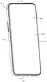
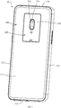
FIG. 1 is a perspective view of a mobile terminal, wherein an image capturing device of the mobile terminal is mounted on a terminal device according to an embodiment; - FI.G. 2 is another perspective view of the mobile terminal as shown in
FIG. 1 , wherein the image capturing device of the mobile terminal is mounted on the terminal device; -
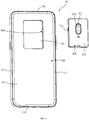
FIG. 3 is a perspective view showing the image capturing device of the mobile terminal shown inFIG. 2 being detached from the terminal device; -
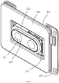
FIG. 4 is an exploded view of the image capturing device of the mobile terminal shown inFIG. 3 ; -
FIG. 5 is a perspective view of the image capturing device of the mobile terminal shown inFIG. 4 after removing a casing; -
FIG. 6 is a front view showing a locking mechanism of the mobile terminal shown inFIG. 2 is at a first position; -
FIG. 7 is an enlarged schematic diagram of the position A of the mobile terminal shown inFIG. 6 ; -
FIG. 8 is a schematic diagram showing an application scene of the imaging capturing device of the mobile terminal shown inFIG. 3 ; -
Fig. 9 is a front view of the locking mechanism of the mobile terminal shown inFIG. 5 being covered with a cover plate. - In order to facilitate the understanding of the disclosure, the following will make a more comprehensive description of the disclosure with reference to the relevant drawings. The drawings illustrate preferred embodiments of the disclosure. However, this disclosure can be implemented in many different manners and is not limited to the following described embodiments. On the contrary, the purpose of providing these embodiments is to make the understanding of the disclosure more thorough and comprehensive.
- The wording "terminal device" refers to, but is not limited to, a device capable of receiving and/or sending communication signals via one or more of the following communicating ways:
- (1) via wired lines, such as Public Switched Telephone Networks (PSTN), Digital Subscriber Lines (DSL), digital cables, and direct cable connections;
- (2) via a wireless interface, such as a cellular network, a Wireless Local Area Network (WLAN), a digital TV network (e.g., DVB-H network), a satellite network, a AM-FM broadcast transmitter.
- A terminal device, which is configured to communicate through a wireless interface, may be referred to as a "mobile terminal". Examples of the mobile terminal include but are not limited to the following electronic devices:
- (1) a satellite phone or a cellular phone;
- (2) Personal Communications System (PCS) terminals, capable of integrating cellular radio telephones, data processing and fax, and data communicating capabilities;
- (3) a radio telephone, a pager, an Internet/Intranet access, a Web browser, a notebook, a calendar, a personal digital assistants (PDA) equipped with a Global Positioning System (GPS) receiver;
- (4) a conventional laptop and/or palmtop receiver;
- (5) a conventional laptop and/or palmtop radio telephone transceiver; etc.
- In the embodiment as illustrated in
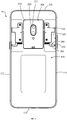
FIG. 1 ,FIG. 2 , andFIG. 3 , amobile terminal 10 is a smart phone. Themobile terminal 10 includes aterminal device 100, an image capturingdevice 200 and alocking mechanism 300. Theterminal device 100 includes adisplay screen 120, a first power supply module, and a first wireless communication module. The first power supply module is configured to supply power to thedisplay screen 120 and the first wireless communication module. Thefirst display screen 120 is configured to display information and provide an interactive interface for a user. Theterminal device 100 defines amounting recess 130 at one side which is facing away a display area of thedisplay screen 120. As illustrated inFIG. 4 andFIG. 5 , the image capturingdevice 200 includes acasing 210, acamera module 220, a secondpower supply module 230, and a second wireless communication module. The secondpower supply module 230 is configured supply power to thecamera module 220 and the second wireless communication module. Thecamera module 220 and the secondpower supply module 230 are arranged in thecasing 210. Thecamera module 220 has alight incident surface 221, which is exposed from thecasing 210. Ambient lights can pass through thelight incident surface 221 and enter into a photosensitive element of thecamera module 220. The image capturingdevice 200 can be installed in themounting recess 130, thereby enabling thelight incident surface 221 to be exposed on the side facing away from the display area of thedisplay screen 120. Thecasing 210 is provided with anengaging slot 211. Referring toFIG. 6 andFIG. 7 , thelocking mechanism 300 includes a resistingmember 310 and abolt 320, and the resistingmember 310 is rotatably connected to theterminal device 100 and abuts against thebolt 320. When the image capturingdevice 200 is installed in themounting recess 130, the resistingmember 310 is capable of rotating relative to theterminal device 100 thereby driving thebolt 320 to move to a first position and a second position. Referring toFIG. 7 , at the first position, thebolt 320 is engaged with theengaging slot 211 and the image capturingdevice 200 is locked to theterminal device 100. At the second position, thebolt 320 exits from theengaging slot 211 and the image capturingdevice 200 is capable of being detached from themounting recess 130. When the image capturingdevice 200 is capable of being detached from themounting recess 130, the second wireless communication module can be communicatively connected with the first wireless communication module, thereby achieving the communication between the image capturingdevice 200 and theterminal device 100. - The first wireless communication module and the second communication module are configured for data transmission between the
terminal device 100 and the image capturingdevice 200. The first wireless communication module and the second wireless communication module may utilize Near Field Communication technology, and the first wireless communication module and the second wireless communication module use the same communication protocol. For example, the first wireless communication module and the second wireless communication module both may be Bluetooth communication modules, or both may be Wireless Fidelity (Wi-Fi) communication modules, or both may be Infrared Data (lrDA) communication modules, or both may be ZigBee communication modules, or both may be Ultra WideBand, or both may be Near Field Communication (NFC) modules, etc. In an alternative embodiment, theterminal device 100 may include a third wireless communication module, which is configured to communicate with an external device such as a base station or anothermobile terminal 10, thereby facilitating communication between more than onemobile terminals 10. - When the image capturing
device 200 is locked in themounting recess 130, the image capturingdevice 200 may communicate with the first wireless communication module by the second wireless communication module, and thecamera module 220 at this time can perform functions as a rear camera. A user can perform remote shooting, video recording and other operations through theimage capturing device 200. When theimage capturing device 200 is detached from the mountingrecess 130, the second wireless communication module can still communicate with the first wireless communication module, and the user at this time can use theimage capturing device 200 to shoot with any direction in any scene. - In the above
mobile terminal 10, theimage capturing device 200 not only can be installed in the mountingrecess 130 but also can be released from the mountingrecess 130. After theimage capturing device 200 is taken out from the mountingrecess 130, theimage capturing device 200 communicates with the first wireless communication module of theterminal device 100 through the second wireless communication module, and the user can use theimage capturing device 200 to shoot in multiple directions and multiple scenarios. In the embodiment as illustrated inFIG. 8 , the user can hold theimage capturing device 200 with one hand and theterminal device 100 with the other hand, so the user can capture images at various positions and directions through theimage capturing device 200, and view the images through thedisplay screen 120 of theterminal device 100. In an alternative embodiment, the user may dispose theimage capturing device 200 in a certain place, and view the images captured by theimage capturing device 200 through theterminal device 100 in another place. Since theimage capturing device 200 can be taken out from theterminal device 100 and maintain in communication with theterminal device 100 after being taken out, theterminal device 100 does not need to provide a front camera on the side that thedisplay screen 120 locates, so the screen-to-body ratio of theterminal device 100 can be increased. For example, the screen-to-body ratio of theterminal device 100 with the above structure may be more than 85%. It can be understood that, the arrangement of thelocking mechanism 300 can reliably fix theimage capturing device 200 in the mountingrecess 130 and can prevent theimage capturing device 200 from easily falling out of the mountingrecess 130. When thelocking mechanism 300 releases the locking to theimage capturing device 200, theimage capturing device 200 can be taken out of the mountingrecess 130, thereby facilitating the usage for the user. - In the embodiments as illustrated in
FIG. 1 andFIG. 2 , theterminal device 100 is substantially in a shape of cuboid. Themobile terminal 10 includes arear wall 111 and side walls connected to outer peripheries of thedisplay screen 120. Therear wall 111 is located at the side facing away from the display area and connected to the side walls. The side walls include aleft side wall 112, aright side wall 114 opposite to theleft side wall 112, atop side wall 116, and abottom side wall 118 opposite to thetop side wall 116. Each of theleft side wall 112 and theright side wall 114 are located between thetop side wall 116 and thebottom side wall 118. Each of thetop side wall 116 and thebottom side wall 118 are located between theleft side wall 112 and theright side wall 114. The mountingrecess 130 penetrates through therear side wall 111. The mountingrecess 130 is located between theleft side wall 112 and theright side wall 114, and also is located between thetop side wall 116 and thebottom side wall 118. In one embodiment, themobile terminal 10 is provided with two lockingmechanisms 300, one is located adjacent to theleft side wall 112, and the other is located adjacent to theright side wall 114. In the following, thelocking mechanism 300 located adjacent to theright side wall 114 is taken as an example for description. However, it can be understood that there may be only onelocking mechanism 300 included in themobile terminal 10. - The
terminal device 100 may further include amiddle plate 140, themiddle plate 140 is positioned between thedisplay screen 120 and therear wall 111. The resistingmember 310 is rotatably connected to themiddle plate 140, and thebolt 320 is slidably coupled to themiddle plate 140. Themiddle plate 140 can be integrally formed with the side walls, or can be detachably connected with the side walls. Using themiddle plate 140 to support thebolt 320 and the resistingmember 310 can improve the structural stability of thelocking mechanism 300. - The
locking mechanism 300 includes apressing block 330, which includes ablock body 331 and alimit part 333 integrally formed with theblock body 331. One of the side walls is provided with an installation hole, theblock body 331 engages with the installation hole. Thelimit part 333 is positioned between the side wall and the resistingmember 310, and the side wall and the resistingmember 310 can abut thelimit part 333 respectively. Thepressing block 330 can press the resistingmember 310 thereby enabling the resistingmember 310 to be rotatable relative to themiddle plate 140. In one embodiment, the user presses thepressing block 330, thepressing block 330 presses the resistingmember 310, and the resistingmember 310 rotates relative to themiddle plate 140, so that thebolt 320 can be driven to slide relative to themiddle plate 140, meanwhile thebolt 320 is enabled to be capable of being exited from the engagingslot 211. It can be understood that thepressing block 330 is not necessary in the disclosure. As an exemplary alternative embodiment, the resistingmember 310 may protrude out and be exposed from the installation hole, so thebolt 320 can also be exited from the engagingslot 211 when the user pressing the resistingmember 310. - In one embodiment, the
locking mechanism 300 further includes anelastic member 340. One end of theelastic member 340 abuts against themiddle plate 140, and the other end of theelastic member 340 abuts against the resistingmember 310. Theelastic member 340 can press thelimit part 333 via the resistingmember 310, thereby making thelimit part 333 abut against one side wall and theblock body 331 protrude from an outer surface of said side wall. Disposing theelastic member 340 can facilitate the return of thepressing block 330 and thebolt 320, so thebolt 320 can be inserted into or exited from the mountingrecess 130, the outer surface of theblock body 331 can be protruded from the sidewall to facilitate the user to press thepressing block 330, and thereby facilitating the detachment of theimage capturing device 200 from the mountingrecess 130. Theelastic member 340 may be a spring, an elastic piece, an elastic column, or the like. Theelastic member 340 can be compressed under the pressing of the resistingmember 310. When thepressing block 330 is released, theelastic member 340 can push thepressing block 330 back. It can be understood that theelastic member 340 is not necessary in the disclosure, as in an exemplary alternative embodiment, a structure such as a pull rod may be provided to push the resistingmember 310 back into position. - As illustrated in
FIG. 7 , thebolt 320 is provided with anotch 321. The resistingmember 310 includes afirst end 311 and asecond end 313. Thefirst end 311 abuts against thelimit part 333, and thesecond end 313 is received in thenotch 321 and rotatable relative to thebolt 320. Specifically, a cross-section of thesecond end 313 is arc-shaped, and thesecond end 313 may be substantially spherical. During the rotation of the resistingmember 310 relative to themiddle plate 140, thesecond end 313 is received in thenotch 321 and can rotate relative to thebolt 320, thereby avoiding interference with the sliding of thebolt 320. Such a structure facilitates the assembly of the resistingmember 310 and thebolt 320. It can be understood that the resistingmember 310 can also be rotatably connected with thebolt 320 in an engagement form of a rotating shaft with a shaft hole, which will not be detailed here. - In one embodiment as illustrated in
FIG. 7 , themiddle plate 140 is provided with a slidinggroove 141, and thebolt 320 is engaged with and partially provided in the slidinggroove 141. Referring toFIG. 9 , theterminal device 100 further includes acover plate 150 detachably coupled to themiddle plate 140, and thecover plate 150 covers the slidinggroove 141. Thebolt 320 slides in the slidinggroove 141, the slidinggroove 141 and thecover plate 150 can guide and limit the sliding of thebolt 320, which is beneficial to a smooth movement of thebolt 320. Such a structure also facilitates the assembly and disassembly of thecover plate 150 and themiddle plate 140. - Referring to
FIG. 4 andFIG. 5 , theimage capturing device 200 is substantially in a shape of a cuboid. Thecasing 210 includes afront end surface 213, arear end surface 215 opposite to thefront end surface 213, and side end surfaces connected between thefront end surface 213 and therear end surface 215. The side end surfaces include aleft end surface 212, aright end surface 214 opposite to theleft end surface 212, atop end surface 216, and abottom end surface 218 opposite to thetop end surface 216. Each of theleft end surface 212 and theright end surface 214 is located between thetop end surface 216 and thebottom end surface 218, and each of thetop end surface 216 and thebottom end surface 218 is located between theleft end surface 212 and theright end surface 214. Thelight incident surface 221 is exposed on thefront end surface 213, and theengaging slot 211 is provided in theleft end surface 212 and theright end surface 214. When theimage capturing device 200 is mounted in the mountingrecess 130, thefront end surface 213 can be flush with an outer surface of therear wall 111. Thus, after theimage capturing device 200 with such a structure is installed in the mountingrecess 130, themobile terminal 10 can maintain a high overall appearance consistency. In one embodiment, thelight incident surface 221 protrudes from thefront end surface 213. With such a structure, the portion that thelight incident surface 221 of theimage capturing device 200 is located, can have a relatively thicker thickness, while other portions of theimage capturing device 200 can be made relatively thinner. Therefore, it is beneficial to the lightness and thinness of theimage capturing device 200, which in turn is beneficial to the lightness and thinness of themobile terminal 10. - As one embodiment, the
image capturing device 200 may include one or more module contacts, and theterminal device 100 includes one or more device contacts. When theimage capturing device 200 is installed in the mountingrecess 130, the module contacts can be in contact with the device contacts respectively, so that theterminal device 100 can charge theimage capturing device 200. Such a structure facilitates theterminal device 100 to charge theimage capturing device 200 and is beneficial for theimage capturing device 200 to retain sufficient power for the convenience of the user. It is understood that the module contacts and/or the device contacts may be metal contacts, and the module contacts and the device contacts may have various structural forms. For example, theimage capturing device 200 may define small holes and metal contacts can be respectively installed therein as the module contacts, theterminal device 100 can be provided with protruding metal contacts as the device contacts, thereby realizing the charging of theterminal device 100 to theimage capturing device 200 through the cooperation of the module contacts and the device contacts. - Referring to
FIG. 4 andFIG. 5 , a modulemain board 240 is provided in thecasing 210. Thefront end surface 213 of thecasing 210 is provided with alight exit hole 217, and thelight incident surface 221 is exposed from thelight exit hole 217. The secondpower supply module 230 is stacked on the modulemain board 240 and can supply power to the modulemain board 240. The modulemain board 240 can respectively communicate with thecamera module 220 and the second wireless communication module. The modulemain board 240 may include a circuit board and a number of electronic components connected to the circuit board. The modulemain board 240 is configured to process image information captured by thecamera module 220 and send it to theterminal device 100 through the second wireless communication module. The modulemain board 240 is substantially U-shaped and defines agap 241 thereby. Thecamera module 220 includes alens barrel 223, and thelens barrel 223 penetrates thegap 241. Such a design can avoid stacking thelens barrel 223 on the modulemain board 240, thereby making internal components in theimage capturing device 200 be more compact arrange, it is beneficial to reduce a thickness of theimage capturing device 200. - Furthermore, the second
power supply module 230 is provided with a throughhole 221, so the secondpower supply module 230 is substantially annular. The throughhole 221 communicates with thegap 241, and thelens barrel 223 penetrates the throughhole 221 and thegap 241 thereby receiving in the throughhole 221 and thegap 241. Such a structure can avoid stacking thelens barrel 223 on the secondpower supply module 230, thus making the arrangement of internal components in theimage capturing device 200 be more compact, and reducing the thickness of theimage capturing device 200. It can be understood that the first power module and the secondpower supply module 230 each include a battery that can be repeatedly charged and discharged, such as a lithium battery. In other embodiments, the first power module and the secondpower supply module 230 each may also be a fuel cell or other batteries, and the secondpower supply module 230 may be connected to the modulemain board 240 through a power flexible printed circuit board, thereby enabling the secondpower supply module 230 supply power to the modulemain board 240, and details are not repeated here. - Technical features of the above-mentioned embodiments can be combined arbitrarily. In order to make the description concise, all possible combinations of the various technical features in the above-mentioned embodiments are not described. However, as long as there is no contradiction in the combination of these technical features, any combination should be considered as the scope of this specification.
- The above-mentioned embodiments only describe several embodiments of the disclosure, and the description is relatively specific and detailed, but it should not be understood as a limitation on the scope of the disclosure. It should be pointed out that for those of ordinary skill in the art, modifications and improvements can be made without departing from the concept of this disclosure, and these should fall within the protection scope of this disclosure. Therefore, the scope of protection of this disclosure shall be subject to the appended claims.
Claims (20)
- A mobile terminal, comprising:a terminal device, comprising a display screen, a first power supply module, and a first wireless communication module, wherein the first power supply module is configured to supply power to the display screen and the first wireless communication module, and the terminal device defines a mounting recess on the side thereof facing away from a display area of the display screen;an image capturing device, comprising a casing, a camera module, a second power supply module, and a second wireless communication module, wherein the second power supply module is configured to supply power to the camera module and the second wireless communication module, the camera module and the second power supply module are disposed in the casing, the camera module has a light incident surface exposed from the casing; the image capturing device is configured to be mounted in the mounting recess, thereby making the light incident surface be exposed on the side facing away from the display area; the casing is provided with an engaging slot; anda locking mechanism, comprising a resisting member and a bolt, wherein the resisting member is rotatably connected to the terminal device and abuts against the bolt; when the image capturing device is mounted in the mounting recess, the resisting member is rotatable relative to the terminal device thereby driving the bolt to move to a first position and a second position, the bolt is engaged with the engaging slot and the image capturing device is locked to the terminal device when the bolt is at the first position, the bolt exits from the engaging slot and the image capturing device is detachable from the mounting recess when the bolt is at the second position; the second wireless communication module is communicatively connected with the first wireless communication module after the image capturing device being detached from the mounting recess.
- The mobile terminal as claimed in claim 1, wherein the terminal device comprises a rear wall and side walls connected to outer peripheries of the display screen, the rear wall is connected with the side walls and located at the side facing away from the display area; the side walls includes a left side wall, a right side wall opposite to the left side wall, a top side wall, and a bottom side wall opposite to the top side wall, the left side wall and the right side wall are both located between the top side wall and the bottom side wall, the top side wall and the bottom side wall are both located between the left side wall and the right side wall; the mounting recess penetrates the rear wall, the mounting recess is located between the left side wall and the right side wall, and the mounting recess is located between the top side wall and the bottom side wall.
- The mobile terminal as claimed in claim 2, wherein the terminal device comprises a middle plate, the middle plate is positioned between the display screen and the rear wall, and the resisting member is rotatably connected to the middle plate, and the bolt is slidably coupled with the middle plate.
- The mobile terminal as claimed in claim 3, wherein the locking mechanism comprises a pressing block, the pressing block comprises a block body and a limit part integrally formed with the block body; one of the side walls is provided with an installation hole, the block body engages with the installation hole; the limit part is positioned between the resisting member and the side wall, the side wall and the resisting member are respectively abut against the limit part, the pressing block presses against the resisting member, thereby enabling the resisting member to be rotatable relative to the middle plate.
- The mobile terminal as claimed in claim 4, wherein the locking mechanism comprises an elastic member, one end of the elastic member abuts against the middle plate, and the other end of the elastic member abuts against the resisting member, the elastic member presses the limit part through the resisting member, thereby making the limit part press against the side wall and making the block body protrude from an outer surface of the side wall.
- The mobile terminal according to claim 4, wherein the bolt is provided with a notch, the resisting member comprises a first end and a second end, the first end abuts against the limit part, and the second end is received in the notch and rotatable relative to the bolt.
- The mobile terminal as claimed in claim 3, wherein the middle plate is provided with a sliding groove, and the bolt engages with the sliding groove, the terminal device comprises a cover plate detachably coupled with the middle plate, and the cover plate covers the sliding groove.
- The mobile terminal as claimed in claim 2, wherein the casing includes a front end surface, a rear end surface opposite to the front end surface, and side end surfaces connected between the front end surface and the rear end surface, the side end surfaces comprises a left end surface, a right end surface opposite to the left end surface, a top end surface, and a bottom end surface opposite to the top end surface, the left end surface and the right end surface are both located between the top end surface and the bottom end surface, the top end surface and the bottom end surface are both located between the left end surface and the right end surface; the light incident surface is exposed on the front end surface, the front end surface is flush with an outer surface of the rear wall when the image capturing device is mounted in the mounting recess.
- The mobile terminal as claimed in claim 1, wherein the image capturing device comprises one or more module contacts, the terminal device comprises one or more device contacts, the module contacts are in contact with the device contacts when the image capturing device is mounted in the mounting recess, thereby charging the image capturing device from the terminal device.
- The mobile terminal according to claim 1, wherein the image capturing device comprises a module main board disposed in the casing, the second power supply module is stacked on the module main board and configured to supply power for the module main board, the module main board respectively communicates with the camera module and the second wireless communication module; the module main board is U-shaped and defines a gap thereby, the camera module comprises a lens barrel, and the lens barrel engages with the gap.
- The mobile terminal as claimed in claim 10, wherein the second power supply module is provided with a through hole, the through hole communicates with the gap, and the lens barrel engages with the through hole.
- The mobile terminal as claimed in claim 1, wherein the first wireless communication module and the second wireless communication module are both Bluetooth communication modules, WiFi communication modules, ZigBee communication modules, or NFC communication modules.
- A mobile terminal, comprising:a terminal device, comprising a display screen, wherein the terminal device defines a mounting recess on the side thereof facing away from a display area of the display screen;an image capturing device, comprising a casing and a camera module, wherein the camera module is disposed in the casing, the image capturing device is configured to be mounted in the mounting recess, and the camera module is configured to receive ambient lights from the side facing away from the display area, the casing defining an engaging slot; anda locking mechanism, comprising a resisting member and a bolt, wherein the resisting member is rotatably connected to the terminal device and abuts against the bolt; when the image capturing device is mounted in the mounting recess, the resisting member is configured to rotate relative to the terminal device thereby driving the bolt to move to a first position and a second position, the bolt is engaged with the engaging slot and the image capturing device is locked to the terminal device when the bolt is at the first position, the bolt exits from the engaging slot and the image capturing device is detachable from the mounting recess when the bolt is at the second position; the image capturing device is communicatively connected with the terminal device after the image capturing device being detached from the mounting recess.
- The mobile terminal according to claim 13, wherein the terminal device comprises a rear wall and side walls connected to outer peripheries of the display screen, the rear wall is connected with the side walls and located at the side facing away from the display area; the side walls includes a left side wall, a right side wall opposite to the left side wall, a top side wall, and a bottom side opposite to the top side wall, the left side wall and the right side wall are both located between the top side wall and the bottom side wall, the top side wall and the bottom side wall are both located between the left side wall and the right side wall; the mounting recess penetrates the rear wall, the mounting recess is located between the left side wall and the right side wall, and the mounting recess is located between the top side wall and the bottom side wall.
- The mobile terminal according to claim 14, wherein the terminal device comprises a middle plate, the middle plate is positioned between the display screen and the rear wall, and the resisting member is rotatably connected to the middle plate, and the bolt is slidably couple with the middle plate.
- The mobile terminal according to claim 15, wherein the locking mechanism comprises a pressing block, the pressing block comprises a block body and a limit part integrally formed with the block body; one of the side walls is provided with an installation hole, the block body engages with the installation hole; the limit part is positioned between the resisting member and the side wall, the side wall and the resisting member are respectively abut against the limit part, the pressing block presses against the resisting member, thereby enabling the resisting member is rotatable relative to the middle plate.
- The mobile terminal according to claim 16, wherein the locking mechanism comprises an elastic member, one end of the elastic member abuts the middle plate, and the other end of the elastic member abuts the resisting member, the elastic member presses the limit part through the resisting member, thereby making the limit part press against the side wall and the block body protrude from an outer surface of the side wall.
- The mobile terminal according to claim 16, wherein the bolt is provided with a notch, the resisting member comprises a first end and a second end, the first end abuts against the limit part, and the second end is received in the notch and rotatable relative to the bolt.
- The mobile terminal according to claim 15, wherein the middle plate is provided with a sliding groove, and the bolt engages with the sliding groove, the terminal device comprises a cover plate detachably coupled with the middle plate, and the cover plate covers the sliding groove.
- The mobile terminal according to any one of claims 14-19, wherein the terminal device comprises a first power supply module and a first wireless communication module, the first power module is configured to supply power for the display screen and the first wireless communication module, the image capturing device comprises a second power supply module and a second wireless communication module, the second power supply module is configured to supply power for the camera module and the second wireless communication module, the second power supply module is arranged in the casing; the image capturing device is communicatively connected with the terminal device through the communication between the second wireless communication module and the first wireless communication module.
Applications Claiming Priority (2)
| Application Number | Priority Date | Filing Date | Title |
|---|---|---|---|
| CN201821459213.0U CN209642719U (en) | 2018-09-06 | 2018-09-06 | mobile terminal |
| PCT/CN2019/095800 WO2020048233A1 (en) | 2018-09-06 | 2019-07-12 | Mobile terminal |
Publications (3)
| Publication Number | Publication Date |
|---|---|
| EP3849162A1 true EP3849162A1 (en) | 2021-07-14 |
| EP3849162A4 EP3849162A4 (en) | 2021-10-27 |
| EP3849162B1 EP3849162B1 (en) | 2023-02-15 |
Family
ID=68473067
Family Applications (1)
| Application Number | Title | Priority Date | Filing Date |
|---|---|---|---|
| EP19857431.1A Active EP3849162B1 (en) | 2018-09-06 | 2019-07-12 | Mobile terminal |
Country Status (4)
| Country | Link |
|---|---|
| US (1) | US20210195006A1 (en) |
| EP (1) | EP3849162B1 (en) |
| CN (1) | CN209642719U (en) |
| WO (1) | WO2020048233A1 (en) |
Families Citing this family (3)
| Publication number | Priority date | Publication date | Assignee | Title |
|---|---|---|---|---|
| US11303790B1 (en) * | 2020-12-12 | 2022-04-12 | John G. Posa | Electronic binocular modules adapted for attachment to smartphones and cases therefor |
| CN116801081A (en) * | 2022-03-14 | 2023-09-22 | 英业达科技有限公司 | camera structure |
| EP4390511A4 (en) * | 2022-11-07 | 2025-01-01 | Samsung Electronics Co., Ltd. | PORTABLE ELECTRONIC DEVICE WITH CAMERA MODULE |
Family Cites Families (10)
| Publication number | Priority date | Publication date | Assignee | Title |
|---|---|---|---|---|
| JP2758283B2 (en) * | 1991-06-17 | 1998-05-28 | 株式会社東芝 | Hard disk pack detachable mechanism |
| KR100608727B1 (en) * | 2003-12-09 | 2006-08-04 | 엘지전자 주식회사 | Separate mobile terminal for video call and communication method thereof |
| KR101030426B1 (en) * | 2004-08-24 | 2011-04-20 | 삼성전자주식회사 | Battery pack locking device for portable terminals |
| JP2006321454A (en) * | 2005-05-20 | 2006-11-30 | Yamaha Motor Co Ltd | Vehicle control device for saddle riding type vehicle |
| KR20150064955A (en) * | 2013-12-04 | 2015-06-12 | 엘지전자 주식회사 | Mobile terminal |
| CN104124571B (en) * | 2014-07-22 | 2016-04-20 | 苏州佳世达电通有限公司 | The ejecting mechanism of composite aircraft and apply machine tool and the composite aircraft of this ejecting mechanism |
| CN104363316B (en) * | 2014-11-06 | 2018-03-27 | 广东欧珀移动通信有限公司 | Mobile terminal |
| KR102468129B1 (en) * | 2016-06-01 | 2022-11-22 | 삼성전자주식회사 | Electronic device and manufacturing method thereof |
| CN206413044U (en) * | 2016-12-25 | 2017-08-15 | 北京沃凡思智选家居科技有限公司 | mobile phone with camera unit |
| WO2019228333A1 (en) * | 2018-05-31 | 2019-12-05 | Oppo广东移动通信有限公司 | Camera module and mobile terminal |
-
2018
- 2018-09-06 CN CN201821459213.0U patent/CN209642719U/en not_active Expired - Fee Related
-
2019
- 2019-07-12 WO PCT/CN2019/095800 patent/WO2020048233A1/en not_active Ceased
- 2019-07-12 EP EP19857431.1A patent/EP3849162B1/en active Active
-
2021
- 2021-03-05 US US17/193,673 patent/US20210195006A1/en not_active Abandoned
Also Published As
| Publication number | Publication date |
|---|---|
| EP3849162B1 (en) | 2023-02-15 |
| US20210195006A1 (en) | 2021-06-24 |
| WO2020048233A1 (en) | 2020-03-12 |
| EP3849162A4 (en) | 2021-10-27 |
| CN209642719U (en) | 2019-11-15 |
Similar Documents
| Publication | Publication Date | Title |
|---|---|---|
| CN110557470B (en) | Mobile Terminal | |
| US20210195006A1 (en) | Mobile terminal | |
| WO2019228380A1 (en) | Camera module and mobile terminal | |
| WO2019242480A1 (en) | Electronic device, and control method and apparatus therefor | |
| EP3620891A1 (en) | Mobile terminal with rotatable camera module | |
| US20210195005A1 (en) | Mobile Terminal and Photographing System | |
| CN110557468B (en) | Mobile terminal | |
| CN208836186U (en) | electronic device | |
| CN208890847U (en) | mobile terminal | |
| CN208987022U (en) | Mobile terminal | |
| CN110557472B (en) | Mobile Terminal | |
| CN209390166U (en) | Image acquisition equipment and electronic devices | |
| CN110557469B (en) | Mobile Terminal | |
| CN209105258U (en) | Protective case and mobile terminal assembly | |
| CN111433685B (en) | Watch modules, watches, electronic equipment, electronic devices and mobile terminals | |
| CN110557467B (en) | Image acquisition equipment and electronic devices | |
| CN210041886U (en) | electronic device | |
| CN209517206U (en) | Mobile terminal and image capture device | |
| CN209218200U (en) | Mobile terminal and image acquisition module | |
| CN209497511U (en) | Mobile terminal | |
| CN209572030U (en) | mobile terminal | |
| CN209134462U (en) | Mobile terminal | |
| CN209134461U (en) | Mobile terminal | |
| WO2019228383A1 (en) | Image acquisition apparatus and electronic device | |
| CN111512615B (en) | electronic device |
Legal Events
| Date | Code | Title | Description |
|---|---|---|---|
| STAA | Information on the status of an ep patent application or granted ep patent |
Free format text: STATUS: THE INTERNATIONAL PUBLICATION HAS BEEN MADE |
|
| PUAI | Public reference made under article 153(3) epc to a published international application that has entered the european phase |
Free format text: ORIGINAL CODE: 0009012 |
|
| STAA | Information on the status of an ep patent application or granted ep patent |
Free format text: STATUS: REQUEST FOR EXAMINATION WAS MADE |
|
| 17P | Request for examination filed |
Effective date: 20210406 |
|
| AK | Designated contracting states |
Kind code of ref document: A1 Designated state(s): AL AT BE BG CH CY CZ DE DK EE ES FI FR GB GR HR HU IE IS IT LI LT LU LV MC MK MT NL NO PL PT RO RS SE SI SK SM TR |
|
| A4 | Supplementary search report drawn up and despatched |
Effective date: 20210923 |
|
| RIC1 | Information provided on ipc code assigned before grant |
Ipc: H04M 1/72412 20210101ALN20210917BHEP Ipc: G08C 17/02 20060101ALI20210917BHEP Ipc: H04N 5/225 20060101ALI20210917BHEP Ipc: G06F 1/16 20060101ALI20210917BHEP Ipc: H04M 1/02 20060101AFI20210917BHEP |
|
| DAV | Request for validation of the european patent (deleted) | ||
| DAX | Request for extension of the european patent (deleted) | ||
| GRAP | Despatch of communication of intention to grant a patent |
Free format text: ORIGINAL CODE: EPIDOSNIGR1 |
|
| STAA | Information on the status of an ep patent application or granted ep patent |
Free format text: STATUS: GRANT OF PATENT IS INTENDED |
|
| RIC1 | Information provided on ipc code assigned before grant |
Ipc: H04M 1/72412 20210101ALN20221031BHEP Ipc: G08C 17/02 20060101ALI20221031BHEP Ipc: H04N 5/225 20060101ALI20221031BHEP Ipc: G06F 1/16 20060101ALI20221031BHEP Ipc: H04M 1/02 20060101AFI20221031BHEP |
|
| RIC1 | Information provided on ipc code assigned before grant |
Ipc: H04M 1/72412 20210101ALN20221111BHEP Ipc: G08C 17/02 20060101ALI20221111BHEP Ipc: H04N 5/225 20060101ALI20221111BHEP Ipc: G06F 1/16 20060101ALI20221111BHEP Ipc: H04M 1/02 20060101AFI20221111BHEP |
|
| INTG | Intention to grant announced |
Effective date: 20221201 |
|
| GRAS | Grant fee paid |
Free format text: ORIGINAL CODE: EPIDOSNIGR3 |
|
| GRAA | (expected) grant |
Free format text: ORIGINAL CODE: 0009210 |
|
| STAA | Information on the status of an ep patent application or granted ep patent |
Free format text: STATUS: THE PATENT HAS BEEN GRANTED |
|
| AK | Designated contracting states |
Kind code of ref document: B1 Designated state(s): AL AT BE BG CH CY CZ DE DK EE ES FI FR GB GR HR HU IE IS IT LI LT LU LV MC MK MT NL NO PL PT RO RS SE SI SK SM TR |
|
| REG | Reference to a national code |
Ref country code: CH Ref legal event code: EP Ref country code: GB Ref legal event code: FG4D |
|
| REG | Reference to a national code |
Ref country code: DE Ref legal event code: R096 Ref document number: 602019025370 Country of ref document: DE |
|
| REG | Reference to a national code |
Ref country code: AT Ref legal event code: REF Ref document number: 1548856 Country of ref document: AT Kind code of ref document: T Effective date: 20230315 Ref country code: IE Ref legal event code: FG4D |
|
| REG | Reference to a national code |
Ref country code: LT Ref legal event code: MG9D |
|
| P01 | Opt-out of the competence of the unified patent court (upc) registered |
Effective date: 20230412 |
|
| REG | Reference to a national code |
Ref country code: NL Ref legal event code: MP Effective date: 20230215 |
|
| REG | Reference to a national code |
Ref country code: AT Ref legal event code: MK05 Ref document number: 1548856 Country of ref document: AT Kind code of ref document: T Effective date: 20230215 |
|
| PG25 | Lapsed in a contracting state [announced via postgrant information from national office to epo] |
Ref country code: RS Free format text: LAPSE BECAUSE OF FAILURE TO SUBMIT A TRANSLATION OF THE DESCRIPTION OR TO PAY THE FEE WITHIN THE PRESCRIBED TIME-LIMIT Effective date: 20230215 Ref country code: PT Free format text: LAPSE BECAUSE OF FAILURE TO SUBMIT A TRANSLATION OF THE DESCRIPTION OR TO PAY THE FEE WITHIN THE PRESCRIBED TIME-LIMIT Effective date: 20230615 Ref country code: NO Free format text: LAPSE BECAUSE OF FAILURE TO SUBMIT A TRANSLATION OF THE DESCRIPTION OR TO PAY THE FEE WITHIN THE PRESCRIBED TIME-LIMIT Effective date: 20230515 Ref country code: NL Free format text: LAPSE BECAUSE OF FAILURE TO SUBMIT A TRANSLATION OF THE DESCRIPTION OR TO PAY THE FEE WITHIN THE PRESCRIBED TIME-LIMIT Effective date: 20230215 Ref country code: LV Free format text: LAPSE BECAUSE OF FAILURE TO SUBMIT A TRANSLATION OF THE DESCRIPTION OR TO PAY THE FEE WITHIN THE PRESCRIBED TIME-LIMIT Effective date: 20230215 Ref country code: LT Free format text: LAPSE BECAUSE OF FAILURE TO SUBMIT A TRANSLATION OF THE DESCRIPTION OR TO PAY THE FEE WITHIN THE PRESCRIBED TIME-LIMIT Effective date: 20230215 Ref country code: HR Free format text: LAPSE BECAUSE OF FAILURE TO SUBMIT A TRANSLATION OF THE DESCRIPTION OR TO PAY THE FEE WITHIN THE PRESCRIBED TIME-LIMIT Effective date: 20230215 Ref country code: ES Free format text: LAPSE BECAUSE OF FAILURE TO SUBMIT A TRANSLATION OF THE DESCRIPTION OR TO PAY THE FEE WITHIN THE PRESCRIBED TIME-LIMIT Effective date: 20230215 Ref country code: AT Free format text: LAPSE BECAUSE OF FAILURE TO SUBMIT A TRANSLATION OF THE DESCRIPTION OR TO PAY THE FEE WITHIN THE PRESCRIBED TIME-LIMIT Effective date: 20230215 |
|
| PG25 | Lapsed in a contracting state [announced via postgrant information from national office to epo] |
Ref country code: SE Free format text: LAPSE BECAUSE OF FAILURE TO SUBMIT A TRANSLATION OF THE DESCRIPTION OR TO PAY THE FEE WITHIN THE PRESCRIBED TIME-LIMIT Effective date: 20230215 Ref country code: PL Free format text: LAPSE BECAUSE OF FAILURE TO SUBMIT A TRANSLATION OF THE DESCRIPTION OR TO PAY THE FEE WITHIN THE PRESCRIBED TIME-LIMIT Effective date: 20230215 Ref country code: IS Free format text: LAPSE BECAUSE OF FAILURE TO SUBMIT A TRANSLATION OF THE DESCRIPTION OR TO PAY THE FEE WITHIN THE PRESCRIBED TIME-LIMIT Effective date: 20230615 Ref country code: GR Free format text: LAPSE BECAUSE OF FAILURE TO SUBMIT A TRANSLATION OF THE DESCRIPTION OR TO PAY THE FEE WITHIN THE PRESCRIBED TIME-LIMIT Effective date: 20230516 Ref country code: FI Free format text: LAPSE BECAUSE OF FAILURE TO SUBMIT A TRANSLATION OF THE DESCRIPTION OR TO PAY THE FEE WITHIN THE PRESCRIBED TIME-LIMIT Effective date: 20230215 |
|
| PG25 | Lapsed in a contracting state [announced via postgrant information from national office to epo] |
Ref country code: SM Free format text: LAPSE BECAUSE OF FAILURE TO SUBMIT A TRANSLATION OF THE DESCRIPTION OR TO PAY THE FEE WITHIN THE PRESCRIBED TIME-LIMIT Effective date: 20230215 Ref country code: RO Free format text: LAPSE BECAUSE OF FAILURE TO SUBMIT A TRANSLATION OF THE DESCRIPTION OR TO PAY THE FEE WITHIN THE PRESCRIBED TIME-LIMIT Effective date: 20230215 Ref country code: EE Free format text: LAPSE BECAUSE OF FAILURE TO SUBMIT A TRANSLATION OF THE DESCRIPTION OR TO PAY THE FEE WITHIN THE PRESCRIBED TIME-LIMIT Effective date: 20230215 Ref country code: DK Free format text: LAPSE BECAUSE OF FAILURE TO SUBMIT A TRANSLATION OF THE DESCRIPTION OR TO PAY THE FEE WITHIN THE PRESCRIBED TIME-LIMIT Effective date: 20230215 Ref country code: CZ Free format text: LAPSE BECAUSE OF FAILURE TO SUBMIT A TRANSLATION OF THE DESCRIPTION OR TO PAY THE FEE WITHIN THE PRESCRIBED TIME-LIMIT Effective date: 20230215 |
|
| REG | Reference to a national code |
Ref country code: DE Ref legal event code: R097 Ref document number: 602019025370 Country of ref document: DE |
|
| PG25 | Lapsed in a contracting state [announced via postgrant information from national office to epo] |
Ref country code: SK Free format text: LAPSE BECAUSE OF FAILURE TO SUBMIT A TRANSLATION OF THE DESCRIPTION OR TO PAY THE FEE WITHIN THE PRESCRIBED TIME-LIMIT Effective date: 20230215 |
|
| PLBE | No opposition filed within time limit |
Free format text: ORIGINAL CODE: 0009261 |
|
| STAA | Information on the status of an ep patent application or granted ep patent |
Free format text: STATUS: NO OPPOSITION FILED WITHIN TIME LIMIT |
|
| 26N | No opposition filed |
Effective date: 20231116 |
|
| PG25 | Lapsed in a contracting state [announced via postgrant information from national office to epo] |
Ref country code: SI Free format text: LAPSE BECAUSE OF FAILURE TO SUBMIT A TRANSLATION OF THE DESCRIPTION OR TO PAY THE FEE WITHIN THE PRESCRIBED TIME-LIMIT Effective date: 20230215 |
|
| REG | Reference to a national code |
Ref country code: DE Ref legal event code: R119 Ref document number: 602019025370 Country of ref document: DE |
|
| PG25 | Lapsed in a contracting state [announced via postgrant information from national office to epo] |
Ref country code: MC Free format text: LAPSE BECAUSE OF FAILURE TO SUBMIT A TRANSLATION OF THE DESCRIPTION OR TO PAY THE FEE WITHIN THE PRESCRIBED TIME-LIMIT Effective date: 20230215 |
|
| PG25 | Lapsed in a contracting state [announced via postgrant information from national office to epo] |
Ref country code: MC Free format text: LAPSE BECAUSE OF FAILURE TO SUBMIT A TRANSLATION OF THE DESCRIPTION OR TO PAY THE FEE WITHIN THE PRESCRIBED TIME-LIMIT Effective date: 20230215 |
|
| REG | Reference to a national code |
Ref country code: CH Ref legal event code: PL |
|
| REG | Reference to a national code |
Ref country code: BE Ref legal event code: MM Effective date: 20230731 |
|
| PG25 | Lapsed in a contracting state [announced via postgrant information from national office to epo] |
Ref country code: LU Free format text: LAPSE BECAUSE OF NON-PAYMENT OF DUE FEES Effective date: 20230712 |
|
| GBPC | Gb: european patent ceased through non-payment of renewal fee |
Effective date: 20230712 |
|
| PG25 | Lapsed in a contracting state [announced via postgrant information from national office to epo] |
Ref country code: LU Free format text: LAPSE BECAUSE OF NON-PAYMENT OF DUE FEES Effective date: 20230712 |
|
| REG | Reference to a national code |
Ref country code: IE Ref legal event code: MM4A |
|
| PG25 | Lapsed in a contracting state [announced via postgrant information from national office to epo] |
Ref country code: DE Free format text: LAPSE BECAUSE OF NON-PAYMENT OF DUE FEES Effective date: 20240201 Ref country code: CH Free format text: LAPSE BECAUSE OF NON-PAYMENT OF DUE FEES Effective date: 20230731 Ref country code: GB Free format text: LAPSE BECAUSE OF NON-PAYMENT OF DUE FEES Effective date: 20230712 |
|
| PG25 | Lapsed in a contracting state [announced via postgrant information from national office to epo] |
Ref country code: IT Free format text: LAPSE BECAUSE OF FAILURE TO SUBMIT A TRANSLATION OF THE DESCRIPTION OR TO PAY THE FEE WITHIN THE PRESCRIBED TIME-LIMIT Effective date: 20230215 Ref country code: FR Free format text: LAPSE BECAUSE OF NON-PAYMENT OF DUE FEES Effective date: 20230731 Ref country code: BE Free format text: LAPSE BECAUSE OF NON-PAYMENT OF DUE FEES Effective date: 20230731 |
|
| PG25 | Lapsed in a contracting state [announced via postgrant information from national office to epo] |
Ref country code: IE Free format text: LAPSE BECAUSE OF NON-PAYMENT OF DUE FEES Effective date: 20230712 |
|
| PG25 | Lapsed in a contracting state [announced via postgrant information from national office to epo] |
Ref country code: IE Free format text: LAPSE BECAUSE OF NON-PAYMENT OF DUE FEES Effective date: 20230712 |
|
| PG25 | Lapsed in a contracting state [announced via postgrant information from national office to epo] |
Ref country code: BG Free format text: LAPSE BECAUSE OF FAILURE TO SUBMIT A TRANSLATION OF THE DESCRIPTION OR TO PAY THE FEE WITHIN THE PRESCRIBED TIME-LIMIT Effective date: 20230215 |
|
| PG25 | Lapsed in a contracting state [announced via postgrant information from national office to epo] |
Ref country code: BG Free format text: LAPSE BECAUSE OF FAILURE TO SUBMIT A TRANSLATION OF THE DESCRIPTION OR TO PAY THE FEE WITHIN THE PRESCRIBED TIME-LIMIT Effective date: 20230215 |
|
| PG25 | Lapsed in a contracting state [announced via postgrant information from national office to epo] |
Ref country code: CY Free format text: LAPSE BECAUSE OF FAILURE TO SUBMIT A TRANSLATION OF THE DESCRIPTION OR TO PAY THE FEE WITHIN THE PRESCRIBED TIME-LIMIT; INVALID AB INITIO Effective date: 20190712 |
|
| PG25 | Lapsed in a contracting state [announced via postgrant information from national office to epo] |
Ref country code: HU Free format text: LAPSE BECAUSE OF FAILURE TO SUBMIT A TRANSLATION OF THE DESCRIPTION OR TO PAY THE FEE WITHIN THE PRESCRIBED TIME-LIMIT; INVALID AB INITIO Effective date: 20190712 |
|
| PG25 | Lapsed in a contracting state [announced via postgrant information from national office to epo] |
Ref country code: TR Free format text: LAPSE BECAUSE OF FAILURE TO SUBMIT A TRANSLATION OF THE DESCRIPTION OR TO PAY THE FEE WITHIN THE PRESCRIBED TIME-LIMIT Effective date: 20230215 |