EP3849058A1 - Phase to phase terminal lead protection - Google Patents
Phase to phase terminal lead protection Download PDFInfo
- Publication number
- EP3849058A1 EP3849058A1 EP21150610.0A EP21150610A EP3849058A1 EP 3849058 A1 EP3849058 A1 EP 3849058A1 EP 21150610 A EP21150610 A EP 21150610A EP 3849058 A1 EP3849058 A1 EP 3849058A1
- Authority
- EP
- European Patent Office
- Prior art keywords
- pair
- terminal leads
- insulative sleeve
- terminal
- recited
- Prior art date
- Legal status (The legal status is an assumption and is not a legal conclusion. Google has not performed a legal analysis and makes no representation as to the accuracy of the status listed.)
- Pending
Links
Images

Classifications
-
- H—ELECTRICITY
- H02—GENERATION; CONVERSION OR DISTRIBUTION OF ELECTRIC POWER
- H02K—DYNAMO-ELECTRIC MACHINES
- H02K5/00—Casings; Enclosures; Supports
- H02K5/04—Casings or enclosures characterised by the shape, form or construction thereof
- H02K5/22—Auxiliary parts of casings not covered by groups H02K5/06-H02K5/20, e.g. shaped to form connection boxes or terminal boxes
- H02K5/225—Terminal boxes or connection arrangements
-
- H—ELECTRICITY
- H02—GENERATION; CONVERSION OR DISTRIBUTION OF ELECTRIC POWER
- H02K—DYNAMO-ELECTRIC MACHINES
- H02K15/00—Processes or apparatus specially adapted for manufacturing, assembling, maintaining or repairing of dynamo-electric machines
- H02K15/30—Manufacture of winding connections
- H02K15/33—Connecting winding sections; Forming leads; Connecting leads to terminals
-
- H—ELECTRICITY
- H01—ELECTRIC ELEMENTS
- H01R—ELECTRICALLY-CONDUCTIVE CONNECTIONS; STRUCTURAL ASSOCIATIONS OF A PLURALITY OF MUTUALLY-INSULATED ELECTRICAL CONNECTING ELEMENTS; COUPLING DEVICES; CURRENT COLLECTORS
- H01R4/00—Electrically-conductive connections between two or more conductive members in direct contact, i.e. touching one another; Means for effecting or maintaining such contact; Electrically-conductive connections having two or more spaced connecting locations for conductors and using contact members penetrating insulation
- H01R4/02—Soldered or welded connections
-
- H—ELECTRICITY
- H01—ELECTRIC ELEMENTS
- H01R—ELECTRICALLY-CONDUCTIVE CONNECTIONS; STRUCTURAL ASSOCIATIONS OF A PLURALITY OF MUTUALLY-INSULATED ELECTRICAL CONNECTING ELEMENTS; COUPLING DEVICES; CURRENT COLLECTORS
- H01R4/00—Electrically-conductive connections between two or more conductive members in direct contact, i.e. touching one another; Means for effecting or maintaining such contact; Electrically-conductive connections having two or more spaced connecting locations for conductors and using contact members penetrating insulation
- H01R4/70—Insulation of connections
-
- H—ELECTRICITY
- H01—ELECTRIC ELEMENTS
- H01R—ELECTRICALLY-CONDUCTIVE CONNECTIONS; STRUCTURAL ASSOCIATIONS OF A PLURALITY OF MUTUALLY-INSULATED ELECTRICAL CONNECTING ELEMENTS; COUPLING DEVICES; CURRENT COLLECTORS
- H01R43/00—Apparatus or processes specially adapted for manufacturing, assembling, maintaining, or repairing of line connectors or current collectors or for joining electric conductors
- H01R43/005—Apparatus or processes specially adapted for manufacturing, assembling, maintaining, or repairing of line connectors or current collectors or for joining electric conductors for making dustproof, splashproof, drip-proof, waterproof, or flameproof connection, coupling, or casing
-
- H—ELECTRICITY
- H01—ELECTRIC ELEMENTS
- H01R—ELECTRICALLY-CONDUCTIVE CONNECTIONS; STRUCTURAL ASSOCIATIONS OF A PLURALITY OF MUTUALLY-INSULATED ELECTRICAL CONNECTING ELEMENTS; COUPLING DEVICES; CURRENT COLLECTORS
- H01R43/00—Apparatus or processes specially adapted for manufacturing, assembling, maintaining, or repairing of line connectors or current collectors or for joining electric conductors
- H01R43/02—Apparatus or processes specially adapted for manufacturing, assembling, maintaining, or repairing of line connectors or current collectors or for joining electric conductors for soldered or welded connections
-
- H—ELECTRICITY
- H01—ELECTRIC ELEMENTS
- H01R—ELECTRICALLY-CONDUCTIVE CONNECTIONS; STRUCTURAL ASSOCIATIONS OF A PLURALITY OF MUTUALLY-INSULATED ELECTRICAL CONNECTING ELEMENTS; COUPLING DEVICES; CURRENT COLLECTORS
- H01R43/00—Apparatus or processes specially adapted for manufacturing, assembling, maintaining, or repairing of line connectors or current collectors or for joining electric conductors
- H01R43/033—Apparatus or processes specially adapted for manufacturing, assembling, maintaining, or repairing of line connectors or current collectors or for joining electric conductors for wrapping or unwrapping wire connections
-
- H—ELECTRICITY
- H01—ELECTRIC ELEMENTS
- H01R—ELECTRICALLY-CONDUCTIVE CONNECTIONS; STRUCTURAL ASSOCIATIONS OF A PLURALITY OF MUTUALLY-INSULATED ELECTRICAL CONNECTING ELEMENTS; COUPLING DEVICES; CURRENT COLLECTORS
- H01R9/00—Structural associations of a plurality of mutually-insulated electrical connecting elements, e.g. terminal strips or terminal blocks; Terminals or binding posts mounted upon a base or in a case; Bases therefor
- H01R9/22—Bases, e.g. strip, block, panel
- H01R9/24—Terminal blocks
-
- H—ELECTRICITY
- H02—GENERATION; CONVERSION OR DISTRIBUTION OF ELECTRIC POWER
- H02K—DYNAMO-ELECTRIC MACHINES
- H02K3/00—Details of windings
- H02K3/32—Windings characterised by the shape, form or construction of the insulation
- H02K3/38—Windings characterised by the shape, form or construction of the insulation around winding heads, equalising connectors, or connections thereto
-
- H—ELECTRICITY
- H02—GENERATION; CONVERSION OR DISTRIBUTION OF ELECTRIC POWER
- H02K—DYNAMO-ELECTRIC MACHINES
- H02K3/00—Details of windings
- H02K3/46—Fastening of windings on the stator or rotor structure
- H02K3/50—Fastening of winding heads, equalising connectors, or connections thereto
-
- H—ELECTRICITY
- H01—ELECTRIC ELEMENTS
- H01R—ELECTRICALLY-CONDUCTIVE CONNECTIONS; STRUCTURAL ASSOCIATIONS OF A PLURALITY OF MUTUALLY-INSULATED ELECTRICAL CONNECTING ELEMENTS; COUPLING DEVICES; CURRENT COLLECTORS
- H01R2201/00—Connectors or connections adapted for particular applications
- H01R2201/10—Connectors or connections adapted for particular applications for dynamoelectric machines
-
- H—ELECTRICITY
- H02—GENERATION; CONVERSION OR DISTRIBUTION OF ELECTRIC POWER
- H02K—DYNAMO-ELECTRIC MACHINES
- H02K2203/00—Specific aspects not provided for in the other groups of this subclass relating to the windings
- H02K2203/06—Machines characterised by the wiring leads, i.e. conducting wires for connecting the winding terminations
Definitions
- the present disclosure relates to electric machines, and more particularly to phase to phase terminal lead protection for electric machines.
- Electric machines such as generators can have brazed terminal leads.
- FOD foreign object debris
- Electric machines such as generators can have brazed terminal leads.
- FOD foreign object debris
- a system includes a pair of terminal leads joined together.
- An insulative sleeve is wrapped around the pair of terminal leads. Lacing binds around the insulative sleeve. Cured epoxy can encase the insulative sleeve and lacing.
- the insulative sleeve can include fiberglass. The insulative sleeve can be wrapped more than 360° around the pair of terminal leads so that a first edge of the insulative sleeve is tucked under a second edge of the insulative sleeve.
- the pair of terminal leads can be brazed together.
- the terminal leads can be mounted to a terminal block.
- the pair of terminal leads can be a single pair of terminal leads.
- One or more additional pairs of terminal leads can be mounted to the terminal block, wherein each additional pair of terminal leads has a respective insulative sleeve wrapped around it.
- the terminal block can be mounted to an electric machine housing.
- the pair of terminal leads can be electrically connected to a stator of the electric machine.
- a method includes brazing together a pair of terminal leads and wrapping the pair of terminal leads in an insulative sleeve after brazing.
- the method includes binding the insulative sleeve to the pair of terminal leads.
- the method can include spreading epoxy over the sleeve and curing the epoxy.
- the method can include cutting a fiberglass sleeve into a sheet with opposed first and second edges for use as the insulative sleeve before wrapping the pair of terminal leads in the insulative sleeve. Wrapping the pair of terminal leads in the insulative sleeve can include wrapping the insulative sleeve more than 360° around the terminal leads so that the first edge of the insulative sleeve is tucked under the second edge of the insulative sleeve.
- the pair of terminal leads can be mounted to a terminal block and the method can include mounting the terminal block to an electric machine housing.
- the method can include electrically connecting the terminal leads to a stator in the electric machine housing.
- the method can include comprising wrapping at least one additional pair of terminal leads in a respective insulative sleeve.
- Fig. 1 a partial view of an embodiment of a system in accordance with the disclosure is shown in Fig. 1 and is designated generally by reference character 100.
- FIGs. 2-3 Other embodiments of systems in accordance with the disclosure, or aspects thereof, are provided in Figs. 2-3 , as will be described.
- the systems and methods described herein can be used to isolate terminal leads in an electric machine from one another, improving robustness against FOD (foreign object debris) induced short circuits and the like.
- FOD foreign object debris
- System 100 includes a terminal block 102 mounted to an electric machine housing 104 of an electric machine 106, e.g., a generator for aerospace applications.
- Four pairs of terminal leads 108 are mounted to the terminal block 102.
- a respective wire 110 electrically connects each pair of terminal leads 108 a stator 112 of the electric machine 106.
- Each pair of terminal leads 108 are joined together, e.g. the respective leads 114 and 116 in each pair of terminal leads 108 can be brazed together, as indicated in Fig. 3 and described more below.
- a pocket 118 defined in the housing 104, where each pair 108 of the terminal leads 114, 116 are seated.
- An insulative sleeve 120 is wrapped around the pair of terminal leads 108.
- Two lacings 122 (but any suitable number can be used) bind around the insulative sleeve 120.
- the insulative sleeve 120 and lacings 122 can include fiberglass.
- Cured epoxy 124 can encase the insulative sleeve 120 and lacing 122 in the pocket 118.
- a method is shown for making the system 100.
- the two terminal leads 114, 116 are brazed together as a pair.
- a fiberglass sleeve or tube is cut, e.g., along the dotted line, into a sheet 126 with opposed first and second edges 128, 130 for use as the insulative sleeve 120 as shown at block c.
- the pair of terminal leads 108 is wrapped in the insulative sleeve 120.
- Wrapping the pair of terminal leads 108 in the insulative sleeve 120 can include wrapping the insulative sleeve 120 more than 360° around the pair of terminal leads 108 so that the first edge 130 of the insulative sleeve 120 is tucked under the second edge 128 of the insulative sleeve 120, as shown in the top view of Fig. 4 .
- the insulative sleeve is laced with lacings 122 to bind the insulative sleeve 120 in place around the pair of terminal leads 108.
- the procedure to this point can be performed on all four (or any other suitable number) of the pairs of terminal leads 108 shown in Fig. 1 , while the pairs of terminal leads 108 and corresponding wires 110 are mounted to the terminal block 102, but before the terminal block 102 is mounted to the housing 104.
- the method includes binding the insulative sleeve 120 to the pair of terminal leads with the lacings 122.
- the wires 110 can be threaded into the housing 104 shown in Fig. 1 , and the terminal block 102 can be mounted to the housing 104.
- the method can include electrically connecting the terminal leads, using the wires 110, to a stator 112 in the electric machine housing 104.
- the method can include spreading epoxy 124 over the insulative sleeve 120 and curing the epoxy 124 to encase the insulative sleeve 120 around the pair of terminal leads 108 in the pocket 118.
Landscapes
- Engineering & Computer Science (AREA)
- Manufacturing & Machinery (AREA)
- Power Engineering (AREA)
- Motor Or Generator Frames (AREA)
- Insulation, Fastening Of Motor, Generator Windings (AREA)
Abstract
Description
- The present disclosure relates to electric machines, and more particularly to phase to phase terminal lead protection for electric machines.
- Electric machines such as generators can have brazed terminal leads. In the event of FOD (foreign object debris) being introduced to the electric machine, it is sometimes possible for the FOD to short circuit the electric machine, e.g., if the FOD is metallic and contacts two of the terminal leads.
- The conventional techniques have been considered satisfactory for their intended purpose. However, there is an ever present need for improved systems and methods for electric machines. This disclosure provides a solution for this need.
- A system includes a pair of terminal leads joined together. An insulative sleeve is wrapped around the pair of terminal leads. Lacing binds around the insulative sleeve. Cured epoxy can encase the insulative sleeve and lacing. The insulative sleeve can include fiberglass. The insulative sleeve can be wrapped more than 360° around the pair of terminal leads so that a first edge of the insulative sleeve is tucked under a second edge of the insulative sleeve.
- The pair of terminal leads can be brazed together. The terminal leads can be mounted to a terminal block. The pair of terminal leads can be a single pair of terminal leads. One or more additional pairs of terminal leads can be mounted to the terminal block, wherein each additional pair of terminal leads has a respective insulative sleeve wrapped around it. The terminal block can be mounted to an electric machine housing. The pair of terminal leads can be electrically connected to a stator of the electric machine.
- A method includes brazing together a pair of terminal leads and wrapping the pair of terminal leads in an insulative sleeve after brazing. The method includes binding the insulative sleeve to the pair of terminal leads.
- The method can include spreading epoxy over the sleeve and curing the epoxy. The method can include cutting a fiberglass sleeve into a sheet with opposed first and second edges for use as the insulative sleeve before wrapping the pair of terminal leads in the insulative sleeve. Wrapping the pair of terminal leads in the insulative sleeve can include wrapping the insulative sleeve more than 360° around the terminal leads so that the first edge of the insulative sleeve is tucked under the second edge of the insulative sleeve. The pair of terminal leads can be mounted to a terminal block and the method can include mounting the terminal block to an electric machine housing. The method can include electrically connecting the terminal leads to a stator in the electric machine housing. The method can include comprising wrapping at least one additional pair of terminal leads in a respective insulative sleeve.
- These and other features of the systems and methods of the subject disclosure will become more readily apparent to those skilled in the art from the following detailed description of the preferred embodiments taken in conjunction with the drawings.
- So that those skilled in the art to which the subject disclosure appertains will readily understand how to make and use the devices and methods of the subject disclosure without undue experimentation, preferred embodiments thereof will be described in detail herein below with reference to certain figures, wherein:
-
Fig. 1 is a schematic cross-sectional axial end view of an embodiment of a system constructed in accordance with the present disclosure, showing the terminal block mounted to the electric machine housing; -
Fig. 2 is a schematic cross-sectional axial end view of a portion of the system ofFig. 1 , showing the brazed pair of terminal leads; -
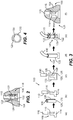
Fig. 3 is a schematic view of the system ofFig. 1 , showing a sequence in a process of making the system for protecting the brazed pairs of terminal leads; and -
Fig. 4 is a schematic plan view of a portion of the system ofFig. 1 , showing the overlapping edges of the insulation sleeve. - Reference will now be made to the drawings wherein like reference numerals identify similar structural features or aspects of the subject disclosure. For purposes of explanation and illustration, and not limitation, a partial view of an embodiment of a system in accordance with the disclosure is shown in
Fig. 1 and is designated generally byreference character 100. Other embodiments of systems in accordance with the disclosure, or aspects thereof, are provided inFigs. 2-3 , as will be described. The systems and methods described herein can be used to isolate terminal leads in an electric machine from one another, improving robustness against FOD (foreign object debris) induced short circuits and the like. -
System 100 includes aterminal block 102 mounted to anelectric machine housing 104 of anelectric machine 106, e.g., a generator for aerospace applications. Four pairs ofterminal leads 108 are mounted to theterminal block 102. Those skilled in the art will readily appreciate that any suitable number of pairs ofterminal leads 108 can be used without departing from the scope of this disclosure. Arespective wire 110 electrically connects each pair of terminal leads 108 astator 112 of theelectric machine 106. Each pair ofterminal leads 108 are joined together, e.g. the respective leads 114 and 116 in each pair ofterminal leads 108 can be brazed together, as indicated inFig. 3 and described more below. - With reference now to
Fig. 2 , there is apocket 118 defined in thehousing 104, where eachpair 108 of the terminal leads 114, 116 are seated. Aninsulative sleeve 120 is wrapped around the pair of terminal leads 108. Two lacings 122 (but any suitable number can be used) bind around theinsulative sleeve 120. Theinsulative sleeve 120 andlacings 122 can include fiberglass. Curedepoxy 124 can encase theinsulative sleeve 120 and lacing 122 in thepocket 118. - With reference now to
Fig. 3 , a method is shown for making thesystem 100. At block a, the two terminal leads 114, 116 are brazed together as a pair. Then at block b, a fiberglass sleeve or tube is cut, e.g., along the dotted line, into a sheet 126 with opposed first andsecond edges insulative sleeve 120 as shown at block c. Then at block d, the pair ofterminal leads 108 is wrapped in theinsulative sleeve 120. Wrapping the pair of terminal leads 108 in theinsulative sleeve 120 can include wrapping theinsulative sleeve 120 more than 360° around the pair of terminal leads 108 so that thefirst edge 130 of theinsulative sleeve 120 is tucked under thesecond edge 128 of theinsulative sleeve 120, as shown in the top view ofFig. 4 . At block e, the insulative sleeve is laced withlacings 122 to bind theinsulative sleeve 120 in place around the pair of terminal leads 108. - The procedure to this point can be performed on all four (or any other suitable number) of the pairs of terminal leads 108 shown in
Fig. 1 , while the pairs of terminal leads 108 andcorresponding wires 110 are mounted to theterminal block 102, but before theterminal block 102 is mounted to thehousing 104. At block e, the method includes binding theinsulative sleeve 120 to the pair of terminal leads with thelacings 122. After block e, thewires 110 can be threaded into thehousing 104 shown inFig. 1 , and theterminal block 102 can be mounted to thehousing 104. The method can include electrically connecting the terminal leads, using thewires 110, to astator 112 in theelectric machine housing 104. Block finFig. 3 shows that with theterminal block 102 mounted to thehousing 104 as shown inFig. 1 , the pair of terminal leads 108 and theinsulative sleeve 120 are seated in thepocket 118. As indicated in block f ofFig. 3 , the method can include spreadingepoxy 124 over theinsulative sleeve 120 and curing theepoxy 124 to encase theinsulative sleeve 120 around the pair of terminal leads 108 in thepocket 118. - The methods and systems of the present disclosure, as described above and shown in the drawings, provide for phase to phase terminal lead isolation and protection with superior performance relative to traditional techniques. While the apparatus and methods of the subject disclosure have been shown and described with reference to preferred embodiments, those skilled in the art will readily appreciate that changes and/or modifications may be made thereto without departing from the scope of the subject disclosure.
Claims (14)
the terminal block, wherein each additional pair of terminal leads has a respective insulative sleeve wrapped therearound.
and curing the epoxy.
The method as recited in claim 10 or 11, further comprising cutting a fiberglass sleeve into a sheet with opposed first and second edges for use as the insulative sleeve before wrapping the pair of terminal leads in the insulative sleeve.
leads so that the first edge of the insulative sleeve is tucked under the second edge of the insulative sleeve.
Applications Claiming Priority (1)
| Application Number | Priority Date | Filing Date | Title |
|---|---|---|---|
| US16/738,347 US11502574B2 (en) | 2020-01-09 | 2020-01-09 | Phase to phase terminal lead protection |
Publications (1)
| Publication Number | Publication Date |
|---|---|
| EP3849058A1 true EP3849058A1 (en) | 2021-07-14 |
Family
ID=74105953
Family Applications (1)
| Application Number | Title | Priority Date | Filing Date |
|---|---|---|---|
| EP21150610.0A Pending EP3849058A1 (en) | 2020-01-09 | 2021-01-07 | Phase to phase terminal lead protection |
Country Status (2)
| Country | Link |
|---|---|
| US (1) | US11502574B2 (en) |
| EP (1) | EP3849058A1 (en) |
Citations (6)
| Publication number | Priority date | Publication date | Assignee | Title |
|---|---|---|---|---|
| US3038093A (en) * | 1960-02-03 | 1962-06-05 | Gen Motors Corp | Dynamoelectric machine insulation system |
| JPS5286190A (en) * | 1976-01-14 | 1977-07-18 | Aichi Emerson Electric | Method of manufacturing insulator of electrical connecting portion and insulator of electrical connecting portion |
| JPS5357405A (en) * | 1976-11-04 | 1978-05-24 | Matsushita Electric Ind Co Ltd | Lead out wire connection part of motor stator insulation adhering method |
| US4160926A (en) * | 1975-06-20 | 1979-07-10 | The Epoxylite Corporation | Materials and impregnating compositions for insulating electric machines |
| JP2004119171A (en) * | 2002-09-26 | 2004-04-15 | Meidensha Corp | Insulating method, fixing method, insulating structure and fixing structure for electric wire connection part |
| US20150035396A1 (en) * | 2013-07-31 | 2015-02-05 | Fanuc Corporation | Motor provided with terminal block |
Family Cites Families (5)
| Publication number | Priority date | Publication date | Assignee | Title |
|---|---|---|---|---|
| US1975244A (en) * | 1932-07-08 | 1934-10-02 | United Dry Docks Inc | Joint for electrical conductors |
| JPS5393302A (en) * | 1977-01-26 | 1978-08-16 | Matsushita Electric Ind Co Ltd | Manufacturing method of lead out parts for motor stator |
| JPS53101601A (en) * | 1977-02-16 | 1978-09-05 | Matsushita Electric Ind Co Ltd | Insulation securing lead-out from motor stator |
| US4468083A (en) * | 1981-12-17 | 1984-08-28 | Monster Cable Products, Inc. | Crimped banana-type electrical connector and method thereof |
| US6315527B1 (en) * | 1999-04-12 | 2001-11-13 | Matsushita Electric Industrial Co., Ltd. | Motor-driven compressor |
-
2020
- 2020-01-09 US US16/738,347 patent/US11502574B2/en active Active
-
2021
- 2021-01-07 EP EP21150610.0A patent/EP3849058A1/en active Pending
Patent Citations (6)
| Publication number | Priority date | Publication date | Assignee | Title |
|---|---|---|---|---|
| US3038093A (en) * | 1960-02-03 | 1962-06-05 | Gen Motors Corp | Dynamoelectric machine insulation system |
| US4160926A (en) * | 1975-06-20 | 1979-07-10 | The Epoxylite Corporation | Materials and impregnating compositions for insulating electric machines |
| JPS5286190A (en) * | 1976-01-14 | 1977-07-18 | Aichi Emerson Electric | Method of manufacturing insulator of electrical connecting portion and insulator of electrical connecting portion |
| JPS5357405A (en) * | 1976-11-04 | 1978-05-24 | Matsushita Electric Ind Co Ltd | Lead out wire connection part of motor stator insulation adhering method |
| JP2004119171A (en) * | 2002-09-26 | 2004-04-15 | Meidensha Corp | Insulating method, fixing method, insulating structure and fixing structure for electric wire connection part |
| US20150035396A1 (en) * | 2013-07-31 | 2015-02-05 | Fanuc Corporation | Motor provided with terminal block |
Also Published As
| Publication number | Publication date |
|---|---|
| US20210218311A1 (en) | 2021-07-15 |
| US11502574B2 (en) | 2022-11-15 |
Similar Documents
| Publication | Publication Date | Title |
|---|---|---|
| US5508571A (en) | Neutral connection for wire wound stator | |
| CA1106891A (en) | Stator connection assembly and method of making the same | |
| US10971977B2 (en) | Stator for rotary electric machine and rotary electric machine | |
| US8749107B2 (en) | Spacer for supporting conductors in an electric machine | |
| US4822956A (en) | Coaxial cable | |
| US20130300232A1 (en) | Method of binding stator coils of motor | |
| US6700282B2 (en) | Rotary electric machine and method for connecting stator conductors | |
| US20160056678A1 (en) | Method for connecting motor wire | |
| US20140159519A1 (en) | Busbar that can be integrated into an electric motor | |
| US11502574B2 (en) | Phase to phase terminal lead protection | |
| US4698533A (en) | Connection insulator and stator assembly | |
| US4602424A (en) | Methods of insulating lead connections for dynamoelectric machine windings | |
| CN108808930A (en) | A kind of motor and its method for winding | |
| US2435284A (en) | Splice for conductors and method of splicing conductors | |
| EP2498379A1 (en) | Method for reciprocally connecting conductor ends to define coils of an electric machine | |
| US2412851A (en) | Dynamoelectric machine and method of making the same | |
| EP3113338A1 (en) | Dynamoelectric machine main lead servicing | |
| CN104242174A (en) | Manufacturing method of intermediate cable joint | |
| RU2382428C2 (en) | Method for superposition of electric insulating shell over varistor unit, and also varistor unit for overvoltage protection discharger | |
| RU2663207C1 (en) | Device for connecting electrical elements of electric rotary machine | |
| JP2000333397A (en) | stator | |
| CN109346321A (en) | A kind of production method of transformer coil insulated cushion block | |
| JP3420666B2 (en) | Method for manufacturing windings of rotating machine | |
| US2397187A (en) | Band for armatures | |
| US9502938B2 (en) | Wrapped stator coil for use in a generator |
Legal Events
| Date | Code | Title | Description |
|---|---|---|---|
| PUAI | Public reference made under article 153(3) epc to a published international application that has entered the european phase |
Free format text: ORIGINAL CODE: 0009012 |
|
| STAA | Information on the status of an ep patent application or granted ep patent |
Free format text: STATUS: THE APPLICATION HAS BEEN PUBLISHED |
|
| AK | Designated contracting states |
Kind code of ref document: A1 Designated state(s): AL AT BE BG CH CY CZ DE DK EE ES FI FR GB GR HR HU IE IS IT LI LT LU LV MC MK MT NL NO PL PT RO RS SE SI SK SM TR |
|
| STAA | Information on the status of an ep patent application or granted ep patent |
Free format text: STATUS: REQUEST FOR EXAMINATION WAS MADE |
|
| 17P | Request for examination filed |
Effective date: 20220112 |
|
| RBV | Designated contracting states (corrected) |
Designated state(s): AL AT BE BG CH CY CZ DE DK EE ES FI FR GB GR HR HU IE IS IT LI LT LU LV MC MK MT NL NO PL PT RO RS SE SI SK SM TR |
|
| STAA | Information on the status of an ep patent application or granted ep patent |
Free format text: STATUS: EXAMINATION IS IN PROGRESS |
|
| 17Q | First examination report despatched |
Effective date: 20240626 |
|
| GRAP | Despatch of communication of intention to grant a patent |
Free format text: ORIGINAL CODE: EPIDOSNIGR1 |
|
| STAA | Information on the status of an ep patent application or granted ep patent |
Free format text: STATUS: GRANT OF PATENT IS INTENDED |
|
| RIC1 | Information provided on ipc code assigned before grant |
Ipc: H02K 3/38 20060101AFI20251013BHEP Ipc: H02K 3/50 20060101ALI20251013BHEP Ipc: H02K 15/00 20060101ALI20251013BHEP Ipc: H02K 5/22 20060101ALN20251013BHEP |
|
| INTG | Intention to grant announced |
Effective date: 20251030 |
|
| GRAJ | Information related to disapproval of communication of intention to grant by the applicant or resumption of examination proceedings by the epo deleted |
Free format text: ORIGINAL CODE: EPIDOSDIGR1 |
|
| STAA | Information on the status of an ep patent application or granted ep patent |
Free format text: STATUS: EXAMINATION IS IN PROGRESS |
|
| GRAP | Despatch of communication of intention to grant a patent |
Free format text: ORIGINAL CODE: EPIDOSNIGR1 |
|
| STAA | Information on the status of an ep patent application or granted ep patent |
Free format text: STATUS: GRANT OF PATENT IS INTENDED |
|
| INTC | Intention to grant announced (deleted) | ||
| RIC1 | Information provided on ipc code assigned before grant |
Ipc: H02K 3/38 20060101AFI20260324BHEP Ipc: H02K 3/50 20060101ALI20260324BHEP Ipc: H02K 15/00 20060101ALI20260324BHEP Ipc: H02K 5/22 20060101ALN20260324BHEP |
|
| INTG | Intention to grant announced |
Effective date: 20260401 |