EP3849029A1 - Electrical mating systems - Google Patents
Electrical mating systems Download PDFInfo
- Publication number
- EP3849029A1 EP3849029A1 EP21150492.3A EP21150492A EP3849029A1 EP 3849029 A1 EP3849029 A1 EP 3849029A1 EP 21150492 A EP21150492 A EP 21150492A EP 3849029 A1 EP3849029 A1 EP 3849029A1
- Authority
- EP
- European Patent Office
- Prior art keywords
- seating
- opposing
- contactor
- mating surface
- contactors
- Prior art date
- Legal status (The legal status is an assumption and is not a legal conclusion. Google has not performed a legal analysis and makes no representation as to the accuracy of the status listed.)
- Granted
Links
Images

Classifications
-
- H—ELECTRICITY
- H01—ELECTRIC ELEMENTS
- H01R—ELECTRICALLY-CONDUCTIVE CONNECTIONS; STRUCTURAL ASSOCIATIONS OF A PLURALITY OF MUTUALLY-INSULATED ELECTRICAL CONNECTING ELEMENTS; COUPLING DEVICES; CURRENT COLLECTORS
- H01R13/00—Details of coupling devices of the kinds covered by groups H01R12/70 or H01R24/00 - H01R33/00
- H01R13/64—Means for preventing incorrect coupling
- H01R13/641—Means for preventing incorrect coupling by indicating incorrect coupling; by indicating correct or full engagement
-
- H—ELECTRICITY
- H01—ELECTRIC ELEMENTS
- H01R—ELECTRICALLY-CONDUCTIVE CONNECTIONS; STRUCTURAL ASSOCIATIONS OF A PLURALITY OF MUTUALLY-INSULATED ELECTRICAL CONNECTING ELEMENTS; COUPLING DEVICES; CURRENT COLLECTORS
- H01R13/00—Details of coupling devices of the kinds covered by groups H01R12/70 or H01R24/00 - H01R33/00
- H01R13/02—Contact members
- H01R13/04—Pins or blades for co-operation with sockets
-
- H—ELECTRICITY
- H01—ELECTRIC ELEMENTS
- H01R—ELECTRICALLY-CONDUCTIVE CONNECTIONS; STRUCTURAL ASSOCIATIONS OF A PLURALITY OF MUTUALLY-INSULATED ELECTRICAL CONNECTING ELEMENTS; COUPLING DEVICES; CURRENT COLLECTORS
- H01R13/00—Details of coupling devices of the kinds covered by groups H01R12/70 or H01R24/00 - H01R33/00
- H01R13/40—Securing contact members in or to a base or case; Insulating of contact members
- H01R13/42—Securing in a demountable manner
-
- H—ELECTRICITY
- H01—ELECTRIC ELEMENTS
- H01R—ELECTRICALLY-CONDUCTIVE CONNECTIONS; STRUCTURAL ASSOCIATIONS OF A PLURALITY OF MUTUALLY-INSULATED ELECTRICAL CONNECTING ELEMENTS; COUPLING DEVICES; CURRENT COLLECTORS
- H01R13/00—Details of coupling devices of the kinds covered by groups H01R12/70 or H01R24/00 - H01R33/00
- H01R13/66—Structural association with built-in electrical component
- H01R13/717—Structural association with built-in electrical component with built-in light source
-
- H—ELECTRICITY
- H01—ELECTRIC ELEMENTS
- H01R—ELECTRICALLY-CONDUCTIVE CONNECTIONS; STRUCTURAL ASSOCIATIONS OF A PLURALITY OF MUTUALLY-INSULATED ELECTRICAL CONNECTING ELEMENTS; COUPLING DEVICES; CURRENT COLLECTORS
- H01R13/00—Details of coupling devices of the kinds covered by groups H01R12/70 or H01R24/00 - H01R33/00
- H01R13/66—Structural association with built-in electrical component
- H01R13/717—Structural association with built-in electrical component with built-in light source
- H01R13/7175—Light emitting diodes (LEDs)
-
- H—ELECTRICITY
- H01—ELECTRIC ELEMENTS
- H01R—ELECTRICALLY-CONDUCTIVE CONNECTIONS; STRUCTURAL ASSOCIATIONS OF A PLURALITY OF MUTUALLY-INSULATED ELECTRICAL CONNECTING ELEMENTS; COUPLING DEVICES; CURRENT COLLECTORS
- H01R24/00—Two-part coupling devices, or either of their cooperating parts, characterised by their overall structure
- H01R24/28—Coupling parts carrying pins, blades or analogous contacts and secured only to wire or cable
-
- H—ELECTRICITY
- H05—ELECTRIC TECHNIQUES NOT OTHERWISE PROVIDED FOR
- H05K—PRINTED CIRCUITS; CASINGS OR CONSTRUCTIONAL DETAILS OF ELECTRIC APPARATUS; MANUFACTURE OF ASSEMBLAGES OF ELECTRICAL COMPONENTS
- H05K7/00—Constructional details common to different types of electric apparatus
- H05K7/02—Arrangements of circuit components or wiring on supporting structure
-
- H—ELECTRICITY
- H01—ELECTRIC ELEMENTS
- H01R—ELECTRICALLY-CONDUCTIVE CONNECTIONS; STRUCTURAL ASSOCIATIONS OF A PLURALITY OF MUTUALLY-INSULATED ELECTRICAL CONNECTING ELEMENTS; COUPLING DEVICES; CURRENT COLLECTORS
- H01R2107/00—Four or more poles
-
- H—ELECTRICITY
- H01—ELECTRIC ELEMENTS
- H01R—ELECTRICALLY-CONDUCTIVE CONNECTIONS; STRUCTURAL ASSOCIATIONS OF A PLURALITY OF MUTUALLY-INSULATED ELECTRICAL CONNECTING ELEMENTS; COUPLING DEVICES; CURRENT COLLECTORS
- H01R43/00—Apparatus or processes specially adapted for manufacturing, assembling, maintaining, or repairing of line connectors or current collectors or for joining electric conductors
- H01R43/20—Apparatus or processes specially adapted for manufacturing, assembling, maintaining, or repairing of line connectors or current collectors or for joining electric conductors for assembling or disassembling contact members with insulating base, case or sleeve
Definitions
- This disclosure relates to electrical mating systems for circuit components, e.g., for line replaceable units (LRUs).
- LRUs line replaceable units
- Line replaceable unit (LRU) connector can suffer from the same issue.
- An electrical mating system can include an electrical mating surface having a plurality of contactors, each contactor at least as long as a first length, the plurality of contactors configured to mate with a plurality of opposing contactors of an opposing mating surface.
- the electrical mating surface can include at least one seating contactor having a second length shorter than the first length.
- the system can include a contact module configured to determine if the at least one seating contactor is contacting an opposing seating contactor of an opposing mating surface.
- the contact module can be configured to activate an indicator to indicate whether the electrical mating surface and the opposing mating surface are properly seated together.
- the second length can be less than half of the first length. Any other suitable length less than the first length is contemplated herein.
- the plurality of contactors can be pins, the opposing contactors can be sockets, the opposing seating contactor can be an opposing seating socket, and the at least one seating contactor can be a seating contactor pin configured to insert into the seating opposing socket.
- the plurality of contactors can be sockets, the opposing contactors can be pins, the opposing seating contactor can be an opposing seating pin, and the at least one seating contactor can be a seating contactor socket configured to receive the seating opposing pin.
- the contact module can be mounted to electrical mating surface and electrically connected to at least the seating contactor pin. Any other suitable location and configuration for the contact module is contemplated herein.
- the contact module can include an LED, for example.
- the contact module can be configured to illuminate the LED for at least a period of time when the seating contactor is in contact with the opposing seating contactor. In certain embodiments, the contact module can be configured to illuminate the LED until the seating contactor is in contact with the opposing seating contactor.
- the system can include the opposing mating surface (e.g., a female connector if the electrical mating surface is male, and vice versa).
- the opposing mating surface e.g., a female connector if the electrical mating surface is male, and vice versa.
- a line replaceable unit can include an electrical mating surface as disclosed herein, e.g., as described above.
- the LRU can include any other suitable components, for example.
- a method can include inserting a plurality of pins of an LRU into a plurality of sockets of a receiving board and detecting if a seating pin of an LRU is fully seated in a seating socket of the receiving board.
- the seating pin can be shorter than the plurality of pins.
- the seating socket can be shorter than the plurality of sockets.
- FIG. 1 an illustrative view of an embodiment of a system in accordance with the disclosure is shown in Fig. 1 and is designated generally by reference character 100.
- FIGs. 2 and 3 Other embodiments and/or aspects of this disclosure are shown in Figs. 2 and 3 .
- Certain embodiments described herein can be used to ensure that a circuit module (e.g., an LRU) is properly mated to another circuit (e.g., a motherboard), or for any other suitable use.
- a circuit module e.g., an LRU
- another circuit e.g., a motherboard
- an electrical mating system 100 can include an electrical mating surface 101 having a plurality of contactors 103, each contactor 103 at least as long as a first length.
- the plurality of contactors 103 can be configured to mate with a plurality of opposing contactors 105 of an opposing mating surface 107.
- the electrical mating surface 101 can include at least one seating contactor 109 having a second length shorter than the first length.
- the second length can be less than half of the first length (e.g., as shown). Any other suitable length less than the first length is contemplated herein.
- the same or similar pin lengths can be used. For example, the inclusion of a mating pin in general can be used to ensure that the connector is engaged correctly. In some cases, connectors have been seated with pins not engaged at all. The use of a full length male and female pin could provide a simple basic seating check for the connector. Any other suitable lengths are contemplated herein.
- the system 100 can include a contact module 111 configured to determine if the at least one seating contactor 109 is contacting an opposing seating contactor 113 of an opposing mating surface 107.
- the contact module 111 can be configured to activate an indicator (e.g., send an indicator signal to a display) to indicate whether the electrical mating surface 101 and the opposing mating surface 107 are properly seated together (e.g., such that the contactors 103 are fully seated in the opposing contactors 105).
- the contact module 111 can be or include any suitable hardware module and/or software module configured to perform any suitable function disclosed herein.
- the control module 111 can be configured to communicate wirelessly or wired with a display system (e.g., including at least one LED) or any other suitable indicator system (e.g., visual, audible, tactile, data signals, etc.).
- an indicator system can include providing the status to an onboard circuit to utilize, such as a processor and/or logic device.
- a device can disable operation if all boards are not sensed as seated, or could provide indication, e.g., visual, audible, tactile, and/or signals (analog and/or digital) via a communications interface (e.g., Ethernet).
- a communications interface e.g., Ethernet
- Certain embodiment can also entirely use external test equipment to check the seating.
- an external LRU connector can be used that has, e.g., two pins that, when all boards are seated correctly, will be connected.
- Such test equipment can confirm this connection, for example. If any board (e.g., one or more boards of a system having one or a plurality of boards total) is not fully seated, the two pins would not be connected in such an embodiment. Any other suitable logic for detecting seating is contemplated herein.
- the plurality of contactors 103 can be pins
- the opposing contactors 105 can be sockets
- the opposing seating contactor 113 can be an opposing seating socket
- the at least one seating contactor 109 can be a seating contactor pin configured to insert into the seating opposing socket.
- the plurality of contactors 303 can be sockets
- the opposing contactors 305 can be pins
- the opposing seating contactor 313 can be an opposing seating pin
- the at least one seating contactor 309 can be a seating contactor socket configured to receive the seating opposing pin.
- the contact module 111 can be mounted to electrical mating surface 101 and electrically connected to at least the seating contactor pin. Any other suitable location and configuration for the contact module 111 is contemplated herein.
- the contact module 111 can include an LED 115, for example.
- the contact module 111 can be configured to illuminate the LED 115 for at least a period of time when the seating contactor 109, 309 is in contact with the opposing seating contactor 113, 313.
- the contact module 111 can be configured to illuminate the LED 115 until the seating contactor 109, 309 is in contact with the opposing seating contactor 113, 313.
- the system 100 can include the opposing mating surface 107, 307 (e.g., a female connector if the electrical mating surface 101, 301 is male, and vice versa).
- a complete circuit can be made (e.g., through another contactor pair) once the seating contactor and the opposing seating contactor mate and close the circuit.
- a plurality of mating surfaces can be utilized to create a daisy chain circuit to determine if the plurality of mating surfaces are properly seated such that the contact module 111 is configured to determine if all mating surfaces are properly seated.
- the opposing mating surface 107, 307 can be operatively connected to the contact module 111 instead of and/or in addition to the mating surfaces 101, 301.
- a line replaceable unit e.g., 102, 202, 302 can include an electrical mating surface 101, 301 as disclosed herein, e.g., as described above.
- the LRU 102, 202, 302 can include any other suitable components, for example.
- the opposing mating surface 107, 307 can be part of a motherboard 104, 204, 304 that the LRU 102, 202, 302 can mate with.
- the LRU 102, 202, 302 can be configured to perform any suitable function or for any suitable use (e.g., aircraft use).
- a method can include inserting a plurality of pins of an LRU into a plurality of sockets of a receiving board and detecting if a seating pin of an LRU is fully seated in a seating socket of the receiving board.
- the seating pin can be shorter than the plurality of pins.
- the seating socket can be shorter than the plurality of sockets.
- Certain embodiments can include at least one extra shorter pin connection and a logic circuit for detecting when the shorter pin is seated.
- the shorter extra pin may only connect electrically to the socket on other side if all pins are fully seated, for example.
- Embodiments can have an LED light indicating the pin is touching other side, or any other suitable logic circuit (e.g., to send a warning to a user for example that the mating surfaces are not properly seated).
- an LED and/or logic circuit can be on circuit boards being inserted, or can be on motherboard receiving the circuit boards.
- Embodiments can be used for any mating type surface where there is a pressure connection between electrical interfaces (e.g., USB), for example, or any other suitable mating surface.
- Embodiments include a method to confirm proper board or LRU seating.
- Embodiments can utilize one or more spare connector pins to create a feedback loop to identify when boards that are not seated. Using a shorter than normal pin for this function can allow determining if the board is only partially seated, and an LED or other suitable indicator can be used to annunciate the status. Embodiments can be used with LRUs. Embodiments can provide improved field reliability, fewer zero hour returns, and data can also be used for health management to predict a future issues.
- aspects of the present disclosure may be embodied as a system, method or computer program product. Accordingly, aspects of this disclosure may take the form of an entirely hardware embodiment, an entirely software embodiment (including firmware, resident software, micro-code, etc.), or an embodiment combining software and hardware aspects, all possibilities of which can be referred to herein as a "circuit,” “module,” or “system.”
- a “circuit,” “module,” or “system” can include one or more portions of one or more separate physical hardware and/or software components that can together perform the disclosed function of the "circuit,” “module,” or “system”, or a “circuit,” “module,” or “system” can be a single self-contained unit (e.g., of hardware and/or software).
- aspects of this disclosure may take the form of a computer program product embodied in one or more computer readable medium(s) having computer readable program code embodied thereon.
- the computer readable medium may be a computer readable signal medium or a computer readable storage medium.
- a computer readable storage medium may be, for example, but not limited to, an electronic, magnetic, optical, electromagnetic, infrared, or semiconductor system, apparatus, or device, or any suitable combination of the foregoing.
- a computer readable storage medium may be any tangible medium that can contain, or store a program for use by or in connection with an instruction execution system, apparatus, or device.
- a computer readable signal medium may include a propagated data signal with computer readable program code embodied therein, for example, in baseband or as part of a carrier wave. Such a propagated signal may take any of a variety of forms, including, but not limited to, electro-magnetic, optical, or any suitable combination thereof.
- a computer readable signal medium may be any computer readable medium that is not a computer readable storage medium and that can communicate, propagate, or transport a program for use by or in connection with an instruction execution system, apparatus, or device.
- Program code embodied on a computer readable medium may be transmitted using any appropriate medium, including but not limited to wireless, wireline, optical fiber cable, RF, etc., or any suitable combination of the foregoing.
- Computer program code for carrying out operations for aspects of this disclosure may be written in any combination of one or more programming languages, including an object oriented programming language such as Java, Smalltalk, C++ or the like and conventional procedural programming languages, such as the "C" programming language or similar programming languages.
- the program code may execute entirely on the user's computer, partly on the user's computer, as a stand-alone software package, partly on the user's computer and partly on a remote computer or entirely on the remote computer or server.
- the remote computer may be connected to the user's computer through any type of network, including a local area network (LAN) or a wide area network (WAN), or the connection may be made to an external computer (for example, through the Internet using an Internet Service Provider).
- LAN local area network
- WAN wide area network
- Internet Service Provider for example, AT&T, MCI, Sprint, EarthLink, MSN, GTE, etc.
- These computer program instructions may also be stored in a computer readable medium that can direct a computer, other programmable data processing apparatus, or other devices to function in a particular manner, such that the instructions stored in the computer readable medium produce an article of manufacture including instructions which implement the function/act specified in the flowchart and/or block diagram block or blocks.
- the computer program instructions may also be loaded onto a computer, other programmable data processing apparatus, or other devices to cause a series of operational steps to be performed on the computer, other programmable apparatus or other devices to produce a computer implemented process such that the instructions which execute on the computer or other programmable apparatus provide processes for implementing the functions/acts specified herein.
- any numerical values disclosed herein can be exact values or can be values within a range. Further, any terms of approximation (e.g., “about”, “approximately”, “around”) used in this disclosure can mean the stated value within a range. For example, in certain embodiments, the range can be within (plus or minus) 20%, or within 10%, or within 5%, or within 2%, or within any other suitable percentage or number as appreciated by those having ordinary skill in the art (e.g., for known tolerance limits or error ranges).
- a reference to "A and/or B", when used in conjunction with open-ended language such as “comprising” can refer, in one embodiment, to A only (optionally including elements other than B); in another embodiment, to B only (optionally including elements other than A); in yet another embodiment, to both A and B (optionally including other elements); etc.
Landscapes
- Engineering & Computer Science (AREA)
- Microelectronics & Electronic Packaging (AREA)
- Physics & Mathematics (AREA)
- Optics & Photonics (AREA)
- Details Of Connecting Devices For Male And Female Coupling (AREA)
Abstract
Description
- This disclosure relates to electrical mating systems for circuit components, e.g., for line replaceable units (LRUs).
- Circuit boards are often not fully seated during assembly resulting in possible disengagement of the connector as the unit is effected by vibration and temperature cycles. Line replaceable unit (LRU) connector can suffer from the same issue.
- Such conventional methods and systems have generally been considered satisfactory for their intended purpose. However, there is still a need in the art for improved electrical mating systems. The present disclosure provides a solution for this need.
- An electrical mating system can include an electrical mating surface having a plurality of contactors, each contactor at least as long as a first length, the plurality of contactors configured to mate with a plurality of opposing contactors of an opposing mating surface. The electrical mating surface can include at least one seating contactor having a second length shorter than the first length. The system can include a contact module configured to determine if the at least one seating contactor is contacting an opposing seating contactor of an opposing mating surface. The contact module can be configured to activate an indicator to indicate whether the electrical mating surface and the opposing mating surface are properly seated together.
- In certain embodiments, the second length can be less than half of the first length. Any other suitable length less than the first length is contemplated herein.
- In certain embodiments, the plurality of contactors can be pins, the opposing contactors can be sockets, the opposing seating contactor can be an opposing seating socket, and the at least one seating contactor can be a seating contactor pin configured to insert into the seating opposing socket. In certain embodiments, the plurality of contactors can be sockets, the opposing contactors can be pins, the opposing seating contactor can be an opposing seating pin, and the at least one seating contactor can be a seating contactor socket configured to receive the seating opposing pin.
- In certain embodiments, the contact module can be mounted to electrical mating surface and electrically connected to at least the seating contactor pin. Any other suitable location and configuration for the contact module is contemplated herein.
- The contact module can include an LED, for example. The contact module can be configured to illuminate the LED for at least a period of time when the seating contactor is in contact with the opposing seating contactor. In certain embodiments, the contact module can be configured to illuminate the LED until the seating contactor is in contact with the opposing seating contactor.
- In certain embodiments, the system can include the opposing mating surface (e.g., a female connector if the electrical mating surface is male, and vice versa).
- In accordance with at least one aspect of this disclosure, a line replaceable unit (LRU) can include an electrical mating surface as disclosed herein, e.g., as described above. The LRU can include any other suitable components, for example.
- A method can include inserting a plurality of pins of an LRU into a plurality of sockets of a receiving board and detecting if a seating pin of an LRU is fully seated in a seating socket of the receiving board. In certain embodiments, the seating pin can be shorter than the plurality of pins. In certain embodiments, the seating socket can be shorter than the plurality of sockets.
- These and other features of the embodiments of the subject disclosure will become more readily apparent to those skilled in the art from the following detailed description taken in conjunction with the drawings.
- So that those skilled in the art to which the subject disclosure appertains will readily understand how to make and use the devices and methods of the subject disclosure without undue experimentation, embodiments thereof will be described in detail herein below with reference to certain figures, wherein:
-
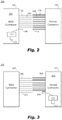
Fig. 1 is a schematic diagram of an embodiment of a system in accordance with this disclosure, showing a shorter seating contactor pin; -
Fig. 2 is a schematic diagram of an embodiment of a system in accordance with this disclosure, shown having a contact module integrated with an electrical mating surface; and -
Fig. 3 is a schematic diagram of an embodiment of a system in accordance with this disclosure, showing a shorter seating contactor socket. - Reference will now be made to the drawings wherein like reference numerals identify similar structural features or aspects of the subject disclosure. For purposes of explanation and illustration, and not limitation, an illustrative view of an embodiment of a system in accordance with the disclosure is shown in
Fig. 1 and is designated generally byreference character 100. Other embodiments and/or aspects of this disclosure are shown inFigs. 2 and 3 . Certain embodiments described herein can be used to ensure that a circuit module (e.g., an LRU) is properly mated to another circuit (e.g., a motherboard), or for any other suitable use. - Referring to
Fig. 1 , anelectrical mating system 100 can include anelectrical mating surface 101 having a plurality ofcontactors 103, eachcontactor 103 at least as long as a first length. The plurality ofcontactors 103 can be configured to mate with a plurality ofopposing contactors 105 of anopposing mating surface 107. Theelectrical mating surface 101 can include at least oneseating contactor 109 having a second length shorter than the first length. - In certain embodiments, the second length can be less than half of the first length (e.g., as shown). Any other suitable length less than the first length is contemplated herein. In certain embodiments, the same or similar pin lengths can be used. For example, the inclusion of a mating pin in general can be used to ensure that the connector is engaged correctly. In some cases, connectors have been seated with pins not engaged at all. The use of a full length male and female pin could provide a simple basic seating check for the connector. Any other suitable lengths are contemplated herein.
- The
system 100 can include acontact module 111 configured to determine if the at least oneseating contactor 109 is contacting anopposing seating contactor 113 of anopposing mating surface 107. Thecontact module 111 can be configured to activate an indicator (e.g., send an indicator signal to a display) to indicate whether theelectrical mating surface 101 and theopposing mating surface 107 are properly seated together (e.g., such that thecontactors 103 are fully seated in the opposing contactors 105). Thecontact module 111 can be or include any suitable hardware module and/or software module configured to perform any suitable function disclosed herein. Thecontrol module 111 can be configured to communicate wirelessly or wired with a display system (e.g., including at least one LED) or any other suitable indicator system (e.g., visual, audible, tactile, data signals, etc.). - Certain embodiments of an indicator system can include providing the status to an onboard circuit to utilize, such as a processor and/or logic device. In certain embodiments, such a device can disable operation if all boards are not sensed as seated, or could provide indication, e.g., visual, audible, tactile, and/or signals (analog and/or digital) via a communications interface (e.g., Ethernet).
- Certain embodiment can also entirely use external test equipment to check the seating. For example, an external LRU connector can be used that has, e.g., two pins that, when all boards are seated correctly, will be connected. Such test equipment can confirm this connection, for example. If any board (e.g., one or more boards of a system having one or a plurality of boards total) is not fully seated, the two pins would not be connected in such an embodiment. Any other suitable logic for detecting seating is contemplated herein.
- In certain embodiments, as shown in
Fig. 1 , the plurality ofcontactors 103 can be pins, theopposing contactors 105 can be sockets, theopposing seating contactor 113 can be an opposing seating socket, and the at least oneseating contactor 109 can be a seating contactor pin configured to insert into the seating opposing socket. In certain embodiments, e.g., as shown inFig. 3 , the plurality ofcontactors 303 can be sockets, theopposing contactors 305 can be pins, theopposing seating contactor 313 can be an opposing seating pin, and the at least oneseating contactor 309 can be a seating contactor socket configured to receive the seating opposing pin. - In certain embodiments, as shown in
Figs. 2 and 3 , insystems contact module 111 can be mounted toelectrical mating surface 101 and electrically connected to at least the seating contactor pin. Any other suitable location and configuration for thecontact module 111 is contemplated herein. - The
contact module 111 can include anLED 115, for example. Thecontact module 111 can be configured to illuminate theLED 115 for at least a period of time when theseating contactor seating contactor contact module 111 can be configured to illuminate theLED 115 until theseating contactor seating contactor - In certain embodiments, the
system 100 can include the opposingmating surface 107, 307 (e.g., a female connector if theelectrical mating surface contact module 111 is configured to determine if all mating surfaces are properly seated. In certain embodiments, it is contemplated that the opposingmating surface contact module 111 instead of and/or in addition to the mating surfaces 101, 301. - In accordance with at least one aspect of this disclosure, a line replaceable unit (LRU), e.g., 102, 202, 302 can include an
electrical mating surface LRU mating surface LRU LRU - A method can include inserting a plurality of pins of an LRU into a plurality of sockets of a receiving board and detecting if a seating pin of an LRU is fully seated in a seating socket of the receiving board. In certain embodiments, the seating pin can be shorter than the plurality of pins. In certain embodiments, the seating socket can be shorter than the plurality of sockets.
- Certain embodiments can include at least one extra shorter pin connection and a logic circuit for detecting when the shorter pin is seated. The shorter extra pin may only connect electrically to the socket on other side if all pins are fully seated, for example. Embodiments can have an LED light indicating the pin is touching other side, or any other suitable logic circuit (e.g., to send a warning to a user for example that the mating surfaces are not properly seated). In certain embodiments, an LED and/or logic circuit can be on circuit boards being inserted, or can be on motherboard receiving the circuit boards.
- Embodiments can be used for any mating type surface where there is a pressure connection between electrical interfaces (e.g., USB), for example, or any other suitable mating surface. Embodiments include a method to confirm proper board or LRU seating.
- Embodiments can utilize one or more spare connector pins to create a feedback loop to identify when boards that are not seated. Using a shorter than normal pin for this function can allow determining if the board is only partially seated, and an LED or other suitable indicator can be used to annunciate the status. Embodiments can be used with LRUs. Embodiments can provide improved field reliability, fewer zero hour returns, and data can also be used for health management to predict a future issues.
- As will be appreciated by those skilled in the art, aspects of the present disclosure may be embodied as a system, method or computer program product. Accordingly, aspects of this disclosure may take the form of an entirely hardware embodiment, an entirely software embodiment (including firmware, resident software, micro-code, etc.), or an embodiment combining software and hardware aspects, all possibilities of which can be referred to herein as a "circuit," "module," or "system." A "circuit," "module," or "system" can include one or more portions of one or more separate physical hardware and/or software components that can together perform the disclosed function of the "circuit," "module," or "system", or a "circuit," "module," or "system" can be a single self-contained unit (e.g., of hardware and/or software). Furthermore, aspects of this disclosure may take the form of a computer program product embodied in one or more computer readable medium(s) having computer readable program code embodied thereon.
- Any combination of one or more computer readable medium(s) may be utilized. The computer readable medium may be a computer readable signal medium or a computer readable storage medium. A computer readable storage medium may be, for example, but not limited to, an electronic, magnetic, optical, electromagnetic, infrared, or semiconductor system, apparatus, or device, or any suitable combination of the foregoing. More specific examples (a non-exhaustive list) of the computer readable storage medium would include the following: an electrical connection having one or more wires, a portable computer diskette, a hard disk, a random access memory (RAM), a read-only memory (ROM), an erasable programmable read-only memory (EPROM or Flash memory), an optical fiber, a portable compact disc read-only memory (CD-ROM), an optical storage device, a magnetic storage device, or any suitable combination of the foregoing. In the context of this document, a computer readable storage medium may be any tangible medium that can contain, or store a program for use by or in connection with an instruction execution system, apparatus, or device.
- A computer readable signal medium may include a propagated data signal with computer readable program code embodied therein, for example, in baseband or as part of a carrier wave. Such a propagated signal may take any of a variety of forms, including, but not limited to, electro-magnetic, optical, or any suitable combination thereof. A computer readable signal medium may be any computer readable medium that is not a computer readable storage medium and that can communicate, propagate, or transport a program for use by or in connection with an instruction execution system, apparatus, or device.
- Program code embodied on a computer readable medium may be transmitted using any appropriate medium, including but not limited to wireless, wireline, optical fiber cable, RF, etc., or any suitable combination of the foregoing.
- Computer program code for carrying out operations for aspects of this disclosure may be written in any combination of one or more programming languages, including an object oriented programming language such as Java, Smalltalk, C++ or the like and conventional procedural programming languages, such as the "C" programming language or similar programming languages. The program code may execute entirely on the user's computer, partly on the user's computer, as a stand-alone software package, partly on the user's computer and partly on a remote computer or entirely on the remote computer or server. In the latter scenario, the remote computer may be connected to the user's computer through any type of network, including a local area network (LAN) or a wide area network (WAN), or the connection may be made to an external computer (for example, through the Internet using an Internet Service Provider).
- Aspects of the this disclosure may be described above with reference to flowchart illustrations and/or block diagrams of methods, apparatus (systems) and computer program products according to embodiments of this disclosure. It will be understood that each block of any flowchart illustrations and/or block diagrams, and combinations of blocks in any flowchart illustrations and/or block diagrams, can be implemented by computer program instructions. These computer program instructions may be provided to a processor of a general purpose computer, special purpose computer, or other programmable data processing apparatus to produce a machine, such that the instructions, which execute via the processor of the computer or other programmable data processing apparatus, create means for implementing the functions/acts specified in any flowchart and/or block diagram block or blocks.
- These computer program instructions may also be stored in a computer readable medium that can direct a computer, other programmable data processing apparatus, or other devices to function in a particular manner, such that the instructions stored in the computer readable medium produce an article of manufacture including instructions which implement the function/act specified in the flowchart and/or block diagram block or blocks.
- The computer program instructions may also be loaded onto a computer, other programmable data processing apparatus, or other devices to cause a series of operational steps to be performed on the computer, other programmable apparatus or other devices to produce a computer implemented process such that the instructions which execute on the computer or other programmable apparatus provide processes for implementing the functions/acts specified herein.
- Those having ordinary skill in the art understand that any numerical values disclosed herein can be exact values or can be values within a range. Further, any terms of approximation (e.g., "about", "approximately", "around") used in this disclosure can mean the stated value within a range. For example, in certain embodiments, the range can be within (plus or minus) 20%, or within 10%, or within 5%, or within 2%, or within any other suitable percentage or number as appreciated by those having ordinary skill in the art (e.g., for known tolerance limits or error ranges).
- The articles "a", "an", and "the" as used herein and in the appended claims are used herein to refer to one or to more than one (i.e., to at least one) of the grammatical object of the article unless the context clearly indicates otherwise. By way of example, "an element" means one element or more than one element.
- The phrase "and/or," as used herein in the specification and in the claims, should be understood to mean "either or both" of the elements so conjoined, i.e., elements that are conjunctively present in some cases and disjunctively present in other cases. Multiple elements listed with "and/or" should be construed in the same fashion, i.e., "one or more" of the elements so conjoined. Other elements may optionally be present other than the elements specifically identified by the "and/or" clause, whether related or unrelated to those elements specifically identified. Thus, as a non-limiting example, a reference to "A and/or B", when used in conjunction with open-ended language such as "comprising" can refer, in one embodiment, to A only (optionally including elements other than B); in another embodiment, to B only (optionally including elements other than A); in yet another embodiment, to both A and B (optionally including other elements); etc.
- As used herein in the specification and in the claims, "or" should be understood to have the same meaning as "and/or" as defined above. For example, when separating items in a list, "or" or "and/or" shall be interpreted as being inclusive, i.e., the inclusion of at least one, but also including more than one, of a number or list of elements, and, optionally, additional unlisted items. Only terms clearly indicated to the contrary, such as "only one of' or "exactly one of," or, when used in the claims, "consisting of," will refer to the inclusion of exactly one element of a number or list of elements. In general, the term "or" as used herein shall only be interpreted as indicating exclusive alternatives (i.e., "one or the other but not both") when preceded by terms of exclusivity, such as "either," "one of," "only one of," or "exactly one of."
- Any suitable combination(s) of any disclosed embodiments and/or any suitable portion(s) thereof are contemplated herein as appreciated by those having ordinary skill in the art in view of this disclosure.
- The embodiments of the present disclosure, as described above and shown in the drawings, provide for improvement in the art to which they pertain. While the subject disclosure includes reference to certain embodiments, those skilled in the art will readily appreciate that changes and/or modifications may be made thereto without departing from the scope of the subject disclosure.
Claims (13)
- An electrical mating system, comprising:
an electrical mating surface (101) having:a plurality of contactors (103), each contactor at least as long as a first length, wherein the plurality of contactors are configured to mate with a plurality of opposing contactors (105) of an opposing mating surface (107); andat least one seating contactor (109) having a second length shorter than the first length; anda contact module (111) configured to determine if the at least one seating contactor (109) is contacting an opposing seating contactor (113) of an opposing mating surface (107), and to activate an indicator to indicate whether the electrical mating surface (101) and the opposing mating surface (107) are properly seated together. - The system of claim 1, wherein the plurality of contactors (103) are pins, the opposing contactors (105) are sockets, the opposing seating contactor (113) is an opposing seating socket, and the at least one seating contactor (109) is a seating contactor pin configured to insert into the seating opposing socket.
- The system of claim 2, wherein the contact module (111) is mounted to electrical mating surface and electrically connected to at least the seating contactor pin.
- The system of claim 1, wherein the plurality of contactors (103) are sockets, the opposing contactors (105) are pins, the opposing seating contactor (113) is an opposing seating pin, and the at least one seating contactor (109) is a seating contactor socket configured to receive the seating opposing pin.
- The system of any preceding claim, wherein the contact module (111) includes an LED.
- The system of claim 5, wherein the contact module (111) is configured to illuminate the LED for at least a period of time when the seating contactor is in contact with the opposing seating contactor.
- The system of claim 5, wherein the contact module (111) is configured to illuminate the LED until the seating contactor is in contact with the opposing seating contactor.
- The system of any preceding claim, further comprising the opposing mating surface.
- The system of any preceding claim, wherein the second length is less than half of the first length.
- A line replaceable unit (LRU), comprising:
an electrical mating system of any preceding claim. - A method, comprising:inserting a plurality of pins of an LRU into a plurality of sockets of a receiving board; anddetecting if a seating pin of an LRU is fully seated in a seating socket of the receiving board.
- The method of claim 11, wherein the seating pin is shorter than the plurality of pins.
- The method of claim 11, wherein the seating socket is shorter than the plurality of sockets.
Applications Claiming Priority (1)
| Application Number | Priority Date | Filing Date | Title |
|---|---|---|---|
| US16/736,287 US11637392B2 (en) | 2020-01-07 | 2020-01-07 | Electrical mating systems |
Publications (2)
| Publication Number | Publication Date |
|---|---|
| EP3849029A1 true EP3849029A1 (en) | 2021-07-14 |
| EP3849029B1 EP3849029B1 (en) | 2024-04-03 |
Family
ID=74105891
Family Applications (1)
| Application Number | Title | Priority Date | Filing Date |
|---|---|---|---|
| EP21150492.3A Active EP3849029B1 (en) | 2020-01-07 | 2021-01-07 | Electrical mating systems |
Country Status (2)
| Country | Link |
|---|---|
| US (2) | US11637392B2 (en) |
| EP (1) | EP3849029B1 (en) |
Families Citing this family (1)
| Publication number | Priority date | Publication date | Assignee | Title |
|---|---|---|---|---|
| US11637392B2 (en) * | 2020-01-07 | 2023-04-25 | Hamilton Sundstrand Corporation | Electrical mating systems |
Citations (3)
| Publication number | Priority date | Publication date | Assignee | Title |
|---|---|---|---|---|
| US4915648A (en) * | 1988-03-04 | 1990-04-10 | Fuji Jukogyo Kabushiki Kaisha | Connector with a lock mechanism |
| US7278791B2 (en) * | 2005-02-24 | 2007-10-09 | Radiall | Contact element for a multicontact connector, and such a connector |
| DE102011050638A1 (en) * | 2010-06-10 | 2012-03-22 | Fanuc Corporation | connector |
Family Cites Families (13)
| Publication number | Priority date | Publication date | Assignee | Title |
|---|---|---|---|---|
| US5235740A (en) | 1991-03-22 | 1993-08-17 | International Business Machines Corporation | Press with pin detection for interference connectors |
| GB9117745D0 (en) * | 1991-08-15 | 1991-10-02 | Bicc Plc | Circuit board connector |
| US8240077B2 (en) | 2002-03-04 | 2012-08-14 | Larry Holmberg | Range finder for weapons |
| US6919813B2 (en) | 2003-05-16 | 2005-07-19 | Hewlett-Packard Development Company, L.P. | Built-in circuitry and method to test connector loading |
| US6933853B2 (en) | 2003-06-12 | 2005-08-23 | Hewlett-Packard Development Company, L.P. | Apparatus and method for detecting and communicating interconnect failures |
| US20050024220A1 (en) | 2003-06-12 | 2005-02-03 | Shidla Dale John | Built-in circuitry and method to test connectivity to integrated circuit |
| US7237401B2 (en) | 2003-07-02 | 2007-07-03 | Adobeair, Inc. | Low profile evaporative cooler |
| US8226443B2 (en) * | 2007-04-20 | 2012-07-24 | Hewlett-Packard Development Company, L.P. | Interconnect detection system |
| DE102007022210B3 (en) * | 2007-05-11 | 2008-12-18 | Iprm Intellectual Property Rights Management Ag | Multi-level connector system for medical use |
| US20130017732A1 (en) | 2011-01-15 | 2013-01-17 | Parke Eugene James | Method and apparatus for detecting improper connector seating or engagement |
| US9118144B2 (en) * | 2012-06-08 | 2015-08-25 | International Business Machines Corporation | Multi-level connector and use thereof that mitigates data signaling reflections |
| US9105993B2 (en) * | 2012-10-18 | 2015-08-11 | Actronix, Inc. | Terminal testing adapter and device |
| US11637392B2 (en) * | 2020-01-07 | 2023-04-25 | Hamilton Sundstrand Corporation | Electrical mating systems |
-
2020
- 2020-01-07 US US16/736,287 patent/US11637392B2/en active Active
-
2021
- 2021-01-07 EP EP21150492.3A patent/EP3849029B1/en active Active
-
2023
- 2023-04-24 US US18/138,434 patent/US20230344160A1/en active Pending
Patent Citations (3)
| Publication number | Priority date | Publication date | Assignee | Title |
|---|---|---|---|---|
| US4915648A (en) * | 1988-03-04 | 1990-04-10 | Fuji Jukogyo Kabushiki Kaisha | Connector with a lock mechanism |
| US7278791B2 (en) * | 2005-02-24 | 2007-10-09 | Radiall | Contact element for a multicontact connector, and such a connector |
| DE102011050638A1 (en) * | 2010-06-10 | 2012-03-22 | Fanuc Corporation | connector |
Also Published As
| Publication number | Publication date |
|---|---|
| US11637392B2 (en) | 2023-04-25 |
| EP3849029B1 (en) | 2024-04-03 |
| US20210210884A1 (en) | 2021-07-08 |
| US20230344160A1 (en) | 2023-10-26 |
Similar Documents
| Publication | Publication Date | Title |
|---|---|---|
| US9853492B2 (en) | Automatic transfer switch module | |
| US10103489B2 (en) | Validating connection, structural characteristics and positioning of cable connectors | |
| CN103531961B (en) | Electronic module in being inserted into bearing element | |
| EP3024096A1 (en) | Electrical connector and electronic device including the same | |
| CN103534983B (en) | The detection method of cable grafting situation and device | |
| US20230344160A1 (en) | Electrical mating systems | |
| US20140321810A1 (en) | Connector detection | |
| CN105335542A (en) | In-place state monitoring device and method and communication equipment | |
| CN119852937A (en) | PCB over-temperature protection device, method and equipment | |
| WO2007039904A3 (en) | Method and system for securing input from an external device to a host | |
| EP3849291A1 (en) | Circuit retainer systems | |
| CN112506291A (en) | Backboard cascading device and electronic equipment | |
| JP6557980B2 (en) | Differential signal cable characteristic determination device and characteristic determination method | |
| EP2664935B1 (en) | Automatic test equipment control device | |
| CN115542848A (en) | Terminal block unit for input/output device of modular process control system | |
| JP5638045B2 (en) | Numerical control system with detachable filter circuit | |
| US12327957B2 (en) | Systems and methods for detecting misshapen receptacle connector | |
| JP2018041147A (en) | Electronic device, cooling fan controller, cooling fan control program, and cooling fan control method | |
| CN119939640A (en) | A method, device, equipment and readable storage medium for secure communication between BIOS and BMC | |
| US12133349B2 (en) | Intelligent cable topology detection | |
| KR20200088137A (en) | Apparatus and method for duplexing input of plc | |
| CN109697149A (en) | Server and external function element-interconn ection state detecting method, system and server | |
| US12314034B2 (en) | Method for managing management board of immersion cooling tank, management board of immersion cooling tank, immersion cooling tank, and non-transitory storage medium | |
| JP2014176259A (en) | Power connection device and connection confirmation method | |
| US10169965B1 (en) | Physical mesh barrier for protection of server rack |
Legal Events
| Date | Code | Title | Description |
|---|---|---|---|
| PUAI | Public reference made under article 153(3) epc to a published international application that has entered the european phase |
Free format text: ORIGINAL CODE: 0009012 |
|
| STAA | Information on the status of an ep patent application or granted ep patent |
Free format text: STATUS: THE APPLICATION HAS BEEN PUBLISHED |
|
| AK | Designated contracting states |
Kind code of ref document: A1 Designated state(s): AL AT BE BG CH CY CZ DE DK EE ES FI FR GB GR HR HU IE IS IT LI LT LU LV MC MK MT NL NO PL PT RO RS SE SI SK SM TR |
|
| STAA | Information on the status of an ep patent application or granted ep patent |
Free format text: STATUS: REQUEST FOR EXAMINATION WAS MADE |
|
| 17P | Request for examination filed |
Effective date: 20220113 |
|
| RBV | Designated contracting states (corrected) |
Designated state(s): AL AT BE BG CH CY CZ DE DK EE ES FI FR GB GR HR HU IE IS IT LI LT LU LV MC MK MT NL NO PL PT RO RS SE SI SK SM TR |
|
| GRAP | Despatch of communication of intention to grant a patent |
Free format text: ORIGINAL CODE: EPIDOSNIGR1 |
|
| STAA | Information on the status of an ep patent application or granted ep patent |
Free format text: STATUS: GRANT OF PATENT IS INTENDED |
|
| INTG | Intention to grant announced |
Effective date: 20231109 |
|
| GRAS | Grant fee paid |
Free format text: ORIGINAL CODE: EPIDOSNIGR3 |
|
| GRAA | (expected) grant |
Free format text: ORIGINAL CODE: 0009210 |
|
| STAA | Information on the status of an ep patent application or granted ep patent |
Free format text: STATUS: THE PATENT HAS BEEN GRANTED |
|
| AK | Designated contracting states |
Kind code of ref document: B1 Designated state(s): AL AT BE BG CH CY CZ DE DK EE ES FI FR GB GR HR HU IE IS IT LI LT LU LV MC MK MT NL NO PL PT RO RS SE SI SK SM TR |
|
| REG | Reference to a national code |
Ref country code: CH Ref legal event code: EP |
|
| REG | Reference to a national code |
Ref country code: IE Ref legal event code: FG4D |
|
| REG | Reference to a national code |
Ref country code: DE Ref legal event code: R096 Ref document number: 602021011072 Country of ref document: DE |
|
| REG | Reference to a national code |
Ref country code: LT Ref legal event code: MG9D |
|
| REG | Reference to a national code |
Ref country code: NL Ref legal event code: MP Effective date: 20240403 |
|
| REG | Reference to a national code |
Ref country code: AT Ref legal event code: MK05 Ref document number: 1673431 Country of ref document: AT Kind code of ref document: T Effective date: 20240403 |
|
| PG25 | Lapsed in a contracting state [announced via postgrant information from national office to epo] |
Ref country code: NL Free format text: LAPSE BECAUSE OF FAILURE TO SUBMIT A TRANSLATION OF THE DESCRIPTION OR TO PAY THE FEE WITHIN THE PRESCRIBED TIME-LIMIT Effective date: 20240403 |
|
| PG25 | Lapsed in a contracting state [announced via postgrant information from national office to epo] |
Ref country code: NL Free format text: LAPSE BECAUSE OF FAILURE TO SUBMIT A TRANSLATION OF THE DESCRIPTION OR TO PAY THE FEE WITHIN THE PRESCRIBED TIME-LIMIT Effective date: 20240403 |
|
| PG25 | Lapsed in a contracting state [announced via postgrant information from national office to epo] |
Ref country code: IS Free format text: LAPSE BECAUSE OF FAILURE TO SUBMIT A TRANSLATION OF THE DESCRIPTION OR TO PAY THE FEE WITHIN THE PRESCRIBED TIME-LIMIT Effective date: 20240803 |
|
| PG25 | Lapsed in a contracting state [announced via postgrant information from national office to epo] |
Ref country code: BG Free format text: LAPSE BECAUSE OF FAILURE TO SUBMIT A TRANSLATION OF THE DESCRIPTION OR TO PAY THE FEE WITHIN THE PRESCRIBED TIME-LIMIT Effective date: 20240403 |
|
| PG25 | Lapsed in a contracting state [announced via postgrant information from national office to epo] |
Ref country code: HR Free format text: LAPSE BECAUSE OF FAILURE TO SUBMIT A TRANSLATION OF THE DESCRIPTION OR TO PAY THE FEE WITHIN THE PRESCRIBED TIME-LIMIT Effective date: 20240403 Ref country code: FI Free format text: LAPSE BECAUSE OF FAILURE TO SUBMIT A TRANSLATION OF THE DESCRIPTION OR TO PAY THE FEE WITHIN THE PRESCRIBED TIME-LIMIT Effective date: 20240403 |
|
| PG25 | Lapsed in a contracting state [announced via postgrant information from national office to epo] |
Ref country code: GR Free format text: LAPSE BECAUSE OF FAILURE TO SUBMIT A TRANSLATION OF THE DESCRIPTION OR TO PAY THE FEE WITHIN THE PRESCRIBED TIME-LIMIT Effective date: 20240704 |
|
| PG25 | Lapsed in a contracting state [announced via postgrant information from national office to epo] |
Ref country code: PT Free format text: LAPSE BECAUSE OF FAILURE TO SUBMIT A TRANSLATION OF THE DESCRIPTION OR TO PAY THE FEE WITHIN THE PRESCRIBED TIME-LIMIT Effective date: 20240805 |
|
| PG25 | Lapsed in a contracting state [announced via postgrant information from national office to epo] |
Ref country code: ES Free format text: LAPSE BECAUSE OF FAILURE TO SUBMIT A TRANSLATION OF THE DESCRIPTION OR TO PAY THE FEE WITHIN THE PRESCRIBED TIME-LIMIT Effective date: 20240403 |
|
| PG25 | Lapsed in a contracting state [announced via postgrant information from national office to epo] |
Ref country code: CZ Free format text: LAPSE BECAUSE OF FAILURE TO SUBMIT A TRANSLATION OF THE DESCRIPTION OR TO PAY THE FEE WITHIN THE PRESCRIBED TIME-LIMIT Effective date: 20240403 |
|
| PG25 | Lapsed in a contracting state [announced via postgrant information from national office to epo] |
Ref country code: AT Free format text: LAPSE BECAUSE OF FAILURE TO SUBMIT A TRANSLATION OF THE DESCRIPTION OR TO PAY THE FEE WITHIN THE PRESCRIBED TIME-LIMIT Effective date: 20240403 |
|
| PG25 | Lapsed in a contracting state [announced via postgrant information from national office to epo] |
Ref country code: PL Free format text: LAPSE BECAUSE OF FAILURE TO SUBMIT A TRANSLATION OF THE DESCRIPTION OR TO PAY THE FEE WITHIN THE PRESCRIBED TIME-LIMIT Effective date: 20240403 |
|
| PG25 | Lapsed in a contracting state [announced via postgrant information from national office to epo] |
Ref country code: LV Free format text: LAPSE BECAUSE OF FAILURE TO SUBMIT A TRANSLATION OF THE DESCRIPTION OR TO PAY THE FEE WITHIN THE PRESCRIBED TIME-LIMIT Effective date: 20240403 |
|
| PG25 | Lapsed in a contracting state [announced via postgrant information from national office to epo] |
Ref country code: PT Free format text: LAPSE BECAUSE OF FAILURE TO SUBMIT A TRANSLATION OF THE DESCRIPTION OR TO PAY THE FEE WITHIN THE PRESCRIBED TIME-LIMIT Effective date: 20240805 Ref country code: PL Free format text: LAPSE BECAUSE OF FAILURE TO SUBMIT A TRANSLATION OF THE DESCRIPTION OR TO PAY THE FEE WITHIN THE PRESCRIBED TIME-LIMIT Effective date: 20240403 Ref country code: NO Free format text: LAPSE BECAUSE OF FAILURE TO SUBMIT A TRANSLATION OF THE DESCRIPTION OR TO PAY THE FEE WITHIN THE PRESCRIBED TIME-LIMIT Effective date: 20240703 Ref country code: LV Free format text: LAPSE BECAUSE OF FAILURE TO SUBMIT A TRANSLATION OF THE DESCRIPTION OR TO PAY THE FEE WITHIN THE PRESCRIBED TIME-LIMIT Effective date: 20240403 Ref country code: IS Free format text: LAPSE BECAUSE OF FAILURE TO SUBMIT A TRANSLATION OF THE DESCRIPTION OR TO PAY THE FEE WITHIN THE PRESCRIBED TIME-LIMIT Effective date: 20240803 Ref country code: HR Free format text: LAPSE BECAUSE OF FAILURE TO SUBMIT A TRANSLATION OF THE DESCRIPTION OR TO PAY THE FEE WITHIN THE PRESCRIBED TIME-LIMIT Effective date: 20240403 Ref country code: GR Free format text: LAPSE BECAUSE OF FAILURE TO SUBMIT A TRANSLATION OF THE DESCRIPTION OR TO PAY THE FEE WITHIN THE PRESCRIBED TIME-LIMIT Effective date: 20240704 Ref country code: FI Free format text: LAPSE BECAUSE OF FAILURE TO SUBMIT A TRANSLATION OF THE DESCRIPTION OR TO PAY THE FEE WITHIN THE PRESCRIBED TIME-LIMIT Effective date: 20240403 Ref country code: ES Free format text: LAPSE BECAUSE OF FAILURE TO SUBMIT A TRANSLATION OF THE DESCRIPTION OR TO PAY THE FEE WITHIN THE PRESCRIBED TIME-LIMIT Effective date: 20240403 Ref country code: CZ Free format text: LAPSE BECAUSE OF FAILURE TO SUBMIT A TRANSLATION OF THE DESCRIPTION OR TO PAY THE FEE WITHIN THE PRESCRIBED TIME-LIMIT Effective date: 20240403 Ref country code: BG Free format text: LAPSE BECAUSE OF FAILURE TO SUBMIT A TRANSLATION OF THE DESCRIPTION OR TO PAY THE FEE WITHIN THE PRESCRIBED TIME-LIMIT Effective date: 20240403 Ref country code: AT Free format text: LAPSE BECAUSE OF FAILURE TO SUBMIT A TRANSLATION OF THE DESCRIPTION OR TO PAY THE FEE WITHIN THE PRESCRIBED TIME-LIMIT Effective date: 20240403 Ref country code: RS Free format text: LAPSE BECAUSE OF FAILURE TO SUBMIT A TRANSLATION OF THE DESCRIPTION OR TO PAY THE FEE WITHIN THE PRESCRIBED TIME-LIMIT Effective date: 20240703 |
|
| REG | Reference to a national code |
Ref country code: DE Ref legal event code: R097 Ref document number: 602021011072 Country of ref document: DE |
|
| PG25 | Lapsed in a contracting state [announced via postgrant information from national office to epo] |
Ref country code: DK Free format text: LAPSE BECAUSE OF FAILURE TO SUBMIT A TRANSLATION OF THE DESCRIPTION OR TO PAY THE FEE WITHIN THE PRESCRIBED TIME-LIMIT Effective date: 20240403 |
|
| PG25 | Lapsed in a contracting state [announced via postgrant information from national office to epo] |
Ref country code: EE Free format text: LAPSE BECAUSE OF FAILURE TO SUBMIT A TRANSLATION OF THE DESCRIPTION OR TO PAY THE FEE WITHIN THE PRESCRIBED TIME-LIMIT Effective date: 20240403 |
|
| PG25 | Lapsed in a contracting state [announced via postgrant information from national office to epo] |
Ref country code: RO Free format text: LAPSE BECAUSE OF FAILURE TO SUBMIT A TRANSLATION OF THE DESCRIPTION OR TO PAY THE FEE WITHIN THE PRESCRIBED TIME-LIMIT Effective date: 20240403 Ref country code: SK Free format text: LAPSE BECAUSE OF FAILURE TO SUBMIT A TRANSLATION OF THE DESCRIPTION OR TO PAY THE FEE WITHIN THE PRESCRIBED TIME-LIMIT Effective date: 20240403 |
|
| PG25 | Lapsed in a contracting state [announced via postgrant information from national office to epo] |
Ref country code: SM Free format text: LAPSE BECAUSE OF FAILURE TO SUBMIT A TRANSLATION OF THE DESCRIPTION OR TO PAY THE FEE WITHIN THE PRESCRIBED TIME-LIMIT Effective date: 20240403 |
|
| PG25 | Lapsed in a contracting state [announced via postgrant information from national office to epo] |
Ref country code: SM Free format text: LAPSE BECAUSE OF FAILURE TO SUBMIT A TRANSLATION OF THE DESCRIPTION OR TO PAY THE FEE WITHIN THE PRESCRIBED TIME-LIMIT Effective date: 20240403 Ref country code: SK Free format text: LAPSE BECAUSE OF FAILURE TO SUBMIT A TRANSLATION OF THE DESCRIPTION OR TO PAY THE FEE WITHIN THE PRESCRIBED TIME-LIMIT Effective date: 20240403 Ref country code: RO Free format text: LAPSE BECAUSE OF FAILURE TO SUBMIT A TRANSLATION OF THE DESCRIPTION OR TO PAY THE FEE WITHIN THE PRESCRIBED TIME-LIMIT Effective date: 20240403 Ref country code: EE Free format text: LAPSE BECAUSE OF FAILURE TO SUBMIT A TRANSLATION OF THE DESCRIPTION OR TO PAY THE FEE WITHIN THE PRESCRIBED TIME-LIMIT Effective date: 20240403 Ref country code: DK Free format text: LAPSE BECAUSE OF FAILURE TO SUBMIT A TRANSLATION OF THE DESCRIPTION OR TO PAY THE FEE WITHIN THE PRESCRIBED TIME-LIMIT Effective date: 20240403 |
|
| PLBE | No opposition filed within time limit |
Free format text: ORIGINAL CODE: 0009261 |
|
| STAA | Information on the status of an ep patent application or granted ep patent |
Free format text: STATUS: NO OPPOSITION FILED WITHIN TIME LIMIT |
|
| 26N | No opposition filed |
Effective date: 20250106 |
|
| PG25 | Lapsed in a contracting state [announced via postgrant information from national office to epo] |
Ref country code: SI Free format text: LAPSE BECAUSE OF FAILURE TO SUBMIT A TRANSLATION OF THE DESCRIPTION OR TO PAY THE FEE WITHIN THE PRESCRIBED TIME-LIMIT Effective date: 20240403 |
|
| REG | Reference to a national code |
Ref country code: CH Ref legal event code: PL |
|
| PG25 | Lapsed in a contracting state [announced via postgrant information from national office to epo] |
Ref country code: SE Free format text: LAPSE BECAUSE OF FAILURE TO SUBMIT A TRANSLATION OF THE DESCRIPTION OR TO PAY THE FEE WITHIN THE PRESCRIBED TIME-LIMIT Effective date: 20240403 |
|
| PG25 | Lapsed in a contracting state [announced via postgrant information from national office to epo] |
Ref country code: LU Free format text: LAPSE BECAUSE OF NON-PAYMENT OF DUE FEES Effective date: 20250107 Ref country code: MC Free format text: LAPSE BECAUSE OF FAILURE TO SUBMIT A TRANSLATION OF THE DESCRIPTION OR TO PAY THE FEE WITHIN THE PRESCRIBED TIME-LIMIT Effective date: 20240403 |
|
| PG25 | Lapsed in a contracting state [announced via postgrant information from national office to epo] |
Ref country code: BE Free format text: LAPSE BECAUSE OF NON-PAYMENT OF DUE FEES Effective date: 20250131 |
|
| PG25 | Lapsed in a contracting state [announced via postgrant information from national office to epo] |
Ref country code: CH Free format text: LAPSE BECAUSE OF NON-PAYMENT OF DUE FEES Effective date: 20250131 |
|
| REG | Reference to a national code |
Ref country code: BE Ref legal event code: MM Effective date: 20250131 |
|
| PGFP | Annual fee paid to national office [announced via postgrant information from national office to epo] |
Ref country code: GB Payment date: 20251220 Year of fee payment: 6 |
|
| PGFP | Annual fee paid to national office [announced via postgrant information from national office to epo] |
Ref country code: FR Payment date: 20251217 Year of fee payment: 6 |
|
| PG25 | Lapsed in a contracting state [announced via postgrant information from national office to epo] |
Ref country code: IE Free format text: LAPSE BECAUSE OF NON-PAYMENT OF DUE FEES Effective date: 20250107 |
|
| PG25 | Lapsed in a contracting state [announced via postgrant information from national office to epo] |
Ref country code: IT Free format text: LAPSE BECAUSE OF FAILURE TO SUBMIT A TRANSLATION OF THE DESCRIPTION OR TO PAY THE FEE WITHIN THE PRESCRIBED TIME-LIMIT Effective date: 20240403 |
|
| PGFP | Annual fee paid to national office [announced via postgrant information from national office to epo] |
Ref country code: DE Payment date: 20251217 Year of fee payment: 6 |