EP3848950A1 - Arc suppression in circuit protective devices - Google Patents
Arc suppression in circuit protective devices Download PDFInfo
- Publication number
- EP3848950A1 EP3848950A1 EP20212846.8A EP20212846A EP3848950A1 EP 3848950 A1 EP3848950 A1 EP 3848950A1 EP 20212846 A EP20212846 A EP 20212846A EP 3848950 A1 EP3848950 A1 EP 3848950A1
- Authority
- EP
- European Patent Office
- Prior art keywords
- predefined
- branch breakers
- load center
- main breaker
- trigger signal
- Prior art date
- Legal status (The legal status is an assumption and is not a legal conclusion. Google has not performed a legal analysis and makes no representation as to the accuracy of the status listed.)
- Granted
Links
Images




Classifications
-
- H—ELECTRICITY
- H01—ELECTRIC ELEMENTS
- H01H—ELECTRIC SWITCHES; RELAYS; SELECTORS; EMERGENCY PROTECTIVE DEVICES
- H01H71/00—Details of the protective switches or relays covered by groups H01H73/00 - H01H83/00
- H01H71/10—Operating or release mechanisms
- H01H71/1081—Modifications for selective or back-up protection; Correlation between feeder and branch circuit breaker
-
- G—PHYSICS
- G01—MEASURING; TESTING
- G01R—MEASURING ELECTRIC VARIABLES; MEASURING MAGNETIC VARIABLES
- G01R31/00—Arrangements for testing electric properties; Arrangements for locating electric faults; Arrangements for electrical testing characterised by what is being tested not provided for elsewhere
- G01R31/12—Testing dielectric strength or breakdown voltage ; Testing or monitoring effectiveness or level of insulation, e.g. of a cable or of an apparatus, for example using partial discharge measurements; Electrostatic testing
-
- H—ELECTRICITY
- H01—ELECTRIC ELEMENTS
- H01H—ELECTRIC SWITCHES; RELAYS; SELECTORS; EMERGENCY PROTECTIVE DEVICES
- H01H9/00—Details of switching devices, not covered by groups H01H1/00 - H01H7/00
- H01H9/54—Circuit arrangements not adapted to a particular application of the switching device and for which no provision exists elsewhere
- H01H9/547—Combinations of mechanical switches and static switches, the latter being controlled by the former
-
- H—ELECTRICITY
- H02—GENERATION; CONVERSION OR DISTRIBUTION OF ELECTRIC POWER
- H02H—EMERGENCY PROTECTIVE CIRCUIT ARRANGEMENTS
- H02H1/00—Details of emergency protective circuit arrangements
- H02H1/0007—Details of emergency protective circuit arrangements concerning the detecting means
- H02H1/0015—Using arc detectors
-
- H—ELECTRICITY
- H02—GENERATION; CONVERSION OR DISTRIBUTION OF ELECTRIC POWER
- H02H—EMERGENCY PROTECTIVE CIRCUIT ARRANGEMENTS
- H02H3/00—Emergency protective circuit arrangements for automatic disconnection directly responsive to an undesired change from normal electric working condition with or without subsequent reconnection ; integrated protection
- H02H3/02—Details
- H02H3/06—Details with automatic reconnection
- H02H3/063—Details concerning the co-operation of many similar arrangements, e.g. in a network
-
- H—ELECTRICITY
- H02—GENERATION; CONVERSION OR DISTRIBUTION OF ELECTRIC POWER
- H02H—EMERGENCY PROTECTIVE CIRCUIT ARRANGEMENTS
- H02H3/00—Emergency protective circuit arrangements for automatic disconnection directly responsive to an undesired change from normal electric working condition with or without subsequent reconnection ; integrated protection
- H02H3/08—Emergency protective circuit arrangements for automatic disconnection directly responsive to an undesired change from normal electric working condition with or without subsequent reconnection ; integrated protection responsive to excess current
- H02H3/093—Emergency protective circuit arrangements for automatic disconnection directly responsive to an undesired change from normal electric working condition with or without subsequent reconnection ; integrated protection responsive to excess current with timing means
-
- H—ELECTRICITY
- H02—GENERATION; CONVERSION OR DISTRIBUTION OF ELECTRIC POWER
- H02H—EMERGENCY PROTECTIVE CIRCUIT ARRANGEMENTS
- H02H7/00—Emergency protective circuit arrangements specially adapted for specific types of electric machines or apparatus or for sectionalised protection of cable or line systems, and effecting automatic switching in the event of an undesired change from normal working conditions
- H02H7/008—Emergency protective circuit arrangements specially adapted for specific types of electric machines or apparatus or for sectionalised protection of cable or line systems, and effecting automatic switching in the event of an undesired change from normal working conditions for protective arrangements according to this subclass
-
- H—ELECTRICITY
- H01—ELECTRIC ELEMENTS
- H01H—ELECTRIC SWITCHES; RELAYS; SELECTORS; EMERGENCY PROTECTIVE DEVICES
- H01H1/00—Contacts
- H01H1/0015—Means for testing or for inspecting contacts, e.g. wear indicator
- H01H2001/0031—Means for testing or for inspecting contacts, e.g. wear indicator by analysing radiation emitted by arc or trace material
-
- H—ELECTRICITY
- H01—ELECTRIC ELEMENTS
- H01H—ELECTRIC SWITCHES; RELAYS; SELECTORS; EMERGENCY PROTECTIVE DEVICES
- H01H9/00—Details of switching devices, not covered by groups H01H1/00 - H01H7/00
- H01H9/54—Circuit arrangements not adapted to a particular application of the switching device and for which no provision exists elsewhere
- H01H9/548—Electromechanical and static switch connected in series
-
- H—ELECTRICITY
- H02—GENERATION; CONVERSION OR DISTRIBUTION OF ELECTRIC POWER
- H02H—EMERGENCY PROTECTIVE CIRCUIT ARRANGEMENTS
- H02H3/00—Emergency protective circuit arrangements for automatic disconnection directly responsive to an undesired change from normal electric working condition with or without subsequent reconnection ; integrated protection
- H02H3/02—Details
- H02H3/021—Details concerning the disconnection itself, e.g. at a particular instant, particularly at zero value of current, disconnection in a predetermined order
Definitions
- the present disclosure relates to electrical distribution panels and load centers and, more particularly, to methods and systems for implementing load centers that can detect and suppress arc formation in branch circuit breakers without adversely affecting other devices connected to the load centers.
- Arcing refers to an electrical discharge through a normally nonconductive gas, usually air. In a load center, arcing can occur between any exposed conductors of different electrical potentials, such as between adjacent busbars or a busbar and ground, as well as between current-carrying contacts in the branch circuit breakers. When a branch breaker trips and the current-carrying contacts start to separate, an arc can form across the air gap between the two contacts as current continues flowing until the contacts attain sufficient separation.
- Arcing can produce extremely hot gasses, vaporized metals/polymers, and other harmful byproducts. These arc byproducts can damage circuit breaker components, causing them to wear out more quickly than usual, and even rendering the breakers no longer operational in some cases. As a result, circuit breakers are required to be constructed from heavier and stronger materials and have bigger casings in order to provide a large enough contact chamber to satisfy industry standards and ratings requirements.
- the present disclosure provides methods and systems for implementing electrical distribution panels and load centers that can detect and suppress arc formation in branch breakers.
- the methods and systems provide a load center that is equipped to monitor a branch breaker for indications of an arc being formed.
- the load center may include a main breaker that can immediately cut current flow upon receiving an indication of an arc forming in a branch breaker.
- the indication may be provided by a sensor mounted on or near the branch breaker that sends a trigger signal to the main breaker when arc formation is detected within the branch breaker.
- the main breaker determines whether the trigger signal satisfies a certain condition or conditions indicative of arc formation.
- the main breaker cuts current flow to suppress the arc, then waits a short period of time while the branch breaker clears before restoring current flow.
- the wait period is preferably short enough such that devices receiving power from the load center are not adversely affected by the interruption in current flow.
- the main breaker employs a solid-state trip switch capable of extremely fast switching times.
- inventions of the present disclosure relate to a load center.
- the load center comprises, among other things, a plurality of branch breakers, and at least one sensor coupled to the plurality of branch breakers.
- the at least one sensor is configured to sense a parameter indicative of arc formation in one of the branch breakers.
- the load center further comprises a solid-state main breaker coupled to receive a trigger signal from the at least one sensor.
- the solid-state main breaker is configured to determine whether the trigger signal satisfies a predefined arcing condition and, in response, temporarily interrupt current flow to the plurality of branch breakers and wait for a predefined event before restoring current flow to the plurality of branch breakers.
- the at least one sensor comprises one sensor coupled to each of the plurality of branch breakers or one sensor coupled to multiple ones of the plurality of branch breakers.
- the at least one sensor includes a voltage sensor and the parameter is voltage induced by arc formation in one of the branch breakers
- the load center further comprises a signal conditioning circuit connected to the voltage sensor, or the at least one sensor includes a radio frequency sensor and the parameter is radio frequency energy generated by arc formation in one of the branch breakers.
- the predefined event is one of a predefined time period or an immediately next zero-crossing of a load center voltage, and the predefined time period is a half cycle of a load center current.
- inventions of the present disclosure relate to a main breaker for a load center.
- the main breaker comprises, among other things, a solid-state trip switch configured to provide current flow to a plurality of branch breakers, and a breaker controller configured to control switching of the solid-state trip switch.
- the breaker controller is operable to receive a trigger signal resulting from a fault condition in one of the branch breakers and determine whether the trigger signal satisfies a predefined condition.
- the breaker controller is further operable to temporarily interrupt current flow to the branch breakers and wait for a predefined event before restoring current flow to the branch breakers in response the trigger signal satisfying the predefined condition.
- the predefined condition is one of a predefined logic level or a predefined arcing condition
- the predefined arcing condition includes the trigger signal having one or more of a predefined waveform, shape, amplitude, and duration.
- the trigger signal is received from at least one sensor coupled the branch breakers and represents one of a voltage induced by arc formation in one of the branch breakers or radio frequency energy generated by arc formation in one of the branch breakers.
- the predefined event is one of a predefined time period or an immediately next zero-crossing of a main breaker voltage, and the predefined time period is a half cycle of a main breaker current.
- embodiments of the present disclosure relate to a method of suppressing arc formation in a load center.
- the method comprises, among other things, receiving, at a main breaker, a trigger signal resulting from a fault condition in one of a plurality of branch breakers in the load center, and determining, at the main breaker, whether the trigger signal satisfies a predefined condition.
- the method further comprises temporarily interrupting, at the main breaker, current flow to the plurality of branch breakers in response to the trigger signal satisfying the predefined condition, and restoring, at the main breaker, current flow to the plurality of branch breakers after occurrence of a predefined event.
- the method further comprises coupling a sensor to each of the plurality of branch breakers or coupling at least one sensor to multiple ones of the plurality of branch breakers.
- the predefined condition is one of a predefined logic level or a predefined arcing condition
- the predefined arcing condition includes the trigger signal having one or more of a predefined waveform, shape, amplitude, and duration.
- the trigger signal is received from at least one sensor coupled the branch breakers, further comprising conditioning the trigger signal at a signal conditioning circuit connected to the at least one sensor.
- the trigger signal represents one of a voltage induced by arc formation in one of the branch breakers or radio frequency energy generated by arc formation in one of the branch breakers.
- the predefined event is one of a time period equal to a half cycle of a load center current, or an immediately next zero-crossing of a load center voltage.
- the facility 100 may be any facility where load centers like the load centers 102 are deployed, such as a chemical processing facility, a manufacturing facility, a warehouse facility, and the like. These facilities typically include various electronic devices, machinery, and equipment that rely on continuous current flow from the load centers 102 to operate properly. An interruption in current flow of sufficient duration can cause these devices to abruptly shut down, which can result in equipment damage, loss and/or corrupted data, various safety hazards, and the like, potentially leading to expensive and lengthy recovery and repair. Accordingly, the one or more load centers 102 disclosed herein are designed to minimally interrupt current flow when performing arc suppression to avoid adversely affecting these electronic devices.
- each load center 102 includes a plurality of branch circuit breakers 104 and a main circuit breaker 106 that provide fault (e.g., short-circuit, overcurrent, etc.) protection for various electronic devices powered by the load center 102.
- the main breaker 106 protects the overall load center 102 while each branch breaker 104 protects one of several branch circuits (not expressly shown) that extend throughout the building 100.
- Current flows from an AC main power line 108 into the main breaker 106 down busbars 110 and out through the branch breakers 104.
- a trip switch in the main breaker 106 connects/disconnects the power line 108 to/from the busbars 110.
- the main breaker 106 controls this trip switch to automatically cut current flow to the busbars 110 when a fault occurs, and otherwise allows the current to flow through the busbars 110.
- each of the branch breakers 104 has a sensor 112 attached to or near an outer casing of the breaker that allows the main breaker 106 to monitor arc formation within the breaker.
- An arc emits a strong electromagnetic field that can be detected by various types of sensors known to those skilled in the art.
- One sensor that may be used to detect an arc within the breaker 104 is an E-Dot sensor, which is a type of capacitive sensor.
- the E-Dot sensor uses a circular plate made of a suitably conductive material, such as copper, to detect an electromagnetic field.
- the field time rate of change (dE/dt) induces a voltage in the plate that can be outputted as a signal.
- the signal serves as a trigger signal that is indicative of arc formation within the breaker 104 for purposes of the present disclosure.
- Other types of sensors may of course be used within the scope of the present disclosures.
- the sensor 112 for that breaker detects the electromagnetic field generated by the arc and outputs a corresponding signal.
- This trigger signal is then conditioned (e.g., smoothed, filtered, amplified, etc.) by a signal conditioner circuit 114 as needed, then sent to the main breaker 106 for further processing.
- the main breaker 106 processes the trigger signal to determine whether the signal satisfies a predefined condition that indicates arc formation.
- the determination may include, for example, whether the signal has a waveform that resembles a certain pattern and/or shape, whether the signal exceeds a certain amplitude, duration, and/or other threshold, and the like. If the trigger signal satisfies the condition or conditions indicative of arc formation, the main breaker 106 cuts current flow to the busbars 110 by opening the trip switch to the power line 108. Without current flow to sustain it, the arc loses energy and quickly dissipates, resulting in significantly less damage to the branch breaker 104 than would otherwise occur.
- the main breaker 106 closes the trip switch for the power line 108 to restore current flow to the busbars 110.
- the time period that the main breaker 106 waits before restoring current flow is long enough to allow the tripped branch breaker 104 to clear, but short enough to avoid adversely affecting electronic devices on other branch breakers 104 (e.g., causing the devices to abruptly shut down).
- the main breaker 106 bases this wait period on a predefined event, such as an immediately next zero-crossing of the load center voltage, a fixed amount of time (e.g., a half cycle of the load center current), and other predefined events that are suitably short to avoid adversely affecting electronic devices.
- the wait period is less than 8 milliseconds (msec), as a current loss of less than 8 msec does not adversely affect most electronic devices.
- the main breaker 106 needs to have extremely fast switching times in order to perform the above current flow interruption, wait period, and restoration. Therefore, in preferred embodiments, the main breaker 106 is a type of breaker that uses a solid-state trip switch, such as a silicon carbide (SiC) transistor-based trip switch. Silicon carbide transistors, such as SiC MOSFET and Si CoolMOS, have extremely fast switching times (e.g., t switch ⁇ 1 ⁇ sec) and low drain-source resistance (e.g., R ds(on) ⁇ 1 m ⁇ ) at full current load, and thus are well suited for use as a main breaker in the load center embodiments herein. Commercially available examples include solid-state digital circuit breakers available from Atom Power, Inc., of Charlotte, North Carolina. These Atom Power intelligent digital circuit breakers can reportedly switch up to several thousand times faster than conventional thermal-mechanical circuit breakers.
- a solid-state trip switch such as a silicon carbide (SiC) transistor-based trip switch.
- the branch breakers 104 are well suited for use as the branch breakers 104, which do not require sub-microsecond switching times for normal operations. Examples include molded case circuit breakers (MCCB), miniature circuit breakers (MCB), and other commonly-used load center circuit breakers. Indeed, in alternative embodiments of the load center 102, the branch breakers 104 need not be breakers at all, but may instead resemble simple relay switches. Such simple relay switches only need to satisfy switching duty ratings (e.g., 120V/240V, 15A, 20A, etc.), as fault protection and other more traditional breaker functionality could be provided by the main breaker 106. Preferably the relay switches are remotely operable to allow them to be set/reset via a wired or wireless connection, an Internet connection, or other remote connections.
- switching duty ratings e.g. 120V/240V, 15A, 20A, etc.
- the relay switches are remotely operable to allow them to be set/reset via a wired or wireless connection, an Internet connection, or other remote connections.
- FIG. 1B depicts another alternative embodiment of the load center 102 in which the main breaker 106 uses one sensor 112 to monitor multiple branch breakers 104 instead of a single breaker 104.
- Each sensor 112 should of course have sufficient sensitivity to detect arc formation within one or several nearby breakers 104 without being directly attached to the breakers.
- Signal conditioner circuits may be provided to condition the output signals from the sensors 112 as warranted.
- FIG. 1C depicts yet another alternative load center 102 embodiment in which the main breaker 106 is mounted separately from instead of within the load center 102.
- the main breaker 106 may be mounted at a different location in the same utility room as the load center 102, or in a separate utility room, or in another part of the facility 100, and the like.
- the main breaker 106 uses still fewer sensors 112 than the embodiment of FIG. 1B to monitor arc formation in the branch breakers 104.
- signal conditioner circuits may be provided to condition the output signals from the sensors 112 as needed.
- An exemplary signal conditioner circuit 114 is shown in FIG. 2A together with an exemplary main breaker 106 according to embodiments of the present disclosure.
- the signal conditioner circuit 114 in this example is a typical single-ended amplifier circuit composed of an operational amplifier (op-amp) connected as shown. Specifically, the op-amp non-inverting input is connected to one sensor 112, while the inverting input is tied to a fixed threshold voltage V thres .
- the threshold voltage V thres is set by a voltage divider network composed of resistors R1 and R2 and may be selected as needed depending on the particular application.
- Capacitors C1 and C2 provide smoothing for the op-amp positive voltage supply +V cc , while the op-amp negative voltage supply is grounded along with a second sensor 112.
- Suitable commercially available op-amps that may be used in this embodiment include the LM339 op-amp from Texas Instruments, Inc., of Dallas, Texas. These LM339 op-amps and similar op-amps typically come in sufficiently small packages to allow the signal conditioner circuit 114 to be mounted within one of the branch breakers 104.
- the above signal conditioner circuit 114 operates to amplify any voltage at the op-amp non-inverting input (i.e., from sensor 112) and outputs the amplified signal as a trigger signal to the main breaker 106.
- the main breaker 106 comes from a line of solid-state digital circuit breakers with extremely fast switching times. These intelligent digital breakers typically have a breaker controller 200 and a silicon-carbide transistor-based trip switch 202, among other components.
- the breaker controller 200 is programmed to provide various breaker functionality, including current and voltage monitoring, fault detection, and the like.
- the breaker controller 200 When a fault condition is detected, such as a short-circuit or an overcurrent, the breaker controller 200 outputs a command to the trip switch 202 to shut off current flow to the busbars 110 (e.g., by turning off one or more transistors that form the trip switch).
- a fault condition such as a short-circuit or an overcurrent
- the breaker controller 200 When a fault condition is detected, such as a short-circuit or an overcurrent, the breaker controller 200 outputs a command to the trip switch 202 to shut off current flow to the busbars 110 (e.g., by turning off one or more transistors that form the trip switch).
- the breaker controller 200 may also be programmed with an arc detector module 204 that provides arc detection functionality.
- the arc detector module 204 determines whether the trigger signal satisfies a predefined condition indicative of arc formation (e.g., matches a certain pattern and/or shape, exceeds a certain amplitude and/or duration, etc.).
- a predefined condition may be derived, for example, by tripping one of the branch breakers 104 in a controlled setting and analyzing the resulting signal generated by the sensor 112 and signal conditioner circuit 114.
- the arc detector module 204 causes the breaker controller 200 to interrupt current flow to the busbars 110.
- the detector module 204 thereafter causes the breaker controller 200 to wait for occurrence of a predefined event (e.g., next voltage zero-crossing, time interval of a current half cycle, etc.), then restore current flow to the busbars 110 (e.g., by turning on one or more transistors that form the trip switch).
- a predefined event e.g., next voltage zero-crossing, time interval of a current half cycle, etc.
- FIG. 2B shows another exemplary signal conditioner circuit 114 according to embodiments of the present disclosure.
- the signal conditioner circuit 114 in this example is a typical differential amplifier circuit composed of an op-amp with non-inverting and inverting inputs connected as shown through resistors R1 and R2, respectively, to a pair of sensors 112.
- the op-amp amplifies any difference that may arise in the voltages from the two sensors 112, for example, due to arc formation in one of the branch breakers 104.
- the op amp then outputs the amplified difference as a trigger signal to the main breaker 106 to detect the arc formation.
- An advantage of the differential amplifier circuit over the single-ended amplifier circuit is that the differential amplifier provides better noise reduction, although the signal level may be more reduced.
- Suitable commercially available op-amps that may be used in this embodiment include the TLV1805 high-voltage op-amp from Texas Instruments.
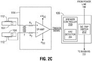
- FIG. 2C shows yet another exemplary signal conditioner circuit 114 according to embodiments of the present disclosure.
- the signal conditioner circuit 114 in this example also employs an op-amp in a typical differential amplifier configuration, with non-inverting and inverting inputs connected respectively through resistors R1 and R2 to a pair of sensors 112.
- the sensors 112 in this embodiment are connected to the op-amp inputs via a transformer T for isolation purposes. Operation of this op-amp is otherwise the same as operation of the op-amp in the embodiment of FIG. 2B .
- a shielded twisted-pair cable can be used to provide the connection from the sensors 112 to the op-amp inputs, whether directly ( FIGS. 2A-2B ) or indirectly ( FIG. 2C ), to reduce electromagnetic interference.
- FIG. 3A illustrates an exemplary load center 300 where, instead of capacitive sensors like the sensors 112, a radio frequency (RF) transceiver 302 is used to monitor arc formation in the branch breakers 104.
- RF radio frequency
- These embodiments take advantage of radio frequency energy 304 being present in the electromagnetic field emitted by an arc to detect arc formation.
- the RF transceiver 302 can be mounted directly on the load center 300 or as a separate module within detectable range of the load center 300.
- Suitable commercially available RF transceivers that may be used in these embodiments include the MRF89XA integrated ultra-low-power sub-GHz transceiver from Microchip Technology, Inc., of Chandler, Arizona.
- Such a transceiver 302 typically has one or more integrated antennas and associated circuitry that can detect or otherwise pick up radio frequency energy 304 from the arc and output a signal proportional to the radio frequency energy.
- the signal may then be sent as a trigger signal to the main breaker 106 to detect arc formation within the branch breakers 104.
- the trigger signal is sent to the main breaker 106 over a wired (e.g., shielded twisted-pair) connection 306.
- FIG. 3B illustrates an alternative embodiment of the exemplary load center 300 in which the RF transceiver 302 transmits the trigger signal over a wireless connection 308 to the main breaker 106.
- the wireless connection 308 may be any suitable short to medium range wireless connection, such as Wi-Fi, Bluetooth, LowPan6, WirelessHART, Zigbee, SigFox, RPMA, and the like.
- the main breaker 106 would of course need to include an appropriate wireless interface (not expressly shown) that can receive such a transmitted trigger signal.
- the main breaker 106 processes the trigger signal to determine whether the signal satisfies a predefined condition indicative of arc formation (e.g., matches a certain pattern and/or shape, exceeds a certain amplitude and/or duration, etc.).
- a predefined condition indicative of arc formation e.g., matches a certain pattern and/or shape, exceeds a certain amplitude and/or duration, etc.
- the predefined condition may be derived, for example, by tripping one of the branch breakers 104 in a controlled setting and analyzing the resulting signal generated by the RF transceiver 302.
- FIG. 3C illustrates yet another alternative embodiment of the exemplary load center 300 where arc suppression is performed without checking for arc formation.
- electronic trip circuit breakers 310 are used as the branch breakers. These electronic trip breakers 310 employ a programmable trip unit instead of a bimetallic strip or the like to detect a fault condition and actuate a trip mechanism.
- the programmable trip unit is typically a microprocessor, microcontroller, ASIC, or other suitable controllers known to those skilled in the art.
- Commercially available electronic trip breakers that may be used in this embodiment include breakers equipped with the Micrologic Trip System from Schneider Electric USA, Inc., of Boston, Massachusetts.
- logic within the trip unit of the electronic trip circuit breakers 310 detects the fault condition and outputs a trip signal that actuates the trip mechanism.
- This trip signal may be tapped and sent as a trigger signal to the main breaker 106 over a suitable connection 312 (e.g., shielded twisted-pair).
- the main breaker 106 Upon receiving the trip/trigger signal, the main breaker 106 again checks whether signal meets a predefined conditioned before cutting current flow.
- the predefined condition can be simply whether the trip/trigger signal satisfies a predefined logic level, such as a logic high (or low) level. The main breaker 106 does not need to determine whether the signal satisfies a predefined condition indicative of arc formation before cutting current flow.
- the flowchart 400 generally begins at block 402 where a main breaker monitors the load center for receipt of a trigger signal.
- the trigger signal is provided to the main breaker by one or more sensors mounted on or near the load center or the branch breakers therein.
- the trigger signal is provided to the main breaker directly by one of the branch breakers in the load center.
- sensors may include capacitive sensors, RF sensors, and other types of sensors that can detect arc formation within the branch breakers.
- the main breaker Upon receipt of the trigger signal, the main breaker determines whether the trigger signal satisfies a predefined condition at block 404.
- the predefined condition is indicative of arc formation, such as whether the signal has a waveform that resembles a certain pattern and/or shape, whether the signal exceeds a certain amplitude, duration, and/or other threshold, and the like. In other embodiments, the predefined condition is a certain logic level. If the determination is no, then main breaker returns to block 402 and continues to monitor the load center for receipt of the trigger signal.
- the main breaker temporarily interrupts current flow to the busbars in the load center at block 406.
- the main breaker thereafter waits at block 408 for occurrence of a predefined event, such as an immediately next zero-crossing of the load center voltage, a fixed amount of time, such as a half cycle of the load center current, and the like. In either case, the wait period should be long enough to allow the tripped branch breaker to clear, but short enough to avoid adversely affecting the electronic devices on other branch breakers.
- the main breaker restores current flow to the busbars of the load center at block 410, and returns to block 402 for continued monitoring of the branch breakers.
- FIG. 5A-5B are current and voltage plots illustrating exemplary arc suppression in a load center according to some embodiments of the present disclosure.
- the vertical axis represents amplitude
- the horizontal axis represents time
- the origin represents opening of the current-carrying contacts of a branch breaker.
- plot 500 shows a branch breaker arc current 502 and a branch breaker arc voltage 504 in which no arc suppression is performed by the main breaker.
- current 502 continues to flow shortly after opening of the current-carrying contacts of the branch breaker due to an arc forming between the contacts.
- the arc has an energy that is represented by the shaded area 506 under voltage 504.
- This arc energy 506 is fed by current 502 until the current-carrying contacts eventually move too far apart for the arc to be sustained and dissipates, at which point current 502 goes to zero.
- plot 510 shows a branch breaker arc current 502' and a branch breaker arc voltage 504' in which arc suppression is performed by the main breaker according to embodiments of the present disclosure.
- current 502' continues to flow shortly after opening of the current-carrying contacts of the branch breaker due to an arc being formed between the contacts.
- the arc formation is detected as described above by the main breaker, which quickly cuts off current flow at 512. Without current flow to sustain it, the arc rapidly dissipates, thus significantly reducing the amount of arc energy 506' compared to the arc energy 506 shown in FIG. 5A .
- the main breaker thereafter waits a brief time period to allow the branch breaker to clear at 514, then restores current flow at the next voltage zero-crossing at 516.
- aspects disclosed herein may be implemented as a system, method or computer program product. Accordingly, aspects may take the form of an entirely hardware embodiment, an entirely software embodiment (including firmware, resident software, micro-code, etc.) or an embodiment combining software and hardware aspects that may all generally be referred to as a "circuit,” “module” or “system.” Furthermore, aspects may take the form of a computer program product embodied in one or more computer-readable medium(s) having computer-readable program code embodied thereon.
- the computer-readable medium may be a non-transitory computer-readable medium.
- a non-transitory computer-readable medium may be, for example, but not limited to, an electronic, magnetic, optical, electromagnetic, infrared, or semiconductor system, apparatus, or device, or any suitable combination of the foregoing.
- non-transitory computer-readable medium can include the following: an electrical connection having one or more wires, a portable computer diskette, a hard disk, a random access memory (RAM), a read-only memory (ROM), an erasable programmable read-only memory (EPROM or Flash memory), an optical fiber, a portable compact disc read-only memory (CD-ROM), an optical storage device, a magnetic storage device, or any suitable combination of the foregoing.
- Program code embodied on a computer-readable medium may be transmitted using any appropriate medium, including but not limited to wireless, wireline, optical fiber cable, RF, etc., or any suitable combination of the foregoing.
- Computer program code for carrying out operations for aspects of the present disclosure may be written in any combination of one or more programming languages. Moreover, such computer program code can execute using a single computer system or by multiple computer systems communicating with one another (e.g., using a local area network (LAN), wide area network (WAN), the Internet, etc.). While various features in the preceding are described with reference to flowchart illustrations and/or block diagrams, a person of ordinary skill in the art will understand that each block of the flowchart illustrations and/or block diagrams, as well as combinations of blocks in the flowchart illustrations and/or block diagrams, can be implemented by computer logic (e.g., computer program instructions, hardware logic, a combination of the two, etc.).
- computer logic e.g., computer program instructions, hardware logic, a combination of the two, etc.
- computer program instructions may be provided to a processor(s) of a general-purpose computer, special-purpose computer, or other programmable data processing apparatus. Moreover, the execution of such computer program instructions using the processor(s) produces a machine that can carry out a function(s) or act(s) specified in the flowchart and/or block diagram block or blocks.
- each block in the flowchart or block diagrams may represent a module, segment or portion of code, which comprises one or more executable instructions for implementing the specified logical function(s).
- the functions noted in the block may occur out of the order noted in the figures. For example, two blocks shown in succession may, in fact, be executed substantially concurrently, or the blocks may sometimes be executed in the reverse order, depending upon the functionality involved.
Landscapes
- Physics & Mathematics (AREA)
- General Physics & Mathematics (AREA)
- Emergency Protection Circuit Devices (AREA)
Abstract
Description
- The present disclosure relates to electrical distribution panels and load centers and, more particularly, to methods and systems for implementing load centers that can detect and suppress arc formation in branch circuit breakers without adversely affecting other devices connected to the load centers.
- Arcing refers to an electrical discharge through a normally nonconductive gas, usually air. In a load center, arcing can occur between any exposed conductors of different electrical potentials, such as between adjacent busbars or a busbar and ground, as well as between current-carrying contacts in the branch circuit breakers. When a branch breaker trips and the current-carrying contacts start to separate, an arc can form across the air gap between the two contacts as current continues flowing until the contacts attain sufficient separation.
- Arcing can produce extremely hot gasses, vaporized metals/polymers, and other harmful byproducts. These arc byproducts can damage circuit breaker components, causing them to wear out more quickly than usual, and even rendering the breakers no longer operational in some cases. As a result, circuit breakers are required to be constructed from heavier and stronger materials and have bigger casings in order to provide a large enough contact chamber to satisfy industry standards and ratings requirements.
- Accordingly, as can be readily appreciated, improvements are needed in the field of electrical distribution panels and load centers, particularly with respect to arcing in the branch breakers of such load centers.
- The present disclosure provides methods and systems for implementing electrical distribution panels and load centers that can detect and suppress arc formation in branch breakers. The methods and systems provide a load center that is equipped to monitor a branch breaker for indications of an arc being formed. The load center may include a main breaker that can immediately cut current flow upon receiving an indication of an arc forming in a branch breaker. The indication may be provided by a sensor mounted on or near the branch breaker that sends a trigger signal to the main breaker when arc formation is detected within the branch breaker. The main breaker then determines whether the trigger signal satisfies a certain condition or conditions indicative of arc formation. If so, the main breaker cuts current flow to suppress the arc, then waits a short period of time while the branch breaker clears before restoring current flow. The wait period is preferably short enough such that devices receiving power from the load center are not adversely affected by the interruption in current flow. To improve current cutoff and restoration response times, the main breaker employs a solid-state trip switch capable of extremely fast switching times.
- In general, in one aspect, embodiments of the present disclosure relate to a load center. The load center comprises, among other things, a plurality of branch breakers, and at least one sensor coupled to the plurality of branch breakers. The at least one sensor is configured to sense a parameter indicative of arc formation in one of the branch breakers. The load center further comprises a solid-state main breaker coupled to receive a trigger signal from the at least one sensor. The solid-state main breaker is configured to determine whether the trigger signal satisfies a predefined arcing condition and, in response, temporarily interrupt current flow to the plurality of branch breakers and wait for a predefined event before restoring current flow to the plurality of branch breakers.
- In accordance with any one or more of the foregoing embodiments, the at least one sensor comprises one sensor coupled to each of the plurality of branch breakers or one sensor coupled to multiple ones of the plurality of branch breakers.
- In accordance with any one or more of the foregoing embodiments, the at least one sensor includes a voltage sensor and the parameter is voltage induced by arc formation in one of the branch breakers, and the load center further comprises a signal conditioning circuit connected to the voltage sensor, or the at least one sensor includes a radio frequency sensor and the parameter is radio frequency energy generated by arc formation in one of the branch breakers.
- In accordance with any one or more of the foregoing embodiments, the predefined event is one of a predefined time period or an immediately next zero-crossing of a load center voltage, and the predefined time period is a half cycle of a load center current.
- In general, in another aspect, embodiments of the present disclosure relate to a main breaker for a load center. The main breaker comprises, among other things, a solid-state trip switch configured to provide current flow to a plurality of branch breakers, and a breaker controller configured to control switching of the solid-state trip switch. The breaker controller is operable to receive a trigger signal resulting from a fault condition in one of the branch breakers and determine whether the trigger signal satisfies a predefined condition. The breaker controller is further operable to temporarily interrupt current flow to the branch breakers and wait for a predefined event before restoring current flow to the branch breakers in response the trigger signal satisfying the predefined condition.
- In accordance with any one or more of the foregoing embodiments, the predefined condition is one of a predefined logic level or a predefined arcing condition, and the predefined arcing condition includes the trigger signal having one or more of a predefined waveform, shape, amplitude, and duration.
- In accordance with any one or more of the foregoing embodiments, the trigger signal is received from at least one sensor coupled the branch breakers and represents one of a voltage induced by arc formation in one of the branch breakers or radio frequency energy generated by arc formation in one of the branch breakers.
- In accordance with any one or more of the foregoing embodiments, the predefined event is one of a predefined time period or an immediately next zero-crossing of a main breaker voltage, and the predefined time period is a half cycle of a main breaker current.
- In general, in yet another aspect, embodiments of the present disclosure relate to a method of suppressing arc formation in a load center. The method comprises, among other things, receiving, at a main breaker, a trigger signal resulting from a fault condition in one of a plurality of branch breakers in the load center, and determining, at the main breaker, whether the trigger signal satisfies a predefined condition. The method further comprises temporarily interrupting, at the main breaker, current flow to the plurality of branch breakers in response to the trigger signal satisfying the predefined condition, and restoring, at the main breaker, current flow to the plurality of branch breakers after occurrence of a predefined event.
- In accordance with any one or more of the foregoing embodiments, the method further comprises coupling a sensor to each of the plurality of branch breakers or coupling at least one sensor to multiple ones of the plurality of branch breakers.
- In accordance with any one or more of the foregoing embodiments, the predefined condition is one of a predefined logic level or a predefined arcing condition, and the predefined arcing condition includes the trigger signal having one or more of a predefined waveform, shape, amplitude, and duration.
- In accordance with any one or more of the foregoing embodiments, the trigger signal is received from at least one sensor coupled the branch breakers, further comprising conditioning the trigger signal at a signal conditioning circuit connected to the at least one sensor.
- In accordance with any one or more of the foregoing embodiments, the trigger signal represents one of a voltage induced by arc formation in one of the branch breakers or radio frequency energy generated by arc formation in one of the branch breakers.
- In accordance with any one or more of the foregoing embodiments, the predefined event is one of a time period equal to a half cycle of a load center current, or an immediately next zero-crossing of a load center voltage.
- A more detailed description of the disclosure, briefly summarized above, may be had by reference to various embodiments, some of which are illustrated in the appended drawings. While the appended drawings illustrate select embodiments of this disclosure, these drawings are not to be considered limiting of its scope, for the disclosure may admit to other equally effective embodiments.
-
FIGS. 1A-1C are schematic diagrams illustrating exemplary load centers that can suppress arc formation in branch circuit breakers according to embodiments of the present disclosure; -
FIGS. 2A-2C are block diagrams illustrating exemplary sensor circuits that can detect arc formation in branch circuit breakers according to embodiments of the present disclosure; -
FIGS. 3A-3C are schematic diagrams illustrating exemplary alternative load centers that can suppress arc formation in branch circuit breakers according to embodiments of the present disclosure; -
FIG. 4 is a flow diagram illustrating a method of suppressing arcing in a load center according to embodiments of the present disclosure; and -
FIGS. 5A-5B are current and voltage plots illustrating exemplary arc suppression in a load center according to embodiments of the present disclosure. - Identical reference numerals have been used, where possible, to designate identical elements that are common to the figures. However, elements disclosed in one embodiment may be beneficially utilized on other embodiments without specific recitation.
- Referring now to
FIG. 1 , an exemplary building orfacility 100 is shown having one or more electrical distribution panels orload centers 102 that can suppress arc formation in branch breakers according to embodiments of the present disclosure. Thefacility 100 may be any facility where load centers like theload centers 102 are deployed, such as a chemical processing facility, a manufacturing facility, a warehouse facility, and the like. These facilities typically include various electronic devices, machinery, and equipment that rely on continuous current flow from theload centers 102 to operate properly. An interruption in current flow of sufficient duration can cause these devices to abruptly shut down, which can result in equipment damage, loss and/or corrupted data, various safety hazards, and the like, potentially leading to expensive and lengthy recovery and repair. Accordingly, the one ormore load centers 102 disclosed herein are designed to minimally interrupt current flow when performing arc suppression to avoid adversely affecting these electronic devices. - As
FIG. 1A shows, eachload center 102 includes a plurality ofbranch circuit breakers 104 and amain circuit breaker 106 that provide fault (e.g., short-circuit, overcurrent, etc.) protection for various electronic devices powered by theload center 102. Themain breaker 106 protects theoverall load center 102 while eachbranch breaker 104 protects one of several branch circuits (not expressly shown) that extend throughout thebuilding 100. Current flows from an ACmain power line 108 into themain breaker 106 downbusbars 110 and out through thebranch breakers 104. A trip switch in themain breaker 106 connects/disconnects thepower line 108 to/from thebusbars 110. Themain breaker 106 controls this trip switch to automatically cut current flow to thebusbars 110 when a fault occurs, and otherwise allows the current to flow through thebusbars 110. - In the
FIG. 1A example, each of thebranch breakers 104 has asensor 112 attached to or near an outer casing of the breaker that allows themain breaker 106 to monitor arc formation within the breaker. An arc emits a strong electromagnetic field that can be detected by various types of sensors known to those skilled in the art. One sensor that may be used to detect an arc within thebreaker 104 is an E-Dot sensor, which is a type of capacitive sensor. The E-Dot sensor uses a circular plate made of a suitably conductive material, such as copper, to detect an electromagnetic field. When the plate nears an electromagnetic field like that generated by an arc, the field time rate of change (dE/dt) induces a voltage in the plate that can be outputted as a signal. The signal serves as a trigger signal that is indicative of arc formation within thebreaker 104 for purposes of the present disclosure. Other types of sensors may of course be used within the scope of the present disclosures. - In general operation, when an arc begins to form in one of the branch breakers 104 (i.e., because that breaker has tripped), the
sensor 112 for that breaker detects the electromagnetic field generated by the arc and outputs a corresponding signal. This trigger signal is then conditioned (e.g., smoothed, filtered, amplified, etc.) by asignal conditioner circuit 114 as needed, then sent to themain breaker 106 for further processing. Themain breaker 106 processes the trigger signal to determine whether the signal satisfies a predefined condition that indicates arc formation. The determination may include, for example, whether the signal has a waveform that resembles a certain pattern and/or shape, whether the signal exceeds a certain amplitude, duration, and/or other threshold, and the like. If the trigger signal satisfies the condition or conditions indicative of arc formation, themain breaker 106 cuts current flow to thebusbars 110 by opening the trip switch to thepower line 108. Without current flow to sustain it, the arc loses energy and quickly dissipates, resulting in significantly less damage to thebranch breaker 104 than would otherwise occur. - After a brief wait period, the
main breaker 106 closes the trip switch for thepower line 108 to restore current flow to thebusbars 110. As alluded to earlier, the time period that themain breaker 106 waits before restoring current flow is long enough to allow the trippedbranch breaker 104 to clear, but short enough to avoid adversely affecting electronic devices on other branch breakers 104 (e.g., causing the devices to abruptly shut down). In some embodiments, themain breaker 106 bases this wait period on a predefined event, such as an immediately next zero-crossing of the load center voltage, a fixed amount of time (e.g., a half cycle of the load center current), and other predefined events that are suitably short to avoid adversely affecting electronic devices. In preferred embodiments, the wait period is less than 8 milliseconds (msec), as a current loss of less than 8 msec does not adversely affect most electronic devices. - The
main breaker 106 needs to have extremely fast switching times in order to perform the above current flow interruption, wait period, and restoration. Therefore, in preferred embodiments, themain breaker 106 is a type of breaker that uses a solid-state trip switch, such as a silicon carbide (SiC) transistor-based trip switch. Silicon carbide transistors, such as SiC MOSFET and Si CoolMOS, have extremely fast switching times (e.g., tswitch < 1 µsec) and low drain-source resistance (e.g., Rds(on) < 1 mΩ) at full current load, and thus are well suited for use as a main breaker in the load center embodiments herein. Commercially available examples include solid-state digital circuit breakers available from Atom Power, Inc., of Charlotte, North Carolina. These Atom Power intelligent digital circuit breakers can reportedly switch up to several thousand times faster than conventional thermal-mechanical circuit breakers. - Conventional thermal-mechanical circuit breakers, on the other hand, are well suited for use as the
branch breakers 104, which do not require sub-microsecond switching times for normal operations. Examples include molded case circuit breakers (MCCB), miniature circuit breakers (MCB), and other commonly-used load center circuit breakers. Indeed, in alternative embodiments of theload center 102, thebranch breakers 104 need not be breakers at all, but may instead resemble simple relay switches. Such simple relay switches only need to satisfy switching duty ratings (e.g., 120V/240V, 15A, 20A, etc.), as fault protection and other more traditional breaker functionality could be provided by themain breaker 106. Preferably the relay switches are remotely operable to allow them to be set/reset via a wired or wireless connection, an Internet connection, or other remote connections. -
FIG. 1B depicts another alternative embodiment of theload center 102 in which themain breaker 106 uses onesensor 112 to monitormultiple branch breakers 104 instead of asingle breaker 104. This reduces the number ofsensors 112 that need to be mounted within theload center 102, with the specific number ofsensors 112 used being chosen as needed depending on a particular application. Eachsensor 112 should of course have sufficient sensitivity to detect arc formation within one or severalnearby breakers 104 without being directly attached to the breakers. Signal conditioner circuits (not expressly shown) may be provided to condition the output signals from thesensors 112 as warranted. -
FIG. 1C depicts yet anotheralternative load center 102 embodiment in which themain breaker 106 is mounted separately from instead of within theload center 102. For example, themain breaker 106 may be mounted at a different location in the same utility room as theload center 102, or in a separate utility room, or in another part of thefacility 100, and the like. As well, in this embodiment, themain breaker 106 uses stillfewer sensors 112 than the embodiment ofFIG. 1B to monitor arc formation in thebranch breakers 104. For example, there may be asensor 112 mounted only at opposite ends for each row ofbranch breakers 104. Again, signal conditioner circuits (not expressly shown) may be provided to condition the output signals from thesensors 112 as needed. - An exemplary
signal conditioner circuit 114 is shown inFIG. 2A together with an exemplarymain breaker 106 according to embodiments of the present disclosure. Thesignal conditioner circuit 114 in this example is a typical single-ended amplifier circuit composed of an operational amplifier (op-amp) connected as shown. Specifically, the op-amp non-inverting input is connected to onesensor 112, while the inverting input is tied to a fixed threshold voltage Vthres. The threshold voltage Vthres is set by a voltage divider network composed of resistors R1 and R2 and may be selected as needed depending on the particular application. Capacitors C1 and C2 provide smoothing for the op-amp positive voltage supply +Vcc, while the op-amp negative voltage supply is grounded along with asecond sensor 112. Suitable commercially available op-amps that may be used in this embodiment include the LM339 op-amp from Texas Instruments, Inc., of Dallas, Texas. These LM339 op-amps and similar op-amps typically come in sufficiently small packages to allow thesignal conditioner circuit 114 to be mounted within one of thebranch breakers 104. - The above
signal conditioner circuit 114 operates to amplify any voltage at the op-amp non-inverting input (i.e., from sensor 112) and outputs the amplified signal as a trigger signal to themain breaker 106. Themain breaker 106, as discussed above, comes from a line of solid-state digital circuit breakers with extremely fast switching times. These intelligent digital breakers typically have abreaker controller 200 and a silicon-carbide transistor-basedtrip switch 202, among other components. Thebreaker controller 200 is programmed to provide various breaker functionality, including current and voltage monitoring, fault detection, and the like. When a fault condition is detected, such as a short-circuit or an overcurrent, thebreaker controller 200 outputs a command to thetrip switch 202 to shut off current flow to the busbars 110 (e.g., by turning off one or more transistors that form the trip switch). - In accordance with embodiments of the present disclosure, the
breaker controller 200 may also be programmed with anarc detector module 204 that provides arc detection functionality. When the trigger signal is received by thebreaker controller 200, thearc detector module 204 determines whether the trigger signal satisfies a predefined condition indicative of arc formation (e.g., matches a certain pattern and/or shape, exceeds a certain amplitude and/or duration, etc.). Such a predefined condition may be derived, for example, by tripping one of thebranch breakers 104 in a controlled setting and analyzing the resulting signal generated by thesensor 112 andsignal conditioner circuit 114. If the trigger signal satisfies the condition or conditions that indicate arc formation, then thearc detector module 204 causes thebreaker controller 200 to interrupt current flow to thebusbars 110. Thedetector module 204 thereafter causes thebreaker controller 200 to wait for occurrence of a predefined event (e.g., next voltage zero-crossing, time interval of a current half cycle, etc.), then restore current flow to the busbars 110 (e.g., by turning on one or more transistors that form the trip switch). -
FIG. 2B shows another exemplarysignal conditioner circuit 114 according to embodiments of the present disclosure. Thesignal conditioner circuit 114 in this example is a typical differential amplifier circuit composed of an op-amp with non-inverting and inverting inputs connected as shown through resistors R1 and R2, respectively, to a pair ofsensors 112. When connected thusly, the op-amp amplifies any difference that may arise in the voltages from the twosensors 112, for example, due to arc formation in one of thebranch breakers 104. The op amp then outputs the amplified difference as a trigger signal to themain breaker 106 to detect the arc formation. An advantage of the differential amplifier circuit over the single-ended amplifier circuit is that the differential amplifier provides better noise reduction, although the signal level may be more reduced. Suitable commercially available op-amps that may be used in this embodiment include the TLV1805 high-voltage op-amp from Texas Instruments. -
FIG. 2C shows yet another exemplarysignal conditioner circuit 114 according to embodiments of the present disclosure. Thesignal conditioner circuit 114 in this example also employs an op-amp in a typical differential amplifier configuration, with non-inverting and inverting inputs connected respectively through resistors R1 and R2 to a pair ofsensors 112. However, thesensors 112 in this embodiment are connected to the op-amp inputs via a transformer T for isolation purposes. Operation of this op-amp is otherwise the same as operation of the op-amp in the embodiment ofFIG. 2B . In these and other embodiments discussed herein, a shielded twisted-pair cable can be used to provide the connection from thesensors 112 to the op-amp inputs, whether directly (FIGS. 2A-2B ) or indirectly (FIG. 2C ), to reduce electromagnetic interference. -
FIG. 3A illustrates anexemplary load center 300 where, instead of capacitive sensors like thesensors 112, a radio frequency (RF)transceiver 302 is used to monitor arc formation in thebranch breakers 104. These embodiments take advantage ofradio frequency energy 304 being present in the electromagnetic field emitted by an arc to detect arc formation. TheRF transceiver 302 can be mounted directly on theload center 300 or as a separate module within detectable range of theload center 300. Suitable commercially available RF transceivers that may be used in these embodiments include the MRF89XA integrated ultra-low-power sub-GHz transceiver from Microchip Technology, Inc., of Chandler, Arizona. Such atransceiver 302 typically has one or more integrated antennas and associated circuitry that can detect or otherwise pick upradio frequency energy 304 from the arc and output a signal proportional to the radio frequency energy. The signal may then be sent as a trigger signal to themain breaker 106 to detect arc formation within thebranch breakers 104. In the embodiment shown, the trigger signal is sent to themain breaker 106 over a wired (e.g., shielded twisted-pair)connection 306. -
FIG. 3B illustrates an alternative embodiment of theexemplary load center 300 in which theRF transceiver 302 transmits the trigger signal over awireless connection 308 to themain breaker 106. Thewireless connection 308 may be any suitable short to medium range wireless connection, such as Wi-Fi, Bluetooth, LowPan6, WirelessHART, Zigbee, SigFox, RPMA, and the like. Themain breaker 106 would of course need to include an appropriate wireless interface (not expressly shown) that can receive such a transmitted trigger signal. In either case, themain breaker 106 processes the trigger signal to determine whether the signal satisfies a predefined condition indicative of arc formation (e.g., matches a certain pattern and/or shape, exceeds a certain amplitude and/or duration, etc.). As with previous embodiments, the predefined condition may be derived, for example, by tripping one of thebranch breakers 104 in a controlled setting and analyzing the resulting signal generated by theRF transceiver 302. -
FIG. 3C illustrates yet another alternative embodiment of theexemplary load center 300 where arc suppression is performed without checking for arc formation. In this embodiment, instead of conventional thermal-mechanical breakers, electronictrip circuit breakers 310 are used as the branch breakers. Theseelectronic trip breakers 310 employ a programmable trip unit instead of a bimetallic strip or the like to detect a fault condition and actuate a trip mechanism. The programmable trip unit is typically a microprocessor, microcontroller, ASIC, or other suitable controllers known to those skilled in the art. Commercially available electronic trip breakers that may be used in this embodiment include breakers equipped with the Micrologic Trip System from Schneider Electric USA, Inc., of Boston, Massachusetts. - When a fault condition occurs, logic within the trip unit of the electronic
trip circuit breakers 310 detects the fault condition and outputs a trip signal that actuates the trip mechanism. This trip signal may be tapped and sent as a trigger signal to themain breaker 106 over a suitable connection 312 (e.g., shielded twisted-pair). Upon receiving the trip/trigger signal, themain breaker 106 again checks whether signal meets a predefined conditioned before cutting current flow. In this embodiment, the predefined condition can be simply whether the trip/trigger signal satisfies a predefined logic level, such as a logic high (or low) level. Themain breaker 106 does not need to determine whether the signal satisfies a predefined condition indicative of arc formation before cutting current flow. Indeed, depending on the particular implementation, it may be possible for current flow to be cut even before the current-carrying contacts of the trip mechanism begin to separate (i.e., before arc formation can begin). Such an arrangement allows themain breaker 106 to perform a type of preemptive suppressing of arc formation. - Thus far, the embodiments disclosed herein have been described with respect to an electrical distribution panel or load center. However, the principles and teachings discussed herein are equally applicable to other types of electrical distribution arrangements, such as a motor control center (MCC), switchgear, and the like. It should therefore be understood that other types of electrical distribution arrangements besides load centers are within the scope of the present disclosure.
- Referring now to
FIG. 4 , anexemplary flowchart 400 is shown representing a method that may be used to suppress arc formation in a load center according to embodiments of the present disclosure. Theflowchart 400 generally begins atblock 402 where a main breaker monitors the load center for receipt of a trigger signal. In some embodiments, the trigger signal is provided to the main breaker by one or more sensors mounted on or near the load center or the branch breakers therein. In other embodiments, the trigger signal is provided to the main breaker directly by one of the branch breakers in the load center. Where sensors are used, such sensors may include capacitive sensors, RF sensors, and other types of sensors that can detect arc formation within the branch breakers. - Upon receipt of the trigger signal, the main breaker determines whether the trigger signal satisfies a predefined condition at
block 404. In some embodiments, the predefined condition is indicative of arc formation, such as whether the signal has a waveform that resembles a certain pattern and/or shape, whether the signal exceeds a certain amplitude, duration, and/or other threshold, and the like. In other embodiments, the predefined condition is a certain logic level. If the determination is no, then main breaker returns to block 402 and continues to monitor the load center for receipt of the trigger signal. - If the determination is yes, then the main breaker temporarily interrupts current flow to the busbars in the load center at
block 406. The main breaker thereafter waits atblock 408 for occurrence of a predefined event, such as an immediately next zero-crossing of the load center voltage, a fixed amount of time, such as a half cycle of the load center current, and the like. In either case, the wait period should be long enough to allow the tripped branch breaker to clear, but short enough to avoid adversely affecting the electronic devices on other branch breakers. Upon occurrence of the predefined event, the main breaker restores current flow to the busbars of the load center atblock 410, and returns to block 402 for continued monitoring of the branch breakers. -
FIG. 5A-5B are current and voltage plots illustrating exemplary arc suppression in a load center according to some embodiments of the present disclosure. In these plots, the vertical axis represents amplitude, the horizontal axis represents time, and the origin represents opening of the current-carrying contacts of a branch breaker. - Referring first to
FIG. 5A ,plot 500 shows a branch breaker arc current 502 and a branchbreaker arc voltage 504 in which no arc suppression is performed by the main breaker. As can be seen, current 502 continues to flow shortly after opening of the current-carrying contacts of the branch breaker due to an arc forming between the contacts. The arc has an energy that is represented by the shadedarea 506 undervoltage 504. Thisarc energy 506 is fed by current 502 until the current-carrying contacts eventually move too far apart for the arc to be sustained and dissipates, at which point current 502 goes to zero. - In
FIG. 5B ,plot 510 shows a branch breaker arc current 502' and a branch breaker arc voltage 504' in which arc suppression is performed by the main breaker according to embodiments of the present disclosure. As before, current 502' continues to flow shortly after opening of the current-carrying contacts of the branch breaker due to an arc being formed between the contacts. Here, however, the arc formation is detected as described above by the main breaker, which quickly cuts off current flow at 512. Without current flow to sustain it, the arc rapidly dissipates, thus significantly reducing the amount of arc energy 506' compared to thearc energy 506 shown inFIG. 5A . The main breaker thereafter waits a brief time period to allow the branch breaker to clear at 514, then restores current flow at the next voltage zero-crossing at 516. - In the preceding, reference is made to various embodiments. However, the scope of the present disclosure is not limited to the specific described embodiments. Instead, any combination of the described features and elements, whether related to different embodiments or not, is contemplated to implement and practice contemplated embodiments. Furthermore, although embodiments may achieve advantages over other possible solutions or over the prior art, whether or not a particular advantage is achieved by a given embodiment is not limiting of the scope of the present disclosure. Thus, the preceding aspects, features, embodiments and advantages are merely illustrative and are not considered elements or limitations of the appended claims except where explicitly recited in a claim(s).
- The various embodiments disclosed herein may be implemented as a system, method or computer program product. Accordingly, aspects may take the form of an entirely hardware embodiment, an entirely software embodiment (including firmware, resident software, micro-code, etc.) or an embodiment combining software and hardware aspects that may all generally be referred to as a "circuit," "module" or "system." Furthermore, aspects may take the form of a computer program product embodied in one or more computer-readable medium(s) having computer-readable program code embodied thereon.
- Any combination of one or more computer-readable medium(s) may be utilized. The computer-readable medium may be a non-transitory computer-readable medium. A non-transitory computer-readable medium may be, for example, but not limited to, an electronic, magnetic, optical, electromagnetic, infrared, or semiconductor system, apparatus, or device, or any suitable combination of the foregoing. More specific examples (a non-exhaustive list) of the non-transitory computer-readable medium can include the following: an electrical connection having one or more wires, a portable computer diskette, a hard disk, a random access memory (RAM), a read-only memory (ROM), an erasable programmable read-only memory (EPROM or Flash memory), an optical fiber, a portable compact disc read-only memory (CD-ROM), an optical storage device, a magnetic storage device, or any suitable combination of the foregoing. Program code embodied on a computer-readable medium may be transmitted using any appropriate medium, including but not limited to wireless, wireline, optical fiber cable, RF, etc., or any suitable combination of the foregoing.
- Computer program code for carrying out operations for aspects of the present disclosure may be written in any combination of one or more programming languages. Moreover, such computer program code can execute using a single computer system or by multiple computer systems communicating with one another (e.g., using a local area network (LAN), wide area network (WAN), the Internet, etc.). While various features in the preceding are described with reference to flowchart illustrations and/or block diagrams, a person of ordinary skill in the art will understand that each block of the flowchart illustrations and/or block diagrams, as well as combinations of blocks in the flowchart illustrations and/or block diagrams, can be implemented by computer logic (e.g., computer program instructions, hardware logic, a combination of the two, etc.). Generally, computer program instructions may be provided to a processor(s) of a general-purpose computer, special-purpose computer, or other programmable data processing apparatus. Moreover, the execution of such computer program instructions using the processor(s) produces a machine that can carry out a function(s) or act(s) specified in the flowchart and/or block diagram block or blocks.
- The flowchart and block diagrams in the Figures illustrate the architecture, functionality and/or operation of possible implementations of various embodiments of the present disclosure. In this regard, each block in the flowchart or block diagrams may represent a module, segment or portion of code, which comprises one or more executable instructions for implementing the specified logical function(s). It should also be noted that, in some alternative implementations, the functions noted in the block may occur out of the order noted in the figures. For example, two blocks shown in succession may, in fact, be executed substantially concurrently, or the blocks may sometimes be executed in the reverse order, depending upon the functionality involved. It will also be noted that each block of the block diagrams and/or flowchart illustration, and combinations of blocks in the block diagrams and/or flowchart illustration, can be implemented by special purpose hardware-based systems that perform the specified functions or acts, or combinations of special purpose hardware and computer instructions.
- It is to be understood that the above description is intended to be illustrative, and not restrictive. Many other implementation examples are apparent upon reading and understanding the above description. Although the disclosure describes specific examples, it is recognized that the systems and methods of the disclosure are not limited to the examples described herein, but may be practiced with modifications within the scope of the appended claims. Accordingly, the specification and drawings are to be regarded in an illustrative sense rather than a restrictive sense. The scope of the disclosure should, therefore, be determined with reference to the appended claims, along with the full scope of equivalents to which such claims are entitled.
Claims (20)
- A load center, comprising:a plurality of branch breakers;at least one sensor coupled to the plurality of branch breakers, the at least one sensor configured to sense a parameter indicative of arc formation in one of the branch breakers; anda solid-state main breaker coupled to receive a trigger signal from the at least one sensor, the solid-state main breaker configured to determine whether the trigger signal satisfies a predefined arcing condition and, in response, temporarily interrupt current flow to the plurality of branch breakers and wait for a predefined event before restoring current flow to the plurality of branch breakers.
- The load center of claim 1, wherein the at least one sensor comprises one sensor coupled to each of the plurality of branch breakers.
- The load center of claim 1 or 2, wherein the at least one sensor comprises one sensor coupled to multiple ones of the plurality of branch breakers.
- The load center of any of the preceding claims, wherein the at least one sensor includes a voltage sensor and the parameter is voltage induced by arc formation in one of the branch breakers, and the load center further comprises a signal conditioning circuit connected to the voltage sensor.
- The load center of any of the preceding claims, wherein the at least one sensor includes a radio frequency sensor and the parameter is radio frequency energy generated by arc formation in one of the branch breakers.
- The load center of any of the preceding claims, wherein the predefined event is one of: a predefined time period, or an immediately next zero-crossing of a load center voltage.
- The load center of claim 6, wherein the predefined time period is a half cycle of a load center current.
- A main breaker for a load center, comprising:a solid-state trip switch configured to provide current flow to a plurality of branch breakers; anda breaker controller configured to control switching of the solid-state trip switch, the breaker controller operable to receive a trigger signal resulting from a fault condition in one of the branch breakers and determine whether the trigger signal satisfies a predefined condition;wherein the breaker controller is further operable to temporarily interrupt current flow to the branch breakers and wait for a predefined event before restoring current flow to the branch breakers in response the trigger signal satisfying the predefined condition.
- The main breaker of claim 8, wherein the predefined condition is one of: a predefined logic level, or a predefined arcing condition.
- The main breaker of claim 8 or 9, wherein the predefined arcing condition includes the trigger signal having one or more of: a predefined waveform, shape, amplitude, and duration.
- The main breaker of any of claims 8 - 10, wherein the trigger signal is received from at least one sensor coupled the branch breakers and represents one of: a voltage induced by arc formation in one of the branch breakers, or radio frequency energy generated by arc formation in one of the branch breakers.
- The main breaker of any of claims 8 - 11, wherein the predefined event is one of: a predefined time period, or an immediately next zero-crossing of a main breaker voltage.
- The main breaker of claim 12, wherein the predefined time period is a half cycle of a main breaker current.
- A method of suppressing arc formation in a load center, comprising:receiving, at a main breaker, a trigger signal resulting from a fault condition in one of a plurality of branch breakers in the load center;determining, at the main breaker, whether the trigger signal satisfies a predefined condition;temporarily interrupting, at the main breaker, current flow to the plurality of branch breakers in response to the trigger signal satisfying the predefined condition; andrestoring, at the main breaker, current flow to the plurality of branch breakers after occurrence of a predefined event.
- The method of claim 14, wherein the predefined condition is one of: a predefined logic level, or a predefined arcing condition.
- The method of claim 14 or 15, wherein the predefined arcing condition includes the trigger signal having one or more of: a predefined waveform, shape, amplitude, and duration.
- The method of any of claims 14 - 16, further comprising coupling a sensor to each of the plurality of branch breakers or coupling at least one sensor to multiple ones of the plurality of branch breakers.
- The method of any of claims 14 - 17, wherein the trigger signal is received from at least one sensor coupled the branch breakers, further comprising conditioning the trigger signal at a signal conditioning circuit connected to the at least one sensor.
- The method of claim 18, wherein the trigger signal represents one of: a voltage induced by arc formation in one of the branch breakers, or radio frequency energy generated by arc formation in one of the branch breakers.
- The method of any of claims 14 - 19, wherein the predefined event is one of: a time period equal to a half cycle of a load center current, or an immediately next zero-crossing of a load center voltage.
Applications Claiming Priority (1)
| Application Number | Priority Date | Filing Date | Title |
|---|---|---|---|
| US16/731,023 US11217987B2 (en) | 2019-12-30 | 2019-12-30 | Arc suppression in circuit protective devices |
Publications (3)
| Publication Number | Publication Date |
|---|---|
| EP3848950A1 true EP3848950A1 (en) | 2021-07-14 |
| EP3848950B1 EP3848950B1 (en) | 2026-01-28 |
| EP3848950C0 EP3848950C0 (en) | 2026-01-28 |
Family
ID=73789989
Family Applications (1)
| Application Number | Title | Priority Date | Filing Date |
|---|---|---|---|
| EP20212846.8A Active EP3848950B1 (en) | 2019-12-30 | 2020-12-09 | Arc suppression in circuit protective devices |
Country Status (2)
| Country | Link |
|---|---|
| US (1) | US11217987B2 (en) |
| EP (1) | EP3848950B1 (en) |
Families Citing this family (2)
| Publication number | Priority date | Publication date | Assignee | Title |
|---|---|---|---|---|
| US12320864B2 (en) * | 2021-06-29 | 2025-06-03 | Eaton Intelligent Power Limited | Multiparameter noninvasive arching discharge anomaly monitoring device and method |
| FR3167005A1 (en) | 2024-10-01 | 2026-04-03 | Schneider Electric Industries Sas | Distribution assembly and associated electrical panel |
Citations (3)
| Publication number | Priority date | Publication date | Assignee | Title |
|---|---|---|---|---|
| US20020097542A1 (en) * | 2001-01-22 | 2002-07-25 | Schneider Electric Industries S.A. | Electric distribution device, installation comprising such a device, and electrical protection process |
| DE102011082339A1 (en) * | 2011-09-08 | 2013-03-14 | Siemens Aktiengesellschaft | Arrangement for power distribution with two interconnected switches, in particular circuit breakers for low voltages |
| WO2014042941A1 (en) * | 2012-09-12 | 2014-03-20 | Schneider Electric USA, Inc. | Zone selective interlocking for optical flash detection suppression |
Family Cites Families (2)
| Publication number | Priority date | Publication date | Assignee | Title |
|---|---|---|---|---|
| CN103548226B (en) * | 2011-02-28 | 2015-12-02 | Sma太阳能技术股份公司 | For the method and system of arc fault in testing circuit |
| US10630069B2 (en) * | 2017-10-03 | 2020-04-21 | Atom Power, Inc. | Solid-state circuit interrupter and arc inhibitor |
-
2019
- 2019-12-30 US US16/731,023 patent/US11217987B2/en active Active
-
2020
- 2020-12-09 EP EP20212846.8A patent/EP3848950B1/en active Active
Patent Citations (3)
| Publication number | Priority date | Publication date | Assignee | Title |
|---|---|---|---|---|
| US20020097542A1 (en) * | 2001-01-22 | 2002-07-25 | Schneider Electric Industries S.A. | Electric distribution device, installation comprising such a device, and electrical protection process |
| DE102011082339A1 (en) * | 2011-09-08 | 2013-03-14 | Siemens Aktiengesellschaft | Arrangement for power distribution with two interconnected switches, in particular circuit breakers for low voltages |
| WO2014042941A1 (en) * | 2012-09-12 | 2014-03-20 | Schneider Electric USA, Inc. | Zone selective interlocking for optical flash detection suppression |
Also Published As
| Publication number | Publication date |
|---|---|
| US20210203150A1 (en) | 2021-07-01 |
| EP3848950B1 (en) | 2026-01-28 |
| EP3848950C0 (en) | 2026-01-28 |
| US11217987B2 (en) | 2022-01-04 |
Similar Documents
| Publication | Publication Date | Title |
|---|---|---|
| US6477021B1 (en) | Blocking/inhibiting operation in an arc fault detection system | |
| AU2013401941B2 (en) | Distributed arc fault protection between outlet and circuit breaker | |
| EP1103057B1 (en) | Arc fault detection system | |
| US6625550B1 (en) | Arc fault detection for aircraft | |
| US10630069B2 (en) | Solid-state circuit interrupter and arc inhibitor | |
| JP5073472B2 (en) | Series arc fault current breaker and method | |
| US6456471B1 (en) | Test, reset and communications operations in an ARC fault circuit interrupter with optional memory and/or backup power | |
| US7570465B2 (en) | Industrial arc fault circuit interrupter and method of detecting arcing conditions | |
| US6414829B1 (en) | Arc fault circuit interrupter | |
| KR101874642B1 (en) | Methods, systems, and apparatus for detecting arc flash events using current and voltage | |
| US20140192458A1 (en) | Power distribution systems and methods of operating a power distribution system including arc flash detection | |
| CN105448617A (en) | Low voltage circuit breaker | |
| EP3848950B1 (en) | Arc suppression in circuit protective devices | |
| US6731482B2 (en) | Ground fault circuit interrupter | |
| KR101261496B1 (en) | Circuit for smart-earthing using permanent magnetic actuator | |
| US11018494B2 (en) | Electronic protection device | |
| RU198896U1 (en) | Conductor damage protection device | |
| KR101464246B1 (en) | Arc detection breaker using ZCT | |
| AU2019447727B2 (en) | Electric line (L) protection device for detecting a leakage fault, a short-circuit, fault, an overcurrent fault and an arc fault | |
| KR101890035B1 (en) | System for protrecting power system and method for operating the same | |
| AU2017441384B2 (en) | Modular electrical switching device | |
| JP2016163523A (en) | Separator and separation method | |
| US20250062606A1 (en) | Protection circuit for electrical power distribution system components | |
| JP2004327180A (en) | power outlet |
Legal Events
| Date | Code | Title | Description |
|---|---|---|---|
| PUAI | Public reference made under article 153(3) epc to a published international application that has entered the european phase |
Free format text: ORIGINAL CODE: 0009012 |
|
| STAA | Information on the status of an ep patent application or granted ep patent |
Free format text: STATUS: THE APPLICATION HAS BEEN PUBLISHED |
|
| AK | Designated contracting states |
Kind code of ref document: A1 Designated state(s): AL AT BE BG CH CY CZ DE DK EE ES FI FR GB GR HR HU IE IS IT LI LT LU LV MC MK MT NL NO PL PT RO RS SE SI SK SM TR |
|
| STAA | Information on the status of an ep patent application or granted ep patent |
Free format text: STATUS: REQUEST FOR EXAMINATION WAS MADE |
|
| 17P | Request for examination filed |
Effective date: 20220112 |
|
| RBV | Designated contracting states (corrected) |
Designated state(s): AL AT BE BG CH CY CZ DE DK EE ES FI FR GB GR HR HU IE IS IT LI LT LU LV MC MK MT NL NO PL PT RO RS SE SI SK SM TR |
|
| STAA | Information on the status of an ep patent application or granted ep patent |
Free format text: STATUS: EXAMINATION IS IN PROGRESS |
|
| 17Q | First examination report despatched |
Effective date: 20230613 |
|
| RIC1 | Information provided on ipc code assigned before grant |
Ipc: H02H 3/06 20060101ALI20250513BHEP Ipc: H02H 3/093 20060101ALI20250513BHEP Ipc: H02H 7/00 20060101ALI20250513BHEP Ipc: H01H 71/10 20060101ALI20250513BHEP Ipc: H01H 9/54 20060101AFI20250513BHEP |
|
| GRAP | Despatch of communication of intention to grant a patent |
Free format text: ORIGINAL CODE: EPIDOSNIGR1 |
|
| STAA | Information on the status of an ep patent application or granted ep patent |
Free format text: STATUS: GRANT OF PATENT IS INTENDED |
|
| INTG | Intention to grant announced |
Effective date: 20250722 |
|
| GRAS | Grant fee paid |
Free format text: ORIGINAL CODE: EPIDOSNIGR3 |
|
| GRAA | (expected) grant |
Free format text: ORIGINAL CODE: 0009210 |
|
| STAA | Information on the status of an ep patent application or granted ep patent |
Free format text: STATUS: THE PATENT HAS BEEN GRANTED |
|
| AK | Designated contracting states |
Kind code of ref document: B1 Designated state(s): AL AT BE BG CH CY CZ DE DK EE ES FI FR GB GR HR HU IE IS IT LI LT LU LV MC MK MT NL NO PL PT RO RS SE SI SK SM TR |
|
| REG | Reference to a national code |
Ref country code: CH Ref legal event code: F10 Free format text: ST27 STATUS EVENT CODE: U-0-0-F10-F00 (AS PROVIDED BY THE NATIONAL OFFICE) Effective date: 20260128 Ref country code: GB Ref legal event code: FG4D |
|
| REG | Reference to a national code |
Ref country code: IE Ref legal event code: FG4D |
|
| U01 | Request for unitary effect filed |
Effective date: 20260128 |
|
| U07 | Unitary effect registered |
Designated state(s): AT BE BG DE DK EE FI FR IT LT LU LV MT NL PT RO SE SI Effective date: 20260203 |