EP3848571A1 - Vehicle ignition device, ignition control device, and control method of vehicle ignition device - Google Patents
Vehicle ignition device, ignition control device, and control method of vehicle ignition device Download PDFInfo
- Publication number
- EP3848571A1 EP3848571A1 EP18932617.6A EP18932617A EP3848571A1 EP 3848571 A1 EP3848571 A1 EP 3848571A1 EP 18932617 A EP18932617 A EP 18932617A EP 3848571 A1 EP3848571 A1 EP 3848571A1
- Authority
- EP
- European Patent Office
- Prior art keywords
- voltage
- spark plug
- control unit
- terminal
- switching element
- Prior art date
- Legal status (The legal status is an assumption and is not a legal conclusion. Google has not performed a legal analysis and makes no representation as to the accuracy of the status listed.)
- Pending
Links
Images



Classifications
-
- F—MECHANICAL ENGINEERING; LIGHTING; HEATING; WEAPONS; BLASTING
- F02—COMBUSTION ENGINES; HOT-GAS OR COMBUSTION-PRODUCT ENGINE PLANTS
- F02P—IGNITION, OTHER THAN COMPRESSION IGNITION, FOR INTERNAL-COMBUSTION ENGINES; TESTING OF IGNITION TIMING IN COMPRESSION-IGNITION ENGINES
- F02P17/00—Testing of ignition installations, e.g. in combination with adjusting; Testing of ignition timing in compression-ignition engines
- F02P17/12—Testing characteristics of the spark, ignition voltage or current
-
- F—MECHANICAL ENGINEERING; LIGHTING; HEATING; WEAPONS; BLASTING
- F02—COMBUSTION ENGINES; HOT-GAS OR COMBUSTION-PRODUCT ENGINE PLANTS
- F02P—IGNITION, OTHER THAN COMPRESSION IGNITION, FOR INTERNAL-COMBUSTION ENGINES; TESTING OF IGNITION TIMING IN COMPRESSION-IGNITION ENGINES
- F02P3/00—Other installations
- F02P3/02—Other installations having inductive energy storage, e.g. arrangements of induction coils
Definitions
- the present invention relates to a vehicle ignition device, an ignition control device, and a control method of vehicle ignition device.
- the switching element that controls ignition takes more energy than in the normal state. Therefore, the switching element may be damaged.
- the voltage is read by the detection circuit to determine whether the primary side of the ignition device is a normal connection, a disconnection, a ground fault, or a ceiling fault.
- the detection circuit used in such a conventional technique could not detect the state of the secondary side of the ignition device.
- the detection circuit there is a problem that even if it operates normally in terms of control, it is not known whether the spark is actually discharged.
- an object of the present invention is to provide a vehicle ignition device capable of determining whether or not spark discharge is normal, based on the voltage value (current value) and application time during ignition operation on the primary side.
- a vehicle ignition device according to an embodiment according to an aspect of the present invention, comprising:
- control unit turns off the control switching element and stops the ignition of the spark plug, if the control unit determines that the spark plug is not igniting normally, based on the voltage comparison result and/or the current comparison result.
- control unit determines that the spark plug is not igniting normally, when the period in which the detected primary voltage exceeds the threshold voltage is equal to or longer than a preset reference time, in the detection period, on the other hand, the control unit determines that the spark plug is igniting normally, when the period in which the detected primary voltage exceeds the threshold voltage is less than the reference time, in the detection period.
- control unit determines that the spark plug is not igniting normally, if the detected primary voltage exceeds a preset first threshold voltage, when the preset first standby time elapses after the ignition operation of the spark plug is started, on the other hand, the control unit determines that the spark plug is igniting normally, if the detected primary voltage does not exceed the first threshold voltage after the first standby time has elapsed.
- the control unit determines that the spark plug is igniting normally, if the detected primary voltage exceeds a preset second threshold voltage, when a preset second standby time longer than the first standby time elapses after the ignition operation of the spark plug is started, on the other hand, the control unit determines that the spark plug is not igniting normally, if the detected primary voltage does not exceed the second threshold voltage when the first standby time elapses.
- control unit determines that the spark plug is igniting normally, if the detected energization current exceeds the preset threshold current, when the preset third standby time elapses after the ignition operation of the spark plug is started, on the other hand, the control unit determines that the spark plug is not igniting normally, if the detected energizing current does not exceed the threshold current, when the third waiting time has elapsed.
- control unit acquires the battery voltage of the battery and changes the threshold voltage and/or the threshold current based on the acquired battery voltage.
- the case where the spark plug is not ignited normally is a case where an open failure has occurred on the secondary side
- a case where the gap width between the first electrode and the second electrode of the spark plug is larger than a preset value, a case where foreign matter is mixed in the gap between the first electrode and the second electrode, a case where the battery voltage of the battery is low, or a case where the primary side open chute failure has occurred.
- control switching element is a bipolar transistor that has a collector is connected to the detection terminal, and has an emitter is connected to the fixed potential, a base current of the bipolar transistor being controlled by the drive unit.
- the vehicle ignition device further comprising a display unit that is controlled by the control unit, and displays predetermined information to be provided to a user, wherein the control unit displays a result of determining whether or not the spark plug is normally ignited on the display unit.
- the vehicle ignition device wherein the vehicle ignition device is loaded on a motorcycle, and wherein the control unit controls the operation of the engine of the motorcycle.
- control unit stops an operation of an injector that injects fuel into a combustion chamber of the engine, if the control unit determines that the spark plug is not igniting normally, based on the voltage comparison result and/or the current comparison result.
- the vehicle ignition device further comprising a main switch that is connected between the positive electrode of the battery and the battery terminal, the main switch is controlled on / off by a user, wherein, when the main switch is turned on, the control unit starts ignition control of the spark plug.
- An ignition control device applied to a vehicle ignition device that includes: a battery terminal to which an ignition voltage is supplied from a battery; a primary side ignition coil that has one end connected to the battery terminal, and has the other end connected to the detection terminal; a secondary side ignition coil that has one end is connected to the battery terminal, and has the other end is connected to a plug terminal, the secondary side ignition coil constituting a transformer together with the primary side ignition coil; and a spark plug that has a first electrode connected to the plug terminal, and has a second electrode connected to a fixed potential, the ignition control device comprising:
- a control method of a vehicle ignition device includes: a battery terminal to which an ignition voltage is supplied from a battery; a primary side ignition coil that has one end connected to the battery terminal, and has the other end connected to the detection terminal; a secondary side ignition coil that has one end is connected to the battery terminal, and has the other end is connected to a plug terminal, the secondary side ignition coil constituting a transformer together with the primary side ignition coil; a spark plug that has a first electrode connected to the plug terminal, and has a second electrode connected to a fixed potential; a control switching element that has one end connected to the detection terminal, and has the other end connected to the fixed potential; a detector that detects a primary voltage of the detection terminal or an energizing current flowing from the detection terminal to the control switching element; a drive unit that drives the control switching element to control the control switching element on or off; a control unit that controls the control switching element by the drive unit, based on a value of the primary voltage and
- the ignition device includes: a battery terminal to which an ignition voltage is supplied from a battery; a primary side ignition coil that has one end connected to the battery terminal, and has the other end connected to the detection terminal; a secondary side ignition coil that has one end is connected to the battery terminal, and has the other end is connected to the plug terminal, the secondary side ignition coil constituting a transformer together with the primary side ignition coil; a spark plug that has a first electrode (a center electrode) P1 connected to the plug terminal, and has a second electrode (a ground electrode) connected to a fixed potential (a ground potential); a control switching element that has one end connected to the detection terminal, and has the other end connected to the fixed potential; a detector that detects a primary voltage of the detection terminal or an energizing current flowing from the detection terminal to the control switching element; a drive unit that drives the control switching element to control the control switching element on or off; and a control unit that controls the control switching element by the drive unit, based on a value
- control unit determines whether or not the spark plug is normally ignited, based on the voltage comparison result comparing the value of the primary voltage detected by detector with the preset threshold voltage, and/or the current comparison result comparing the value of the energizing current detected by detector with the preset threshold current, in the preset detection period.
- the ignition device of the present invention it is possible to determine whether or not spark discharge is normal based on the voltage value (the current value) and application time during the ignition operation on the primary side.
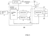
- FIG. 1 is a diagram showing an example of the configuration of the vehicle ignition device 100 according to the first embodiment.
- the vehicle ignition device 100 is loaded on a two-wheeled vehicle (not shown), and the control unit CNT is designed to control the operation of the engine (internal combustion engine) E of the two-wheeled vehicle.
- this vehicle ignition device 100 is loaded on a four-wheeled vehicle (not shown), and the control unit CNT may control the operation of the engine (internal combustion engine) E of the four-wheeled vehicle.
- this vehicle ignition device 100 includes a battery terminal TB, a primary side ignition coil L1, a secondary side ignition coil L2, a spark plug P, an injector E, a display unit A, a control switching element CSW, a detector C, a drive unit D, a main switch MSW, and a control unit CNT.
- control switching elements CSW, detector C, drive unit D, and control unit CNT constitute an ignition control unit (ignition control device) X.
- the battery terminal TB is supplied with an ignition voltage from the battery B, which is a DC power source.
- the primary side ignition coil L1 has one end that is connected to the battery terminal TB, and has the other end that is connected to the detection terminal TC.
- the secondary side ignition coil L2 has one end that is connected to the battery terminal TB, and has the other end that is connected to the plug terminal TP.
- This secondary side ignition coil L2 constitutes a transformer X together with the primary side ignition coil L1.
- the spark plug P has a first electrode (a center electrode) Plconnected to the plug terminal (a ground electrode) TP and a second electrode P2 connected to a fixed potential (a ground potential).
- the main switch MSW is connected between the positive electrode of the battery B and the battery terminal TB.
- the main switch MSW is controlled to be turned on / off by the user.
- the control unit CNT starts ignition control of the spark plug P by supplying electric power from the battery B.
- the control unit CNT stops the control operation by stopping the supply of electric power from the battery B.
- the display unit A is designed to display predetermined information to be provided to the user, by controlled by the control unit CNT.
- control unit CNT causes the display unit A to display the result of determining whether or not the spark plug P is normally ignited.
- control switching element CSW has one end that is connected to the detection terminal TC, and has the other end that is connected to the fixed potential (the ground potential).
- this control switching element CSW is an NPN type bipolar transistor (IGBT: including an insulated gate type bipolar transistor).
- the NPN type bipolar transistor has a collector that is connected to the detection terminal TC, and an emitter that is connected to the fixed potential (ground potential).
- the base current is controlled by the drive unit D.
- the detector C is adapted to detect the primary voltage of the detection terminal TC or the energizing current flowing from the detection terminal TC to the control switching element CSW.
- the drive unit D drives the control switching element CSW to control the control switching element CSW on or off, by controlling the base current supplied to the control switching element CSW.
- control unit CNT controls the control switching element CSW by the drive unit D, based on the value of the primary voltage detected by detector C and / or the value of the energizing current described above.
- This control unit CNT is configured to determine whether or not the spark plug P is normally ignited, based on a voltage comparison result comparing the value of the primary voltage detected by detector C with a preset threshold voltage, and/or a current comparison result comparing the value of the energizing current detected by detector C with the preset threshold current, in a preset detection period.
- control unit CNT is configured to stop the ignition of the spark plug P by turning off the control switching element CSW, for example, if the control unit CNT determines that the spark plug P is not igniting normally, based on the voltage comparison result and/or the current comparison result described above.
- the vehicle ignition device 100 is configured to stop ignition in the event of an abnormality.
- the values of the threshold voltage and/or the threshold current described above may be changed, depend on the energizing current or battery voltage value, by monitoring the energizing current or battery voltage at the same time. As a result, the accuracy of abnormality detection (the accuracy of the detection of ignition failure) can be improved.
- control unit CNT may determine that the spark plug P is not igniting normally, if the period during which the detected primary voltage exceeds the threshold voltage is equal to or longer than the preset reference time, in the detection period.
- control unit CNT may determine that the spark plug P is igniting normally, if the period during which the detected primary voltage exceeds the above-mentioned threshold voltage is less than the reference time in the detection period.
- control unit CNT may determine that the spark plug P is not igniting normally, if the detected primary voltage exceeds the preset first threshold voltage (for example, 400V) when the preset first standby time has elapsed after the ignition operation of the spark plug P is started.
- the preset first threshold voltage for example, 400V
- control unit CNT may determine that the spark plug P is igniting normally, if the detected primary voltage does not exceed the first threshold voltage when the first standby time has elapsed.
- control unit CNT may determine that the spark plug P is normally ignited, when the detected primary voltage exceeds the preset second threshold voltage (for example, 0V), at the timing when the preset second standby time longer than the first standby time elapses after the ignition operation of the spark plug P is started.
- the preset second threshold voltage for example, 0V
- control unit CNT may determine that the spark plug P is not igniting normally, if the detected primary voltage does not exceed the second threshold voltage, when the first waiting time has elapsed.
- control unit CNT may determine that the spark plug P is normally ignited, if the detected energizing current exceeds a preset threshold current, when the preset third standby time has elapsed after the ignition operation of the spark plug P is started.
- control unit CNT may determine that the spark plug P is not igniting normally, if the detected energizing current does not exceed the above-mentioned threshold current, when the third waiting time has elapsed.
- control unit CNT may acquire the battery voltage of the battery B and change the above-mentioned threshold voltage and/or the above-mentioned threshold current, based on the acquired battery voltage.
- the case where the spark plug P is not igniting normally (ignition failure) is, for example, a case where an open failure has occurred on the secondary side, a case where the gap width between the first electrode P1 and the second electrode P2 of the spark plug P is larger than the preset value, or a case where the foreign matter (the insulating material) is mixed in the gap between the first electrode P1 and the second electrode P2.
- this control unit CNT starts ignition control of the spark plug P by supplying electric power from the battery B.
- control unit CNT displays, the result of determining whether or not the spark plug P is normally ignited, on the display unit A.
- control unit CNT is designed to stop the operation of the injector F that injects fuel into the combustion chamber of the engine E, if the control unit CNT determines that the spark plug P is not igniting normally, based on the voltage comparison result and/or the current comparison result.
- the vehicle ignition device 100 can determine whether or not the spark is normally discharged, based on the voltage value (the current value) and application time during ignition operation on the primary side.
- FIG. 2 is a diagram showing an example of waveforms of the primary voltage of the detection terminal TC, the energizing current flowing through the detection terminal TC, and the secondary voltage of the plug terminal TP, when the energizing current is small, the gap width is normal, and the ignition is normal.
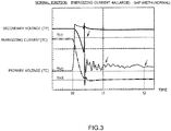
- FIG. 3 is a diagram showing an example of waveforms of the primary voltage of the detection terminal TC, the energizing current flowing through the detection terminal TC, and the secondary voltage of the plug terminal TP, when the energizing current is large, the gap width is normal, and the ignition is normal.
- FIG. 2 is a diagram showing an example of waveforms of the primary voltage of the detection terminal TC, the energizing current flowing through the detection terminal TC, and the secondary voltage of the plug terminal TP, when the energizing current is large, the gap width is normal, and the ignition is normal.
- FIG. 4 is a diagram showing an example of waveforms of the primary voltage of the detection terminal TC, the energizing current flowing through the detection terminal TC, and the secondary voltage of the plug terminal TP, when the energizing current is large, the gap width is large, and the ignition is normal.
- FIG. 5 is a diagram showing an example of waveforms of the primary voltage of the detection terminal TC, the energizing current flowing through the detection terminal TC, and the secondary voltage of the plug terminal TP, when the energizing current is small and the ignition is poor.
- FIG. 6 is a diagram showing an example of a waveform in which the time of FIG. 5 is lengthened.
- FIG. 7 is a diagram showing an example of waveforms of the primary voltage of the detection terminal TC, the energizing current flowing through the detection terminal TC, and the secondary voltage of the plug terminal TP, when the energizing current is large and the ignition is poor.
- the time t0 is the time when the control unit CNT starts the ignition operation by turning on the control switching element CSW by the drive unit D.
- the threshold voltage is the same value as the first threshold voltage TH1 for the sake of simplicity. However, the threshold voltage may be set to a value different from the first threshold voltage TH1.
- the case where the spark plug P is not ignited normally is, for example, a case where an open failure has occurred on the secondary side, a case where the gap width between the first electrode P1 and the second electrode P2 of the spark plug P is larger than a preset value, a case where foreign matter (insulating material) is mixed in the gap between the first electrode P1 and the second electrode P2, a case where the battery voltage of battery B is low, or a case where the primary side open chute failure has occurred.
- control unit CNT controls the control switching element CSW by the drive unit D, based on the value of the primary voltage detected by detector C and/or the value of the energizing current.
- This control unit CNT determines whether or not the spark plug P is normally ignited, based on A voltage comparison result comparing the value of the primary voltage detected by detector C with the preset threshold voltage, and/or the current comparison result comparing the value of the energizing current detected by detector C with the preset threshold current (not shown), in the preset detection period (for example, time t0 to time t1).
- control unit CNT acquires the battery voltage of the battery B and changes the above-mentioned threshold voltage and/or the above-mentioned threshold current, based on the acquired battery voltage.
- control unit CNT stops the ignition of the spark plug P by turning off the control switching element CSW, if the control unit CNT determines that the spark plug P is not igniting normally, for example, based on the voltage comparison result and / or the current comparison result described above.
- the vehicle ignition device 100 stops ignition when an abnormality occurs.
- this control unit CNT starts ignition control of the spark plug P by supplying electric power from the battery B.
- control unit CNT displays the result of judging whether or not the spark plug P is normally ignited, on the display unit A.
- control unit CNT stops the operation of the injector F that injects fuel into the combustion chamber of the engine E, if the control unit CNT determines that the spark plug is not igniting normally, based on the voltage comparison result and/or the current comparison result.
- control unit CNT determines that the spark plug P is not igniting normally ( Fig. 5 , Fig. 6 , and Fig. 7 ), if the period during which the detected primary voltage exceeds the threshold voltage is equal to or longer than the preset reference time, in the detection period (for example, time t0 to time t1).
- control unit CNT determines that the spark plug P is igniting normally ( Fig. 2 , Fig. 3 , and Fig. 4 ), if the period during which the detected primary voltage exceeds the above-mentioned threshold voltage is less than the reference time, in the detection period (for example, time t0 to time t1).
- control unit CNT determines that the spark plug P is not igniting normally ( Fig. 5 , Fig. 6 , and Fig. 7 ), if the detected primary voltage exceeds the preset first threshold voltage TH1 (for example, 400 V), when the preset first standby time (for example, 30 psec) elapses (for example, time t1) after the ignition operation of the spark plug P is started.
- the preset first threshold voltage TH1 for example, 400 V
- preset first standby time for example, 30 psec
- control unit CNT determines that the spark plug P is igniting normally ( Fig. 2 , Fig. 3 , and Fig. 4 ), if the detected primary voltage does not exceed the first threshold voltage, when the first waiting time has elapsed.
- the hardware configuration of the vehicle ignition device 100 can be facilitated, since it is possible to determine by voltage ("High” level / "Low” level) instead of determining by continuous time.
- control unit CNT may change the first standby time according to, for example, the value of the energizing current (or the battery voltage).
- control unit CNT determines that the spark plug P is igniting normally ( Fig. 2 , Fig. 3 , and Fig. 4 ), if the detected primary voltage exceeds the preset second threshold voltage (for example, 0V)TH2, when a preset second standby time (for example, 80 psec) longer than the first standby time has elapsed (for example, time t2) after the ignition operation of the spark plug P is started (the time t0).
- the preset second threshold voltage for example, 0V
- a preset second standby time for example, 80 psec
- control unit CNT determines that the spark plug P is not igniting normally ( Fig. 5 , Fig. 6 , and Fig. 7 ), if the detected primary voltage does not exceed the second threshold voltage when the first standby time has elapsed.
- the detected primary voltage is negative, it is determined that the spark plug P is not igniting normally.
- the current flows in the negative direction, thereby the detection is possible in this way.
- control unit CNT may change the second standby time according to, for example, the value of the energizing current (or the battery voltage).
- control unit CNT determines that the spark plug P is igniting normally ( FIG. 2 ), if the detected energizing current exceeds the preset threshold current (for example, 0A) THX (the detected energizing current is a positive current), when the preset third standby time (the time t3) elapses after the ignition operation of the spark plug P is started.
- the preset threshold current for example, 0A
- THX the preset third standby time
- control unit CNT determines that the spark plug P is not igniting normally ( Fig. 5 and Fig. 6 ), if the detected energizing current does not exceed the above-mentioned threshold current (the detected energizing current is a negative current) when the third standby time (the time t3) elapses.
- control unit CNT may change the third standby time according to, for example, the value of the energizing current (or the battery voltage).
- the vehicle ignition device 100 includes: a battery terminal TB to which an ignition voltage is supplied from a battery B; a primary side ignition coil L1 that has one end connected to the battery terminal TB, and has the other end connected to the detection terminal TC; a secondary side ignition coil L2 that has one end is connected to the battery terminal TB, and has the other end is connected to the plug terminal TP, the secondary side ignition coil L2 constituting a transformer together with the primary side ignition coil L1; a spark plug P that has a first electrode (a center electrode) P1 connected to the plug terminal, and has a second electrode (a ground electrode) P2 connected to a fixed potential (a ground potential); a control switching element CSW that has one end connected to the detection terminal TC, and has the other end connected to the fixed potential; a detector C that detects a primary voltage of the detection terminal TC or an energizing current flowing from the detection terminal to the control switching element CSW; a drive unit D that drives the control switching
- control unit CNT determines whether or not the spark plug P is normally ignited, based on the voltage comparison result comparing the value of the primary voltage detected by detector C with the preset threshold voltage, and/or the current comparison result comparing the value of the energizing current detected by detector C with the preset threshold current, in the preset detection period.
- the vehicle ignition device 100 it is possible to determine whether or not the spark is normally discharged, based on the voltage value (the current value) and application time during ignition operation on the primary side.
- control switching element CSW is an NPN type bipolar transistor
- FIG. 1 the example in which the control switching element CSW is an NPN type bipolar transistor has been described ( FIG. 1 ), but other semiconductor elements may be applied.
- control switching element CSW may be replaced with, for example, a PNP type bipolar transistor MOSFET (including IGBT: Insulated gate type bipolar transistor), or another semiconductor element so that the same function can be performed.
- a PNP type bipolar transistor MOSFET including IGBT: Insulated gate type bipolar transistor
- the ignition device includes: a battery terminal TB to which an ignition voltage is supplied from a battery B; a primary side ignition coil L1 that has one end connected to the battery terminal TB, and has the other end connected to the detection terminal TC; a secondary side ignition coil L2 that has one end is connected to the battery terminal TB, and has the other end is connected to the plug terminal TP, the secondary side ignition coil L2 constituting a transformer together with the primary side ignition coil L1; a spark plug P that has a first electrode (a center electrode) P1 connected to the plug terminal, and has a second electrode (a ground electrode) P2 connected to a fixed potential (a ground potential); a control switching element CSW that has one end connected to the detection terminal TC, and has the other end connected to the fixed potential; a detector C that detects a primary voltage of the detection terminal TC or an energizing current flowing from the detection terminal to the control switching element CSW; a drive unit D that drives the control switching element
- control unit CNT determines whether or not the spark plug P is normally ignited, based on the voltage comparison result comparing the value of the primary voltage detected by detector C with the preset threshold voltage, and/or the current comparison result comparing the value of the energizing current detected by detector C with the preset threshold current, in the preset detection period.
- the ignition device of the present invention it is possible to determine whether or not spark discharge is normal based on the voltage value (the current value) and application time during the ignition operation on the primary side.
Landscapes
- Engineering & Computer Science (AREA)
- Chemical & Material Sciences (AREA)
- Combustion & Propulsion (AREA)
- Mechanical Engineering (AREA)
- General Engineering & Computer Science (AREA)
- Ignition Installations For Internal Combustion Engines (AREA)
Abstract
Description
- The present invention relates to a vehicle ignition device, an ignition control device, and a control method of vehicle ignition device.
- For example, in a two-wheeled vehicle system, it is necessary to determine whether the spark plug of the ignition device is ignited and discharged by supporting OBD2 (On-board diagnostics 2).
- For example, it is possible to determine whether the ignition is discharged from the rotation fluctuation of the engine. In this case, it is possible to determine low rotation, but it is difficult to determine at high rotation because there is little fluctuation.
- On the other hand, in the four-wheeled vehicle system, since there is a margin of cost, the secondary side of the ignition device is directly detected (see, for example,
JP-A-2009-92035 JP-A-2015-20024 - Here, if the spark plug is not ignited and discharged normally, the switching element that controls ignition takes more energy than in the normal state. Therefore, the switching element may be damaged.
- And, when selecting an element that does not cause any problem even if a large amount of energy is applied so as not to break, it leads to an increase in the cost of the ignition device.
- Then, in the motorcycle system described above, when determining whether the spark discharge is normal in the igniter, the voltage is read by the detection circuit to determine whether the primary side of the ignition device is a normal connection, a disconnection, a ground fault, or a ceiling fault.
- The detection circuit used in such a conventional technique could not detect the state of the secondary side of the ignition device. In the detection circuit, there is a problem that even if it operates normally in terms of control, it is not known whether the spark is actually discharged.
- Therefore, an object of the present invention is to provide a vehicle ignition device capable of determining whether or not spark discharge is normal, based on the voltage value (current value) and application time during ignition operation on the primary side.
- A vehicle ignition device, according to an embodiment according to an aspect of the present invention, comprising:
- a battery terminal to which an ignition voltage is supplied from a battery;
- a primary side ignition coil that has one end connected to the battery terminal, and has the other end connected to the detection terminal;
- a secondary side ignition coil that has one end is connected to the battery terminal, and has the other end is connected to a plug terminal, the secondary side ignition coil constituting a transformer together with the primary side ignition coil;
- a spark plug that has a first electrode connected to the plug terminal, and has a second electrode connected to a fixed potential;
- a control switching element that has one end connected to the detection terminal, and has the other end connected to the fixed potential;
- a detector that detects a primary voltage of the detection terminal or an energizing current flowing from the detection terminal to the control switching element;
- a drive unit that drives the control switching element to control the control switching element on or off; and
- a control unit that controls the control switching element by the drive unit, based on a value of the primary voltage and/or a value of the energizing current detected by the detector,
- wherein the control unit determines whether or not the spark plug is normally ignited, based on a voltage comparison result comparing the value of the primary voltage detected by the detector with a preset threshold voltage and/or a current comparison result comparing the value of the energizing current detected by the detector with a preset threshold current, in a preset detection period.
- In the vehicle ignition device,
wherein the control unit turns off the control switching element and stops the ignition of the spark plug, if the control unit determines that the spark plug is not igniting normally, based on the voltage comparison result and/or the current comparison result. - In the vehicle ignition device,
wherein
the control unit determines that the spark plug is not igniting normally, when the period in which the detected primary voltage exceeds the threshold voltage is equal to or longer than a preset reference time, in the detection period,
on the other hand, the control unit determines that the spark plug is igniting normally, when the period in which the detected primary voltage exceeds the threshold voltage is less than the reference time, in the detection period. - In the vehicle ignition device,
wherein
the control unit determines that the spark plug is not igniting normally, if the detected primary voltage exceeds a preset first threshold voltage, when the preset first standby time elapses after the ignition operation of the spark plug is started,
on the other hand, the control unit determines that the spark plug is igniting normally, if the detected primary voltage does not exceed the first threshold voltage after the first standby time has elapsed. - In the vehicle ignition device,
wherein
the control unit determines that the spark plug is igniting normally, if the detected primary voltage exceeds a preset second threshold voltage, when a preset second standby time longer than the first standby time elapses after the ignition operation of the spark plug is started,
on the other hand, the control unit determines that the spark plug is not igniting normally, if the detected primary voltage does not exceed the second threshold voltage when the first standby time elapses. - In the vehicle ignition device,
wherein
the control unit determines that the spark plug is igniting normally, if the detected energization current exceeds the preset threshold current, when the preset third standby time elapses after the ignition operation of the spark plug is started,
on the other hand, the control unit determines that the spark plug is not igniting normally, if the detected energizing current does not exceed the threshold current, when the third waiting time has elapsed. - In the vehicle ignition device,
wherein the control unit acquires the battery voltage of the battery and changes the threshold voltage and/or the threshold current based on the acquired battery voltage. - In the vehicle ignition device,
wherein the case where the spark plug is not ignited normally is a case where an open failure has occurred on the secondary side, a case where the gap width between the first electrode and the second electrode of the spark plug is larger than a preset value, a case where foreign matter is mixed in the gap between the first electrode and the second electrode, a case where the battery voltage of the battery is low, or a case where the primary side open chute failure has occurred. - In the vehicle ignition device,
wherein the control switching element is a bipolar transistor that has a collector is connected to the detection terminal, and has an emitter is connected to the fixed potential, a base current of the bipolar transistor being controlled by the drive unit. - In the vehicle ignition device, further comprising a display unit that is controlled by the control unit, and displays predetermined information to be provided to a user,
wherein the control unit displays a result of determining whether or not the spark plug is normally ignited on the display unit. - In the vehicle ignition device,
wherein the vehicle ignition device is loaded on a motorcycle, and
wherein the control unit controls the operation of the engine of the motorcycle. - In the vehicle ignition device,
wherein the control unit stops an operation of an injector that injects fuel into a combustion chamber of the engine, if the control unit determines that the spark plug is not igniting normally, based on the voltage comparison result and/or the current comparison result. - In the vehicle ignition device, further comprising a main switch that is connected between the positive electrode of the battery and the battery terminal, the main switch is controlled on / off by a user,
wherein, when the main switch is turned on, the control unit starts ignition control of the spark plug. - An ignition control device, according to an embodiment according to an aspect of the present invention, applied to a vehicle ignition device that includes: a battery terminal to which an ignition voltage is supplied from a battery; a primary side ignition coil that has one end connected to the battery terminal, and has the other end connected to the detection terminal; a secondary side ignition coil that has one end is connected to the battery terminal, and has the other end is connected to a plug terminal, the secondary side ignition coil constituting a transformer together with the primary side ignition coil; and a spark plug that has a first electrode connected to the plug terminal, and has a second electrode connected to a fixed potential,
the ignition control device comprising: - a control switching element that has one end connected to the detection terminal, and has the other end connected to the fixed potential;
- a detector that detects a primary voltage of the detection terminal or an energizing current flowing from the detection terminal to the control switching element;
- a drive unit that drives the control switching element to control the control switching element on or off; and
- a control unit that controls the control switching element by the drive unit, based on a value of the primary voltage and/or a value of the energizing current detected by the detector,
- wherein the control unit determines whether or not the spark plug is normally ignited, based on a voltage comparison result comparing the value of the primary voltage detected by the detector with a preset threshold voltage and/or a current comparison result comparing the value of the energizing current detected by the detector with a preset threshold current, in a preset detection period.
- A control method of a vehicle ignition device, according to an embodiment according to an aspect of the present invention, the vehicle ignition device that includes: a battery terminal to which an ignition voltage is supplied from a battery; a primary side ignition coil that has one end connected to the battery terminal, and has the other end connected to the detection terminal; a secondary side ignition coil that has one end is connected to the battery terminal, and has the other end is connected to a plug terminal, the secondary side ignition coil constituting a transformer together with the primary side ignition coil; a spark plug that has a first electrode connected to the plug terminal, and has a second electrode connected to a fixed potential; a control switching element that has one end connected to the detection terminal, and has the other end connected to the fixed potential; a detector that detects a primary voltage of the detection terminal or an energizing current flowing from the detection terminal to the control switching element; a drive unit that drives the control switching element to control the control switching element on or off; a control unit that controls the control switching element by the drive unit, based on a value of the primary voltage and/or a value of the energizing current detected by the detector,
wherein the control unit determines whether or not the spark plug is normally ignited, based on a voltage comparison result comparing the value of the primary voltage detected by the detector with a preset threshold voltage and/or a current comparison result comparing the value of the energizing current detected by the detector with a preset threshold current, in a preset detection period. - As described above, the ignition device, according to one aspect of the present invention, includes: a battery terminal to which an ignition voltage is supplied from a battery; a primary side ignition coil that has one end connected to the battery terminal, and has the other end connected to the detection terminal; a secondary side ignition coil that has one end is connected to the battery terminal, and has the other end is connected to the plug terminal, the secondary side ignition coil constituting a transformer together with the primary side ignition coil; a spark plug that has a first electrode (a center electrode) P1 connected to the plug terminal, and has a second electrode (a ground electrode) connected to a fixed potential (a ground potential); a control switching element that has one end connected to the detection terminal, and has the other end connected to the fixed potential; a detector that detects a primary voltage of the detection terminal or an energizing current flowing from the detection terminal to the control switching element; a drive unit that drives the control switching element to control the control switching element on or off; and a control unit that controls the control switching element by the drive unit, based on a value of the primary voltage and/or a value of the energizing current detected by the detector.
- Then, the control unit determines whether or not the spark plug is normally ignited, based on the voltage comparison result comparing the value of the primary voltage detected by detector with the preset threshold voltage, and/or the current comparison result comparing the value of the energizing current detected by detector with the preset threshold current, in the preset detection period.
- That is, according to the ignition device of the present invention, it is possible to determine whether or not spark discharge is normal based on the voltage value (the current value) and application time during the ignition operation on the primary side.
-
- [
FIG. 1] FIG. 1 is a diagram showing an example of the configuration of thevehicle ignition device 100 according to the first embodiment. - [
FIG. 2] FIG. 2 is a diagram showing an example of waveforms of the primary voltage of the detection terminal TC, the energizing current flowing through the detection terminal TC, and the secondary voltage of the plug terminal TP, when the energizing current is small, the gap width is normal, and the ignition is normal. - [
FIG. 3] FIG. 3 is a diagram showing an example of waveforms of the primary voltage of the detection terminal TC, the energizing current flowing through the detection terminal TC, and the secondary voltage of the plug terminal TP, when the energizing current is large, the gap width is normal, and the ignition is normal. - [
FIG. 4] FIG. 4 is a diagram showing an example of waveforms of the primary voltage of the detection terminal TC, the energizing current flowing through the detection terminal TC, and the secondary voltage of the plug terminal TP, when the energizing current is large, the gap width is large, and the ignition is normal. - [
FIG. 5] FIG. 5 is a diagram showing an example of waveforms of the primary voltage of the detection terminal TC, the energizing current flowing through the detection terminal TC, and the secondary voltage of the plug terminal TP, when the energizing current is small and the ignition is poor. - [
FIG. 6] FIG. 6 is a diagram showing an example of a waveform in which the time ofFIG. 5 is lengthened. - [
FIG. 7] FIG. 7 is a diagram showing an example of waveforms of the primary voltage of the detection terminal TC, the energizing current flowing through the detection terminal TC, and the secondary voltage of the plug terminal TP, when the energizing current is large and the ignition is poor. - In the following, an embodiment of the present invention will be described with reference to the drawings.
-
FIG. 1 is a diagram showing an example of the configuration of thevehicle ignition device 100 according to the first embodiment. - The
vehicle ignition device 100 according to the first embodiment is loaded on a two-wheeled vehicle (not shown), and the control unit CNT is designed to control the operation of the engine (internal combustion engine) E of the two-wheeled vehicle. - Note that this
vehicle ignition device 100 is loaded on a four-wheeled vehicle (not shown), and the control unit CNT may control the operation of the engine (internal combustion engine) E of the four-wheeled vehicle. - For example, as shown in
FIG. 1 , thisvehicle ignition device 100 includes a battery terminal TB, a primary side ignition coil L1, a secondary side ignition coil L2, a spark plug P, an injector E, a display unit A, a control switching element CSW, a detector C, a drive unit D, a main switch MSW, and a control unit CNT. - Note that, for example, as shown in
FIG. 1 , the control switching elements CSW, detector C, drive unit D, and control unit CNT constitute an ignition control unit (ignition control device) X. - Then, as shown in
FIG. 1 , for example, the battery terminal TB is supplied with an ignition voltage from the battery B, which is a DC power source. - Furthermore, as shown in
FIG. 1 , the primary side ignition coil L1 has one end that is connected to the battery terminal TB, and has the other end that is connected to the detection terminal TC. - Furthermore, as shown in
FIG. 1 , for example, of the secondary side ignition coil L2 has one end that is connected to the battery terminal TB, and has the other end that is connected to the plug terminal TP. - This secondary side ignition coil L2 constitutes a transformer X together with the primary side ignition coil L1.
- Furthermore, for example, as shown in
FIG. 1 , the spark plug P has a first electrode (a center electrode) Plconnected to the plug terminal (a ground electrode) TP and a second electrode P2 connected to a fixed potential (a ground potential). - Furthermore, for example, as shown in
FIG. 1 , the main switch MSW is connected between the positive electrode of the battery B and the battery terminal TB. The main switch MSW is controlled to be turned on / off by the user. - For example, as described later, when this main switch MSW is turned on, the control unit CNT starts ignition control of the spark plug P by supplying electric power from the battery B. On the other hand, when the main switch MSW is turned off, the control unit CNT stops the control operation by stopping the supply of electric power from the battery B.
- In addition, the display unit A is designed to display predetermined information to be provided to the user, by controlled by the control unit CNT.
- As will be described later, the control unit CNT causes the display unit A to display the result of determining whether or not the spark plug P is normally ignited.
- Furthermore, as shown in
FIG. 1 , for example, the control switching element CSW has one end that is connected to the detection terminal TC, and has the other end that is connected to the fixed potential (the ground potential). - For example, as shown in
FIG. 1 , this control switching element CSW is an NPN type bipolar transistor (IGBT: including an insulated gate type bipolar transistor). The NPN type bipolar transistor has a collector that is connected to the detection terminal TC, and an emitter that is connected to the fixed potential (ground potential). In the NPN type bipolar transistor, the base current is controlled by the drive unit D. - Furthermore, as shown in
FIG. 1 , the detector C is adapted to detect the primary voltage of the detection terminal TC or the energizing current flowing from the detection terminal TC to the control switching element CSW. - Furthermore, the drive unit D drives the control switching element CSW to control the control switching element CSW on or off, by controlling the base current supplied to the control switching element CSW.
- Furthermore, the control unit CNT controls the control switching element CSW by the drive unit D, based on the value of the primary voltage detected by detector C and / or the value of the energizing current described above.
- This control unit CNT is configured to determine whether or not the spark plug P is normally ignited, based on a voltage comparison result comparing the value of the primary voltage detected by detector C with a preset threshold voltage, and/or a current comparison result comparing the value of the energizing current detected by detector C with the preset threshold current, in a preset detection period.
- Then, the control unit CNT is configured to stop the ignition of the spark plug P by turning off the control switching element CSW, for example, if the control unit CNT determines that the spark plug P is not igniting normally, based on the voltage comparison result and/or the current comparison result described above.
- In this way, the
vehicle ignition device 100 is configured to stop ignition in the event of an abnormality. - Note that, as will be described later, the values of the threshold voltage and/or the threshold current described above may be changed, depend on the energizing current or battery voltage value, by monitoring the energizing current or battery voltage at the same time. As a result, the accuracy of abnormality detection (the accuracy of the detection of ignition failure) can be improved.
- Here, for example, the control unit CNT may determine that the spark plug P is not igniting normally, if the period during which the detected primary voltage exceeds the threshold voltage is equal to or longer than the preset reference time, in the detection period.
- On the other hand, the control unit CNT may determine that the spark plug P is igniting normally, if the period during which the detected primary voltage exceeds the above-mentioned threshold voltage is less than the reference time in the detection period.
- Furthermore, for example, the control unit CNT may determine that the spark plug P is not igniting normally, if the detected primary voltage exceeds the preset first threshold voltage (for example, 400V) when the preset first standby time has elapsed after the ignition operation of the spark plug P is started.
- On the other hand, the control unit CNT may determine that the spark plug P is igniting normally, if the detected primary voltage does not exceed the first threshold voltage when the first standby time has elapsed.
- Furthermore, for example, the control unit CNT may determine that the spark plug P is normally ignited, when the detected primary voltage exceeds the preset second threshold voltage (for example, 0V), at the timing when the preset second standby time longer than the first standby time elapses after the ignition operation of the spark plug P is started.
- On the other hand, the control unit CNT may determine that the spark plug P is not igniting normally, if the detected primary voltage does not exceed the second threshold voltage, when the first waiting time has elapsed.
- Furthermore, for example, the control unit CNT may determine that the spark plug P is normally ignited, if the detected energizing current exceeds a preset threshold current, when the preset third standby time has elapsed after the ignition operation of the spark plug P is started.
- On the other hand, the control unit CNT may determine that the spark plug P is not igniting normally, if the detected energizing current does not exceed the above-mentioned threshold current, when the third waiting time has elapsed.
- Furthermore, the control unit CNT may acquire the battery voltage of the battery B and change the above-mentioned threshold voltage and/or the above-mentioned threshold current, based on the acquired battery voltage.
- The case where the spark plug P is not igniting normally (ignition failure) is, for example, a case where an open failure has occurred on the secondary side, a case where the gap width between the first electrode P1 and the second electrode P2 of the spark plug P is larger than the preset value, or a case where the foreign matter (the insulating material) is mixed in the gap between the first electrode P1 and the second electrode P2.
- As described above, when the main switch MSW is turned on, this control unit CNT starts ignition control of the spark plug P by supplying electric power from the battery B.
- Further, as described above, the control unit CNT displays, the result of determining whether or not the spark plug P is normally ignited, on the display unit A.
- Note that the control unit CNT is designed to stop the operation of the injector F that injects fuel into the combustion chamber of the engine E, if the control unit CNT determines that the spark plug P is not igniting normally, based on the voltage comparison result and/or the current comparison result.
- As described above, the
vehicle ignition device 100 according to the first embodiment can determine whether or not the spark is normally discharged, based on the voltage value (the current value) and application time during ignition operation on the primary side. - Next, an example of a control method for the
vehicle ignition device 100 having the above configuration will be described. Here,FIG. 2 is a diagram showing an example of waveforms of the primary voltage of the detection terminal TC, the energizing current flowing through the detection terminal TC, and the secondary voltage of the plug terminal TP, when the energizing current is small, the gap width is normal, and the ignition is normal.FIG. 3 is a diagram showing an example of waveforms of the primary voltage of the detection terminal TC, the energizing current flowing through the detection terminal TC, and the secondary voltage of the plug terminal TP, when the energizing current is large, the gap width is normal, and the ignition is normal.FIG. 4 is a diagram showing an example of waveforms of the primary voltage of the detection terminal TC, the energizing current flowing through the detection terminal TC, and the secondary voltage of the plug terminal TP, when the energizing current is large, the gap width is large, and the ignition is normal.FIG. 5 is a diagram showing an example of waveforms of the primary voltage of the detection terminal TC, the energizing current flowing through the detection terminal TC, and the secondary voltage of the plug terminal TP, when the energizing current is small and the ignition is poor.FIG. 6 is a diagram showing an example of a waveform in which the time ofFIG. 5 is lengthened.FIG. 7 is a diagram showing an example of waveforms of the primary voltage of the detection terminal TC, the energizing current flowing through the detection terminal TC, and the secondary voltage of the plug terminal TP, when the energizing current is large and the ignition is poor. - Note that, in
FIGS. 2 to 7 , the time t0 is the time when the control unit CNT starts the ignition operation by turning on the control switching element CSW by the drive unit D. - Furthermore, in
FIGS. 2 to 7 , the threshold voltage is the same value as the first threshold voltage TH1 for the sake of simplicity. However, the threshold voltage may be set to a value different from the first threshold voltage TH1. - As described above, the case where the spark plug P is not ignited normally (the ignition failure has occurred) is, for example, a case where an open failure has occurred on the secondary side, a case where the gap width between the first electrode P1 and the second electrode P2 of the spark plug P is larger than a preset value, a case where foreign matter (insulating material) is mixed in the gap between the first electrode P1 and the second electrode P2, a case where the battery voltage of battery B is low, or a case where the primary side open chute failure has occurred.
- As described above, the control unit CNT controls the control switching element CSW by the drive unit D, based on the value of the primary voltage detected by detector C and/or the value of the energizing current.
- This control unit CNT determines whether or not the spark plug P is normally ignited, based on A voltage comparison result comparing the value of the primary voltage detected by detector C with the preset threshold voltage, and/or the current comparison result comparing the value of the energizing current detected by detector C with the preset threshold current (not shown), in the preset detection period (for example, time t0 to time t1).
- Note that the control unit CNT acquires the battery voltage of the battery B and changes the above-mentioned threshold voltage and/or the above-mentioned threshold current, based on the acquired battery voltage.
- Then, the control unit CNT stops the ignition of the spark plug P by turning off the control switching element CSW, if the control unit CNT determines that the spark plug P is not igniting normally, for example, based on the voltage comparison result and / or the current comparison result described above.
- In this way, the
vehicle ignition device 100 stops ignition when an abnormality occurs. - As described above, when the main switch MSW is turned on, this control unit CNT starts ignition control of the spark plug P by supplying electric power from the battery B.
- Furthermore, as described above, the control unit CNT displays the result of judging whether or not the spark plug P is normally ignited, on the display unit A.
- Note that the control unit CNT stops the operation of the injector F that injects fuel into the combustion chamber of the engine E, if the control unit CNT determines that the spark plug is not igniting normally, based on the voltage comparison result and/or the current comparison result.
- Here, for example, the control unit CNT determines that the spark plug P is not igniting normally (
Fig. 5 ,Fig. 6 , andFig. 7 ), if the period during which the detected primary voltage exceeds the threshold voltage is equal to or longer than the preset reference time, in the detection period (for example, time t0 to time t1). - On the other hand, the control unit CNT determines that the spark plug P is igniting normally (
Fig. 2 ,Fig. 3 , andFig. 4 ), if the period during which the detected primary voltage exceeds the above-mentioned threshold voltage is less than the reference time, in the detection period (for example, time t0 to time t1). - Also, for example, the control unit CNT determines that the spark plug P is not igniting normally (
Fig. 5 ,Fig. 6 , andFig. 7 ), if the detected primary voltage exceeds the preset first threshold voltage TH1 (for example, 400 V), when the preset first standby time (for example, 30 psec) elapses (for example, time t1) after the ignition operation of the spark plug P is started. - On the other hand, the control unit CNT determines that the spark plug P is igniting normally (
Fig. 2 ,Fig. 3 , andFig. 4 ), if the detected primary voltage does not exceed the first threshold voltage, when the first waiting time has elapsed. - . In this case, the hardware configuration of the
vehicle ignition device 100 can be facilitated, since it is possible to determine by voltage ("High" level / "Low" level) instead of determining by continuous time. - Note that the control unit CNT may change the first standby time according to, for example, the value of the energizing current (or the battery voltage).
- Also, for example, the control unit CNT determines that the spark plug P is igniting normally (
Fig. 2 ,Fig. 3 , andFig. 4 ), if the detected primary voltage exceeds the preset second threshold voltage (for example, 0V)TH2, when a preset second standby time (for example, 80 psec) longer than the first standby time has elapsed (for example, time t2) after the ignition operation of the spark plug P is started (the time t0). - On the other hand, the control unit CNT determines that the spark plug P is not igniting normally (
Fig. 5 ,Fig. 6 , andFig. 7 ), if the detected primary voltage does not exceed the second threshold voltage when the first standby time has elapsed. - In this case, if the detected primary voltage is negative, it is determined that the spark plug P is not igniting normally. When ignition is defective, the current flows in the negative direction, thereby the detection is possible in this way.
- Note that the control unit CNT may change the second standby time according to, for example, the value of the energizing current (or the battery voltage).
- Also, for example, the control unit CNT determines that the spark plug P is igniting normally (
FIG. 2 ), if the detected energizing current exceeds the preset threshold current (for example, 0A) THX (the detected energizing current is a positive current), when the preset third standby time (the time t3) elapses after the ignition operation of the spark plug P is started. - On the other hand, the control unit CNT determines that the spark plug P is not igniting normally (
Fig. 5 andFig. 6 ), if the detected energizing current does not exceed the above-mentioned threshold current (the detected energizing current is a negative current) when the third standby time (the time t3) elapses. - In this way, by checking the energizing current after ignition, when ignition is defective, current flows in the negative direction, so it can be detected.
- Note that the control unit CNT may change the third standby time according to, for example, the value of the energizing current (or the battery voltage).
- As described above, as shown in
Fig. 1 , the vehicle ignition device 100 includes: a battery terminal TB to which an ignition voltage is supplied from a battery B; a primary side ignition coil L1 that has one end connected to the battery terminal TB, and has the other end connected to the detection terminal TC; a secondary side ignition coil L2 that has one end is connected to the battery terminal TB, and has the other end is connected to the plug terminal TP, the secondary side ignition coil L2 constituting a transformer together with the primary side ignition coil L1; a spark plug P that has a first electrode (a center electrode) P1 connected to the plug terminal, and has a second electrode (a ground electrode) P2 connected to a fixed potential (a ground potential); a control switching element CSW that has one end connected to the detection terminal TC, and has the other end connected to the fixed potential; a detector C that detects a primary voltage of the detection terminal TC or an energizing current flowing from the detection terminal to the control switching element CSW; a drive unit D that drives the control switching element to control the control switching element on or off; and a control unit CNT that controls the control switching element CSW by the drive unit D, based on a value of the primary voltage and/or a value of the energizing current detected by the detector C. - Then, the control unit CNT determines whether or not the spark plug P is normally ignited, based on the voltage comparison result comparing the value of the primary voltage detected by detector C with the preset threshold voltage, and/or the current comparison result comparing the value of the energizing current detected by detector C with the preset threshold current, in the preset detection period.
- That is, according to the
vehicle ignition device 100 according to the first embodiment, it is possible to determine whether or not the spark is normally discharged, based on the voltage value (the current value) and application time during ignition operation on the primary side. - In the above-described first embodiment, the example in which the control switching element CSW is an NPN type bipolar transistor has been described (
FIG. 1 ), but other semiconductor elements may be applied. - That is, the control switching element CSW may be replaced with, for example, a PNP type bipolar transistor MOSFET (including IGBT: Insulated gate type bipolar transistor), or another semiconductor element so that the same function can be performed.
- Note that the configuration of the other vehicle ignition device in the second embodiment is the same as that in the first embodiment.
- As described above, the ignition device, according to one aspect of the present invention, includes: a battery terminal TB to which an ignition voltage is supplied from a battery B; a primary side ignition coil L1 that has one end connected to the battery terminal TB, and has the other end connected to the detection terminal TC; a secondary side ignition coil L2 that has one end is connected to the battery terminal TB, and has the other end is connected to the plug terminal TP, the secondary side ignition coil L2 constituting a transformer together with the primary side ignition coil L1; a spark plug P that has a first electrode (a center electrode) P1 connected to the plug terminal, and has a second electrode (a ground electrode) P2 connected to a fixed potential (a ground potential); a control switching element CSW that has one end connected to the detection terminal TC, and has the other end connected to the fixed potential; a detector C that detects a primary voltage of the detection terminal TC or an energizing current flowing from the detection terminal to the control switching element CSW; a drive unit D that drives the control switching element to control the control switching element on or off; and a control unit CNT that controls the control switching element CSW by the drive unit D, based on a value of the primary voltage and/or a value of the energizing current detected by the detector C.
- Then, the control unit CNT determines whether or not the spark plug P is normally ignited, based on the voltage comparison result comparing the value of the primary voltage detected by detector C with the preset threshold voltage, and/or the current comparison result comparing the value of the energizing current detected by detector C with the preset threshold current, in the preset detection period.
- That is, according to the ignition device of the present invention, it is possible to determine whether or not spark discharge is normal based on the voltage value (the current value) and application time during the ignition operation on the primary side.
- While certain embodiments have been described, these embodiments have been presented by way of example only, and are not intended to limit the scope of the inventions. The embodiments may be embodied in a variety of other forms. Furthermore, various omissions, substitutions and changes in the form of the methods and systems described herein may be made without departing from the spirit of the inventions. The embodiments and their modifications are included in the scope and the subject matter of the invention, and at the same time included in the scope of the claimed inventions and their equivalents.
-
- 100 vehicle ignition device
- TB battery terminal
- L1 primary side ignition coil
- L2 secondary side ignition coil
- P spark plug
- A display unit
- CSW control switching element
- C detector
- D drive unit
- MSW main switch
- CNT control unit
- E engine
- F injector
- TP plug terminal
- P1 first electrode (center electrode)
- P2 second electrode (ground electrode)
- X transformer
- B battery
Claims (15)
- A vehicle ignition device, comprising:a battery terminal to which an ignition voltage is supplied from a battery;a primary side ignition coil that has one end connected to the battery terminal, and has the other end connected to the detection terminal;a secondary side ignition coil that has one end is connected to the battery terminal, and has the other end is connected to a plug terminal, the secondary side ignition coil constituting a transformer together with the primary side ignition coil;a spark plug that has a first electrode connected to the plug terminal, and has a second electrode connected to a fixed potential;a control switching element that has one end connected to the detection terminal, and has the other end connected to the fixed potential;a detector that detects a primary voltage of the detection terminal or an energizing current flowing from the detection terminal to the control switching element;a drive unit that drives the control switching element to control the control switching element on or off; anda control unit that controls the control switching element by the drive unit, based on a value of the primary voltage and/or a value of the energizing current detected by the detector,wherein the control unit determines whether or not the spark plug is normally ignited, based on a voltage comparison result comparing the value of the primary voltage detected by the detector with a preset threshold voltage and/or a current comparison result comparing the value of the energizing current detected by the detector with a preset threshold current, in a preset detection period.
- The vehicle ignition device according to claim 1,
wherein the control unit turns off the control switching element and stops the ignition of the spark plug, if the control unit determines that the spark plug is not igniting normally, based on the voltage comparison result and/or the current comparison result. - The vehicle ignition device according to claim 2,
wherein
the control unit determines that the spark plug is not igniting normally, when the period in which the detected primary voltage exceeds the threshold voltage is equal to or longer than a preset reference time, in the detection period,
on the other hand, the control unit determines that the spark plug is igniting normally, when the period in which the detected primary voltage exceeds the threshold voltage is less than the reference time, in the detection period. - The vehicle ignition device according to claim 2,
wherein
the control unit determines that the spark plug is not igniting normally, if the detected primary voltage exceeds a preset first threshold voltage, when the preset first standby time elapses after the ignition operation of the spark plug is started,
on the other hand, the control unit determines that the spark plug is igniting normally, if the detected primary voltage does not exceed the first threshold voltage after the first standby time has elapsed. - The vehicle ignition device according to claim 2,
wherein
the control unit determines that the spark plug is igniting normally, if the detected primary voltage exceeds a preset second threshold voltage, when a preset second standby time longer than the first standby time elapses after the ignition operation of the spark plug is started,
on the other hand, the control unit determines that the spark plug is not igniting normally, if the detected primary voltage does not exceed the second threshold voltage when the first standby time has elapsed. - The vehicle ignition device according to claim 2,
wherein
the control unit determines that the spark plug is igniting normally, if the detected energization current exceeds the preset threshold current, when the preset third standby time elapses after the ignition operation of the spark plug is started,
on the other hand, the control unit determines that the spark plug is not igniting normally, if the detected energizing current does not exceed the threshold current, when the third waiting time has elapsed. - The vehicle ignition device according to claim 2,
wherein the control unit acquires the battery voltage of the battery and changes the threshold voltage and/or the threshold current based on the acquired battery voltage. - The vehicle ignition device according to claim 2,
wherein the case where the spark plug is not ignited normally is a case where an open failure has occurred on the secondary side, a case where the gap width between the first electrode and the second electrode of the spark plug is larger than a preset value, a case where foreign matter is mixed in the gap between the first electrode and the second electrode, a case where the battery voltage of the battery is low, or a case where the primary side open chute failure has occurred. - The vehicle ignition device according to claim 2,
wherein the control switching element is a bipolar transistor that has a collector is connected to the detection terminal, and has an emitter is connected to the fixed potential, a base current of the bipolar transistor being controlled by the drive unit. - The vehicle ignition device according to claim 2, further comprising a display unit that is controlled by the control unit, and displays predetermined information to be provided to a user,
wherein the control unit displays a result of determining whether or not the spark plug is normally ignited on the display unit. - The vehicle ignition device according to claim 2,
wherein the vehicle ignition device is loaded on a motorcycle, and wherein the control unit controls the operation of the engine of the motorcycle. - The vehicle ignition device according to claim 11,
wherein the control unit stops an operation of an injector that injects fuel into a combustion chamber of the engine, if the control unit determines that the spark plug is not igniting normally, based on the voltage comparison result and/or the current comparison result. - The vehicle ignition device according to claim 2, further comprising a main switch that is connected between the positive electrode of the battery and the battery terminal, the main switch is controlled on / off by a user,
wherein, when the main switch is turned on, the control unit starts ignition control of the spark plug. - An ignition control device applied to a vehicle ignition device that includes: a battery terminal to which an ignition voltage is supplied from a battery; a primary side ignition coil that has one end connected to the battery terminal, and has the other end connected to the detection terminal; a secondary side ignition coil that has one end is connected to the battery terminal, and has the other end is connected to a plug terminal, the secondary side ignition coil constituting a transformer together with the primary side ignition coil; and a spark plug that has a first electrode connected to the plug terminal, and has a second electrode connected to a fixed potential,
the ignition control device comprising:a control switching element that has one end connected to the detection terminal, and has the other end connected to the fixed potential;a detector that detects a primary voltage of the detection terminal or an energizing current flowing from the detection terminal to the control switching element;a drive unit that drives the control switching element to control the control switching element on or off; anda control unit that controls the control switching element by the drive unit, based on a value of the primary voltage and/or a value of the energizing current detected by the detector,wherein the control unit determines whether or not the spark plug is normally ignited, based on a voltage comparison result comparing the value of the primary voltage detected by the detector with a preset threshold voltage and/or a current comparison result comparing the value of the energizing current detected by the detector with a preset threshold current, in a preset detection period. - A control method of a vehicle ignition device that includes: a battery terminal to which an ignition voltage is supplied from a battery; a primary side ignition coil that has one end connected to the battery terminal, and has the other end connected to the detection terminal; a secondary side ignition coil that has one end is connected to the battery terminal, and has the other end is connected to a plug terminal, the secondary side ignition coil constituting a transformer together with the primary side ignition coil; a spark plug that has a first electrode connected to the plug terminal, and has a second electrode connected to a fixed potential; a control switching element that has one end connected to the detection terminal, and has the other end connected to the fixed potential; a detector that detects a primary voltage of the detection terminal or an energizing current flowing from the detection terminal to the control switching element; a drive unit that drives the control switching element to control the control switching element on or off; a control unit that controls the control switching element by the drive unit, based on a value of the primary voltage and/or a value of the energizing current detected by the detector,
wherein the control unit determines whether or not the spark plug is normally ignited, based on a voltage comparison result comparing the value of the primary voltage detected by the detector with a preset threshold voltage and/or a current comparison result comparing the value of the energizing current detected by the detector with a preset threshold current, in a preset detection period.
Applications Claiming Priority (1)
| Application Number | Priority Date | Filing Date | Title |
|---|---|---|---|
| PCT/JP2018/033123 WO2020049704A1 (en) | 2018-09-07 | 2018-09-07 | Vehicle ignition device, ignition control device, and control method of vehicle ignition device |
Publications (2)
| Publication Number | Publication Date |
|---|---|
| EP3848571A1 true EP3848571A1 (en) | 2021-07-14 |
| EP3848571A4 EP3848571A4 (en) | 2021-09-22 |
Family
ID=69722798
Family Applications (1)
| Application Number | Title | Priority Date | Filing Date |
|---|---|---|---|
| EP18932617.6A Pending EP3848571A4 (en) | 2018-09-07 | 2018-09-07 | VEHICLE IGNITION DEVICE, IGNITION CONTROL DEVICE AND CONTROL METHOD OF A VEHICLE IGNITION DEVICE |
Country Status (3)
| Country | Link |
|---|---|
| EP (1) | EP3848571A4 (en) |
| JP (1) | JP6984028B2 (en) |
| WO (1) | WO2020049704A1 (en) |
Family Cites Families (10)
| Publication number | Priority date | Publication date | Assignee | Title |
|---|---|---|---|---|
| JP2665794B2 (en) * | 1989-03-13 | 1997-10-22 | 愛三工業株式会社 | Ignition device for internal combustion engine |
| JPH02126077U (en) * | 1989-03-27 | 1990-10-17 | ||
| US5283527A (en) * | 1991-06-28 | 1994-02-01 | Ford Motor Company | Methods and apparatus for detecting short circuited secondary coil winding via monitoring primary coil winding |
| JPH09100772A (en) * | 1995-10-04 | 1997-04-15 | Denso Corp | Misfire detection device for internal combustion engine |
| EP1222385A1 (en) * | 1999-10-06 | 2002-07-17 | Robert Bosch Gmbh | Device and method for ignition in an internal combustion engine |
| JP2005042643A (en) * | 2003-07-24 | 2005-02-17 | Kokusan Denki Co Ltd | Ignitor for internal combustion engines |
| JP2007162619A (en) * | 2005-12-15 | 2007-06-28 | Toyota Motor Corp | Ignition control device for internal combustion engine |
| JP4420951B2 (en) | 2007-10-11 | 2010-02-24 | 三菱電機株式会社 | Ignition diagnosis device for internal combustion engine and control device for internal combustion engine |
| JP5913217B2 (en) | 2013-07-23 | 2016-04-27 | 京楽産業.株式会社 | Game machine |
| JP6696334B2 (en) * | 2016-07-11 | 2020-05-20 | 株式会社デンソー | Ignition device |
-
2018
- 2018-09-07 EP EP18932617.6A patent/EP3848571A4/en active Pending
- 2018-09-07 JP JP2020540960A patent/JP6984028B2/en active Active
- 2018-09-07 WO PCT/JP2018/033123 patent/WO2020049704A1/en not_active Ceased
Also Published As
| Publication number | Publication date |
|---|---|
| EP3848571A4 (en) | 2021-09-22 |
| JPWO2020049704A1 (en) | 2021-08-12 |
| WO2020049704A1 (en) | 2020-03-12 |
| JP6984028B2 (en) | 2021-12-17 |
Similar Documents
| Publication | Publication Date | Title |
|---|---|---|
| US9726140B2 (en) | Internal combustion engine control apparatus | |
| US7467626B2 (en) | Ignition device of ignition control system for an internal combustion engine | |
| US7764021B2 (en) | Integrated circuit capable of enhanced lamp ignition | |
| US10422310B2 (en) | Ignition device | |
| US8860419B2 (en) | Ion current detector | |
| JP2008031981A (en) | Abnormality detection device for internal combustion engine | |
| JP2009174348A (en) | Internal combustion engine ignition device | |
| JP4188290B2 (en) | Internal combustion engine ignition device | |
| JP2015200250A (en) | Ignition device | |
| JP2009221850A (en) | Igniter with ion current detection function | |
| JPWO2019198119A1 (en) | Ignition system for internal combustion engine | |
| JP6984028B2 (en) | Vehicle ignition device, ignition control device, and control method for vehicle ignition device | |
| US11417459B2 (en) | Ignition system | |
| JPWO2019130462A1 (en) | Ignition system for internal combustion engine | |
| US20220275783A1 (en) | Electronic device and control system of an ignition coil in an internal combustion engine | |
| JP2848470B2 (en) | Failure detection device for ignition device for internal combustion engine | |
| JP2015025403A (en) | Ignition device for internal combustion engine, ignition control device used for the same, and discharge unit | |
| JP2007309098A (en) | Ignition coil for internal combustion engine | |
| JP2010106702A (en) | Combustion state detector for internal combustion engine | |
| JPH0774630B2 (en) | Internal combustion engine ignition device | |
| JP2021156171A (en) | Ignition device for internal combustion engine | |
| TW202605238A (en) | Vehicle ignition control system and method which is an ignition control system using cutoff circuit to limit voltage and prevent engine reverse rotation | |
| US20220120251A1 (en) | Electronic device to control an ignition coil of an internal combustion engine and electronic ignition system thereof for detecting a misfire in the internal combustion engine | |
| US20220136477A1 (en) | Electronic device to control an ignition coil of an internal combustion engine and electronic ignition system thereof for detecting a pre-ignition in the internal combustion engine | |
| JPH1018952A (en) | Ignition system for internal combustion engine |
Legal Events
| Date | Code | Title | Description |
|---|---|---|---|
| STAA | Information on the status of an ep patent application or granted ep patent |
Free format text: STATUS: THE INTERNATIONAL PUBLICATION HAS BEEN MADE |
|
| PUAI | Public reference made under article 153(3) epc to a published international application that has entered the european phase |
Free format text: ORIGINAL CODE: 0009012 |
|
| STAA | Information on the status of an ep patent application or granted ep patent |
Free format text: STATUS: REQUEST FOR EXAMINATION WAS MADE |
|
| 17P | Request for examination filed |
Effective date: 20210226 |
|
| AK | Designated contracting states |
Kind code of ref document: A1 Designated state(s): AL AT BE BG CH CY CZ DE DK EE ES FI FR GB GR HR HU IE IS IT LI LT LU LV MC MK MT NL NO PL PT RO RS SE SI SK SM TR |
|
| A4 | Supplementary search report drawn up and despatched |
Effective date: 20210819 |
|
| RIC1 | Information provided on ipc code assigned before grant |
Ipc: F02P 3/02 20060101ALN20210813BHEP Ipc: F02P 17/12 20060101AFI20210813BHEP |
|
| DAV | Request for validation of the european patent (deleted) | ||
| DAX | Request for extension of the european patent (deleted) | ||
| STAA | Information on the status of an ep patent application or granted ep patent |
Free format text: STATUS: EXAMINATION IS IN PROGRESS |
|
| 17Q | First examination report despatched |
Effective date: 20230328 |