EP3848538A1 - Clip for attaching a mesh panel in a fence with fence posts and a fence equipped therewith - Google Patents
Clip for attaching a mesh panel in a fence with fence posts and a fence equipped therewith Download PDFInfo
- Publication number
- EP3848538A1 EP3848538A1 EP21150294.3A EP21150294A EP3848538A1 EP 3848538 A1 EP3848538 A1 EP 3848538A1 EP 21150294 A EP21150294 A EP 21150294A EP 3848538 A1 EP3848538 A1 EP 3848538A1
- Authority
- EP
- European Patent Office
- Prior art keywords
- groove
- fence
- panel
- clip
- grooves
- Prior art date
- Legal status (The legal status is an assumption and is not a legal conclusion. Google has not performed a legal analysis and makes no representation as to the accuracy of the status listed.)
- Granted
Links
Images


Classifications
-
- E—FIXED CONSTRUCTIONS
- E04—BUILDING
- E04H—BUILDINGS OR LIKE STRUCTURES FOR PARTICULAR PURPOSES; SWIMMING OR SPLASH BATHS OR POOLS; MASTS; FENCING; TENTS OR CANOPIES, IN GENERAL
- E04H17/00—Fencing, e.g. fences, enclosures, corrals
- E04H17/14—Fences constructed of rigid elements, e.g. with additional wire fillings or with posts
- E04H17/16—Fences constructed of rigid elements, e.g. with additional wire fillings or with posts using prefabricated panel-like elements, e.g. wired frames
- E04H17/168—Fences constructed of rigid elements, e.g. with additional wire fillings or with posts using prefabricated panel-like elements, e.g. wired frames using panels fitted in grooves of posts
-
- E—FIXED CONSTRUCTIONS
- E04—BUILDING
- E04H—BUILDINGS OR LIKE STRUCTURES FOR PARTICULAR PURPOSES; SWIMMING OR SPLASH BATHS OR POOLS; MASTS; FENCING; TENTS OR CANOPIES, IN GENERAL
- E04H17/00—Fencing, e.g. fences, enclosures, corrals
- E04H17/14—Fences constructed of rigid elements, e.g. with additional wire fillings or with posts
- E04H17/16—Fences constructed of rigid elements, e.g. with additional wire fillings or with posts using prefabricated panel-like elements, e.g. wired frames
- E04H17/161—Fences constructed of rigid elements, e.g. with additional wire fillings or with posts using prefabricated panel-like elements, e.g. wired frames using wire panels
-
- E—FIXED CONSTRUCTIONS
- E04—BUILDING
- E04H—BUILDINGS OR LIKE STRUCTURES FOR PARTICULAR PURPOSES; SWIMMING OR SPLASH BATHS OR POOLS; MASTS; FENCING; TENTS OR CANOPIES, IN GENERAL
- E04H17/00—Fencing, e.g. fences, enclosures, corrals
- E04H17/14—Fences constructed of rigid elements, e.g. with additional wire fillings or with posts
- E04H17/20—Posts therefor
- E04H17/21—Posts therefor with hollow cross sections
Definitions
- the present invention relates to a clip for attaching a mesh panel in a fence with fence posts.
- a fence is constructed from vertical fence posts which are secured in the ground and are provided with an H-shaped section with grooves on either side of the fence post and panels which are mounted between the fence posts and with their side edges are enclosed in said grooves of the fence posts.
- the invention is particularly intended for panels of the type composed of wires or rods which are mutually connected in a grid of horizontal and vertical wires.
- 2D panels are found which are essentially flat because the vertical wires are straight and located in a same plane and 3D panels which are not flat but have a certain thickness and a sort of open wave structure as it were with protruding pointed kinked projections to one side.
- a disadvantage is that for attaching said different types of panels no universal method or clip exists.
- a clip is known from EP3.521.536 for mounting mesh panels in a fence post with a U-shaped groove on either side, whereby the clip is provided with notches which are hooked over a vertical wire of the panel and with which the panel is secured on the fence post with the vertical wire in a notch being clamped between the clip and the bottom of the groove.
- the clip is provided with vertical clip parts with which the clip is hooked into the holes in the legs of the U-shaped groove.
- a system is known from FR2.908.440 with fence posts with legs that delimit a groove and clips for attaching a mesh panel between the clips and the bottom of the groove.
- the system can only be used with fence posts with a complex form, the legs of which are provided with inwardly oriented protrusions behind which the clips can be hooked.
- the purpose of the present invention is to provide a solution to one or more of the aforementioned and other disadvantages.
- the invention relates to a clip for attaching a panel in a fence, particularly a mesh panel with vertical and horizontal wires, whereby the panel is mounted between vertical fence posts in the form of a profile with grooves delimited by parallel legs of the profile and whereby the panel is attached in the grooves of the profile with its side edges, characterised in that the clip contains a support platelet with a width delimited between two side edges and a supporting edge to rest against the bottom of the groove, said support platelet being intended to be attached horizontally in said groove of the fence post to support a horizontal wire of the panel and containing at least one groove for a vertical wire to said side edge of the panel, whereby said groove is essentially perpendicular to said supporting edge and thus parallel with the legs of the groove, whereby said groove is connected with an edge of the support platelet via an entry for the vertical wire and via a connecting groove which is at least in part parallel or at an angle with the supporting edge.
- the panel can be hooked via the entry of the support platelet in said groove or in one of said grooves in such a way that the panel with a horizontal wire, preferably the upper horizontal wire, can rest on the support platelet.
- a horizontal wire preferably the upper horizontal wire
- the support platelet is a rectangular platelet having a width E, which, apart from a lateral clearance S, is essentially equal to the width F of the groove and a length which is practically equal to the depth of the groove and said entry is machined in a corner of the support platelet on the opposite edge of said supporting edge.
- the support platelet can move little in the groove and the entry of the support platelet is easily accessible at the entry of the groove.
- the grooves are connected with the entry of the support platelet via a connecting groove essentially parallel with the supporting edge of the attachment platelet, such that the panel with its vertical wire on a side edge is hooked by a perpendicular motion in a groove of the support platelet.
- the attachment platelet contains at least a central groove in the middle between the two side edges of the support platelet.
- Said groove can for example serve for attaching a 2D panel in the middle between the legs of the groove.
- the attachment platelet contains at least two grooves at a lateral distance from each other and said grooves are connected with the entry via said connecting groove, whereby said grooves are each preferably located at the same lateral distance from an adjacent side edge of the support platelet.
- Said grooves are intended for mounting a 3D panel, whereby one such groove is intended for mounting the 3D panel with its protruding pointed projections oriented toward one side of the fence and the other groove is intended for mounting with the protrusions oriented toward the other side of the fence.
- the clip is universal for all commonly used 2D- and 3D panels.
- said entry tapers off conically from the contour of the support platelet onwards and ends in the connecting groove.
- the smallest width G of the entry measured relative to a side edge of the support platelet, is such that in mounted condition of the support platelet with a lateral clearance S in a groove (7), said smallest width G increased with said clearance S is smaller than the sum of the diameters of a vertical wire and a horizontal wire of the panel.
- a panel can only be hooked in the attachment platelet when lifting the panel with its upper horizontal wire over a certain distance above the attachment platelet while holding its side edge in a slightly slanted position relative to the fence post.
- the panels can no longer be removed as the panels can no longer be tilted in a slanted position and can also only be lifted to a limited extent, thereby hindered by the horizontal wires just under the upper wires.
- the clips also provide security against theft of the panels.
- the invention also relates to a fence that is composed of fence posts in the form of a profile with grooves and of panels which are attached between the fence posts by means of clips as described above.
- the fence posts are formed as a hollow H-profile that is folded in one piece from a metal sheet or band, whereby the bottom of the groove is formed by a transverse wall and the clip is provided with a hook-shaped part with which the clip can be fittingly hooked over the transverse wall.
- the mounting of the panels between the fence posts does not require a single tool in this case, not for mounting the clips, nor for mounting the panels in the clips.
- the fence posts can be protected at the top by caps with a clamping section that is firmly clamped in the hollow fence post to make removal of the clips without damaging the fence difficult.
- the fence 1 shown in figure 1 is constructed from vertical fence posts 2 which are driven in the ground 3 for example and between which panels 4 are attached.
- the panels 4 are mesh panels which are composed of wires 5 or rods attached to each other, respectively straight rigid wires 5a which at different heights are always enclosed between two horizontal rigid straight wires 5 at a vertical distance A from each other.
- 2D panels which exist in different sizes and which are typified by the diameters of the wires 5.
- 2D panels 8/6/8 exist, referring to two horizontal wires 5b of 8 mm, with a vertical wire 5a of 6mm in between.
- 2D panels 6/5/6 also exist.
- the fence posts 2 are made in the form of an H-profile 6 with two opposite grooves 7 on either side of the fence post 2 where a panel 4 with a wire 5a fits and is attached in the side edge 8 of the panel 4, for example by means of a clip 9 as shown in figure 4 .
- the fence posts 2 are made of one single metal sheet or band 10 of which a strip with limited length A is shown in figure 3 and which breadthways B is folded between two side edges 11 along folding lines 12, respectively folding lines 12a and 12b, which extend parallel to the side edges 11 to form the H-profile 6 as shown in figure 2 with a tubular square central part 13 and legs 14 which delimit the grooves 7 and lie in each other's extension in pairs.
- the folding lines 12 delimit a number of vertical bands which correspond with folding sections of the H-profile 6, respectively bands and folding sections 15, 16, 17, 18 and 19 with corresponding widths B15, B16, B17, B18 and B19.
- the sheet or band 10 On the level of the folding lines 12a, the sheet or band 10 is folded over in a straight angle to form the corners of the tubular square central part 13, whereas on the level of the folding lines 12b the sheet or band 10 is folded over double over 180° until the plate parts touch on either side of the folding line 12b to form the legs 14 with the folding lines 12b on the level of the free ends of the legs 14.
- the sheet or band 10 is folded such that the side edges 11 touch or practically touch, such that said side edges 11 of the bands 15 can be connected with each other by a welded joint 20.
- the bands 17 form flat parallel flanks 21 of the H-profile 6, whereas the welded together bands 15 and the band 19 form the transversal walls 22 between the flanks 17.
- the panels 4 are attached in the grooves 7 with their side edges 8, as shown in figure 4 , by means of clips 9, as shown in the figures 4 to 6 .
- the clips 9 are formed from die cut platelets 23 for example as shown in figure 7 with a narrowed lip-shaped part 24 which is folded over along a folding zone 25 to form a U-shaped hook-shaped folded over part 25 with which the clip 9 can be fittingly hooked over a transverse wall 22 of the fence post 2 as shown in the figures 4 to 6 and if necessary can be attached to it by means of a screw, rivet or the like.
- the platelet 23 is folded over at right angles along a folding line 27 to form a rectangular support platelet 28 extending toward the groove 7 with a width E which fits between the legs 14 of the H-profile (6) with a minimum clearance S relative to the width F of the groove 7 and a length which approximately corresponds with the depth of the groove 7.
- the folding line 27 also forms a supporting edge 27 with which the support platelet 28 rests against a transverse wall 22 of the H-profile 6, said transverse wall 22 also forming the bottom of the groove 7.
- grooves 29 are provided in the support platelet 28 which extend essentially perpendicular to the direction of the folding line 27 at a distance from each other, respectively two outer grooves 29a and 29b and a central groove 29c.
- the outer grooves 29a and 29b leave from a connecting groove 30 which is essentially parallel to the folding line 27 and which at one end is connected with a die cut entry 31 in a corner of the support platelet 28 for a vertical wire 5a on the side edge 8 of a panel 4, said entry 31 tapering off conically from the contour of the support platelet 28 onwards and ending in the connecting groove 30.
- connecting groove 30 runs essentially parallel with only a part the folding line 27 or is at an angle with a part or the entire folding line.
- the outer grooves 29a and 29b slightly taper from the connecting groove 30 in the direction of the folding line 27 toward each other.
- the central groove 29c extends perpendicularly to and on both sides of the connecting groove 30.
- the grooves 29 and 30 have a width of approximately 6mm, such that they can contain all most common wire diameters of vertical wires 5a.
- Figure 4 shows that a 2D panel 4 is attached in a clip by hooking the panel with a vertical wire 5b via the entry 31 in the central groove 29c, as shown in figure 4 , and lowering the panel 4 until two horizontal wires 5b rest on the support platelet 28.
- the clip 9 is designed such that hooking is not possible with an installed clip 9 without first lifting the panel with the upper wires 5b above the top of the fence post 2 and slightly tilting it.
- the support platelet 28 is executed such that in a mounted condition of the support platelet 28, the smallest width G of the entry 31 measured relative to a side edge of the support platelet 28 and increased with the clearance S is smaller than the sum of the diameters of a wire 5a and a wire 5b, such that a panel 4 which rests with its upper wires 5b on the support platelet 28 cannot go through said narrowest width of the entry 13, neither for inserting a vertical wire 5a, nor for retracting it from a groove 29 of the support platelet 28, not even when the support platelet 28 is completely slid in the groove 7 up against the leg 14 on the opposite side of the entry 31 as shown in figure 2 .
- the panel 4 is held in place between the fence posts by the spacers 32, as shown in figure 8 , in the form of blocks which fit in the grooves 7 of the fence posts 2 and which are provided with a groove 33 in which an outer vertical wire 5a fits.
- a cap 34 can be clamped at the top of the fence post 2 as shown in figure 11 , which for example is provided with a clamping part that is clamped in the tubular square central part 13 of the fence post 2.
- a mounted panel 4 even in the absence of a cap 34, can only be lifted up over a limited height corresponding with the distance A between the wires 5b in the clips 9, which prevents the panel 4 from being sufficiently tilted to remove the panel from the clip.
- the support platelet 28 is executed with a width G of the narrowest opening of the entry 31 of approximately 9mm.
- the figures 9 and 10 show the mounting of a 3D panel 4 whereby the vertical wires 5a are not straight as with the 2D panels, but contain triangular curved parts which protrude from the plane of the panel, either forward as shown in figure 9 or backward as shown in figure 10 .
- the groove 29a or the groove 29b is used for attaching a vertical wire 5a and this depending on the situation of figure 9 or figure 10 .
- fence posts instead of mesh panels 4, can also be used for solid plates or beams which are slid in the grooves 7 with their ends.
- clips 9 can also be applied on other fence posts than described here, for example clips without hook-shaped section but with a lip instead with which the clip is attached in a groove 7 of a fence post.
- support platelet 28 is specifically executed for one of said assemblies of a panel 4 and to this end is only provided with one single groove 29. Two or more than three grooves 29 is not excluded either, depending on the type of panels that need to be mounted.
Landscapes
- Engineering & Computer Science (AREA)
- Architecture (AREA)
- Civil Engineering (AREA)
- Structural Engineering (AREA)
- Fencing (AREA)
Abstract
Description
- The present invention relates to a clip for attaching a mesh panel in a fence with fence posts.
- Typically a fence is constructed from vertical fence posts which are secured in the ground and are provided with an H-shaped section with grooves on either side of the fence post and panels which are mounted between the fence posts and with their side edges are enclosed in said grooves of the fence posts.
- The invention is particularly intended for panels of the type composed of wires or rods which are mutually connected in a grid of horizontal and vertical wires.
- In such panels on the one hand 2D panels are found which are essentially flat because the vertical wires are straight and located in a same plane and 3D panels which are not flat but have a certain thickness and a sort of open wave structure as it were with protruding pointed kinked projections to one side.
- In the 2D panels there are also different commonly used heavier and lighter versions, with thicker or thinner wires.
- A disadvantage is that for attaching said different types of panels no universal method or clip exists.
- A clip is known from
EP3.521.536 for mounting mesh panels in a fence post with a U-shaped groove on either side, whereby the clip is provided with notches which are hooked over a vertical wire of the panel and with which the panel is secured on the fence post with the vertical wire in a notch being clamped between the clip and the bottom of the groove. - The clip is provided with vertical clip parts with which the clip is hooked into the holes in the legs of the U-shaped groove.
- Mounting is cumbersome and furthermore requires tools for mounting the clips or the like on the fence post, said clips only being usable in combination with a fence post with suitable dimensions and a suitable pattern of holes.
- Another disadvantage is that such panels are easy to remove from between the fence posts and are thus easy to steal.
- Analogously, a system is known from
FR2.908.440
The purpose of the present invention is to provide a solution to one or more of the aforementioned and other disadvantages. - To this end, the invention relates to a clip for attaching a panel in a fence, particularly a mesh panel with vertical and horizontal wires, whereby the panel is mounted between vertical fence posts in the form of a profile with grooves delimited by parallel legs of the profile and whereby the panel is attached in the grooves of the profile with its side edges, characterised in that the clip contains a support platelet with a width delimited between two side edges and a supporting edge to rest against the bottom of the groove, said support platelet being intended to be attached horizontally in said groove of the fence post to support a horizontal wire of the panel and containing at least one groove for a vertical wire to said side edge of the panel, whereby said groove is essentially perpendicular to said supporting edge and thus parallel with the legs of the groove, whereby said groove is connected with an edge of the support platelet via an entry for the vertical wire and via a connecting groove which is at least in part parallel or at an angle with the supporting edge.
- Thus, the panel can be hooked via the entry of the support platelet in said groove or in one of said grooves in such a way that the panel with a horizontal wire, preferably the upper horizontal wire, can rest on the support platelet. For mounting the panel in the attachment platelet no tools are necessary.
- Preferably, the support platelet is a rectangular platelet having a width E, which, apart from a lateral clearance S, is essentially equal to the width F of the groove and a length which is practically equal to the depth of the groove and said entry is machined in a corner of the support platelet on the opposite edge of said supporting edge.
- In this way the support platelet can move little in the groove and the entry of the support platelet is easily accessible at the entry of the groove.
- Preferably the grooves are connected with the entry of the support platelet via a connecting groove essentially parallel with the supporting edge of the attachment platelet, such that the panel with its vertical wire on a side edge is hooked by a perpendicular motion in a groove of the support platelet.
- Preferably, the attachment platelet contains at least a central groove in the middle between the two side edges of the support platelet.
- Said groove can for example serve for attaching a 2D panel in the middle between the legs of the groove.
- According to a preferred embodiment, the attachment platelet contains at least two grooves at a lateral distance from each other and said grooves are connected with the entry via said connecting groove, whereby said grooves are each preferably located at the same lateral distance from an adjacent side edge of the support platelet.
- Said grooves are intended for mounting a 3D panel, whereby one such groove is intended for mounting the 3D panel with its protruding pointed projections oriented toward one side of the fence and the other groove is intended for mounting with the protrusions oriented toward the other side of the fence.
- Thus, the clip is universal for all commonly used 2D- and 3D panels.
- Preferably, said entry tapers off conically from the contour of the support platelet onwards and ends in the connecting groove.
- For a special aspect of the invention the smallest width G of the entry, measured relative to a side edge of the support platelet, is such that in mounted condition of the support platelet with a lateral clearance S in a groove (7), said smallest width G increased with said clearance S is smaller than the sum of the diameters of a vertical wire and a horizontal wire of the panel.
- Thus, a panel can only be hooked in the attachment platelet when lifting the panel with its upper horizontal wire over a certain distance above the attachment platelet while holding its side edge in a slightly slanted position relative to the fence post.
- Once the panels are mounted between the fence posts, the panels can no longer be removed as the panels can no longer be tilted in a slanted position and can also only be lifted to a limited extent, thereby hindered by the horizontal wires just under the upper wires.
- Thus, the clips also provide security against theft of the panels.
- The invention also relates to a fence that is composed of fence posts in the form of a profile with grooves and of panels which are attached between the fence posts by means of clips as described above.
- Preferably, the fence posts are formed as a hollow H-profile that is folded in one piece from a metal sheet or band, whereby the bottom of the groove is formed by a transverse wall and the clip is provided with a hook-shaped part with which the clip can be fittingly hooked over the transverse wall.
- The mounting of the panels between the fence posts does not require a single tool in this case, not for mounting the clips, nor for mounting the panels in the clips.
- Additionally, the fence posts can be protected at the top by caps with a clamping section that is firmly clamped in the hollow fence post to make removal of the clips without damaging the fence difficult.
- With the intention of better showing the characteristics of the invention, a preferred embodiment of a clip according to the invention for attaching a panel in a fence with fence posts and a fence equipped therewith is described hereinafter, by way of an example without any limiting nature, with reference to the accompanying drawings wherein:
-
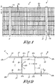
figure 1 schematically shows a fence according to the invention; -
figure 2 shows a cross-section according to line II-II infigure 1 ; -
figure 3 shows the folding lines along which a metal sheet is folded to make a fence post with a cross-section according tofigure 2 ; -
figure 4 shows a perspective view according to arrow F4 infigure 1 of an upper section of the fence with partial omission; -
figure 5 shows a cross-section according to line V-V infigure 4 ; -
figure 6 shows a view according to arrow F6 infigure 5 ; -
figure 7 shows a view of the die cut from which the part indicated by F7 infigure 6 is made; -
figure 8 shows a component of a fence according to the invention; -
figures 9 and 10 show alternative embodiments of a fence according to the invention; -
figure 11 shows a cross-section according to line XI-XI infigure 4 , but with a fence post provided with a cap. - The fence 1 shown in
figure 1 is constructed fromvertical fence posts 2 which are driven in the ground 3 for example and between which panels 4 are attached. - In the example shown the panels 4 are mesh panels which are composed of wires 5 or rods attached to each other, respectively straight rigid wires 5a which at different heights are always enclosed between two horizontal rigid straight wires 5 at a vertical distance A from each other.
- In the technical jargon such panels 4 are called 2D panels which exist in different sizes and which are typified by the diameters of the wires 5. For example,
2D panels 8/6/8 exist, referring to twohorizontal wires 5b of 8 mm, with a vertical wire 5a of 6mm in between. Analogously,2D panels 6/5/6 also exist. - As shown in the cross-section of
figure 2 , thefence posts 2 are made in the form of an H-profile 6 with twoopposite grooves 7 on either side of thefence post 2 where a panel 4 with a wire 5a fits and is attached in theside edge 8 of the panel 4, for example by means of aclip 9 as shown infigure 4 . - According to the invention, the
fence posts 2 are made of one single metal sheet or band 10 of which a strip with limited length A is shown infigure 3 and which breadthways B is folded between twoside edges 11 along folding lines 12, respectively foldinglines side edges 11 to form the H-profile 6 as shown infigure 2 with a tubular square central part 13 andlegs 14 which delimit thegrooves 7 and lie in each other's extension in pairs. - More specifically, the folding lines 12 delimit a number of vertical bands which correspond with folding sections of the H-
profile 6, respectively bands andfolding sections - On the level of the
folding lines 12a, the sheet or band 10 is folded over in a straight angle to form the corners of the tubular square central part 13, whereas on the level of thefolding lines 12b the sheet or band 10 is folded over double over 180° until the plate parts touch on either side of thefolding line 12b to form thelegs 14 with thefolding lines 12b on the level of the free ends of thelegs 14. - The sheet or band 10 is folded such that the
side edges 11 touch or practically touch, such that saidside edges 11 of thebands 15 can be connected with each other by awelded joint 20. - The
bands 17 form flatparallel flanks 21 of the H-profile 6, whereas the welded togetherbands 15 and theband 19 form thetransversal walls 22 between theflanks 17. - By folding a sheet or band 10 with thickness C of for example 1.25 mm in this way, a firm and slender tubular square central part 13 is obtained with a single thickness C of 1.25 mm and
legs 14 with a double thickness D of approximately 2.50 mm. - The panels 4 are attached in the
grooves 7 with theirside edges 8, as shown infigure 4 , by means ofclips 9, as shown in thefigures 4 to 6 . - The
clips 9 are formed from diecut platelets 23 for example as shown infigure 7 with a narrowed lip-shaped part 24 which is folded over along afolding zone 25 to form a U-shaped hook-shaped folded overpart 25 with which theclip 9 can be fittingly hooked over atransverse wall 22 of thefence post 2 as shown in thefigures 4 to 6 and if necessary can be attached to it by means of a screw, rivet or the like. - Furthermore, at a distance from the
folding zone 25, theplatelet 23 is folded over at right angles along afolding line 27 to form arectangular support platelet 28 extending toward thegroove 7 with a width E which fits between thelegs 14 of the H-profile (6) with a minimum clearance S relative to the width F of thegroove 7 and a length which approximately corresponds with the depth of thegroove 7. Thefolding line 27 also forms a supportingedge 27 with which thesupport platelet 28 rests against atransverse wall 22 of the H-profile 6, saidtransverse wall 22 also forming the bottom of thegroove 7. - About three grooves 29 are provided in the
support platelet 28 which extend essentially perpendicular to the direction of thefolding line 27 at a distance from each other, respectively twoouter grooves central groove 29c. - The
outer grooves groove 30 which is essentially parallel to thefolding line 27 and which at one end is connected with adie cut entry 31 in a corner of thesupport platelet 28 for a vertical wire 5a on theside edge 8 of a panel 4, saidentry 31 tapering off conically from the contour of thesupport platelet 28 onwards and ending in the connectinggroove 30. - It is not excluded that the connecting
groove 30 runs essentially parallel with only a part thefolding line 27 or is at an angle with a part or the entire folding line. - The
outer grooves groove 30 in the direction of thefolding line 27 toward each other. - The
central groove 29c extends perpendicularly to and on both sides of the connectinggroove 30. - The
grooves 29 and 30 have a width of approximately 6mm, such that they can contain all most common wire diameters of vertical wires 5a. -
Figure 4 shows that a 2D panel 4 is attached in a clip by hooking the panel with avertical wire 5b via theentry 31 in thecentral groove 29c, as shown infigure 4 , and lowering the panel 4 until twohorizontal wires 5b rest on thesupport platelet 28. - However, the
clip 9 is designed such that hooking is not possible with an installedclip 9 without first lifting the panel with theupper wires 5b above the top of thefence post 2 and slightly tilting it. - For this purpose, the
support platelet 28 is executed such that in a mounted condition of thesupport platelet 28, the smallest width G of theentry 31 measured relative to a side edge of thesupport platelet 28 and increased with the clearance S is smaller than the sum of the diameters of a wire 5a and awire 5b, such that a panel 4 which rests with itsupper wires 5b on thesupport platelet 28 cannot go through said narrowest width of the entry 13, neither for inserting a vertical wire 5a, nor for retracting it from a groove 29 of thesupport platelet 28, not even when thesupport platelet 28 is completely slid in thegroove 7 up against theleg 14 on the opposite side of theentry 31 as shown infigure 2 . - In this way it is prevented that once the panel 4 is positioned between two
fence posts 2, the panel is removed without breaking and the fence 1 is protected against theft as it were. - The panel 4 is held in place between the fence posts by the
spacers 32, as shown infigure 8 , in the form of blocks which fit in thegrooves 7 of thefence posts 2 and which are provided with agroove 33 in which an outer vertical wire 5a fits. - For extra security, a
cap 34 can be clamped at the top of thefence post 2 as shown infigure 11 , which for example is provided with a clamping part that is clamped in the tubular square central part 13 of thefence post 2. - Assuming that the
clips 9 are secured, a mounted panel 4, even in the absence of acap 34, can only be lifted up over a limited height corresponding with the distance A between thewires 5b in theclips 9, which prevents the panel 4 from being sufficiently tilted to remove the panel from the clip. - According to a practical embodiment of a
support platelet 28 which is suitable for mounting all commonly used types of panels 4, both 2D panels and 3D panels, thesupport platelet 28 is executed with a width G of the narrowest opening of theentry 31 of approximately 9mm. - It is noted that for mounting the panels 4 not a single tool is needed apart from possibly a tool to screw the
clips 9 on thefence posts 2 or the like. - The
figures 9 and 10 show the mounting of a 3D panel 4 whereby the vertical wires 5a are not straight as with the 2D panels, but contain triangular curved parts which protrude from the plane of the panel, either forward as shown infigure 9 or backward as shown infigure 10 . - In the case of such 3D panels 4, the
groove 29a or thegroove 29b is used for attaching a vertical wire 5a and this depending on the situation offigure 9 or figure 10 . - It is understood that the fence posts, instead of mesh panels 4, can also be used for solid plates or beams which are slid in the
grooves 7 with their ends. - In the same way the
clips 9 can also be applied on other fence posts than described here, for example clips without hook-shaped section but with a lip instead with which the clip is attached in agroove 7 of a fence post. - It is also clear that the
support platelet 28 is specifically executed for one of said assemblies of a panel 4 and to this end is only provided with one single groove 29. Two or more than three grooves 29 is not excluded either, depending on the type of panels that need to be mounted. - The present invention is by no means limited to the embodiments described as an example and shown in the figures, but a clip and a fence according to the invention can be realised in all kinds of forms and dimensions without departing from the scope of the invention.
Claims (15)
- Clip for attaching a panel in a fence, particularly a mesh panel with vertical and horizontal wires (5), whereby the panel (4) is mounted between vertical fence posts (2) in the form of a profile (6) with grooves (7) delimited by parallel legs (14) of the profile and whereby the panel (4) is attached with its side edges (8) in the grooves (7) of the profile (6), characterised in that the clip (9) contains a support platelet (28) with a width (E) delimited between two side edges and a supporting edge (27) to rest against the bottom (22) of the groove (7), said support platelet (28) being intended to be attached horizontally in said groove (7) of the fence post (2) to support a horizontal wire (5b) of the panel (4) and containing at least one groove (29) for a vertical wire (5a) on said side edge (8) of the panel (4), whereby said groove (29) is essentially perpendicular to said supporting edge (27) and whereby said groove (29) is connected with an edge of the support platelet (28) via an entry (31) for the vertical wire (5a) and via a connecting groove (30) which is at least in part parallel or at an angle with the supporting edge (27).
- Clip according to claim 1, characterised in that the support platelet (28) is a rectangular platelet with a width (E), which, apart from a lateral clearance S, is essentially equal to the width (F) of the groove (7) and a length which is practically equal to the depth of the groove (7) and that said entry (31) is machined in a corner of the support platelet (28) on the opposite edge of said supporting edge (27) .
- Clip according to claim 1 or 2, characterised in that the at least one groove (29) is connected with the entry (31) via a connecting groove (30) which is essentially parallel with the supporting edge (27).
- Clip according to claim 3, characterised in that at least two grooves (29) are provided at a lateral distance from each other and that said grooves (29) are connected with the entry (31) via a connecting groove (30) essentially parallel with the supporting edge (27).
- Clip according to claim 4, characterised in that there are at least two outer grooves (29a, 29b) which are each located at a same lateral distance from an adjacent side edge of the support platelet (28).
- Clip according to any one of the claims 3 to 5, characterised in that there is at least one central groove (29c) which is located in the middle between the two side edges of the support platelet (28).
- Clip according to claim 5 and 6, characterised in that there are at least three grooves (29), respectively at least two outer grooves (29a, 29b) and a central groove (29c) located in between, which (31) are connected with the entry via a connecting groove (30) which is essentially parallel with the supporting edge (27).
- Clip according to any one of the claims 5 to 7, characterised in that the outer grooves (29a and 29b) taper toward each other slightly from the connecting groove (30) in the direction of the supporting edge (27).
- Clip according to any one of the previous claims, characterised in that the width of the grooves is not wider than 6mm.
- Clip according to any one of the previous claims, characterised in that the entry (31) tapers off conically from the contour of the support platelet (28) onwards and ends in the connecting groove (30).
- Clip according to claim 10, characterised in that the smallest width (G) of the entry (31), measured relative to a side edge of the support platelet (28), is such that in a mounted condition of the support platelet (28) with a lateral clearance (S) in a groove (7), this smallest width (G) increased with said clearance (S) is smaller than the sum of the diameters of a vertical wire (5a) and a horizontal wire (5b) of the panel (4).
- Clip according to claim 11, characterised in that said smallest width (G) of the entry (31) amounts to approximately 9 mm.
- Clip according to any one of the previous claims, characterised in that the clip is made of a metal platelet, a part of which is folded over at right angles in relation to the support platelet (38) for attaching against the bottom (22) of a groove (7) of the fence post (2).
- Fence composed of fence posts (2) in the form of a profile (6) with grooves (7) with a bottom (22) and panels (4) attached between the fence posts and composed of vertical and horizontal wires (5) which together form a mesh panel with a side edge (8) attached in a groove (7), characterised in that the panel (4) is attached with vertical wire (5a) in the groove (7) by means of a clip (9) according to one of the previous claims which with its supporting edge (27) is oriented toward the bottom of the groove (7) of the fence post (2), whereby the relevant vertical wire (5a) is enclosed in one of the grooves (29) of the support platelet (28) which extend perpendicularly to the supporting edge (27) of the support platelet (28), essentially parallel with the legs (14) of the groove (7) of the fence post (2) and whereby the panel (4) with a horizontal wire (5b) rests on the support platelet (18).
- Fence according to claim 14, characterised in that the fence posts (2) are formed as a hollow H-profile (6) folded from one piece of a metal sheet or band, whereby the bottom of the groove (7) is formed by a transverse wall and that the clip (9) contains a hook-shaped part (26) with which the clip can be fittingly hooked over the transverse wall (22) and that the fence posts (2) are covered at the top by a cap 34 with a clamping part that is clamped in the hollow fence post (2).
Applications Claiming Priority (1)
| Application Number | Priority Date | Filing Date | Title |
|---|---|---|---|
| BE20205013A BE1027973B1 (en) | 2020-01-09 | 2020-01-09 | Clips for fixing a wire panel in a fence with support posts and fence fitted with them |
Publications (3)
| Publication Number | Publication Date |
|---|---|
| EP3848538A1 true EP3848538A1 (en) | 2021-07-14 |
| EP3848538B1 EP3848538B1 (en) | 2025-04-16 |
| EP3848538C0 EP3848538C0 (en) | 2025-04-16 |
Family
ID=69191837
Family Applications (1)
| Application Number | Title | Priority Date | Filing Date |
|---|---|---|---|
| EP21150294.3A Active EP3848538B1 (en) | 2020-01-09 | 2021-01-05 | Fence with clip for attaching a mesh panel between fence posts |
Country Status (2)
| Country | Link |
|---|---|
| EP (1) | EP3848538B1 (en) |
| BE (1) | BE1027973B1 (en) |
Cited By (1)
| Publication number | Priority date | Publication date | Assignee | Title |
|---|---|---|---|---|
| BE1029547B1 (en) * | 2021-11-05 | 2023-01-27 | Van Merksteijn Fences Netherlands | FENCE COMPRISING POSTS BETWEEN PANELS ARE MOUNTED |
Citations (6)
| Publication number | Priority date | Publication date | Assignee | Title |
|---|---|---|---|---|
| EP1054122A1 (en) * | 1999-05-21 | 2000-11-22 | Plastil Société Anonyme | Clip for fixing fence panels on grooved profiles |
| FR2908440A1 (en) | 2006-11-10 | 2008-05-16 | Moreda Riviere Trefilerias S A | Gyratory fixation piece for e.g. grid panel in sports ground, has housing embracing vertical rods of grid panel, and through hole allowing introduction of screw that fixes position of piece on double T-shaped vertical fence profile |
| EP2251507A1 (en) * | 2009-05-11 | 2010-11-17 | Joze Kocevar | Pole with a fastening element for a wire fence |
| US20140215957A1 (en) * | 2013-02-01 | 2014-08-07 | Usg Interiors, Llc | Clip for perimeter trim |
| EP2915936A2 (en) * | 2014-03-03 | 2015-09-09 | Dirickx Groupe | Connection between a fence and a post |
| EP3521536A1 (en) | 2018-02-01 | 2019-08-07 | Picot | Part for attaching at least one mesh panel to a fence post, corresponding fence post and installation tool |
-
2020
- 2020-01-09 BE BE20205013A patent/BE1027973B1/en active IP Right Grant
-
2021
- 2021-01-05 EP EP21150294.3A patent/EP3848538B1/en active Active
Patent Citations (6)
| Publication number | Priority date | Publication date | Assignee | Title |
|---|---|---|---|---|
| EP1054122A1 (en) * | 1999-05-21 | 2000-11-22 | Plastil Société Anonyme | Clip for fixing fence panels on grooved profiles |
| FR2908440A1 (en) | 2006-11-10 | 2008-05-16 | Moreda Riviere Trefilerias S A | Gyratory fixation piece for e.g. grid panel in sports ground, has housing embracing vertical rods of grid panel, and through hole allowing introduction of screw that fixes position of piece on double T-shaped vertical fence profile |
| EP2251507A1 (en) * | 2009-05-11 | 2010-11-17 | Joze Kocevar | Pole with a fastening element for a wire fence |
| US20140215957A1 (en) * | 2013-02-01 | 2014-08-07 | Usg Interiors, Llc | Clip for perimeter trim |
| EP2915936A2 (en) * | 2014-03-03 | 2015-09-09 | Dirickx Groupe | Connection between a fence and a post |
| EP3521536A1 (en) | 2018-02-01 | 2019-08-07 | Picot | Part for attaching at least one mesh panel to a fence post, corresponding fence post and installation tool |
Cited By (2)
| Publication number | Priority date | Publication date | Assignee | Title |
|---|---|---|---|---|
| BE1029547B1 (en) * | 2021-11-05 | 2023-01-27 | Van Merksteijn Fences Netherlands | FENCE COMPRISING POSTS BETWEEN PANELS ARE MOUNTED |
| EP4177424A1 (en) * | 2021-11-05 | 2023-05-10 | Van Merksteijn Fences-Netherlands B.V. | Fence, kit for producing a fence and related method for producing a fence |
Also Published As
| Publication number | Publication date |
|---|---|
| EP3848538B1 (en) | 2025-04-16 |
| BE1027973A1 (en) | 2021-08-03 |
| BE1027973B1 (en) | 2021-08-10 |
| EP3848538C0 (en) | 2025-04-16 |
Similar Documents
| Publication | Publication Date | Title |
|---|---|---|
| US4582001A (en) | Shelf connector assembly | |
| US5725137A (en) | Carrier rack and rack retainer | |
| US4455007A (en) | Hang rail support and hang rail | |
| US6467230B1 (en) | Interconnection device and method for securing a safety rail | |
| US5876165A (en) | Dunnage bar | |
| JPS645950B2 (en) | ||
| GB2140670A (en) | Safety steel angle assembly rack | |
| US20180328053A1 (en) | Support head, ceiling support, and ceiling formwork having such a ceiling support | |
| EP3848538B1 (en) | Fence with clip for attaching a mesh panel between fence posts | |
| US4540309A (en) | Attachment device | |
| US4930732A (en) | Yoke pipe clip | |
| GB2278919A (en) | End cap for the I-shaped frame of a spirit level | |
| EP0387964B1 (en) | Suspension system for ceiling panels and a sectional bar for such a system | |
| DE19834370C1 (en) | Fastening for basin or drain in cover plate | |
| US3160281A (en) | Partition structure | |
| US3975106A (en) | Builders scaffolding | |
| EP0849516B1 (en) | Mounting member with a pipe clamp or a similar fastening member | |
| EP3848539B1 (en) | Fence post for a fence and fence equipped therewith | |
| JPH0433290Y2 (en) | ||
| JP6189367B2 (en) | Solar panel mounting bracket | |
| JP3170759U (en) | Anti-theft device for grating | |
| EP0861942B1 (en) | Structure for mounting sound absorbing member on top portion of sound insulation wall and method of mounting the same | |
| JPH0233947Y2 (en) | ||
| EP2826402B1 (en) | Vertical column configured to equip a lateral panel of a shelving device, lateral panel comprising such vertical columns and shelving device comprising such lateral panels | |
| FI86460B (en) | TAKSTEGE. |
Legal Events
| Date | Code | Title | Description |
|---|---|---|---|
| PUAI | Public reference made under article 153(3) epc to a published international application that has entered the european phase |
Free format text: ORIGINAL CODE: 0009012 |
|
| STAA | Information on the status of an ep patent application or granted ep patent |
Free format text: STATUS: THE APPLICATION HAS BEEN PUBLISHED |
|
| AK | Designated contracting states |
Kind code of ref document: A1 Designated state(s): AL AT BE BG CH CY CZ DE DK EE ES FI FR GB GR HR HU IE IS IT LI LT LU LV MC MK MT NL NO PL PT RO RS SE SI SK SM TR |
|
| STAA | Information on the status of an ep patent application or granted ep patent |
Free format text: STATUS: REQUEST FOR EXAMINATION WAS MADE |
|
| 17P | Request for examination filed |
Effective date: 20211103 |
|
| RBV | Designated contracting states (corrected) |
Designated state(s): AL AT BE BG CH CY CZ DE DK EE ES FI FR GB GR HR HU IE IS IT LI LT LU LV MC MK MT NL NO PL PT RO RS SE SI SK SM TR |
|
| STAA | Information on the status of an ep patent application or granted ep patent |
Free format text: STATUS: EXAMINATION IS IN PROGRESS |
|
| 17Q | First examination report despatched |
Effective date: 20230330 |
|
| GRAP | Despatch of communication of intention to grant a patent |
Free format text: ORIGINAL CODE: EPIDOSNIGR1 |
|
| STAA | Information on the status of an ep patent application or granted ep patent |
Free format text: STATUS: GRANT OF PATENT IS INTENDED |
|
| INTG | Intention to grant announced |
Effective date: 20241217 |
|
| GRAS | Grant fee paid |
Free format text: ORIGINAL CODE: EPIDOSNIGR3 |
|
| GRAA | (expected) grant |
Free format text: ORIGINAL CODE: 0009210 |
|
| STAA | Information on the status of an ep patent application or granted ep patent |
Free format text: STATUS: THE PATENT HAS BEEN GRANTED |
|
| AK | Designated contracting states |
Kind code of ref document: B1 Designated state(s): AL AT BE BG CH CY CZ DE DK EE ES FI FR GB GR HR HU IE IS IT LI LT LU LV MC MK MT NL NO PL PT RO RS SE SI SK SM TR |
|
| REG | Reference to a national code |
Ref country code: GB Ref legal event code: FG4D |
|
| REG | Reference to a national code |
Ref country code: CH Ref legal event code: EP |
|
| REG | Reference to a national code |
Ref country code: IE Ref legal event code: FG4D |
|
| U01 | Request for unitary effect filed |
Effective date: 20250416 |
|
| U07 | Unitary effect registered |
Designated state(s): AT BE BG DE DK EE FI FR IT LT LU LV MT NL PT RO SE SI Effective date: 20250424 |
|
| PG25 | Lapsed in a contracting state [announced via postgrant information from national office to epo] |
Ref country code: ES Free format text: LAPSE BECAUSE OF FAILURE TO SUBMIT A TRANSLATION OF THE DESCRIPTION OR TO PAY THE FEE WITHIN THE PRESCRIBED TIME-LIMIT Effective date: 20250416 |
|
| PG25 | Lapsed in a contracting state [announced via postgrant information from national office to epo] |
Ref country code: GR Free format text: LAPSE BECAUSE OF FAILURE TO SUBMIT A TRANSLATION OF THE DESCRIPTION OR TO PAY THE FEE WITHIN THE PRESCRIBED TIME-LIMIT Effective date: 20250717 Ref country code: NO Free format text: LAPSE BECAUSE OF FAILURE TO SUBMIT A TRANSLATION OF THE DESCRIPTION OR TO PAY THE FEE WITHIN THE PRESCRIBED TIME-LIMIT Effective date: 20250716 |
|
| PG25 | Lapsed in a contracting state [announced via postgrant information from national office to epo] |
Ref country code: PL Free format text: LAPSE BECAUSE OF FAILURE TO SUBMIT A TRANSLATION OF THE DESCRIPTION OR TO PAY THE FEE WITHIN THE PRESCRIBED TIME-LIMIT Effective date: 20250416 |
|
| PG25 | Lapsed in a contracting state [announced via postgrant information from national office to epo] |
Ref country code: HR Free format text: LAPSE BECAUSE OF FAILURE TO SUBMIT A TRANSLATION OF THE DESCRIPTION OR TO PAY THE FEE WITHIN THE PRESCRIBED TIME-LIMIT Effective date: 20250416 |
|
| PG25 | Lapsed in a contracting state [announced via postgrant information from national office to epo] |
Ref country code: RS Free format text: LAPSE BECAUSE OF FAILURE TO SUBMIT A TRANSLATION OF THE DESCRIPTION OR TO PAY THE FEE WITHIN THE PRESCRIBED TIME-LIMIT Effective date: 20250716 |
|
| PG25 | Lapsed in a contracting state [announced via postgrant information from national office to epo] |
Ref country code: IS Free format text: LAPSE BECAUSE OF FAILURE TO SUBMIT A TRANSLATION OF THE DESCRIPTION OR TO PAY THE FEE WITHIN THE PRESCRIBED TIME-LIMIT Effective date: 20250816 |
|
| PG25 | Lapsed in a contracting state [announced via postgrant information from national office to epo] |
Ref country code: SM Free format text: LAPSE BECAUSE OF FAILURE TO SUBMIT A TRANSLATION OF THE DESCRIPTION OR TO PAY THE FEE WITHIN THE PRESCRIBED TIME-LIMIT Effective date: 20250416 |
|
| PG25 | Lapsed in a contracting state [announced via postgrant information from national office to epo] |
Ref country code: CZ Free format text: LAPSE BECAUSE OF FAILURE TO SUBMIT A TRANSLATION OF THE DESCRIPTION OR TO PAY THE FEE WITHIN THE PRESCRIBED TIME-LIMIT Effective date: 20250416 |
|
| PG25 | Lapsed in a contracting state [announced via postgrant information from national office to epo] |
Ref country code: SK Free format text: LAPSE BECAUSE OF FAILURE TO SUBMIT A TRANSLATION OF THE DESCRIPTION OR TO PAY THE FEE WITHIN THE PRESCRIBED TIME-LIMIT Effective date: 20250416 |
|
| PLBE | No opposition filed within time limit |
Free format text: ORIGINAL CODE: 0009261 |
|
| STAA | Information on the status of an ep patent application or granted ep patent |
Free format text: STATUS: NO OPPOSITION FILED WITHIN TIME LIMIT |
|
| REG | Reference to a national code |
Ref country code: CH Ref legal event code: L10 Free format text: ST27 STATUS EVENT CODE: U-0-0-L10-L00 (AS PROVIDED BY THE NATIONAL OFFICE) Effective date: 20260225 |
|
| U20 | Renewal fee for the european patent with unitary effect paid |
Year of fee payment: 6 Effective date: 20260128 |
|
| 26N | No opposition filed |
Effective date: 20260119 |