EP3848497A1 - Laundry treatment apparatus - Google Patents
Laundry treatment apparatus Download PDFInfo
- Publication number
- EP3848497A1 EP3848497A1 EP20215073.6A EP20215073A EP3848497A1 EP 3848497 A1 EP3848497 A1 EP 3848497A1 EP 20215073 A EP20215073 A EP 20215073A EP 3848497 A1 EP3848497 A1 EP 3848497A1
- Authority
- EP
- European Patent Office
- Prior art keywords
- door
- door plate
- door hole
- hole
- along
- Prior art date
- Legal status (The legal status is an assumption and is not a legal conclusion. Google has not performed a legal analysis and makes no representation as to the accuracy of the status listed.)
- Withdrawn
Links
- 238000013459 approach Methods 0.000 claims abstract description 36
- 230000007246 mechanism Effects 0.000 claims abstract description 26
- 230000005540 biological transmission Effects 0.000 claims abstract description 8
- 238000007789 sealing Methods 0.000 claims description 11
- 230000002093 peripheral effect Effects 0.000 claims description 7
- 230000003247 decreasing effect Effects 0.000 claims description 4
- 238000005406 washing Methods 0.000 description 13
- 238000010586 diagram Methods 0.000 description 10
- 230000009286 beneficial effect Effects 0.000 description 2
- 230000000903 blocking effect Effects 0.000 description 2
- 230000001419 dependent effect Effects 0.000 description 1
- 238000001035 drying Methods 0.000 description 1
- 230000000694 effects Effects 0.000 description 1
- 238000005516 engineering process Methods 0.000 description 1
- 238000007731 hot pressing Methods 0.000 description 1
- 230000006872 improvement Effects 0.000 description 1
- 238000000034 method Methods 0.000 description 1
- 230000004048 modification Effects 0.000 description 1
- 238000012986 modification Methods 0.000 description 1
- 229920003023 plastic Polymers 0.000 description 1
- 229920001296 polysiloxane Polymers 0.000 description 1
- 230000008569 process Effects 0.000 description 1
- 239000005341 toughened glass Substances 0.000 description 1
- 239000012780 transparent material Substances 0.000 description 1
- 238000009736 wetting Methods 0.000 description 1
Images



Classifications
-
- D—TEXTILES; PAPER
- D06—TREATMENT OF TEXTILES OR THE LIKE; LAUNDERING; FLEXIBLE MATERIALS NOT OTHERWISE PROVIDED FOR
- D06F—LAUNDERING, DRYING, IRONING, PRESSING OR FOLDING TEXTILE ARTICLES
- D06F39/00—Details of washing machines not specific to a single type of machines covered by groups D06F9/00 - D06F27/00
- D06F39/12—Casings; Tubs
-
- D—TEXTILES; PAPER
- D06—TREATMENT OF TEXTILES OR THE LIKE; LAUNDERING; FLEXIBLE MATERIALS NOT OTHERWISE PROVIDED FOR
- D06F—LAUNDERING, DRYING, IRONING, PRESSING OR FOLDING TEXTILE ARTICLES
- D06F39/00—Details of washing machines not specific to a single type of machines covered by groups D06F9/00 - D06F27/00
- D06F39/12—Casings; Tubs
- D06F39/14—Doors or covers; Securing means therefor
-
- D—TEXTILES; PAPER
- D06—TREATMENT OF TEXTILES OR THE LIKE; LAUNDERING; FLEXIBLE MATERIALS NOT OTHERWISE PROVIDED FOR
- D06F—LAUNDERING, DRYING, IRONING, PRESSING OR FOLDING TEXTILE ARTICLES
- D06F25/00—Washing machines with receptacles, e.g. perforated, having a rotary movement, e.g. oscillatory movement, the receptacle serving both for washing and for centrifugally separating water from the laundry and having further drying means, e.g. using hot air
Definitions
- This application relates to the field of washing machine technologies, and in particular, to a laundry treatment apparatus.
- a washing machine is a relatively common laundry treatment apparatus in our daily life. Whether it is an up-loaded washing machine or a front-loaded washing machine, a door plate of the washing machine is generally hinged to a door hole of a housing of the washing machine, and the door hole is uncovered after the door plate is generally turned by a specific angle. However, when in an open state, the door plate occupies a relatively large external space of the housing of the washing machine. A sufficient space needs to be reserved when the washing machine is installed and placed, to ensure that the door plate of the washing machine can be normally opened.
- the door plate is embedded in the middle of a housing wall where the door hole is provided.
- the door hole can be uncovered or covered when the door plate moves in the cavity.
- this significantly increases the thickness of the housing wall and the structural complexity.
- this application provides a laundry treatment apparatus, to resolve the problem in the prior art that when being opened, a door plate of a washing machine occupies a relatively large external space or results in a complex structure of a housing wall of the washing machine shell.
- the laundry treatment apparatus includes a housing, a door plate, and a driving mechanism.
- the housing is provided with a door hole.
- the door plate is used for covering the door hole.
- the driving mechanism is disposed on the housing and is in transmission connection with the door plate, and is used for driving the door plate to approach or move away from the door hole along a horizontal direction and approach or move away from the door hole along a vertical direction.
- the door plate When the door hole is uncovered, the door plate first moves away from the door hole along the horizontal direction and then moves away from the door hole along the vertical direction.
- the door plate When the door hole is covered, the door plate first approaches the door hole along the vertical direction and then approaches the door hole along the horizontal direction.
- the driving mechanism includes a first driving member and a second driving member.
- One end of the first driving member is connected to a side of the door plate facing the door hole, and the other end is connected to the second driving member, for driving the door plate to approach or move away from the door hole along the horizontal direction.
- the second driving member is used for driving the first driving member to approach or move away from the door hole along the vertical direction.
- the first driving member is an electric telescopic frame
- the second driving member is a lifting motor
- the lifting motor includes a lead screw rotating shaft and a nut sleeved on the lead screw rotating shaft.
- One end of the electric telescopic frame is connected to a side of the door plate facing the door hole, and the other end is connected to the nut.
- the first driving member is an electric telescopic rod
- the second driving member is a lifting motor
- the lifting motor includes a lifting rack and a gear in meshing transmission with the lifting rack.
- One end of the electric telescopic rod is connected to one side of the door plate facing the door hole, and the other end is connected to the lifting rack.
- the housing is further provided with a recessed portion for receiving the door plate.
- the housing is further provided with a lifting seam in the recessed portion, and the first driving member penetrates the lifting seam and is connected to a lower side of the door plate.
- the housing is further provided with a recessed portion for receiving the door plate.
- the housing is further provided with a lifting seam in the recessed portion, and the first driving member penetrates the lifting seam and is connected to an upper side of the door plate.
- the housing is further provided with a recessed portion for receiving the door plate.
- the door plate includes a first door plate and a second door plate.
- the housing is further provided with a lifting seam in the recessed portion, and the first driving member penetrates the lifting seam and is connected to a lower side of the first door plate and an upper side of the second door plate respectively.
- a side of the door plate facing the door hole is further provided with a plugging portion used for plugging the door hole.
- the plugging portion is correspondingly plugged in the door hole.
- the plugging portion is configured as a frustum with a gradually decreasing diameter.
- the plugging portion includes an annular peripheral wall abutting against the door hole, and a sealing member is further disposed around the annular peripheral wall.
- the laundry treatment apparatus includes a housing, a door plate, and a driving mechanism.
- the housing is provided with a door hole, and the door plate is used for covering the door hole.
- the driving mechanism is disposed on the housing and is in transmission connection with the door plate, and is used for driving the door plate to approach or move away from the door hole along a horizontal direction and approach or move away from the door hole along a vertical direction.
- the door plate When the door hole is uncovered, the door plate first moves away from the door hole along the horizontal direction and then moves away from the door hole along the vertical direction; and when the door hole is covered, the door plate first approaches the door hole along the vertical direction and then approaches the door hole along the horizontal direction.
- the laundry treatment apparatus When the door hole is uncovered, the laundry treatment apparatus first drives, by using the driving mechanism, the door plate to move away from the door hole along the horizontal direction, and then drives, by using the driving mechanism, the door plate to move away from the door hole along the vertical direction, so that a function of uncovering the door hole can be implemented.
- the door plate is located at an interval on an outer side of the housing of the laundry treatment apparatus in parallel and occupies a relatively small external space when being opened.
- the laundry treatment apparatus When the door hole is covered, the laundry treatment apparatus first drives, by using the driving mechanism, the door plate to approach to be located right in front of the door hole along the vertical direction, and then drives, by using the driving mechanism, the door plate to approach to be attached to the door hole along the horizontal direction, so that the door plate covers the door hole. Moreover, in this case, because the door plate is attached to the outer side of the housing of the laundry treatment apparatus, a housing structure of the laundry treatment apparatus is not affected at all.
- the laundry treatment apparatus provided in this application has advantages that the door plate occupies a small external space when the door hole is uncovered, and the door plate does not affect the housing structure.
- orientation terms such as “above”, “below”, “left”, and “right” described in the embodiments of this application are described from views shown in the accompanying drawings, and should not be construed as a limitation to the embodiments of this application.
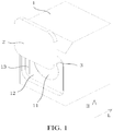
- FIG. 1 is a schematic structural diagram of a first solution of a laundry treatment apparatus according to an embodiment of this application.
- FIG. 2 is a schematic structural diagram of a second solution of a laundry treatment apparatus according to an embodiment of this application.
- FIG. 3 is a schematic structural diagram of a third solution of a laundry treatment apparatus according to an embodiment of this application.
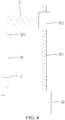
- FIG. 4 is a schematic structural diagram of a first solution of a driving mechanism in the laundry treatment apparatus according to an embodiment of this application.
- FIG. 5 is a schematic structural diagram of a second solution of a driving mechanism in the laundry treatment apparatus according to an embodiment of this application.
- an embodiment of this application provides a laundry treatment apparatus.
- the laundry treatment apparatus includes a housing 1, a door plate 2, and a driving mechanism 3.
- the housing 1 is provided with a door hole 11; the door plate 2 is used for covering the door hole 11; and the driving mechanism 3 is disposed on the housing 1 and is in transmission connection with the door plate 2, and is used for driving the door plate 2 to approach or move away from the door hole 11 along a horizontal direction L and approach or move away from the door hole 11 along a vertical direction H.
- the door plate 2 When the door hole 11 is uncovered, the door plate 2 first moves away from the door hole 11 along the horizontal direction L and then moves away from the door hole 11 along the vertical direction H; and when the door hole 11 is covered, the door plate 2 first approaches the door hole 11 along the vertical direction H and then approaches the door hole 11 along the horizontal direction L.
- the laundry treatment apparatus When the door hole 11 is uncovered, the laundry treatment apparatus first drives, by using the driving mechanism 3, the door plate 2 to move away from the door hole 11 along the horizontal direction L, and then drives, by using the driving mechanism 3, the door plate 2 to move away from the door hole 11 along the vertical direction H, so that a function of uncovering the door hole 11 can be implemented.
- the door plate 2 is located at an interval on an outer side of the housing of the laundry treatment apparatus in parallel and occupy a relatively small external space when being opened.
- the laundry treatment apparatus When the door hole 11 is covered, the laundry treatment apparatus first drives, by using the driving mechanism 3, the door plate 2 to approach to be right in front of the door hole 11 along the vertical direction H, and then drives, by using the driving mechanism 3, the door plate 2 to approach to be attached to the door hole 11 along the horizontal direction L, so that the door plate 2 covers the door hole 11. Moreover, in this case, because the door plate 2 is attached to the outer side of the housing of the laundry treatment apparatus, a housing structure of the laundry treatment apparatus is not affected at all.
- the laundry treatment apparatus has advantages that the door plate 2 occupies a small external space when the door hole 11 is uncovered, and the door plate 2 does not affect the housing structure.
- the laundry treatment apparatus may be an apparatus such as a washing machine, a drying machine, or a dryer.
- the driving mechanism 3 includes a first driving member 31 and a second driving member 32.
- One end of the first driving member 31 is connected to a side of the door plate 2 facing the door hole 11, and the other end is connected to the second driving member 32, for driving the door plate 2 to approach or move away from the door hole 11 along the horizontal direction L; and the second driving member 32 is used for driving the first driving member 31 to approach or move away from the door hole 11 along the vertical direction H.
- the driving mechanism 3 is configured as the foregoing first driving member 31 and the second driving member 32, and the function of covering or uncovering the door hole 11 by the door plate 2 is implemented in a manner that the first driving member 31 drives the door plate 2 to approach or move away from the door hole 11 along the horizontal direction L and the second driving member 32 drives the first driving member 31 to approach or move away from the door hole 11 along the vertical direction H, thereby achieving advantages of a simple structure and good driving stability.
- the first driving member 31 is an electric telescopic frame
- the second driving member 32 is a lifting motor.
- the lifting motor includes a lead screw rotating shaft 321 and a nut 322 sleeved on the lead screw rotating shaft 321.
- One end of the electric telescopic frame is connected to one side of the door plate 2 facing the door hole 11, and the other end is connected to the nut 322.
- the first driving member 31 is configured as an electric telescopic frame
- the second driving member 32 is configured as a lifting motor.
- the lead screw rotating shaft 321 of the lifting motor rotates forward or backward to drive the nut 322 to move up or down along the vertical direction H, and further drive the electric telescopic frame to move up or down along the vertical direction H, so that a function of driving the door plate 2 to approach or move away from the door hole 11 along the vertical direction H is implemented.
- the second driving member 32 is a main component for bearing the weight of the door plate 2
- the lead screw rotating shaft 321 of the lifting motor may stably and reliably bear the door plate 2.
- the lifting motor may be configured as a stepper motor, and by controlling an output rotation angle of the lifting motor, a lifting height of the door plate 2 along the vertical direction H can be controlled stably and accurately.
- the first driving member 31 is configured as the electric telescopic frame, and the second driving member 32 is configured as the lifting motor, thereby achieving advantages of a simple structure, driving stability, and good accuracy.
- both the first driving member 31 and the second driving member 32 may alternatively be configured as the foregoing electric telescopic frame, or the foregoing lifting motor.
- this embodiment further provides another optional solution of the first driving member 31 and the second driving member 32.
- the first driving member 31 is an electric telescopic rod
- the second driving member 32 is a lifting motor.
- the lifting motor includes a lifting rack 323 and a gear 324 in meshing transmission with the lifting rack 323.
- One end of the electric telescopic rod is connected to a side of the door plate 2 facing the door hole 11, and the other end is connected to the lifting rack 323.
- the first driving member 31 is configured as an electric telescopic rod
- the second driving member 32 is configured as a lifting motor.
- the gear 324 of the lifting motor rotates backward to drive the lifting rack 323 to move up or down along the vertical direction H, and further drive the electric telescopic frame to move up or down along the vertical direction H, so that a function of driving the door plate 2 to approach or move away from the door hole 11 along the vertical direction H can also be implemented.
- the lifting rack 323 can also bear the door plate 2 stably and reliably.
- the lifting motor is configured as a stepper motor, and by controlling an output rotation angle of the lifting motor, a lifting height of the door plate 2 along the vertical direction H is controlled stably and accurately.
- the first driving member 31 is configured as the electric telescopic rod, and the second driving member 32 is configured as the lifting motor, thereby also achieving advantages of a simple structure, driving stability, and good accuracy.
- both the first driving member 31 and the second driving member 32 may alternatively be configured as the foregoing electric telescopic rod, or the foregoing lifting motor.
- the housing 1 is further provided with a recessed portion 12 for receiving the door plate 2.
- the housing 1 is further provided with a lifting seam 13 in the recessed portion 12, and the first driving member 31 penetrates the lifting seam 13 and is connected to a lower side of the door plate 2.
- the door plate 2 when the door plate 2 covers the door hole 11, the door plate 2 may be received in the recessed portion 12, thereby reducing the external space occupied when the door plate 2 covers the door hole 11.
- the lifting seam 13 vertically provided in the recessed portion 12 may receive and limit the first driving member 31, to prevent the first driving member 31 from shaking side to side along the horizontal direction.
- the first driving member 31 penetrates the lifting seam 13 and is connected to the lower side of the door plate 2. In this way, when the door plate 2 uncovers the door hole 11, the first driving member 31 first drives the door plate 2 to move away from the door hole 11 along the horizontal direction L, and the second driving member 32 then drives the door plate 2 to move upward along the vertical direction H, so that the door hole 11 is uncovered.
- this embodiment further provides a second specific configuration solution of the door plate 2.
- the housing 1 On an outer side wall on which the door hole 11 is provided, the housing 1 is further provided with a recessed portion 12 for receiving the door plate 2.
- the housing 1 is further provided with a lifting seam 13 in the recessed portion 12, and the first driving member 31 penetrates the lifting seam 13 and is connected to an upper side of the door plate 2.
- the first driving member 31 penetrates the lifting seam 13 and is connected to the upper side of the door plate 2. In this way, when the door hole 11 is uncovered, the first driving member 31 first drives the door plate 2 to move away from the door hole 11 along the horizontal direction L, and the second driving member 32 then drives the door plate 2 to move downward along the vertical direction H, so that the door hole 11 is uncovered.
- this embodiment further provides a third specific configuration solution of the door plate 2.
- the housing 1 On an outer side wall on which the door hole 11 is provided, the housing 1 is further provided with a recessed portion 12 for receiving the door plate 2.
- the door plate 2 includes a first door plate 21 and a second door plate 22.
- the housing 1 is further provided with a lifting seam 13 in the recessed portion 12, and the first driving member 31 penetrates the lifting seam 13 and is connected to a lower side of the first door plate 21 and an upper side of the second door plate 22 respectively.
- the door plate 2 is configured as the first door plate 21 and the second door plate 22, and the first driving member 31 is connected to the lower side of the first door plate 21 and the upper side of the second door plate 22 respectively.
- the first driving member 31 first drives the door plate 2 to move away from the door hole 11 along the horizontal direction L, and the second driving member 32 then separately drives the first door plate 21 to move upward along the vertical direction H, and drives the second door plate 22 to move downward along the vertical direction H, so that the door hole 11 is uncovered.
- a side of the door plate 2 facing the door hole 11 is further provided with a plugging portion 23 used for plugging the door hole 11; and when the door plate 2 covers the door hole 11, the plugging portion 23 is correspondingly plugged in the door hole 11.
- the plugging portion 23 may be used for plugging and blocking the door hole 11 when the door plate 2 covers the door hole 11, to prevent moisture in the laundry treatment apparatus from wetting the door plate 2 through the door hole 11, and further improve a sealing effect of the door plate 2 for the door hole 11.
- the door plate 2 and the plugging portion 23 may be preferably made of a transparent material, such as transparent plastic, or transparent tempered glass.
- the plugging portion 23 is configured as a frustum with a gradually decreasing diameter.
- the plugging portion 23 is configured as the frustum with the gradually decreasing diameter.
- the plugging portion 23 in the shape of the frustum may be also plugged in the door hole 11, and when the plugging portion 23 in the shape of the frustum is fully plugged in the door hole 11, beneficial effects of adjusting and calibrating a relative position relationship between the door hole 11 and the door plate 2 can further be achieved.
- the plugging portion 23 includes an annular peripheral wall abutting against the door hole 11, and a sealing member 231 is further disposed around the annular peripheral wall.
- the sealing member 231 may be specifically configured as an annular sealing strip, such as a rubber sealing ring or a silicone sealing ring, and is fixed, by a process such as pasting or hot pressing and hot stamping, to the annular peripheral wall of the plugging portion 23 which abuts against the door hole 11.
- the foregoing sealing member 231 can further improve sealing performance of the plugging portion 23 for plugging and blocking the door hole 11.
Landscapes
- Engineering & Computer Science (AREA)
- Textile Engineering (AREA)
- Power-Operated Mechanisms For Wings (AREA)
Abstract
Description
- This application relates to the field of washing machine technologies, and in particular, to a laundry treatment apparatus.
- A washing machine is a relatively common laundry treatment apparatus in our daily life. Whether it is an up-loaded washing machine or a front-loaded washing machine, a door plate of the washing machine is generally hinged to a door hole of a housing of the washing machine, and the door hole is uncovered after the door plate is generally turned by a specific angle. However, when in an open state, the door plate occupies a relatively large external space of the housing of the washing machine. A sufficient space needs to be reserved when the washing machine is installed and placed, to ensure that the door plate of the washing machine can be normally opened.
- In the prior art, in some advanced washing machines, the door plate is embedded in the middle of a housing wall where the door hole is provided. By providing a cavity for the door plate to move in the housing wall, the door hole can be uncovered or covered when the door plate moves in the cavity. However, this significantly increases the thickness of the housing wall and the structural complexity.
- In view of this, this application provides a laundry treatment apparatus, to resolve the problem in the prior art that when being opened, a door plate of a washing machine occupies a relatively large external space or results in a complex structure of a housing wall of the washing machine shell.
- The laundry treatment apparatus provided in this application includes a housing, a door plate, and a driving mechanism.
- The housing is provided with a door hole.
- The door plate is used for covering the door hole.
- The driving mechanism is disposed on the housing and is in transmission connection with the door plate, and is used for driving the door plate to approach or move away from the door hole along a horizontal direction and approach or move away from the door hole along a vertical direction.
- When the door hole is uncovered, the door plate first moves away from the door hole along the horizontal direction and then moves away from the door hole along the vertical direction.
- When the door hole is covered, the door plate first approaches the door hole along the vertical direction and then approaches the door hole along the horizontal direction.
- In a possible design, the driving mechanism includes a first driving member and a second driving member.
- One end of the first driving member is connected to a side of the door plate facing the door hole, and the other end is connected to the second driving member, for driving the door plate to approach or move away from the door hole along the horizontal direction.
- The second driving member is used for driving the first driving member to approach or move away from the door hole along the vertical direction.
- In a possible design, the first driving member is an electric telescopic frame, and the second driving member is a lifting motor.
- The lifting motor includes a lead screw rotating shaft and a nut sleeved on the lead screw rotating shaft.
- One end of the electric telescopic frame is connected to a side of the door plate facing the door hole, and the other end is connected to the nut.
- In a possible design, the first driving member is an electric telescopic rod, and the second driving member is a lifting motor.
- The lifting motor includes a lifting rack and a gear in meshing transmission with the lifting rack.
- One end of the electric telescopic rod is connected to one side of the door plate facing the door hole, and the other end is connected to the lifting rack.
- In a possible design, on an outer side wall on which the door hole is provided, the housing is further provided with a recessed portion for receiving the door plate.
- Along the vertical direction, the housing is further provided with a lifting seam in the recessed portion, and the first driving member penetrates the lifting seam and is connected to a lower side of the door plate.
- In a possible design, on an outer side wall on which the door hole is provided, the housing is further provided with a recessed portion for receiving the door plate.
- Along the vertical direction, the housing is further provided with a lifting seam in the recessed portion, and the first driving member penetrates the lifting seam and is connected to an upper side of the door plate.
- In a possible design, on an outer side wall on which the door hole is provided, the housing is further provided with a recessed portion for receiving the door plate.
- The door plate includes a first door plate and a second door plate.
- Along the vertical direction, the housing is further provided with a lifting seam in the recessed portion, and the first driving member penetrates the lifting seam and is connected to a lower side of the first door plate and an upper side of the second door plate respectively.
- In a possible design, a side of the door plate facing the door hole is further provided with a plugging portion used for plugging the door hole.
- When the door plate covers the door hole, the plugging portion is correspondingly plugged in the door hole.
- In a possible design, along a direction toward the door hole, the plugging portion is configured as a frustum with a gradually decreasing diameter.
- In a possible design, the plugging portion includes an annular peripheral wall abutting against the door hole, and a sealing member is further disposed around the annular peripheral wall.
- With reference to the foregoing technical solutions, the beneficial effects of this application are analyzed as follows:
The laundry treatment apparatus provided in this application includes a housing, a door plate, and a driving mechanism. The housing is provided with a door hole, and the door plate is used for covering the door hole. The driving mechanism is disposed on the housing and is in transmission connection with the door plate, and is used for driving the door plate to approach or move away from the door hole along a horizontal direction and approach or move away from the door hole along a vertical direction. When the door hole is uncovered, the door plate first moves away from the door hole along the horizontal direction and then moves away from the door hole along the vertical direction; and when the door hole is covered, the door plate first approaches the door hole along the vertical direction and then approaches the door hole along the horizontal direction. - When the door hole is uncovered, the laundry treatment apparatus first drives, by using the driving mechanism, the door plate to move away from the door hole along the horizontal direction, and then drives, by using the driving mechanism, the door plate to move away from the door hole along the vertical direction, so that a function of uncovering the door hole can be implemented. Moreover, in this case, the door plate is located at an interval on an outer side of the housing of the laundry treatment apparatus in parallel and occupies a relatively small external space when being opened. When the door hole is covered, the laundry treatment apparatus first drives, by using the driving mechanism, the door plate to approach to be located right in front of the door hole along the vertical direction, and then drives, by using the driving mechanism, the door plate to approach to be attached to the door hole along the horizontal direction, so that the door plate covers the door hole. Moreover, in this case, because the door plate is attached to the outer side of the housing of the laundry treatment apparatus, a housing structure of the laundry treatment apparatus is not affected at all.
- Based on the foregoing, the laundry treatment apparatus provided in this application has advantages that the door plate occupies a small external space when the door hole is uncovered, and the door plate does not affect the housing structure.
- Other features and advantages of the embodiments of this application are described in a subsequent specification, and are partially apparent from the specification, or are understood by implementing the embodiments of this application. An objective and other advantages of the embodiments of this application are achieved and obtained in structures that are specially pointed out in the specification and the accompanying drawings.
-
FIG. 1 is a schematic structural diagram of a first solution of a laundry treatment apparatus according to an embodiment of this application; -
FIG. 2 is a schematic structural diagram of a second solution of a laundry treatment apparatus according to an embodiment of this application; -
FIG. 3 is a schematic structural diagram of a third solution of a laundry treatment apparatus according to an embodiment of this application; -
FIG. 4 is a schematic structural diagram of a first solution of a driving mechanism in the laundry treatment apparatus according to an embodiment of this application; and -
FIG. 5 is a schematic structural diagram of a second solution of a driving mechanism in the laundry treatment apparatus according to an embodiment of this application. -
- 1-housing;
- 11-door hole;
- 12-recessed portion;
- 13-lifting seam;
- 2-door plate;
- 21-first door plate;
- 22-second door plate;
- 23-plugging portion;
- 231-sealing member;
- 3-driving mechanism;
- 31-first driving member;
- 32-second driving member;
- 321-lead screw rotating shaft;
- 322-nut;
- 323-lifting rack;
- 324-gear;
- H-vertical direction; and
- L-horizontal direction.
- Accompanying drawings herein are incorporated into the specification and constitute a part of this specification, show embodiments that conform to this application, and are used for describing a principle of this application together with this specification.
- To better understand the technical solutions of this application, embodiments of this application are described below in detail with reference to the accompanying drawings.
- It should be clear that the described embodiments are merely some but not all of the embodiments of this application. All other embodiments obtained by a person of ordinary skill in the art based on the embodiments of this application without creative efforts shall fall within the protection scope of this application.
- The terms used in the embodiments of this application are merely for describing specific embodiments, but are not intended to limit this application. The terms "a", "said" and "the" of singular forms used in the embodiments and the appended claims of this application are also intended to include plural forms, unless otherwise specified in the context clearly.
- The term "and/or" used in this specification describes only an association relationship for describing associated objects and represents that three relationships may exist. For example, A and/or B may represent the following three cases: Only A exists, both A and B exist, and only B exists. In addition, the character "/" in this specification generally indicates an "or" relationship between the associated objects.
- It should be noted that orientation terms such as "above", "below", "left", and "right" described in the embodiments of this application are described from views shown in the accompanying drawings, and should not be construed as a limitation to the embodiments of this application.
- In addition, in the context, it is further understood that when an element is mentioned as being connected "on" or "under" another element, the element may be not merely connected "on" or "under" another element, but also indirectly connected "on" or "under" another element through an intermediate element.
- According to the structure of a laundry treatment apparatus provided in the embodiments of this application, the specific embodiments are described below.
-
FIG. 1 is a schematic structural diagram of a first solution of a laundry treatment apparatus according to an embodiment of this application.FIG. 2 is a schematic structural diagram of a second solution of a laundry treatment apparatus according to an embodiment of this application.FIG. 3 is a schematic structural diagram of a third solution of a laundry treatment apparatus according to an embodiment of this application.FIG. 4 is a schematic structural diagram of a first solution of a driving mechanism in the laundry treatment apparatus according to an embodiment of this application.FIG. 5 is a schematic structural diagram of a second solution of a driving mechanism in the laundry treatment apparatus according to an embodiment of this application. - As shown in
FIG. 1 , an embodiment of this application provides a laundry treatment apparatus. The laundry treatment apparatus includes ahousing 1, adoor plate 2, and adriving mechanism 3. Thehousing 1 is provided with adoor hole 11; thedoor plate 2 is used for covering thedoor hole 11; and thedriving mechanism 3 is disposed on thehousing 1 and is in transmission connection with thedoor plate 2, and is used for driving thedoor plate 2 to approach or move away from thedoor hole 11 along a horizontal direction L and approach or move away from thedoor hole 11 along a vertical direction H. - When the
door hole 11 is uncovered, thedoor plate 2 first moves away from thedoor hole 11 along the horizontal direction L and then moves away from thedoor hole 11 along the vertical direction H; and when thedoor hole 11 is covered, thedoor plate 2 first approaches thedoor hole 11 along the vertical direction H and then approaches thedoor hole 11 along the horizontal direction L. - When the
door hole 11 is uncovered, the laundry treatment apparatus first drives, by using thedriving mechanism 3, thedoor plate 2 to move away from thedoor hole 11 along the horizontal direction L, and then drives, by using thedriving mechanism 3, thedoor plate 2 to move away from thedoor hole 11 along the vertical direction H, so that a function of uncovering thedoor hole 11 can be implemented. Moreover, in this case, thedoor plate 2 is located at an interval on an outer side of the housing of the laundry treatment apparatus in parallel and occupy a relatively small external space when being opened. When thedoor hole 11 is covered, the laundry treatment apparatus first drives, by using thedriving mechanism 3, thedoor plate 2 to approach to be right in front of thedoor hole 11 along the vertical direction H, and then drives, by using thedriving mechanism 3, thedoor plate 2 to approach to be attached to thedoor hole 11 along the horizontal direction L, so that thedoor plate 2 covers thedoor hole 11. Moreover, in this case, because thedoor plate 2 is attached to the outer side of the housing of the laundry treatment apparatus, a housing structure of the laundry treatment apparatus is not affected at all. - Based on the foregoing, the laundry treatment apparatus provided in this application has advantages that the
door plate 2 occupies a small external space when thedoor hole 11 is uncovered, and thedoor plate 2 does not affect the housing structure. - Specifically, the laundry treatment apparatus may be an apparatus such as a washing machine, a drying machine, or a dryer.
- In an optional solution of this embodiment, the
driving mechanism 3 includes a first drivingmember 31 and asecond driving member 32. One end of the first drivingmember 31 is connected to a side of thedoor plate 2 facing thedoor hole 11, and the other end is connected to the second drivingmember 32, for driving thedoor plate 2 to approach or move away from thedoor hole 11 along the horizontal direction L; and the second drivingmember 32 is used for driving the first drivingmember 31 to approach or move away from thedoor hole 11 along the vertical direction H. - Specifically, as shown in
FIG. 4 orFIG. 5 , thedriving mechanism 3 is configured as the foregoing first drivingmember 31 and the second drivingmember 32, and the function of covering or uncovering thedoor hole 11 by thedoor plate 2 is implemented in a manner that the first drivingmember 31 drives thedoor plate 2 to approach or move away from thedoor hole 11 along the horizontal direction L and the second drivingmember 32 drives the first drivingmember 31 to approach or move away from thedoor hole 11 along the vertical direction H, thereby achieving advantages of a simple structure and good driving stability. - In an optional solution of this embodiment, the first driving
member 31 is an electric telescopic frame, and the second drivingmember 32 is a lifting motor. The lifting motor includes a leadscrew rotating shaft 321 and anut 322 sleeved on the leadscrew rotating shaft 321. One end of the electric telescopic frame is connected to one side of thedoor plate 2 facing thedoor hole 11, and the other end is connected to thenut 322. - Specifically, as shown in
FIG. 4 , the first drivingmember 31 is configured as an electric telescopic frame, and the second drivingmember 32 is configured as a lifting motor. By electric telescoping of the electric telescopic frame along the horizontal direction L, the function of driving thedoor plate 2 to approach or move away from thedoor hole 11 along the horizontal direction L can be implemented. The leadscrew rotating shaft 321 of the lifting motor rotates forward or backward to drive thenut 322 to move up or down along the vertical direction H, and further drive the electric telescopic frame to move up or down along the vertical direction H, so that a function of driving thedoor plate 2 to approach or move away from thedoor hole 11 along the vertical direction H is implemented. In addition, because the second drivingmember 32 is a main component for bearing the weight of thedoor plate 2, the leadscrew rotating shaft 321 of the lifting motor may stably and reliably bear thedoor plate 2. In addition, the lifting motor may be configured as a stepper motor, and by controlling an output rotation angle of the lifting motor, a lifting height of thedoor plate 2 along the vertical direction H can be controlled stably and accurately. - The first driving
member 31 is configured as the electric telescopic frame, and the second drivingmember 32 is configured as the lifting motor, thereby achieving advantages of a simple structure, driving stability, and good accuracy. - Certainly, both the first driving
member 31 and the second drivingmember 32 may alternatively be configured as the foregoing electric telescopic frame, or the foregoing lifting motor. - In addition, this embodiment further provides another optional solution of the first driving
member 31 and the second drivingmember 32. The first drivingmember 31 is an electric telescopic rod, and the second drivingmember 32 is a lifting motor. The lifting motor includes a lifting rack 323 and a gear 324 in meshing transmission with the lifting rack 323. One end of the electric telescopic rod is connected to a side of thedoor plate 2 facing thedoor hole 11, and the other end is connected to the lifting rack 323. - Specifically, as shown in
FIG. 5 , the first drivingmember 31 is configured as an electric telescopic rod, and the second drivingmember 32 is configured as a lifting motor. By electric telescoping of the electric telescopic rod along the horizontal direction L, the function of driving thedoor plate 2 to approach or move away from thedoor hole 11 along the horizontal direction L can be implemented. The gear 324 of the lifting motor rotates backward to drive the lifting rack 323 to move up or down along the vertical direction H, and further drive the electric telescopic frame to move up or down along the vertical direction H, so that a function of driving thedoor plate 2 to approach or move away from thedoor hole 11 along the vertical direction H can also be implemented. In addition, the lifting rack 323 can also bear thedoor plate 2 stably and reliably. The lifting motor is configured as a stepper motor, and by controlling an output rotation angle of the lifting motor, a lifting height of thedoor plate 2 along the vertical direction H is controlled stably and accurately. - The first driving
member 31 is configured as the electric telescopic rod, and the second drivingmember 32 is configured as the lifting motor, thereby also achieving advantages of a simple structure, driving stability, and good accuracy. - Certainly, both the first driving
member 31 and the second drivingmember 32 may alternatively be configured as the foregoing electric telescopic rod, or the foregoing lifting motor. - In an optional solution of this embodiment, on an outer side wall on which the
door hole 11 is provided, thehousing 1 is further provided with a recessedportion 12 for receiving thedoor plate 2. Along the vertical direction H, thehousing 1 is further provided with alifting seam 13 in the recessedportion 12, and the first drivingmember 31 penetrates thelifting seam 13 and is connected to a lower side of thedoor plate 2. - Specifically, as shown in
FIG. 1 , when thedoor plate 2 covers thedoor hole 11, thedoor plate 2 may be received in the recessedportion 12, thereby reducing the external space occupied when thedoor plate 2 covers thedoor hole 11. Thelifting seam 13 vertically provided in the recessedportion 12 may receive and limit the first drivingmember 31, to prevent the first drivingmember 31 from shaking side to side along the horizontal direction. The first drivingmember 31 penetrates thelifting seam 13 and is connected to the lower side of thedoor plate 2. In this way, when thedoor plate 2 uncovers thedoor hole 11, the first drivingmember 31 first drives thedoor plate 2 to move away from thedoor hole 11 along the horizontal direction L, and the second drivingmember 32 then drives thedoor plate 2 to move upward along the vertical direction H, so that thedoor hole 11 is uncovered. - In addition, this embodiment further provides a second specific configuration solution of the
door plate 2. On an outer side wall on which thedoor hole 11 is provided, thehousing 1 is further provided with a recessedportion 12 for receiving thedoor plate 2. Along the vertical direction H, thehousing 1 is further provided with alifting seam 13 in the recessedportion 12, and the first drivingmember 31 penetrates thelifting seam 13 and is connected to an upper side of thedoor plate 2. - Specifically, as shown in
FIG. 2 , in this optional solution, the first drivingmember 31 penetrates thelifting seam 13 and is connected to the upper side of thedoor plate 2. In this way, when thedoor hole 11 is uncovered, the first drivingmember 31 first drives thedoor plate 2 to move away from thedoor hole 11 along the horizontal direction L, and the second drivingmember 32 then drives thedoor plate 2 to move downward along the vertical direction H, so that thedoor hole 11 is uncovered. - In addition, this embodiment further provides a third specific configuration solution of the
door plate 2. On an outer side wall on which thedoor hole 11 is provided, thehousing 1 is further provided with a recessedportion 12 for receiving thedoor plate 2. Thedoor plate 2 includes afirst door plate 21 and asecond door plate 22. Along the vertical direction H, thehousing 1 is further provided with alifting seam 13 in the recessedportion 12, and the first drivingmember 31 penetrates thelifting seam 13 and is connected to a lower side of thefirst door plate 21 and an upper side of thesecond door plate 22 respectively. - Specifically, as shown in
FIG. 3 , in this optional solution, thedoor plate 2 is configured as thefirst door plate 21 and thesecond door plate 22, and the first drivingmember 31 is connected to the lower side of thefirst door plate 21 and the upper side of thesecond door plate 22 respectively. In this way, when thedoor hole 11 is uncovered, the first drivingmember 31 first drives thedoor plate 2 to move away from thedoor hole 11 along the horizontal direction L, and the second drivingmember 32 then separately drives thefirst door plate 21 to move upward along the vertical direction H, and drives thesecond door plate 22 to move downward along the vertical direction H, so that thedoor hole 11 is uncovered. - In an optional solution of this embodiment, a side of the
door plate 2 facing thedoor hole 11 is further provided with a pluggingportion 23 used for plugging thedoor hole 11; and when thedoor plate 2 covers thedoor hole 11, the pluggingportion 23 is correspondingly plugged in thedoor hole 11. - Specifically, as shown in
FIG. 4 andFIG. 5 , the pluggingportion 23 may be used for plugging and blocking thedoor hole 11 when thedoor plate 2 covers thedoor hole 11, to prevent moisture in the laundry treatment apparatus from wetting thedoor plate 2 through thedoor hole 11, and further improve a sealing effect of thedoor plate 2 for thedoor hole 11. - Certainly, to allow treatment inside the housing of the laundry treatment apparatus to be observed through the
door hole 11, thedoor plate 2 and the pluggingportion 23 may be preferably made of a transparent material, such as transparent plastic, or transparent tempered glass. - In an optional solution of this embodiment, along a direction toward the
door hole 11, the pluggingportion 23 is configured as a frustum with a gradually decreasing diameter. - Specifically, as shown in
FIG. 4 andFIG. 5 , the pluggingportion 23 is configured as the frustum with the gradually decreasing diameter. In this way, when the pluggingportion 23 plugs and blocks thedoor hole 11, even if the pluggingportion 23 is not perfectly aligned with thedoor hole 11 and a slight deviation exists, the pluggingportion 23 in the shape of the frustum may be also plugged in thedoor hole 11, and when the pluggingportion 23 in the shape of the frustum is fully plugged in thedoor hole 11, beneficial effects of adjusting and calibrating a relative position relationship between thedoor hole 11 and thedoor plate 2 can further be achieved. - In an optional solution of this embodiment, the plugging
portion 23 includes an annular peripheral wall abutting against thedoor hole 11, and a sealingmember 231 is further disposed around the annular peripheral wall. - Specifically, as shown in
FIG. 4 andFIG. 5 , the sealingmember 231 may be specifically configured as an annular sealing strip, such as a rubber sealing ring or a silicone sealing ring, and is fixed, by a process such as pasting or hot pressing and hot stamping, to the annular peripheral wall of the pluggingportion 23 which abuts against thedoor hole 11. The foregoing sealingmember 231 can further improve sealing performance of the pluggingportion 23 for plugging and blocking thedoor hole 11. - The foregoing descriptions are merely exemplary embodiments of this application, but are not intended to limit this application. Any modification, equivalent replacement, improvement, or the like made without departing from the spirit and principle of this application shall fall within the protection scope of this application.
- It should be noted that features of dependent claims may be combined with each other in any manner and combined with the features of independent claims without departing from the concept of this application.
Claims (10)
- A laundry treatment apparatus, characterized by comprising:a housing (1), the housing (1) being provided with a door hole (11);a door plate (2), used for covering the door hole (11); anda driving mechanism (3), disposed on the housing (1) and in transmission connection with the door plate (2), and used for driving the door plate (2) to approach or move away from the door hole (11) along a horizontal direction (L) and approach or move away from the door hole (11) along a vertical direction (H);wherein when the door hole (11) is uncovered, the door plate (2) first moves away from the door hole (11) along the horizontal direction (L) and then moves away from the door hole (11) along the vertical direction (H); andwhen the door hole (11) is covered, the door plate (2) first approaches the door hole (11) along the vertical direction (H) and then approaches the door hole (11) along the horizontal direction (L).
- The laundry treatment apparatus according to claim 1, characterized in that, the driving mechanism (3) comprises a first driving member (31) and a second driving member (32);
one end of the first driving member (31) is connected to a side of the door plate (2) facing the door hole (11), and the other end is connected to the second driving member (32), for driving the door plate (2) to approach or move away from the door hole (11) along the horizontal direction (L); and
the second driving member (32) is used for driving the first driving member (31) to approach or move away from the door hole (11) along the vertical direction (H). - The laundry treatment apparatus according to claim 2, characterized in that, the first driving member (31) is an electric telescopic frame, and the second driving member (32) is a lifting motor;
the lifting motor comprises a lead screw rotating shaft (321) and a nut (322) sleeved on the lead screw rotating shaft (321); and
one end of the electric telescopic frame is connected to one side of the door plate (2) facing the door hole (11), and the other end is connected to the nut (322). - The laundry treatment apparatus according to claim 2, characterized in that, the first driving member (31) is an electric telescopic rod, and the second driving member (32) is a lifting motor;
the lifting motor comprises a lifting rack (323) and a gear (324) in meshing transmission with the lifting rack (323); and
one end of the electric telescopic rod is connected to a side of the door plate (2) facing the door hole (11), and the other end is connected to the lifting rack (323). - The laundry treatment apparatus according to claim 3 or 4, characterized in that, on an outer side wall on which the door hole (11) is provided, the housing (1) is further provided with a recessed portion (12) for receiving the door plate (2); and
along the vertical direction (H), the housing (1) is further provided with a lifting seam (13) in the recessed portion (12), and the first driving member (31) penetrates the lifting seam (13) and is connected to a lower side of the door plate (2). - The laundry treatment apparatus according to claim 3 or 4, characterized in that, on an outer side wall on which the door hole (11) is provided, the housing (1) is further provided with a recessed portion (12) for receiving the door plate (2); and
along the vertical direction (H), the housing (1) is further provided with a lifting seam (13) in the recessed portion (12), and the first driving member (31) penetrates the lifting seam (13) and is connected to an upper side of the door plate (2). - The laundry treatment apparatus according to claim 3 or 4, characterized in that, on an outer side wall on which the door hole (11) is provided, the housing (1) is further provided with a recessed portion (12) for receiving the door plate (2);
the door plate (2) comprises a first door plate (21) and a second door plate (22); and
along the vertical direction (H), the housing (1) is further provided with a lifting seam (13) in the recessed portion (12), and the first driving member (31) penetrates the lifting seam (13) and is connected to a lower side of the first door plate (21) and an upper side of the second door plate (22) respectively. - The laundry treatment apparatus according to claim 1, characterized in that, a side of the door plate (2) facing the door hole (11) is further provided with a plugging portion (23) used for plugging the door hole (11); and
when the door plate (2) covers the door hole (11), the plugging portion (23) is correspondingly plugged in the door hole (11). - The laundry treatment apparatus according to claim 8, characterized in that, along a direction toward the door hole (11), the plugging portion (23) is configured as a frustum with a gradually decreasing diameter.
- The laundry treatment apparatus according to claim 8, characterized in that, the plugging portion (23) comprises an annular peripheral wall abutting against the door hole (11), and a sealing member (231) is further disposed around the annular peripheral wall.
Applications Claiming Priority (1)
| Application Number | Priority Date | Filing Date | Title |
|---|---|---|---|
| CN202010025122.1A CN113123089A (en) | 2020-01-10 | 2020-01-10 | Clothes treating apparatus |
Publications (1)
| Publication Number | Publication Date |
|---|---|
| EP3848497A1 true EP3848497A1 (en) | 2021-07-14 |
Family
ID=73855383
Family Applications (1)
| Application Number | Title | Priority Date | Filing Date |
|---|---|---|---|
| EP20215073.6A Withdrawn EP3848497A1 (en) | 2020-01-10 | 2020-12-17 | Laundry treatment apparatus |
Country Status (2)
| Country | Link |
|---|---|
| EP (1) | EP3848497A1 (en) |
| CN (1) | CN113123089A (en) |
Cited By (1)
| Publication number | Priority date | Publication date | Assignee | Title |
|---|---|---|---|---|
| CN115903349A (en) * | 2021-08-16 | 2023-04-04 | 成都极米科技股份有限公司 | Sliding door modules and projection equipment |
Citations (3)
| Publication number | Priority date | Publication date | Assignee | Title |
|---|---|---|---|---|
| EP1333118A1 (en) * | 2002-02-05 | 2003-08-06 | CANDY S.p.A. | Front-loading electrical household appliance, particulary a washing machine or oven |
| EP1365056A1 (en) * | 2002-05-22 | 2003-11-26 | CANDY S.p.A. | Front loading clothes washing machine |
| EP1367169A1 (en) * | 2002-05-29 | 2003-12-03 | CANDY S.p.A. | Improved door for washing machines and/or dryers |
Family Cites Families (10)
| Publication number | Priority date | Publication date | Assignee | Title |
|---|---|---|---|---|
| EP1408150B1 (en) * | 2002-10-07 | 2008-09-03 | CANDY S.p.A. | Opening and closing system for washing and/or drying machines |
| EP1522623B1 (en) * | 2003-10-08 | 2010-05-05 | CANDY S.p.A. | Front load laundry washing-machine |
| CN104562570B (en) * | 2014-11-28 | 2016-09-07 | 宁波华彩电器有限公司 | A kind of structure improved washing machine |
| CN108442846A (en) * | 2017-02-16 | 2018-08-24 | 深圳市祈飞科技有限公司 | Automatic vertical hinged door |
| CN108538692B (en) * | 2017-03-02 | 2020-06-19 | 北京北方华创微电子装备有限公司 | Lift Gate Assembly and Wafer Transfer System |
| CN107328805A (en) * | 2017-05-25 | 2017-11-07 | 吴至宸 | A kind of fire-protection ring core freeze-thawing resistant circulation test device and its test method |
| US11078697B2 (en) * | 2017-08-28 | 2021-08-03 | Samsung Electronics Co., Ltd. | Home appliance |
| CN107401030A (en) * | 2017-09-25 | 2017-11-28 | 山东大成洗涤机械有限公司 | A kind of automatic overhead door |
| CN108374271A (en) * | 2018-01-08 | 2018-08-07 | 青岛海尔洗衣机有限公司 | Door closure component and washing machine for washing machine |
| CN108301167A (en) * | 2018-01-15 | 2018-07-20 | 同济大学 | A kind of single-piece rapid washing machine based on steam injection |
-
2020
- 2020-01-10 CN CN202010025122.1A patent/CN113123089A/en not_active Withdrawn
- 2020-12-17 EP EP20215073.6A patent/EP3848497A1/en not_active Withdrawn
Patent Citations (3)
| Publication number | Priority date | Publication date | Assignee | Title |
|---|---|---|---|---|
| EP1333118A1 (en) * | 2002-02-05 | 2003-08-06 | CANDY S.p.A. | Front-loading electrical household appliance, particulary a washing machine or oven |
| EP1365056A1 (en) * | 2002-05-22 | 2003-11-26 | CANDY S.p.A. | Front loading clothes washing machine |
| EP1367169A1 (en) * | 2002-05-29 | 2003-12-03 | CANDY S.p.A. | Improved door for washing machines and/or dryers |
Cited By (2)
| Publication number | Priority date | Publication date | Assignee | Title |
|---|---|---|---|---|
| CN115903349A (en) * | 2021-08-16 | 2023-04-04 | 成都极米科技股份有限公司 | Sliding door modules and projection equipment |
| CN115903349B (en) * | 2021-08-16 | 2025-09-26 | 成都极米科技股份有限公司 | Sliding door modules and projection equipment |
Also Published As
| Publication number | Publication date |
|---|---|
| CN113123089A (en) | 2021-07-16 |
Similar Documents
| Publication | Publication Date | Title |
|---|---|---|
| CN105734911B (en) | A kind of washing machine and its control method of cover automatic opening/closing | |
| US10597807B2 (en) | Front-loading washing machine having rotatable observation windowed door | |
| US10148144B2 (en) | Low-profile, disk-shaped drive unit for a revolving door | |
| CN213990971U (en) | Earphone box | |
| CN108336668A (en) | A kind of concealed distribution box of family's false-touch prevention | |
| CN213990970U (en) | Earphone box | |
| CN204959401U (en) | Washing machine | |
| CN107444134B (en) | A kind of solar telephone with rain cover function | |
| CN108761782A (en) | A kind of monitoring camera dust-proof mechanism | |
| KR20190089616A (en) | washing machine | |
| CN102867674B (en) | Circuit switch controller | |
| EP3128066A1 (en) | Washing machine | |
| JP2019511317A (en) | Safety control structure for opening and closing of upper lid | |
| CN106436203A (en) | Washing machine | |
| CN207485297U (en) | A kind of shutter with oscillating function | |
| CN113123089A (en) | Clothes treating apparatus | |
| CN106436202B (en) | Washing machine | |
| CN204959400U (en) | Washing machine | |
| CN106436168B (en) | Washing machine | |
| EP3128062B1 (en) | Washing machine | |
| CN210990088U (en) | Turnover mechanism for cover plate of dish-washing machine | |
| CN215051438U (en) | Door opening structure for mini washing machine and mini washing machine | |
| JP3016341U (en) | Ventilation gate automatic opening / closing structure of ventilation fan | |
| CN213155625U (en) | Flip turns over circle device and intelligent closestool | |
| KR101537375B1 (en) | Apparatus for automatic operning and shutting of windows and doors |
Legal Events
| Date | Code | Title | Description |
|---|---|---|---|
| PUAI | Public reference made under article 153(3) epc to a published international application that has entered the european phase |
Free format text: ORIGINAL CODE: 0009012 |
|
| STAA | Information on the status of an ep patent application or granted ep patent |
Free format text: STATUS: THE APPLICATION HAS BEEN PUBLISHED |
|
| AK | Designated contracting states |
Kind code of ref document: A1 Designated state(s): AL AT BE BG CH CY CZ DE DK EE ES FI FR GB GR HR HU IE IS IT LI LT LU LV MC MK MT NL NO PL PT RO RS SE SI SK SM TR |
|
| STAA | Information on the status of an ep patent application or granted ep patent |
Free format text: STATUS: REQUEST FOR EXAMINATION WAS MADE |
|
| 17P | Request for examination filed |
Effective date: 20220114 |
|
| RBV | Designated contracting states (corrected) |
Designated state(s): AL AT BE BG CH CY CZ DE DK EE ES FI FR GB GR HR HU IE IS IT LI LT LU LV MC MK MT NL NO PL PT RO RS SE SI SK SM TR |
|
| GRAP | Despatch of communication of intention to grant a patent |
Free format text: ORIGINAL CODE: EPIDOSNIGR1 |
|
| STAA | Information on the status of an ep patent application or granted ep patent |
Free format text: STATUS: GRANT OF PATENT IS INTENDED |
|
| RIC1 | Information provided on ipc code assigned before grant |
Ipc: D06F 25/00 20060101ALN20230801BHEP Ipc: D06F 39/12 20060101ALN20230801BHEP Ipc: D06F 39/14 20060101AFI20230801BHEP |
|
| INTG | Intention to grant announced |
Effective date: 20230901 |
|
| STAA | Information on the status of an ep patent application or granted ep patent |
Free format text: STATUS: THE APPLICATION IS DEEMED TO BE WITHDRAWN |
|
| 18D | Application deemed to be withdrawn |
Effective date: 20240112 |