EP3848478A1 - Iron-based alloy and method for producing iron-based alloy - Google Patents
Iron-based alloy and method for producing iron-based alloy Download PDFInfo
- Publication number
- EP3848478A1 EP3848478A1 EP19857077.2A EP19857077A EP3848478A1 EP 3848478 A1 EP3848478 A1 EP 3848478A1 EP 19857077 A EP19857077 A EP 19857077A EP 3848478 A1 EP3848478 A1 EP 3848478A1
- Authority
- EP
- European Patent Office
- Prior art keywords
- iron
- based alloy
- mass
- samples
- subjected
- Prior art date
- Legal status (The legal status is an assumption and is not a legal conclusion. Google has not performed a legal analysis and makes no representation as to the accuracy of the status listed.)
- Pending
Links
Images



Classifications
-
- C—CHEMISTRY; METALLURGY
- C22—METALLURGY; FERROUS OR NON-FERROUS ALLOYS; TREATMENT OF ALLOYS OR NON-FERROUS METALS
- C22C—ALLOYS
- C22C38/00—Ferrous alloys, e.g. steel alloys
- C22C38/18—Ferrous alloys, e.g. steel alloys containing chromium
- C22C38/20—Ferrous alloys, e.g. steel alloys containing chromium with copper
-
- C—CHEMISTRY; METALLURGY
- C21—METALLURGY OF IRON
- C21D—MODIFYING THE PHYSICAL STRUCTURE OF FERROUS METALS; GENERAL DEVICES FOR HEAT TREATMENT OF FERROUS OR NON-FERROUS METALS OR ALLOYS; MAKING METAL MALLEABLE, e.g. BY DECARBURISATION OR TEMPERING
- C21D6/00—Heat treatment of ferrous alloys
- C21D6/004—Heat treatment of ferrous alloys containing Cr and Ni
-
- C—CHEMISTRY; METALLURGY
- C21—METALLURGY OF IRON
- C21D—MODIFYING THE PHYSICAL STRUCTURE OF FERROUS METALS; GENERAL DEVICES FOR HEAT TREATMENT OF FERROUS OR NON-FERROUS METALS OR ALLOYS; MAKING METAL MALLEABLE, e.g. BY DECARBURISATION OR TEMPERING
- C21D5/00—Heat treatments of cast-iron
-
- C—CHEMISTRY; METALLURGY
- C21—METALLURGY OF IRON
- C21D—MODIFYING THE PHYSICAL STRUCTURE OF FERROUS METALS; GENERAL DEVICES FOR HEAT TREATMENT OF FERROUS OR NON-FERROUS METALS OR ALLOYS; MAKING METAL MALLEABLE, e.g. BY DECARBURISATION OR TEMPERING
- C21D6/00—Heat treatment of ferrous alloys
- C21D6/002—Heat treatment of ferrous alloys containing Cr
-
- C—CHEMISTRY; METALLURGY
- C22—METALLURGY; FERROUS OR NON-FERROUS ALLOYS; TREATMENT OF ALLOYS OR NON-FERROUS METALS
- C22C—ALLOYS
- C22C33/00—Making ferrous alloys
- C22C33/08—Making cast-iron alloys
-
- C—CHEMISTRY; METALLURGY
- C22—METALLURGY; FERROUS OR NON-FERROUS ALLOYS; TREATMENT OF ALLOYS OR NON-FERROUS METALS
- C22C—ALLOYS
- C22C37/00—Cast-iron alloys
- C22C37/06—Cast-iron alloys containing chromium
-
- C—CHEMISTRY; METALLURGY
- C22—METALLURGY; FERROUS OR NON-FERROUS ALLOYS; TREATMENT OF ALLOYS OR NON-FERROUS METALS
- C22C—ALLOYS
- C22C37/00—Cast-iron alloys
- C22C37/06—Cast-iron alloys containing chromium
- C22C37/08—Cast-iron alloys containing chromium with nickel
-
- C—CHEMISTRY; METALLURGY
- C22—METALLURGY; FERROUS OR NON-FERROUS ALLOYS; TREATMENT OF ALLOYS OR NON-FERROUS METALS
- C22C—ALLOYS
- C22C38/00—Ferrous alloys, e.g. steel alloys
- C22C38/06—Ferrous alloys, e.g. steel alloys containing aluminium
-
- C—CHEMISTRY; METALLURGY
- C22—METALLURGY; FERROUS OR NON-FERROUS ALLOYS; TREATMENT OF ALLOYS OR NON-FERROUS METALS
- C22C—ALLOYS
- C22C38/00—Ferrous alloys, e.g. steel alloys
- C22C38/18—Ferrous alloys, e.g. steel alloys containing chromium
- C22C38/22—Ferrous alloys, e.g. steel alloys containing chromium with molybdenum or tungsten
-
- C—CHEMISTRY; METALLURGY
- C22—METALLURGY; FERROUS OR NON-FERROUS ALLOYS; TREATMENT OF ALLOYS OR NON-FERROUS METALS
- C22C—ALLOYS
- C22C38/00—Ferrous alloys, e.g. steel alloys
- C22C38/18—Ferrous alloys, e.g. steel alloys containing chromium
- C22C38/34—Ferrous alloys, e.g. steel alloys containing chromium with more than 1.5% by weight of silicon
-
- C—CHEMISTRY; METALLURGY
- C22—METALLURGY; FERROUS OR NON-FERROUS ALLOYS; TREATMENT OF ALLOYS OR NON-FERROUS METALS
- C22C—ALLOYS
- C22C38/00—Ferrous alloys, e.g. steel alloys
- C22C38/18—Ferrous alloys, e.g. steel alloys containing chromium
- C22C38/40—Ferrous alloys, e.g. steel alloys containing chromium with nickel
- C22C38/42—Ferrous alloys, e.g. steel alloys containing chromium with nickel with copper
-
- C—CHEMISTRY; METALLURGY
- C22—METALLURGY; FERROUS OR NON-FERROUS ALLOYS; TREATMENT OF ALLOYS OR NON-FERROUS METALS
- C22C—ALLOYS
- C22C38/00—Ferrous alloys, e.g. steel alloys
- C22C38/18—Ferrous alloys, e.g. steel alloys containing chromium
- C22C38/40—Ferrous alloys, e.g. steel alloys containing chromium with nickel
- C22C38/44—Ferrous alloys, e.g. steel alloys containing chromium with nickel with molybdenum or tungsten
-
- C—CHEMISTRY; METALLURGY
- C21—METALLURGY OF IRON
- C21D—MODIFYING THE PHYSICAL STRUCTURE OF FERROUS METALS; GENERAL DEVICES FOR HEAT TREATMENT OF FERROUS OR NON-FERROUS METALS OR ALLOYS; MAKING METAL MALLEABLE, e.g. BY DECARBURISATION OR TEMPERING
- C21D2211/00—Microstructure comprising significant phases
- C21D2211/008—Martensite
Definitions
- the present invention relates to an iron-based alloy and a method of manufacturing the iron-based alloy.
- Super engineering plastics may include those types such as polyamide 11 and 12 (PA11 and 12) resin, polyphenylene sulfide (PPS) resin, and fluorine resin. They are selected according to the requirements for the environments where they are used, such as strength, operating temperature, and chemical resistance. Among the super engineering plastic resins used in the automobile field, PPS resin is used most often after PA11 and PA12, and adopted for applications such ignition coil casings, headlamp reflectors, and fuel pump impellers. Further, as PPS resin is also excellent in thermal resistance/heat check resistance/chemical resistance, recently there has been increasing demand for electrical components such as sensors and ECU cases.
- PA11 and 12 polyamide 11 and 12
- PPS polyphenylene sulfide
- fluorine resin fluorine resin
- PPS resin is also the most in demand globally due to its excellent precision moldability/fire retardancy, and is used for microswitches, optical pickups of CD drives, and others. Meanwhile, in our country, where the automobile and electronics industries are developed, PPS resin is more in demand than PA11 and PA12, and has been constantly ranked as the most in demand.
- PPS resin has high added value and is expected to rapidly expand its global and domestic markets as described above. In the molding process of PPS resin, however, the service life of the parts of the molding machines is the greatest concern. In PPS resin, corrosive "sulfurous acid gas (SO 2 )" may be generated during plasticizing and melting. Therefore, equipment members need to be developed which can withstand such harsh usage environments. Serious abrasion may also occur due to a hard filler (glass fiber: GF) added for improving the strength of the parts. For this reason, a metal part which will be in contact with melted resin, such as a plasticizing apparatus for molding and a mold, may seriously suffer from corrosive wear, soon resulting in poor plasticization, poor filling, defects in shape, and the like. In recent years, these risks have become increasingly serious because the filling factor of fillers is continuing to increase.
- SO 2 sulfurous acid gas
- Fe-Cr based alloys (SKD11, SUS420J2, SUS440C, and others), which have relatively good corrosion resistance and can be hardened by quenching, hard chromium plating, or coatings of titanium nitride and others may be used in conventional plasticizing apparatuses for the molding of PPS resin.
- Fe-Cr based alloys such as SKD11 do not necessarily have sufficient corrosion resistance and abrasion resistance.
- parts of a plasticizing apparatus may be replaced before defects occur, such as when a part is worn to a reference value or more as determined by periodical measuring of the dimensions of it; when surface roughness is visually detected; when the number of shots reaches a certain valve as determined based on operational experience; or the like.
- surface treatments such as coating, which has an issue of peeling, are difficult to use for a long period of time.
- martensitic stainless steel has been proposed for use as a material of a plasticizing apparatus and a mold for resin molding in place of Fe-Cr based alloys such as SKD11 and coatings (for example, see Patent Literature 1 to 3).
- An object of the present invention is to provide an iron-based alloy having both excellent corrosion resistance and high strength and a method of manufacturing the iron-based alloy.
- an iron-based alloy according to the present invention may include Cr: 10 to 22 mass%, W: 1 to 12 mass%, and C: 0.1 to 2.3 mass%, with the remainder being unavoidable impurities and Fe.
- the method for manufacturing an iron-based alloy according the present invention may comprise casting a composition of raw materials including Cr: 10 to 22 mass%, W: 1 to 12 mass%, and C: 0.1 to 2.3 mass%, with the remainder being unavoidable impurities and Fe.
- an iron-based alloy having a structure composed mainly of martensite and in which M 23 C 6 -type carbides are precipitated is preferably manufactured by heat-treatment at 600°C to 1250°C for 0.5 to 24 hours and subsequent rapid cooling of a material prepared by casting or a material processed after casting the composition of raw materials.
- the iron-based alloy according to the present invention can be suitably manufactured by the method for manufacturing an iron-based alloy according to the present invention.
- the iron-based alloy according to the present invention can be manufactured to be composed of cast material by casting the composition of raw materials.
- the addition amount of Cr is 10 mass% to 22 mass%
- the addition amount of W is 1 mass% to 12 mass%
- the addition amount of C is 0.1 mass% to 2.3 mass% in the resulting cast material, a high-temperature range can be achieved where an austenite having a face-centered cubic structure is stabilized.
- martensitic transformation can be induced by maintaining that high-temperature range and then quenching in iced water and the like so that quenching forms a high-hardness martensitic structure comprised of a matrix mainly having a body-centered cubic structure, and further to form carbides of the M 23 C 6 type and the like.
- Martensitic transformation can also be induced during cooling by using a water-cooling mold as in the arc melting method and using a fast cooling rate in casting to form a high-hardness martensitic structure and carbides of the M 23 C 6 type and the like.
- the iron-based alloy according to the present invention which has a structure composed mainly of martensite in which M 23 C 6 -type carbides are precipitated, can be manufactured.
- the use of martensitic transformation can provide a high-hardness matrix structure while the presence of carbides can further enhance hardness.
- both a cast material and a quenched material have excellent corrosion resistance along with high strength.
- the iron-based alloy according to the present invention preferably has excellent corrosion resistance against, for example, sulfuric acid, hydrochloric acid, hydrofluoric acid, nitric acid, and the like depending on corrosive environments.
- a cast material preferably has a Vickers hardness of HV 250 or more.
- the cast material may be composed of an austenite structure or a ferrite structure. When this is the case, plastic working and the like will be unlikely to cause cracks and such, and good workability can be obtained.
- the cast material may be composed of a martensitic structure.
- a quenched material may have a Vickers hardness of HV 400 or more, or may have a dislocation density of 0.2 ⁇ 10 16 m -2 or more and a Vickers hardness of HV 380 or more.
- a quenched material does not necessarily have a structure consisting only of martensite and carbides, but may include, for example, a trace amount of ferrite or residual austenite depending on alloy compositions or heat treatment conditions. It is noted that the iron-based alloy according to the present invention may have decreased corrosion resistance when the addition amount of Cr is less than 10 mass%. Further, the addition amount of Cr is preferably 16 mass% or more in order to obtain superior corrosion resistance.
- the iron-based alloy according to the present invention may further include Cu: 0.5 to 6 mass% and/or Ni: 0.5 to 2.5 mass%.
- the above composition of raw materials may further include Cu: 0.5 to 6 mass% and/or Ni: 0.5 to 2.5 mass%.
- the presence of Cu and/or Ni can further enhance corrosion resistance.
- the iron-based alloy according to the present invention may further include at least one of Al, Mo, and Si in an amount of 1 to 3 mass%.
- the above composition of raw materials may further include at least one of Al, Mo, and Si in an amount of 1 to 3 mass%.
- the presence of Al, Mo, and/or Si can further enhance corrosion resistance and oxidation resistance.
- the heat treatment temperature may be 800°C or more and 1150°C or less.
- the heat treatment time may be 5 hours or less or 3 hours or less. In these cases, quenching can be efficiently performed in a short time.
- the method for manufacturing an iron-based alloy according to the present invention may comprise performing tempering after heat treatment in order to enhance toughness or hardness.
- the iron-based alloy according to the present invention can be manufactured inexpensively with common dissolving/processing equipment without using powder metallurgy technology. It can also be processed into a desired shape by hot and cold working (rolling, forging, swaging, and the like) by virtue of its excellent plastic workability. Further, working processes can eliminate solidification segregation and the like to obtain homogeneous structures/properties. Moreover, the iron-based alloy according to the present invention can be highly hardened by quenching, and thus a cast material and the like before quenching can be subjected to plastic working, machining, or the like to shape it into a desired product shape such as a screw. The iron-based alloy according to the present invention may be used for any applications where excellent corrosion resistance and high strength are required, including plasticizing apparatuses, molds, or the like, for resin molding.
- the present invention can provide an iron-based alloy having excellent corrosion resistance and high strength and a method of manufacturing the iron-based alloy.
- the iron-based alloy of an embodiment of the present invention includes Cr: 10 to 22 mass%, W: 1 to 12 mass%, and C: 0.1 to 2.3 mass%, with the remainder being unavoidable impurities and Fe. Further, the iron-based alloy according to an embodiment of the present invention may further include Cu: 0.5 to 6 mass% and/or Ni: 0.5 to 2.5 mass%. Moreover, the iron-based alloy according to an embodiment of the present invention may further include at least one of Al, Mo, and Si in an amount of 1 to 3 mass%.
- the iron-based alloy of an embodiment of the invention can be suitably manufactured by the method for manufacturing an iron-based alloy according to an embodiment of the present invention.
- the iron-based alloy according to an embodiment of the invention can first be manufactured to be composed of cast material by casting a composition of raw materials so as to obtain a composition of the iron-based alloy according to the embodiment of the invention.
- a high-temperature range can be achieved where an austenite having a face-centered cubic structure is stabilized.
- a cast material or a material obtained by processing the cast material may be subjected to heat treatment at the high-temperature range, i.e., 600°C to 1250°C for 0.5 to 24 hours, and subsequent quenching in iced water and the like.
- the carbides may include those of the M 6 C type, the M 7 C 3 type, the MC type, and the like. Martensitic transformation may also be induced during cooling by using a water-cooling mold as in the arc melting method and using a fast cooling rate in a casting process to form a high-hardness martensitic structure and carbides.
- the iron-based alloy of an embodiment of the invention can be manufactured as a quenched material having a structure composed mainly of martensite in which carbides are precipitated or a cast material.
- Use of martensitic transformation can provide a high-hardness matrix structure while the presence of carbides can further enhance hardness.
- a quenched material includes carbides.
- the carbides generally include a large amount of Cr, and thus corrosion resistance could be decreased for a matrix having a decreased concentration of Cr. Further, it would be feared that galvanic corrosion might occur between the carbides and the matrix.
- the iron-based alloy of an embodiment of the invention can prevent the aforementioned decreased corrosion resistance due to the formation of carbides by adding Cu or Ni.
- corrosion resistance or oxidation resistance can further be enhanced by adding Al, Mo, and/or Si.
- both a cast material and a quenched material have excellent corrosion resistance along with high strength.
- the iron-based alloy according to an embodiment of the present invention preferably has excellent corrosion resistance against, for example, sulfuric acid, hydrochloric acid, hydrofluoric acid, nitric acid, and the like depending on corrosive environments.
- a cast material may be composed of an austenitic structure or a ferritic structure. When this is the case, plastic working and the like will be unlikely to cause cracks and the like, and good workability can be obtained.
- the cast material may be composed of a martensitic structure.
- a quenched material does not necessarily have a structure consisting only of martensite and carbides, but may include, for example, a trace amount of ferrite or residual austenite depending on alloy compositions or heat treatment conditions.
- a quenched material composed mainly of a martensitic structure may be subjected to tempering in order to enhance toughness or hardness.
- the iron-based alloy according to an embodiment of the present invention can be manufactured inexpensively with common dissolving/processing equipment without using powder metallurgy technology. It can also be processed into a desired shape by hot and cold working (rolling, forging, swaging, and the like) by virtue of its excellent plastic workability. Further, working processes can eliminate solidification segregation and the like to obtain homogeneous structures/properties. Moreover, the iron-based alloy according to an embodiment of the present invention can be highly hardened by quenching, and thus a cast material and the like before quenching can be subjected to plastic working, machining, or the like to shape it into a desired product shape such as a screw.
- the iron-based alloy according to an embodiment of the present invention may be used for any applications where excellent corrosion resistance and high strength are required, including plasticizing apparatuses, molds, or the like, for resin molding.
- the iron-based alloy according to an embodiment of the present invention has corrosion resistance capable of withstanding corrosion due to sulfurous acid gas generated upon melting of PPS resin, and high hardness (abrasion resistance) capable of withstanding abrasive wear due to a hard filler (GF), for example, when used in a plasticizing apparatus for molding PPS resin.
- a cast material and a quenched material of the iron-based alloy according to an embodiment of the present invention were manufactured, and subjected to measurement of hardness, corrosion-resistance evaluation tests, structural observation, measurement of dislocation density, and the like. Further, thermodynamic calculations were performed for the iron-based alloys according to embodiments of the present invention to study heat treatment temperatures for quenching and composition ranges.
- Ingots (cast materials) of the samples (1) to (18) and (20) to (24) having the alloy compositions shown in Table 1 were fabricated with an arc melting furnace and a water-cooled copper mold. The weight of each ingot was about 100 g. Further, some of each ingot was heat treated in a muffle furnace in the atmosphere at a temperature range of 800 to 1150°C for 2 hours, and then quenched in iced water to manufacture a quenched material of each sample. It is noted that the iron-based alloys according to embodiments of the invention correspond to the samples (4) to (6), (8) to (11), (15) to (18), and (20) to (24). Table 1 Sample No. Fe Cr W C Cu Ni Al Mo Si (1) Bal.
- a cast material and a quenched material of each sample were subjected to measurement of Vickers hardness, corrosion-resistance evaluation tests, and structural observation. Vickers hardness was measured with an "HMV" available from Shimadzu Corporation under the following conditions: a load of 9.81 N (1 kg) and a pressing time of 10 seconds.
- HMV a load of 9.81 N (1 kg) and a pressing time of 10 seconds.
- each sample was immersed into a 0.5 mol/L aqueous solution of sulfuric acid at room temperature, which simulated corrosion due to sulfurous acid gas, and the corrosion resistance (anti-sulfuric acid corrosion) of each sample was then evaluated based on the weight loss after a holding time of 1 to 7 hours.
- a sample piece to be immersed into an aqueous solution of sulfuric acid was subjected to surface polishing in advance with emery paper up to #3000.
- a surface to be analyzed was mirror-finished in advance using emery paper, alumina, and colloidal silica.
- a sample for TEM observation was prepared using a focused ion beam (FIB) instrument (a "Versa 3D Dual Beam” available from FEI).
- FIB focused ion beam
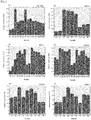
- FIGs. 1 (a) to (f) show the Vickers hardnesses for cast materials and quenched materials of samples (1) to (10) and (14) to (18).
- samples (4) to (6), (8), (9), and (15) to (18) which were iron-based alloys of embodiments of the present invention, had high hardness as they were evidenced to have a Vickers hardness of HV 250 or more even though they were cast materials before quenching (As Cast). Further, as shown in FIG.
- samples (15) to (18) having a portion of Cu replaced with Ni were highly hardened as they were evidenced to have an HV of 500 or more by quenching after heat treatment at 900°C to 1000°C.
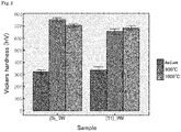
- FIG. 2 shows the Vickers hardnesses for cast materials and quenched materials subjected to heat treatment at 900°C or 1000°C of the sample (5) in which the addition amount of W was 3 mass% and the sample (11) in which the addition amount of W was 9 mass%.
- the sample (11) had high hardness as it was evidenced to have an HV 600 or more although it had lower hardness after quenching as compared with sample (5).
- FIG. 3 shows the time-dependent change of the weight loss with respect to the immersion time in the corrosion-resistance evaluation tests for cast materials of the samples (1) to (9).
- samples (3) and (7) in which the addition amount of Cr was 4 mass%, had larger weight loss, indicating inferior corrosion resistance.
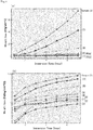
- FIG. 4 (a) shows the Vickers hardnesses for cast materials and quenched materials subjected to heat treatment at 900°C or 1000°C of samples (3) to (6), in which the addition amount of Cr was varied from 4 mass% to 20 mass%.
- FIGs. 4 (b) and (c) show the time-dependent change of the weight loss with respect to the immersion time in the corrosion-resistance evaluation tests for cast materials. Further, the corrosion rate of each sample was obtained from FIGs. 4 (b) and (c) using the following equation, and plotted against the addition amount of Cr, the results of which are shown in FIG. 4 (d) .
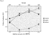
- FIG. 5 shows the Vickers hardnesses for cast materials and quenched materials subjected to heat treatment at 900°C or 1000°C of samples (5) and (22) to (24), in which the addition amount of C was varied from 0.5 mass% to 2.0 mass%. As shown in FIG. 5 , all of the samples showed HV 500 or more after quenching, indicating that high hardness was obtained.
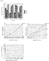
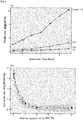
- FIG. 6 (a) shows that the time-dependent change of the weight loss with respect to the immersion time in the corrosion-resistance evaluation tests for cast materials of samples (5), (13), (20), and (21), in which the addition amount of Cu was varied from 0 mass% to 5 mass%.
- the corrosion rate of each sample was obtained from FIG. 6 (a) , and plotted against the addition amount of Cu, the results of which are shown in Fig. 6 (b) .
- the corrosion rate was significantly decreased by adding even a small amount of Cu to the sample (13) having no Cu added, while corrosion resistance did not significantly change when the addition amount of Cu was increased to 1 mass% or more.
- the addition amount of Cu is preferably 0.5 mass% or more.
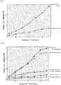
- FIG. 7 shows the time-dependent change of the weight loss with respect to the immersion time in the corrosion-resistance evaluation tests for a cast material and a quenched material subjected to heat treatment at 900°C of the sample (4). As shown in FIG. 7 , corrosion resistance was slightly decreased, but the value of weight loss was small. These results suggest that the sample (4) gains significantly high hardness while maintaining excellent corrosion resistance (refer to FIG. 1 ).
- FIG. 8 shows the time-dependent change of the weight loss with respect to the immersion time in the corrosion-resistance evaluation tests for cast materials and/or quenched materials subjected to heat treatment at 1000°C of samples (15) to (18) in which Ni was added and the addition amount of Cu was varied in sample (5).
- corrosion resistance was increased as the addition amount of Cu increased.
- the quenched materials had slightly decreased corrosion resistance as compared with the cast materials, but the values of weight loss were small.
- FIG. 9 shows the XRD patterns of a cast material and a quenched material subjected to heat treatment at 900°C of sample (5).
- an austenite having a face-centered cubic structure was observed in the cast material, while peaks from a martensite having a body-centered cubic structure and carbides were mainly observed in the quenched material.
- Diffraction peaks after quenching are broad, suggesting that there are many lattice defects inside the crystal structure. This presumably indicates that martensitic transformation has occurred.
- FIG. 10 shows the SEM observation results (backscattered electron images) of a cast material and a quenched material subjected to heat treatment at 1000°C of sample (17).
- FIG. 11 shows results from EPMA analysis on additive element in the quenched material.
- precipitates shown in bright contrast were observed in addition to the matrix for both the cast material and the quenched material.
- Cr, W, and C were enriched in the precipitates shown in bright contrast in the backscattered electron images (SEM), indicating that these precipitates were carbides.
- preferential distribution of Cu and Ni in the matrix is considered to be responsible for improved corrosion resistance.
- thermodynamic calculation software "Thermo-Calc (available from Thermo-Calc Software: ver. 2017a, database: TCFE9: Steels/Fe-Alloys ver. 9.0" was used to investigate a heat treatment temperature for quenching the iron-based alloy according to an embodiment of the present invention and composition ranges of Cr and W.
- FIGs 12 to 14 show calculated phase diagrams thereof.
- dark gray represents ranges where austenite is stably present. It is noted that Cu and Ni have small impact on the compositions/temperature ranges where austenite is stable.
- the ranges where austenite was stable for the Fe- x Cr-3W-1C-based alloys were as follows: the heat treatment temperature was 800°C to 1250°C, and the addition amount of Cr ranged from 5 mass% to 20 mass%. Further, as shown in FIG. 13 , the ranges where austenite was stable for the Fe- x Cr-3W-2Cu-1C-based alloys were as follows: the heat treatment temperature was 800°C to 1250°C, and the addition amount of Cr ranged 5 mass% to 22 mass%.
- corrosion resistance needs to be considered when the addition amount of Cr is selected (for example, refer to Fig. 4 ).
- the ranges where austenite was stable for the Fe-16Cr- x W-1C-based alloys were as follows: the heat treatment temperature was 800°C to 1250°C, and the addition amount of W ranged 12 mass% or less.
- Samples were cut out from the material obtained after cooling in the furnace (hereinafter referred to as an "ST material"), and each subjected to heat treatment under 4 conditions of 950°C, 1000°C, 1050°C, or 1100°C with a holding time of 30 minutes to 4 hours, and then forcedly air-cooled.
- the resulting samples were each measured for a 10-point Rockwell hardness (HRC), and the mean value and the standard deviation were obtained.
- HRC Rockwell hardness
- the values of Rockwell hardness for the samples subjected to heat treatment for 2 hours are shown in Table 2.
- Table 2 the ST materials of the Fe-13Cr-3W-1C-2Cu alloy and the Fe-16Cr-3W-1C-2Cu alloy showed low values of HRC 28.0 (HV 286 in terms of Vickers hardness) and HRC 21.5 (HV 243 in terms of Vickers hardness), respectively, while the samples subjected to heat treatment at 950°C to 1100°C gained high hardness of HRC 50 or more (about HV 513 in terms of Vickers hardness). It was also observed that the sample subjected to heat treatment at 1050°C gained hardness of more than HRC 60 (HV 697 in terms of Vickers hardness) regardless of the compositions.
- Table 3 The values of Rockwell hardness for each of the samples subjected to heat treatment at 1050°C for 30 minutes to 4 hours are shown in Table 3. As shown in Table 3, hardness after forced air cooling hardly changed with the alloy composition, and a value of about 60 HRC was obtained. Table 3 also shows the Rockwell hardnesses of the samples which were subjected to heat treatment at 1050°C for 1 hour followed by forced air cooling, and then subjected to tempering heat treatment at 170°C for 2 hours. Tempering conditions were selected with reference to JIS (Japanese Industrial Standards). As shown in Table 3, no large decrease in hardness was observed after tempering either, indicating that high hardness was able to be maintained. Table 3 Composition Temp. Holding Time Cooling Method Tempering Temp.
- Test samples were manufactured as follows. First, 30-kg ingots of an Fe-13Cr-3W-1C-2Cu alloy (unit: mass%) and an Fe-16Cr-3W-1C-2Cu alloy (unit: mass%) were ingoted in a heating furnace. Each of the ingots was subjected to homogenization heat treatment at 1200°C for 4 hours and then subjected to hot forging twice at 900°C to 1200°C to produce a 50-mm square forged material. The forged material was subjected to hot rolling at 1150°C for 1 hour to produce a round bar material having a diameter of 30 mm. The round bar material was maintained at 850°C for 2 hours, and then cooled in the furnace.
- Cylindrical test pieces each having a diameter of 10 mm were cut out from the materials after cooling in the furnace, and each was sealed into a quartz tube, and then subjected to heat treatment under 4 conditions of 800°C, 900°C, 1000°C, or 1100°C for a holding time of 1 hour in a muffle furnace, and then quenched in iced water to obtain test pieces.
- Compositions of the test samples manufactured are shown in Table 4.
- Table 4 Sample Fe Cr W Cu C S O N 13Cr Bal. 12.98 2.94 1.97 0.98 0.003 0.0038 0.0052 16Cr Bal. 15.88 2.97 1.95 0.99 0.003 0.0024 0.0064 Values are expressed in the unit of mass%
- Vickers hardness was measured with an "HMV” available from Shimadzu Corporation under the following conditions: a load of 9.81 N (1 kg) and a pressing time of 10 seconds. Structural observation was performed with a scanning electron microscope (SEM; "S-3400N” available from HITACHI) (acceleration voltage: 15 kV). For a sample to be used in SEM, a surface thereof was mirror-finished in advance using emery paper, alumina, and colloidal silica. Neutron diffraction measurements were performed with a "BL20 iMATERIA" at Japan Proton Accelerator Research Complex (J-PARC).
- J-PARC Japan Proton Accelerator Research Complex
- a neutron diffraction pattern obtained from each sample was also subjected to line profile analysis by the CMWP (Convolutional Multiple Whole Profile) method to determine the dislocation density of a matrix phase comprised of a martensite or ferrite having a body-center cubic (BCC) structure, or composed of the both. It is noted that the dislocation density can also be obtained from the results of the observation of dislocation structures using X-ray diffraction including synchrotron radiation or (scanning) transmission electron microscopy. Other than the CMWP method, different approaches such as the modified Williamson-Hall/Warren-Averbach method and the like can also be used as the method of line profile analysis.
- CMWP Convolutional Multiple Whole Profile
- each sample was immersed into a 0.5 mol/L aqueous solution of sulfuric acid at room temperature, and the corrosion resistance (anti-sulfuric acid corrosion) of each sample was then evaluated based on the weight loss after a holding time of up to 7 hours.
- a sample piece to be immersed into an aqueous solution of sulfuric acid which had a diameter of 10 mm and a thickness of 2 mm, was subjected to surface polishing in advance with emery paper up to #3000.
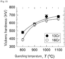
- FIG. 15 shows the relationship between heat treatment temperatures for quenching the samples of 13Cr and 16Cr (quenching temperature) respectively, and Vickers hardness.
- hardness increased as the quenching temperature increased for all of the samples. Specifically, hardness was HV 500 or more when the quenching temperature was about 850°C or more, and HV 600 or more when the quenching temperature was 950°C or more. Further, higher hardness was obtained for the samples of 13Cr as compared with the samples of 16Cr.
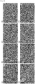
- FIGs. 16 (a) to (h) show SEM observation results (reflection electron images) of the samples of 13Cr and 16Cr, respectively.
- M 23 C 6 -type carbides were present (corresponding to bright regions in each figure).
- these carbides those having a size of several micrometers were thought to be formed by eutectic reactions upon dissolution.
- the amount of formed carbides tended to decrease as the quenching temperature increased. This is because the amount of solid solution C in an austenite stable at a high temperature side increases as the temperature increases.
- hardness was highest although the amount of carbides was clearly decreased for the samples of both 13Cr and 16Cr subjected to a quenching temperature of 1100°C as compared with other samples (refer to FIG. 15 ). This suggest that hardness of each sample is important not only for the amount or size of formed carbides but also for the hardness of a matrix.
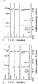
- FIGs. 17 (a) to (b) show neutron diffraction patterns obtained from neutron diffraction measurements on the samples of 13Cr and 16Cr, respectively.
- both 13Cr and 16Cr subjected to a quenching temperature of 800°C to 1000°C showed diffraction peaks from a martensite or a ferrite having a BCC structure and diffraction peaks from M 23 C 6 -type-carbides.
- the phase boundary of austenite/ferrite is present at around 800°C, and thus the sample subjected to quenching at 800°C may include ferrite as a BCC phase.
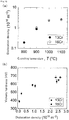
- FIG. 18 (a) shows the relationship between quenching temperature and dislocation density obtained from neutron diffraction patterns for the samples of 13Cr and 16Cr, respectively. Further, FIG. 18 (b) shows the relationship between the Vickers hardness shown in FIG. 15 and the dislocation density.
- the dislocation density increased as the quenching temperature increased for all of the samples. This is presumably because more C was forcedly dissolved within martensite through the dissolution of carbides, and thus larger lattice strain was generated as the quenching temperature increased, leading to increased dislocation density.
- the dislocation density of a matrix also showed good correlation with hardness. As understood from FIGs.
- hardness was HV 380 or more when the dislocation density was 0.2 ⁇ 10 16 m -2 or more, HV 500 or more when the dislocation density was 0.7 ⁇ 10 16 m -2 or more, and HV 600 or more when the dislocation density was 2.0 ⁇ 10 16 m -2 or more.
- FIGs. 19 (a) and (b) show the time-dependent change of the weight loss with respect to the immersion time in corrosion-resistance evaluation tests for the samples of 13Cr and 16Cr, respectively.
- FIGs. 19 (a) and (b) all the samples showed excellent corrosion resistance, and corrosion resistance was improved as the quenching temperature increased. This is presumably because carbides serving to promote corrosion were more dissolved in austenite during heat treatment as the quenching temperature increased, leading to a decreased amount of carbides being formed finally.
- high hardness obtained by the presence of carbides is in a trade-off relationship with high hardness obtained by increased dislocation density of a matrix.
- high hardness obtained by the increased dislocation density of a matrix is preferred in view of anti-sulfuric acid corrosion as understood from FIGs. 19 (a) and (b) .
- These can be optimized by controlling structures considering restrictions of applications or manufacturing equipment.
- Test samples were manufactured as follows. First, 30-kg ingots of an Fe-13Cr-3W-1C alloy (unit: mass%) and an Fe-13Cr-3W-1C-2Cu alloy (unit: mass%) were fabricated in a heating furnace. Each of the ingots was subjected to homogenization heat treatment at 1200°C for 4 hours and then subjected to hot forging twice at 900°C to 1200°C to produce a 50-mm square forged material. The forged material was maintained at 850°C for 2 hours, and then cooling in the furnace, and subsequently subjected to hot rolling at 1180°C for 2 hours to produce a round bar material having a diameter of 30 mm. The round bar material was further maintained at 850°C for 2 hours, and then cooled in the furnace.
- test pieces were cut out from the material after cooling in the furnace, and each sealed into a quartz tube, and then subjected to heat treatment under 3 conditions of 900°C, 1000°C, or 1100°C for a holding time of 1 hour in a muffle furnace, and then quenched in iced water to obtain test pieces.
- Table 5 Sample Fe Cr W Cu C S O N Si Mn Al with Cu Bal. 12.84 2.86 1.96 0.99 0.003 0.0014 0.0058 0.20 0.37 0.025 without Cu Bal. 12.83 2.95 - 1.00 0.003 0.0013 0.0057 0.21 0.36 0.024 Values are expressed in the unit of mass%
- Corrosion-resistant evaluation tests were performed on the respective test samples shown in Table 5.
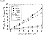
- 10 ⁇ 10 ⁇ 1 mm 3 plate-shaped test pieces were cut out from each of the test samples after quenching by wire-electrical discharge machining, and immersed into a 10 mass% aqueous solution of hydrochloric acid at room temperature, and then evaluated for corrosion resistance (anti-hydrochloric acid corrosion) based on the weight loss after a holding time of up to 7 hours.
- a sample piece to be immersed into an aqueous solution of hydrochloric acid was subjected to surface polishing in advance with emery paper up to #3000.
- FIG. 20 shows the time-dependent change of the weight loss with respect to the immersion time in corrosion-resistance evaluation tests for the samples with Cu and without Cu, respectively.
- all the samples generally had small absolute values of weight loss as compared with the results from the immersion tests in an aqueous solution of sulfuric acid as shown in FIG. 19 , and in particular, the samples with Cu showed better corrosion resistance.
- These results demonstrate that excellent corrosion resistance can be obtained not only in corrosive environments of sulfuric acid but also in corrosive environments of hydrochloric acid. Further, superior corrosion resistance tended to be achieved at a higher quenching temperature as in the results from the immersion tests in an aqueous solution of sulfuric acid shown in FIG. 19 .
Landscapes
- Chemical & Material Sciences (AREA)
- Engineering & Computer Science (AREA)
- Materials Engineering (AREA)
- Mechanical Engineering (AREA)
- Metallurgy (AREA)
- Organic Chemistry (AREA)
- Physics & Mathematics (AREA)
- Thermal Sciences (AREA)
- Crystallography & Structural Chemistry (AREA)
- Heat Treatment Of Articles (AREA)
- Heat Treatment Of Steel (AREA)
- Moulds For Moulding Plastics Or The Like (AREA)
Abstract
Description
- The present invention relates to an iron-based alloy and a method of manufacturing the iron-based alloy.
- On the resin market, super engineering plastics, which have excellent strength and thermal resistance, are expanding their markets rapidly in the automobile and electronics industries, and others. In particular, automobile manufacturers are working on trimming auto weights to achieve reduced CO2 emissions (improved fuel efficiency). To this end, they are actively promoting the replacement of steel materials, which are thought to be accountable for 60 to 70% of an auto weight. The most promising approach to this is to resinify parts. Highly-functional super engineering plastics having excellent thermal resistance or durability are also used ubiquitously in the course of "car electronization" for the purpose of improving comfort and safety.
- Super engineering plastics may include those types such as
polyamide 11 and 12 (PA11 and 12) resin, polyphenylene sulfide (PPS) resin, and fluorine resin. They are selected according to the requirements for the environments where they are used, such as strength, operating temperature, and chemical resistance. Among the super engineering plastic resins used in the automobile field, PPS resin is used most often after PA11 and PA12, and adopted for applications such ignition coil casings, headlamp reflectors, and fuel pump impellers. Further, as PPS resin is also excellent in thermal resistance/heat check resistance/chemical resistance, recently there has been increasing demand for electrical components such as sensors and ECU cases. Among the super engineering plastic resins used in the electric and electronic fields, PPS resin is also the most in demand globally due to its excellent precision moldability/fire retardancy, and is used for microswitches, optical pickups of CD drives, and others. Meanwhile, in our country, where the automobile and electronics industries are prosperous, PPS resin is more in demand than PA11 and PA12, and has been constantly ranked as the most in demand. - PPS resin has high added value and is expected to rapidly expand its global and domestic markets as described above. In the molding process of PPS resin, however, the service life of the parts of the molding machines is the greatest concern. In PPS resin, corrosive "sulfurous acid gas (SO2)" may be generated during plasticizing and melting. Therefore, equipment members need to be developed which can withstand such harsh usage environments. Serious abrasion may also occur due to a hard filler (glass fiber: GF) added for improving the strength of the parts. For this reason, a metal part which will be in contact with melted resin, such as a plasticizing apparatus for molding and a mold, may seriously suffer from corrosive wear, soon resulting in poor plasticization, poor filling, defects in shape, and the like. In recent years, these risks have become increasingly serious because the filling factor of fillers is continuing to increase.
- In order to solve the above problems, Fe-Cr based alloys (SKD11, SUS420J2, SUS440C, and others), which have relatively good corrosion resistance and can be hardened by quenching, hard chromium plating, or coatings of titanium nitride and others may be used in conventional plasticizing apparatuses for the molding of PPS resin. However, Fe-Cr based alloys such as SKD11 do not necessarily have sufficient corrosion resistance and abrasion resistance. Accordingly, the following measures are currently being taken: parts of a plasticizing apparatus may be replaced before defects occur, such as when a part is worn to a reference value or more as determined by periodical measuring of the dimensions of it; when surface roughness is visually detected; when the number of shots reaches a certain valve as determined based on operational experience; or the like. Further, surface treatments such as coating, which has an issue of peeling, are difficult to use for a long period of time.
- Accordingly, martensitic stainless steel has been proposed for use as a material of a plasticizing apparatus and a mold for resin molding in place of Fe-Cr based alloys such as SKD11 and coatings (for example, see
Patent Literature 1 to 3). -
- Patent Literature 1:
Japanese Patent No. 4952888 - Patent Literature 2:
Japanese Translation of PCT International Application Publication No. 2017-512253 - Patent Literature 3:
Japanese Patent Application Laid-Open No. 2017-166066 - However, while the martensitic stainless steels according to
Patent Literature 1 to 3 can provide either corrosion resistance capable of withstanding corrosion due to sulfurous acid gas generated upon the melting of PPS resin or high strength (abrasion resistance) capable of withstanding abrasive wear due to a hard filler (glass fiber: GF), they cannot provide both simultaneously. - The present invention was made in view of the above problems. An object of the present invention is to provide an iron-based alloy having both excellent corrosion resistance and high strength and a method of manufacturing the iron-based alloy.
- To achieve the above object, an iron-based alloy according to the present invention may include Cr: 10 to 22 mass%, W: 1 to 12 mass%, and C: 0.1 to 2.3 mass%, with the remainder being unavoidable impurities and Fe.
- The method for manufacturing an iron-based alloy according the present invention may comprise casting a composition of raw materials including Cr: 10 to 22 mass%, W: 1 to 12 mass%, and C: 0.1 to 2.3 mass%, with the remainder being unavoidable impurities and Fe. Further, in the method for manufacturing an iron-based alloy according to the present invention, an iron-based alloy having a structure composed mainly of martensite and in which M23C6-type carbides are precipitated, is preferably manufactured by heat-treatment at 600°C to 1250°C for 0.5 to 24 hours and subsequent rapid cooling of a material prepared by casting or a material processed after casting the composition of raw materials.
- The iron-based alloy according to the present invention can be suitably manufactured by the method for manufacturing an iron-based alloy according to the present invention. In the method for manufacturing an iron-based alloy according to the present invention, the iron-based alloy according to the present invention can be manufactured to be composed of cast material by casting the composition of raw materials. As the addition amount of Cr is 10 mass% to 22 mass%, the addition amount of W is 1 mass% to 12 mass%, and the addition amount of C is 0.1 mass% to 2.3 mass% in the resulting cast material, a high-temperature range can be achieved where an austenite having a face-centered cubic structure is stabilized. Therefore, martensitic transformation can be induced by maintaining that high-temperature range and then quenching in iced water and the like so that quenching forms a high-hardness martensitic structure comprised of a matrix mainly having a body-centered cubic structure, and further to form carbides of the M23C6 type and the like. Martensitic transformation can also be induced during cooling by using a water-cooling mold as in the arc melting method and using a fast cooling rate in casting to form a high-hardness martensitic structure and carbides of the M23C6 type and the like. Thereby, the iron-based alloy according to the present invention, which has a structure composed mainly of martensite in which M23C6-type carbides are precipitated, can be manufactured. The use of martensitic transformation can provide a high-hardness matrix structure while the presence of carbides can further enhance hardness.
- For the iron-based alloy according to the present invention, both a cast material and a quenched material have excellent corrosion resistance along with high strength. The iron-based alloy according to the present invention preferably has excellent corrosion resistance against, for example, sulfuric acid, hydrochloric acid, hydrofluoric acid, nitric acid, and the like depending on corrosive environments. For the iron-based alloy according to the present invention, a cast material preferably has a Vickers hardness of HV 250 or more. Moreover, the cast material may be composed of an austenite structure or a ferrite structure. When this is the case, plastic working and the like will be unlikely to cause cracks and such, and good workability can be obtained. Alternatively, the cast material may be composed of a martensitic structure. When this is the case, the cast material can be directly used without performing plastic working. Moreover, for the iron-based alloy according to the present invention, a quenched material may have a Vickers hardness of
HV 400 or more, or may have a dislocation density of 0.2 × 10¹⁶ m-2 or more and a Vickers hardness of HV 380 or more. For the iron-based alloy according to the present invention, a quenched material does not necessarily have a structure consisting only of martensite and carbides, but may include, for example, a trace amount of ferrite or residual austenite depending on alloy compositions or heat treatment conditions. It is noted that the iron-based alloy according to the present invention may have decreased corrosion resistance when the addition amount of Cr is less than 10 mass%. Further, the addition amount of Cr is preferably 16 mass% or more in order to obtain superior corrosion resistance. - The iron-based alloy according to the present invention may further include Cu: 0.5 to 6 mass% and/or Ni: 0.5 to 2.5 mass%. In the method for manufacturing an iron-based alloy according to the present invention, the above composition of raw materials may further include Cu: 0.5 to 6 mass% and/or Ni: 0.5 to 2.5 mass%. In this case, the presence of Cu and/or Ni can further enhance corrosion resistance.
- The iron-based alloy according to the present invention may further include at least one of Al, Mo, and Si in an amount of 1 to 3 mass%. In the method for manufacturing an iron-based alloy according to the present invention, the above composition of raw materials may further include at least one of Al, Mo, and Si in an amount of 1 to 3 mass%. In this case, the presence of Al, Mo, and/or Si can further enhance corrosion resistance and oxidation resistance.
- In the method for manufacturing an iron-based alloy according to the present invention, the heat treatment temperature may be 800°C or more and 1150°C or less. Further, the heat treatment time may be 5 hours or less or 3 hours or less. In these cases, quenching can be efficiently performed in a short time. Further, the method for manufacturing an iron-based alloy according to the present invention may comprise performing tempering after heat treatment in order to enhance toughness or hardness.
- The iron-based alloy according to the present invention can be manufactured inexpensively with common dissolving/processing equipment without using powder metallurgy technology. It can also be processed into a desired shape by hot and cold working (rolling, forging, swaging, and the like) by virtue of its excellent plastic workability. Further, working processes can eliminate solidification segregation and the like to obtain homogeneous structures/properties. Moreover, the iron-based alloy according to the present invention can be highly hardened by quenching, and thus a cast material and the like before quenching can be subjected to plastic working, machining, or the like to shape it into a desired product shape such as a screw. The iron-based alloy according to the present invention may be used for any applications where excellent corrosion resistance and high strength are required, including plasticizing apparatuses, molds, or the like, for resin molding.
- The present invention can provide an iron-based alloy having excellent corrosion resistance and high strength and a method of manufacturing the iron-based alloy.
-
-
FIG. 1 shows graphs illustrating Vickers hardnesses for: (a) cast materials (As Cast) of the samples of (1) to (9) and (14) to (18); (b) quenched materials of the samples (1) to (9) subjected to heat treatment at 800°C for 2 hours; (c) quenched materials of the samples (1) to (10) and (14) to (18) subjected to heat treatment at 900°C for 2 hours; (d) quenched materials of the samples (1) to (10) and (14) to (18) subjected to heat treatment at 1000°C for 2 hours; (e) quenched materials of the samples (1) to (9) subjected to heat treatment at 1100°C for 2 hours; and (f) quenched materials of the samples (1) to (9) subjected to heat treatment at 1150°C for 2 hours of the iron-based alloys according to embodiments of the present invention. -
FIG. 2 shows a graph illustrating Vickers hardnesses for cast materials of the samples (5) and (11), a quenched material subjected to heat treatment at 900°C for 2 hours, and a quenched material subjected to heat treatment at 1000°C for 2 hours of the iron-based alloys according to embodiments of the present invention. -
FIG. 3 shows (a) a graph illustrating the time-dependent change of the weight loss with respect to the immersion time into a 0.5 mol/L aqueous solution of sulfuric acid in the corrosion-resistance evaluation tests for cast materials of the samples (1) to (9) of the iron-based alloys according to embodiments of the present invention, and (b) a graph in which the vertical axis of (a) is expressed in a logarithmic scale. -
FIG. 4 shows (a) a graph illustrating Vickers hardnesses for cast materials, quenched materials subjected to heat treatment at 900°C for 2 hours, and quenched materials subjected to heat treatment at 1000°C for 2 hours of the samples (3) to (6) of the iron-based alloys according to embodiments of the present invention; (b) a graph illustrating the time-dependent change of the weight loss with respect to the immersion time into a 0.5 mol/L aqueous solution of sulfuric acid in the corrosion-resistance evaluation tests for the cast materials; (c) an enlarged portion of the samples (4) to (6) in the graph (b); and (d) a graph illustrating the corrosion rates against the addition amounts of Cr obtained from (b) and (c). -
FIG. 5 shows a graph illustrating Vickers hardnesses for cast materials, quenched materials subjected to heat treatment at 900°C for 2 hours, and quenched materials subjected to heat treatment at 1000°C for 2 hours of the samples (5) and (22) to (24) of the iron-based alloys according to embodiments of the present invention. -
FIG. 6 shows (a) a graph illustrating the time-dependent change of the weight loss with respect to the immersion time into a 0.5 mol/L aqueous solution of sulfuric acid in the corrosion-resistance evaluation tests for cast materials of the samples (5), (13), (20), and (21) of the iron-based alloys according to embodiments of the present invention; and (b) a graph illustrating the corrosion rates against the addition amounts of Cu obtained from (a). -
FIG. 7 shows a graph illustrating the time-dependent change of the weight loss with respect to the immersion time into a 0.5 mol/L aqueous solution of sulfuric acid in the corrosion-resistance evaluation tests for a cast material and a quenched material subjected to heat treatment at 900°C for 2 hours of the sample (4) of the iron-based alloys according to embodiments of the present invention. -
FIG. 8 shows a graph illustrating the time-dependent change of the weight loss with respect to the immersion time into a 0.5 mol/L aqueous solution of sulfuric acid in the corrosion-resistance evaluation tests for cast materials and/or quenched materials subjected to heat treatment at 1000°C for 2 hours of the samples (5) and (15) to (18) of the iron-based alloys according to embodiments of the present invention. -
FIG. 9 shows XRD patterns of a cast material and a quenched material subjected to heat treatment at 900°C for 2 hours of the sample (5) of the iron-based alloys according to embodiments of the present invention. -
FIG. 10 shows (a) a SEM photograph (a reflection electron image) of a cast material of the sample (17) of the iron-based alloy according to an embodiment of the present invention; (b) a SEM photograph of (a) enlarged at a higher magnification; (c) a SEM photograph for a quenched material of the sample (17) subjected to heat treatment at 1000°C for 2 hours; and (d) a SEM photograph of (c) enlarged at a higher magnification. -
FIG. 11 shows (a) a SEM photograph (a reflection electron image) for a quenched material of the sample (17) subjected to heat treatment at 1000°C for 2 hours of the iron-based alloy of an embodiment of the present invention; and EPMA maps of (b) Fe, (c) Cr, (d) W, (e) C, (f) Cu, and (g) Ni. -
FIG. 12 shows a calculated phase diagram illustrating the results from thermodynamic calculations for Fe-xCr-3W-1C (unit: mass%, x=0 to 30)-based alloys as the iron-based alloys of embodiments of the present invention. -
FIG. 13 shows a calculated phase diagram illustrating the results from thermodynamic calculations for Fe-xCr-3W-2Cu-1C (unit: mass%, x=0 to 30)-based alloys as the iron-based alloys of embodiments of the present invention. -
FIG. 14 shows a calculated phase diagram illustrating the results from thermodynamic calculations for an Fe-16Cr-xW-1C (unit: mass%, x=0 to 30)-based alloy as the iron-based alloy according to an embodiment of the present invention. -
FIG. 15 shows a graph illustrating the relationship between quenching temperature and Vickers hardness for quenched materials of an Fe-13Cr-3W-1C-2Cu alloy (unit: mass%, "13Cr") and an Fe-16Cr-3W-1C-2Cu alloy (unit: mass%, "16Cr") as the iron-based alloys according to embodiments of the present invention. -
FIG. 16 shows SEM photographs (reflection electron images) of quenched materials of 13Cr shown inFIG. 15 subjected to quenching temperatures of (a) 800°C, (b) 900°C, (c) 1000°C, and (d) 1100°C; and quenched materials of 16Cr subjected to quenching temperatures of (e) 800°C, (f) 900°C, (g) 1000°C, and (h) 1100°C. -
FIG. 17 shows neutron diffraction patterns of (a) the quenched materials of 13Cr treated at the respective quenching temperatures and (b) the quenched materials of 16Cr treated at the respective quenching temperatures. -
FIG. 18 shows (a) a graph illustrating the relationship between quenching temperatures and dislocation densities for the quenched materials of 13Cr and 16Cr shown inFIG. 15 ; and (b) a graph illustrating the relationship between Vickers hardnesses and dislocation densities. -
FIG. 19 shows graphs illustrating the time-dependent change of the weight loss with respect to the immersion time into a 0.5 mol/L aqueous solution of sulfuric acid in the corrosion-resistance evaluation tests for the quenched materials of (a) 13Cr and (b) 16Cr shown inFIG. 15 . -
FIG. 20 shows a graph illustrating the time-dependent change of the weight loss with respect to the immersion time into a 10 mass% aqueous solution of hydrochloric acid in the corrosion-resistance evaluation tests for quenched materials of an Fe-13Cr-3W-1C alloy (unit: mass%) and an Fe-13Cr-3W-1C-2Cu alloy (unit: mass%) as the iron-based alloys according to embodiments of the present invention. - Below, the embodiments of the present invention will be described with reference to Examples, the appended drawings, and the like
- The iron-based alloy of an embodiment of the present invention includes Cr: 10 to 22 mass%, W: 1 to 12 mass%, and C: 0.1 to 2.3 mass%, with the remainder being unavoidable impurities and Fe. Further, the iron-based alloy according to an embodiment of the present invention may further include Cu: 0.5 to 6 mass% and/or Ni: 0.5 to 2.5 mass%. Moreover, the iron-based alloy according to an embodiment of the present invention may further include at least one of Al, Mo, and Si in an amount of 1 to 3 mass%.
- The iron-based alloy of an embodiment of the invention can be suitably manufactured by the method for manufacturing an iron-based alloy according to an embodiment of the present invention. In the method for manufacturing an iron-based alloy according to an embodiment of the invention, the iron-based alloy according to an embodiment of the invention can first be manufactured to be composed of cast material by casting a composition of raw materials so as to obtain a composition of the iron-based alloy according to the embodiment of the invention.
- As the addition amount of Cr of the cast material is 10 mass% to 22 mass%, the addition amount of W is 1 mass% to 12 mass%, and the addition amount of C is 0.1 mass% to 2.3 mass% in the iron-based alloy according to an embodiment of the invention, a high-temperature range can be achieved where an austenite having a face-centered cubic structure is stabilized. In the method for manufacturing an iron-based alloy according to an embodiment of the invention, a cast material or a material obtained by processing the cast material may be subjected to heat treatment at the high-temperature range, i.e., 600°C to 1250°C for 0.5 to 24 hours, and subsequent quenching in iced water and the like. This can induce martensitic transformation to form a high-hardness martensitic structure composed of a matrix mainly having a body-centered cubic structure, and further to form carbides composed mainly of the M23C6 type. It is noted that the carbides may include those of the M6C type, the M7C3 type, the MC type, and the like. Martensitic transformation may also be induced during cooling by using a water-cooling mold as in the arc melting method and using a fast cooling rate in a casting process to form a high-hardness martensitic structure and carbides. In this way, the iron-based alloy of an embodiment of the invention can be manufactured as a quenched material having a structure composed mainly of martensite in which carbides are precipitated or a cast material. Use of martensitic transformation can provide a high-hardness matrix structure while the presence of carbides can further enhance hardness.
- For the iron-based alloy of an embodiment of the present invention, a quenched material includes carbides. Here, the carbides generally include a large amount of Cr, and thus corrosion resistance could be decreased for a matrix having a decreased concentration of Cr. Further, it would be feared that galvanic corrosion might occur between the carbides and the matrix. The iron-based alloy of an embodiment of the invention can prevent the aforementioned decreased corrosion resistance due to the formation of carbides by adding Cu or Ni. In addition, corrosion resistance or oxidation resistance can further be enhanced by adding Al, Mo, and/or Si.
- For the iron-based alloy according to an embodiment of the present invention, both a cast material and a quenched material have excellent corrosion resistance along with high strength. The iron-based alloy according to an embodiment of the present invention preferably has excellent corrosion resistance against, for example, sulfuric acid, hydrochloric acid, hydrofluoric acid, nitric acid, and the like depending on corrosive environments. For the iron-based alloy according to an embodiment of the present invention, a cast material may be composed of an austenitic structure or a ferritic structure. When this is the case, plastic working and the like will be unlikely to cause cracks and the like, and good workability can be obtained. Alternatively, the cast material may be composed of a martensitic structure. When this is the case, the cast material can be directly used without performing plastic working. For the iron-based alloy according to an embodiment of the present invention, a quenched material does not necessarily have a structure consisting only of martensite and carbides, but may include, for example, a trace amount of ferrite or residual austenite depending on alloy compositions or heat treatment conditions. In the method for manufacturing an iron-based alloy according to an embodiment of the present invention, a quenched material composed mainly of a martensitic structure may be subjected to tempering in order to enhance toughness or hardness.
- The iron-based alloy according to an embodiment of the present invention can be manufactured inexpensively with common dissolving/processing equipment without using powder metallurgy technology. It can also be processed into a desired shape by hot and cold working (rolling, forging, swaging, and the like) by virtue of its excellent plastic workability. Further, working processes can eliminate solidification segregation and the like to obtain homogeneous structures/properties. Moreover, the iron-based alloy according to an embodiment of the present invention can be highly hardened by quenching, and thus a cast material and the like before quenching can be subjected to plastic working, machining, or the like to shape it into a desired product shape such as a screw.
- The iron-based alloy according to an embodiment of the present invention may be used for any applications where excellent corrosion resistance and high strength are required, including plasticizing apparatuses, molds, or the like, for resin molding. The iron-based alloy according to an embodiment of the present invention has corrosion resistance capable of withstanding corrosion due to sulfurous acid gas generated upon melting of PPS resin, and high hardness (abrasion resistance) capable of withstanding abrasive wear due to a hard filler (GF), for example, when used in a plasticizing apparatus for molding PPS resin.
- Below, a cast material and a quenched material of the iron-based alloy according to an embodiment of the present invention were manufactured, and subjected to measurement of hardness, corrosion-resistance evaluation tests, structural observation, measurement of dislocation density, and the like. Further, thermodynamic calculations were performed for the iron-based alloys according to embodiments of the present invention to study heat treatment temperatures for quenching and composition ranges.
- Ingots (cast materials) of the samples (1) to (18) and (20) to (24) having the alloy compositions shown in Table 1 were fabricated with an arc melting furnace and a water-cooled copper mold. The weight of each ingot was about 100 g. Further, some of each ingot was heat treated in a muffle furnace in the atmosphere at a temperature range of 800 to 1150°C for 2 hours, and then quenched in iced water to manufacture a quenched material of each sample. It is noted that the iron-based alloys according to embodiments of the invention correspond to the samples (4) to (6), (8) to (11), (15) to (18), and (20) to (24).
Table 1 Sample No. Fe Cr W C Cu Ni Al Mo Si (1) Bal. 4 3 - - - - - - (2) Bal. 4 3 - 2 - - - - (3) Bal. 4 3 1 2 - - - - (4) Bal. 13 3 1 2 - - - - (5) Bal. 16 3 1 2 - - - - (6) Bal. 20 3 1 2 - - - - (7) Bal. 4 3 1 2 - 2 2 - (8) Bal. 16 3 1 2 - 2 2 - (9) Bal. 16 3 1 2 - 2 2 2 (10) Bal. 13 3 1 - - - - - (11) Bal. 16 9 1 2 - - - - (12) Bal. 16 3 - - - - - - (13) Bal. 16 3 1 - - - - - (14) Bal. 16 - - - - - - - (15) Bal. 16 3 1 0.5 1 - - - (16) Bal. 16 3 1 0.5 2 - - - (17) Bal. 16 3 1 1 2 - - - (18) Bal. 16 3 1 2 2 - - - (20) Bal. 16 3 1 5 - - - - (21) Bal. 16 3 1 1 - - - - (22) Bal. 16 3 0.5 2 - - - - (23) Bal. 16 3 1.5 2 - - - - (24) Bal. 16 3 2 2 - - - - - A cast material and a quenched material of each sample were subjected to measurement of Vickers hardness, corrosion-resistance evaluation tests, and structural observation. Vickers hardness was measured with an "HMV" available from Shimadzu Corporation under the following conditions: a load of 9.81 N (1 kg) and a pressing time of 10 seconds. For corrosion-resistance evaluation tests, each sample was immersed into a 0.5 mol/L aqueous solution of sulfuric acid at room temperature, which simulated corrosion due to sulfurous acid gas, and the corrosion resistance (anti-sulfuric acid corrosion) of each sample was then evaluated based on the weight loss after a holding time of 1 to 7 hours. A sample piece to be immersed into an aqueous solution of sulfuric acid was subjected to surface polishing in advance with emery paper up to #3000.
- The following method and equipment were used to evaluate structures.
- X ray diffraction (XRD) measurement: an "X'Pert MPD" available from PANalytical.
- Scanning electron microscope (SEM) observation: an "S-3400N" available from HITACHI (acceleration voltage: 15 kV).
- Analysis with a field-emission electron probe micro analyzer (EPMA): a "JXA-8530F" available from JEOL (acceleration voltage: 15 kV).
- Scanning transmission electron microscope (STEM) observation: a "Titan3 60-300 Probe Corrector" available from FEI (acceleration voltage: 300 kV).
- For a sample to be used in XRD and EPMA, a surface to be analyzed was mirror-finished in advance using emery paper, alumina, and colloidal silica. A sample for TEM observation was prepared using a focused ion beam (FIB) instrument (a "Versa 3D Dual Beam" available from FEI).
-
FIGs. 1 (a) to (f) show the Vickers hardnesses for cast materials and quenched materials of samples (1) to (10) and (14) to (18). As shown inFIG. 1 (a) , samples (4) to (6), (8), (9), and (15) to (18), which were iron-based alloys of embodiments of the present invention, had high hardness as they were evidenced to have a Vickers hardness of HV 250 or more even though they were cast materials before quenching (As Cast). Further, as shown inFIG. 1 (a) to (f ), samples (4) to (6), (8), (9), and (15) to (18), which were iron-based alloys according to embodiments of the invention, were highly hardened by quenching although the optimal temperatures for heat treatment were different depending on the compositions. In particular, samples (8) and (9), to which Al, Mo, and also Si were added with the expectation of improved corrosion resistance and oxidation resistance, were highly hardened as they were evidenced to have a Vickers hardness of aboutHV 400 by selecting an appropriate temperature (1150°C). Further, samples (15) to (18) having a portion of Cu replaced with Ni were highly hardened as they were evidenced to have an HV of 500 or more by quenching after heat treatment at 900°C to 1000°C. -
FIG. 2 shows the Vickers hardnesses for cast materials and quenched materials subjected to heat treatment at 900°C or 1000°C of the sample (5) in which the addition amount of W was 3 mass% and the sample (11) in which the addition amount of W was 9 mass%. As shown inFIG. 2 , the sample (11) had high hardness as it was evidenced to have anHV 600 or more although it had lower hardness after quenching as compared with sample (5). -
FIG. 3 shows the time-dependent change of the weight loss with respect to the immersion time in the corrosion-resistance evaluation tests for cast materials of the samples (1) to (9). As shown inFIG. 3 , samples (3) and (7), in which the addition amount of Cr was 4 mass%, had larger weight loss, indicating inferior corrosion resistance. These results suggest that even a Cu-containing alloy cannot gain high corrosion resistance if the addition amount of Cr is less than 10 mass%. It is noted that samples (1) and (2), in which the addition amount of Cr was 4 mass%, showed good corrosion resistance, but had lower hardness as shown inFIG. 1 (a) because C was not added. -
FIG. 4 (a) shows the Vickers hardnesses for cast materials and quenched materials subjected to heat treatment at 900°C or 1000°C of samples (3) to (6), in which the addition amount of Cr was varied from 4 mass% to 20 mass%.FIGs. 4 (b) and (c) show the time-dependent change of the weight loss with respect to the immersion time in the corrosion-resistance evaluation tests for cast materials. Further, the corrosion rate of each sample was obtained fromFIGs. 4 (b) and (c) using the following equation, and plotted against the addition amount of Cr, the results of which are shown inFIG. 4 (d) .
- As shown in
FIG. 4 (a) , Vickers hardness does not significantly change as a function of the addition amount of Cr. Nonetheless, excellent corrosion resistance was obtained when the addition amount of Cr was 10 mass% or more, as shown inFIGs. 4 (b) to (d) . As shown inFIG. 4 (c) , sample (5), in which the addition amount of Cr was 16 mass%, had superior corrosion resistance as compared with sample (4), in which the addition amount of Cr was 13 mass%; but corrosion resistance did not significantly change even when the addition amount of Cr was further increased. These results suggest that the addition amount of Cr is preferably 10 mass% or more, and more preferably 16 mass% or more in order to obtain excellent corrosion resistance. -
FIG. 5 shows the Vickers hardnesses for cast materials and quenched materials subjected to heat treatment at 900°C or 1000°C of samples (5) and (22) to (24), in which the addition amount of C was varied from 0.5 mass% to 2.0 mass%. As shown inFIG. 5 , all of the samples showedHV 500 or more after quenching, indicating that high hardness was obtained. -
FIG. 6 (a) shows that the time-dependent change of the weight loss with respect to the immersion time in the corrosion-resistance evaluation tests for cast materials of samples (5), (13), (20), and (21), in which the addition amount of Cu was varied from 0 mass% to 5 mass%. Further, as inFIG. 4 (d) , the corrosion rate of each sample was obtained fromFIG. 6 (a) , and plotted against the addition amount of Cu, the results of which are shown inFig. 6 (b) . As shown inFIGs. 6 (a) and (b) , the corrosion rate was significantly decreased by adding even a small amount of Cu to the sample (13) having no Cu added, while corrosion resistance did not significantly change when the addition amount of Cu was increased to 1 mass% or more. These results suggest that the addition amount of Cu is preferably 0.5 mass% or more. -
FIG. 7 shows the time-dependent change of the weight loss with respect to the immersion time in the corrosion-resistance evaluation tests for a cast material and a quenched material subjected to heat treatment at 900°C of the sample (4). As shown inFIG. 7 , corrosion resistance was slightly decreased, but the value of weight loss was small. These results suggest that the sample (4) gains significantly high hardness while maintaining excellent corrosion resistance (refer toFIG. 1 ). -
FIG. 8 shows the time-dependent change of the weight loss with respect to the immersion time in the corrosion-resistance evaluation tests for cast materials and/or quenched materials subjected to heat treatment at 1000°C of samples (15) to (18) in which Ni was added and the addition amount of Cu was varied in sample (5). As shown inFIG. 8 , corrosion resistance was increased as the addition amount of Cu increased. Further, the quenched materials had slightly decreased corrosion resistance as compared with the cast materials, but the values of weight loss were small. These results suggest that quenching can confer significantly high hardness on these samples while maintaining excellent corrosion resistance (refer toFIG. 1 ) . -
FIG. 9 shows the XRD patterns of a cast material and a quenched material subjected to heat treatment at 900°C of sample (5). As shown inFIG. 9 , an austenite having a face-centered cubic structure was observed in the cast material, while peaks from a martensite having a body-centered cubic structure and carbides were mainly observed in the quenched material. Diffraction peaks after quenching are broad, suggesting that there are many lattice defects inside the crystal structure. This presumably indicates that martensitic transformation has occurred. -
FIG. 10 shows the SEM observation results (backscattered electron images) of a cast material and a quenched material subjected to heat treatment at 1000°C of sample (17). Further,FIG. 11 shows results from EPMA analysis on additive element in the quenched material. As shown inFIG. 10 , precipitates shown in bright contrast were observed in addition to the matrix for both the cast material and the quenched material. Further, as shown inFIG. 11 , Cr, W, and C were enriched in the precipitates shown in bright contrast in the backscattered electron images (SEM), indicating that these precipitates were carbides. Further, preferential distribution of Cu and Ni in the matrix is considered to be responsible for improved corrosion resistance. - In order to achieve high hardness by quenching, heat treatment needs to be performed at a temperature range where austenite is stable. A temperature range and a composition rage where austenite is stable can be estimated by thermodynamic calculations. Accordingly, a thermodynamic calculation software "Thermo-Calc (available from Thermo-Calc Software: ver. 2017a, database: TCFE9: Steels/Fe-Alloys ver. 9.0" was used to investigate a heat treatment temperature for quenching the iron-based alloy according to an embodiment of the present invention and composition ranges of Cr and W.
- Thermodynamic calculations were performed on Fe-xCr-3W-1C (unit: mass%, x = 0 to 30)-based alloys, Fe-xCr-3W-2Cu-1C (unit: mass%, x = 0 to 30)-based alloys, and Fe-16Cr-xW-1C (unit: mass%, x = 0 to 30) based alloys.
FIGs 12 to 14 show calculated phase diagrams thereof. In the figures, dark gray represents ranges where austenite is stably present. It is noted that Cu and Ni have small impact on the compositions/temperature ranges where austenite is stable. - As shown in
FIG. 12 , the ranges where austenite was stable for the Fe-xCr-3W-1C-based alloys were as follows: the heat treatment temperature was 800°C to 1250°C, and the addition amount of Cr ranged from 5 mass% to 20 mass%. Further, as shown inFIG. 13 , the ranges where austenite was stable for the Fe-xCr-3W-2Cu-1C-based alloys were as follows: the heat treatment temperature was 800°C to 1250°C, and the addition amount of Cr ranged 5 mass% to 22 mass%. However, corrosion resistance needs to be considered when the addition amount of Cr is selected (for example, refer toFig. 4 ). - As shown in
FIG. 14 , the ranges where austenite was stable for the Fe-16Cr-xW-1C-based alloys were as follows: the heat treatment temperature was 800°C to 1250°C, and the addition amount of W ranged 12 mass% or less. - In view of manufacture with industrial equipment, 30-kg ingots of two types of iron-based alloys of an Fe-13Cr-3W-1C-2Cu alloy (unit: mass%) and an Fe-16Cr-3W-1C-2Cu alloy (unit: mass%) were fabricated with a high-frequency induction furnace. Each of the ingots was subjected to homogenization heat treatment at 1200°C for 4 hours, and then subjected to hot forging and hot rolling to produce a round bar material having a diameter of 30 mm. The round bar material was maintained at 850°C for 2 hours, and then cooled in the furnace. Samples were cut out from the material obtained after cooling in the furnace (hereinafter referred to as an "ST material"), and each subjected to heat treatment under 4 conditions of 950°C, 1000°C, 1050°C, or 1100°C with a holding time of 30 minutes to 4 hours, and then forcedly air-cooled. The resulting samples were each measured for a 10-point Rockwell hardness (HRC), and the mean value and the standard deviation were obtained.
- The values of Rockwell hardness for the samples subjected to heat treatment for 2 hours are shown in Table 2. As shown in Table 2, the ST materials of the Fe-13Cr-3W-1C-2Cu alloy and the Fe-16Cr-3W-1C-2Cu alloy showed low values of HRC 28.0 (HV 286 in terms of Vickers hardness) and HRC 21.5 (HV 243 in terms of Vickers hardness), respectively, while the samples subjected to heat treatment at 950°C to 1100°C gained high hardness of HRC 50 or more (about HV 513 in terms of Vickers hardness). It was also observed that the sample subjected to heat treatment at 1050°C gained hardness of more than HRC 60 (HV 697 in terms of Vickers hardness) regardless of the compositions. It was also observed that the samples subjected to heat treatment at 950°C to 1100°C showed small standard deviations, indicating that they were homogeneous materials. It is noted that high hardness was obtained in these experiments even without water quenching, and at a cooling rate as fast as that used in forced air cooling, suggesting high manufacturability with industrial equipment.
Table 2 Composition Temperature Holding Time Cooling Method Rockwell hardness (HRC) Mean Value S.D. Fe-13Cr-3W-2Cu-1 C 850° C 2 hours Cooling in furnace 28.0 2.6 Fe-16Cr-3W-2Cu-1 C 21.5 0.6 Fe-13Cr-3W-2Cu-1 C 950° C 2 hours Forced air cooling 56.8 0.6 Fe-16Cr-3W-2Cu-1 C 53.2 0.3 Fe-13Cr-3W-2Cu-1 C 1000° C 2 hours Forced air cooling 61.9 0.5 Fe-16Cr-3W-2Cu-1 C 57.9 0.5 Fe-13Cr-3W-2Cu-1 C 1050° C 2 hours Forced air cooling 62.9 0.3 Fe-16Cr-3W-2Cu-1 C 61.2 0.2 Fe-13Cr-3W-2Cu-1 C 1100° C 2 hours Forced air cooling 59.5 0.3 Fe-16Cr-3W-2Cu-1 C 59.2 0.3 - The values of Rockwell hardness for each of the samples subjected to heat treatment at 1050°C for 30 minutes to 4 hours are shown in Table 3. As shown in Table 3, hardness after forced air cooling hardly changed with the alloy composition, and a value of about 60 HRC was obtained. Table 3 also shows the Rockwell hardnesses of the samples which were subjected to heat treatment at 1050°C for 1 hour followed by forced air cooling, and then subjected to tempering heat treatment at 170°C for 2 hours. Tempering conditions were selected with reference to JIS (Japanese Industrial Standards). As shown in Table 3, no large decrease in hardness was observed after tempering either, indicating that high hardness was able to be maintained.
Table 3 Composition Temp. Holding Time Cooling Method Tempering Temp. Tempering Time Rockwell hardness (HRC) Mean Value S.D. Fe-13Cr-3W-2Cu-1C 1050° C 30 minutes Forced air cooling - - 62.6 0.8 Fe-16Cr-3W-2Cu-1C 60.0 0.4 Fe-13Cr-3W-2Cu-1C 1050° C 1 hour Forced air cooling - - 62.9 0.3 Fe-16Cr-3W-2Cu-1C 61.0 0.2 Fe-13Cr-3W-2Cu-1C 62.9 0.3 Fe-16Cr-3W-2Cu-1C 61.2 0.2 Fe-13Cr-3W-2Cu-1C 1050° C 4 hours Forced air cooling - - 61.5 0.6 Fe-16Cr-3W-2Cu-1C 59.8 1.0 Fe-13Cr-3W-2Cu-1C 1050° C 1 hour Forced air cooling 170° C 2 hours 61.1 0.3 Fe-16Cr-3W-2Cu-1C 57.9 0.3 - Test samples were manufactured as follows. First, 30-kg ingots of an Fe-13Cr-3W-1C-2Cu alloy (unit: mass%) and an Fe-16Cr-3W-1C-2Cu alloy (unit: mass%) were ingoted in a heating furnace. Each of the ingots was subjected to homogenization heat treatment at 1200°C for 4 hours and then subjected to hot forging twice at 900°C to 1200°C to produce a 50-mm square forged material. The forged material was subjected to hot rolling at 1150°C for 1 hour to produce a round bar material having a diameter of 30 mm. The round bar material was maintained at 850°C for 2 hours, and then cooled in the furnace. Cylindrical test pieces each having a diameter of 10 mm were cut out from the materials after cooling in the furnace, and each was sealed into a quartz tube, and then subjected to heat treatment under 4 conditions of 800°C, 900°C, 1000°C, or 1100°C for a holding time of 1 hour in a muffle furnace, and then quenched in iced water to obtain test pieces. Compositions of the test samples manufactured are shown in Table 4.
Table 4 Sample Fe Cr W Cu C S O N 13Cr Bal. 12.98 2.94 1.97 0.98 0.003 0.0038 0.0052 16Cr Bal. 15.88 2.97 1.95 0.99 0.003 0.0024 0.0064 - For each of the test samples shown in Table 4, measurement of Vickers hardness, structural observation, neutron diffraction measurements, measurement of dislocation density, and corrosion-resistance evaluation tests were performed. It is noted that a sample of a quenched material of the Fe-13Cr-3W-1C-2Cu alloy is referred to as "13Cr," and a sample of a quenched material of the Fe-16Cr-3W-1C-2Cu is referred to as "16Cr."
- Vickers hardness was measured with an "HMV" available from Shimadzu Corporation under the following conditions: a load of 9.81 N (1 kg) and a pressing time of 10 seconds. Structural observation was performed with a scanning electron microscope (SEM; "S-3400N" available from HITACHI) (acceleration voltage: 15 kV). For a sample to be used in SEM, a surface thereof was mirror-finished in advance using emery paper, alumina, and colloidal silica. Neutron diffraction measurements were performed with a "BL20 iMATERIA" at Japan Proton Accelerator Research Complex (J-PARC). A neutron diffraction pattern obtained from each sample was also subjected to line profile analysis by the CMWP (Convolutional Multiple Whole Profile) method to determine the dislocation density of a matrix phase comprised of a martensite or ferrite having a body-center cubic (BCC) structure, or composed of the both. It is noted that the dislocation density can also be obtained from the results of the observation of dislocation structures using X-ray diffraction including synchrotron radiation or (scanning) transmission electron microscopy. Other than the CMWP method, different approaches such as the modified Williamson-Hall/Warren-Averbach method and the like can also be used as the method of line profile analysis. For corrosion-resistance evaluation tests, each sample was immersed into a 0.5 mol/L aqueous solution of sulfuric acid at room temperature, and the corrosion resistance (anti-sulfuric acid corrosion) of each sample was then evaluated based on the weight loss after a holding time of up to 7 hours. A sample piece to be immersed into an aqueous solution of sulfuric acid, which had a diameter of 10 mm and a thickness of 2 mm, was subjected to surface polishing in advance with emery paper up to #3000.
-
FIG. 15 shows the relationship between heat treatment temperatures for quenching the samples of 13Cr and 16Cr (quenching temperature) respectively, and Vickers hardness. As shown inFIG. 15 , hardness increased as the quenching temperature increased for all of the samples. Specifically, hardness wasHV 500 or more when the quenching temperature was about 850°C or more, andHV 600 or more when the quenching temperature was 950°C or more. Further, higher hardness was obtained for the samples of 13Cr as compared with the samples of 16Cr. -
FIGs. 16 (a) to (h) show SEM observation results (reflection electron images) of the samples of 13Cr and 16Cr, respectively. As shown inFIG. 16 , M23C6-type carbides were present (corresponding to bright regions in each figure). Among these carbides, those having a size of several micrometers were thought to be formed by eutectic reactions upon dissolution. Further as shown inFIG. 16 , the amount of formed carbides tended to decrease as the quenching temperature increased. This is because the amount of solid solution C in an austenite stable at a high temperature side increases as the temperature increases. Therefore, hardness was highest although the amount of carbides was clearly decreased for the samples of both 13Cr and 16Cr subjected to a quenching temperature of 1100°C as compared with other samples (refer toFIG. 15 ). This suggest that hardness of each sample is important not only for the amount or size of formed carbides but also for the hardness of a matrix. -
FIGs. 17 (a) to (b) show neutron diffraction patterns obtained from neutron diffraction measurements on the samples of 13Cr and 16Cr, respectively. As shown inFIG. 17 , both 13Cr and 16Cr subjected to a quenching temperature of 800°C to 1000°C showed diffraction peaks from a martensite or a ferrite having a BCC structure and diffraction peaks from M23C6-type-carbides. It is noted that the phase boundary of austenite/ferrite is present at around 800°C, and thus the sample subjected to quenching at 800°C may include ferrite as a BCC phase. On the other hand, a diffraction peak from residual austenite was observed for the sample subjected to quenching from 1100°C in addition to these. In general, hardness is decreased due to formation of residual austenite. However, high hardness was able to be obtained even in the presence of residual austenite for the respective samples of 13Cr and 16Cr. It is noted that this residual austenite may be transformed into martensite by subzero treatment for further achieving high hardness. -
FIG. 18 (a) shows the relationship between quenching temperature and dislocation density obtained from neutron diffraction patterns for the samples of 13Cr and 16Cr, respectively. Further,FIG. 18 (b) shows the relationship between the Vickers hardness shown inFIG. 15 and the dislocation density. As shown inFIG. 18 (a) , the dislocation density increased as the quenching temperature increased for all of the samples. This is presumably because more C was forcedly dissolved within martensite through the dissolution of carbides, and thus larger lattice strain was generated as the quenching temperature increased, leading to increased dislocation density. As shown inFIG. 18 (b) , the dislocation density of a matrix also showed good correlation with hardness. As understood fromFIGs. 18 (a) and (b) , hardness was HV 380 or more when the dislocation density was 0.2 × 10¹⁶ m-2 or more,HV 500 or more when the dislocation density was 0.7 × 10¹⁶ m-2 or more, andHV 600 or more when the dislocation density was 2.0 × 10¹⁶ m-2 or more. -
FIGs. 19 (a) and (b) show the time-dependent change of the weight loss with respect to the immersion time in corrosion-resistance evaluation tests for the samples of 13Cr and 16Cr, respectively. As shown inFIGs. 19 (a) and (b) , all the samples showed excellent corrosion resistance, and corrosion resistance was improved as the quenching temperature increased. This is presumably because carbides serving to promote corrosion were more dissolved in austenite during heat treatment as the quenching temperature increased, leading to a decreased amount of carbides being formed finally. Considering the results shown inFIG. 16 andFIG. 18(a) , high hardness obtained by the presence of carbides is in a trade-off relationship with high hardness obtained by increased dislocation density of a matrix. However, high hardness obtained by the increased dislocation density of a matrix is preferred in view of anti-sulfuric acid corrosion as understood fromFIGs. 19 (a) and (b) . These can be optimized by controlling structures considering restrictions of applications or manufacturing equipment. - Test samples were manufactured as follows. First, 30-kg ingots of an Fe-13Cr-3W-1C alloy (unit: mass%) and an Fe-13Cr-3W-1C-2Cu alloy (unit: mass%) were fabricated in a heating furnace. Each of the ingots was subjected to homogenization heat treatment at 1200°C for 4 hours and then subjected to hot forging twice at 900°C to 1200°C to produce a 50-mm square forged material. The forged material was maintained at 850°C for 2 hours, and then cooling in the furnace, and subsequently subjected to hot rolling at 1180°C for 2 hours to produce a round bar material having a diameter of 30 mm. The round bar material was further maintained at 850°C for 2 hours, and then cooled in the furnace. Cylindrical test pieces were cut out from the material after cooling in the furnace, and each sealed into a quartz tube, and then subjected to heat treatment under 3 conditions of 900°C, 1000°C, or 1100°C for a holding time of 1 hour in a muffle furnace, and then quenched in iced water to obtain test pieces. The compositions of the test samples manufactured are shown in Table 5.
Table 5 Sample Fe Cr W Cu C S O N Si Mn Al with Cu Bal. 12.84 2.86 1.96 0.99 0.003 0.0014 0.0058 0.20 0.37 0.025 without Cu Bal. 12.83 2.95 - 1.00 0.003 0.0013 0.0057 0.21 0.36 0.024 - Corrosion-resistant evaluation tests were performed on the respective test samples shown in Table 5. For the corrosion-resistance evaluation tests, 10 × 10 × 1 mm3 plate-shaped test pieces were cut out from each of the test samples after quenching by wire-electrical discharge machining, and immersed into a 10 mass% aqueous solution of hydrochloric acid at room temperature, and then evaluated for corrosion resistance (anti-hydrochloric acid corrosion) based on the weight loss after a holding time of up to 7 hours. A sample piece to be immersed into an aqueous solution of hydrochloric acid was subjected to surface polishing in advance with emery paper up to #3000. It is noted that hereinafter, the samples from quenched materials of the Fe-13Cr-3W-1C alloy are referred to as "without Cu," and the samples from quenched materials of the Fe-13Cr-3W-1C-2Cu alloy are referred to as "with Cu."
-
FIG. 20 shows the time-dependent change of the weight loss with respect to the immersion time in corrosion-resistance evaluation tests for the samples with Cu and without Cu, respectively. As shown inFIG. 20 , all the samples generally had small absolute values of weight loss as compared with the results from the immersion tests in an aqueous solution of sulfuric acid as shown inFIG. 19 , and in particular, the samples with Cu showed better corrosion resistance. These results demonstrate that excellent corrosion resistance can be obtained not only in corrosive environments of sulfuric acid but also in corrosive environments of hydrochloric acid. Further, superior corrosion resistance tended to be achieved at a higher quenching temperature as in the results from the immersion tests in an aqueous solution of sulfuric acid shown inFIG. 19 .
Claims (14)
- An iron-based alloy comprising Cr: 10 to 22 mass%, W: 1 to 12 mass%, and C: 0.1 to 2.3 mass%, with the remainder being unavoidable impurities and Fe.
- The iron-based alloy according to claim 1, further comprising Cu: 0.5 to 6 mass% and/or Ni: 0.5 to 2.5 mass%.
- The iron-based alloy according to claim 1 or 2, further comprising at least one of Al, Mo, and Si in an amount of 1 to 3 mass%.
- The iron-based alloy according to any one of claims 1 to 3, wherein the iron-based alloy is composed of a cast material.
- The iron-based alloy according to claim 4, wherein the iron-based alloy has a Vickers hardness of HV 250 or more.
- The iron-based alloy according to any one of claims 1 to 3, wherein the iron-based alloy has a structure composed mainly of martensite in which M23C6-type carbides are precipitated.
- The iron-based alloy according to claim 6, wherein the iron-based alloy has a Vickers hardness of HV 400 or more.
- The iron-based alloy according to claim 6 or 7, wherein the iron-based alloy has a dislocation density of 0.2 × 10¹⁶ m-2 or more, and a Vickers hardness of HV 380 or more.
- The iron-based alloy according to claim 6 or 7, wherein the iron-based alloy has a dislocation density of 0.7 × 10¹⁶ m-2 or more, and a Vickers hardness of HV 500 or more.
- The iron-based alloy according to any one of claims 1 to 9 for use in a plasticizing apparatus or a mold for resin molding.
- A method of manufacturing an iron-based alloy, the method comprising casting a composition of raw materials comprising Cr: 10 to 22 mass%, W: 1 to 12 mass%, and C: 0.1 to 2.3 mass%, with the remainder being unavoidable impurities and Fe.
- The method according to claim 11 for manufacturing an iron-based alloy, wherein the composition of raw materials further comprises Cu: 0.5 to 6 mass% and/or Ni: 0.5 to 2.5 mass%.
- The method according to claim 11 or 12 for manufacturing an iron-based alloy, wherein the composition of raw materials further comprises at least one of Al, Mo, and Si in an amount of 1 to 3 mass%.
- The method according to any one of claims 11 to 13 for manufacturing an iron-based alloy, the method comprising manufacturing an iron-based alloy having a structure composed mainly of martensite in which M23C6-type carbides are precipitated by heat-treatment at 600°C to 1250°C for 0.5 to 24 hours and subsequent rapid cooling of a material prepared by casting or processed after casting the composition of raw materials.
Applications Claiming Priority (2)
| Application Number | Priority Date | Filing Date | Title |
|---|---|---|---|
| JP2018165465 | 2018-09-04 | ||
| PCT/JP2019/034481 WO2020050229A1 (en) | 2018-09-04 | 2019-09-02 | Iron-based alloy and method for producing iron-based alloy |
Publications (2)
| Publication Number | Publication Date |
|---|---|
| EP3848478A1 true EP3848478A1 (en) | 2021-07-14 |
| EP3848478A4 EP3848478A4 (en) | 2021-11-24 |
Family
ID=69722334
Family Applications (1)
| Application Number | Title | Priority Date | Filing Date |
|---|---|---|---|
| EP19857077.2A Pending EP3848478A4 (en) | 2018-09-04 | 2019-09-02 | IRON-BASED ALLOY AND PROCESS FOR PRODUCING AN IRON-BASED ALLOY |
Country Status (6)
| Country | Link |
|---|---|
| US (1) | US12215396B2 (en) |
| EP (1) | EP3848478A4 (en) |
| JP (1) | JP7430345B2 (en) |
| CN (1) | CN112639148B (en) |
| TW (1) | TWI891610B (en) |
| WO (1) | WO2020050229A1 (en) |
Families Citing this family (2)
| Publication number | Priority date | Publication date | Assignee | Title |
|---|---|---|---|---|
| EP4122627B1 (en) * | 2020-03-18 | 2025-06-25 | Sumitomo Electric Hardmetal Corp. | Composite sintered material and tool using same |
| CN118895451B (en) * | 2024-07-05 | 2026-04-10 | 散裂中子源科学中心 | Neutron diffraction peak-free high-thermal-conductivity VNI alloy plate and manufacturing method thereof |
Family Cites Families (21)
| Publication number | Priority date | Publication date | Assignee | Title |
|---|---|---|---|---|
| JPS5212612A (en) * | 1975-07-21 | 1977-01-31 | Nippon Steel Corp | Wear resistant tool steel |
| JPS563681A (en) * | 1979-06-22 | 1981-01-14 | Nippon Steel Corp | Tool having superior abrasion-resisting property |
| JPS584630B2 (en) | 1979-09-17 | 1983-01-27 | 日本電信電話株式会社 | Wire dot type printing head |
| JPS5930770B2 (en) * | 1981-01-30 | 1984-07-28 | 川崎製鉄株式会社 | Method for manufacturing heat-resistant and wear-resistant tool materials |
| JPH01272745A (en) * | 1988-04-21 | 1989-10-31 | Hitachi Metals Ltd | High-hardness steel for metal mold for plastic molding |
| SE521150C2 (en) * | 2002-02-15 | 2003-10-07 | Uddeholm Tooling Ab | Steel material containing carbides and use of this material |
| CN100432261C (en) * | 2003-06-12 | 2008-11-12 | 杰富意钢铁株式会社 | Thick steel plate and welded steel pipe having low yield ratio, high strength and high toughness, and method for producing same |
| JP2005163173A (en) * | 2003-11-14 | 2005-06-23 | Komatsu Ltd | Gear member and manufacturing method thereof |
| JP5122068B2 (en) * | 2004-04-22 | 2013-01-16 | 株式会社小松製作所 | Fe-based wear-resistant sliding material |
| EP1736563A1 (en) * | 2005-06-23 | 2006-12-27 | Sintec HTM AG | Steel alloy |
| JP4952888B2 (en) | 2006-04-07 | 2012-06-13 | 大同特殊鋼株式会社 | Martensite steel |
| JP5293596B2 (en) * | 2007-03-22 | 2013-09-18 | 日立金属株式会社 | Precipitation hardening type martensitic stainless cast steel with excellent machinability and manufacturing method thereof |
| CN100457952C (en) * | 2007-06-26 | 2009-02-04 | 郑州航空工业管理学院 | Casting high speed steel cutter and preparation method thereof |
| CN101537483B (en) * | 2009-04-28 | 2011-04-06 | 西安建筑科技大学 | Preparation method of reinforced composite wear-resistant lining board of precast framework |
| MX360332B (en) * | 2011-07-29 | 2018-10-29 | Nippon Steel & Sumitomo Metal Corp | High-strength galvanized steel sheet having superior bendability and method for producing same. |
| JP6228741B2 (en) * | 2012-03-27 | 2017-11-08 | 株式会社神戸製鋼所 | High-strength hot-dip galvanized steel sheet, high-strength alloyed hot-dip galvanized steel sheet, which has a small difference in strength between the central part and the end part in the sheet width direction and has excellent bending workability, and methods for producing these |
| WO2014132968A1 (en) * | 2013-02-26 | 2014-09-04 | 新日鐵住金株式会社 | HIGH-STRENGTH HOT-ROLLED STEEL SHEET HAVING MAXIMUM TENSILE STRENGTH OF 980 MPa OR ABOVE, AND HAVING EXCELLENT AND BAKING HARDENABILITY AND LOW-TEMPERATURE TOUGHNESS |
| US20160355909A1 (en) | 2014-02-18 | 2016-12-08 | Uddeholms Ab | Stainless steel for a plastic mould and a mould made of the stainless steel |
| JP6126182B2 (en) | 2015-09-07 | 2017-05-10 | ユニ・チャーム株式会社 | Absorbent package |
| JP6866692B2 (en) | 2016-03-11 | 2021-04-28 | 大同特殊鋼株式会社 | Mold steel and mold |
| JP2025126956A (en) * | 2024-02-20 | 2025-09-01 | 三菱電機株式会社 | Stator coil manufacturing method and stator coil manufacturing device |
-
2019
- 2019-09-02 CN CN201980057137.1A patent/CN112639148B/en active Active
- 2019-09-02 EP EP19857077.2A patent/EP3848478A4/en active Pending
- 2019-09-02 US US17/272,881 patent/US12215396B2/en active Active
- 2019-09-02 WO PCT/JP2019/034481 patent/WO2020050229A1/en not_active Ceased
- 2019-09-02 JP JP2020541215A patent/JP7430345B2/en active Active
- 2019-09-04 TW TW108131868A patent/TWI891610B/en active
Also Published As
| Publication number | Publication date |
|---|---|
| TW202018103A (en) | 2020-05-16 |
| WO2020050229A1 (en) | 2020-03-12 |
| CN112639148A (en) | 2021-04-09 |
| CN112639148B (en) | 2022-11-01 |
| EP3848478A4 (en) | 2021-11-24 |
| US20210317541A1 (en) | 2021-10-14 |
| TWI891610B (en) | 2025-08-01 |
| JP7430345B2 (en) | 2024-02-13 |
| US12215396B2 (en) | 2025-02-04 |
| JPWO2020050229A1 (en) | 2021-10-14 |
Similar Documents
| Publication | Publication Date | Title |
|---|---|---|
| KR101482473B1 (en) | Steel for carburizing, carburized steel component, and method for producing same | |
| KR101488120B1 (en) | Steel for carburizing, carburized steel component, and method for producing same | |
| KR101930979B1 (en) | Compression coil spring and method for producing same | |
| KR100514120B1 (en) | High-strength spring steel and spring steel wire | |
| US9695488B2 (en) | Steel for bolt use, bolt, and method for manufacturing bolt | |
| EP3118346B1 (en) | Nitriding method and nitrided part production method | |
| EP2796586A1 (en) | Steel for mechanical structure for cold working, and method for manufacturing same | |
| US20200240487A1 (en) | Helical compression spring and method for producing same | |
| EP2722406B1 (en) | Steel for molding die having excellent thermal conductivity, mirror polishing properties and toughness | |
| KR100968938B1 (en) | High strength spring steel and heat treated steel wire for high strength spring | |
| JP4955108B2 (en) | Method for producing high manganese spheroidal graphite cast iron | |
| CN113631746B (en) | Carburized component and method for manufacturing same | |
| WO2006059784A9 (en) | Steel and steel wire for high strength spring | |
| KR102209555B1 (en) | Hot rolled and annealed steel sheet having low strength-deviation, formed member, and manufacturing method of therefor | |
| KR20140110720A (en) | Mold steel for die casting and hot stamping having the high thermal conductivity and method thereof | |
| US12215396B2 (en) | Iron-based alloy and method of manufacturing the same | |
| CN104894479A (en) | Steel for mode | |
| KR20160041869A (en) | Mold steel for die casting and hot stamping having the high thermal conductivity and method thereof | |
| EP2551367B1 (en) | Prehardened steel for mold for plastic molding | |
| US20240033816A1 (en) | Die casting mold and method of making the same | |
| KR20100077250A (en) | High-strength spring steel and | |
| KR102822801B1 (en) | Economical Austenitic stainless steel with excellent machinability and manufacturing method thereof | |
| JP7163770B2 (en) | Rolling bearing component and manufacturing method thereof | |
| KR20210069584A (en) | Steel for mold, and mold | |
| Kocijan | Corrosion behaviour of additively manufactured metallic materials |
Legal Events
| Date | Code | Title | Description |
|---|---|---|---|
| STAA | Information on the status of an ep patent application or granted ep patent |
Free format text: STATUS: THE INTERNATIONAL PUBLICATION HAS BEEN MADE |
|
| PUAI | Public reference made under article 153(3) epc to a published international application that has entered the european phase |
Free format text: ORIGINAL CODE: 0009012 |
|
| STAA | Information on the status of an ep patent application or granted ep patent |
Free format text: STATUS: REQUEST FOR EXAMINATION WAS MADE |
|
| 17P | Request for examination filed |
Effective date: 20210302 |
|
| AK | Designated contracting states |
Kind code of ref document: A1 Designated state(s): AL AT BE BG CH CY CZ DE DK EE ES FI FR GB GR HR HU IE IS IT LI LT LU LV MC MK MT NL NO PL PT RO RS SE SI SK SM TR |
|
| A4 | Supplementary search report drawn up and despatched |
Effective date: 20211022 |
|
| RIC1 | Information provided on ipc code assigned before grant |
Ipc: C22C 38/42 20060101ALI20211018BHEP Ipc: C22C 38/34 20060101ALI20211018BHEP Ipc: C22C 38/20 20060101ALI20211018BHEP Ipc: C22C 38/06 20060101ALI20211018BHEP Ipc: C22C 37/06 20060101ALI20211018BHEP Ipc: C21D 5/00 20060101ALI20211018BHEP Ipc: C22C 38/44 20060101ALI20211018BHEP Ipc: C22C 38/22 20060101ALI20211018BHEP Ipc: C22C 37/08 20060101ALI20211018BHEP Ipc: C21D 6/00 20060101ALI20211018BHEP Ipc: C22C 38/00 20060101AFI20211018BHEP |
|
| DAV | Request for validation of the european patent (deleted) | ||
| DAX | Request for extension of the european patent (deleted) |