EP3848231A1 - Evaluation method - Google Patents
Evaluation method Download PDFInfo
- Publication number
- EP3848231A1 EP3848231A1 EP21150114.3A EP21150114A EP3848231A1 EP 3848231 A1 EP3848231 A1 EP 3848231A1 EP 21150114 A EP21150114 A EP 21150114A EP 3848231 A1 EP3848231 A1 EP 3848231A1
- Authority
- EP
- European Patent Office
- Prior art keywords
- terminal
- male
- female
- pair
- terminals
- Prior art date
- Legal status (The legal status is an assumption and is not a legal conclusion. Google has not performed a legal analysis and makes no representation as to the accuracy of the status listed.)
- Granted
Links
Images


Classifications
-
- B—PERFORMING OPERATIONS; TRANSPORTING
- B60—VEHICLES IN GENERAL
- B60L—PROPULSION OF ELECTRICALLY-PROPELLED VEHICLES; SUPPLYING ELECTRIC POWER FOR AUXILIARY EQUIPMENT OF ELECTRICALLY-PROPELLED VEHICLES; ELECTRODYNAMIC BRAKE SYSTEMS FOR VEHICLES IN GENERAL; MAGNETIC SUSPENSION OR LEVITATION FOR VEHICLES; MONITORING OPERATING VARIABLES OF ELECTRICALLY-PROPELLED VEHICLES; ELECTRIC SAFETY DEVICES FOR ELECTRICALLY-PROPELLED VEHICLES
- B60L53/00—Methods of charging batteries, specially adapted for electric vehicles; Charging stations or on-board charging equipment therefor; Exchange of energy storage elements in electric vehicles
- B60L53/10—Methods of charging batteries, specially adapted for electric vehicles; Charging stations or on-board charging equipment therefor; Exchange of energy storage elements in electric vehicles characterised by the energy transfer between the charging station and the vehicle
- B60L53/14—Conductive energy transfer
- B60L53/16—Connectors, e.g. plugs or sockets, specially adapted for charging electric vehicles
-
- G—PHYSICS
- G01—MEASURING; TESTING
- G01R—MEASURING ELECTRIC VARIABLES; MEASURING MAGNETIC VARIABLES
- G01R1/00—Details of instruments or arrangements of the types included in groups G01R5/00 - G01R13/00 and G01R31/00
- G01R1/02—General constructional details
- G01R1/04—Housings; Supporting members; Arrangements of terminals
- G01R1/0408—Test fixtures or contact fields; Connectors or connecting adaptors; Test clips; Test sockets
- G01R1/0416—Connectors, terminals
-
- G—PHYSICS
- G06—COMPUTING OR CALCULATING; COUNTING
- G06Q—INFORMATION AND COMMUNICATION TECHNOLOGY [ICT] SPECIALLY ADAPTED FOR ADMINISTRATIVE, COMMERCIAL, FINANCIAL, MANAGERIAL OR SUPERVISORY PURPOSES; SYSTEMS OR METHODS SPECIALLY ADAPTED FOR ADMINISTRATIVE, COMMERCIAL, FINANCIAL, MANAGERIAL OR SUPERVISORY PURPOSES, NOT OTHERWISE PROVIDED FOR
- G06Q10/00—Administration; Management
- G06Q10/06—Resources, workflows, human or project management; Enterprise or organisation planning; Enterprise or organisation modelling
- G06Q10/063—Operations research, analysis or management
- G06Q10/0639—Performance analysis of employees; Performance analysis of enterprise or organisation operations
- G06Q10/06393—Score-carding, benchmarking or key performance indicator [KPI] analysis
-
- B—PERFORMING OPERATIONS; TRANSPORTING
- B60—VEHICLES IN GENERAL
- B60L—PROPULSION OF ELECTRICALLY-PROPELLED VEHICLES; SUPPLYING ELECTRIC POWER FOR AUXILIARY EQUIPMENT OF ELECTRICALLY-PROPELLED VEHICLES; ELECTRODYNAMIC BRAKE SYSTEMS FOR VEHICLES IN GENERAL; MAGNETIC SUSPENSION OR LEVITATION FOR VEHICLES; MONITORING OPERATING VARIABLES OF ELECTRICALLY-PROPELLED VEHICLES; ELECTRIC SAFETY DEVICES FOR ELECTRICALLY-PROPELLED VEHICLES
- B60L53/00—Methods of charging batteries, specially adapted for electric vehicles; Charging stations or on-board charging equipment therefor; Exchange of energy storage elements in electric vehicles
- B60L53/10—Methods of charging batteries, specially adapted for electric vehicles; Charging stations or on-board charging equipment therefor; Exchange of energy storage elements in electric vehicles characterised by the energy transfer between the charging station and the vehicle
- B60L53/11—DC charging controlled by the charging station, e.g. mode 4
-
- B—PERFORMING OPERATIONS; TRANSPORTING
- B60—VEHICLES IN GENERAL
- B60L—PROPULSION OF ELECTRICALLY-PROPELLED VEHICLES; SUPPLYING ELECTRIC POWER FOR AUXILIARY EQUIPMENT OF ELECTRICALLY-PROPELLED VEHICLES; ELECTRODYNAMIC BRAKE SYSTEMS FOR VEHICLES IN GENERAL; MAGNETIC SUSPENSION OR LEVITATION FOR VEHICLES; MONITORING OPERATING VARIABLES OF ELECTRICALLY-PROPELLED VEHICLES; ELECTRIC SAFETY DEVICES FOR ELECTRICALLY-PROPELLED VEHICLES
- B60L53/00—Methods of charging batteries, specially adapted for electric vehicles; Charging stations or on-board charging equipment therefor; Exchange of energy storage elements in electric vehicles
- B60L53/30—Constructional details of charging stations
- B60L53/302—Cooling of charging equipment
-
- G—PHYSICS
- G01—MEASURING; TESTING
- G01R—MEASURING ELECTRIC VARIABLES; MEASURING MAGNETIC VARIABLES
- G01R27/00—Arrangements for measuring resistance, reactance, impedance, or electric characteristics derived therefrom
- G01R27/02—Measuring real or complex resistance, reactance, impedance, or other two-pole characteristics derived therefrom, e.g. time constant
- G01R27/20—Measuring earth resistance; Measuring contact resistance, e.g. of earth connections, e.g. plates
- G01R27/205—Measuring contact resistance of connections, e.g. of earth connections
-
- G—PHYSICS
- G01—MEASURING; TESTING
- G01R—MEASURING ELECTRIC VARIABLES; MEASURING MAGNETIC VARIABLES
- G01R31/00—Arrangements for testing electric properties; Arrangements for locating electric faults; Arrangements for electrical testing characterised by what is being tested not provided for elsewhere
- G01R31/005—Testing of electric installations on transport means
- G01R31/006—Testing of electric installations on transport means on road vehicles, e.g. automobiles or trucks
-
- G—PHYSICS
- G06—COMPUTING OR CALCULATING; COUNTING
- G06Q—INFORMATION AND COMMUNICATION TECHNOLOGY [ICT] SPECIALLY ADAPTED FOR ADMINISTRATIVE, COMMERCIAL, FINANCIAL, MANAGERIAL OR SUPERVISORY PURPOSES; SYSTEMS OR METHODS SPECIALLY ADAPTED FOR ADMINISTRATIVE, COMMERCIAL, FINANCIAL, MANAGERIAL OR SUPERVISORY PURPOSES, NOT OTHERWISE PROVIDED FOR
- G06Q50/00—Information and communication technology [ICT] specially adapted for implementation of business processes of specific business sectors, e.g. utilities or tourism
- G06Q50/06—Energy or water supply
-
- H—ELECTRICITY
- H01—ELECTRIC ELEMENTS
- H01R—ELECTRICALLY-CONDUCTIVE CONNECTIONS; STRUCTURAL ASSOCIATIONS OF A PLURALITY OF MUTUALLY-INSULATED ELECTRICAL CONNECTING ELEMENTS; COUPLING DEVICES; CURRENT COLLECTORS
- H01R13/00—Details of coupling devices of the kinds covered by groups H01R12/70 or H01R24/00 - H01R33/00
- H01R13/02—Contact members
- H01R13/10—Sockets for co-operation with pins or blades
- H01R13/11—Resilient sockets
- H01R13/111—Resilient sockets co-operating with pins having a circular transverse section
-
- H—ELECTRICITY
- H01—ELECTRIC ELEMENTS
- H01R—ELECTRICALLY-CONDUCTIVE CONNECTIONS; STRUCTURAL ASSOCIATIONS OF A PLURALITY OF MUTUALLY-INSULATED ELECTRICAL CONNECTING ELEMENTS; COUPLING DEVICES; CURRENT COLLECTORS
- H01R13/00—Details of coupling devices of the kinds covered by groups H01R12/70 or H01R24/00 - H01R33/00
- H01R13/02—Contact members
- H01R13/193—Means for increasing contact pressure at the end of engagement of coupling part, e.g. zero insertion force or no friction
-
- H—ELECTRICITY
- H01—ELECTRIC ELEMENTS
- H01B—CABLES; CONDUCTORS; INSULATORS; SELECTION OF MATERIALS FOR THEIR CONDUCTIVE, INSULATING OR DIELECTRIC PROPERTIES
- H01B7/00—Insulated conductors or cables characterised by their form
- H01B7/42—Insulated conductors or cables characterised by their form with arrangements for heat dissipation or conduction
- H01B7/421—Insulated conductors or cables characterised by their form with arrangements for heat dissipation or conduction for heat dissipation
- H01B7/423—Insulated conductors or cables characterised by their form with arrangements for heat dissipation or conduction for heat dissipation using a cooling fluid
-
- H—ELECTRICITY
- H01—ELECTRIC ELEMENTS
- H01R—ELECTRICALLY-CONDUCTIVE CONNECTIONS; STRUCTURAL ASSOCIATIONS OF A PLURALITY OF MUTUALLY-INSULATED ELECTRICAL CONNECTING ELEMENTS; COUPLING DEVICES; CURRENT COLLECTORS
- H01R2201/00—Connectors or connections adapted for particular applications
- H01R2201/20—Connectors or connections adapted for particular applications for testing or measuring purposes
Definitions
- the present disclosure relates to an evaluation method.
- the flexible piece has a facing surface facing a flexible piece adjacent to the flexible piece of interest in the circumferential direction of the cylinder, and any pair of such facing surfaces facing each other in the circumferential direction are parallel to each other.
Landscapes
- Engineering & Computer Science (AREA)
- Business, Economics & Management (AREA)
- General Physics & Mathematics (AREA)
- Physics & Mathematics (AREA)
- Human Resources & Organizations (AREA)
- Economics (AREA)
- Strategic Management (AREA)
- Power Engineering (AREA)
- Transportation (AREA)
- Mechanical Engineering (AREA)
- Educational Administration (AREA)
- Development Economics (AREA)
- Theoretical Computer Science (AREA)
- General Business, Economics & Management (AREA)
- Health & Medical Sciences (AREA)
- Marketing (AREA)
- Tourism & Hospitality (AREA)
- Entrepreneurship & Innovation (AREA)
- Primary Health Care (AREA)
- Operations Research (AREA)
- Water Supply & Treatment (AREA)
- Public Health (AREA)
- Combustion & Propulsion (AREA)
- Chemical & Material Sciences (AREA)
- Game Theory and Decision Science (AREA)
- General Health & Medical Sciences (AREA)
- Quality & Reliability (AREA)
- Electric Propulsion And Braking For Vehicles (AREA)
- Testing Of Devices, Machine Parts, Or Other Structures Thereof (AREA)
- Investigating Or Analyzing Materials Using Thermal Means (AREA)
- Connector Housings Or Holding Contact Members (AREA)
- Manufacturing Of Electrical Connectors (AREA)
- Details Of Connecting Devices For Male And Female Coupling (AREA)
- Charge And Discharge Circuits For Batteries Or The Like (AREA)
Abstract
Description
- This nonprovisional application is based on Japanese Patent Application No.
2020-003138 filed on January 10, 2020 - The present disclosure relates to an evaluation method.
- A connecting portion of a charging connector on the side of facilities and a charging inlet on the side of a vehicle generates heat due to contact resistance when a current passes therethrough. This is particularly remarkable when rapid charging is performed with a large current (for example of 400 A). Accordingly, a liquid-cooled type charging connector coolable with liquid such as water is known. For example, Japanese Patent Laying-Open No.
2019-187035 - When such a liquid-cooled charging connector as disclosed in Japanese Patent Laying-Open No.
2019-187035 - An object of the present disclosure is to provide an evaluation method capable of appropriately evaluating a charging connector in coolability.
- In order to address the above issue, an evaluation jig comprising a pair of female terminals connectable to a pair of male terminals of a charging connector may be used to evaluate the charging connector in coolability (or a degree at which temperature increases at a connecting portion of the male terminal and the female terminal).
- If the contact resistance between the male terminal and the female terminal when an evaluation is made varies whenever the evaluation is made, the evaluation provides an unreliable result. Therefore, it is desirable that coolability be evaluated while the contact resistance falls within a prescribed range. The present disclosure has been made based on the above point of view.
- According to one aspect of the present disclosure, an evaluation method is an evaluation method for evaluating a charging connector in coolability by connecting an evaluation jig to the charging connector, the charging connector including a pair of male terminals coolable with a coolant, the evaluation jig including a pair of female terminals connectable to the pair of male terminals, the pair of female terminals being connected to the pair of male terminals in evaluating the charging connector in coolability, the method comprising: connecting the pair of female terminals to the pair of male terminals; adjusting a connection state between the male terminal and the female terminal such that contact resistance between the male terminal and the female terminal is 0.06 mΩ or more and 0.15 mΩ or less; and after the adjusting the connection state, evaluating the coolability depending on whether the male terminal and the female terminal have a temperature of 90°C or lower when a charging current of 400 A is supplied to the male terminal and the female terminal for 30 minutes.
- In the present evaluation method, contact resistance between the male terminal and the female terminal is defined to fall within a range of 0.06 mΩ or more and 0.15 mΩ or less, and variation in evaluation results is suppressed. Therefore, the charging connector's coolability can be appropriately evaluated. Further, designing the female terminal of the charging inlet such that the contact resistance is 0.06 mΩ or more and 0.15 mΩ or less allows the male terminal and the female terminal to have a temperature of 90°C or lower when a charging connector which obtains a good evaluation result in the step of evaluating is used to charge power with a charging current of 400 A supplied for 30 minutes.
- Furthermore, in the adjusting the connection state, the connection state is preferably adjusted so that the contact resistance is 0.08 mΩ or more and 0.1 mΩ or less.
- The foregoing and other objects, features, aspects and advantages of the present invention will become more apparent from the following detailed description of the present invention when taken in conjunction with the accompanying drawings.
-
-
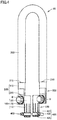
Fig. 1 is a diagram schematically showing a vehicle charged. -
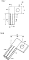
Fig. 2 is a front view of a male connector. -
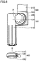
Fig. 3 is a cross section taken along a line III-III indicated inFig. 2 . -
Fig. 4 is a perspective view of an evaluation jig according to an embodiment of the present disclosure. -
Fig. 5 is a perspective view in a vicinity of a female terminal of the evaluation jig. -
Fig. 6 is a perspective view showing a relationship between the female terminal of the evaluation jig and an adjustment member. -
Fig. 7 is a plan view of the female terminal of the evaluation jig. -
Fig. 8 is a perspective view of the female terminal shown inFig. 7 . -
Fig. 9 is a perspective view of the female terminal at an angle different from that ofFig. 8 . -
Fig. 10 is an enlarged perspective view of a distal end portion of the female terminal. -
Fig. 11 is a cross section taken along a line XI-XI shown inFig. 7 . -
Fig. 12 is a cross section taken along a line XII-XII shown inFig. 7 . -
Fig. 13 is an enlarged view of a range indicated by a solid line XIII shown inFig. 12 . -
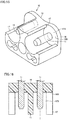
Fig. 14 is a front view of a male connector having a tubular wall partially removed. -
Fig. 15 is a perspective view of the male connector shown inFig. 14 . -
Fig. 16 is a cross section taken along a line XVI-XVI indicated inFig. 14 . -
Fig. 17 is a perspective view showing a state in which the evaluation jig has a female terminal connected to a male terminal of the male connector shown inFig. 15 . -
Fig. 18 is a cross section of the diagram shown inFig. 17 . -
Fig. 19 is a diagram schematically showing a degree at which temperature rises at each portion around a connecting portion of a male terminal and a female terminal. - An Embodiment of the present disclosure will be described with reference to the drawings. In the drawings referred to below, identical or equivalent members are identically denoted.
-
Fig. 1 is a diagram schematically showing a vehicle charged. More specifically,Fig. 1 shows a state in which acharging connector 5 connected to afacility 7 such as a charging stand via a facility-sideelectric wire 6 is connected to acharging inlet 2 of avehicle 1.Vehicle 1 is, for example, an electric vehicle. -
Charging connector 5 includes a handle (not shown) held by a user, and a male connector 10 (seeFig. 2 ) connected to the handle.Charging connector 5 is cooled by a coolant. That is,charging connector 5 is a so-called liquid-cooled charging connector. An example of the coolant includes cooling water. The coolant flows betweenfacility 7 andcharging connector 5 via facility-sideelectric wire 6. -
Male connector 10 is a portion connected to charginginlet 2 ofvehicle 1. In the present embodiment,male connector 10 is based on the ChaoJi standard. As shown inFig. 2 ,male connector 10 includes a pair ofmale terminals 11, aprotective grounding terminal 12, a pair of chargingconnection confirmation terminals 13, a pair ofcharging communication terminals 14, and amale casing 15. - Each
male terminal 11 is formed in a round column. Eachmale terminal 11 is a direct-current power supply terminal. Onemale terminal 11 is a positive electrode and the othermale terminal 11 is a negative electrode. In the present embodiment,male terminal 11 has an outer diameter of 9 mm. -
Protective grounding terminal 12 is disposed at a position spaced from a center portion between the pairedmale terminals 11 on one side in a direction orthogonal to both an imaginary line connecting the paired male terminals 11 (i.e., a lateral direction inFig. 2 ) and an axis of eachmale terminals 11, that is, in a vertical direction inFig. 2 . - Each charging
connection confirmation terminal 13 is disposed at a position spaced from onemale terminal 11 on one side in the orthogonal direction. - Each
charging communication terminal 14 is disposed at a position spaced from the othermale terminal 11 on one side in the orthogonal direction and also spaced from each chargingconnection confirmation terminal 13 in a direction parallel to the imaginary line connecting the pairedmale terminals 11. -
Male casing 15 holdsterminals 11 to 14.Male casing 15 is made of resin.Male casing 15 has abottom wall 16 and atubular wall 17. - As shown in
Fig. 3 ,bottom wall 16 holdsterminals 11 to 14 in a state in whichterminals 11 to 14 are inserted therethrough.Bottom wall 16 is formed in a flat plate.Fig. 3 shows a part offemale connector 20 of charginginlet 2. -
Tubular wall 17 surroundsmale terminal 11.Tubular wall 17 erects from a portion ofbottom wall 16 aroundmale terminal 11.Tubular wall 17 has a cylindrical inner peripheral surface.Female connector 20 of charginginlet 2 is inserted into a space between the inner peripheral surface and an outer peripheral surface ofmale terminal 11. As shown inFig. 3 ,tubular wall 17 has an inner diameter set to 23 mm. - Charging
inlet 2 is provided on an external surface ofvehicle 1. Charginginlet 2 includesfemale connector 20.Female connector 20 has a pair offemale terminals 21 and afemale casing 25. - Each
female terminal 21 is connectable tomale terminal 11. As shown inFig. 3 , eachfemale terminal 21 has a shape capable of receivingmale terminal 11. -
Female casing 25 holdsfemale terminals 21.Female casing 25 is made of resin. As shown inFig. 3 ,female casing 25 has a facingportion 26 and atubular portion 27. - Facing
portion 26 is a portion facingtubular wall 17 in a direction parallel to the axial direction of male terminal 11 (i.e., a vertical direction inFig. 3 ). Facingportion 26 has asurface 26S formed flat. As shown inFig. 3 , a distance betweensurface 26S of facingportion 26 and asurface 16S ofbottom wall 16 in the direction parallel to the axial direction ofmale terminal 11 is set to 40 mm. -
Tubular portion 27 is formed to have a cylindrical shape surroundingfemale terminal 21.Tubular portion 27 is connected to facingportion 26 in a posture such thattubular portion 27 has its center axis orthogonal to facingportion 26.Tubular portion 27 has an outer diameter smaller than the inner diameter oftubular wall 17. In a state with chargingconnector 5 connected to charginginlet 2,tubular portion 27 has adistal end portion 27a in contact withsurface 16S ofbottom wall 16. As shown inFig. 3 ,distal end portion 27a has a length set to 6 mm in a direction parallel to the axial direction oftubular portion 27. - Hereinafter,
evaluation jig 50 will be described with reference toFigs. 4 to 13 .Evaluation jig 50 is a jig capable of evaluating chargingconnector 5 in coolability (or amount of heat generated at a connecting portion ofmale terminal 11 and the female terminal). As shown inFig. 4 ,evaluation jig 50 includes a pair offemale terminals 100, anelectric wire 200, a pair ofcrimp terminals 300, and a pair ofadjustment members 400. - Each
female terminal 100 is a terminal connected tomale terminal 11. Eachfemale terminal 100 includes a plurality of (eight in the present embodiment)contact pieces 110, asupport portion 120, and a female-side flange 130. - Each
contact piece 110 is a portion that can contactmale terminal 11. The plurality ofcontact pieces 110 are disposed about and spaced from a center axis A (seeFigs. 11 to 13 ). Specifically, the plurality ofcontact pieces 110 are disposed about and equally spaced from center axisA. Contact pieces 110 are preferably set in number to 3 or more and 8 or less, particularly preferably 8. Eachcontact piece 110 has aflexible piece 112 and acontact portion 114. -
Flexible piece 112 has a shape extending in a direction parallel to center axis A.Flexible piece 112 forms a portion of a cylinder having center axis A. In other words, in the cross sections shown inFigs. 12 and13 ,flexible piece 112 has an outer peripheral surface in the form of an arc. Aslit 112S is provided between any pair offlexible pieces 112 adjacent in the circumferential direction of the cylinder. - In the direction parallel to center axis A,
flexible piece 112 has a length L1 (seeFig. 7 ) set to be equal to or larger than twice the outer diameter of the cylinder. In the present embodiment, the cylinder has an outer diameter ϕ2 (seeFig. 11 ) of 17 mm, andflexible piece 112 has length L1 of 35 mm. The cylinder has an inner diameter ϕ1 (seeFig. 11 ) of 13 mm. That is,flexible piece 112 has a thickness of 2 mm. -
Flexible piece 112 is elastically deformable such thatflexible piece 112 has adistal end portion 112a displaced in the radial direction of the cylinder relative to a proximal end portion offlexible piece 112, which is a connecting portion offlexible piece 112 andsupport portion 120. That is, the plurality of contact pieces 110 (the cylinder) can be reduced in diameter. - As shown in
Figs. 12 and13 ,flexible piece 112 has a facingsurface 112b facingflexible piece 112 adjacent toflexible piece 112 of interest in the circumferential direction of the cylinder. Any pair of facingsurfaces 112b facing each other in the circumferential direction are parallel to each other. The paired facingsurfaces 112b are spaced by 1 mm. -
Contact portion 114 has a shape protruding from the inner surface offlexible piece 112 toward center axisA. Contact portion 114 is connected to the inner surface offlexible piece 112 at a portion away fromdistal end portion 112a in the direction parallel to center axis A. That is,distal end portion 112a offlexible piece 112 configures a protruding portion protruding fromcontact portion 114 in the direction parallel to center axis A away from support portion 120 (or downward inFig. 11 ). -
Contact portion 114 has a shape curved so as to protrude inward in the radial direction. As shown inFig. 13 ,flexible piece 112 andcontact portion 114 have aboundary portion 113 therebetween in a curve.Contact portion 114 has an apex 114c with a curvature smaller than that ofboundary portion 113. In the present embodiment, apex 114c has a radius of curvature of 1 mm.Boundary portion 113 has a radius of curvature for example of 0.5 mm. - As shown in
Fig. 13 , a straight line connecting aspecific apex 114c and center axis A and a straight line connecting an apex 114c adjacent to thespecific apex 114c and center axis A form an angle of 45 degrees. A tangent to an end on one side ofcontact portion 114 in the circumferential direction and a tangent to an end on the other side ofcontact portion 114 in the circumferential direction form an angle of 30 degrees. -
Contact portion 114 has a shape extending in the direction parallel to center axis A. As shown inFigs. 10 and11 ,contact portion 114 has acontact edge portion 114a and a connectingportion 114b. -
Contact portion 114 has a shape extending in the direction parallel to center axis A.Contact edge portion 114a has a length L3 of 4.7 mm. - Connecting
portion 114b connectscontact edge portion 114a and an inner surface offlexible piece 112. Connectingportion 114b has a shape inclined so as to gradually approach the inner surface offlexible piece 112 as connectingportion 114b is farther away fromcontact edge portion 114a in the direction parallel to center axisA. Connecting portion 114b and the inner surface offlexible piece 112 have a boundary portion therebetween with a radius of curvature of 0.5 mm. Connectingportion 114b andcontact edge portion 114a have a boundary portion therebetween with a radius of curvature of 1.5 mm. -
Support portion 120 supports the plurality ofcontact pieces 110. In the present embodiment,support portion 120 is formed to have a cylindrical shape having center axis A as a center.Support portion 120 has an outer peripheral surface contiguous to that of eachflexible piece 112. That is,support portion 120 has an outer diameter equal to that of the cylinder composed of the plurality offlexible pieces 112. - As shown in
Fig. 11 ,support portion 120 is equal in thickness to eachflexible piece 112. As shown inFig. 7 , in a direction along center axis A,support portion 120 has a length L2 set to be smaller than length L1 of eachflexible piece 112. Specifically,support portion 120 has length L2 of 22 mm.Support portion 120 may be formed in a round columnar shape, a rectangular columnar shape, or the like. - Female-
side flange 130 has a shape projecting from an outer peripheral surface ofsupport portion 120 outward in the radial direction ofsupport portion 120. Female-side flange 130 is formed flat. In the direction parallel to center axis A, female-side flange 130 has a length equal to that of support portion 120 (22 mm in the present embodiment). - Female-
side flange 130 is provided with aninsertion hole 130h.Insertion hole 130h has a diameter of 10.5 mm. A distance between center axis A and the center ofinsertion hole 130h is 21 mm. -
Electric wire 200 is provided to connect the pairedfemale terminals 100 to each other.Electric wire 200 is made of copper or silver.Electric wire 200 preferably has a cross-sectional area set to 70 mm2 or more and 95 mm2 or less. In the present embodiment,electric wire 200 has a cross-sectional area set to 95 mm2.Electric wire 200 has a length set to 2 m or more. The reason for this will be described with reference toFig. 19 . -
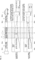
Fig. 19 represents each terminal and each electric wire in temperature whenmale terminal 11 is connected tofemale terminal 21 and a current of 400 A is supplied for 30 minutes. InFig. 19 , a region R of a connecting portion ofmale terminal 11 andfemale terminal 21 is a region which attains highest temperature. - As shown in
Fig. 19 , when a vehicle-side electric wire 3 has a cross-sectional area of 95 mm2, and whether a portion up to 100 cm frommale terminal 11 may or may not be cooled with water, it has been confirmed that a portion of vehicle-side electric wire 3 away fromfemale terminal 21 by 100 cm is stable in temperature (or an effect of heat generated at the connecting portion ofmale terminal 11 andfemale terminal 21 is substantially negligible). - Furthermore, when the portion is water-cooled, and whether vehicle-side electric wire 3 may have a cross-sectional area of 70 mm2 or 95 mm2, it has been confirmed that the portion of vehicle-side electric wire 3 away from
female terminal 21 by 100 cm is stable in temperature (or an effect of heat generated at the connecting portion ofmale terminal 11 andfemale terminal 21 is substantially negligible). - From the above results, it can be seen that, by setting
electric wire 200 to have a length of 2 m or more, an effect of heat generated at a connecting portion of onemale terminal 11 and onefemale terminal 21 on a connecting portion of the othermale terminal 11 and the otherfemale terminal 21 via the electric wire is negligible. Thus, in the present embodiment,electric wire 200 is set to have a length of 2 m or more. - Each
crimp terminal 300 is connected to anend 210 ofelectric wire 200. Eachcrimp terminal 300 has acrimp portion 310 and a crimp-side flange 320. -
Crimp portion 310 crimps end 210 ofelectric wire 200. - Crimp-
side flange 320 is connected to crimpportion 310. Crimp-side flange 320 is formed flat. Crimp-side flange 320 is provided with an insertion hole (not shown). Crimp-side flange 320 is fixed to female-side flange 130 by a bolt B and a nut (not shown). Bolt B is inserted intoinsertion hole 130h of female-side flange 130 and the insertion hole of crimp-side flange 320. -
Adjustment member 400 can adjust contact resistance offemale terminal 100 andmale terminal 11. Specifically,adjustment member 400 can apply an external force to eachfemale terminal 100 to reduce eachfemale terminal 100 in diameter.Adjustment member 400 includes anannular band 410, ametal band 420, and anadjustment unit 430. -
Annular band 410 is attached around the plurality ofcontact pieces 110.Annular band 410 surrounds the entire circumference of the plurality ofcontact pieces 110.Annular band 410 is made of an electrically and thermally insulating material (resin or the like). In the direction parallel to center axis A,annular band 410 is smaller in length thanslit 112S. -
Metal band 420 is wrapped aroundannular band 410.Metal band 420 can apply an external force to the plurality ofcontact pieces 110 offemale terminal 100 to reduce the plurality ofcontact pieces 110 in diameter. -
Adjustment unit 430 can adjust a force applied bymetal band 420 to clamp the plurality of contact pieces 110 (or reduce the plurality ofcontact pieces 110 in diameter). Specifically,adjustment unit 430 adjustsmetal band 420 in diameter to adjust the clamping force.Adjustment unit 430 has a screw capable of adjustingmetal band 420 in diameter. - A method for evaluating charging
connector 5 in coolability by usingevaluation jig 50 will now be described. Specifically, chargingconnector 5 is evaluated in coolability by connecting the pair offemale terminals 100 ofevaluation jig 50 to the pair ofmale terminals 11 ofmale connector 10. This evaluation method includes a removing step, a connecting step, an adjusting step, and an evaluating step. - The removing step is a step of removing a portion of each
tubular wall 17 ofmale casing 15. Specifically, as shown inFigs. 14 to 16 , in the removing step, eachtubular wall 17 is partially removed to form around male terminal 11 anoperating space 17S allowing an operation to be performed therein viaadjustment unit 430 to adjust the external force. This partially exposes eachmale terminal 11. Thus, the removing step removes a portion other than a portion capable of suppressing a short circuit ofmale terminals 11 ormale terminal 11 andother terminals 12 to 14, that is, a portion oftubular wall 17 where pairedtubular walls 17 face each other. In the present embodiment, a portion oftubular wall 17 outsidemale terminal 11 in a direction of an imaginary line connectingmale terminal 11 andprotective grounding terminal 12 is removed. - The connecting step is a step of connecting the pair of
female terminals 100 ofevaluation jig 50 to the pair ofmale terminals 11. In the connecting step, in a state in which eachfemale terminal 100 has the plurality ofcontact pieces 110 withannular band 410 andmetal band 420 attached thereto,female terminal 100 is connected tomale terminal 11. As shown inFigs. 17 and 18 , in the connecting step,female terminal 100 is inserted untildistal end portion 112a of eachflexible piece 112 contacts surface 16S ofbottom wall 16 ofmale casing 15.Fig. 17 shows onefemale terminal 100 alone receivingmale terminal 11. - The adjusting step is a step of adjusting a connection state of
male terminal 11 andfemale terminal 100. Specifically, in the adjusting step, the external force (the clamping force by metal band 420) is adjusted byadjustment unit 430. More specifically, in the adjusting step, the external force is adjusted by operatingadjustment unit 430 with an operating tool (not shown) inoperating space 17S so that contact resistance between male terminal 11 andfemale terminal 100 falls within a prescribed range. In this step, for example, from above inFig. 17 , the clamping force ofadjustment unit 430 is adjusted with the operating tool. - In the adjusting step, the external force is preferably adjusted so that the contact resistance is 0.06 mΩ or more and 0.15 mΩ or less, more preferably 0.08 mΩ or more and 0.1 mΩ or less.
- Herein, as shown in
Fig. 18 , the contact resistance is measured by a resistance value between a point P1 of 4.5 mm fromsurface 16S ofbottom wall 16 and a point P2 of 43 mm fromsurface 16S ofbottom wall 16. The contact resistance may be measured with a milliohm tester or may be determined by a voltage drop caused when a current of 400 A is supplied. Point P2 is in a vicinity of a boundary between a region affected by a standard applied in designingmale connector 10 includingmale terminal 11 and a region unaffected thereby. - In the evaluating step, in a state with
male terminal 11 andfemale terminal 100 connected together, a charging current of 400 A is supplied for 30 minutes, and the charging connector is evaluated in coolability by whethermale terminal 11 andfemale terminal 100 have a temperature of 90°C or lower. Whethermale terminal 11 andfemale terminal 100 have such a temperature may be detected with a temperature sensor (not shown) provided tomale terminal 11 orfemale terminal 100. - Thus, by using
evaluation jig 50 of the present embodiment, an amount of heat generated when chargingconnector 5 has a current passing therethrough can appropriately be evaluated. - The exemplary embodiment described above is a specific example of the following aspect.
- An evaluation jig of the above embodiment comprises a pair of female terminals connectable to a pair of male terminals of a charging connector, and an electric wire connecting the paired female terminals, the electric wire having a cross-sectional area of 70 mm2 or more and 95 mm2 or less and a length of 2 m or more.
- The evaluation jig that comprises the electric wire having a cross-sectional area of 70 mm2 or more and 95 mm2 or less and a length of 2 m or more allows an appropriate evaluation of an amount of heat generated (or a degree at which temperature rise) at a connecting portion of a male terminal and a female terminal without being substantially affected by the electric wire's heat radiation characteristic when a current passes (or the evaluation is made). Each terminal can thus be designed based on a result of the evaluation.
- Preferably, the electric wire is made of copper.
- Furthermore, an evaluation jig comprises a pair of female terminals connectable to a pair of male terminals of a charging connector, and an adjustment member that can adjust contact resistance of the female terminal and the male terminal, wherein the female terminal can be reduced in diameter, the adjustment member includes an annular band attached to an outer peripheral surface of the female terminal and formed in an annular shape surrounding the female terminal, a metal band attached to an outer peripheral surface of the annular band and capable of applying an external force to the female terminal to reduce the female terminal in diameter, and an adjustment unit that can adjust the external force applied by the metal band to the female terminal, and the annular band is made of an electrically and thermally insulating material.
- The evaluation jig that comprises the adjustment unit that can adjust the external (or clamping) force applied by the metal band to the female terminal can adjust contact resistance between the male terminal and the female terminal, and furthermore, the annular band disposed between the female terminal and the metal band that is made of an electrically and thermally insulating material can suppress heat radiation caused at the metal band or the adjustment unit, and hence reduction in accuracy in evaluating an amount of heat generated at a connecting portion of the male terminal and the female terminal.
- An evaluation method of the above embodiment is an evaluation method performed by connecting to a charging connector including a pair of male terminals that can be cooled with a coolant an evaluation jig including a pair of female terminals connectable to the pair of male terminals, by connecting the pair of female terminals of the evaluation jig to the pair of male terminals of the charging connector, for evaluating the charging connector in coolability, the method comprising: connecting the pair of female terminals to the pair of male terminals; adjusting a connection state of the male terminal and the female terminal so that a contact resistance between the male terminal and the female terminal is 0.06 mΩ or more and 0.15 mΩ or less; and, after the step of adjusting, evaluating the coolability depending on whether the male terminal and the female terminal have a temperature of 90°C or lower when a charging current of 400 A is supplied to the male terminal and the female terminal for 30 minutes.
- In this evaluation method, contact resistance between the male terminal and the female terminal is defined to fall within a range of 0.06 mΩ or more and 0.15 mΩ or less, and variation in evaluation results is suppressed. Therefore, the charging connector's coolability can be appropriately evaluated. Further, designing the female terminal of the charging inlet such that the contact resistance is 0.06 mΩ or more and 0.15 mΩ or less allows the male terminal and the female terminal to have a temperature of 90°C or lower when a charging connector which obtains a good evaluation result in the step of evaluating is used to charge power with a charging current of 400 A supplied for 30 minutes.
- Preferably, in the step of adjusting, the connection state is adjusted so that the contact resistance is 0.08 mΩ or more and 0.1 mΩ or less.
- Further, an evaluation method of the above embodiment is an evaluation method performed by connecting to a charging connector including a pair of male terminals that can be cooled with a coolant and a bottom wall that holds the pair of male terminals in a state in which the pair of male terminals are inserted therethrough an evaluation jig including a pair of female terminals connectable to the pair of male terminals, by connecting the pair of female terminals of the evaluation jig to the pair of male terminals of the charging connector, for evaluating the charging connector in coolability, the method comprising: connecting the pair of female terminals to the pair of male terminals; and adjusting a connection state of the male terminal and the female terminal so that contact resistance between the male terminal and the female terminal falls within a prescribed range, wherein in the step of adjusting, a resistance between a point of 4.5 mm of the male terminal from a surface of the bottom wall and a point of 43 mm of the female terminal from the surface of the bottom wall is measured as the contact resistance.
- In this evaluation method, a measurement point for contact resistance between the male terminal and the female terminal is determined, and an appropriate evaluation result of the coolability can be obtained. Specifically, a measurement point on the side of the male terminal is a point of 4.5 mm from the surface of the bottom wall. At this point, the male terminal has a sufficiently large cross-sectional area, and an effect on the contact resistance is reduced. A measurement point on the side of the female terminal is a point of 43 mm from the surface of the bottom wall. This point is in a vicinity of a boundary of a region affected by a standard applied in designing the charging connector including the male terminal and a region unaffected by the standard. Therefore, designing the female terminal of the charging inlet to achieve contact resistance equal to or less than that measured at this point suppresses the male and female terminals' temperature to be a reference value or smaller when a charging connector that satisfies the standard is used to charge power.
- Preferably, the evaluation method further comprises, after the step of adjusting, evaluating the coolability based on whether the male terminal and the female terminal have a temperature equal to or lower than 90°C when a charging current of 400 A is supplied to the male terminal and the female terminal for 30 minutes.
- Furthermore, an evaluation jig of the above embodiment includes a pair of female terminals connectable to a pair of male terminals of a charging connector, and an adjustment member that can adjust contact resistance of the female terminal and the male terminal, wherein the female terminal can be reduced in diameter, and the adjustment member can apply an external force to the female terminal to reduce the female terminal in diameter.
- In this evaluation jig, the female terminal can be reduced in diameter and the adjustment member can apply an external force to the female terminal to reduce the female terminal in diameter, and contact resistance of the male terminal and the female terminal can be adjusted to fall within a prescribed range. Thus, the charging connector's coolability can be appropriately evaluated.
- Furthermore, an evaluation method of the above embodiment is a method performed by connecting to a charging connector including a pair of male terminals that can be cooled with a coolant and a pair of tubular walls surrounding each of the paired male terminals an evaluation jig including a pair of female terminals that can be connected to the pair of male terminals and reduced in diameter and an adjustment member that can apply an external force to each of the paired female terminals to reduce the female terminal in diameter, by connecting the pair of female terminals of the evaluation jig to the pair of male terminals of the charging connector, for evaluating the charging connector in coolability, the method comprising: partially removing each tubular wall of the paired tubular walls to form around the male terminal an operating space allowing an operation to be performed therein via the adjustment member to adjust the external force; connecting the pair of female terminals to the pair of male terminals; and adjusting the external force in the operating space by the adjustment member so that contact resistance between the male terminal and the female terminal falls within a prescribed range.
- In this evaluation method, an operating space allowing an operation to be performed therein to adjust external force is formed around a male terminal, and contact resistance can be adjusted in a state with the evaluation jig having a female terminal connected to the male terminal.
- In the step of removing, the tubular wall preferably has removed a portion other than a portion at which the paired tubular walls face each other.
- This suppresses short circuit of the male terminals.
- Further, the adjustment member may include an annular band that is attached to an outer peripheral surface of the female terminal and formed in an annular shape surrounding the female terminal, a metal band that is attached to an outer peripheral surface of the annular band and can apply a force to the female terminal to reduce the female terminal in diameter, and an adjustment unit that can adjust a force applied by the metal band to clamp the female terminal, and the annular band may be made of an electrically and thermally insulating material. In this case, preferably, in the step of connecting, the pair of female terminals is connected to the pair of male terminals in a state with the annular and metal bands attached to each female terminal, and in the step of adjusting, the force applied by the metal band to clamp the female terminal is adjusted in the operating space.
- Furthermore, an evaluation jig of the above embodiment comprises a female terminal connectable to a male terminal of a charging connector, the female terminal including a plurality of contact pieces which can each contact the male terminal and are spaced about a center axis, and a support portion to support the plurality of contact pieces, the plurality of contact pieces each having a flexible piece having a shape extending from the support portion in a direction parallel to the center axis, and a contact portion protruding toward the center axis from an inner surface of the flexible piece, the flexible piece forming a portion of a cylinder having the center axis, the flexible piece having a length equal to or larger than twice an outer diameter of the cylinder in a direction parallel to the center axis, the flexible piece being elastically deformable so that the flexible piece has a distal end portion to be displaceable in a radial direction of the cylinder relative to a proximal end portion of the flexible piece serving as a connecting portion of the flexible piece and the support portion, the contact portion having a shape curved so as to protrude inward in the radial direction.
- In this evaluation jig, the flexible piece that has a length equal to or greater than twice the outer diameter of the cylinder in the direction parallel to the center axis is each less plastically deformable when the female terminal is repeatedly connected to and pulled out of the male terminal, and furthermore, each contact portion having a shape curved so as to protrude inward in the radial direction reliably contacts the male terminal. This allows prescribed contact resistance to be reliably reproduced and the charging connector's coolability to be evaluated appropriately.
- Preferably, the contact portion has a shape extending in a direction parallel to the center axis.
- Thus, even when the female terminal is connected to the male terminal in a state with the female terminal's center axis inclined relative to the male terminal's center axis, the female terminal is guided to have a posture so that the center axes match each other.
- Preferably, the flexible piece has a protruding portion protruding from the contact portion in a direction parallel to the center axis away from the support portion.
- Preferably, the flexible piece and the contact portion have a boundary portion therebetween in a curved shape.
- In this case, the contact portion preferably has an apex smaller in curvature than the boundary portion.
- Furthermore, preferably, the flexible piece has a facing surface facing a flexible piece adjacent to the flexible piece of interest in the circumferential direction of the cylinder, and any pair of such facing surfaces facing each other in the circumferential direction are parallel to each other.
- It should be understood that the presently disclosed embodiments are illustrative and not restrictive in any respect. The scope of the present invention is defined by the terms of the claims and intended to encompass any modifications within a meaning and scope equivalent to the terms of the claims.
Claims (2)
- An evaluation method for evaluating a charging connector (5) in coolability by connecting an evaluation jig (50) to the charging connector (5), the charging connector (5) including a pair of male terminals (11) coolable with a coolant, the evaluation jig (50) including a pair of female terminals (100) connectable to the pair of male terminals, the pair of female terminals (100) being connected to the pair of male terminals (11) in evaluating the charging connector (5) in coolability, the method comprising:connecting the pair of female terminals (100) to the pair of male terminals (11);adjusting a connection state between the male terminal (11) and the female terminal (100) such that contact resistance between the male terminal and the female terminal is 0.06 mΩ or more and 0.15 mΩ or less; andafter the adjusting the connection state, evaluating the coolability depending on whether the male terminal (11) and the female terminal (100) have a temperature of 90°C or lower when a charging current of 400 A is supplied to the male terminal and the female terminal for 30 minutes.
- The evaluation method according to claim 1, wherein in the adjusting the connection state, the connection state is adjusted so that the contact resistance is 0.08 mΩ or more and 0.1 mΩ or less.
Applications Claiming Priority (1)
| Application Number | Priority Date | Filing Date | Title |
|---|---|---|---|
| JP2020003138A JP6958643B2 (en) | 2020-01-10 | 2020-01-10 | Evaluation method |
Publications (2)
| Publication Number | Publication Date |
|---|---|
| EP3848231A1 true EP3848231A1 (en) | 2021-07-14 |
| EP3848231B1 EP3848231B1 (en) | 2023-10-18 |
Family
ID=74095762
Family Applications (1)
| Application Number | Title | Priority Date | Filing Date |
|---|---|---|---|
| EP21150114.3A Active EP3848231B1 (en) | 2020-01-10 | 2021-01-04 | Evaluation method |
Country Status (5)
| Country | Link |
|---|---|
| US (2) | US11402406B2 (en) |
| EP (1) | EP3848231B1 (en) |
| JP (1) | JP6958643B2 (en) |
| CN (1) | CN113112112B (en) |
| MY (1) | MY209231A (en) |
Cited By (2)
| Publication number | Priority date | Publication date | Assignee | Title |
|---|---|---|---|---|
| US11338696B2 (en) * | 2020-01-10 | 2022-05-24 | Toyota Jidosha Kabushiki Kaisha | Evaluation jig |
| DE102022122292A1 (en) * | 2022-09-02 | 2024-03-07 | Kiekert Aktiengesellschaft | Charging connector for an electric or hybrid vehicle |
Families Citing this family (3)
| Publication number | Priority date | Publication date | Assignee | Title |
|---|---|---|---|---|
| JP7088216B2 (en) * | 2020-01-10 | 2022-06-21 | トヨタ自動車株式会社 | Reference jig |
| JP7302486B2 (en) * | 2020-01-10 | 2023-07-04 | トヨタ自動車株式会社 | Evaluation method |
| JP7540414B2 (en) * | 2021-09-17 | 2024-08-27 | トヨタ自動車株式会社 | Female terminal and terminal connection structure |
Citations (5)
| Publication number | Priority date | Publication date | Assignee | Title |
|---|---|---|---|---|
| US4207611A (en) * | 1978-12-18 | 1980-06-10 | Ford Motor Company | Apparatus and method for calibrated testing of a vehicle electrical system |
| WO2019171914A1 (en) * | 2018-03-08 | 2019-09-12 | 株式会社オートネットワーク技術研究所 | Female terminal |
| JP2019187035A (en) | 2018-04-06 | 2019-10-24 | トヨタ自動車株式会社 | Vehicle and method of charging vehicle |
| US20190344674A1 (en) * | 2018-05-09 | 2019-11-14 | Toyota Jidosha Kabushiki Kaisha | Connector |
| JP2020003138A (en) | 2018-06-28 | 2020-01-09 | 福島工業株式会社 | Drainage structure of refrigerator or the like |
Family Cites Families (17)
| Publication number | Priority date | Publication date | Assignee | Title |
|---|---|---|---|---|
| US4414076A (en) * | 1983-03-01 | 1983-11-08 | The United States Of America As Represented By The Secretary Of The Navy | Low resistance ohmic contact |
| US7658641B1 (en) * | 2006-09-08 | 2010-02-09 | Mechanical Answers Llc | Compressive collet electrical clamp and contact and method |
| JP4851290B2 (en) * | 2006-10-03 | 2012-01-11 | 株式会社オートネットワーク技術研究所 | Connecting terminal |
| WO2008126719A1 (en) * | 2007-04-09 | 2008-10-23 | The Furukawa Electric Co., Ltd. | Connector and metallic material for connector |
| US8803477B2 (en) * | 2010-09-21 | 2014-08-12 | Electricab Corporation | Battery module for high-current rapid charging |
| WO2012051510A2 (en) * | 2010-10-14 | 2012-04-19 | Gregory Thomas Mark | Actively cooled electrical connection |
| JP2016094963A (en) * | 2014-11-12 | 2016-05-26 | トヨタ自動車株式会社 | Joint structure for piping |
| DE102016105311A1 (en) * | 2016-03-22 | 2017-09-28 | Phoenix Contact E-Mobility Gmbh | Connector part with a cooled contact element |
| JP6941787B2 (en) * | 2017-01-23 | 2021-09-29 | パナソニックIpマネジメント株式会社 | Contact failure detection system |
| JP2018156772A (en) * | 2017-03-16 | 2018-10-04 | 住友電装株式会社 | Female terminal, and male connector |
| EP3401955B1 (en) * | 2017-05-12 | 2021-06-30 | ODU GmbH & Co. KG | Plug-in connector with a cooling jacket |
| ES2893164T3 (en) * | 2018-04-18 | 2022-02-08 | Abb Schweiz Ag | Detection of poor contact of a charging cable |
| JP6820291B2 (en) * | 2018-06-19 | 2021-01-27 | 矢崎総業株式会社 | Connector device |
| CN109148032B (en) * | 2018-09-11 | 2023-10-27 | 张家港友诚新能源科技股份有限公司 | A cooling system for high-power DC charging connector |
| CN109038018B (en) * | 2018-09-20 | 2024-05-07 | 旭立辰新能源(东莞)有限公司 | Wire spring terminal connection structure |
| US20200282851A1 (en) * | 2019-03-06 | 2020-09-10 | Tesla, Inc. | Liquid cooled charging cable and connector |
| DE102019111749B4 (en) * | 2019-05-07 | 2025-06-12 | Te Connectivity Germany Gmbh | Electrical connector and electrical entity |
-
2020
- 2020-01-10 JP JP2020003138A patent/JP6958643B2/en active Active
- 2020-12-09 US US17/116,838 patent/US11402406B2/en active Active
- 2020-12-29 MY MYPI2020007123A patent/MY209231A/en unknown
-
2021
- 2021-01-04 EP EP21150114.3A patent/EP3848231B1/en active Active
- 2021-01-08 CN CN202110026453.1A patent/CN113112112B/en active Active
-
2022
- 2022-06-30 US US17/854,919 patent/US20220334143A1/en not_active Abandoned
Patent Citations (5)
| Publication number | Priority date | Publication date | Assignee | Title |
|---|---|---|---|---|
| US4207611A (en) * | 1978-12-18 | 1980-06-10 | Ford Motor Company | Apparatus and method for calibrated testing of a vehicle electrical system |
| WO2019171914A1 (en) * | 2018-03-08 | 2019-09-12 | 株式会社オートネットワーク技術研究所 | Female terminal |
| JP2019187035A (en) | 2018-04-06 | 2019-10-24 | トヨタ自動車株式会社 | Vehicle and method of charging vehicle |
| US20190344674A1 (en) * | 2018-05-09 | 2019-11-14 | Toyota Jidosha Kabushiki Kaisha | Connector |
| JP2020003138A (en) | 2018-06-28 | 2020-01-09 | 福島工業株式会社 | Drainage structure of refrigerator or the like |
Cited By (6)
| Publication number | Priority date | Publication date | Assignee | Title |
|---|---|---|---|---|
| US11338696B2 (en) * | 2020-01-10 | 2022-05-24 | Toyota Jidosha Kabushiki Kaisha | Evaluation jig |
| US20220242266A1 (en) * | 2020-01-10 | 2022-08-04 | Toyota Jidosha Kabushiki Kaisha | Jig for connector current evaluation |
| US11691533B2 (en) | 2020-01-10 | 2023-07-04 | Toyota Jidosha Kabushiki Kaisha | Jig for connector current evaluation |
| US20230302944A1 (en) * | 2020-01-10 | 2023-09-28 | Toyota Jidosha Kabushiki Kaisha | Jig for connector current evaluation |
| US12065052B2 (en) * | 2020-01-10 | 2024-08-20 | Toyota Jidosha Kabushiki Kaisha | Jig for connector current evaluation |
| DE102022122292A1 (en) * | 2022-09-02 | 2024-03-07 | Kiekert Aktiengesellschaft | Charging connector for an electric or hybrid vehicle |
Also Published As
| Publication number | Publication date |
|---|---|
| US20210215739A1 (en) | 2021-07-15 |
| US11402406B2 (en) | 2022-08-02 |
| MY209231A (en) | 2025-06-30 |
| US20220334143A1 (en) | 2022-10-20 |
| JP2021110655A (en) | 2021-08-02 |
| CN113112112B (en) | 2024-08-16 |
| CN113112112A (en) | 2021-07-13 |
| JP6958643B2 (en) | 2021-11-02 |
| EP3848231B1 (en) | 2023-10-18 |
Similar Documents
| Publication | Publication Date | Title |
|---|---|---|
| EP3848230B1 (en) | Evaluation jig | |
| EP3848231B1 (en) | Evaluation method | |
| EP3848232B1 (en) | Evaluation jig and evaluation method | |
| US20250088014A1 (en) | Reference jig | |
| US20240367543A1 (en) | Jig for connector current evaluation | |
| EP3848236B1 (en) | Evaluation method | |
| JP2022132309A (en) | Evaluation method |
Legal Events
| Date | Code | Title | Description |
|---|---|---|---|
| PUAI | Public reference made under article 153(3) epc to a published international application that has entered the european phase |
Free format text: ORIGINAL CODE: 0009012 |
|
| STAA | Information on the status of an ep patent application or granted ep patent |
Free format text: STATUS: REQUEST FOR EXAMINATION WAS MADE |
|
| 17P | Request for examination filed |
Effective date: 20210104 |
|
| AK | Designated contracting states |
Kind code of ref document: A1 Designated state(s): AL AT BE BG CH CY CZ DE DK EE ES FI FR GB GR HR HU IE IS IT LI LT LU LV MC MK MT NL NO PL PT RO RS SE SI SK SM TR |
|
| RIC1 | Information provided on ipc code assigned before grant |
Ipc: H01R 13/193 20060101ALI20230331BHEP Ipc: G01R 31/00 20060101ALI20230331BHEP Ipc: G01R 27/20 20060101ALI20230331BHEP Ipc: B60L 53/302 20190101ALI20230331BHEP Ipc: B60L 53/16 20190101ALI20230331BHEP Ipc: B60L 53/10 20190101AFI20230331BHEP |
|
| GRAP | Despatch of communication of intention to grant a patent |
Free format text: ORIGINAL CODE: EPIDOSNIGR1 |
|
| STAA | Information on the status of an ep patent application or granted ep patent |
Free format text: STATUS: GRANT OF PATENT IS INTENDED |
|
| INTG | Intention to grant announced |
Effective date: 20230517 |
|
| GRAS | Grant fee paid |
Free format text: ORIGINAL CODE: EPIDOSNIGR3 |
|
| GRAA | (expected) grant |
Free format text: ORIGINAL CODE: 0009210 |
|
| STAA | Information on the status of an ep patent application or granted ep patent |
Free format text: STATUS: THE PATENT HAS BEEN GRANTED |
|
| AK | Designated contracting states |
Kind code of ref document: B1 Designated state(s): AL AT BE BG CH CY CZ DE DK EE ES FI FR GB GR HR HU IE IS IT LI LT LU LV MC MK MT NL NO PL PT RO RS SE SI SK SM TR |
|
| REG | Reference to a national code |
Ref country code: GB Ref legal event code: FG4D |
|
| REG | Reference to a national code |
Ref country code: CH Ref legal event code: EP |
|
| REG | Reference to a national code |
Ref country code: IE Ref legal event code: FG4D |
|
| REG | Reference to a national code |
Ref country code: DE Ref legal event code: R096 Ref document number: 602021005868 Country of ref document: DE |
|
| P01 | Opt-out of the competence of the unified patent court (upc) registered |
Effective date: 20231024 |
|
| REG | Reference to a national code |
Ref country code: LT Ref legal event code: MG9D |
|
| REG | Reference to a national code |
Ref country code: NL Ref legal event code: MP Effective date: 20231018 |
|
| REG | Reference to a national code |
Ref country code: AT Ref legal event code: MK05 Ref document number: 1622150 Country of ref document: AT Kind code of ref document: T Effective date: 20231018 |
|
| PG25 | Lapsed in a contracting state [announced via postgrant information from national office to epo] |
Ref country code: NL Free format text: LAPSE BECAUSE OF FAILURE TO SUBMIT A TRANSLATION OF THE DESCRIPTION OR TO PAY THE FEE WITHIN THE PRESCRIBED TIME-LIMIT Effective date: 20231018 |
|
| PG25 | Lapsed in a contracting state [announced via postgrant information from national office to epo] |
Ref country code: GR Free format text: LAPSE BECAUSE OF FAILURE TO SUBMIT A TRANSLATION OF THE DESCRIPTION OR TO PAY THE FEE WITHIN THE PRESCRIBED TIME-LIMIT Effective date: 20240119 |
|
| PG25 | Lapsed in a contracting state [announced via postgrant information from national office to epo] |
Ref country code: IS Free format text: LAPSE BECAUSE OF FAILURE TO SUBMIT A TRANSLATION OF THE DESCRIPTION OR TO PAY THE FEE WITHIN THE PRESCRIBED TIME-LIMIT Effective date: 20240218 |
|
| PG25 | Lapsed in a contracting state [announced via postgrant information from national office to epo] |
Ref country code: LT Free format text: LAPSE BECAUSE OF FAILURE TO SUBMIT A TRANSLATION OF THE DESCRIPTION OR TO PAY THE FEE WITHIN THE PRESCRIBED TIME-LIMIT Effective date: 20231018 |
|
| REG | Reference to a national code |
Ref country code: DE Ref legal event code: R084 Ref document number: 602021005868 Country of ref document: DE |
|
| PG25 | Lapsed in a contracting state [announced via postgrant information from national office to epo] |
Ref country code: AT Free format text: LAPSE BECAUSE OF FAILURE TO SUBMIT A TRANSLATION OF THE DESCRIPTION OR TO PAY THE FEE WITHIN THE PRESCRIBED TIME-LIMIT Effective date: 20231018 |
|
| PG25 | Lapsed in a contracting state [announced via postgrant information from national office to epo] |
Ref country code: ES Free format text: LAPSE BECAUSE OF FAILURE TO SUBMIT A TRANSLATION OF THE DESCRIPTION OR TO PAY THE FEE WITHIN THE PRESCRIBED TIME-LIMIT Effective date: 20231018 |
|
| PG25 | Lapsed in a contracting state [announced via postgrant information from national office to epo] |
Ref country code: LT Free format text: LAPSE BECAUSE OF FAILURE TO SUBMIT A TRANSLATION OF THE DESCRIPTION OR TO PAY THE FEE WITHIN THE PRESCRIBED TIME-LIMIT Effective date: 20231018 Ref country code: IS Free format text: LAPSE BECAUSE OF FAILURE TO SUBMIT A TRANSLATION OF THE DESCRIPTION OR TO PAY THE FEE WITHIN THE PRESCRIBED TIME-LIMIT Effective date: 20240218 Ref country code: GR Free format text: LAPSE BECAUSE OF FAILURE TO SUBMIT A TRANSLATION OF THE DESCRIPTION OR TO PAY THE FEE WITHIN THE PRESCRIBED TIME-LIMIT Effective date: 20240119 Ref country code: ES Free format text: LAPSE BECAUSE OF FAILURE TO SUBMIT A TRANSLATION OF THE DESCRIPTION OR TO PAY THE FEE WITHIN THE PRESCRIBED TIME-LIMIT Effective date: 20231018 Ref country code: BG Free format text: LAPSE BECAUSE OF FAILURE TO SUBMIT A TRANSLATION OF THE DESCRIPTION OR TO PAY THE FEE WITHIN THE PRESCRIBED TIME-LIMIT Effective date: 20240118 Ref country code: AT Free format text: LAPSE BECAUSE OF FAILURE TO SUBMIT A TRANSLATION OF THE DESCRIPTION OR TO PAY THE FEE WITHIN THE PRESCRIBED TIME-LIMIT Effective date: 20231018 Ref country code: PT Free format text: LAPSE BECAUSE OF FAILURE TO SUBMIT A TRANSLATION OF THE DESCRIPTION OR TO PAY THE FEE WITHIN THE PRESCRIBED TIME-LIMIT Effective date: 20240219 |
|
| PG25 | Lapsed in a contracting state [announced via postgrant information from national office to epo] |
Ref country code: SE Free format text: LAPSE BECAUSE OF FAILURE TO SUBMIT A TRANSLATION OF THE DESCRIPTION OR TO PAY THE FEE WITHIN THE PRESCRIBED TIME-LIMIT Effective date: 20231018 Ref country code: RS Free format text: LAPSE BECAUSE OF FAILURE TO SUBMIT A TRANSLATION OF THE DESCRIPTION OR TO PAY THE FEE WITHIN THE PRESCRIBED TIME-LIMIT Effective date: 20231018 Ref country code: PL Free format text: LAPSE BECAUSE OF FAILURE TO SUBMIT A TRANSLATION OF THE DESCRIPTION OR TO PAY THE FEE WITHIN THE PRESCRIBED TIME-LIMIT Effective date: 20231018 Ref country code: NO Free format text: LAPSE BECAUSE OF FAILURE TO SUBMIT A TRANSLATION OF THE DESCRIPTION OR TO PAY THE FEE WITHIN THE PRESCRIBED TIME-LIMIT Effective date: 20240118 Ref country code: LV Free format text: LAPSE BECAUSE OF FAILURE TO SUBMIT A TRANSLATION OF THE DESCRIPTION OR TO PAY THE FEE WITHIN THE PRESCRIBED TIME-LIMIT Effective date: 20231018 Ref country code: HR Free format text: LAPSE BECAUSE OF FAILURE TO SUBMIT A TRANSLATION OF THE DESCRIPTION OR TO PAY THE FEE WITHIN THE PRESCRIBED TIME-LIMIT Effective date: 20231018 |
|
| REG | Reference to a national code |
Ref country code: GB Ref legal event code: 746 Effective date: 20240528 |
|
| PG25 | Lapsed in a contracting state [announced via postgrant information from national office to epo] |
Ref country code: DK Free format text: LAPSE BECAUSE OF FAILURE TO SUBMIT A TRANSLATION OF THE DESCRIPTION OR TO PAY THE FEE WITHIN THE PRESCRIBED TIME-LIMIT Effective date: 20231018 |
|
| REG | Reference to a national code |
Ref country code: DE Ref legal event code: R097 Ref document number: 602021005868 Country of ref document: DE |
|
| PG25 | Lapsed in a contracting state [announced via postgrant information from national office to epo] |
Ref country code: CZ Free format text: LAPSE BECAUSE OF FAILURE TO SUBMIT A TRANSLATION OF THE DESCRIPTION OR TO PAY THE FEE WITHIN THE PRESCRIBED TIME-LIMIT Effective date: 20231018 |
|
| PG25 | Lapsed in a contracting state [announced via postgrant information from national office to epo] |
Ref country code: SK Free format text: LAPSE BECAUSE OF FAILURE TO SUBMIT A TRANSLATION OF THE DESCRIPTION OR TO PAY THE FEE WITHIN THE PRESCRIBED TIME-LIMIT Effective date: 20231018 |
|
| PG25 | Lapsed in a contracting state [announced via postgrant information from national office to epo] |
Ref country code: SM Free format text: LAPSE BECAUSE OF FAILURE TO SUBMIT A TRANSLATION OF THE DESCRIPTION OR TO PAY THE FEE WITHIN THE PRESCRIBED TIME-LIMIT Effective date: 20231018 Ref country code: SK Free format text: LAPSE BECAUSE OF FAILURE TO SUBMIT A TRANSLATION OF THE DESCRIPTION OR TO PAY THE FEE WITHIN THE PRESCRIBED TIME-LIMIT Effective date: 20231018 Ref country code: RO Free format text: LAPSE BECAUSE OF FAILURE TO SUBMIT A TRANSLATION OF THE DESCRIPTION OR TO PAY THE FEE WITHIN THE PRESCRIBED TIME-LIMIT Effective date: 20231018 Ref country code: IT Free format text: LAPSE BECAUSE OF FAILURE TO SUBMIT A TRANSLATION OF THE DESCRIPTION OR TO PAY THE FEE WITHIN THE PRESCRIBED TIME-LIMIT Effective date: 20231018 Ref country code: EE Free format text: LAPSE BECAUSE OF FAILURE TO SUBMIT A TRANSLATION OF THE DESCRIPTION OR TO PAY THE FEE WITHIN THE PRESCRIBED TIME-LIMIT Effective date: 20231018 Ref country code: DK Free format text: LAPSE BECAUSE OF FAILURE TO SUBMIT A TRANSLATION OF THE DESCRIPTION OR TO PAY THE FEE WITHIN THE PRESCRIBED TIME-LIMIT Effective date: 20231018 Ref country code: CZ Free format text: LAPSE BECAUSE OF FAILURE TO SUBMIT A TRANSLATION OF THE DESCRIPTION OR TO PAY THE FEE WITHIN THE PRESCRIBED TIME-LIMIT Effective date: 20231018 |
|
| PLBE | No opposition filed within time limit |
Free format text: ORIGINAL CODE: 0009261 |
|
| STAA | Information on the status of an ep patent application or granted ep patent |
Free format text: STATUS: NO OPPOSITION FILED WITHIN TIME LIMIT |
|
| PG25 | Lapsed in a contracting state [announced via postgrant information from national office to epo] |
Ref country code: MC Free format text: LAPSE BECAUSE OF FAILURE TO SUBMIT A TRANSLATION OF THE DESCRIPTION OR TO PAY THE FEE WITHIN THE PRESCRIBED TIME-LIMIT Effective date: 20231018 |
|
| PG25 | Lapsed in a contracting state [announced via postgrant information from national office to epo] |
Ref country code: MC Free format text: LAPSE BECAUSE OF FAILURE TO SUBMIT A TRANSLATION OF THE DESCRIPTION OR TO PAY THE FEE WITHIN THE PRESCRIBED TIME-LIMIT Effective date: 20231018 |
|
| REG | Reference to a national code |
Ref country code: CH Ref legal event code: PL |
|
| PG25 | Lapsed in a contracting state [announced via postgrant information from national office to epo] |
Ref country code: LU Free format text: LAPSE BECAUSE OF NON-PAYMENT OF DUE FEES Effective date: 20240104 |
|
| 26N | No opposition filed |
Effective date: 20240719 |
|
| PG25 | Lapsed in a contracting state [announced via postgrant information from national office to epo] |
Ref country code: LU Free format text: LAPSE BECAUSE OF NON-PAYMENT OF DUE FEES Effective date: 20240104 |
|
| PG25 | Lapsed in a contracting state [announced via postgrant information from national office to epo] |
Ref country code: BE Free format text: LAPSE BECAUSE OF NON-PAYMENT OF DUE FEES Effective date: 20240131 |
|
| PG25 | Lapsed in a contracting state [announced via postgrant information from national office to epo] |
Ref country code: CH Free format text: LAPSE BECAUSE OF NON-PAYMENT OF DUE FEES Effective date: 20240131 |
|
| PG25 | Lapsed in a contracting state [announced via postgrant information from national office to epo] |
Ref country code: SI Free format text: LAPSE BECAUSE OF FAILURE TO SUBMIT A TRANSLATION OF THE DESCRIPTION OR TO PAY THE FEE WITHIN THE PRESCRIBED TIME-LIMIT Effective date: 20231018 |
|
| PG25 | Lapsed in a contracting state [announced via postgrant information from national office to epo] |
Ref country code: SI Free format text: LAPSE BECAUSE OF FAILURE TO SUBMIT A TRANSLATION OF THE DESCRIPTION OR TO PAY THE FEE WITHIN THE PRESCRIBED TIME-LIMIT Effective date: 20231018 Ref country code: CH Free format text: LAPSE BECAUSE OF NON-PAYMENT OF DUE FEES Effective date: 20240131 Ref country code: BE Free format text: LAPSE BECAUSE OF NON-PAYMENT OF DUE FEES Effective date: 20240131 |
|
| REG | Reference to a national code |
Ref country code: BE Ref legal event code: MM Effective date: 20240131 |
|
| PG25 | Lapsed in a contracting state [announced via postgrant information from national office to epo] |
Ref country code: IE Free format text: LAPSE BECAUSE OF NON-PAYMENT OF DUE FEES Effective date: 20240104 |
|
| PG25 | Lapsed in a contracting state [announced via postgrant information from national office to epo] |
Ref country code: IE Free format text: LAPSE BECAUSE OF NON-PAYMENT OF DUE FEES Effective date: 20240104 |
|
| PG25 | Lapsed in a contracting state [announced via postgrant information from national office to epo] |
Ref country code: CY Free format text: LAPSE BECAUSE OF FAILURE TO SUBMIT A TRANSLATION OF THE DESCRIPTION OR TO PAY THE FEE WITHIN THE PRESCRIBED TIME-LIMIT; INVALID AB INITIO Effective date: 20210104 |
|
| PG25 | Lapsed in a contracting state [announced via postgrant information from national office to epo] |
Ref country code: HU Free format text: LAPSE BECAUSE OF FAILURE TO SUBMIT A TRANSLATION OF THE DESCRIPTION OR TO PAY THE FEE WITHIN THE PRESCRIBED TIME-LIMIT; INVALID AB INITIO Effective date: 20210104 |
|
| PG25 | Lapsed in a contracting state [announced via postgrant information from national office to epo] |
Ref country code: FI Free format text: LAPSE BECAUSE OF FAILURE TO SUBMIT A TRANSLATION OF THE DESCRIPTION OR TO PAY THE FEE WITHIN THE PRESCRIBED TIME-LIMIT Effective date: 20231019 |
|
| PG25 | Lapsed in a contracting state [announced via postgrant information from national office to epo] |
Ref country code: TR Free format text: LAPSE BECAUSE OF FAILURE TO SUBMIT A TRANSLATION OF THE DESCRIPTION OR TO PAY THE FEE WITHIN THE PRESCRIBED TIME-LIMIT Effective date: 20231018 |
|
| PGFP | Annual fee paid to national office [announced via postgrant information from national office to epo] |
Ref country code: GB Payment date: 20251127 Year of fee payment: 6 |
|
| PGFP | Annual fee paid to national office [announced via postgrant information from national office to epo] |
Ref country code: FR Payment date: 20251128 Year of fee payment: 6 |
|
| PGFP | Annual fee paid to national office [announced via postgrant information from national office to epo] |
Ref country code: DE Payment date: 20251203 Year of fee payment: 6 |