EP3848221A1 - Display device for vehicle - Google Patents
Display device for vehicle Download PDFInfo
- Publication number
- EP3848221A1 EP3848221A1 EP20178755.3A EP20178755A EP3848221A1 EP 3848221 A1 EP3848221 A1 EP 3848221A1 EP 20178755 A EP20178755 A EP 20178755A EP 3848221 A1 EP3848221 A1 EP 3848221A1
- Authority
- EP
- European Patent Office
- Prior art keywords
- frame
- display device
- gear
- flexible display
- vehicle
- Prior art date
- Legal status (The legal status is an assumption and is not a legal conclusion. Google has not performed a legal analysis and makes no representation as to the accuracy of the status listed.)
- Granted
Links
Images


Classifications
-
- G—PHYSICS
- G06—COMPUTING OR CALCULATING; COUNTING
- G06F—ELECTRIC DIGITAL DATA PROCESSING
- G06F1/00—Details not covered by groups G06F3/00 - G06F13/00 and G06F21/00
- G06F1/16—Constructional details or arrangements
- G06F1/1601—Constructional details related to the housing of computer displays, e.g. of CRT monitors, of flat displays
-
- B—PERFORMING OPERATIONS; TRANSPORTING
- B60—VEHICLES IN GENERAL
- B60K—ARRANGEMENT OR MOUNTING OF PROPULSION UNITS OR OF TRANSMISSIONS IN VEHICLES; ARRANGEMENT OR MOUNTING OF PLURAL DIVERSE PRIME-MOVERS IN VEHICLES; AUXILIARY DRIVES FOR VEHICLES; INSTRUMENTATION OR DASHBOARDS FOR VEHICLES; ARRANGEMENTS IN CONNECTION WITH COOLING, AIR INTAKE, GAS EXHAUST OR FUEL SUPPLY OF PROPULSION UNITS IN VEHICLES
- B60K35/00—Instruments specially adapted for vehicles; Arrangement of instruments in or on vehicles
- B60K35/50—Instruments characterised by their means of attachment to or integration in the vehicle
- B60K35/53—Movable instruments, e.g. slidable
-
- B—PERFORMING OPERATIONS; TRANSPORTING
- B60—VEHICLES IN GENERAL
- B60K—ARRANGEMENT OR MOUNTING OF PROPULSION UNITS OR OF TRANSMISSIONS IN VEHICLES; ARRANGEMENT OR MOUNTING OF PLURAL DIVERSE PRIME-MOVERS IN VEHICLES; AUXILIARY DRIVES FOR VEHICLES; INSTRUMENTATION OR DASHBOARDS FOR VEHICLES; ARRANGEMENTS IN CONNECTION WITH COOLING, AIR INTAKE, GAS EXHAUST OR FUEL SUPPLY OF PROPULSION UNITS IN VEHICLES
- B60K35/00—Instruments specially adapted for vehicles; Arrangement of instruments in or on vehicles
- B60K35/10—Input arrangements, i.e. from user to vehicle, associated with vehicle functions or specially adapted therefor
-
- B—PERFORMING OPERATIONS; TRANSPORTING
- B60—VEHICLES IN GENERAL
- B60K—ARRANGEMENT OR MOUNTING OF PROPULSION UNITS OR OF TRANSMISSIONS IN VEHICLES; ARRANGEMENT OR MOUNTING OF PLURAL DIVERSE PRIME-MOVERS IN VEHICLES; AUXILIARY DRIVES FOR VEHICLES; INSTRUMENTATION OR DASHBOARDS FOR VEHICLES; ARRANGEMENTS IN CONNECTION WITH COOLING, AIR INTAKE, GAS EXHAUST OR FUEL SUPPLY OF PROPULSION UNITS IN VEHICLES
- B60K35/00—Instruments specially adapted for vehicles; Arrangement of instruments in or on vehicles
- B60K35/20—Output arrangements, i.e. from vehicle to user, associated with vehicle functions or specially adapted therefor
- B60K35/21—Output arrangements, i.e. from vehicle to user, associated with vehicle functions or specially adapted therefor using visual output, e.g. blinking lights or matrix displays
- B60K35/211—Output arrangements, i.e. from vehicle to user, associated with vehicle functions or specially adapted therefor using visual output, e.g. blinking lights or matrix displays producing three-dimensional [3D] effects, e.g. stereoscopic images
-
- B—PERFORMING OPERATIONS; TRANSPORTING
- B60—VEHICLES IN GENERAL
- B60K—ARRANGEMENT OR MOUNTING OF PROPULSION UNITS OR OF TRANSMISSIONS IN VEHICLES; ARRANGEMENT OR MOUNTING OF PLURAL DIVERSE PRIME-MOVERS IN VEHICLES; AUXILIARY DRIVES FOR VEHICLES; INSTRUMENTATION OR DASHBOARDS FOR VEHICLES; ARRANGEMENTS IN CONNECTION WITH COOLING, AIR INTAKE, GAS EXHAUST OR FUEL SUPPLY OF PROPULSION UNITS IN VEHICLES
- B60K35/00—Instruments specially adapted for vehicles; Arrangement of instruments in or on vehicles
- B60K35/20—Output arrangements, i.e. from vehicle to user, associated with vehicle functions or specially adapted therefor
- B60K35/21—Output arrangements, i.e. from vehicle to user, associated with vehicle functions or specially adapted therefor using visual output, e.g. blinking lights or matrix displays
- B60K35/22—Display screens
- B60K35/223—Flexible displays
-
- B—PERFORMING OPERATIONS; TRANSPORTING
- B60—VEHICLES IN GENERAL
- B60K—ARRANGEMENT OR MOUNTING OF PROPULSION UNITS OR OF TRANSMISSIONS IN VEHICLES; ARRANGEMENT OR MOUNTING OF PLURAL DIVERSE PRIME-MOVERS IN VEHICLES; AUXILIARY DRIVES FOR VEHICLES; INSTRUMENTATION OR DASHBOARDS FOR VEHICLES; ARRANGEMENTS IN CONNECTION WITH COOLING, AIR INTAKE, GAS EXHAUST OR FUEL SUPPLY OF PROPULSION UNITS IN VEHICLES
- B60K35/00—Instruments specially adapted for vehicles; Arrangement of instruments in or on vehicles
- B60K35/20—Output arrangements, i.e. from vehicle to user, associated with vehicle functions or specially adapted therefor
- B60K35/25—Output arrangements, i.e. from vehicle to user, associated with vehicle functions or specially adapted therefor using haptic output
-
- B—PERFORMING OPERATIONS; TRANSPORTING
- B60—VEHICLES IN GENERAL
- B60K—ARRANGEMENT OR MOUNTING OF PROPULSION UNITS OR OF TRANSMISSIONS IN VEHICLES; ARRANGEMENT OR MOUNTING OF PLURAL DIVERSE PRIME-MOVERS IN VEHICLES; AUXILIARY DRIVES FOR VEHICLES; INSTRUMENTATION OR DASHBOARDS FOR VEHICLES; ARRANGEMENTS IN CONNECTION WITH COOLING, AIR INTAKE, GAS EXHAUST OR FUEL SUPPLY OF PROPULSION UNITS IN VEHICLES
- B60K35/00—Instruments specially adapted for vehicles; Arrangement of instruments in or on vehicles
- B60K35/20—Output arrangements, i.e. from vehicle to user, associated with vehicle functions or specially adapted therefor
- B60K35/26—Output arrangements, i.e. from vehicle to user, associated with vehicle functions or specially adapted therefor using acoustic output
- B60K35/265—Voice
-
- B—PERFORMING OPERATIONS; TRANSPORTING
- B60—VEHICLES IN GENERAL
- B60K—ARRANGEMENT OR MOUNTING OF PROPULSION UNITS OR OF TRANSMISSIONS IN VEHICLES; ARRANGEMENT OR MOUNTING OF PLURAL DIVERSE PRIME-MOVERS IN VEHICLES; AUXILIARY DRIVES FOR VEHICLES; INSTRUMENTATION OR DASHBOARDS FOR VEHICLES; ARRANGEMENTS IN CONNECTION WITH COOLING, AIR INTAKE, GAS EXHAUST OR FUEL SUPPLY OF PROPULSION UNITS IN VEHICLES
- B60K35/00—Instruments specially adapted for vehicles; Arrangement of instruments in or on vehicles
- B60K35/20—Output arrangements, i.e. from vehicle to user, associated with vehicle functions or specially adapted therefor
- B60K35/28—Output arrangements, i.e. from vehicle to user, associated with vehicle functions or specially adapted therefor characterised by the type of the output information, e.g. video entertainment or vehicle dynamics information; characterised by the purpose of the output information, e.g. for attracting the attention of the driver
-
- B—PERFORMING OPERATIONS; TRANSPORTING
- B60—VEHICLES IN GENERAL
- B60K—ARRANGEMENT OR MOUNTING OF PROPULSION UNITS OR OF TRANSMISSIONS IN VEHICLES; ARRANGEMENT OR MOUNTING OF PLURAL DIVERSE PRIME-MOVERS IN VEHICLES; AUXILIARY DRIVES FOR VEHICLES; INSTRUMENTATION OR DASHBOARDS FOR VEHICLES; ARRANGEMENTS IN CONNECTION WITH COOLING, AIR INTAKE, GAS EXHAUST OR FUEL SUPPLY OF PROPULSION UNITS IN VEHICLES
- B60K35/00—Instruments specially adapted for vehicles; Arrangement of instruments in or on vehicles
- B60K35/55—Instruments with parts that can change their shape or position to configure an active screen, e.g. by folding or by rolling
-
- B—PERFORMING OPERATIONS; TRANSPORTING
- B60—VEHICLES IN GENERAL
- B60K—ARRANGEMENT OR MOUNTING OF PROPULSION UNITS OR OF TRANSMISSIONS IN VEHICLES; ARRANGEMENT OR MOUNTING OF PLURAL DIVERSE PRIME-MOVERS IN VEHICLES; AUXILIARY DRIVES FOR VEHICLES; INSTRUMENTATION OR DASHBOARDS FOR VEHICLES; ARRANGEMENTS IN CONNECTION WITH COOLING, AIR INTAKE, GAS EXHAUST OR FUEL SUPPLY OF PROPULSION UNITS IN VEHICLES
- B60K35/00—Instruments specially adapted for vehicles; Arrangement of instruments in or on vehicles
- B60K35/60—Instruments characterised by their location or relative disposition in or on vehicles
-
- B—PERFORMING OPERATIONS; TRANSPORTING
- B60—VEHICLES IN GENERAL
- B60K—ARRANGEMENT OR MOUNTING OF PROPULSION UNITS OR OF TRANSMISSIONS IN VEHICLES; ARRANGEMENT OR MOUNTING OF PLURAL DIVERSE PRIME-MOVERS IN VEHICLES; AUXILIARY DRIVES FOR VEHICLES; INSTRUMENTATION OR DASHBOARDS FOR VEHICLES; ARRANGEMENTS IN CONNECTION WITH COOLING, AIR INTAKE, GAS EXHAUST OR FUEL SUPPLY OF PROPULSION UNITS IN VEHICLES
- B60K35/00—Instruments specially adapted for vehicles; Arrangement of instruments in or on vehicles
- B60K35/80—Arrangements for controlling instruments
- B60K35/81—Arrangements for controlling instruments for controlling displays
-
- B—PERFORMING OPERATIONS; TRANSPORTING
- B60—VEHICLES IN GENERAL
- B60K—ARRANGEMENT OR MOUNTING OF PROPULSION UNITS OR OF TRANSMISSIONS IN VEHICLES; ARRANGEMENT OR MOUNTING OF PLURAL DIVERSE PRIME-MOVERS IN VEHICLES; AUXILIARY DRIVES FOR VEHICLES; INSTRUMENTATION OR DASHBOARDS FOR VEHICLES; ARRANGEMENTS IN CONNECTION WITH COOLING, AIR INTAKE, GAS EXHAUST OR FUEL SUPPLY OF PROPULSION UNITS IN VEHICLES
- B60K37/00—Dashboards
- B60K37/10—Arrangements for attaching the dashboard to the vehicle
-
- H—ELECTRICITY
- H05—ELECTRIC TECHNIQUES NOT OTHERWISE PROVIDED FOR
- H05K—PRINTED CIRCUITS; CASINGS OR CONSTRUCTIONAL DETAILS OF ELECTRIC APPARATUS; MANUFACTURE OF ASSEMBLAGES OF ELECTRICAL COMPONENTS
- H05K5/00—Casings, cabinets or drawers for electric apparatus
- H05K5/02—Details
- H05K5/0217—Mechanical details of casings
- H05K5/0226—Hinges
-
- B—PERFORMING OPERATIONS; TRANSPORTING
- B60—VEHICLES IN GENERAL
- B60K—ARRANGEMENT OR MOUNTING OF PROPULSION UNITS OR OF TRANSMISSIONS IN VEHICLES; ARRANGEMENT OR MOUNTING OF PLURAL DIVERSE PRIME-MOVERS IN VEHICLES; AUXILIARY DRIVES FOR VEHICLES; INSTRUMENTATION OR DASHBOARDS FOR VEHICLES; ARRANGEMENTS IN CONNECTION WITH COOLING, AIR INTAKE, GAS EXHAUST OR FUEL SUPPLY OF PROPULSION UNITS IN VEHICLES
- B60K2360/00—Indexing scheme associated with groups B60K35/00 or B60K37/00 relating to details of instruments or dashboards
- B60K2360/20—Optical features of instruments
- B60K2360/33—Illumination features
- B60K2360/332—Light emitting diodes
-
- B—PERFORMING OPERATIONS; TRANSPORTING
- B60—VEHICLES IN GENERAL
- B60K—ARRANGEMENT OR MOUNTING OF PROPULSION UNITS OR OF TRANSMISSIONS IN VEHICLES; ARRANGEMENT OR MOUNTING OF PLURAL DIVERSE PRIME-MOVERS IN VEHICLES; AUXILIARY DRIVES FOR VEHICLES; INSTRUMENTATION OR DASHBOARDS FOR VEHICLES; ARRANGEMENTS IN CONNECTION WITH COOLING, AIR INTAKE, GAS EXHAUST OR FUEL SUPPLY OF PROPULSION UNITS IN VEHICLES
- B60K2360/00—Indexing scheme associated with groups B60K35/00 or B60K37/00 relating to details of instruments or dashboards
- B60K2360/77—Instrument locations other than the dashboard
- B60K2360/774—Instrument locations other than the dashboard on or in the centre console
-
- B—PERFORMING OPERATIONS; TRANSPORTING
- B60—VEHICLES IN GENERAL
- B60K—ARRANGEMENT OR MOUNTING OF PROPULSION UNITS OR OF TRANSMISSIONS IN VEHICLES; ARRANGEMENT OR MOUNTING OF PLURAL DIVERSE PRIME-MOVERS IN VEHICLES; AUXILIARY DRIVES FOR VEHICLES; INSTRUMENTATION OR DASHBOARDS FOR VEHICLES; ARRANGEMENTS IN CONNECTION WITH COOLING, AIR INTAKE, GAS EXHAUST OR FUEL SUPPLY OF PROPULSION UNITS IN VEHICLES
- B60K2360/00—Indexing scheme associated with groups B60K35/00 or B60K37/00 relating to details of instruments or dashboards
- B60K2360/84—Mounting of dashboard components
-
- B—PERFORMING OPERATIONS; TRANSPORTING
- B60—VEHICLES IN GENERAL
- B60K—ARRANGEMENT OR MOUNTING OF PROPULSION UNITS OR OF TRANSMISSIONS IN VEHICLES; ARRANGEMENT OR MOUNTING OF PLURAL DIVERSE PRIME-MOVERS IN VEHICLES; AUXILIARY DRIVES FOR VEHICLES; INSTRUMENTATION OR DASHBOARDS FOR VEHICLES; ARRANGEMENTS IN CONNECTION WITH COOLING, AIR INTAKE, GAS EXHAUST OR FUEL SUPPLY OF PROPULSION UNITS IN VEHICLES
- B60K2360/00—Indexing scheme associated with groups B60K35/00 or B60K37/00 relating to details of instruments or dashboards
- B60K2360/92—Manufacturing of instruments
- B60K2360/96—Manufacturing of instruments by assembling
-
- B—PERFORMING OPERATIONS; TRANSPORTING
- B60—VEHICLES IN GENERAL
- B60R—VEHICLES, VEHICLE FITTINGS, OR VEHICLE PARTS, NOT OTHERWISE PROVIDED FOR
- B60R11/00—Arrangements for holding or mounting articles, not otherwise provided for
- B60R11/02—Arrangements for holding or mounting articles, not otherwise provided for for radio sets, television sets, telephones, or the like; Arrangement of controls thereof
- B60R11/0229—Arrangements for holding or mounting articles, not otherwise provided for for radio sets, television sets, telephones, or the like; Arrangement of controls thereof for displays, e.g. cathodic tubes
- B60R11/0235—Arrangements for holding or mounting articles, not otherwise provided for for radio sets, television sets, telephones, or the like; Arrangement of controls thereof for displays, e.g. cathodic tubes of flat type, e.g. LCD
-
- B—PERFORMING OPERATIONS; TRANSPORTING
- B60—VEHICLES IN GENERAL
- B60R—VEHICLES, VEHICLE FITTINGS, OR VEHICLE PARTS, NOT OTHERWISE PROVIDED FOR
- B60R11/00—Arrangements for holding or mounting articles, not otherwise provided for
- B60R2011/0001—Arrangements for holding or mounting articles, not otherwise provided for characterised by position
- B60R2011/0003—Arrangements for holding or mounting articles, not otherwise provided for characterised by position inside the vehicle
- B60R2011/0007—Mid-console
-
- B—PERFORMING OPERATIONS; TRANSPORTING
- B60—VEHICLES IN GENERAL
- B60R—VEHICLES, VEHICLE FITTINGS, OR VEHICLE PARTS, NOT OTHERWISE PROVIDED FOR
- B60R11/00—Arrangements for holding or mounting articles, not otherwise provided for
- B60R2011/0042—Arrangements for holding or mounting articles, not otherwise provided for characterised by mounting means
- B60R2011/0049—Arrangements for holding or mounting articles, not otherwise provided for characterised by mounting means for non integrated articles
- B60R2011/005—Connection with the vehicle part
- B60R2011/0057—Connection with the vehicle part using magnetic means
-
- B—PERFORMING OPERATIONS; TRANSPORTING
- B60—VEHICLES IN GENERAL
- B60R—VEHICLES, VEHICLE FITTINGS, OR VEHICLE PARTS, NOT OTHERWISE PROVIDED FOR
- B60R11/00—Arrangements for holding or mounting articles, not otherwise provided for
- B60R2011/0042—Arrangements for holding or mounting articles, not otherwise provided for characterised by mounting means
- B60R2011/008—Adjustable or movable supports
- B60R2011/0082—Adjustable or movable supports collapsible, e.g. for storing after use
-
- B—PERFORMING OPERATIONS; TRANSPORTING
- B60—VEHICLES IN GENERAL
- B60R—VEHICLES, VEHICLE FITTINGS, OR VEHICLE PARTS, NOT OTHERWISE PROVIDED FOR
- B60R11/00—Arrangements for holding or mounting articles, not otherwise provided for
- B60R2011/0042—Arrangements for holding or mounting articles, not otherwise provided for characterised by mounting means
- B60R2011/008—Adjustable or movable supports
- B60R2011/0085—Adjustable or movable supports with adjustment by rotation in their operational position
-
- B—PERFORMING OPERATIONS; TRANSPORTING
- B60—VEHICLES IN GENERAL
- B60R—VEHICLES, VEHICLE FITTINGS, OR VEHICLE PARTS, NOT OTHERWISE PROVIDED FOR
- B60R11/00—Arrangements for holding or mounting articles, not otherwise provided for
- B60R2011/0042—Arrangements for holding or mounting articles, not otherwise provided for characterised by mounting means
- B60R2011/008—Adjustable or movable supports
- B60R2011/0092—Adjustable or movable supports with motorization
-
- F—MECHANICAL ENGINEERING; LIGHTING; HEATING; WEAPONS; BLASTING
- F16—ENGINEERING ELEMENTS AND UNITS; GENERAL MEASURES FOR PRODUCING AND MAINTAINING EFFECTIVE FUNCTIONING OF MACHINES OR INSTALLATIONS; THERMAL INSULATION IN GENERAL
- F16H—GEARING
- F16H1/00—Toothed gearings for conveying rotary motion
- F16H1/02—Toothed gearings for conveying rotary motion without gears having orbital motion
- F16H1/20—Toothed gearings for conveying rotary motion without gears having orbital motion involving more than two intermeshing members
-
- G—PHYSICS
- G09—EDUCATION; CRYPTOGRAPHY; DISPLAY; ADVERTISING; SEALS
- G09G—ARRANGEMENTS OR CIRCUITS FOR CONTROL OF INDICATING DEVICES USING STATIC MEANS TO PRESENT VARIABLE INFORMATION
- G09G2380/00—Specific applications
- G09G2380/10—Automotive applications
Definitions
- the present disclosure relates to a vehicle display device, and more particularly to a vehicle display device that is mounted in the indoor space of a vehicle and is capable of changing the area of a display.
- a vehicle is an apparatus that transports a user in a direction desired by the user.
- a car is the main example of such a vehicle.
- Various types of sensors and electronic devices are provided in a vehicle for convenience of the user using the vehicle.
- ADAS Advanced Driver Assistance System
- displays are disposed at various positions in a vehicle in order to display a variety of pieces of information such as vehicle-to-everything (V2X) information and vehicle information.
- V2X vehicle-to-everything
- vehicle information such as vehicle-to-everything (V2X) information and vehicle information.
- V2X vehicle-to-everything
- various methods for controlling a display mounted in a vehicle are being developed.
- a display device mounted in the indoor space of a vehicle may be used to indicate information about the vehicle to persons located outside the vehicle or to other vehicles.
- a display device mounted in the indoor space of a vehicle may be used to indicate information about the vehicle to persons located outside the vehicle or to other vehicles.
- Korean Patent Application Publication No. 10-2019-0139645 discloses a head-up display device for a vehicle.
- the head-up display device for a vehicle disclosed in related art 1 includes a sensor for sensing collision of a vehicle, a controller for operating an actuator in response to a sensing signal from the sensor, and a collision preventer supported by the actuator and configured to, forcibly rotate a holder to guide insertion of a combiner into a case in response to a hinge being disengaged from the actuator under the control of the controller, , thereby rapidly returning the combiner in the event of a collision of the vehicle so as to prevent a collision between the combiner and a driver.
- related art 1 merely discloses a vehicle display device configured to be rotatable at the installation position thereof so as to be changed to a closed state as needed, and does not explicitly disclose technology for changing the shape of a vehicle display device according to various use environments, for example, changing the area of a display according to the needs of a user.
- Korean Patent Registration No. 10-2041965 discloses a display device provided in a vehicle.
- related art 2 discloses technology in which the mode of a display is changed according to the current state of an occupant such that the display is automatically divided or merged depending on whether an occupant is in a vehicle.
- related art 2 merely discloses a vehicle display device including a plurality of displays mounted in a vehicle in a substantially fixed manner and configured such that only the area of a screen on which an image is displayed is controlled differently depending on the current state of an occupant, and does not explicitly disclose technology for physically changing the shape of a display device so as to optimize the area of a display according to the use environment.
- the conventional vehicle display devices have limitations in regard to optimizing the shape of a display so as to be suitable for any of various use environments by changing the area of the display according to the needs of a user. Therefore, there is a need for development of technology to overcome the limitations of conventional vehicle display devices.
- the present disclosure is directed to overcome the above-described limitations associated with the conventional vehicle display device.
- An aspect of the present disclosure is to provide a vehicle display device capable of changing the area of a display according to the needs of a user, thereby optimizing the display function for user convenience as well as supporting the inherent functions of a vehicle.
- Another aspect of the present disclosure is to provide a vehicle display device for preventing deterioration of display function during the change in the area of a display according to the needs of the user, thereby ensuring improved user convenience.
- a further aspect of the present disclosure is to provide a vehicle display device capable of adjusting an angle at which a display protrudes upwards with respect to an interior member of a vehicle during the change in the area of the display according to the needs of the user, thereby preventing a worsening of user convenience due to interference between components.
- a vehicle display device configured such that a flexible display is foldable in an in-folding manner and such that the screen area of the flexible display is changeable.
- the flexible display is disposed on one surface of a first frame and one surface of a second frame, and is foldable in the direction in which the one surface of the first frame and the one surface of the second frame overlap each other.
- an auxiliary display may be disposed on the opposite surface of the second frame.
- the vehicle display device may be configured such that, even when the screen area of the flexible display is changed, the flatness of the surface of the flexible display is maintained. Specifically, when the flexible display is unfolded, an elastic part may apply tension to the flexible display so as to maintain the flatness of the surface of the flexible display.
- the elastic part may apply tension to the flexible display using the elastic force generated by an elastic shaft, a moving body, a connector, and an elastic body.
- the elastic part may apply tension to the flexible display by pulling a support bar disposed at an end portion of the flexible display in the width direction of the flexible display.
- the first frame may protrude upwards above the surface of an interior member of a vehicle, and the second frame may be disposed so as not to be parallel to the first frame.
- the angle between the first frame and the second frame may be adjusted using a first hinge.
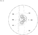
- the angle between the first frame and the second frame may be adjusted by the rotational force transmitted through a first gear, a second gear, a third gear, and a fourth gear, which constitute the first hinge.
- the angle between the first frame and the second frame may be automatically adjusted by the driving force supplied from a first motor of the first hinge.
- a metallic backplate attached to the rear surface of the flexible display may be attracted to the first hinge by the magnetic force of a magnet mounted in the first hinge.
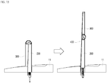
- the vehicle display device may be configured such that the protruding angle of the first frame with respect to the surface of the interior member is adjusted during a change in the screen area of the flexible display.
- the flexible display may be unfolded in response to the protruding angle of the first frame with respect to the surface of the interior member being adjusted to be equal to or greater than a preset value.
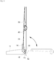
- the angle between the interior member and the first frame may be adjusted using a second hinge.
- the angle between the interior member and the first frame may be adjusted by a fifth gear, a sixth gear, and a second motor, which constitute the second hinge.
- the rotation angle of the first frame may be limited by a limiter of the second hinge.
- At least a portion of the flexible display may be wound on the first frame.
- At least a portion of the flexible display may be wound on a roller disposed at one end of the first frame.
- the portion of the first frame that is inserted into the interior member may be exposed to the outside of the interior member when the flexible display is unfolded.
- the extra portion of the flexible display that is wound on the roller may be spread corresponding to the exposure of the first frame to the outside of the interior member.
- the first frame may be moved into and out of the interior member by an ascending/descending body and a linear actuator.
- the vehicle display device has the following effects.
- the flexible display which is disposed on one surface of the first frame and one surface of the second frame, is foldable in the direction in which the one surface of the first frame and the one surface of the second frame overlap each other, it is possible to optimally change the screen area of the flexible display according to the needs of the user.
- auxiliary display is disposed on the opposite surface of the second frame, it is possible to implement a display function using the auxiliary display when the flexible display is in the folded state.
- the elastic part in response to the flexible display being unfolded, applies tension to the flexible display so as to maintain the flatness of the surface of the flexible display. Accordingly, when the screen area of the flexible display is changed, the display function of the flexible display may be consistently maintained.
- the elastic part since the elastic part applies tension to the flexible display using the elastic force generated by an elastic shaft, a moving body, a connector, and an elastic body, it is possible to more stably apply tension to the flexible display.
- the elastic part since the elastic part applies tension to the flexible display by pulling a support bar disposed at an end portion of the flexible display in the width direction of the flexible display, the tension applied to the end portion of the flexible display may be evenly dispersed in the width direction of the flexible display.
- the first frame protrudes upwards above the surface of an interior member and the second frame is disposed so as not to be parallel to the first frame, it is possible to prevent the flexible display from being excessively folded, thus minimizing damage thereto or deterioration in the function thereof.
- the angle between the first frame and the second frame is adjusted using a first hinge, it is possible for the user to appropriately adjust the angle between the first frame and the second frame according to user needs.
- the angle between the first frame and the second frame is adjusted by the rotational force transmitted through a first gear, a second gear, a third gear, and a fourth gear, which constitute the first hinge, it is possible to more smoothly and easily adjust the angle between the first frame and the second frame.
- the angle between the first frame and the second frame is automatically adjusted by the driving force supplied from a first motor of the first hinge, it is possible to more easily adjust the angle between the first frame and the second frame without the necessity of manual operation by the user.
- a metallic backplate attached to the rear surface of the flexible display is attracted to the first hinge by the magnetic force of a magnet mounted in the first hinge, it is possible to prevent the occurrence of a gap between the flexible display and the first hinge during a change in the screen area of the flexible display.
- the flexible display since the flexible display is unfolded in response to the protruding angle of the first frame with respect to the surface of the interior member being adjusted to be equal to or greater than a preset value, it is possible to prevent interference between components during the change in the screen area of the flexible display.
- the angle between the interior member and the first frame is adjusted using a second hinge, it is possible for the user to appropriately adjust the angle between the interior member and the first frame according to the needs of the user.
- the angle between the interior member and the first frame is adjusted by a fifth gear, a sixth gear, and a second motor, which constitute the second hinge, it is possible to more smoothly and easily adjust the angle between the interior member and the first frame.
- the rotation angle of the first frame is limited by a limiter of the second hinge, it is possible to prevent the first frame from being rotated in an unnecessary direction, thus preventing deterioration in the usability of the vehicle display device.
- the flexible display since at least a portion of the flexible display is wound on the first frame, it is possible to secure an extra portion of the flexible display, thereby further increasing the screen area of the flexible display.
- the portion of the first frame that is inserted into the interior member is exposed to the outside of the interior member when the flexible display is unfolded, it is possible to further increase the height that the flexible display protrudes upwards above the surface of the interior member when unfolded.
- the extra portion of the flexible display that is wound on the roller is spread corresponding to the exposure of the first frame to the outside of the interior member, it is possible to additionally increase the screen area of the flexible display when the flexible display is unfolded.
- the first frame is moved into and out of the interior member by an ascending/descending body and a linear actuator, it is possible to more smoothly and easily move the first frame.
- first, second, third, and the like may be used herein to describe various elements, components, regions, layers, and/or sections, these elements, components, regions, layers, and/or sections should not be limited by these terms. These terms are generally only used to distinguish one element from another.
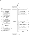
- FIG. 1 is a block diagram for explaining a vehicle display device 100 according to the present disclosure.
- the vehicle display device 100 includes a wireless transceiver 110, an input interface 120, a sensor 140, an output interface 150, an interface 160, a memory 170, a controller 180, and a power supply 190.
- a wireless transceiver 110 receives a wireless signal from a wireless transceiver 110 from a wireless transceiver 110 and a wireless signal.
- the wireless transceiver 110 may include one or more modules which enable wireless communication between the vehicle display device 100 and a wireless communication system, between the vehicle display device 100 and another vehicle display device 100, or between the vehicle display device 100 and an external server. Further, the wireless transceiver 110 may include one or more modules which connect the vehicle display device 100 to one or more networks.
- the wireless transceiver 110 may include at least one of a broadcasting receiving module 111, a mobile communication module 112, a wireless Internet module 113, a short-range communication module 114, or a position information module 115.
- the input interface 120 may include a camera 121 or an image input interface which receives input of an image signal, a microphone 122 or an audio input interface which receives input of an audio signal, and a user input interface 123 (for example, a touch key or a mechanical key) which receives information from a user. Voice data or image data collected by the input interface 120 is analyzed and processed as a control command of the user.
- the sensor 140 may include one or more sensors which sense at least one of information in the vehicle display device, surrounding environment information around the vehicle display device, or user information.
- the sensor 140 may include at least one of a proximity sensor 141, an illumination sensor 142, a touch sensor, an acceleration sensor, a magnetic sensor, a G-sensor, a gyroscope sensor, a motion sensor, an RGB sensor, an infrared (IR) sensor, a finger scan sensor, an ultrasonic sensor, an optical sensor (for example, a camera 121 or a microphone 122), a battery gauge, an environment sensor (for example, a barometer, a hygrometer, a thermometer, a radiation sensor, a thermal sensor, and a gas sensor), or a chemical sensor (for example, an electronic nose, a healthcare sensor, and a biometric sensor).
- the vehicle display device disclosed in the present specification may combine and utilize information sensed by at least two sensors from the above-mentioned sensors.
- the output interface 150 generates outputs related to visual, auditory, or tactile senses, and may include at least one of a display 151, a sound output interface 152, a haptic module 153, or an optical output interface 154.
- the display 151 may be configured as a touch screen by forming a mutual layered structure with a touch sensor or being formed integrally therewith.
- the touch screen may simultaneously serve as a user input interface 123 for providing an input interface between the vehicle display device 100 and the user and an output interface between the vehicle display device 100 and the user.
- the interface 160 serves as a passage between various types of external devices which are connected to the vehicle display device 100.
- the interface 160 may include at least one of a wired/wireless headset port, an external charger port, a wired/wireless data port, a memory card port, a port which connects a device equipped with an identification module, an audio input/output (I/O) port, a video input/output (I/O) port, or an earphone port.
- the vehicle display device 100 may perform appropriate control related to the connected external device in accordance with the connection of the external device to the I/O connector 160.
- the memory 170 may store data which supports various functions of the vehicle display device 100.
- the memory 170 may store a plurality of application programs or applications that are driven by the vehicle display device 100, data for operating the vehicle display device 100, and instructions. At least some of the application programs may be downloaded via an external server through wireless communication. Further, at least some of the application programs, related to basic functions of the vehicle display device 100 (for example, incoming and outgoing call functions, and message receiving and sending functions), may be installed in the vehicle display device 100 from the time of release.
- the application programs are stored in the memory 170, and are installed in the vehicle display device 100 and driven by the controller 180 to perform operations (or functions) of the vehicle display device.
- the controller 180 may generally control the overall operation of the vehicle display device 100.
- the controller 180 may process signals, data, or information which is inputted or outputted through the above-described components, or drive the application programs stored in the memory 170 to provide or process appropriate information or functions to the user.
- the controller 180 may control at least some of the components described with reference to FIG. 1 . Moreover, the controller 180 may combine and operate at least two of the components included in the vehicle display device 100 to drive the application program.
- the power supply 190 receives application of external power, and supplies the power to the respective components included in the vehicle display device 100 under the control of the controller 180. At least some of the above-described components may operate in cooperation with each other to implement the operation, the control, or the control method of the vehicle display device according to various embodiments, which will be described below. Further, the operation, the control, or the control method of the vehicle display device may be implemented in the vehicle display device by driving at least one application program stored in the memory 170.
- the broadcasting receiving module 111 of the wireless transceiver 110 receives a broadcasting signal and/or broadcasting-related information from an external broadcasting management server through a broadcasting channel.
- the broadcasting channel may include a satellite channel and a ground wave channel.
- Two or more broadcasting receiving modules for simultaneous broadcasting reception or broadcasting channel switching for at least two broadcasting channels may be provided in the vehicle display device 100.
- the broadcasting management server may refer to a server which generates and transmits a broadcasting signal and/or broadcasting-related information, or a server which is supplied with a previously generated broadcasting signal and/or broadcasting-related information and transmits the broadcasting signal and/or the broadcasting-related information to the vehicle display device.
- the broadcasting signal includes not only a TV broadcasting signal, a radio broadcasting signal, and a data broadcasting signal, but also a broadcasting signal obtained by combining a TV broadcasting signal or a radio broadcasting signal with a data broadcasting signal.
- the broadcasting signal may be encoded according to at least one technical standard for transmitting and receiving a digital broadcasting signal (or broadcasting schemes, for example, ISO, IEC, DVB, or ATSC), and the broadcasting receiving module 111 may receive the digital broadcasting signal using an appropriate method for the technical specification determined by the technical standard.
- a digital broadcasting signal or broadcasting schemes, for example, ISO, IEC, DVB, or ATSC
- the broadcasting receiving module 111 may receive the digital broadcasting signal using an appropriate method for the technical specification determined by the technical standard.
- the broadcasting-related information may refer to information related to a broadcasting channel, a broadcasting program, or a broadcasting service provider.
- the broadcasting-related information may also be provided through the mobile communication network. In this case, the broadcasting-related information may be received by the mobile communication module 112.
- the broadcasting-related information may exist in various types such as an electronic program guide of digital multimedia broadcasting (DMB) or an electronic service guide of a digital video broadcast-handheld (DVB-H).
- DMB digital multimedia broadcasting
- DVD-H digital video broadcast-handheld
- the broadcasting signal and/or the broadcasting-related information received by the broadcasting receiving module 111 may be stored in the memory 170.
- the modem 112 may transmit/receive a wireless signal to/from at least one among a base station, an external terminal, or a server on a mobile communication network established according to the technical standards or communication methods for mobile communication (for example, Global System for Mobile communication (GSM), Code Division Multi Access (CDMA), Code Division Multi Access 2000 (CDMA2000), Enhanced Voice-Data Optimized or Enhanced Voice-Data Only (EV-DO), Wideband CDMA (WCDMA), High Speed Downlink Packet Access (HSDPA), High Speed Uplink Packet Access (HSUPA), Long Term Evolution (LTE), and Long Term Evolution-Advanced (LTE-A)).
- GSM Global System for Mobile communication
- CDMA Code Division Multi Access
- CDMA2000 Code Division Multi Access 2000
- EV-DO Enhanced Voice-Data Optimized or Enhanced Voice-Data Only
- WCDMA Wideband CDMA
- HSDPA High Speed Downlink Packet Access
- HSUPA High Speed Uplink Packet Access
- LTE Long Term Evolution
- the wireless signal may include a voice call signal, a video call signal, or various types of data in accordance with transmission or reception of a text/multimedia message.
- the wireless Internet module 113 refers to a module for wireless Internet access and may be built in or external to the vehicle display device 100.
- the wireless Internet module 113 may be configured to transmit/receive a wireless signal in a communication network according to wireless Internet technologies.
- Wireless Internet technologies may include wireless LAN (WLAN), wireless fidelity (Wi-Fi), Wi-Fi direct, Digital Living Network Alliance (DLNA), wireless broadband (WiBro), Worldwide Interoperability for Microwave Access (WiMAX), High Speed Downlink Packet Access (HSDPA), High Speed Uplink Packet Access (HSUPA), Long Term Evolution (LTE), and Long Term Evolution-Advanced (LTE-A).
- the wireless Internet module 113 may transmit or receive data in accordance with at least one wireless Internet technology, including Internet technologies which have not been described above.
- the wireless Internet module 113 which performs the wireless Internet connection through the mobile communication network may be understood as a type of the mobile communication module 112.
- the short-range communication module 114 may support short-range communication using at least one of BluetoothTM, radio frequency identification (RFID), infrared data association (IrDA), ultra wideband (UWB), ZigBee, Short-range Communication (NFC), wireless fidelity (Wi-Fi), Wi-Fi Direct, or Wireless Universal Serial Bus (Wireless USB).
- RFID radio frequency identification
- IrDA infrared data association
- UWB ultra wideband
- ZigBee ZigBee
- NFC wireless fidelity
- Wi-Fi Wi-Fi Direct
- Wireless Universal Serial Bus Wireless Universal Serial Bus
- the short-range communication module 114 may support wireless communication between the vehicle display device 100 and the wireless communication system, between the vehicle display device 100 and another vehicle display device 100, or between the vehicle display device 100 and a network in which the other vehicle display device 100 (or external server) is located, through a short-range wireless communication network.
- the short-range wireless communication network may be a short-range wireless personal communication network.
- the GNSS sensor 115 is a module for obtaining the location (or the current location) of a vehicle display device, and its representative examples include a global positioning system (GPS) module or a Wi-Fi module.
- GPS global positioning system
- the vehicle display device may obtain the position of the vehicle display device using a signal transmitted from a GPS satellite.
- a Wi-Fi module the vehicle display device may obtain the position of the vehicle display device based on information of a wireless access point (AP) which transmits and receives wireless signals with the Wi-Fi module.
- AP wireless access point
- the position information module 115 may perform a function of another module of the wireless transceiver 110 to substitutably or additionally obtain data on the position of the vehicle display device.
- the position information module 115 is not limited to a module which directly calculates or obtains the position of the vehicle display device.
- the input interface 120 is provided to input video information (or signals), audio information (or signals), data, or information inputted from the user.
- the vehicle display device 100 may include one or more cameras 121.
- the camera 121 processes an image frame such as a still image or a moving image obtained by an image sensor in a video call mode or a photographing mode.
- the processed image frames may be displayed on the display 151 or stored in the memory 170.
- the plurality of cameras 121 equipped in the vehicle display device 100 may be disposed to form a matrix structure, and a plurality of pieces of image information having various angles or focal points may be inputted to the vehicle display device 100 through the cameras 121 that form the matrix structure.
- the cameras 121 may be disposed to have a stereo structure to obtain a left image and a right image to implement a stereoscopic image.
- the microphone 122 processes an external sound signal as electronic voice data.
- the processed voice data may be utilized in various forms in accordance with a function being performed by the vehicle display device 100 (or an application program which is being executed).
- various noise removal algorithms which remove noise generated during the process of receiving the external sound signal may be implemented.
- the user input interface 123 receives information from the user, and when the information is inputted through the user input interface 123, the controller 180 may control the operation of the vehicle display device 100 so as to correspond to the inputted information.
- the user input interface 123 may include a mechanical input interface (or a mechanical key, for example, a button located on a front, rear, or side surface of the vehicle display device 100, a dome switch, a jog wheel, a jog switch, or the like) and a touch type input interface.
- the touch type input interface may include a virtual key, a soft key, or a visual key displayed on the touch screen via a software process, or may include a touch key disposed on a portion other than the touch screen.
- the virtual key or the visual key may be displayed on the touch screen in various shapes, and for example, may be formed by graphics, text, icons, video, or a combination thereof.
- the sensor 140 senses at least one of information in the vehicle display device, surrounding environment information around the vehicle display device, or user information, and generates a sensing signal corresponding to the information.
- the controller 180 may control the driving or the operation of the vehicle display device 100 or perform data processing, functions, or operations related to the application programs installed in the vehicle display device 100, based on the sensing signal. Representative sensors among the various sensors which may be included in the sensor 140 will be described in more detail below.
- the proximity sensor 141 is a sensor which senses the presence of an object approaching a predetermined sensing surface or nearby objects, using an electromagnetic field force or infrared ray without any mechanical contact.
- the proximity sensor 141 may be disposed in an internal area of the vehicle display device, which is enclosed by the above-described touch screen, or in the vicinity of the touch screen.
- Examples of the proximity sensor 141 may include a transmission type photoelectric sensor, a direct reflection type photoelectric sensor, a mirror reflection type photoelectric sensor, a high frequency oscillation type proximity sensor, a capacitive proximity sensor, a magnetic proximity sensor, and an infrared proximity sensor.
- the proximity sensor 141 may be configured to detect the proximity of the object with a change in the electric field in accordance with the proximity of the object having conductivity. In this case, the touch screen (or the touch sensor) itself may be classified as a proximity sensor.
- proximity touch when an object approaches the touch screen without contacting the touch screen, and it is recognized that the object is located above the touch screen, it is referred to as a "proximity touch.”
- contact touch When the object actually touches the touch screen, it is referred to as a “contact touch”.
- a position at which the object proximately touches the touch screen refers to a position at which the object vertically corresponds to the touch screen when the object proximately touches the touch screen.
- the proximity sensor 141 may sense a proximate touch and a proximate touch pattern (for example, a proximate touch distance, a proximate touch direction, a proximate touch speed, a proximate touch time, a proximate touch position, a proximate touch movement state, etc.).
- the controller 180 may process data (or information) corresponding to the proximate touch operation and the proximate touch pattern sensed by the proximity sensor 141, and may further output visual information corresponding to the processed data on the touch screen.
- the controller 180 may control the vehicle display device 100 to process different operations or data (or information) depending on whether the touch on the same point on the touch screen is a proximity touch or a contact touch.
- the touch sensor senses a touch (or a touch input) applied to the touch screen (or the display 151) using at least one of various touch types such as a resistive film type, a capacitive type, an infrared type, an ultrasonic type, and a magnetic field type.
- various touch types such as a resistive film type, a capacitive type, an infrared type, an ultrasonic type, and a magnetic field type.
- the touch sensor may be configured to convert a change of a pressure which is applied to a specific portion of the touch screen, or a capacitance which is generated in a specific portion, into an electrical input signal.
- the touch sensor may be configured to detect a position and an area where a touch subject which applies a touch onto the touch screen is touched on the touch sensor, and a capacitance at the time of the touch.
- the touch subject is an object which applies a touch to the touch sensor, and may include, for example, a finger, a touch pen, a stylus pen, and a pointer.
- the touch controller processes the signal(s) and then transmits corresponding data to the controller 180.
- the controller 180 may confirm which area of the display 151 is touched.
- the touch controller may be a separate component from the controller 180, or may be the controller 180 itself.
- the controller 180 may perform different control or the same control depending on a type of a touch subject which touches the touch screen (or a touch key equipped other than the touch screen). Whether to perform the different control or the same control depending on the type of touch subject may be determined in accordance with an operating state of the current vehicle display device 100 or an application program which is being executed.
- the touch sensor and proximity sensor described above may, independently or in combination, sense various types of touches on the touch screen, such as a short (or tap) touch, a long touch, a multi touch, a drag touch, a flick touch, a pinch-in touch, a pinch-out touch, a swipe touch, or a hovering touch.
- the ultrasonic sensor may recognize position information of a sensing object using an ultrasonic wave.
- the controller 180 may calculate a position of a wave generating source by information sensed by the optical sensor and the plurality of ultrasonic sensors.
- a position of the wave generating source may be calculated using the property that light is much faster than an ultrasonic wave, that is, the time in which light reaches the optical sensor is much faster than the time in which the ultrasonic wave reaches the ultrasonic sensor. More specifically, the position of the wave generating source may be calculated using a time difference of the time of arrival of the ultrasonic wave with respect to light which serves as a reference signal.
- the camera 121 includes at least one of a camera sensor (for example, a CCD or a CMOS), a photo sensor (or an image sensor), or a laser sensor.
- a camera sensor for example, a CCD or a CMOS
- a photo sensor or an image sensor
- a laser sensor for example, a laser sensor
- the camera 121 and the laser sensor may be combined to sense a touch of a sensing object for a three-dimensional stereoscopic image.
- the photo sensor which is laminated on a display element, is configured to scan a motion of a sensing object proximate to the touch screen. More specifically, the photo sensor is formed by mounting photo diodes and transistors (TR) in rows/columns to scan contents which are disposed on the photo sensor using an electrical signal that changes in accordance with an amount of light applied to the photo diode. That is, the photo sensor calculates coordinates of a sensing object in accordance with a changed amount of light, and position information of the sensing object may be obtained through the coordinates.
- TR photo diodes and transistors
- the display 151 displays (outputs) information processed in the vehicle display device 100.
- the display 151 may display execution screen information of an application program driven in the vehicle display device 100 and user interface (UI) and graphic user interface (GUI) information in accordance with the execution screen information.
- UI user interface
- GUI graphic user interface
- the display 151 may be configured as a stereoscopic display which displays a stereoscopic image.
- a three-dimensional display type such as a stereoscopic type (a glass type), an autostereoscopic type (a glass-free type), a projection type (a holographic type) may be applied to the stereoscopic display.
- the speaker 152 may output audio data received from the wireless transceiver 110 or stored in the memory 170 in a call signal reception mode, a phone-call mode, a recording mode, a speech recognition mode, or a broadcasting reception mode.
- the sound output interface 152 may also output a sound signal related to a function (for example, a call signal reception sound or a message reception sound) performed in the vehicle display device 100.
- a sound output interface 152 may include, for example, a receiver, a speaker, and a buzzer.
- the haptic module 153 may generate various tactile effects that can be felt by the user.
- a representative example of the tactile effect generated by the haptic actuator 153 may be vibration.
- An intensity and a pattern of the vibration generated in the haptic module 153 may be controlled by the selection of the user or a setting of the controller 180.
- the haptic module 153 may compose different vibrations to output the composed vibrations, or sequentially output the different vibrations.
- the haptic module 153 In addition to vibration, the haptic module 153 generates various tactile effects such as effects by a pin arrangement which vertically moves to a contact skin surface, an injection force or a suction force of air through an injection port or a suction port, grazing on a skin surface, electrode contact, or stimulation of an electrostatic force or effects of reproducing a cold or hot sensation using a heat absorbing or heat emitting element.
- the haptic module 153 may not only transmit a tactile effect by means of direct contact, but may also be implemented to allow the user to feel a tactile effect by muscular sensation of a finger or an arm. Two or more haptic modules 153 may be provided in accordance with a configuration aspect of the vehicle display device 100.
- the optical output interface 154 outputs a signal for notifying occurrence of an event using light of a light source of the vehicle display device 100.
- Examples of events generated in the vehicle display device 100 may be message reception, call signal reception, missed call, alarm, schedule notification, email reception, and information reception through an application.
- the signal outputted from the optical output interface 154 is implemented as the vehicle display device emits single color or a plurality of color light to a front surface or a rear surface.
- the signal output may be completed.
- the interface 160 serves as a passage with all external devices which are connected to the vehicle display device 100.
- the interface 160 receives data from the external device or is supplied with the power source to transmit the power source to each component in the vehicle display device 100, or transmits data in the vehicle display device 100 to the external device.
- the interface 160 may include a wired/wireless headset port, an external charger port, a wired/wireless data port, a memory card port, a port which connects a device equipped with an identification module, an audio input/output (I/O) port, a video input/output (I/O) port, an earphone port, etc.
- the identification module is a chip in which various information for authenticating a usage right of the vehicle display device 100 is stored and includes a user identification module (UIM), a subscriber identification module (SIM), and a universal subscriber identity module (USIM).
- a device with an identification module (hereinafter, “identification device") may be manufactured as a smart card. Therefore, the identification device may be connected to the terminal 100 through the I/O connector 160.
- the memory 170 may store a program for an operation of the controller 180, or temporarily store input/output data (for example, a phone book, a message, a still image, a moving image, etc.).
- the memory 170 may store data on a vibration or a sound of various patterns output when the touch is inputted onto the touch screen.
- the memory 170 may include at least one type of storage medium of a flash memory type, a hard disk type, a solid state disk (SSD) type, a silicon disk drive (SDD) type, a multimedia card micro type, and card type memories (for example, SD or XD memory and the like), a random access memory (RAM), a static random access memory (SRAM), a read only memory (ROM), an electrically erasable programmable read only memory (EEPROM), a programmable read only memory (PROM), a magnetic memory, a magnetic disk, and an optical disk.
- the vehicle display device 100 may operate in association with a web storage which performs a storage function of the memory 170 on the Internet.
- the controller 180 may control an operation related to the application program and an overall operation of the vehicle display device 100. For example, when the state of the vehicle display device satisfies a predetermined condition, the controller 180 may execute or release a locking state which restricts an input of a control command of a user for the applications.
- controller 180 may perform control and processing related to voice call, data communication, and video call, or perform a pattern recognition process which recognizes a handwriting input or a picture drawing input performed on the touch screen as a text or an image, respectively. Moreover, the controller 180 may control any one or a combination of a plurality of components described above to implement various embodiments which will be described below on the vehicle display device 100 according to the present disclosure.
- the display 151 displays (outputs) information processed in the vehicle display device 100.
- the display 151 may display execution screen information of an application program driven in the vehicle display device 100 and user interface (UI) and graphic user interface (GUI) information in accordance with the execution screen information.
- UI user interface
- GUI graphic user interface
- the display 151 may include at least one of a liquid crystal display (LCD), a thin film transistor liquid crystal display (TFT LCD), an organic light emitting diode (OLED), a flexible display, a three-dimensional display (3D display), or an electronic ink display (e-ink display).
- LCD liquid crystal display
- TFT LCD thin film transistor liquid crystal display
- OLED organic light emitting diode
- flexible display a three-dimensional display
- 3D display three-dimensional display
- e-ink display electronic ink display
- two or more displays 151 may be provided in accordance with an implementation type of the vehicle display device 100.
- a plurality of displays may be disposed to be spaced apart from each other or integrally disposed on one surface of the vehicle display device 100 or may be disposed on different surfaces.
- the display 151 may include a touch sensor which senses a touch on the display 151 so as to receive the control command by the touch method. Therefore, when the touch is made on the display 151, the touch sensor senses the touch, and based on the touch the controller 180 generates a control command corresponding to the touch.
- Contents inputted by the touch method may be letters or numbers, instructions in various modes, menu items which may be designated, or the like.
- the microphone 122 is configured to receive a voice of the user, or other sounds.
- the microphone 122 is equipped in a plurality of locations to receive stereo sounds.
- the interface 160 serves as a passage through which the vehicle display device 100 is connected to the external device.
- the interface 160 may be at least one of a connection terminal for connection with other devices (for example, an earphone or an external speaker), a port for short-range communication (for example, an infrared port (IrDA port), a Bluetooth port, a wireless LAN port, etc.), or a power supply terminal for supplying a power to the vehicle display device 100.
- the interface 160 may be implemented as a socket type which accommodates an external card such as a subscriber identification module (SIM), a user identity module (UIM), and a memory card for information storage.
- SIM subscriber identification module
- UIM user identity module
- memory card for information storage.
- At least one antenna for wireless communication may be provided in a terminal body.
- the antenna may be embedded in the terminal body or formed in a case.
- the antenna which forms a part of the broadcasting receiving module 111 may be configured to be drawn from the terminal body.
- the antenna may be formed as a film type to be attached onto an inner surface of a housing, or a case including a conductive material may serve as an antenna.
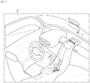
- FIG. 2 is a view exemplarily showing the state in which a vehicle display device according to an embodiment of the present disclosure is mounted in a vehicle.
- FIG. 3 is a view showing the state in which a vehicle display device according to an embodiment of the present disclosure is folded.
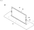
- FIG. 4 is a view showing the state in which a vehicle display device according to an embodiment of the present disclosure is unfolded.
- the vehicle display device 100 is mounted in the indoor space of a vehicle 10, and is configured such that the area of a display changes.
- the vehicle display device 100 according to an embodiment of the present disclosure includes a first frame 200, a second frame 300, and a flexible display 400.
- the first frame 200 is coupled at one end thereof to an interior member 11 of the vehicle 10, and supports a portion (a first area 401) of the flexible display 400.
- the second frame 300 is coupled at one end thereof to the opposite end of the first frame 200 so as to be rotatable about the one end thereof with respect to the first frame 200, and supports the remaining portion (a second area 402) of the flexible display 400.
- the first frame 200 and the second frame 300 rotate relative to each other at a preset angle in the state of being connected to each other.
- the flexible display 400 may be folded or unfolded.
- the flexible display 400 is disposed on one surface of the first frame 200 and one surface of the second frame 300, and is configured to be foldable in the direction in which the one surface of the first frame 200 and the one surface of the second frame 300 overlap each other.
- the flexible display 400 is disposed on the one surface of the first frame 200 and the one surface of the second frame 300 in the unfolded state.
- the screen area of the flexible display 400 is relatively large, a user may recognize information outputted through the relatively wide integrated screen of the flexible display 400.
- the flexible display 400 may be folded in the direction in which the one surface of the first frame 200 and the one surface of the second frame 300 overlap each other. In this case, the flexible display 400 is not exposed to the outside, thus being prevented from being damaged or broken. Further, the space occupied by the flexible display 400 in the interior of the vehicle 10 may be reduced.
- a user may desire to obtain various pieces of information through a relatively large screen.
- the user may first unfold the flexible display 400, and may then perform manipulation such that information such as driving information of the vehicle 10, surrounding environment information, and information on the content that the user is viewing or listening to, are displayed on the flexible display 400.
- the user when not using the vehicle display device 100, the user may desire to protect the flexible display 400, which is relatively weak, by avoiding exposure thereof to the outside.
- the vehicle display device 100 which is mounted in the vehicle 10, may be used in a hot environment in summer or in a cold environment in winter. Thus, it may be preferable to minimize exposure of the flexible display 400 when not in use.
- the controller 180 may perform control such that the flexible display 400 is automatically folded to be protected.
- information may be outputted through the first area 401 and the second area 402 of the flexible display 400 in a whole-screen mode or in a divided-screen mode.
- the display function may be optimally implemented so as to be suitable for any of various situations.
- the flexible display 400 which is disposed on one surface of the first frame 200 and one surface of the second frame 300, is foldable in the direction in which the one surface of the first frame 200 and the one surface of the second frame 300 overlap each other.
- vehicle display device 100 is illustrated in FIG. 2 as being mounted to the dashboard of the vehicle 10 so as to protrude upwards above the dashboard, the present disclosure is not limited thereto.
- the vehicle display device 100 may be mounted in any of various configurations in the interior of the vehicle 10. In one example, the vehicle display device 100 may be mounted on the ceiling of the vehicle 10 so as to protrude downwards.
- the first frame 200, the second frame 300, and the flexible display 400 may be disposed in a housing, which corresponds to a case or a cover forming the external appearance of the vehicle display device 100.
- various electronic components may be disposed in the housing.
- a bezel structure may be formed along the edge of the flexible display 400.
- the bezel structure may be formed so as to be separated into pieces at the portion thereof corresponding to the connection part between the first frame 200 and the second frame 300, thereby preventing interference with the first frame 200 and the second frame 300 during folding and unfolding of the flexible display 400.
- the vehicle display device 100 may further include an auxiliary display 800, which is disposed on the opposite surface of the second frame 300.
- the auxiliary display 800 is configured to perform a display function separately from the flexible display 400.
- the auxiliary display 800 is disposed so as to output information at all times in a direction opposite the direction in which the flexible display 400 outputs information, even when the flexible display 400 is folded and unfolded.
- the user may confirm information outputted through the auxiliary display 800.
- the user may desire that only essential information, such as information pertaining to driving of the vehicle 10, is displayed on the auxiliary display 800 in the state in which the screen area of the flexible display 400 is minimized.
- information pertaining to driving of the vehicle 10 is displayed on the auxiliary display 800 in the state in which the screen area of the flexible display 400 is minimized.
- the user may perform manipulation such that the flexible display 400 is folded and only essential information is displayed on the minimized screen through the auxiliary display 800.
- the vehicle display device 100 may be controlled such that only very simple information, such as the phone number of the user, is displayed on the auxiliary display 800 so as to be shown to a person present outside the vehicle 10.
- auxiliary display 800 is disposed on the opposite surface of the second frame 300, it is possible to implement a display function using the auxiliary display 800 when the flexible display 400 is in the folded state.
- FIGS. 5 and 6 are cross-sectional views showing a vehicle display device according to an embodiment of the present disclosure.
- the vehicle display device 100 may further include an elastic part 500, which applies tension to the flexible display 400 in a direction oriented toward the inside of the interior member 11 when the flexible display 400 is unfolded.
- the length of the flexible display 400 which is disposed on one surface of the first frame 200 and one surface of the second frame 300, may not be exactly identical to the sum of the length of the first frame 200 and the length of the second frame 300.
- the length of the flexible display 400 in the folded state may correspond to the sum of the length of the first frame 200 and the length of the second frame 300
- the length of the flexible display 400 in the unfolded state may not be identical to the sum of the length of the first frame 200 and the length of the second frame 300.
- the flexible display 400 may not be securely supported by the first frame 200 and the second frame 300 in the unfolded state, and a portion thereof may be wrinkled or crooked.
- the display function of the vehicle display device 100 may not be smoothly implemented.
- an image outputted through the flexible display 400 may be distorted.
- the elastic part 500 in response to the flexible display 400 being unfolded, applies tension to the flexible display 400 so as to maintain the flatness of the surface of the flexible display 400.
- the display function of the flexible display 400 may be consistently maintained.
- the elastic part 500 may include an elastic shaft 510, a moving body 520, a connector 530, and an elastic body 540.
- the elastic shaft 510 is a part that protrudes from one end of the first frame 200 and is mounted in the interior member 11.
- the elastic shaft 510 may guide the direction in which tension is applied to the flexible display 400.
- the moving body 520 is configured to apply tension to the flexible display 400 while moving in the longitudinal direction of the elastic shaft 510.
- tension may be applied to the flexible display 400 in a direction parallel to the longitudinal direction of the elastic shaft 510.
- the moving body 520 is a part that is coupled to the elastic shaft 510 so as to be movable in the longitudinal direction of the elastic shaft 510. Movement of the moving body 520 in directions other than the longitudinal direction of the elastic shaft 510 may be restrained, and thus the direction in which tension is applied to the flexible display 400 may be set as described above.
- the connector 530 is a part that connects the flexible display 400 and the moving body 520 to each other. In response to the moving body 520 moving as described above, tension may be transmitted to the flexible display 400 connected to the moving body 520 via the connector 530.
- the elastic body 540 is a part that is interposed between the moving body 520 and one end of the first frame 200 so as to apply elastic force to the moving body 520 with respect to the one end of the first frame 200. That is, the elastic body 540 may bias the moving body 520 away from the one end of the first frame 200 using the elastic force thereof. As such the moving body 520 may be moved.
- the moving body 520 may be moved in the longitudinal direction of the elastic shaft 510 by the elastic force of the elastic body 540, and the connector 530 connected to the moving body 520 may pull the flexible display 400. In this manner, tension may be applied to the flexible display 400.
- the elastic part 500 may apply tension to the flexible display 400 using the elastic force generated by the elastic shaft 510, the moving body 520, the connector 530, and the elastic body 540. As a result, it is possible to more stably apply tension to the flexible display 400.
- a support bar 550 may be disposed at an end portion of the flexible display 400 in the width direction of the flexible display 400.
- the connector 530 may be coupled at one end thereof to the support bar 550, and may be coupled at the opposite end thereof to the moving body 520.
- the connector 530 pulls the flexible display 400 as described above, if tension is applied only to a specific portion of the flexible display 400, the flexible display 400 may be deformed or skewed by eccentric force.
- the support bar 550 which is formed in a tubular or rod configuration, may be coupled to the end portion of the flexible display 400 in the width direction of the flexible display 400, and the connector 530 may pull the support bar 550. As such, it is possible to prevent application of eccentric force to a specific portion of the flexible display 400.
- the elastic part 500 applies tension to the flexible display 400 by pulling the support bar 550 disposed at the end portion of the flexible display 400 in the width direction of the flexible display 400.
- the tension applied to the end portion of the flexible display 400 may be evenly dispersed in the width direction of the flexible display 400.
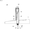
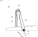
- FIG. 7 is a view exemplarily showing the arrangement of the first frame and the second frame in a vehicle display device according to an embodiment of the present disclosure.
- the first frame 200 may protrude upwards above the surface of the interior member 11, and the second frame 300 may be disposed so as not to be parallel to the first frame 200.
- the flexible display 400 may be folded up to an angle at which the one surface of the first frame 200 and the one surface of the second frame 300 do not contact each other. Accordingly, the angle formed between the first frame 200 and the second frame 300 may vary within a range greater than 0° and equal to or less than 180°.
- the curvature with which the boundary area between the first area 401 and the second area 402 of the flexible display 400 is folded relatively decreases, and the amount of stress concentrated on the folded portion of the flexible display 400 may thus be reduced.
- the flexible display 400 is less likely to be damaged or deformed.
- the above-described functions of displaying information to the inside and the outside of the vehicle 10 and protecting the flexible display 400 may still be smoothly implemented.
- the vehicle display device 100 is configured such that the first frame 200 protrudes upwards above the surface of the interior member 11 and such that the second frame 300 is disposed so as not to be parallel to the first frame 200, thereby preventing the flexible display 400 from being excessively folded, and consequently minimizing damage thereto or deterioration in the function thereof.
- the vehicle display device 100 may further include a first hinge 600, which is interposed between the first frame 200 and the second frame 300 so as to connect the second frame 300 to the first frame 200.
- the first hinge 600 serves to adjust a coupling angle between the second frame 300 and the first frame 200.
- first frame 200 and the second frame 300 are connected to each other via the first hinge 600.
- the coupling angle between the first frame 200 and the second frame 300 may be adjusted through the rotation of the first hinge 600 relative to the first frame 200 and the rotation of the second frame 300 relative to the first hinge 600.
- the rotational degree of freedom of each component may increase above that when the first frame 200 and the second frame 300 are directly connected to each other.
- the angle between the first frame 200 and the second frame 300 is adjusted using the first hinge 600. As a result, it is possible for the user to appropriately adjust the angle between the first frame 200 and the second frame 300 according to the user needs.
- FIGS. 8 and 9 are views showing the first hinge of a vehicle display device according to an embodiment of the present disclosure in more detail.
- the first hinge 600 may include a first gear 610, a second gear 620, a third gear 630, and a fourth gear 640.
- the first gear 610 may be mounted to the opposite end of the first frame 200 such that the rotation angle thereof is restricted by the first frame 200.
- the arrangement angle of the first frame 200 may be changed according to the rotation of the first gear 610.
- the second gear 620 may be mounted to the one end of the second frame 300 such that the rotation angle thereof is restricted by the second frame 300.
- the arrangement angle of the second frame 300 may be changed according to the rotation of the second gear 620.
- the third gear 630 may be threadedly engaged with the first gear 610 so as to be rotatable with respect to the first gear 610.
- the first gear 610 may be rotated in conjunction with the rotation of the third gear 630.
- the fourth gear 640 may be threadedly engaged both with the second gear 620 and with the third gear 630 so as to transmit rotational force between the second gear 620 and the third gear 630.
- the second gear 620 and the third gear 630 may be rotated in conjunction with the rotation of the fourth gear 640.
- the second frame 300 In response to external force being applied to the second frame 300, the second frame 300 is moved such that the arrangement angle of the second frame 300 with respect to the first frame 200 increases, and the flexible display 400 is thus unfolded. As such, the second gear 620 mounted to the second frame 300 is rotated in the counterclockwise direction.
- the fourth gear 640 In response to the second gear 620 being rotated, the fourth gear 640, threadedly engaged with the second gear 620, is rotated in the clockwise direction.
- the third gear 630 threadedly engaged with the fourth gear 640, is rotated in the counterclockwise direction according to the rotation of the fourth gear 640.
- rotational force in the clockwise direction is applied to the first gear 610, which is threadedly engaged with the third gear 630.
- the rotation of the first frame 200 may be restrained by the interior member 11. Therefore, although rotational force is applied to the first gear 610, the rotation of the first frame 200 is restrained, and thus the rotational force applied to the first gear 610 may reversely accelerate the counterclockwise rotation of the third gear 630.
- the clockwise rotation of the fourth gear 640 and the counterclockwise rotation of the second gear 620 may be sequentially accelerated.
- the unfolding operation of the second frame 300 may be further accelerated, and the second frame 300 may be changed to the state shown in FIG. 9 .
- the angle between the first frame 200 and the second frame 300 is adjusted by the rotational force transmitted through the first gear 610, the second gear 620, the third gear 630, and the fourth gear 640, which constitute the first hinge 600.
- the angle between the first frame 200 and the second frame 300 may be adjusted more smoothly and easily.
- the first hinge 600 may further include a first motor 650, which is coupled to the fourth gear 640 in order to provide driving force to the fourth gear 640 to rotate the same.
- the first gear 610, the second gear 620, and the third gear 630 may be respectively rotated as described above, and the folded state and the unfolded state of the flexible display 400 may be automatically adjusted.
- the controller based on the operation of the first motor 650 being controlled in stages by the controller, it is also possible to adjust, in stages, the degree to which the flexible display 400 is folded or unfolded.
- the angle between the first frame 200 and the second frame 300 is automatically adjusted by the driving force supplied from the first motor 650 of the first hinge 600. As a result, it is possible to more easily adjust the angle between the first frame 200 and the second frame 300 without the necessity of manual operation by the user.
- FIG. 10 is a view showing a backplate and a magnet of a vehicle display device according to an embodiment of the present disclosure.
- the vehicle display device 100 may further include a backplate 410 and a magnet 660.
- the backplate 410 is a metallic part that is attached to the rear surface of the flexible display 400 and is disposed on one surface of the first frame 200 and one surface of the second frame 300.
- the backplate 410 may support a specific portion of the rear surface of the flexible display 400 in a flat surface state.
- the backplate 410 may also be formed of a flexible material that is bendable so that the flexible display 400 is smoothly folded and unfolded.
- the magnet 660 is mounted in the first hinge 600 in order to enable close contact between the backplate 410 and the first hinge 600 using the magnetic force thereof.
- the magnet 660 may prevent the occurrence of a gap between the backplate 410 and the first hinge 600 during a change in the shape of the flexible display 400.
- wrinkles or irregularities may occur in a portion of the flexible display 400 in the unfolded state, which may cause a gap to form between the first hinge 600 and the portion of the flexible display 400 that cannot be fixedly attached to the first hinge 600 to change the curvature thereof.
- the magnet 660 is mounted in the first hinge 600, and the metallic backplate 410 is attached to the rear surface of the flexible display 400, thereby minimizing the occurrence of a gap between the flexible display 400 and the first hinge 600 using the magnetic force of the magnet 660.
- the magnetic force of the magnet 660 is effective in attracting the backplate 410, but does not obstruct the sliding movement of the backplate 410 in the longitudinal direction of the flexible display 400, so that the flexible display 400 is smoothly folded and unfolded.
- the metallic backplate 410 attached to the rear surface of the flexible display 400 is attracted to the first hinge 600 by the magnetic force of the magnet 660, it is possible to prevent the occurrence of a gap between the flexible display 400 and the first hinge 600 during the change in the screen area of the flexible display 400.
- FIG. 11 is a view exemplarily showing the operation of changing an angle at which the first frame protrudes upwards with respect to the surface of the interior member in a vehicle display device according to an embodiment of the present disclosure.
- the first frame 200 is mounted such that the angle at which the first frame 200 protrudes upwards with respect to the surface of the interior member 11 (hereinafter, referred to as a "protruding angle") is changeable.
- the flexible display 400 may be unfolded in response to the protruding angle of the first frame 200 being equal to or greater than a preset value.
- the preset value may be an arbitrary angular value that is separately set by the user or preset in the process of manufacturing the vehicle display device 100.
- the preset value may be a value that is set to allow the unfolding operation of the flexible display 400 only when the vehicle display device 100 is being used.
- the user may desire to minimize the amount of the flexible display 400 that protrudes above the surface of the interior member 11 in order to prevent the field of vision of the user from being blocked or to prevent interference with other components.
- the user may lay the vehicle display device 100 down by reducing the protruding angle of the first frame 200. Further, in this case, the flexible display 400 may not need to be unfolded.
- the user may cause the vehicle display device 100 to protrude upwards by increasing the protruding angle of the first frame 200.
- the flexible display 400 may be naturally unfolded so as to increase user convenience.
- the flexible display 400 is unfolded in response to the protruding angle of the first frame 200 with respect to the surface of the interior member 11 being adjusted to be equal to or greater than a preset value, it is possible to prevent interference between components during the change in the screen area of the flexible display 400.
- the vehicle display device 100 may further include a second hinge 700, which is interposed between the first frame 200 and the interior member 11 so as to connect the first frame 200 to the interior member 11.
- the second hinge 700 serves to adjust the coupling angle between the first frame 200 and the interior member 11.
- first frame 200 and the interior member 11 are connected to each other via the second hinge 700.
- the coupling angle between the first frame 200 and the interior member 11 may be adjusted through the rotation of the second hinge 700 relative to the interior member 11 and the rotation of the first frame 200 relative to the second hinge 700.
- the rotational degree of freedom of each component may increase above that when the first frame 200 and the interior member 11 are directly connected to each other.
- the angle between the interior member 11 and the first frame 200 is adjusted using the second hinge 700. As a result, it is possible for the user to appropriately adjust the angle between the interior member 11 and the first frame 200 according to user needs.
- the second hinge 700 may include a fifth gear 710, a sixth gear 720, and a second motor 730.
- the fifth gear 710 may be mounted in the interior member 11.
- the fifth gear 710 may be mounted such that the movement thereof in all directions is restrained, but the rotation thereof is not restrained by the interior member 11.
- the sixth gear 720 may be mounted to the one end of the first frame 200 such that the rotation angle thereof is restricted by the first frame 200.
- the sixth gear 720 may be threadedly engaged with the fifth gear 710.
- the arrangement angle of the first frame 200 may be changed according to the rotation of the sixth gear 720. Further, the sixth gear 720 may be rotated in conjunction with the rotation of the fifth gear 710.
- the second motor 730 may be coupled to the fifth gear 710 in order to provide driving force to the fifth gear 710 to rotate the same.
- the sixth gear 720 may be rotated, and the rotation angle of the first frame 200 may be automatically adjusted.
- the angle between the interior member 11 and the first frame 200 is adjusted by the fifth gear 710, the sixth gear 720, and the second motor 730, which constitute the second hinge 700. As a result, it is possible to more smoothly and easily adjust the angle between the interior member 11 and the first frame 200.
- the second hinge 700 may further include a limiter 740 for limiting the rotation angle of the first frame 200.
- the vehicle display device 100 when the vehicle display device 100 is made to protrude upwards so as to be used, it is not preferable for the first frame 200 to be rotated far enough that the vehicle display device 100 is laid down in the opposite direction.
- the screen area of the flexible display 400 In response to the amount of the vehicle display device 100 that protrudes upwards above the interior member 11 increasing, the screen area of the flexible display 400, through which the user is capable of visually recognizing information, increases. Therefore, it is necessary to limit the rotation angle of the first frame 200 to within a predetermined range.
- the limiter 740 is mounted in order to prevent the first frame 200 from being laid down in the opposite direction, thereby optimizing the use state of the vehicle display device 100.
- the rotation angle of the first frame 200 is limited by the limiter 740 of the second hinge 700, it is possible to prevent the first frame 200 from being rotated in an unnecessary direction, thus preventing deterioration in the usability of the vehicle display device 100.
- FIG. 12 is a view exemplarily showing the configuration in which a portion of the flexible display 400 is wound on the first frame in a vehicle display device according to an embodiment of the present disclosure.
- the flexible display 400 may be disposed such that at least a portion thereof is wound on the first frame 200.
- the length of the flexible display 400 may not be exactly identical to the sum of the length of the first frame 200 and the length of the second frame 300. Therefore, the length of the flexible display 400 needs to be adjusted to some extent during the folding and unfolding operation.
- the flexible display 400 may be desirable for the flexible display 400 to have an extra portion having a predetermined length. Accordingly, the extra portion of the flexible display 400 needs to be disposed so as to avoid exposure to the outside when not in use.
- the vehicle display device 100 since at least a portion of the flexible display 400 is wound on the first frame 200, it is possible to secure an extra portion of the flexible display 400, thereby further increasing the screen area of the flexible display 400.
- the first frame 200 may include a roller 210, which is disposed at the one end of the first frame 200 and is configured such that at least a portion of the flexible display 400 is wound thereon. That is, as shown in FIG. 12 , the extra portion of the flexible display 400 may be stored in the state of being wound on the roller 210 disposed at the one end of the first frame 200.
- the extra portion of the flexible display 400 needs to be disposed so as to avoid exposure to the outside when not in use.
- it may not only require a relatively large storage space, but may also cause interference with other components of the vehicle 10.
- the extra portion of the flexible display 400 is wound on the roller 210 in order to solve the problems associated with storage space and interference between components.
- the vehicle display device 100 since at least a portion of the flexible display 400 is wound on the roller 210 disposed at the one end of the first frame 200, it is possible to easily store the extra portion of the flexible display 400.
- FIG. 13 is a view exemplarily showing the movement of the first frame of a vehicle display device according to an embodiment of the present disclosure.
- FIG. 14 is a view showing the first frame of a vehicle display device according to an embodiment of the present disclosure in more detail.
- a portion of the first frame 200 may be inserted into the interior member 11, and the portion of the first frame 200 may be moved so as to be exposed to the outside of the interior member 11 when the flexible display 400 is unfolded.
- the one end of the first frame 200 may be mounted so as to be inserted into the interior member 11.
- the insertion depth of the one end of the first frame 200 may be maximized in order to minimize the protruding height of the flexible display 400 when not in use.
- the portion of the first frame 200 that is inserted into the interior member 11 may be moved so as to be exposed to the outside of the interior member 11 in order to maximize the screen area of the flexible display 400.
- the portion of the first frame 200 that is inserted into the interior member 11 is exposed to the outside of the interior member 11 when the flexible display 400 is unfolded, it is possible to further increase the height that the flexible display 400 protrudes upwards above the surface of the interior member 11 when unfolded.
- the portion of the flexible display 400 that is wound on the roller 210 may be spread corresponding to the movement of the first frame 200.
- the extra portion of the flexible display 400 that is wound on the roller 210 may be spread corresponding thereto, thereby additionally increasing the screen area of the flexible display 400.
- the extra portion of the flexible display 400 that is wound on the roller 210 is spread corresponding to the exposure of the first frame 200 to the outside of the interior member 11, it is possible to additionally increase the screen area of the flexible display 400 when the flexible display 400 is unfolded.
- the first frame 200 may include an ascending/descending body 220 and a linear actuator 310.
- the ascending/descending body 220 may be coupled to the one end of the first frame 200 inside the interior member 11. As shown in FIG. 14 , the ascending/descending body 220 may be moved in the vertical direction, and may move the first frame 200.
- the linear actuator 310 may be formed in the direction in which the first frame 200 moves inside the interior member 11.
- the linear actuator 310 may provide a movement path of the ascending/descending body 220, and may transmit driving force to the ascending/descending body 220 to move the same. As shown in FIG. 14 , the linear actuator 310 may move the ascending/descending body 220 in the vertical direction.
- the linear actuator 310 includes a first screw shaft 311, a first slider 312, and a third motor 313.
- the linear actuator 310 may further include a second screw shaft 314, a second slider 315, and an interlocking belt 316.
- the first screw shaft 311 may be formed to be elongated in the vertical direction, and may have threads formed in the outer circumferential surface thereof.
- the first screw shaft 311 may be rotatably coupled to the interior member 11.
- the first screw shaft 311 may be configured to rotate about a first rotation axis S1, which is parallel to the vertical direction.
- the first slider 312 may be secured to the ascending/descending body 220, and may be threadedly engaged with the first screw shaft 311.
- the threaded engagement between the first screw shaft 311 and the first slider 312 may be realized in a manner such that the first screw shaft 311 penetrates the first slider 312.
- the first slider 312 may be formed as a female thread type so as to be threadedly engaged with the first screw shaft 311.
- the first slider 312 may move in the vertical direction during the rotation of the first screw shaft 311. That is, during the rotation of the first screw shaft 311, the first slider 312 may move upwards or downwards, and accordingly, the ascending/descending body 220 may move upwards or downwards with respect to the interior member 11.
- the third motor 313 may be configured to rotate the first screw shaft 311.
- the third motor 313 may be formed as a typical motor, which is rotated by electrical energy.
- the third motor 313 may be formed as a step motor.
- the third motor 313 may be secured to the interior member 11.
- the third motor 313 may be configured to rotate the first screw shaft 311.
- a gear 313a which is coupled to the rotary shaft of the third motor 313 so as to be rotated together therewith
- a gear 311a which is disposed coaxially with the first screw shaft 311 and meshes with the gear 313a so as to be rotated together therewith.
- the second screw shaft 314 may be formed to be elongated in the vertical direction, and may have threads formed in the outer circumferential surface thereof.
- the second screw shaft 314 may be rotatably coupled to the interior member 11.
- the second screw shaft 314 may be configured to rotate about a second rotation axis S2, which is parallel to the vertical direction.
- the second screw shaft 314 may be disposed parallel to the first screw shaft 311.
- the second slider 315 may be secured to the ascending/descending body 220, and may be threadedly engaged with the second screw shaft 314.
- the threaded engagement between the second screw shaft 314 and the second slider 315 may be realized in a manner such that the second screw shaft 314 penetrates the second slider 315.
- the second slider 315 may be formed as a female thread type so as to be threadedly engaged with the second screw shaft 314.
- the second slider 315 may move in the vertical direction during the rotation of the second screw shaft 314. That is, during the rotation of the second screw shaft 314, the second slider 315 may move upwards or downwards, and accordingly, the ascending/descending body 220 may move upwards or downwards with respect to the interior member 11.
- the interlocking belt 316 may connect the first screw shaft 311 and the second screw shaft 314 to each other so that the first screw shaft 311 and the second screw shaft 314 rotate in conjunction with each other.
- a first pulley 311b may be coupled to the lower end of the first screw shaft 311
- a second pulley 314a may be coupled to the lower end of the second screw shaft 314, and the interlocking belt 316 may be suspended on the first pulley 311b and the second pulley 314a.
- first screw shaft 311 and the second screw shaft 314 may be formed so as to be identical to each other, or may be symmetrical with each other with respect to the ascending/descending body 220
- first slider 312 and the second slider 315 may be formed so as to be identical to each other, or may be symmetrical with each other with respect to the ascending/descending body 220
- first pulley 311b and the second pulley 314a may have the same size.
- the first screw shaft 311 and the second screw shaft 314 may rotate at the same speed, and the first slider 312 and the second slider 315 may move at the same speed in the same direction.
- the left side and the right side of the ascending/descending body 220 may move upwards and downwards in a balanced manner.
- the first frame 200 is moved into and out of the interior member 11 by the ascending/descending body 220 and the linear actuator 310, it is possible to more smoothly and easily move the first frame 200.
Landscapes
- Engineering & Computer Science (AREA)
- Mechanical Engineering (AREA)
- Transportation (AREA)
- Combustion & Propulsion (AREA)
- Chemical & Material Sciences (AREA)
- General Engineering & Computer Science (AREA)
- Theoretical Computer Science (AREA)
- Microelectronics & Electronic Packaging (AREA)
- General Physics & Mathematics (AREA)
- Physics & Mathematics (AREA)
- Human Computer Interaction (AREA)
- Computer Hardware Design (AREA)
- Fittings On The Vehicle Exterior For Carrying Loads, And Devices For Holding Or Mounting Articles (AREA)
Abstract
Description
- This present application claims the benefit of priority to Korean Patent Application No.
10-2020-0002809 - The present disclosure relates to a vehicle display device, and more particularly to a vehicle display device that is mounted in the indoor space of a vehicle and is capable of changing the area of a display.
- A vehicle is an apparatus that transports a user in a direction desired by the user. A car is the main example of such a vehicle. Various types of sensors and electronic devices are provided in a vehicle for convenience of the user using the vehicle.
- Various studies on an Advanced Driver Assistance System (ADAS) are being actively undertaken with regard to the driving convenience of a user. In addition, autonomous vehicles are also under active development.
- With the active development of an ADAS, there is a need for development of technology that maximizes the convenience and safety of a user driving a vehicle.
- As part of this technology, displays are disposed at various positions in a vehicle in order to display a variety of pieces of information such as vehicle-to-everything (V2X) information and vehicle information. In addition, as the number of functions that an occupant can perform through a display increases due to the advent of autonomous driving, various methods for controlling a display mounted in a vehicle are being developed.
- In addition, a display device mounted in the indoor space of a vehicle may be used to indicate information about the vehicle to persons located outside the vehicle or to other vehicles. As such, since the scope of use of a vehicle display device expands, the need for development of methods of controlling a vehicle display device is increasing.
- In relation to the vehicle display device described above, Korean Patent Application Publication No.
10-2019-0139645 related art 1") discloses a head-up display device for a vehicle. - In detail, the head-up display device for a vehicle disclosed in
related art 1 includes a sensor for sensing collision of a vehicle, a controller for operating an actuator in response to a sensing signal from the sensor, and a collision preventer supported by the actuator and configured to, forcibly rotate a holder to guide insertion of a combiner into a case in response to a hinge being disengaged from the actuator under the control of the controller, , thereby rapidly returning the combiner in the event of a collision of the vehicle so as to prevent a collision between the combiner and a driver. - However,
related art 1 merely discloses a vehicle display device configured to be rotatable at the installation position thereof so as to be changed to a closed state as needed, and does not explicitly disclose technology for changing the shape of a vehicle display device according to various use environments, for example, changing the area of a display according to the needs of a user. - Korean Patent Registration No.
10-2041965 related art 2") discloses a display device provided in a vehicle. - Specifically,
related art 2 discloses technology in which the mode of a display is changed according to the current state of an occupant such that the display is automatically divided or merged depending on whether an occupant is in a vehicle. - However,
related art 2 merely discloses a vehicle display device including a plurality of displays mounted in a vehicle in a substantially fixed manner and configured such that only the area of a screen on which an image is displayed is controlled differently depending on the current state of an occupant, and does not explicitly disclose technology for physically changing the shape of a display device so as to optimize the area of a display according to the use environment. - As described above, the conventional vehicle display devices have limitations in regard to optimizing the shape of a display so as to be suitable for any of various use environments by changing the area of the display according to the needs of a user. Therefore, there is a need for development of technology to overcome the limitations of conventional vehicle display devices.
- The present disclosure is directed to overcome the above-described limitations associated with the conventional vehicle display device.
- An aspect of the present disclosure is to provide a vehicle display device capable of changing the area of a display according to the needs of a user, thereby optimizing the display function for user convenience as well as supporting the inherent functions of a vehicle.
- Another aspect of the present disclosure is to provide a vehicle display device for preventing deterioration of display function during the change in the area of a display according to the needs of the user, thereby ensuring improved user convenience.
- A further aspect of the present disclosure is to provide a vehicle display device capable of adjusting an angle at which a display protrudes upwards with respect to an interior member of a vehicle during the change in the area of the display according to the needs of the user, thereby preventing a worsening of user convenience due to interference between components.
- Aspects of the present disclosure are not limited to the above-mentioned aspects, and other technical aspects not mentioned above will be clearly understood by those skilled in the art from the following description.
- In order to accomplish the above and other aspects, a vehicle display device according to an embodiment of the present disclosure is configured such that a flexible display is foldable in an in-folding manner and such that the screen area of the flexible display is changeable. Specifically, the flexible display is disposed on one surface of a first frame and one surface of a second frame, and is foldable in the direction in which the one surface of the first frame and the one surface of the second frame overlap each other.
- In the vehicle display device according to an embodiment of the present disclosure, an auxiliary display may be disposed on the opposite surface of the second frame.
- The vehicle display device according to an embodiment of the present disclosure may be configured such that, even when the screen area of the flexible display is changed, the flatness of the surface of the flexible display is maintained. Specifically, when the flexible display is unfolded, an elastic part may apply tension to the flexible display so as to maintain the flatness of the surface of the flexible display.
- In the vehicle display device according to an embodiment of the present disclosure, the elastic part may apply tension to the flexible display using the elastic force generated by an elastic shaft, a moving body, a connector, and an elastic body.
- In the vehicle display device according to an embodiment of the present disclosure, the elastic part may apply tension to the flexible display by pulling a support bar disposed at an end portion of the flexible display in the width direction of the flexible display.
- In the vehicle display device according to an embodiment of the present disclosure, the first frame may protrude upwards above the surface of an interior member of a vehicle, and the second frame may be disposed so as not to be parallel to the first frame.
- In the vehicle display device according to an embodiment of the present disclosure, the angle between the first frame and the second frame may be adjusted using a first hinge.
- In the vehicle display device according to an embodiment of the present disclosure, the angle between the first frame and the second frame may be adjusted by the rotational force transmitted through a first gear, a second gear, a third gear, and a fourth gear, which constitute the first hinge.
- In the vehicle display device according to an embodiment of the present disclosure, the angle between the first frame and the second frame may be automatically adjusted by the driving force supplied from a first motor of the first hinge.
- In the vehicle display device according to an embodiment of the present disclosure, a metallic backplate attached to the rear surface of the flexible display may be attracted to the first hinge by the magnetic force of a magnet mounted in the first hinge.
- The vehicle display device according to an embodiment of the present disclosure may be configured such that the protruding angle of the first frame with respect to the surface of the interior member is adjusted during a change in the screen area of the flexible display. Specifically, the flexible display may be unfolded in response to the protruding angle of the first frame with respect to the surface of the interior member being adjusted to be equal to or greater than a preset value.
- In the vehicle display device according to an embodiment of the present disclosure, the angle between the interior member and the first frame may be adjusted using a second hinge.
- In the vehicle display device according to an embodiment of the present disclosure, the angle between the interior member and the first frame may be adjusted by a fifth gear, a sixth gear, and a second motor, which constitute the second hinge.
- In the vehicle display device according to an embodiment of the present disclosure, the rotation angle of the first frame may be limited by a limiter of the second hinge.
- In the vehicle display device according to an embodiment of the present disclosure, at least a portion of the flexible display may be wound on the first frame.
- In the vehicle display device according to an embodiment of the present disclosure, at least a portion of the flexible display may be wound on a roller disposed at one end of the first frame.
- In the vehicle display device according to an embodiment of the present disclosure, the portion of the first frame that is inserted into the interior member may be exposed to the outside of the interior member when the flexible display is unfolded.
- In the vehicle display device according to an embodiment of the present disclosure, the extra portion of the flexible display that is wound on the roller may be spread corresponding to the exposure of the first frame to the outside of the interior member.
- In the vehicle display device according to an embodiment of the present disclosure, the first frame may be moved into and out of the interior member by an ascending/descending body and a linear actuator.
- Technical solutions that may be achieved by the present disclosure are not limited to the above-mentioned technical solutions, and other technical solutions not mentioned above will be clearly understood by those skilled in the art from the following description.
- As is apparent from the above description, the vehicle display device according to the present disclosure has the following effects.
- According to at least one of the embodiments of the present disclosure, since the flexible display, which is disposed on one surface of the first frame and one surface of the second frame, is foldable in the direction in which the one surface of the first frame and the one surface of the second frame overlap each other, it is possible to optimally change the screen area of the flexible display according to the needs of the user.
- According to at least one of the embodiments of the present disclosure, since an auxiliary display is disposed on the opposite surface of the second frame, it is possible to implement a display function using the auxiliary display when the flexible display is in the folded state.
- According to at least one of the embodiments of the present disclosure, in response to the flexible display being unfolded, the elastic part applies tension to the flexible display so as to maintain the flatness of the surface of the flexible display. Accordingly, when the screen area of the flexible display is changed, the display function of the flexible display may be consistently maintained.
- According to at least one of the embodiments of the present disclosure, since the elastic part applies tension to the flexible display using the elastic force generated by an elastic shaft, a moving body, a connector, and an elastic body, it is possible to more stably apply tension to the flexible display.
- According to at least one of the embodiments of the present disclosure, since the elastic part applies tension to the flexible display by pulling a support bar disposed at an end portion of the flexible display in the width direction of the flexible display, the tension applied to the end portion of the flexible display may be evenly dispersed in the width direction of the flexible display.
- According to at least one of the embodiments of the present disclosure, since the first frame protrudes upwards above the surface of an interior member and the second frame is disposed so as not to be parallel to the first frame, it is possible to prevent the flexible display from being excessively folded, thus minimizing damage thereto or deterioration in the function thereof.
- According to at least one of the embodiments of the present disclosure, since the angle between the first frame and the second frame is adjusted using a first hinge, it is possible for the user to appropriately adjust the angle between the first frame and the second frame according to user needs.
- According to at least one of the embodiments of the present disclosure, since the angle between the first frame and the second frame is adjusted by the rotational force transmitted through a first gear, a second gear, a third gear, and a fourth gear, which constitute the first hinge, it is possible to more smoothly and easily adjust the angle between the first frame and the second frame.
- According to at least one of the embodiments of the present disclosure, since the angle between the first frame and the second frame is automatically adjusted by the driving force supplied from a first motor of the first hinge, it is possible to more easily adjust the angle between the first frame and the second frame without the necessity of manual operation by the user.
- According to at least one of the embodiments of the present disclosure, since a metallic backplate attached to the rear surface of the flexible display is attracted to the first hinge by the magnetic force of a magnet mounted in the first hinge, it is possible to prevent the occurrence of a gap between the flexible display and the first hinge during a change in the screen area of the flexible display.
- According to at least one of the embodiments of the present disclosure, since the flexible display is unfolded in response to the protruding angle of the first frame with respect to the surface of the interior member being adjusted to be equal to or greater than a preset value, it is possible to prevent interference between components during the change in the screen area of the flexible display.
- According to at least one of the embodiments of the present disclosure, since the angle between the interior member and the first frame is adjusted using a second hinge, it is possible for the user to appropriately adjust the angle between the interior member and the first frame according to the needs of the user.
- According to at least one of the embodiments of the present disclosure, since the angle between the interior member and the first frame is adjusted by a fifth gear, a sixth gear, and a second motor, which constitute the second hinge, it is possible to more smoothly and easily adjust the angle between the interior member and the first frame.
- According to at least one of the embodiments of the present disclosure, since the rotation angle of the first frame is limited by a limiter of the second hinge, it is possible to prevent the first frame from being rotated in an unnecessary direction, thus preventing deterioration in the usability of the vehicle display device.
- According to at least one of the embodiments of the present disclosure, since at least a portion of the flexible display is wound on the first frame, it is possible to secure an extra portion of the flexible display, thereby further increasing the screen area of the flexible display.
- According to at least one of the embodiments of the present disclosure, since at least a portion of the flexible display is wound on a roller disposed at one end of the first frame, it is possible to easily store the extra portion of the flexible display.
- According to at least one of the embodiments of the present disclosure, since the portion of the first frame that is inserted into the interior member is exposed to the outside of the interior member when the flexible display is unfolded, it is possible to further increase the height that the flexible display protrudes upwards above the surface of the interior member when unfolded.
- According to at least one of the embodiments of the present disclosure, since the extra portion of the flexible display that is wound on the roller is spread corresponding to the exposure of the first frame to the outside of the interior member, it is possible to additionally increase the screen area of the flexible display when the flexible display is unfolded.
- According to at least one of the embodiments of the present disclosure, since the first frame is moved into and out of the interior member by an ascending/descending body and a linear actuator, it is possible to more smoothly and easily move the first frame.
- Further scope of applicability of the present disclosure will be apparent from the above detailed description. It should be understood, however, that specific examples, such as the detailed description and the preferred embodiments of the present disclosure, are given by way of illustration only, since various changes and modifications within the spirit and scope of the present disclosure will become apparent to those skilled in the art.
- The above and other aspects, features, and advantages of the present disclosure will become apparent from the detailed description of the following aspects in conjunction with the accompanying drawings, in which:
-
FIG. 1 is a block diagram for explaining a vehicle display device according to an embodiment of the present disclosure; -
FIG. 2 is a view exemplarily showing the state in which a vehicle display device according to an embodiment of the present disclosure is mounted in a vehicle; -
FIG. 3 is a view showing the state in which a vehicle display device according to an embodiment of the present disclosure is folded; -
FIG. 4 is a view showing the state in which a vehicle display device according to an embodiment of the present disclosure is unfolded; -
FIGS. 5 and6 are cross-sectional views showing a vehicle display device according to an embodiment of the present disclosure; -
FIG. 7 is a view exemplarily showing the arrangement of a first frame and a second frame in a vehicle display device according to an embodiment of the present disclosure; -
FIGS. 8 and9 are views showing a first hinge of a vehicle display device according to an embodiment of the present disclosure in more detail; -
FIG. 10 is a view showing a backplate and a magnet of a vehicle display device according to an embodiment of the present disclosure; -
FIG. 11 is a view exemplarily showing the operation of changing an angle at which the first frame protrudes upwards in a vehicle display device according to an embodiment of the present disclosure; -
FIG. 12 is a view exemplarily showing the configuration in which a portion of a flexible display is wound on the first frame in a vehicle display device according to an embodiment of the present disclosure; -
FIG. 13 is a view exemplarily showing the movement of the first frame of a vehicle display device according to an embodiment of the present disclosure; and -
FIG. 14 is a view showing the first frame of a vehicle display device according to an embodiment of the present disclosure in more detail. - Hereinafter, exemplary embodiments of the present disclosure will be described in detail with reference to accompanying drawings, and the same or similar elements are designated with the same numeral references regardless of numerals in the drawings and their redundant description will be omitted. As used herein, the terms "module" and "unit" used to refer to components are used interchangeably in consideration of convenience of explanation, and thus, the terms per se should not be considered as having different meanings or functions. In relation to describing the present disclosure, when the detailed description of the relevant known technology is determined to unnecessarily obscure the gist of the present disclosure, the detailed description may be omitted. The accompanying drawings are merely used to help easily understand embodiments of the present disclosure, and it should be understood that the technical idea of the present disclosure is not limited by the accompanying drawings, and these embodiments include all changes, equivalents or alternatives within the idea and the technical scope of the present disclosure.
- Although the terms first, second, third, and the like may be used herein to describe various elements, components, regions, layers, and/or sections, these elements, components, regions, layers, and/or sections should not be limited by these terms. These terms are generally only used to distinguish one element from another.
- When an element or layer is referred to as being "on," "engaged to," "connected to," or "coupled to" another element or layer, it may be directly on, engaged, connected, or coupled to the other element or layer, or intervening elements or layers may be present. In contrast, when an element is referred to as being "directly on," "directly engaged to," "directly connected to," or "directly coupled to" another element or layer, there may be no intervening elements or layers present.
- As used herein, the articles "a," "an," and "the," include plural referents unless the context clearly dictates otherwise.
- It should be understood that the terms "comprises," "comprising," "includes," "including," "containing," "has," "having" or any other variation thereof specify the presence of stated features, integers, steps, operations, elements, and/or components, but do not preclude the presence or addition of one or more other features, integers, steps, operations, elements, and/or components.
-
FIG. 1 is a block diagram for explaining avehicle display device 100 according to the present disclosure. - The
vehicle display device 100 includes awireless transceiver 110, aninput interface 120, asensor 140, anoutput interface 150, aninterface 160, amemory 170, acontroller 180, and apower supply 190. However, the components illustrated inFIG. 1 are not essential to implement the vehicle display device, and the vehicle display device described in the present disclosure may include more or fewer components than the components described above. - More specifically, the
wireless transceiver 110 may include one or more modules which enable wireless communication between thevehicle display device 100 and a wireless communication system, between thevehicle display device 100 and anothervehicle display device 100, or between thevehicle display device 100 and an external server. Further, thewireless transceiver 110 may include one or more modules which connect thevehicle display device 100 to one or more networks. - The
wireless transceiver 110 may include at least one of abroadcasting receiving module 111, amobile communication module 112, awireless Internet module 113, a short-range communication module 114, or aposition information module 115. - The
input interface 120 may include acamera 121 or an image input interface which receives input of an image signal, amicrophone 122 or an audio input interface which receives input of an audio signal, and a user input interface 123 (for example, a touch key or a mechanical key) which receives information from a user. Voice data or image data collected by theinput interface 120 is analyzed and processed as a control command of the user. - The
sensor 140 may include one or more sensors which sense at least one of information in the vehicle display device, surrounding environment information around the vehicle display device, or user information. For example, thesensor 140 may include at least one of aproximity sensor 141, anillumination sensor 142, a touch sensor, an acceleration sensor, a magnetic sensor, a G-sensor, a gyroscope sensor, a motion sensor, an RGB sensor, an infrared (IR) sensor, a finger scan sensor, an ultrasonic sensor, an optical sensor (for example, acamera 121 or a microphone 122), a battery gauge, an environment sensor (for example, a barometer, a hygrometer, a thermometer, a radiation sensor, a thermal sensor, and a gas sensor), or a chemical sensor (for example, an electronic nose, a healthcare sensor, and a biometric sensor). Further, the vehicle display device disclosed in the present specification may combine and utilize information sensed by at least two sensors from the above-mentioned sensors. - The
output interface 150 generates outputs related to visual, auditory, or tactile senses, and may include at least one of adisplay 151, asound output interface 152, ahaptic module 153, or anoptical output interface 154. Thedisplay 151 may be configured as a touch screen by forming a mutual layered structure with a touch sensor or being formed integrally therewith. The touch screen may simultaneously serve as auser input interface 123 for providing an input interface between thevehicle display device 100 and the user and an output interface between thevehicle display device 100 and the user. - The
interface 160 serves as a passage between various types of external devices which are connected to thevehicle display device 100. Theinterface 160 may include at least one of a wired/wireless headset port, an external charger port, a wired/wireless data port, a memory card port, a port which connects a device equipped with an identification module, an audio input/output (I/O) port, a video input/output (I/O) port, or an earphone port. Thevehicle display device 100 may perform appropriate control related to the connected external device in accordance with the connection of the external device to the I/O connector 160. - Further, the
memory 170 may store data which supports various functions of thevehicle display device 100. Thememory 170 may store a plurality of application programs or applications that are driven by thevehicle display device 100, data for operating thevehicle display device 100, and instructions. At least some of the application programs may be downloaded via an external server through wireless communication. Further, at least some of the application programs, related to basic functions of the vehicle display device 100 (for example, incoming and outgoing call functions, and message receiving and sending functions), may be installed in thevehicle display device 100 from the time of release. The application programs are stored in thememory 170, and are installed in thevehicle display device 100 and driven by thecontroller 180 to perform operations (or functions) of the vehicle display device. - In addition to the operations related to the application programs, the
controller 180 may generally control the overall operation of thevehicle display device 100. Thecontroller 180 may process signals, data, or information which is inputted or outputted through the above-described components, or drive the application programs stored in thememory 170 to provide or process appropriate information or functions to the user. - Further, in order to drive the application program stored in the
memory 170, thecontroller 180 may control at least some of the components described with reference toFIG. 1 . Moreover, thecontroller 180 may combine and operate at least two of the components included in thevehicle display device 100 to drive the application program. - The
power supply 190 receives application of external power, and supplies the power to the respective components included in thevehicle display device 100 under the control of thecontroller 180. At least some of the above-described components may operate in cooperation with each other to implement the operation, the control, or the control method of the vehicle display device according to various embodiments, which will be described below. Further, the operation, the control, or the control method of the vehicle display device may be implemented in the vehicle display device by driving at least one application program stored in thememory 170. - Hereinafter, prior to describing various embodiments implemented by the
vehicle display device 100 described above, the above-mentioned components will be described in more detail with reference toFIG. 1 . - First, the
wireless transceiver 110 will be described. Thebroadcasting receiving module 111 of thewireless transceiver 110 receives a broadcasting signal and/or broadcasting-related information from an external broadcasting management server through a broadcasting channel. The broadcasting channel may include a satellite channel and a ground wave channel. Two or more broadcasting receiving modules for simultaneous broadcasting reception or broadcasting channel switching for at least two broadcasting channels may be provided in thevehicle display device 100. - The broadcasting management server may refer to a server which generates and transmits a broadcasting signal and/or broadcasting-related information, or a server which is supplied with a previously generated broadcasting signal and/or broadcasting-related information and transmits the broadcasting signal and/or the broadcasting-related information to the vehicle display device. The broadcasting signal includes not only a TV broadcasting signal, a radio broadcasting signal, and a data broadcasting signal, but also a broadcasting signal obtained by combining a TV broadcasting signal or a radio broadcasting signal with a data broadcasting signal.
- The broadcasting signal may be encoded according to at least one technical standard for transmitting and receiving a digital broadcasting signal (or broadcasting schemes, for example, ISO, IEC, DVB, or ATSC), and the
broadcasting receiving module 111 may receive the digital broadcasting signal using an appropriate method for the technical specification determined by the technical standard. - The broadcasting-related information may refer to information related to a broadcasting channel, a broadcasting program, or a broadcasting service provider. The broadcasting-related information may also be provided through the mobile communication network. In this case, the broadcasting-related information may be received by the
mobile communication module 112. - The broadcasting-related information may exist in various types such as an electronic program guide of digital multimedia broadcasting (DMB) or an electronic service guide of a digital video broadcast-handheld (DVB-H). The broadcasting signal and/or the broadcasting-related information received by the
broadcasting receiving module 111 may be stored in thememory 170. - The
modem 112 may transmit/receive a wireless signal to/from at least one among a base station, an external terminal, or a server on a mobile communication network established according to the technical standards or communication methods for mobile communication (for example, Global System for Mobile communication (GSM), Code Division Multi Access (CDMA), Code Division Multi Access 2000 (CDMA2000), Enhanced Voice-Data Optimized or Enhanced Voice-Data Only (EV-DO), Wideband CDMA (WCDMA), High Speed Downlink Packet Access (HSDPA), High Speed Uplink Packet Access (HSUPA), Long Term Evolution (LTE), and Long Term Evolution-Advanced (LTE-A)). - The wireless signal may include a voice call signal, a video call signal, or various types of data in accordance with transmission or reception of a text/multimedia message.
- The
wireless Internet module 113 refers to a module for wireless Internet access and may be built in or external to thevehicle display device 100. Thewireless Internet module 113 may be configured to transmit/receive a wireless signal in a communication network according to wireless Internet technologies. - Wireless Internet technologies may include wireless LAN (WLAN), wireless fidelity (Wi-Fi), Wi-Fi direct, Digital Living Network Alliance (DLNA), wireless broadband (WiBro), Worldwide Interoperability for Microwave Access (WiMAX), High Speed Downlink Packet Access (HSDPA), High Speed Uplink Packet Access (HSUPA), Long Term Evolution (LTE), and Long Term Evolution-Advanced (LTE-A). The
wireless Internet module 113 may transmit or receive data in accordance with at least one wireless Internet technology, including Internet technologies which have not been described above. - From the viewpoint that the wireless Internet connection by WiBro, HSDPA, HSUPA, GSM, CDMA, WCDMA, LTE, LTE-A, etc. is performed through a mobile communication network, the
wireless Internet module 113 which performs the wireless Internet connection through the mobile communication network may be understood as a type of themobile communication module 112. - The short-
range communication module 114 may support short-range communication using at least one of Bluetooth™, radio frequency identification (RFID), infrared data association (IrDA), ultra wideband (UWB), ZigBee, Short-range Communication (NFC), wireless fidelity (Wi-Fi), Wi-Fi Direct, or Wireless Universal Serial Bus (Wireless USB). The short-range communication module 114 may support wireless communication between thevehicle display device 100 and the wireless communication system, between thevehicle display device 100 and anothervehicle display device 100, or between thevehicle display device 100 and a network in which the other vehicle display device 100 (or external server) is located, through a short-range wireless communication network. The short-range wireless communication network may be a short-range wireless personal communication network. - The
GNSS sensor 115 is a module for obtaining the location (or the current location) of a vehicle display device, and its representative examples include a global positioning system (GPS) module or a Wi-Fi module. For example, when a GPS module is utilized, the vehicle display device may obtain the position of the vehicle display device using a signal transmitted from a GPS satellite. As another example, when a Wi-Fi module is utilized, the vehicle display device may obtain the position of the vehicle display device based on information of a wireless access point (AP) which transmits and receives wireless signals with the Wi-Fi module. If necessary, theposition information module 115 may perform a function of another module of thewireless transceiver 110 to substitutably or additionally obtain data on the position of the vehicle display device. As a module used to obtain a position (or a current position) of the vehicle display device, theposition information module 115 is not limited to a module which directly calculates or obtains the position of the vehicle display device. - Next, the
input interface 120 is provided to input video information (or signals), audio information (or signals), data, or information inputted from the user. In order to receive input of video information, thevehicle display device 100 may include one ormore cameras 121. Thecamera 121 processes an image frame such as a still image or a moving image obtained by an image sensor in a video call mode or a photographing mode. The processed image frames may be displayed on thedisplay 151 or stored in thememory 170. Further, the plurality ofcameras 121 equipped in thevehicle display device 100 may be disposed to form a matrix structure, and a plurality of pieces of image information having various angles or focal points may be inputted to thevehicle display device 100 through thecameras 121 that form the matrix structure. Further, thecameras 121 may be disposed to have a stereo structure to obtain a left image and a right image to implement a stereoscopic image. - The
microphone 122 processes an external sound signal as electronic voice data. The processed voice data may be utilized in various forms in accordance with a function being performed by the vehicle display device 100 (or an application program which is being executed). In the meantime, in themicrophone 122, various noise removal algorithms which remove noise generated during the process of receiving the external sound signal may be implemented. - The
user input interface 123 receives information from the user, and when the information is inputted through theuser input interface 123, thecontroller 180 may control the operation of thevehicle display device 100 so as to correspond to the inputted information. Theuser input interface 123 may include a mechanical input interface (or a mechanical key, for example, a button located on a front, rear, or side surface of thevehicle display device 100, a dome switch, a jog wheel, a jog switch, or the like) and a touch type input interface. As one example, the touch type input interface may include a virtual key, a soft key, or a visual key displayed on the touch screen via a software process, or may include a touch key disposed on a portion other than the touch screen. The virtual key or the visual key may be displayed on the touch screen in various shapes, and for example, may be formed by graphics, text, icons, video, or a combination thereof. - The
sensor 140 senses at least one of information in the vehicle display device, surrounding environment information around the vehicle display device, or user information, and generates a sensing signal corresponding to the information. Thecontroller 180 may control the driving or the operation of thevehicle display device 100 or perform data processing, functions, or operations related to the application programs installed in thevehicle display device 100, based on the sensing signal. Representative sensors among the various sensors which may be included in thesensor 140 will be described in more detail below. - First, the
proximity sensor 141 is a sensor which senses the presence of an object approaching a predetermined sensing surface or nearby objects, using an electromagnetic field force or infrared ray without any mechanical contact. Theproximity sensor 141 may be disposed in an internal area of the vehicle display device, which is enclosed by the above-described touch screen, or in the vicinity of the touch screen. - Examples of the
proximity sensor 141 may include a transmission type photoelectric sensor, a direct reflection type photoelectric sensor, a mirror reflection type photoelectric sensor, a high frequency oscillation type proximity sensor, a capacitive proximity sensor, a magnetic proximity sensor, and an infrared proximity sensor. When the touch screen is a capacitive type, theproximity sensor 141 may be configured to detect the proximity of the object with a change in the electric field in accordance with the proximity of the object having conductivity. In this case, the touch screen (or the touch sensor) itself may be classified as a proximity sensor. - For convenience of description, when an object approaches the touch screen without contacting the touch screen, and it is recognized that the object is located above the touch screen, it is referred to as a "proximity touch." When the object actually touches the touch screen, it is referred to as a "contact touch". A position at which the object proximately touches the touch screen refers to a position at which the object vertically corresponds to the touch screen when the object proximately touches the touch screen. The
proximity sensor 141 may sense a proximate touch and a proximate touch pattern (for example, a proximate touch distance, a proximate touch direction, a proximate touch speed, a proximate touch time, a proximate touch position, a proximate touch movement state, etc.). As described above, thecontroller 180 may process data (or information) corresponding to the proximate touch operation and the proximate touch pattern sensed by theproximity sensor 141, and may further output visual information corresponding to the processed data on the touch screen. Furthermore, thecontroller 180 may control thevehicle display device 100 to process different operations or data (or information) depending on whether the touch on the same point on the touch screen is a proximity touch or a contact touch. - The touch sensor senses a touch (or a touch input) applied to the touch screen (or the display 151) using at least one of various touch types such as a resistive film type, a capacitive type, an infrared type, an ultrasonic type, and a magnetic field type.
- For example, the touch sensor may be configured to convert a change of a pressure which is applied to a specific portion of the touch screen, or a capacitance which is generated in a specific portion, into an electrical input signal. The touch sensor may be configured to detect a position and an area where a touch subject which applies a touch onto the touch screen is touched on the touch sensor, and a capacitance at the time of the touch. Here, the touch subject is an object which applies a touch to the touch sensor, and may include, for example, a finger, a touch pen, a stylus pen, and a pointer.
- As described above, when there is a touch input to the touch sensor, corresponding signals are transmitted to a touch controller. The touch controller processes the signal(s) and then transmits corresponding data to the
controller 180. By doing this, thecontroller 180 may confirm which area of thedisplay 151 is touched. Here, the touch controller may be a separate component from thecontroller 180, or may be thecontroller 180 itself. - The
controller 180 may perform different control or the same control depending on a type of a touch subject which touches the touch screen (or a touch key equipped other than the touch screen). Whether to perform the different control or the same control depending on the type of touch subject may be determined in accordance with an operating state of the currentvehicle display device 100 or an application program which is being executed. - The touch sensor and proximity sensor described above may, independently or in combination, sense various types of touches on the touch screen, such as a short (or tap) touch, a long touch, a multi touch, a drag touch, a flick touch, a pinch-in touch, a pinch-out touch, a swipe touch, or a hovering touch.
- The ultrasonic sensor may recognize position information of a sensing object using an ultrasonic wave. The
controller 180 may calculate a position of a wave generating source by information sensed by the optical sensor and the plurality of ultrasonic sensors. A position of the wave generating source may be calculated using the property that light is much faster than an ultrasonic wave, that is, the time in which light reaches the optical sensor is much faster than the time in which the ultrasonic wave reaches the ultrasonic sensor. More specifically, the position of the wave generating source may be calculated using a time difference of the time of arrival of the ultrasonic wave with respect to light which serves as a reference signal. - As seen from the configuration of the
input interface 120, thecamera 121 includes at least one of a camera sensor (for example, a CCD or a CMOS), a photo sensor (or an image sensor), or a laser sensor. - The
camera 121 and the laser sensor may be combined to sense a touch of a sensing object for a three-dimensional stereoscopic image. The photo sensor, which is laminated on a display element, is configured to scan a motion of a sensing object proximate to the touch screen. More specifically, the photo sensor is formed by mounting photo diodes and transistors (TR) in rows/columns to scan contents which are disposed on the photo sensor using an electrical signal that changes in accordance with an amount of light applied to the photo diode. That is, the photo sensor calculates coordinates of a sensing object in accordance with a changed amount of light, and position information of the sensing object may be obtained through the coordinates. - The
display 151 displays (outputs) information processed in thevehicle display device 100. For example, thedisplay 151 may display execution screen information of an application program driven in thevehicle display device 100 and user interface (UI) and graphic user interface (GUI) information in accordance with the execution screen information. - Further, the
display 151 may be configured as a stereoscopic display which displays a stereoscopic image. - A three-dimensional display type such as a stereoscopic type (a glass type), an autostereoscopic type (a glass-free type), a projection type (a holographic type) may be applied to the stereoscopic display.
- The
speaker 152 may output audio data received from thewireless transceiver 110 or stored in thememory 170 in a call signal reception mode, a phone-call mode, a recording mode, a speech recognition mode, or a broadcasting reception mode. Thesound output interface 152 may also output a sound signal related to a function (for example, a call signal reception sound or a message reception sound) performed in thevehicle display device 100. Such asound output interface 152 may include, for example, a receiver, a speaker, and a buzzer. - The
haptic module 153 may generate various tactile effects that can be felt by the user. A representative example of the tactile effect generated by thehaptic actuator 153 may be vibration. An intensity and a pattern of the vibration generated in thehaptic module 153 may be controlled by the selection of the user or a setting of thecontroller 180. For example, thehaptic module 153 may compose different vibrations to output the composed vibrations, or sequentially output the different vibrations. - In addition to vibration, the
haptic module 153 generates various tactile effects such as effects by a pin arrangement which vertically moves to a contact skin surface, an injection force or a suction force of air through an injection port or a suction port, grazing on a skin surface, electrode contact, or stimulation of an electrostatic force or effects of reproducing a cold or hot sensation using a heat absorbing or heat emitting element. - The
haptic module 153 may not only transmit a tactile effect by means of direct contact, but may also be implemented to allow the user to feel a tactile effect by muscular sensation of a finger or an arm. Two or morehaptic modules 153 may be provided in accordance with a configuration aspect of thevehicle display device 100. - The
optical output interface 154 outputs a signal for notifying occurrence of an event using light of a light source of thevehicle display device 100. Examples of events generated in thevehicle display device 100 may be message reception, call signal reception, missed call, alarm, schedule notification, email reception, and information reception through an application. - The signal outputted from the
optical output interface 154 is implemented as the vehicle display device emits single color or a plurality of color light to a front surface or a rear surface. When the vehicle display device senses the event confirmation of the user, the signal output may be completed. - The
interface 160 serves as a passage with all external devices which are connected to thevehicle display device 100. Theinterface 160 receives data from the external device or is supplied with the power source to transmit the power source to each component in thevehicle display device 100, or transmits data in thevehicle display device 100 to the external device. For example, theinterface 160 may include a wired/wireless headset port, an external charger port, a wired/wireless data port, a memory card port, a port which connects a device equipped with an identification module, an audio input/output (I/O) port, a video input/output (I/O) port, an earphone port, etc. - In the meantime, the identification module is a chip in which various information for authenticating a usage right of the
vehicle display device 100 is stored and includes a user identification module (UIM), a subscriber identification module (SIM), and a universal subscriber identity module (USIM). A device with an identification module (hereinafter, "identification device") may be manufactured as a smart card. Therefore, the identification device may be connected to the terminal 100 through the I/O connector 160. - The
memory 170 may store a program for an operation of thecontroller 180, or temporarily store input/output data (for example, a phone book, a message, a still image, a moving image, etc.). Thememory 170 may store data on a vibration or a sound of various patterns output when the touch is inputted onto the touch screen. - The
memory 170 may include at least one type of storage medium of a flash memory type, a hard disk type, a solid state disk (SSD) type, a silicon disk drive (SDD) type, a multimedia card micro type, and card type memories (for example, SD or XD memory and the like), a random access memory (RAM), a static random access memory (SRAM), a read only memory (ROM), an electrically erasable programmable read only memory (EEPROM), a programmable read only memory (PROM), a magnetic memory, a magnetic disk, and an optical disk. Thevehicle display device 100 may operate in association with a web storage which performs a storage function of thememory 170 on the Internet. - As described above, the
controller 180 may control an operation related to the application program and an overall operation of thevehicle display device 100. For example, when the state of the vehicle display device satisfies a predetermined condition, thecontroller 180 may execute or release a locking state which restricts an input of a control command of a user for the applications. - Further, the
controller 180 may perform control and processing related to voice call, data communication, and video call, or perform a pattern recognition process which recognizes a handwriting input or a picture drawing input performed on the touch screen as a text or an image, respectively. Moreover, thecontroller 180 may control any one or a combination of a plurality of components described above to implement various embodiments which will be described below on thevehicle display device 100 according to the present disclosure. - The
display 151 displays (outputs) information processed in thevehicle display device 100. For example, thedisplay 151 may display execution screen information of an application program driven in thevehicle display device 100 and user interface (UI) and graphic user interface (GUI) information in accordance with the execution screen information. - The
display 151 may include at least one of a liquid crystal display (LCD), a thin film transistor liquid crystal display (TFT LCD), an organic light emitting diode (OLED), a flexible display, a three-dimensional display (3D display), or an electronic ink display (e-ink display). - Further, two or
more displays 151 may be provided in accordance with an implementation type of thevehicle display device 100. In this case, a plurality of displays may be disposed to be spaced apart from each other or integrally disposed on one surface of thevehicle display device 100 or may be disposed on different surfaces. - The
display 151 may include a touch sensor which senses a touch on thedisplay 151 so as to receive the control command by the touch method. Therefore, when the touch is made on thedisplay 151, the touch sensor senses the touch, and based on the touch thecontroller 180 generates a control command corresponding to the touch. Contents inputted by the touch method may be letters or numbers, instructions in various modes, menu items which may be designated, or the like. - The
microphone 122 is configured to receive a voice of the user, or other sounds. Themicrophone 122 is equipped in a plurality of locations to receive stereo sounds. - The
interface 160 serves as a passage through which thevehicle display device 100 is connected to the external device. For example, theinterface 160 may be at least one of a connection terminal for connection with other devices (for example, an earphone or an external speaker), a port for short-range communication (for example, an infrared port (IrDA port), a Bluetooth port, a wireless LAN port, etc.), or a power supply terminal for supplying a power to thevehicle display device 100. Theinterface 160 may be implemented as a socket type which accommodates an external card such as a subscriber identification module (SIM), a user identity module (UIM), and a memory card for information storage. - At least one antenna for wireless communication may be provided in a terminal body. The antenna may be embedded in the terminal body or formed in a case. For example, the antenna which forms a part of the broadcasting receiving module 111 (see
FIG. 1 ) may be configured to be drawn from the terminal body. Alternatively, the antenna may be formed as a film type to be attached onto an inner surface of a housing, or a case including a conductive material may serve as an antenna. -
FIG. 2 is a view exemplarily showing the state in which a vehicle display device according to an embodiment of the present disclosure is mounted in a vehicle.FIG. 3 is a view showing the state in which a vehicle display device according to an embodiment of the present disclosure is folded.FIG. 4 is a view showing the state in which a vehicle display device according to an embodiment of the present disclosure is unfolded. - As shown in
FIGS. 2 to 4 , thevehicle display device 100 according to an embodiment of the present disclosure is mounted in the indoor space of avehicle 10, and is configured such that the area of a display changes. In this regard, thevehicle display device 100 according to an embodiment of the present disclosure includes afirst frame 200, asecond frame 300, and aflexible display 400. - The
first frame 200 is coupled at one end thereof to aninterior member 11 of thevehicle 10, and supports a portion (a first area 401) of theflexible display 400. Thesecond frame 300 is coupled at one end thereof to the opposite end of thefirst frame 200 so as to be rotatable about the one end thereof with respect to thefirst frame 200, and supports the remaining portion (a second area 402) of theflexible display 400. - Accordingly, the
first frame 200 and thesecond frame 300 rotate relative to each other at a preset angle in the state of being connected to each other. Through this rotation operation, theflexible display 400 may be folded or unfolded. - The
flexible display 400 is disposed on one surface of thefirst frame 200 and one surface of thesecond frame 300, and is configured to be foldable in the direction in which the one surface of thefirst frame 200 and the one surface of thesecond frame 300 overlap each other. - That is, as shown in
FIG. 4 , theflexible display 400 is disposed on the one surface of thefirst frame 200 and the one surface of thesecond frame 300 in the unfolded state. In this case, since the screen area of theflexible display 400 is relatively large, a user may recognize information outputted through the relatively wide integrated screen of theflexible display 400. - As shown in
FIG. 3 , theflexible display 400 may be folded in the direction in which the one surface of thefirst frame 200 and the one surface of thesecond frame 300 overlap each other. In this case, theflexible display 400 is not exposed to the outside, thus being prevented from being damaged or broken. Further, the space occupied by theflexible display 400 in the interior of thevehicle 10 may be reduced. - For example, a user may desire to obtain various pieces of information through a relatively large screen. In this case, as shown in
FIG. 4 , the user may first unfold theflexible display 400, and may then perform manipulation such that information such as driving information of thevehicle 10, surrounding environment information, and information on the content that the user is viewing or listening to, are displayed on theflexible display 400. - On the other hand, when not using the
vehicle display device 100, the user may desire to protect theflexible display 400, which is relatively weak, by avoiding exposure thereof to the outside. In particular, thevehicle display device 100, which is mounted in thevehicle 10, may be used in a hot environment in summer or in a cold environment in winter. Thus, it may be preferable to minimize exposure of theflexible display 400 when not in use. - In this regard, when it is sensed by the
sensor 140 that theflexible display 400 needs to be protected from the surrounding environment, such as in the case of bad weather, thecontroller 180 may perform control such that theflexible display 400 is automatically folded to be protected. - Further, depending on the driving mode of the
vehicle 10, information may be outputted through thefirst area 401 and thesecond area 402 of theflexible display 400 in a whole-screen mode or in a divided-screen mode. In this way, the display function may be optimally implemented so as to be suitable for any of various situations. - As described above, in the
vehicle display device 100 according to an embodiment of the present disclosure, theflexible display 400, which is disposed on one surface of thefirst frame 200 and one surface of thesecond frame 300, is foldable in the direction in which the one surface of thefirst frame 200 and the one surface of thesecond frame 300 overlap each other. Thus, it is possible to optimally change the screen area of theflexible display 400 according to the needs of the user. - Although the
vehicle display device 100 according to the embodiment is illustrated inFIG. 2 as being mounted to the dashboard of thevehicle 10 so as to protrude upwards above the dashboard, the present disclosure is not limited thereto. Thevehicle display device 100 may be mounted in any of various configurations in the interior of thevehicle 10. In one example, thevehicle display device 100 may be mounted on the ceiling of thevehicle 10 so as to protrude downwards. - The
first frame 200, thesecond frame 300, and theflexible display 400 may be disposed in a housing, which corresponds to a case or a cover forming the external appearance of thevehicle display device 100. In addition, various electronic components may be disposed in the housing. - In particular, a bezel structure may be formed along the edge of the
flexible display 400. The bezel structure may be formed so as to be separated into pieces at the portion thereof corresponding to the connection part between thefirst frame 200 and thesecond frame 300, thereby preventing interference with thefirst frame 200 and thesecond frame 300 during folding and unfolding of theflexible display 400. - The
vehicle display device 100 according to the embodiment may further include anauxiliary display 800, which is disposed on the opposite surface of thesecond frame 300. - In this case, the
auxiliary display 800 is configured to perform a display function separately from theflexible display 400. Theauxiliary display 800 is disposed so as to output information at all times in a direction opposite the direction in which theflexible display 400 outputs information, even when theflexible display 400 is folded and unfolded. - Accordingly, as shown in
FIG. 3 , even when theflexible display 400 is in the folded state and is thus not exposed to the outside, the user may confirm information outputted through theauxiliary display 800. - For example, in order to more fully concentrate on driving, the user may desire that only essential information, such as information pertaining to driving of the
vehicle 10, is displayed on theauxiliary display 800 in the state in which the screen area of theflexible display 400 is minimized. This is because theflexible display 400, when unfolded as described above, is increasingly likely to block the field of vision of the user and to distract the attention of the user. - In this case, as shown in
FIG. 3 , the user may perform manipulation such that theflexible display 400 is folded and only essential information is displayed on the minimized screen through theauxiliary display 800. - In addition, as shown in
FIG. 3 , in the state in which theflexible display 400 is folded, thevehicle display device 100 may be controlled such that only very simple information, such as the phone number of the user, is displayed on theauxiliary display 800 so as to be shown to a person present outside thevehicle 10. - As described above, in the
vehicle display device 100 according to an embodiment of the present disclosure, since theauxiliary display 800 is disposed on the opposite surface of thesecond frame 300, it is possible to implement a display function using theauxiliary display 800 when theflexible display 400 is in the folded state. -
FIGS. 5 and6 are cross-sectional views showing a vehicle display device according to an embodiment of the present disclosure. - As shown in
FIGS. 5 and6 , thevehicle display device 100 according to the embodiment may further include anelastic part 500, which applies tension to theflexible display 400 in a direction oriented toward the inside of theinterior member 11 when theflexible display 400 is unfolded. - The length of the
flexible display 400, which is disposed on one surface of thefirst frame 200 and one surface of thesecond frame 300, may not be exactly identical to the sum of the length of thefirst frame 200 and the length of thesecond frame 300. - That is, while the length of the
flexible display 400 in the folded state may correspond to the sum of the length of thefirst frame 200 and the length of thesecond frame 300, the length of theflexible display 400 in the unfolded state may not be identical to the sum of the length of thefirst frame 200 and the length of thesecond frame 300. - Accordingly, the
flexible display 400 may not be securely supported by thefirst frame 200 and thesecond frame 300 in the unfolded state, and a portion thereof may be wrinkled or crooked. - As such, the display function of the
vehicle display device 100 may not be smoothly implemented. For example, an image outputted through theflexible display 400 may be distorted. - Therefore, in the
vehicle display device 100 according to the embodiment, in response to theflexible display 400 being unfolded, tension is applied to theflexible display 400 in a direction oriented toward the inside of theinterior member 11, thereby preventing theflexible display 400 from being wrinkled or crooked due to the difference in the length described above. - As such, in the
vehicle display device 100 according to an embodiment of the present disclosure, in response to theflexible display 400 being unfolded, theelastic part 500 applies tension to theflexible display 400 so as to maintain the flatness of the surface of theflexible display 400. As a result, when the screen area of theflexible display 400 is changed, the display function of theflexible display 400 may be consistently maintained. - In the
vehicle display device 100 according to the embodiment, theelastic part 500 may include anelastic shaft 510, a movingbody 520, aconnector 530, and anelastic body 540. - The
elastic shaft 510 is a part that protrudes from one end of thefirst frame 200 and is mounted in theinterior member 11. Theelastic shaft 510 may guide the direction in which tension is applied to theflexible display 400. - The moving
body 520 is configured to apply tension to theflexible display 400 while moving in the longitudinal direction of theelastic shaft 510. Thus, tension may be applied to theflexible display 400 in a direction parallel to the longitudinal direction of theelastic shaft 510. - The moving
body 520 is a part that is coupled to theelastic shaft 510 so as to be movable in the longitudinal direction of theelastic shaft 510. Movement of the movingbody 520 in directions other than the longitudinal direction of theelastic shaft 510 may be restrained, and thus the direction in which tension is applied to theflexible display 400 may be set as described above. - The
connector 530 is a part that connects theflexible display 400 and the movingbody 520 to each other. In response to the movingbody 520 moving as described above, tension may be transmitted to theflexible display 400 connected to the movingbody 520 via theconnector 530. - The
elastic body 540 is a part that is interposed between the movingbody 520 and one end of thefirst frame 200 so as to apply elastic force to the movingbody 520 with respect to the one end of thefirst frame 200. That is, theelastic body 540 may bias the movingbody 520 away from the one end of thefirst frame 200 using the elastic force thereof. As such the movingbody 520 may be moved. - Accordingly, the moving
body 520 may be moved in the longitudinal direction of theelastic shaft 510 by the elastic force of theelastic body 540, and theconnector 530 connected to the movingbody 520 may pull theflexible display 400. In this manner, tension may be applied to theflexible display 400. - As described above, in the
vehicle display device 100 according to an embodiment of the present disclosure, theelastic part 500 may apply tension to theflexible display 400 using the elastic force generated by theelastic shaft 510, the movingbody 520, theconnector 530, and theelastic body 540. As a result, it is possible to more stably apply tension to theflexible display 400. - In the
vehicle display device 100 according to the embodiment, asupport bar 550 may be disposed at an end portion of theflexible display 400 in the width direction of theflexible display 400. Theconnector 530 may be coupled at one end thereof to thesupport bar 550, and may be coupled at the opposite end thereof to the movingbody 520. - When the
connector 530 pulls theflexible display 400 as described above, if tension is applied only to a specific portion of theflexible display 400, theflexible display 400 may be deformed or skewed by eccentric force. - Therefore, the
support bar 550, which is formed in a tubular or rod configuration, may be coupled to the end portion of theflexible display 400 in the width direction of theflexible display 400, and theconnector 530 may pull thesupport bar 550. As such, it is possible to prevent application of eccentric force to a specific portion of theflexible display 400. - As described above, in the
vehicle display device 100 according to an embodiment of the present disclosure, theelastic part 500 applies tension to theflexible display 400 by pulling thesupport bar 550 disposed at the end portion of theflexible display 400 in the width direction of theflexible display 400. As a result, the tension applied to the end portion of theflexible display 400 may be evenly dispersed in the width direction of theflexible display 400. -
FIG. 7 is a view exemplarily showing the arrangement of the first frame and the second frame in a vehicle display device according to an embodiment of the present disclosure. - As shown in
FIG. 7 , in thevehicle display device 100 according to the embodiment, thefirst frame 200 may protrude upwards above the surface of theinterior member 11, and thesecond frame 300 may be disposed so as not to be parallel to thefirst frame 200. - That is, in the process of changing the screen area through the above-described folding and unfolding of the
flexible display 400, theflexible display 400 may be folded up to an angle at which the one surface of thefirst frame 200 and the one surface of thesecond frame 300 do not contact each other. Accordingly, the angle formed between thefirst frame 200 and thesecond frame 300 may vary within a range greater than 0° and equal to or less than 180°. - In response to the one surface of the
first frame 200 and the one surface of thesecond frame 300 coming into close contact with each other, that is, becoming parallel to each other (where the angle therebetween is 0°), the curvature with which the boundary area between thefirst area 401 and thesecond area 402 of theflexible display 400 is folded greatly increases. Accordingly, stress may be concentrated on the folded portion of theflexible display 400, which may damage or deform the same. - On the other hand, in response to the
flexible display 400 being folded up to an angle at which the one surface of thefirst frame 200 and the one surface of thesecond frame 300 do not come into close contact with each other, the curvature with which the boundary area between thefirst area 401 and thesecond area 402 of theflexible display 400 is folded relatively decreases, and the amount of stress concentrated on the folded portion of theflexible display 400 may thus be reduced. - Accordingly, the
flexible display 400 is less likely to be damaged or deformed. In addition, the above-described functions of displaying information to the inside and the outside of thevehicle 10 and protecting theflexible display 400 may still be smoothly implemented. - As described above, the
vehicle display device 100 according to an embodiment of the present disclosure is configured such that thefirst frame 200 protrudes upwards above the surface of theinterior member 11 and such that thesecond frame 300 is disposed so as not to be parallel to thefirst frame 200, thereby preventing theflexible display 400 from being excessively folded, and consequently minimizing damage thereto or deterioration in the function thereof. - The
vehicle display device 100 according to the embodiment may further include afirst hinge 600, which is interposed between thefirst frame 200 and thesecond frame 300 so as to connect thesecond frame 300 to thefirst frame 200. Thefirst hinge 600 serves to adjust a coupling angle between thesecond frame 300 and thefirst frame 200. - That is, as shown in
FIG. 7 , thefirst frame 200 and thesecond frame 300 are connected to each other via thefirst hinge 600. The coupling angle between thefirst frame 200 and thesecond frame 300 may be adjusted through the rotation of thefirst hinge 600 relative to thefirst frame 200 and the rotation of thesecond frame 300 relative to thefirst hinge 600. - Due to the connecting structure using the
first hinge 600, the rotational degree of freedom of each component may increase above that when thefirst frame 200 and thesecond frame 300 are directly connected to each other. - As described above, in the
vehicle display device 100 according to an embodiment of the present disclosure, the angle between thefirst frame 200 and thesecond frame 300 is adjusted using thefirst hinge 600. As a result, it is possible for the user to appropriately adjust the angle between thefirst frame 200 and thesecond frame 300 according to the user needs. -
FIGS. 8 and9 are views showing the first hinge of a vehicle display device according to an embodiment of the present disclosure in more detail. - As shown in
FIGS. 8 and9 , in thevehicle display device 100 according to the embodiment, thefirst hinge 600 may include afirst gear 610, asecond gear 620, athird gear 630, and afourth gear 640. - The
first gear 610 may be mounted to the opposite end of thefirst frame 200 such that the rotation angle thereof is restricted by thefirst frame 200. The arrangement angle of thefirst frame 200 may be changed according to the rotation of thefirst gear 610. - The
second gear 620 may be mounted to the one end of thesecond frame 300 such that the rotation angle thereof is restricted by thesecond frame 300. The arrangement angle of thesecond frame 300 may be changed according to the rotation of thesecond gear 620. - The
third gear 630 may be threadedly engaged with thefirst gear 610 so as to be rotatable with respect to thefirst gear 610. Thefirst gear 610 may be rotated in conjunction with the rotation of thethird gear 630. - The
fourth gear 640 may be threadedly engaged both with thesecond gear 620 and with thethird gear 630 so as to transmit rotational force between thesecond gear 620 and thethird gear 630. Thesecond gear 620 and thethird gear 630 may be rotated in conjunction with the rotation of thefourth gear 640. - Due to this structure, even when only one of the first to
fourth gears 610 to 640 is rotated, all of the remaining ones thereof may be rotated together therewith. - For example, the case in which external force is applied to the
second frame 300 in the state shown inFIG. 8 will be described below. - In response to external force being applied to the
second frame 300, thesecond frame 300 is moved such that the arrangement angle of thesecond frame 300 with respect to thefirst frame 200 increases, and theflexible display 400 is thus unfolded. As such, thesecond gear 620 mounted to thesecond frame 300 is rotated in the counterclockwise direction. - In response to the
second gear 620 being rotated, thefourth gear 640, threadedly engaged with thesecond gear 620, is rotated in the clockwise direction. Thethird gear 630, threadedly engaged with thefourth gear 640, is rotated in the counterclockwise direction according to the rotation of thefourth gear 640. As a result, according to the rotation of thethird gear 630, rotational force in the clockwise direction is applied to thefirst gear 610, which is threadedly engaged with thethird gear 630. - As described above, since the
first frame 200 is coupled at the one end thereof to theinterior member 11, the rotation of thefirst frame 200 may be restrained by theinterior member 11. Therefore, although rotational force is applied to thefirst gear 610, the rotation of thefirst frame 200 is restrained, and thus the rotational force applied to thefirst gear 610 may reversely accelerate the counterclockwise rotation of thethird gear 630. - Likewise, the clockwise rotation of the
fourth gear 640 and the counterclockwise rotation of thesecond gear 620 may be sequentially accelerated. As a result, the unfolding operation of thesecond frame 300 may be further accelerated, and thesecond frame 300 may be changed to the state shown inFIG. 9 . - As described above, in the
vehicle display device 100 according to an embodiment of the present disclosure, the angle between thefirst frame 200 and thesecond frame 300 is adjusted by the rotational force transmitted through thefirst gear 610, thesecond gear 620, thethird gear 630, and thefourth gear 640, which constitute thefirst hinge 600. As a result, the angle between thefirst frame 200 and thesecond frame 300 may be adjusted more smoothly and easily. - In the
vehicle display device 100 according to the embodiment, thefirst hinge 600 may further include afirst motor 650, which is coupled to thefourth gear 640 in order to provide driving force to thefourth gear 640 to rotate the same. - In response to the
fourth gear 640 being rotated by the driving force of thefirst motor 650, thefirst gear 610, thesecond gear 620, and thethird gear 630 may be respectively rotated as described above, and the folded state and the unfolded state of theflexible display 400 may be automatically adjusted. - In particular, based on the operation of the
first motor 650 being controlled in stages by the controller, it is also possible to adjust, in stages, the degree to which theflexible display 400 is folded or unfolded. - As described above, in the
vehicle display device 100 according to an embodiment of the present disclosure, the angle between thefirst frame 200 and thesecond frame 300 is automatically adjusted by the driving force supplied from thefirst motor 650 of thefirst hinge 600. As a result, it is possible to more easily adjust the angle between thefirst frame 200 and thesecond frame 300 without the necessity of manual operation by the user. -
FIG. 10 is a view showing a backplate and a magnet of a vehicle display device according to an embodiment of the present disclosure. - As shown in
FIG. 10 , thevehicle display device 100 according to the embodiment may further include abackplate 410 and amagnet 660. - The
backplate 410 is a metallic part that is attached to the rear surface of theflexible display 400 and is disposed on one surface of thefirst frame 200 and one surface of thesecond frame 300. Thebackplate 410 may support a specific portion of the rear surface of theflexible display 400 in a flat surface state. - In this case, the
backplate 410 may also be formed of a flexible material that is bendable so that theflexible display 400 is smoothly folded and unfolded. - The
magnet 660 is mounted in thefirst hinge 600 in order to enable close contact between thebackplate 410 and thefirst hinge 600 using the magnetic force thereof. Themagnet 660 may prevent the occurrence of a gap between thebackplate 410 and thefirst hinge 600 during a change in the shape of theflexible display 400. - As described above, wrinkles or irregularities may occur in a portion of the
flexible display 400 in the unfolded state, which may cause a gap to form between thefirst hinge 600 and the portion of theflexible display 400 that cannot be fixedly attached to thefirst hinge 600 to change the curvature thereof. - For this reason, the
magnet 660 is mounted in thefirst hinge 600, and themetallic backplate 410 is attached to the rear surface of theflexible display 400, thereby minimizing the occurrence of a gap between theflexible display 400 and thefirst hinge 600 using the magnetic force of themagnet 660. - In particular, the magnetic force of the
magnet 660 is effective in attracting thebackplate 410, but does not obstruct the sliding movement of thebackplate 410 in the longitudinal direction of theflexible display 400, so that theflexible display 400 is smoothly folded and unfolded. - As described above, in the
vehicle display device 100 according to an embodiment of the present disclosure, since themetallic backplate 410 attached to the rear surface of theflexible display 400 is attracted to thefirst hinge 600 by the magnetic force of themagnet 660, it is possible to prevent the occurrence of a gap between theflexible display 400 and thefirst hinge 600 during the change in the screen area of theflexible display 400. -
FIG. 11 is a view exemplarily showing the operation of changing an angle at which the first frame protrudes upwards with respect to the surface of the interior member in a vehicle display device according to an embodiment of the present disclosure. - As shown in
FIG. 11 , in thevehicle display device 100 according to the embodiment, thefirst frame 200 is mounted such that the angle at which thefirst frame 200 protrudes upwards with respect to the surface of the interior member 11 (hereinafter, referred to as a "protruding angle") is changeable. Theflexible display 400 may be unfolded in response to the protruding angle of thefirst frame 200 being equal to or greater than a preset value. - In this case, the preset value may be an arbitrary angular value that is separately set by the user or preset in the process of manufacturing the
vehicle display device 100. In practice, the preset value may be a value that is set to allow the unfolding operation of theflexible display 400 only when thevehicle display device 100 is being used. - For example, when the user is not using the
vehicle display device 100, the user may desire to minimize the amount of theflexible display 400 that protrudes above the surface of theinterior member 11 in order to prevent the field of vision of the user from being blocked or to prevent interference with other components. - In this case, the user may lay the
vehicle display device 100 down by reducing the protruding angle of thefirst frame 200. Further, in this case, theflexible display 400 may not need to be unfolded. - On the other hand, when the user desires to use the
vehicle display device 100 again, the user may cause thevehicle display device 100 to protrude upwards by increasing the protruding angle of thefirst frame 200. - Further, in response to the
vehicle display device 100 protruding upwards at a predetermined angle or greater, theflexible display 400 may be naturally unfolded so as to increase user convenience. - As described above, in the
vehicle display device 100 according to an embodiment of the present disclosure, since theflexible display 400 is unfolded in response to the protruding angle of thefirst frame 200 with respect to the surface of theinterior member 11 being adjusted to be equal to or greater than a preset value, it is possible to prevent interference between components during the change in the screen area of theflexible display 400. - The
vehicle display device 100 according to the embodiment may further include asecond hinge 700, which is interposed between thefirst frame 200 and theinterior member 11 so as to connect thefirst frame 200 to theinterior member 11. Thesecond hinge 700 serves to adjust the coupling angle between thefirst frame 200 and theinterior member 11. - That is, as shown in
FIG. 11 , thefirst frame 200 and theinterior member 11 are connected to each other via thesecond hinge 700. The coupling angle between thefirst frame 200 and theinterior member 11 may be adjusted through the rotation of thesecond hinge 700 relative to theinterior member 11 and the rotation of thefirst frame 200 relative to thesecond hinge 700. - Due to the connecting structure using the
second hinge 700, the rotational degree of freedom of each component may increase above that when thefirst frame 200 and theinterior member 11 are directly connected to each other. - As described above, in the
vehicle display device 100 according to an embodiment of the present disclosure, the angle between theinterior member 11 and thefirst frame 200 is adjusted using thesecond hinge 700. As a result, it is possible for the user to appropriately adjust the angle between theinterior member 11 and thefirst frame 200 according to user needs. - In the
vehicle display device 100 according to the embodiment, thesecond hinge 700 may include afifth gear 710, asixth gear 720, and asecond motor 730. - The
fifth gear 710 may be mounted in theinterior member 11. Thefifth gear 710 may be mounted such that the movement thereof in all directions is restrained, but the rotation thereof is not restrained by theinterior member 11. - The
sixth gear 720 may be mounted to the one end of thefirst frame 200 such that the rotation angle thereof is restricted by thefirst frame 200. Thesixth gear 720 may be threadedly engaged with thefifth gear 710. The arrangement angle of thefirst frame 200 may be changed according to the rotation of thesixth gear 720. Further, thesixth gear 720 may be rotated in conjunction with the rotation of thefifth gear 710. - The
second motor 730 may be coupled to thefifth gear 710 in order to provide driving force to thefifth gear 710 to rotate the same. When thefifth gear 710 is rotated by the driving force of thesecond motor 730, thesixth gear 720 may be rotated, and the rotation angle of thefirst frame 200 may be automatically adjusted. - In particular, based on the operation of the
second motor 730 being controlled in stages by the controller, it is also possible to adjust, in stages, the rotation angle of thefirst frame 200. - As described above, in the
vehicle display device 100 according to an embodiment of the present disclosure, the angle between theinterior member 11 and thefirst frame 200 is adjusted by thefifth gear 710, thesixth gear 720, and thesecond motor 730, which constitute thesecond hinge 700. As a result, it is possible to more smoothly and easily adjust the angle between theinterior member 11 and thefirst frame 200. - In the
vehicle display device 100 according to the embodiment, thesecond hinge 700 may further include alimiter 740 for limiting the rotation angle of thefirst frame 200. - As described above, when the
vehicle display device 100 is made to protrude upwards so as to be used, it is not preferable for thefirst frame 200 to be rotated far enough that thevehicle display device 100 is laid down in the opposite direction. - In response to the amount of the
vehicle display device 100 that protrudes upwards above theinterior member 11 increasing, the screen area of theflexible display 400, through which the user is capable of visually recognizing information, increases. Therefore, it is necessary to limit the rotation angle of thefirst frame 200 to within a predetermined range. - To this end, as shown in
FIG. 11 , thelimiter 740 is mounted in order to prevent thefirst frame 200 from being laid down in the opposite direction, thereby optimizing the use state of thevehicle display device 100. - As described above, in the
vehicle display device 100 according to an embodiment of the present disclosure, since the rotation angle of thefirst frame 200 is limited by thelimiter 740 of thesecond hinge 700, it is possible to prevent thefirst frame 200 from being rotated in an unnecessary direction, thus preventing deterioration in the usability of thevehicle display device 100. -
FIG. 12 is a view exemplarily showing the configuration in which a portion of theflexible display 400 is wound on the first frame in a vehicle display device according to an embodiment of the present disclosure. - In the
vehicle display device 100 according to the embodiment, theflexible display 400 may be disposed such that at least a portion thereof is wound on thefirst frame 200. - As described above, the length of the
flexible display 400 may not be exactly identical to the sum of the length of thefirst frame 200 and the length of thesecond frame 300. Therefore, the length of theflexible display 400 needs to be adjusted to some extent during the folding and unfolding operation. - Further, during the use of the
vehicle display device 100, there may exist other cases outside of the unfolding operation in which the screen area of theflexible display 400 needs to be additionally increased. - Therefore, it may be desirable for the
flexible display 400 to have an extra portion having a predetermined length. Accordingly, the extra portion of theflexible display 400 needs to be disposed so as to avoid exposure to the outside when not in use. - As described above, in the
vehicle display device 100 according to an embodiment of the present disclosure, since at least a portion of theflexible display 400 is wound on thefirst frame 200, it is possible to secure an extra portion of theflexible display 400, thereby further increasing the screen area of theflexible display 400. - In the
vehicle display device 100 according to the embodiment, thefirst frame 200 may include aroller 210, which is disposed at the one end of thefirst frame 200 and is configured such that at least a portion of theflexible display 400 is wound thereon. That is, as shown inFIG. 12 , the extra portion of theflexible display 400 may be stored in the state of being wound on theroller 210 disposed at the one end of thefirst frame 200. - As described above, the extra portion of the
flexible display 400 needs to be disposed so as to avoid exposure to the outside when not in use. However, in response to the extra portion of theflexible display 400 being stored in the state of being inserted into theinterior member 11, it may not only require a relatively large storage space, but may also cause interference with other components of thevehicle 10. - Therefore, in the embodiment, the extra portion of the
flexible display 400 is wound on theroller 210 in order to solve the problems associated with storage space and interference between components. - As described above, in the
vehicle display device 100 according to an embodiment of the present disclosure, since at least a portion of theflexible display 400 is wound on theroller 210 disposed at the one end of thefirst frame 200, it is possible to easily store the extra portion of theflexible display 400. -
FIG. 13 is a view exemplarily showing the movement of the first frame of a vehicle display device according to an embodiment of the present disclosure.FIG. 14 is a view showing the first frame of a vehicle display device according to an embodiment of the present disclosure in more detail. - In the
vehicle display device 100 according to the embodiment, a portion of thefirst frame 200 may be inserted into theinterior member 11, and the portion of thefirst frame 200 may be moved so as to be exposed to the outside of theinterior member 11 when theflexible display 400 is unfolded. - That is, as shown in
FIG. 13 , the one end of thefirst frame 200 may be mounted so as to be inserted into theinterior member 11. In the folded state of theflexible display 400, the insertion depth of the one end of thefirst frame 200 may be maximized in order to minimize the protruding height of theflexible display 400 when not in use. - On the other hand, in response to the
flexible display 400 being unfolded to be used, the portion of thefirst frame 200 that is inserted into theinterior member 11 may be moved so as to be exposed to the outside of theinterior member 11 in order to maximize the screen area of theflexible display 400. - As described above, in the
vehicle display device 100 according to an embodiment of the present disclosure, since the portion of thefirst frame 200 that is inserted into theinterior member 11 is exposed to the outside of theinterior member 11 when theflexible display 400 is unfolded, it is possible to further increase the height that theflexible display 400 protrudes upwards above the surface of theinterior member 11 when unfolded. - Further, in the
vehicle display device 100 according to the embodiment, the portion of theflexible display 400 that is wound on theroller 210 may be spread corresponding to the movement of thefirst frame 200. - That is, when the above-described inserted portion of the
first frame 200 is exposed to the outside of theinterior member 11, the extra portion of theflexible display 400 that is wound on theroller 210 may be spread corresponding thereto, thereby additionally increasing the screen area of theflexible display 400. - As described above, in the
vehicle display device 100 according to an embodiment of the present disclosure, since the extra portion of theflexible display 400 that is wound on theroller 210 is spread corresponding to the exposure of thefirst frame 200 to the outside of theinterior member 11, it is possible to additionally increase the screen area of theflexible display 400 when theflexible display 400 is unfolded. - In the
vehicle display device 100 according to the embodiment, thefirst frame 200 may include an ascending/descendingbody 220 and alinear actuator 310. - The ascending/descending
body 220 may be coupled to the one end of thefirst frame 200 inside theinterior member 11. As shown inFIG. 14 , the ascending/descendingbody 220 may be moved in the vertical direction, and may move thefirst frame 200. - The
linear actuator 310 may be formed in the direction in which thefirst frame 200 moves inside theinterior member 11. Thelinear actuator 310 may provide a movement path of the ascending/descendingbody 220, and may transmit driving force to the ascending/descendingbody 220 to move the same. As shown inFIG. 14 , thelinear actuator 310 may move the ascending/descendingbody 220 in the vertical direction. - Specifically, the
linear actuator 310 includes afirst screw shaft 311, afirst slider 312, and athird motor 313. Thelinear actuator 310 may further include asecond screw shaft 314, asecond slider 315, and an interlockingbelt 316. - The
first screw shaft 311 may be formed to be elongated in the vertical direction, and may have threads formed in the outer circumferential surface thereof. Thefirst screw shaft 311 may be rotatably coupled to theinterior member 11. - The
first screw shaft 311 may be configured to rotate about a first rotation axis S1, which is parallel to the vertical direction. - The
first slider 312 may be secured to the ascending/descendingbody 220, and may be threadedly engaged with thefirst screw shaft 311. The threaded engagement between thefirst screw shaft 311 and thefirst slider 312 may be realized in a manner such that thefirst screw shaft 311 penetrates thefirst slider 312. - The
first slider 312 may be formed as a female thread type so as to be threadedly engaged with thefirst screw shaft 311. Thefirst slider 312 may move in the vertical direction during the rotation of thefirst screw shaft 311. That is, during the rotation of thefirst screw shaft 311, thefirst slider 312 may move upwards or downwards, and accordingly, the ascending/descendingbody 220 may move upwards or downwards with respect to theinterior member 11. - The
third motor 313 may be configured to rotate thefirst screw shaft 311. - The
third motor 313 may be formed as a typical motor, which is rotated by electrical energy. For example, thethird motor 313 may be formed as a step motor. - The
third motor 313 may be secured to theinterior member 11. - The
third motor 313 may be configured to rotate thefirst screw shaft 311. To this end, there may be provided agear 313a, which is coupled to the rotary shaft of thethird motor 313 so as to be rotated together therewith, and agear 311a, which is disposed coaxially with thefirst screw shaft 311 and meshes with thegear 313a so as to be rotated together therewith. - The
second screw shaft 314 may be formed to be elongated in the vertical direction, and may have threads formed in the outer circumferential surface thereof. Thesecond screw shaft 314 may be rotatably coupled to theinterior member 11. - The
second screw shaft 314 may be configured to rotate about a second rotation axis S2, which is parallel to the vertical direction. - The
second screw shaft 314 may be disposed parallel to thefirst screw shaft 311. - The
second slider 315 may be secured to the ascending/descendingbody 220, and may be threadedly engaged with thesecond screw shaft 314. The threaded engagement between thesecond screw shaft 314 and thesecond slider 315 may be realized in a manner such that thesecond screw shaft 314 penetrates thesecond slider 315. - The
second slider 315 may be formed as a female thread type so as to be threadedly engaged with thesecond screw shaft 314. Thesecond slider 315 may move in the vertical direction during the rotation of thesecond screw shaft 314. That is, during the rotation of thesecond screw shaft 314, thesecond slider 315 may move upwards or downwards, and accordingly, the ascending/descendingbody 220 may move upwards or downwards with respect to theinterior member 11. - The interlocking
belt 316 may connect thefirst screw shaft 311 and thesecond screw shaft 314 to each other so that thefirst screw shaft 311 and thesecond screw shaft 314 rotate in conjunction with each other. To this end, afirst pulley 311b may be coupled to the lower end of thefirst screw shaft 311, asecond pulley 314a may be coupled to the lower end of thesecond screw shaft 314, and the interlockingbelt 316 may be suspended on thefirst pulley 311b and thesecond pulley 314a. - In the embodiment of the present disclosure, the
first screw shaft 311 and thesecond screw shaft 314 may be formed so as to be identical to each other, or may be symmetrical with each other with respect to the ascending/descendingbody 220, and thefirst slider 312 and thesecond slider 315 may be formed so as to be identical to each other, or may be symmetrical with each other with respect to the ascending/descendingbody 220. Further, thefirst pulley 311b and thesecond pulley 314a may have the same size. - Accordingly, during the rotation of the
third motor 313, thefirst screw shaft 311 and thesecond screw shaft 314 may rotate at the same speed, and thefirst slider 312 and thesecond slider 315 may move at the same speed in the same direction. Thus, the left side and the right side of the ascending/descendingbody 220 may move upwards and downwards in a balanced manner. - As described above, in the
vehicle display device 100 according to an embodiment of the present disclosure, since thefirst frame 200 is moved into and out of theinterior member 11 by the ascending/descendingbody 220 and thelinear actuator 310, it is possible to more smoothly and easily move thefirst frame 200. - While the foregoing has been given by way of illustrative example of the present disclosure, all such and other modifications and variations thereto as would be apparent to those skilled in the art are deemed to fall within the broad scope and ambit of this disclosure as is herein set forth. Accordingly, such modifications or variations are not to be regarded as a departure from the spirit or scope of the present disclosure, and it is intended that the present disclosure cover the modifications and variations of this disclosure provided they come within the scope of the appended claims and their equivalents.
Claims (15)
- A display device (100) for a vehicle (10) mounted in an indoor space of a vehicle (10) and configured to change an area of a display, the display device (100) comprising:a first frame (200) of which one end is coupled to an interior member (11) of the vehicle (10);a second frame (300) of which one end is coupled to an opposite end of the first frame (200), the second frame (300) being configured to be rotatable about the one end of the second frame (300) with respect to the first frame (200); anda flexible display (400) disposed on one surface of the first frame (200) and one surface of the second frame (300), the flexible display (400) being configured to be foldable in a direction in which the one surface of the first frame (200) and the one surface of the second frame (300) overlap each other.
- The display device (100) of claim 1, further comprising:
an auxiliary display (800) disposed on an opposite surface of the second frame (300). - The display device (100) of claim 1 or 2, further comprising:
an elastic part (500) configured to apply tension to the flexible display (400) in a direction oriented toward an inside of the interior member (11) when the flexible display (400) is unfolded. - The display device (100) of claim 3, wherein the elastic part (500) comprises:an elastic shaft (510) protruding from the one end of the first frame (200) into the interior member (11);a moving body (520) coupled to the elastic shaft (510), the moving body (520) being configured to be movable in a longitudinal direction of the elastic shaft (510);a connector (530) configured to connect the flexible display (400) and the moving body (520) to each other; andan elastic body (540) interposed between the one end of the first frame (200) and the moving body (520) to apply an elastic force to the moving body (520) with respect to the one end of the first frame (200).
- The display device (100) of claim 4, further comprising:a support bar (550) disposed at an end portion of the flexible display (400) in a width direction of the flexible display (400),wherein one end of the connector (530) is coupled to the support bar (550), and an opposite end of the connector (530) is coupled to the moving body (520).
- The display device (100) of one of claims 1 to 5, wherein the first frame (200) protrudes upwards above a surface of the interior member (11), and
wherein the second frame (300) is disposed so as not to be parallel to the first frame (200). - The display device (100) of claim 6, further comprising:
a first hinge (600) interposed between the first frame (200) and the second frame (300) to connect the second frame (300) to the first frame (200), the first hinge (600) being configured to adjust a coupling angle between the second frame (300) and the first frame (200). - The display device (100) of claim 7, wherein the first hinge (600) comprises:a first gear (610) mounted to the opposite end of the first frame (200) such that a rotation angle of the first gear (610) is restricted by the first frame (200);a second gear (620) mounted to the one end of the second frame (300) such that a rotation angle of the second gear (620) is restricted by the second frame (300);a third gear (630) threadedly engaged with the first gear (610) so as to be rotatable with respect to the first gear (610); anda fourth gear (640) threadedly engaged both with the second gear (620) and with the third gear (630) so as to transmit rotational force between the second gear (620) and the third gear (620).
- The display device (100) of claim 7 or 8, further comprising:a metallic backplate (410) attached to a rear surface of the flexible display (400) and disposed on the one surface of the first frame (200) and the one surface of the second frame (300); anda magnet (660) mounted in the first hinge (600) to enable close contact between the backplate (410) and the first hinge (600) using a magnetic force of the magnet (660).
- The display device (100) of one of claims 1 to 9, wherein the first frame (200) is mounted such that a protruding angle of the first frame (200) with respect to a surface of the interior member (11) is changeable, and
wherein the flexible display (400) is unfolded in response to the protruding angle of the first frame (200) being equal to or greater than a preset value. - The display device (100) of claim 10, further comprising:
a second hinge (700) interposed between the first frame (200) and the interior member (11) to connect the first frame (200) to the interior member (11), the second hinge (700) being configured to adjust a coupling angle between the first frame (200) and the interior member (11). - The display device (100) of claim 11, wherein the second hinge (700) comprises:a fifth gear (710) mounted in the interior member (11);a sixth gear (720) mounted to the one end of the first frame (200) such that a rotation angle of the sixth gear (720) is restricted by the first frame (200), the sixth gear (720) being threadedly engaged with the fifth gear (710); anda motor (730) coupled to the fifth gear (710) to provide a driving force to rotate the fifth gear (710).
- The display device (100) of claim 1, wherein the first frame (200) comprises a roller (210) disposed at the one end of the first frame (200), wherein at least a portion of the flexible display (400) is wound on the roller (210).
- The display device (100) of one of claims 1 to 13, wherein the first frame (200) is mounted such that a portion of the first frame (200) is inserted into the interior member (11), and
wherein the portion of the first frame (200) is moved so as to be exposed to an outside of the interior member (11) when the flexible display (400) is unfolded. - The display device (100) of claim 14, wherein the first frame (200) comprises:an ascending/descending body (220) coupled to the one end of the first frame (200) inside the interior member (11); anda linear actuator (310) formed in a direction in which the first frame (200) moves inside the interior member (11), the linear actuator (310) providing a movement path of the ascending/descending body (220) and transmitting a driving force to move the ascending/descending body (220).
Applications Claiming Priority (1)
| Application Number | Priority Date | Filing Date | Title |
|---|---|---|---|
| KR1020200002809A KR102344644B1 (en) | 2020-01-08 | 2020-01-08 | Display apparatus for car |
Publications (2)
| Publication Number | Publication Date |
|---|---|
| EP3848221A1 true EP3848221A1 (en) | 2021-07-14 |
| EP3848221B1 EP3848221B1 (en) | 2022-04-20 |
Family
ID=71069777
Family Applications (1)
| Application Number | Title | Priority Date | Filing Date |
|---|---|---|---|
| EP20178755.3A Active EP3848221B1 (en) | 2020-01-08 | 2020-06-08 | Display device for vehicle |
Country Status (4)
| Country | Link |
|---|---|
| US (1) | US11617276B2 (en) |
| EP (1) | EP3848221B1 (en) |
| KR (1) | KR102344644B1 (en) |
| CN (1) | CN113085741B (en) |
Cited By (1)
| Publication number | Priority date | Publication date | Assignee | Title |
|---|---|---|---|---|
| EP4491430A4 (en) * | 2022-03-11 | 2025-05-14 | LG Electronics Inc. | VEHICLE DISPLAY DEVICE |
Families Citing this family (11)
| Publication number | Priority date | Publication date | Assignee | Title |
|---|---|---|---|---|
| CN110557481B (en) * | 2019-08-28 | 2021-06-15 | 华为技术有限公司 | Electronic equipment |
| KR102343244B1 (en) * | 2020-01-08 | 2021-12-23 | 엘지전자 주식회사 | Display apparatus for car |
| EP3915959B1 (en) | 2020-05-29 | 2023-10-11 | Corning Incorporated | Rollable or foldable glass sheet for vehicle interior systems |
| KR102834123B1 (en) * | 2020-07-07 | 2025-07-14 | 현대자동차주식회사 | Outside mirror type display apparatus use for a car |
| WO2023085452A1 (en) * | 2021-11-10 | 2023-05-19 | 엘지전자 주식회사 | Display device and control method thereof |
| US12103396B2 (en) * | 2022-05-13 | 2024-10-01 | GM Global Technology Operations LLC | Selectively retractable screen cover for a vehicle |
| DE102023103333A1 (en) * | 2023-02-10 | 2024-08-14 | Recaro Aircraft Seating Gmbh & Co. Kg | Aircraft seat device |
| EP4420935B1 (en) | 2023-02-23 | 2025-11-05 | Inalfa Roof Systems Group B.V. | Vehicle and a foldable display device for use therein |
| WO2025079866A1 (en) * | 2023-10-10 | 2025-04-17 | 엘지전자 주식회사 | Vehicle display device |
| US20250199580A1 (en) * | 2023-12-19 | 2025-06-19 | Bayerische Motoren Werke Aktiengesellschaft | Smart Device Storage Module |
| CN119189673A (en) * | 2024-09-30 | 2024-12-27 | 京东方科技集团股份有限公司 | Display device and vehicle |
Citations (6)
| Publication number | Priority date | Publication date | Assignee | Title |
|---|---|---|---|---|
| EP2993551A1 (en) * | 2014-09-04 | 2016-03-09 | LG Electronics Inc. | Mobile terminal |
| US20180335800A1 (en) * | 2017-05-22 | 2018-11-22 | Samsung Electronics Co., Ltd. | Electronic device with multi-angle cradling |
| DE102018208250B3 (en) * | 2018-05-25 | 2019-09-26 | Audi Ag | Display device for a motor vehicle, and motor vehicle |
| DE102018215596B3 (en) * | 2018-09-13 | 2019-10-17 | Audi Ag | Display device for a motor vehicle, method for operating a display device and motor vehicle |
| KR102041965B1 (en) | 2017-12-26 | 2019-11-27 | 엘지전자 주식회사 | Display device mounted on vehicle |
| KR20190139645A (en) | 2018-06-08 | 2019-12-18 | 현대모비스 주식회사 | Head up display appratus for vehicle |
Family Cites Families (23)
| Publication number | Priority date | Publication date | Assignee | Title |
|---|---|---|---|---|
| KR20070027203A (en) * | 2005-09-06 | 2007-03-09 | 주식회사 대우일렉트로닉스 | Flexible display support / storage |
| CN203573594U (en) * | 2013-11-25 | 2014-04-30 | 深圳市航盛电子股份有限公司 | Vehicle-mounted foldable display device and vehicle |
| US9791892B2 (en) * | 2014-06-27 | 2017-10-17 | Samsung Electronics Co., Ltd. | Foldable device |
| WO2016093502A1 (en) * | 2014-12-10 | 2016-06-16 | 엘지전자 주식회사 | Vehicle display device and vehicle having same |
| KR101809924B1 (en) * | 2015-09-01 | 2017-12-20 | 엘지전자 주식회사 | Display apparatus for vehicle and Vehicle including the same |
| CN110502073B (en) * | 2015-04-09 | 2023-09-29 | 三星电子株式会社 | Foldable device |
| KR102535320B1 (en) * | 2015-11-03 | 2023-05-23 | 삼성전자주식회사 | Electronic Device Including A Flexible Display |
| KR20170053513A (en) * | 2015-11-06 | 2017-05-16 | 삼성전자주식회사 | Electronic device comprising multiple displays and method for controlling thereof |
| KR102510395B1 (en) * | 2015-12-01 | 2023-03-16 | 삼성디스플레이 주식회사 | Display apparatus system |
| KR102636648B1 (en) * | 2016-09-13 | 2024-02-15 | 삼성전자주식회사 | Flexible Display Electronic device |
| US11332010B2 (en) * | 2016-10-14 | 2022-05-17 | Continental Automotive Gmbh | Apparatus for a vehicle, method for controlling the same, and display for a vehicle |
| CN106448466B (en) * | 2016-10-21 | 2017-12-01 | 京东方科技集团股份有限公司 | foldable display device |
| DE102016224500B3 (en) * | 2016-12-08 | 2018-04-26 | Audi Ag | Display device for a motor vehicle |
| US10602623B1 (en) * | 2017-01-04 | 2020-03-24 | Apple Inc. | Electronic device with flexible display structures |
| KR101784880B1 (en) * | 2017-04-02 | 2017-10-16 | 주식회사 가난한동지들 | Display apparatus with A Capability of A folding and Rolling Flexible Display |
| KR102324508B1 (en) * | 2017-06-28 | 2021-11-09 | 엘지디스플레이 주식회사 | Foldable display apparatus |
| WO2019107854A1 (en) * | 2017-11-28 | 2019-06-06 | Samsung Electronics Co., Ltd. | Foldable display device |
| CN108082043A (en) * | 2017-12-13 | 2018-05-29 | 福建省汽车工业集团云度新能源汽车股份有限公司 | A kind of scalable interior control device |
| US10912213B2 (en) * | 2017-12-27 | 2021-02-02 | Lg Display Co., Ltd. | Foldable display device maintaining a folding angle by magnetic force |
| CN109969092B (en) * | 2018-04-20 | 2021-08-27 | 京东方科技集团股份有限公司 | Vehicle-mounted display assembly and automobile |
| CN110047385B (en) * | 2019-04-30 | 2024-10-01 | 武汉华星光电半导体显示技术有限公司 | Flexible display device |
| US12213267B2 (en) * | 2019-05-28 | 2025-01-28 | Apple Inc. | Electronic devices having folding expandable displays |
| KR102676244B1 (en) * | 2019-10-30 | 2024-06-20 | 현대자동차주식회사 | Sun visor apparatus for vehicle and method for controlling the same |
-
2020
- 2020-01-08 KR KR1020200002809A patent/KR102344644B1/en active Active
- 2020-06-08 EP EP20178755.3A patent/EP3848221B1/en active Active
- 2020-06-09 CN CN202010517744.6A patent/CN113085741B/en active Active
- 2020-07-16 US US16/931,158 patent/US11617276B2/en active Active
Patent Citations (6)
| Publication number | Priority date | Publication date | Assignee | Title |
|---|---|---|---|---|
| EP2993551A1 (en) * | 2014-09-04 | 2016-03-09 | LG Electronics Inc. | Mobile terminal |
| US20180335800A1 (en) * | 2017-05-22 | 2018-11-22 | Samsung Electronics Co., Ltd. | Electronic device with multi-angle cradling |
| KR102041965B1 (en) | 2017-12-26 | 2019-11-27 | 엘지전자 주식회사 | Display device mounted on vehicle |
| DE102018208250B3 (en) * | 2018-05-25 | 2019-09-26 | Audi Ag | Display device for a motor vehicle, and motor vehicle |
| KR20190139645A (en) | 2018-06-08 | 2019-12-18 | 현대모비스 주식회사 | Head up display appratus for vehicle |
| DE102018215596B3 (en) * | 2018-09-13 | 2019-10-17 | Audi Ag | Display device for a motor vehicle, method for operating a display device and motor vehicle |
Cited By (1)
| Publication number | Priority date | Publication date | Assignee | Title |
|---|---|---|---|---|
| EP4491430A4 (en) * | 2022-03-11 | 2025-05-14 | LG Electronics Inc. | VEHICLE DISPLAY DEVICE |
Also Published As
| Publication number | Publication date |
|---|---|
| US11617276B2 (en) | 2023-03-28 |
| CN113085741A (en) | 2021-07-09 |
| KR20210089554A (en) | 2021-07-16 |
| US20210212225A1 (en) | 2021-07-08 |
| CN113085741B (en) | 2023-06-30 |
| KR102344644B1 (en) | 2021-12-28 |
| EP3848221B1 (en) | 2022-04-20 |
Similar Documents
| Publication | Publication Date | Title |
|---|---|---|
| EP3848221B1 (en) | Display device for vehicle | |
| US11912128B2 (en) | Display device for vehicle | |
| EP3848222B1 (en) | Display device for vehicle | |
| US10820433B2 (en) | Flexible display device | |
| US11140252B1 (en) | Flexible display device | |
| KR102315751B1 (en) | Display device for vehicle | |
| EP3525062B1 (en) | Display of a mobile terminal | |
| US20200249722A1 (en) | Flexible display device | |
| EP3848217B1 (en) | Display device for vehicle | |
| US20200326751A1 (en) | Flexible display device | |
| EP3848218B1 (en) | Display device for vehicle | |
| US11178782B2 (en) | Display apparatus for vehicle | |
| US11639108B2 (en) | Display apparatus and storage for vehicle | |
| EP4075765B1 (en) | Flexible display device |
Legal Events
| Date | Code | Title | Description |
|---|---|---|---|
| PUAI | Public reference made under article 153(3) epc to a published international application that has entered the european phase |
Free format text: ORIGINAL CODE: 0009012 |
|
| STAA | Information on the status of an ep patent application or granted ep patent |
Free format text: STATUS: REQUEST FOR EXAMINATION WAS MADE |
|
| 17P | Request for examination filed |
Effective date: 20200608 |
|
| AK | Designated contracting states |
Kind code of ref document: A1 Designated state(s): AL AT BE BG CH CY CZ DE DK EE ES FI FR GB GR HR HU IE IS IT LI LT LU LV MC MK MT NL NO PL PT RO RS SE SI SK SM TR |
|
| RIC1 | Information provided on ipc code assigned before grant |
Ipc: B60K 37/02 20060101ALI20211028BHEP Ipc: B60K 35/00 20060101AFI20211028BHEP |
|
| GRAP | Despatch of communication of intention to grant a patent |
Free format text: ORIGINAL CODE: EPIDOSNIGR1 |
|
| STAA | Information on the status of an ep patent application or granted ep patent |
Free format text: STATUS: GRANT OF PATENT IS INTENDED |
|
| INTG | Intention to grant announced |
Effective date: 20211209 |
|
| GRAS | Grant fee paid |
Free format text: ORIGINAL CODE: EPIDOSNIGR3 |
|
| GRAA | (expected) grant |
Free format text: ORIGINAL CODE: 0009210 |
|
| STAA | Information on the status of an ep patent application or granted ep patent |
Free format text: STATUS: THE PATENT HAS BEEN GRANTED |
|
| AK | Designated contracting states |
Kind code of ref document: B1 Designated state(s): AL AT BE BG CH CY CZ DE DK EE ES FI FR GB GR HR HU IE IS IT LI LT LU LV MC MK MT NL NO PL PT RO RS SE SI SK SM TR |
|
| REG | Reference to a national code |
Ref country code: GB Ref legal event code: FG4D |
|
| REG | Reference to a national code |
Ref country code: CH Ref legal event code: EP |
|
| REG | Reference to a national code |
Ref country code: IE Ref legal event code: FG4D |
|
| REG | Reference to a national code |
Ref country code: DE Ref legal event code: R096 Ref document number: 602020002726 Country of ref document: DE |
|
| REG | Reference to a national code |
Ref country code: AT Ref legal event code: REF Ref document number: 1484917 Country of ref document: AT Kind code of ref document: T Effective date: 20220515 |
|
| REG | Reference to a national code |
Ref country code: LT Ref legal event code: MG9D |
|
| REG | Reference to a national code |
Ref country code: NL Ref legal event code: MP Effective date: 20220420 |
|
| REG | Reference to a national code |
Ref country code: AT Ref legal event code: MK05 Ref document number: 1484917 Country of ref document: AT Kind code of ref document: T Effective date: 20220420 |
|
| PG25 | Lapsed in a contracting state [announced via postgrant information from national office to epo] |
Ref country code: NL Free format text: LAPSE BECAUSE OF FAILURE TO SUBMIT A TRANSLATION OF THE DESCRIPTION OR TO PAY THE FEE WITHIN THE PRESCRIBED TIME-LIMIT Effective date: 20220420 |
|
| PG25 | Lapsed in a contracting state [announced via postgrant information from national office to epo] |
Ref country code: SE Free format text: LAPSE BECAUSE OF FAILURE TO SUBMIT A TRANSLATION OF THE DESCRIPTION OR TO PAY THE FEE WITHIN THE PRESCRIBED TIME-LIMIT Effective date: 20220420 Ref country code: PT Free format text: LAPSE BECAUSE OF FAILURE TO SUBMIT A TRANSLATION OF THE DESCRIPTION OR TO PAY THE FEE WITHIN THE PRESCRIBED TIME-LIMIT Effective date: 20220822 Ref country code: NO Free format text: LAPSE BECAUSE OF FAILURE TO SUBMIT A TRANSLATION OF THE DESCRIPTION OR TO PAY THE FEE WITHIN THE PRESCRIBED TIME-LIMIT Effective date: 20220720 Ref country code: LT Free format text: LAPSE BECAUSE OF FAILURE TO SUBMIT A TRANSLATION OF THE DESCRIPTION OR TO PAY THE FEE WITHIN THE PRESCRIBED TIME-LIMIT Effective date: 20220420 Ref country code: HR Free format text: LAPSE BECAUSE OF FAILURE TO SUBMIT A TRANSLATION OF THE DESCRIPTION OR TO PAY THE FEE WITHIN THE PRESCRIBED TIME-LIMIT Effective date: 20220420 Ref country code: GR Free format text: LAPSE BECAUSE OF FAILURE TO SUBMIT A TRANSLATION OF THE DESCRIPTION OR TO PAY THE FEE WITHIN THE PRESCRIBED TIME-LIMIT Effective date: 20220721 Ref country code: FI Free format text: LAPSE BECAUSE OF FAILURE TO SUBMIT A TRANSLATION OF THE DESCRIPTION OR TO PAY THE FEE WITHIN THE PRESCRIBED TIME-LIMIT Effective date: 20220420 Ref country code: ES Free format text: LAPSE BECAUSE OF FAILURE TO SUBMIT A TRANSLATION OF THE DESCRIPTION OR TO PAY THE FEE WITHIN THE PRESCRIBED TIME-LIMIT Effective date: 20220420 Ref country code: BG Free format text: LAPSE BECAUSE OF FAILURE TO SUBMIT A TRANSLATION OF THE DESCRIPTION OR TO PAY THE FEE WITHIN THE PRESCRIBED TIME-LIMIT Effective date: 20220720 Ref country code: AT Free format text: LAPSE BECAUSE OF FAILURE TO SUBMIT A TRANSLATION OF THE DESCRIPTION OR TO PAY THE FEE WITHIN THE PRESCRIBED TIME-LIMIT Effective date: 20220420 |
|
| PG25 | Lapsed in a contracting state [announced via postgrant information from national office to epo] |
Ref country code: RS Free format text: LAPSE BECAUSE OF FAILURE TO SUBMIT A TRANSLATION OF THE DESCRIPTION OR TO PAY THE FEE WITHIN THE PRESCRIBED TIME-LIMIT Effective date: 20220420 Ref country code: PL Free format text: LAPSE BECAUSE OF FAILURE TO SUBMIT A TRANSLATION OF THE DESCRIPTION OR TO PAY THE FEE WITHIN THE PRESCRIBED TIME-LIMIT Effective date: 20220420 Ref country code: LV Free format text: LAPSE BECAUSE OF FAILURE TO SUBMIT A TRANSLATION OF THE DESCRIPTION OR TO PAY THE FEE WITHIN THE PRESCRIBED TIME-LIMIT Effective date: 20220420 Ref country code: IS Free format text: LAPSE BECAUSE OF FAILURE TO SUBMIT A TRANSLATION OF THE DESCRIPTION OR TO PAY THE FEE WITHIN THE PRESCRIBED TIME-LIMIT Effective date: 20220820 |
|
| REG | Reference to a national code |
Ref country code: DE Ref legal event code: R097 Ref document number: 602020002726 Country of ref document: DE |
|
| PG25 | Lapsed in a contracting state [announced via postgrant information from national office to epo] |
Ref country code: SM Free format text: LAPSE BECAUSE OF FAILURE TO SUBMIT A TRANSLATION OF THE DESCRIPTION OR TO PAY THE FEE WITHIN THE PRESCRIBED TIME-LIMIT Effective date: 20220420 Ref country code: SK Free format text: LAPSE BECAUSE OF FAILURE TO SUBMIT A TRANSLATION OF THE DESCRIPTION OR TO PAY THE FEE WITHIN THE PRESCRIBED TIME-LIMIT Effective date: 20220420 Ref country code: RO Free format text: LAPSE BECAUSE OF FAILURE TO SUBMIT A TRANSLATION OF THE DESCRIPTION OR TO PAY THE FEE WITHIN THE PRESCRIBED TIME-LIMIT Effective date: 20220420 Ref country code: MC Free format text: LAPSE BECAUSE OF FAILURE TO SUBMIT A TRANSLATION OF THE DESCRIPTION OR TO PAY THE FEE WITHIN THE PRESCRIBED TIME-LIMIT Effective date: 20220420 Ref country code: EE Free format text: LAPSE BECAUSE OF FAILURE TO SUBMIT A TRANSLATION OF THE DESCRIPTION OR TO PAY THE FEE WITHIN THE PRESCRIBED TIME-LIMIT Effective date: 20220420 Ref country code: DK Free format text: LAPSE BECAUSE OF FAILURE TO SUBMIT A TRANSLATION OF THE DESCRIPTION OR TO PAY THE FEE WITHIN THE PRESCRIBED TIME-LIMIT Effective date: 20220420 Ref country code: CZ Free format text: LAPSE BECAUSE OF FAILURE TO SUBMIT A TRANSLATION OF THE DESCRIPTION OR TO PAY THE FEE WITHIN THE PRESCRIBED TIME-LIMIT Effective date: 20220420 |
|
| REG | Reference to a national code |
Ref country code: BE Ref legal event code: MM Effective date: 20220630 |
|
| PLBE | No opposition filed within time limit |
Free format text: ORIGINAL CODE: 0009261 |
|
| STAA | Information on the status of an ep patent application or granted ep patent |
Free format text: STATUS: NO OPPOSITION FILED WITHIN TIME LIMIT |
|
| 26N | No opposition filed |
Effective date: 20230123 |
|
| PG25 | Lapsed in a contracting state [announced via postgrant information from national office to epo] |
Ref country code: AL Free format text: LAPSE BECAUSE OF FAILURE TO SUBMIT A TRANSLATION OF THE DESCRIPTION OR TO PAY THE FEE WITHIN THE PRESCRIBED TIME-LIMIT Effective date: 20220420 |
|
| PG25 | Lapsed in a contracting state [announced via postgrant information from national office to epo] |
Ref country code: LU Free format text: LAPSE BECAUSE OF NON-PAYMENT OF DUE FEES Effective date: 20220608 Ref country code: IE Free format text: LAPSE BECAUSE OF NON-PAYMENT OF DUE FEES Effective date: 20220608 |
|
| PG25 | Lapsed in a contracting state [announced via postgrant information from national office to epo] |
Ref country code: SI Free format text: LAPSE BECAUSE OF FAILURE TO SUBMIT A TRANSLATION OF THE DESCRIPTION OR TO PAY THE FEE WITHIN THE PRESCRIBED TIME-LIMIT Effective date: 20220420 Ref country code: BE Free format text: LAPSE BECAUSE OF NON-PAYMENT OF DUE FEES Effective date: 20220630 |
|
| PG25 | Lapsed in a contracting state [announced via postgrant information from national office to epo] |
Ref country code: IT Free format text: LAPSE BECAUSE OF FAILURE TO SUBMIT A TRANSLATION OF THE DESCRIPTION OR TO PAY THE FEE WITHIN THE PRESCRIBED TIME-LIMIT Effective date: 20220420 |
|
| REG | Reference to a national code |
Ref country code: CH Ref legal event code: PL |
|
| PG25 | Lapsed in a contracting state [announced via postgrant information from national office to epo] |
Ref country code: MK Free format text: LAPSE BECAUSE OF FAILURE TO SUBMIT A TRANSLATION OF THE DESCRIPTION OR TO PAY THE FEE WITHIN THE PRESCRIBED TIME-LIMIT Effective date: 20220420 Ref country code: CY Free format text: LAPSE BECAUSE OF FAILURE TO SUBMIT A TRANSLATION OF THE DESCRIPTION OR TO PAY THE FEE WITHIN THE PRESCRIBED TIME-LIMIT Effective date: 20220420 Ref country code: CH Free format text: LAPSE BECAUSE OF NON-PAYMENT OF DUE FEES Effective date: 20230630 |
|
| PG25 | Lapsed in a contracting state [announced via postgrant information from national office to epo] |
Ref country code: HU Free format text: LAPSE BECAUSE OF FAILURE TO SUBMIT A TRANSLATION OF THE DESCRIPTION OR TO PAY THE FEE WITHIN THE PRESCRIBED TIME-LIMIT; INVALID AB INITIO Effective date: 20200608 |
|
| PG25 | Lapsed in a contracting state [announced via postgrant information from national office to epo] |
Ref country code: MT Free format text: LAPSE BECAUSE OF FAILURE TO SUBMIT A TRANSLATION OF THE DESCRIPTION OR TO PAY THE FEE WITHIN THE PRESCRIBED TIME-LIMIT Effective date: 20220420 |
|
| PG25 | Lapsed in a contracting state [announced via postgrant information from national office to epo] |
Ref country code: BG Free format text: LAPSE BECAUSE OF FAILURE TO SUBMIT A TRANSLATION OF THE DESCRIPTION OR TO PAY THE FEE WITHIN THE PRESCRIBED TIME-LIMIT Effective date: 20220420 |
|
| PG25 | Lapsed in a contracting state [announced via postgrant information from national office to epo] |
Ref country code: BG Free format text: LAPSE BECAUSE OF FAILURE TO SUBMIT A TRANSLATION OF THE DESCRIPTION OR TO PAY THE FEE WITHIN THE PRESCRIBED TIME-LIMIT Effective date: 20220420 |
|
| PGFP | Annual fee paid to national office [announced via postgrant information from national office to epo] |
Ref country code: DE Payment date: 20250508 Year of fee payment: 6 |
|
| PGFP | Annual fee paid to national office [announced via postgrant information from national office to epo] |
Ref country code: GB Payment date: 20250508 Year of fee payment: 6 |
|
| PGFP | Annual fee paid to national office [announced via postgrant information from national office to epo] |
Ref country code: FR Payment date: 20250513 Year of fee payment: 6 |
|
| PG25 | Lapsed in a contracting state [announced via postgrant information from national office to epo] |
Ref country code: TR Free format text: LAPSE BECAUSE OF FAILURE TO SUBMIT A TRANSLATION OF THE DESCRIPTION OR TO PAY THE FEE WITHIN THE PRESCRIBED TIME-LIMIT Effective date: 20220420 |