EP3848166A1 - Construction robot for ceiling - Google Patents
Construction robot for ceiling Download PDFInfo
- Publication number
- EP3848166A1 EP3848166A1 EP20203833.7A EP20203833A EP3848166A1 EP 3848166 A1 EP3848166 A1 EP 3848166A1 EP 20203833 A EP20203833 A EP 20203833A EP 3848166 A1 EP3848166 A1 EP 3848166A1
- Authority
- EP
- European Patent Office
- Prior art keywords
- unit
- controlled
- robotic arm
- targeting
- sub
- Prior art date
- Legal status (The legal status is an assumption and is not a legal conclusion. Google has not performed a legal analysis and makes no representation as to the accuracy of the status listed.)
- Granted
Links
Images




Classifications
-
- B—PERFORMING OPERATIONS; TRANSPORTING
- B25—HAND TOOLS; PORTABLE POWER-DRIVEN TOOLS; MANIPULATORS
- B25J—MANIPULATORS; CHAMBERS PROVIDED WITH MANIPULATION DEVICES
- B25J11/00—Manipulators not otherwise provided for
-
- B—PERFORMING OPERATIONS; TRANSPORTING
- B25—HAND TOOLS; PORTABLE POWER-DRIVEN TOOLS; MANIPULATORS
- B25J—MANIPULATORS; CHAMBERS PROVIDED WITH MANIPULATION DEVICES
- B25J11/00—Manipulators not otherwise provided for
- B25J11/005—Manipulators for mechanical processing tasks
-
- B—PERFORMING OPERATIONS; TRANSPORTING
- B25—HAND TOOLS; PORTABLE POWER-DRIVEN TOOLS; MANIPULATORS
- B25H—WORKSHOP EQUIPMENT, e.g. FOR MARKING-OUT WORK; STORAGE MEANS FOR WORKSHOPS
- B25H1/00—Work benches; Portable stands or supports for positioning portable tools or work to be operated on thereby
- B25H1/0021—Stands, supports or guiding devices for positioning portable tools or for securing them to the work
- B25H1/0035—Extensible supports, e.g. telescopic
-
- B—PERFORMING OPERATIONS; TRANSPORTING
- B25—HAND TOOLS; PORTABLE POWER-DRIVEN TOOLS; MANIPULATORS
- B25J—MANIPULATORS; CHAMBERS PROVIDED WITH MANIPULATION DEVICES
- B25J15/00—Gripping heads and other end effectors
- B25J15/0004—Gripping heads and other end effectors with provision for adjusting the gripped object in the hand
-
- B—PERFORMING OPERATIONS; TRANSPORTING
- B25—HAND TOOLS; PORTABLE POWER-DRIVEN TOOLS; MANIPULATORS
- B25J—MANIPULATORS; CHAMBERS PROVIDED WITH MANIPULATION DEVICES
- B25J15/00—Gripping heads and other end effectors
- B25J15/0052—Gripping heads and other end effectors multiple gripper units or multiple end effectors
- B25J15/0057—Gripping heads and other end effectors multiple gripper units or multiple end effectors mounted on a turret
-
- B—PERFORMING OPERATIONS; TRANSPORTING
- B25—HAND TOOLS; PORTABLE POWER-DRIVEN TOOLS; MANIPULATORS
- B25J—MANIPULATORS; CHAMBERS PROVIDED WITH MANIPULATION DEVICES
- B25J15/00—Gripping heads and other end effectors
- B25J15/0052—Gripping heads and other end effectors multiple gripper units or multiple end effectors
- B25J15/0066—Gripping heads and other end effectors multiple gripper units or multiple end effectors with different types of end effectors, e.g. gripper and welding gun
-
- B—PERFORMING OPERATIONS; TRANSPORTING
- B25—HAND TOOLS; PORTABLE POWER-DRIVEN TOOLS; MANIPULATORS
- B25J—MANIPULATORS; CHAMBERS PROVIDED WITH MANIPULATION DEVICES
- B25J19/00—Accessories fitted to manipulators, e.g. for monitoring, for viewing; Safety devices combined with or specially adapted for use in connection with manipulators
- B25J19/0008—Balancing devices
-
- B—PERFORMING OPERATIONS; TRANSPORTING
- B25—HAND TOOLS; PORTABLE POWER-DRIVEN TOOLS; MANIPULATORS
- B25J—MANIPULATORS; CHAMBERS PROVIDED WITH MANIPULATION DEVICES
- B25J5/00—Manipulators mounted on wheels or on carriages
- B25J5/007—Manipulators mounted on wheels or on carriages mounted on wheels
-
- B—PERFORMING OPERATIONS; TRANSPORTING
- B25—HAND TOOLS; PORTABLE POWER-DRIVEN TOOLS; MANIPULATORS
- B25J—MANIPULATORS; CHAMBERS PROVIDED WITH MANIPULATION DEVICES
- B25J9/00—Program-controlled manipulators
- B25J9/0009—Constructional details, e.g. manipulator supports, bases
-
- B—PERFORMING OPERATIONS; TRANSPORTING
- B25—HAND TOOLS; PORTABLE POWER-DRIVEN TOOLS; MANIPULATORS
- B25J—MANIPULATORS; CHAMBERS PROVIDED WITH MANIPULATION DEVICES
- B25J9/00—Program-controlled manipulators
- B25J9/0084—Program-controlled manipulators comprising a plurality of manipulators
- B25J9/0087—Dual arms
-
- B—PERFORMING OPERATIONS; TRANSPORTING
- B25—HAND TOOLS; PORTABLE POWER-DRIVEN TOOLS; MANIPULATORS
- B25J—MANIPULATORS; CHAMBERS PROVIDED WITH MANIPULATION DEVICES
- B25J9/00—Program-controlled manipulators
- B25J9/02—Program-controlled manipulators characterised by movement of the arms, e.g. cartesian coordinate type
- B25J9/023—Cartesian coordinate type
-
- B—PERFORMING OPERATIONS; TRANSPORTING
- B25—HAND TOOLS; PORTABLE POWER-DRIVEN TOOLS; MANIPULATORS
- B25J—MANIPULATORS; CHAMBERS PROVIDED WITH MANIPULATION DEVICES
- B25J9/00—Program-controlled manipulators
- B25J9/02—Program-controlled manipulators characterised by movement of the arms, e.g. cartesian coordinate type
- B25J9/04—Program-controlled manipulators characterised by movement of the arms, e.g. cartesian coordinate type by rotating at least one arm, excluding the head movement itself, e.g. cylindrical coordinate type or polar coordinate type
- B25J9/041—Cylindrical coordinate type
-
- B—PERFORMING OPERATIONS; TRANSPORTING
- B25—HAND TOOLS; PORTABLE POWER-DRIVEN TOOLS; MANIPULATORS
- B25J—MANIPULATORS; CHAMBERS PROVIDED WITH MANIPULATION DEVICES
- B25J9/00—Program-controlled manipulators
- B25J9/10—Program-controlled manipulators characterised by positioning means for manipulator elements
- B25J9/102—Gears specially adapted therefor, e.g. reduction gears
-
- B—PERFORMING OPERATIONS; TRANSPORTING
- B25—HAND TOOLS; PORTABLE POWER-DRIVEN TOOLS; MANIPULATORS
- B25J—MANIPULATORS; CHAMBERS PROVIDED WITH MANIPULATION DEVICES
- B25J9/00—Program-controlled manipulators
- B25J9/10—Program-controlled manipulators characterised by positioning means for manipulator elements
- B25J9/102—Gears specially adapted therefor, e.g. reduction gears
- B25J9/1035—Pinion and fixed rack drivers, e.g. for rotating an upper arm support on the robot base
-
- B—PERFORMING OPERATIONS; TRANSPORTING
- B25—HAND TOOLS; PORTABLE POWER-DRIVEN TOOLS; MANIPULATORS
- B25J—MANIPULATORS; CHAMBERS PROVIDED WITH MANIPULATION DEVICES
- B25J9/00—Program-controlled manipulators
- B25J9/10—Program-controlled manipulators characterised by positioning means for manipulator elements
- B25J9/12—Program-controlled manipulators characterised by positioning means for manipulator elements electric
- B25J9/123—Linear actuators
-
- B—PERFORMING OPERATIONS; TRANSPORTING
- B25—HAND TOOLS; PORTABLE POWER-DRIVEN TOOLS; MANIPULATORS
- B25J—MANIPULATORS; CHAMBERS PROVIDED WITH MANIPULATION DEVICES
- B25J9/00—Program-controlled manipulators
- B25J9/10—Program-controlled manipulators characterised by positioning means for manipulator elements
- B25J9/12—Program-controlled manipulators characterised by positioning means for manipulator elements electric
- B25J9/126—Rotary actuators
-
- B—PERFORMING OPERATIONS; TRANSPORTING
- B28—WORKING CEMENT, CLAY, OR STONE
- B28D—WORKING STONE OR STONE-LIKE MATERIALS
- B28D1/00—Working stone or stone-like materials, e.g. brick, concrete or glass, not provided for elsewhere; Machines, devices, tools therefor
- B28D1/14—Working stone or stone-like materials, e.g. brick, concrete or glass, not provided for elsewhere; Machines, devices, tools therefor by boring or drilling
-
- B—PERFORMING OPERATIONS; TRANSPORTING
- B66—HOISTING; LIFTING; HAULING
- B66F—HOISTING, LIFTING, HAULING OR PUSHING, NOT OTHERWISE PROVIDED FOR, e.g. DEVICES WHICH APPLY A LIFTING OR PUSHING FORCE DIRECTLY TO THE SURFACE OF A LOAD
- B66F11/00—Lifting devices specially adapted for particular uses not otherwise provided for
- B66F11/04—Lifting devices specially adapted for particular uses not otherwise provided for for movable platforms or cabins, e.g. on vehicles, permitting workmen to place themselves in any desired position for carrying out required operations
- B66F11/042—Lifting devices specially adapted for particular uses not otherwise provided for for movable platforms or cabins, e.g. on vehicles, permitting workmen to place themselves in any desired position for carrying out required operations actuated by lazy-tongs mechanisms or articulated levers
-
- E—FIXED CONSTRUCTIONS
- E04—BUILDING
- E04F—FINISHING WORK ON BUILDINGS, e.g. STAIRS, FLOORS
- E04F21/00—Implements for finishing work on buildings
- E04F21/18—Implements for finishing work on buildings for setting wall or ceiling slabs or plates
-
- E—FIXED CONSTRUCTIONS
- E04—BUILDING
- E04G—SCAFFOLDING; FORMS; SHUTTERING; BUILDING IMPLEMENTS OR AIDS, OR THEIR USE; HANDLING BUILDING MATERIALS ON THE SITE; REPAIRING, BREAKING-UP OR OTHER WORK ON EXISTING BUILDINGS
- E04G21/00—Preparing, conveying, or working-up building materials or building elements in situ; Other devices or measures for constructional work
- E04G21/14—Conveying or assembling building elements
- E04G21/16—Tools or apparatus
-
- B—PERFORMING OPERATIONS; TRANSPORTING
- B25—HAND TOOLS; PORTABLE POWER-DRIVEN TOOLS; MANIPULATORS
- B25B—TOOLS OR BENCH DEVICES NOT OTHERWISE PROVIDED FOR, FOR FASTENING, CONNECTING, DISENGAGING, OR HOLDING
- B25B21/00—Portable power-driven screw or nut setting or loosening tools; Attachments for drilling apparatus serving the same purpose
- B25B21/02—Portable power-driven screw or nut setting or loosening tools; Attachments for drilling apparatus serving the same purpose with means for imparting impact to screwdriver blade or nut socket
Definitions
- the present disclosure relates to a construction robot for a ceiling; and more particularly, to the construction robot for inserting anchors into the ceiling.
- anchors are installed for supporting wiring or ducts in a ceiling of a workplace in various industrial sites.
- the conventional anchor bolt inserting equipment has a problem in that the anchor bolt must be manually loaded into the anchor bolt inserting equipment whenever the anchor bolt needs to be inserted into the hole.
- a construction robot for a ceiling including: a robot base including an upper plate, wherein the upper plate is controlled to be elevated or lowered for anchor installation; a targeting unit mounted on the upper plate, wherein the targeting unit is controlled to move a robotic arm assembly for the anchor installation, and wherein the robotic arm assembly includes: a first robotic arm, combined with the targeting unit, on which a drill for drilling a hole into the ceiling is mounted, wherein at least part of a first elevating unit of the first robotic arm is controlled to be elevated or lowered according to the information on the ceiling, a second robotic arm, combined with the targeting unit, on which an anchor bolt inserting equipment for inserting at least one anchor bolt into the hole is mounted, wherein at least part of a second elevating unit of the second robotic arm is controlled to be elevated or lowered according to the information on the ceiling, and a third robotic arm, combined with the targeting unit, on which an impact wrench for tightening the anchor bolt by engaging at least one anchor nut with the anchor bolt is
- each of the first robotic arm, the second robotic arm, and the third robotic arm, respectively combined with a rotating sub-unit in the targeting unit, is controlled to move along a same trajectory when the rotating sub-unit is controlled to rotate about its own axis.
- each of the first robotic arm, the second robotic arm, and the third robotic arm includes (1) its corresponding each of arm supporting units combined with a rotating sub-unit in the targeting unit and (2) its corresponding each of elevating units engaged with each of the arm supporting units and wherein at least part of each of the elevating units, driven by each of servomotors for vertical movement combined with each of the arm supporting units, is controlled to be elevated or lowered.
- the targeting unit includes: a first targeting sub-unit mounted on the upper plate wherein the first targeting sub-unit is controlled to move along first directions corresponding to at least one first rack, serving as a first track, on the upper plate according to information on the ceiling; a second targeting sub-unit mounted on the first targeting sub-unit wherein the second targeting sub-unit is controlled to move along second directions corresponding to at least one second rack, serving as a second track, on the first targeting sub-unit according to the information on the ceiling; and a rotating sub-unit mounted on the second targeting sub-unit wherein the rotating sub-unit is controlled to rotate about its own axis according to the information on the ceiling.
- the first targeting sub-unit is controlled to move along the first directions according to rotation of the first pinion driven by a first servomotor for horizontal movement
- the second targeting sub-unit is controlled to move along the second directions according to rotation of the second pinion driven by a second servomotor for the horizontal movement
- the rotating sub-unit is controlled to rotate about its own axis by a third servomotor for the horizontal movement.
- the loading unit includes (1) at least one load supporting unit mounted on at least one of the upper plate and the targeting unit and (2) an anchor assembly supplying unit, on which the anchor bolt assemblies are to be loaded, combined with the load supporting unit movably toward or away from the robotic arm assembly.
- the construction robot further comprises a plurality of leveling units mounted on the upper plate movably toward or away from the ceiling and wherein the leveling units allow the upper plate to be leveled by making contact with the ceiling.
- the upper plate is mounted on the robot base wherein the robot base includes a scissor lift which is controlled to elevate or lower the upper plate.
- the targeting unit is controlled to move toward the loading unit and then the rotating sub-unit is controlled to rotate about its own axis so that the third robotic arm is positioned near the loading unit, to thereby allow the impact wrench to loosen and disengage the anchor nut from one of the anchor bolt assemblies loaded on the loading unit and thus to hold the disengaged anchor nut
- the rotating sub-unit is controlled to rotate about its own axis while the disengaged anchor nut is held by the impact wrench so that the second robotic arm is positioned near the loading unit, to thereby allow the anchor bolt inserting equipment to be provided with the anchor bolt
- the targeting unit is controlled to move to a specific spot in the ceiling and then the rotating sub-unit is controlled to rotate about its own axis so that the first robotic arm is positioned under the specific spot in the ceiling, to thereby allow the drill to drill the hole on the specific spot
- the rotating sub-unit is controlled to rotate about its own axis so that the third robotic arm is positioned near the loading unit, to thereby allow the impact wrench to loosen and disengage the
- Fig. 1 is a drawing schematically illustrating a construction robot for a ceiling in accordance with one example embodiment of the present disclosure.
- the construction robot may include a robot base 100, a targeting unit 200, a robotic arm assembly 300, and a loading unit 400.
- the robot base 100 may correspond to a lower part of the construction robot and may include an upper plate 110 which may be controlled to be elevated or lowered for anchor installation.
- the robot base 100 may further include a scissor lift 120 for elevating or lowering the upper plate 110, and the scissor lift 120 may be installed under the upper plate 110.
- the scissor lift 120 may be replaced with any device, e.g., a rack-and-pinion elevating device, a motor-driven elevating device, a hydraulic elevating device, etc., capable of elevating or lowering the upper plate 110.
- the robot base 100 may further have multiple wheels 130A, 130B, and 130C thereunder for moving, but the scope of the present disclosure is not limited thereto, and the robot base 100 may move about at a workplace by using various ways of moving.
- the robot base 100 may further include a location fixing device to be used for fixing the construction robot at a certain location on the workplace.
- the targeting unit 200 may include: a first targeting sub-unit 210, a second targeting sub-unit 220, and a rotating sub-unit 230.
- the first targeting sub-unit 210 mounted on the upper plate 110 may be controlled to move along first directions corresponding to at least one first rack, serving as a first track, on the upper plate 110 according to information on the ceiling.
- the first directions may be directions of the positive or negative x-axis on a plane of the upper plate 110 as the case may be.
- the second targeting sub-unit 220 mounted on the first targeting sub-unit 210 may be controlled to move along second directions corresponding to at least one second rack, serving as a second track, on the first targeting sub-unit 210 according to the information on the ceiling.
- the second directions may be directions of the positive or negative y-axis on the plane of the upper plate 110 as the case may be.
- the rotating sub-unit 230 mounted on the second targeting sub-unit 220 may be controlled to be positioned under a specific spot in the ceiling by being moved along the first directions and/or the second directions on the upper plate 110 and may be controlled to rotate about its own axis according to the information on the ceiling.
- a first pinion 211 may be formed under the first targeting sub-unit 210 and may be engaged with the first rack 111 on the upper plate 110.
- the first pinion 211 may be driven by a first servomotor 212 for horizontal movement. Therefore, the first targeting sub-unit 210 may be controlled to move along the first directions according to rotation of the first pinion 211.
- a second pinion 221 may be formed under the second targeting sub-unit 220 and may be engaged with the second rack 213 on the first targeting sub-unit 210.
- the second pinion 221 may be driven by a second servomotor 222 for the horizontal movement. Therefore, the second targeting sub-unit 220 may be controlled to move along the second directions according to rotation of the second pinion 221.
- the rotating sub-unit 230 may be mounted on the second targeting sub-unit 220 and may be controlled to rotate about its own axis by a third servomotor 231 for the horizontal movement installed under the rotating sub-unit 230.
- first targeting sub-unit 210, the second targeting sub-unit 220, and the rotating sub-unit 230 are described above as being moved or rotated by using a rail track system with a rack-and-pinion mechanism, however, as another example, a driving and steering system, commonly used in AGVs (Automated Guided Vehicles), autonomous mobile robots, etc. for example, may be used for allowing the movement or the rotation in the workplace.
- AGVs Automated Guided Vehicles
- autonomous mobile robots etc.
- the robotic arm assembly 300 may include a first robotic arm 310, a second robotic arm 320, and a third robotic arm 330.
- each of at least part of a first elevating unit of the first robotic arm 310, at least part of a second elevating unit of the second robotic arm 320, and at least part of a third elevating unit of the third robotic arm 330 may be controlled to be elevated or lowered and may be combined with the rotating sub-unit 230.
- the first robotic arm 310 may include (1) a first arm supporting unit 311, combined with the rotating sub-unit 230, among arm supporting units, (2) the first elevating unit 312, combined with the first arm supporting unit 311 and controlled to move toward or away from the ceiling, among elevating units, and (3) a first servomotor 313 for vertical movement.
- the first elevating unit 312 may be engaged with the first arm supporting unit 311.
- the first elevating unit 312 may be controlled to elevate or lower a drill 314 mounted thereon.
- the first servomotor 313 for the vertical movement may be combined with the first arm supporting unit 311, and the at least part of the first elevating unit 312 together with the drill 314 may be controlled to be elevated or lowered by the first servomotor 313 for the vertical movement.
- the drill 314 may include a driving unit (not shown) for driving the drill 314.
- the first robotic arm 310 may further include a dust capturing device (not shown) for capturing dust while the drill 314 drills the hole into the ceiling.
- the second robotic arm 320 may include (1) a second arm supporting unit 321, combined with the rotating sub-unit 230, among the arm supporting units, (2) the second elevating unit 322, combined with the second arm supporting unit 321 and controlled to move toward or away from the ceiling, among the elevating units, and (3) a second servomotor 323 for the vertical movement.
- the second elevating unit 322 may be engaged with the second arm supporting unit 321.
- the second elevating unit 322 may be controlled to elevate or lower an anchor bolt inserting equipment 324 mounted thereon for inserting the anchor bolt into the hole.
- the second servomotor 323 for the vertical movement may be combined with the second arm supporting unit 321, and the at least part of the second elevating unit 322 together with the anchor bolt inserting equipment 324 may be controlled to be elevated or lowered by the second servomotor 323 for the vertical movement.
- the anchor bolt inserting equipment 324 may include a driving unit (not shown) for driving the anchor bolt inserting equipment 324.
- the second robotic arm 320 may further include a dust capturing device (not shown) for capturing dust while the anchor bolt inserting equipment 324 inserts the anchor bolt into the hole in the ceiling.
- the third robotic arm 330 may include (1) a third arm supporting unit 331, combined with the rotating sub-unit 230, among the arm supporting units, (2) the third elevating unit 332, combined with the third arm supporting unit 331 and controlled to move toward or away from the ceiling, among the elevating units, and (3) a third servomotor 333 for the vertical movement.
- the third elevating unit 332 may be engaged with the third arm supporting unit 331.
- the third elevating unit 332 may be controlled to elevate or lower an impact wrench 334 mounted thereon for engaging the anchor nut with the anchor bolt and tightening the anchor nut.
- the third servomotor 333 for the vertical movement may be combined with the third arm supporting unit 331, and the at least part of the third elevating unit 332 together with the impact wrench 334 may be controlled to be elevated or lowered by the third servomotor 333 for the vertical movement.
- the impact wrench 334 may include a driving unit (not shown) for driving the impact wrench 334.
- the third robotic arm 330 may further include a dust capturing device (not shown) for capturing dust while the impact wrench 334 engages the anchor nut with the anchor bolt.
- each of the first robotic arm 310, the second robotic arm 320, and the third robot arm 330, respectively combined with the rotating sub-unit 230, may be controlled to move along a same trajectory when the rotating sub-unit 230 is controlled to rotate about its own axis.
- each of the first robotic arm 310, the second robotic arm 320, and the third robotic arm 330 may be controlled to be positioned under a same location on the ceiling, to thereby drill the hole, insert the anchor bolt into the hole, and tighten the anchor nut engaged with the anchor bolt, all under the same location on the ceiling.
- a process of inserting the anchor into the ceiling may be performed by using the first robotic arm 310, the second robotic arm 320, and the third robotic arm 330 interchangeably, even in a tight space.
- each of the first robotic arm 310, the second robotic arm 320, and the third robotic arm 330 is described above as comprised of its corresponding arm supporting unit, its corresponding elevating unit, and its corresponding servomotor for the vertical movement.
- each of the first robotic arm 310, the second robotic arm 320, and the third robotic arm 330 may be an articulated robotic arm.
- the loading unit 400 may be mounted on at least one of the upper plate 110, the first targeting sub-unit 210, and the second targeting sub-unit 220. And the loading unit 400 may be controlled to provide one or more anchor bolt assemblies 430, each of which is created by engaging the anchor bolt with the anchor nut.
- the loading unit 400 may include (1) at least one load supporting unit 410 mounted on at least one of the upper plate 110, the first targeting sub-unit 210, and the second targeting sub-unit 220 and (2) an anchor assembly supplying unit 420, on which the anchor bolt assemblies 430 are to be loaded, combined with the load supporting unit 410 and controlled to move toward or away from the robotic arm assembly 300.
- a plurality of leveling units 500A, 500B, 500C, and 500D may be mounted on the upper plate 110 movably toward or away from the ceiling.
- the leveling units 500A, 500B, 500C, and 500D may allow the upper plate 110 to be leveled by making contact with the ceiling.
- each of the leveling units 500A, 500B, 500C, and 500D may be controlled to be elevated or lowered by each of electric actuators, but the scope of the present disclosure is not limited thereto, and may be controlled to be elevated or lowered by using various actuators, such as hydraulic actuators, pneumatic actuators, etc.
- each of the leveling units 500A, 500B, 500C, and 500D may be controlled to be elevated or lowered simultaneously by a same distance, or as another example, may be controlled to be elevated or lowered respectively by different distances.
- each of the leveling units 500A, 500B, 500C, and 500D may be controlled to be fixed such that the upper plate 110 is leveled against the ceiling, or as another example, each of the leveling units 500A, 500B, 500C, and 500D may be controlled to be fixed such that the upper plate 110 is leveled against a horizontal plane.
- the construction robot may be controlled to transport itself to a predetermined location under the specific spot in the ceiling at the workplace by operating the robot base 100.
- the robot base 100 may prevent the construction robot from being moved out of the predetermined location, by using the location fixing device.
- the construction robot may be controlled to elevate the leveling units 500A, 500B, 500C, and 500D combined with the upper plate 110, to thereby allow the leveling units 500A, 500B, 500C, and 500D to make contact with the ceiling, thus allowing the upper plate 110 to be leveled.
- the process of leveling the upper plate 110 is described as being performed before processes of adjusting the first targeting sub-unit 210, the second targeting sub-unit 220, and the rotating sub-unit 230 described below, the scope of the present disclosure is not limited thereto, and the process of leveling the upper plate 110 may be performed at any step after the process of fixing the construction robot at the predetermined location under the specific spot and before the process of drilling the hole on the specific spot.
- the first targeting sub-unit 210 may be controlled to move on the upper plate 110 toward the loading unit 400 along the first directions
- the second targeting sub-unit 220 may be controlled to move along the second directions so that the third robotic arm 330 is allowed to be positioned near the loading unit 400 if the rotating sub-unit 230 is rotated
- the rotating sub-unit 230 may be controlled to rotate about its own axis so that the third robotic arm 330 is positioned near the loading unit 400.
- the impact wrench 334 may be controlled to loosen and disengage the anchor nut from one of the anchor bolt assemblies loaded on the loading unit 400 and may be controlled to hold the disengaged anchor nut.
- the at least part of the third elevating unit of the third robotic arm 330 may be controlled to move toward the loading unit 400, then the impact wrench 334 may be controlled to disengage and hold the anchor nut, and the at least part of the third elevating unit may be controlled to move away from the loading unit 400.
- the loading unit 400 may be controlled to move toward the impact wrench 334, then the impact wrench 334 may be controlled to disengage and hold the anchor nut, and the loading unit 400 may be controlled to move away from the impact wrench 334.
- the rotating sub-unit 230 may be controlled to rotate about its own axis so that the second robotic arm 320 is positioned near the loading unit 400. Then, the anchor bolt inserting equipment 324 may be provided with the anchor bolt from which the anchor nut is disengaged.
- the at least part of the second elevating unit of the second robotic arm 320 may be controlled to move toward the loading unit 400, and the anchor bolt inserting equipment 324 may be provided with the anchor bolt, from which the anchor nut is disengaged, loaded on the loading unit 400, then the at least part of the second elevating unit may be controlled to move away from the loading unit 400.
- the loading unit 400 may be controlled to move toward the anchor bolt inserting equipment 324, and the anchor bolt inserting equipment 324 may be provided with the anchor bolt, from which the anchor nut is disengaged, loaded on the loading unit 400, then the loading unit 400 may be controlled to move away from the anchor bolt inserting equipment 324.
- the targeting unit 200 may be controlled to move to the specific spot in the ceiling, so that the first robotic arm 310 may be positioned under the specific spot in the ceiling for the anchor installation.
- the at least part of the first elevating unit of the first robotic arm 310 may be controlled to be elevated, to thereby allow the drill 314 to drill the hole on the specific spot, and then may be controlled to be lowered.
- the rotating sub-unit 230 may be controlled to rotate about its own axis so that the second robotic arm 320 is positioned under the specific spot.
- the at least part of the second elevating unit of the second robotic arm 320 may be controlled to be elevated, to thereby allow the anchor bolt inserting equipment 324 to insert the anchor bolt into the hole on the specific spot, and then may be controlled to be lowered.
- the anchor bolt inserting equipment 324 may be controlled to fix the anchor bolt in the hole by punching operation.
- the rotating sub-unit 230 may be controlled to rotate about its own axis so that the third robotic arm 330 is positioned under the specific spot.
- the at least part of the third elevating unit of the third robotic arm 330 may be controlled to be elevated, to thereby allow the impact wrench 334 to engage the anchor nut with the anchor bolt inserted into the hole on the specific spot, and then may be controlled to be lowered.
- the present disclosure has an effect of reducing time consumed for inserting the anchors into the ceiling by using a method and a structure for controlling the drill for drilling the hole, the anchor bolt inserting equipment for inserting the anchor bolt into the hole, and the impact wrench for tightening the anchor nut engaged with the inserted anchor bolt.
- the present disclosure has another effect of allowing the anchor installation even in the tight space by using the drill, the anchor bolt inserting equipment, and the impact wrench interchangeably due to the rotation of the rotating sub-unit on which the drill, the anchor bolt inserting equipment, and the impact wrench are mounted.
- the present disclosure has still another effect of allowing each of the drill, the anchor bolt inserting equipment, and the impact wrench to be positioned at a same spot on the ceiling by the rotation of the rotating sub-unit alone.
- the present disclosure has still yet another effect of allowing the anchor bolt and the anchor nut to be automatically provided by using the loading unit.
- the present disclosure has still yet another effect of allowing the upper plate to be leveled by using the plurality of the leveling units.
Landscapes
- Engineering & Computer Science (AREA)
- Mechanical Engineering (AREA)
- Robotics (AREA)
- Architecture (AREA)
- Structural Engineering (AREA)
- Civil Engineering (AREA)
- Mining & Mineral Resources (AREA)
- Life Sciences & Earth Sciences (AREA)
- Geology (AREA)
- Conveying And Assembling Of Building Elements In Situ (AREA)
Abstract
Description
- The present disclosure relates to a construction robot for a ceiling; and more particularly, to the construction robot for inserting anchors into the ceiling.
- In general, anchors are installed for supporting wiring or ducts in a ceiling of a workplace in various industrial sites.
- In the process of such anchor installation, first, a hole for the anchor installation is drilled on a spot in the ceiling, then an anchor bolt is inserted into the drilled hole, and an anchor nut is fastened to the inserted anchor bolt. For example, Korean Patent Laid-Open Publication No.
10-2017-0014700 10-1381958 - Conventionally, however, in order to perform such a work, a drill is prepared to drill the hole into the ceiling, and then an anchor bolt inserting equipment is prepared to insert the anchor bolt into the drilled hole. These processes are repeated throughout the work as needed. As a result, time required for installing the anchor bolts is excessively increased.
- In addition, although conventional devices are configured to be elevated and lowered to perform the work on the ceiling, an exact position of an entire device must be finely adjusted to perform the work on an exact spot, which is much difficult.
- Also, the conventional anchor bolt inserting equipment has a problem in that the anchor bolt must be manually loaded into the anchor bolt inserting equipment whenever the anchor bolt needs to be inserted into the hole.
- It is an object of the present disclosure to solve all the aforementioned problems.
- It is another object of the present disclosure to reduce time consumed for inserting anchor bolts into a ceiling by using a method and a structure for controlling a drill for drilling a hole, an anchor bolt inserting equipment for inserting at least one anchor bolt into the hole, and an impact wrench for tightening at least one anchor nut engaged with the inserted anchor bolt.
- It is still another object of the present disclosure to allow the anchor installation even in a tight space by using the drill, the anchor bolt inserting equipment, and the impact wrench interchangeably due to rotation of a rotating sub-unit on which the drill, the anchor bolt inserting equipment, and the impact wrench are mounted.
- It is still yet another object of the present disclosure to allow each of the drill, the anchor bolt inserting equipment, and the impact wrench to be positioned under a same location on the ceiling by the rotation of the rotating sub-unit alone.
- It is still yet another object of the present disclosure to allow the anchor bolt and the anchor nut to be automatically provided by using a loading unit.
- It is still yet another object of the present disclosure to allow an upper plate, on which the rotating sub-unit is mounted, to be leveled by using a plurality of leveling units.
- In order to accomplish objects above and characteristic effects to be described later of the present disclosure, distinctive structures of the present disclosure are described as follows.
- In accordance with one aspect of the present disclosure, there is provided a construction robot for a ceiling, including: a robot base including an upper plate, wherein the upper plate is controlled to be elevated or lowered for anchor installation; a targeting unit mounted on the upper plate, wherein the targeting unit is controlled to move a robotic arm assembly for the anchor installation, and wherein the robotic arm assembly includes: a first robotic arm, combined with the targeting unit, on which a drill for drilling a hole into the ceiling is mounted, wherein at least part of a first elevating unit of the first robotic arm is controlled to be elevated or lowered according to the information on the ceiling, a second robotic arm, combined with the targeting unit, on which an anchor bolt inserting equipment for inserting at least one anchor bolt into the hole is mounted, wherein at least part of a second elevating unit of the second robotic arm is controlled to be elevated or lowered according to the information on the ceiling, and a third robotic arm, combined with the targeting unit, on which an impact wrench for tightening the anchor bolt by engaging at least one anchor nut with the anchor bolt is mounted, wherein at least part of a third elevating unit of the third robotic arm is controlled to be elevated or lowered according to the information on the ceiling; and a loading unit, mounted on at least one of the upper plate and the targeting unit, for providing one or more anchor bolt assemblies, each of which is created by engaging the anchor bolt with the anchor nut.
- As one example, each of the first robotic arm, the second robotic arm, and the third robotic arm, respectively combined with a rotating sub-unit in the targeting unit, is controlled to move along a same trajectory when the rotating sub-unit is controlled to rotate about its own axis.
- As one example, each of the first robotic arm, the second robotic arm, and the third robotic arm includes (1) its corresponding each of arm supporting units combined with a rotating sub-unit in the targeting unit and (2) its corresponding each of elevating units engaged with each of the arm supporting units and wherein at least part of each of the elevating units, driven by each of servomotors for vertical movement combined with each of the arm supporting units, is controlled to be elevated or lowered.
- As one example, the targeting unit includes: a first targeting sub-unit mounted on the upper plate wherein the first targeting sub-unit is controlled to move along first directions corresponding to at least one first rack, serving as a first track, on the upper plate according to information on the ceiling; a second targeting sub-unit mounted on the first targeting sub-unit wherein the second targeting sub-unit is controlled to move along second directions corresponding to at least one second rack, serving as a second track, on the first targeting sub-unit according to the information on the ceiling; and a rotating sub-unit mounted on the second targeting sub-unit wherein the rotating sub-unit is controlled to rotate about its own axis according to the information on the ceiling.
- As one example, while a first pinion formed under the first targeting sub-unit is engaged with the first rack, the first targeting sub-unit is controlled to move along the first directions according to rotation of the first pinion driven by a first servomotor for horizontal movement, wherein, while a second pinion formed under the second targeting sub-unit is engaged with the second rack, the second targeting sub-unit is controlled to move along the second directions according to rotation of the second pinion driven by a second servomotor for the horizontal movement, and wherein the rotating sub-unit is controlled to rotate about its own axis by a third servomotor for the horizontal movement.
- As one example, the loading unit includes (1) at least one load supporting unit mounted on at least one of the upper plate and the targeting unit and (2) an anchor assembly supplying unit, on which the anchor bolt assemblies are to be loaded, combined with the load supporting unit movably toward or away from the robotic arm assembly.
- As one example, the construction robot further comprises a plurality of leveling units mounted on the upper plate movably toward or away from the ceiling and wherein the leveling units allow the upper plate to be leveled by making contact with the ceiling.
- As one example, the upper plate is mounted on the robot base wherein the robot base includes a scissor lift which is controlled to elevate or lower the upper plate.
- As one example, (i) the targeting unit is controlled to move toward the loading unit and then the rotating sub-unit is controlled to rotate about its own axis so that the third robotic arm is positioned near the loading unit, to thereby allow the impact wrench to loosen and disengage the anchor nut from one of the anchor bolt assemblies loaded on the loading unit and thus to hold the disengaged anchor nut, (ii) the rotating sub-unit is controlled to rotate about its own axis while the disengaged anchor nut is held by the impact wrench so that the second robotic arm is positioned near the loading unit, to thereby allow the anchor bolt inserting equipment to be provided with the anchor bolt, (iii) while the at least part of the first elevating unit of the first robotic arm is controlled to be elevated or lowered, the targeting unit is controlled to move to a specific spot in the ceiling and then the rotating sub-unit is controlled to rotate about its own axis so that the first robotic arm is positioned under the specific spot in the ceiling, to thereby allow the drill to drill the hole on the specific spot, (iv) while the at least part of the second elevating unit of the second robotic arm is controlled to be elevated or lowered, the rotating sub-unit is controlled to rotate about its own axis so that the second robotic arm is positioned under the specific spot, to thereby allow the anchor bolt inserting equipment to insert the anchor bolt into the hole, and (v) while the at least part of the third elevating unit of the third robotic arm is controlled to be elevated or lowered, the rotating sub-unit is controlled to rotate about its own axis so that the third robotic arm is positioned under the specific spot, to thereby allow the impact wrench to engage the anchor nut with the anchor bolt inserted into the hole and to tighten the anchor nut.
-
Fig. 1 is a drawing schematically illustrating a construction robot for a ceiling in accordance with one example embodiment of the present disclosure. -
Fig. 2 is a drawing schematically illustrating an upper plate mounted on a robot base of the construction robot, a first targeting sub-unit mounted on the upper plate, and details of their connection in accordance with one example embodiment of the present disclosure. -
Fig. 3 is a drawing schematically illustrating the first targeting sub-unit, a second targeting sub-unit mounted on the first targeting sub-unit, and details of their connection in accordance with one example embodiment of the present disclosure. -
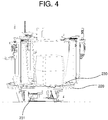
Fig. 4 is a drawing schematically illustrating a rotating sub-unit in accordance with one example embodiment of the present disclosure. -
Figs. 5A to 5C are drawings schematically illustrating a first robotic arm, a second robotic arm, and a third robotic arm, in accordance with one example embodiment of the present disclosure. -
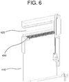
Fig. 6 is a drawing schematically illustrating a loading unit in accordance with one example embodiment of the present disclosure. - In the following detailed description, reference is made to the accompanying drawings that show, by way of illustration, specific embodiments in which the present disclosure may be practiced. These embodiments are described in sufficient detail to enable those skilled in the art to practice the present disclosure. It is to be understood that the various embodiments of the present disclosure, although different, are not necessarily mutually exclusive. For example, a particular feature, structure, or characteristic described herein in connection with one embodiment may be implemented within other embodiments without departing from the spirit and scope of the present disclosure.
- In addition, it is to be understood that the position or arrangement of individual elements within each disclosed embodiment may be modified without departing from the spirit and scope of the present disclosure. The following detailed description is, therefore, not to be taken in a limiting sense, and the scope of the present disclosure is defined only by the appended claims, appropriately interpreted, along with the full range of equivalents to which the claims are entitled. In the drawings, like numerals refer to the same or similar functionality throughout the several views.
- To allow those skilled in the art to carry out the present disclosure easily, the example embodiments of the present disclosure will be explained in detail by referring to attached diagrams as shown below.
-
Fig. 1 is a drawing schematically illustrating a construction robot for a ceiling in accordance with one example embodiment of the present disclosure. - By referring to
Fig. 1 , the construction robot may include arobot base 100, atargeting unit 200, arobotic arm assembly 300, and aloading unit 400. - First, the
robot base 100 may correspond to a lower part of the construction robot and may include anupper plate 110 which may be controlled to be elevated or lowered for anchor installation. - And, the
robot base 100 may further include ascissor lift 120 for elevating or lowering theupper plate 110, and thescissor lift 120 may be installed under theupper plate 110. But the scope of the present disclosure is not limited thereto. For example, thescissor lift 120 may be replaced with any device, e.g., a rack-and-pinion elevating device, a motor-driven elevating device, a hydraulic elevating device, etc., capable of elevating or lowering theupper plate 110. - Also, the
robot base 100 may further havemultiple wheels robot base 100 may move about at a workplace by using various ways of moving. - In addition, the
robot base 100 may further include a location fixing device to be used for fixing the construction robot at a certain location on the workplace. - Next, the
targeting unit 200 may include: afirst targeting sub-unit 210, asecond targeting sub-unit 220, and a rotatingsub-unit 230. The first targetingsub-unit 210 mounted on theupper plate 110 may be controlled to move along first directions corresponding to at least one first rack, serving as a first track, on theupper plate 110 according to information on the ceiling. Herein, the first directions may be directions of the positive or negative x-axis on a plane of theupper plate 110 as the case may be. The second targetingsub-unit 220 mounted on the first targetingsub-unit 210 may be controlled to move along second directions corresponding to at least one second rack, serving as a second track, on the first targetingsub-unit 210 according to the information on the ceiling. Herein, the second directions may be directions of the positive or negative y-axis on the plane of theupper plate 110 as the case may be. The rotatingsub-unit 230 mounted on the second targetingsub-unit 220 may be controlled to be positioned under a specific spot in the ceiling by being moved along the first directions and/or the second directions on theupper plate 110 and may be controlled to rotate about its own axis according to the information on the ceiling. - In detail, by referring to
Fig. 2 , afirst pinion 211 may be formed under the first targetingsub-unit 210 and may be engaged with thefirst rack 111 on theupper plate 110. Herein, thefirst pinion 211 may be driven by afirst servomotor 212 for horizontal movement. Therefore, the first targetingsub-unit 210 may be controlled to move along the first directions according to rotation of thefirst pinion 211. - Also, by referring to
Fig. 3 , asecond pinion 221 may be formed under the second targetingsub-unit 220 and may be engaged with thesecond rack 213 on the first targetingsub-unit 210. Herein, thesecond pinion 221 may be driven by asecond servomotor 222 for the horizontal movement. Therefore, the second targetingsub-unit 220 may be controlled to move along the second directions according to rotation of thesecond pinion 221. - Also, by referring to
Fig. 4 , the rotatingsub-unit 230 may be mounted on thesecond targeting sub-unit 220 and may be controlled to rotate about its own axis by athird servomotor 231 for the horizontal movement installed under the rotatingsub-unit 230. - Meanwhile, the first targeting
sub-unit 210, the second targetingsub-unit 220, and the rotatingsub-unit 230 are described above as being moved or rotated by using a rail track system with a rack-and-pinion mechanism, however, as another example, a driving and steering system, commonly used in AGVs (Automated Guided Vehicles), autonomous mobile robots, etc. for example, may be used for allowing the movement or the rotation in the workplace. - Next, the
robotic arm assembly 300 may include a firstrobotic arm 310, a secondrobotic arm 320, and a thirdrobotic arm 330. Herein, each of at least part of a first elevating unit of the firstrobotic arm 310, at least part of a second elevating unit of the secondrobotic arm 320, and at least part of a third elevating unit of the thirdrobotic arm 330 may be controlled to be elevated or lowered and may be combined with the rotatingsub-unit 230. - In detail, by referring to
Fig. 5A , the firstrobotic arm 310 may include (1) a firstarm supporting unit 311, combined with therotating sub-unit 230, among arm supporting units, (2) the first elevatingunit 312, combined with the firstarm supporting unit 311 and controlled to move toward or away from the ceiling, among elevating units, and (3) afirst servomotor 313 for vertical movement. Herein, the first elevatingunit 312 may be engaged with the firstarm supporting unit 311. And the first elevatingunit 312 may be controlled to elevate or lower adrill 314 mounted thereon. Further, thefirst servomotor 313 for the vertical movement may be combined with the firstarm supporting unit 311, and the at least part of the first elevatingunit 312 together with thedrill 314 may be controlled to be elevated or lowered by thefirst servomotor 313 for the vertical movement. Herein, thedrill 314 may include a driving unit (not shown) for driving thedrill 314. Also, the firstrobotic arm 310 may further include a dust capturing device (not shown) for capturing dust while thedrill 314 drills the hole into the ceiling. - Also, by referring to
Fig. 5B , the secondrobotic arm 320 may include (1) a secondarm supporting unit 321, combined with therotating sub-unit 230, among the arm supporting units, (2) the second elevatingunit 322, combined with the secondarm supporting unit 321 and controlled to move toward or away from the ceiling, among the elevating units, and (3) asecond servomotor 323 for the vertical movement. Herein, the second elevatingunit 322 may be engaged with the secondarm supporting unit 321. And the second elevatingunit 322 may be controlled to elevate or lower an anchorbolt inserting equipment 324 mounted thereon for inserting the anchor bolt into the hole. Further, thesecond servomotor 323 for the vertical movement may be combined with the secondarm supporting unit 321, and the at least part of the second elevatingunit 322 together with the anchorbolt inserting equipment 324 may be controlled to be elevated or lowered by thesecond servomotor 323 for the vertical movement. Herein, the anchorbolt inserting equipment 324 may include a driving unit (not shown) for driving the anchorbolt inserting equipment 324. Also, the secondrobotic arm 320 may further include a dust capturing device (not shown) for capturing dust while the anchorbolt inserting equipment 324 inserts the anchor bolt into the hole in the ceiling. - Also, by referring to
Fig. 5C , the thirdrobotic arm 330 may include (1) a thirdarm supporting unit 331, combined with therotating sub-unit 230, among the arm supporting units, (2) the third elevatingunit 332, combined with the thirdarm supporting unit 331 and controlled to move toward or away from the ceiling, among the elevating units, and (3) athird servomotor 333 for the vertical movement. Herein, the third elevatingunit 332 may be engaged with the thirdarm supporting unit 331. And the third elevatingunit 332 may be controlled to elevate or lower animpact wrench 334 mounted thereon for engaging the anchor nut with the anchor bolt and tightening the anchor nut. Further, thethird servomotor 333 for the vertical movement may be combined with the thirdarm supporting unit 331, and the at least part of the third elevatingunit 332 together with theimpact wrench 334 may be controlled to be elevated or lowered by thethird servomotor 333 for the vertical movement. Herein, theimpact wrench 334 may include a driving unit (not shown) for driving theimpact wrench 334. Also, the thirdrobotic arm 330 may further include a dust capturing device (not shown) for capturing dust while theimpact wrench 334 engages the anchor nut with the anchor bolt. - Meanwhile, each of the first
robotic arm 310, the secondrobotic arm 320, and thethird robot arm 330, respectively combined with therotating sub-unit 230, may be controlled to move along a same trajectory when therotating sub-unit 230 is controlled to rotate about its own axis. - That is, due to rotation of the
rotating sub-unit 230 about its own axis, each of the firstrobotic arm 310, the secondrobotic arm 320, and the thirdrobotic arm 330 may be controlled to be positioned under a same location on the ceiling, to thereby drill the hole, insert the anchor bolt into the hole, and tighten the anchor nut engaged with the anchor bolt, all under the same location on the ceiling. - Also, due only to the rotation of the
rotating sub-unit 230, a process of inserting the anchor into the ceiling may be performed by using the firstrobotic arm 310, the secondrobotic arm 320, and the thirdrobotic arm 330 interchangeably, even in a tight space. - Meanwhile, each of the first
robotic arm 310, the secondrobotic arm 320, and the thirdrobotic arm 330 is described above as comprised of its corresponding arm supporting unit, its corresponding elevating unit, and its corresponding servomotor for the vertical movement. However, as another example, each of the firstrobotic arm 310, the secondrobotic arm 320, and the thirdrobotic arm 330 may be an articulated robotic arm. - Next, the
loading unit 400 may be mounted on at least one of theupper plate 110, the first targetingsub-unit 210, and thesecond targeting sub-unit 220. And theloading unit 400 may be controlled to provide one or moreanchor bolt assemblies 430, each of which is created by engaging the anchor bolt with the anchor nut. - Specifically, by referring to
Fig. 6 , theloading unit 400 may include (1) at least oneload supporting unit 410 mounted on at least one of theupper plate 110, the first targetingsub-unit 210, and thesecond targeting sub-unit 220 and (2) an anchorassembly supplying unit 420, on which theanchor bolt assemblies 430 are to be loaded, combined with theload supporting unit 410 and controlled to move toward or away from therobotic arm assembly 300. - Meanwhile, a plurality of leveling
units upper plate 110 movably toward or away from the ceiling. The levelingunits upper plate 110 to be leveled by making contact with the ceiling. Herein, each of the levelingunits - Further, each of the leveling
units - Also, each of the leveling
units upper plate 110 is leveled against the ceiling, or as another example, each of the levelingunits upper plate 110 is leveled against a horizontal plane. - Processes of the anchor installation at the workplace by using the construction robot for the ceiling configured as above in accordance with one example embodiment of the present disclosure are described as follows.
- First, the construction robot may be controlled to transport itself to a predetermined location under the specific spot in the ceiling at the workplace by operating the
robot base 100. Herein, after moving to the predetermined location, therobot base 100 may prevent the construction robot from being moved out of the predetermined location, by using the location fixing device. - Also, the construction robot may be controlled to elevate the leveling
units upper plate 110, to thereby allow theleveling units upper plate 110 to be leveled. Herein, although the process of leveling theupper plate 110 is described as being performed before processes of adjusting the first targetingsub-unit 210, thesecond targeting sub-unit 220, and therotating sub-unit 230 described below, the scope of the present disclosure is not limited thereto, and the process of leveling theupper plate 110 may be performed at any step after the process of fixing the construction robot at the predetermined location under the specific spot and before the process of drilling the hole on the specific spot. - And, the first targeting sub-unit 210 may be controlled to move on the
upper plate 110 toward theloading unit 400 along the first directions, then thesecond targeting sub-unit 220 may be controlled to move along the second directions so that the thirdrobotic arm 330 is allowed to be positioned near theloading unit 400 if therotating sub-unit 230 is rotated, and therotating sub-unit 230 may be controlled to rotate about its own axis so that the thirdrobotic arm 330 is positioned near theloading unit 400. Herein, if the thirdrobotic arm 330 is positioned near theloading unit 400, theimpact wrench 334 may be controlled to loosen and disengage the anchor nut from one of the anchor bolt assemblies loaded on theloading unit 400 and may be controlled to hold the disengaged anchor nut. - Herein, the at least part of the third elevating unit of the third
robotic arm 330 may be controlled to move toward theloading unit 400, then theimpact wrench 334 may be controlled to disengage and hold the anchor nut, and the at least part of the third elevating unit may be controlled to move away from theloading unit 400. - As another example, the
loading unit 400 may be controlled to move toward theimpact wrench 334, then theimpact wrench 334 may be controlled to disengage and hold the anchor nut, and theloading unit 400 may be controlled to move away from theimpact wrench 334. - Next, while the disengaged anchor nut is held by the
impact wrench 334, therotating sub-unit 230 may be controlled to rotate about its own axis so that the secondrobotic arm 320 is positioned near theloading unit 400. Then, the anchorbolt inserting equipment 324 may be provided with the anchor bolt from which the anchor nut is disengaged. - Herein, the at least part of the second elevating unit of the second
robotic arm 320 may be controlled to move toward theloading unit 400, and the anchorbolt inserting equipment 324 may be provided with the anchor bolt, from which the anchor nut is disengaged, loaded on theloading unit 400, then the at least part of the second elevating unit may be controlled to move away from theloading unit 400. - As another example, the
loading unit 400 may be controlled to move toward the anchorbolt inserting equipment 324, and the anchorbolt inserting equipment 324 may be provided with the anchor bolt, from which the anchor nut is disengaged, loaded on theloading unit 400, then theloading unit 400 may be controlled to move away from the anchorbolt inserting equipment 324. - Next, the targeting
unit 200 may be controlled to move to the specific spot in the ceiling, so that the firstrobotic arm 310 may be positioned under the specific spot in the ceiling for the anchor installation. Herein, if the firstrobotic arm 310 is positioned under the specific spot, the at least part of the first elevating unit of the firstrobotic arm 310 may be controlled to be elevated, to thereby allow thedrill 314 to drill the hole on the specific spot, and then may be controlled to be lowered. - Next, if the hole is drilled on the specific spot, the
rotating sub-unit 230 may be controlled to rotate about its own axis so that the secondrobotic arm 320 is positioned under the specific spot. Herein, if the secondrobotic arm 320 is positioned under the specific spot, the at least part of the second elevating unit of the secondrobotic arm 320 may be controlled to be elevated, to thereby allow the anchorbolt inserting equipment 324 to insert the anchor bolt into the hole on the specific spot, and then may be controlled to be lowered. Herein, after inserting the anchor bolt into the hole, the anchorbolt inserting equipment 324 may be controlled to fix the anchor bolt in the hole by punching operation. - Next, if the anchor bolt is inserted into the hole, the
rotating sub-unit 230 may be controlled to rotate about its own axis so that the thirdrobotic arm 330 is positioned under the specific spot. Herein, if the thirdrobotic arm 330 is positioned under the specific spot, the at least part of the third elevating unit of the thirdrobotic arm 330 may be controlled to be elevated, to thereby allow theimpact wrench 334 to engage the anchor nut with the anchor bolt inserted into the hole on the specific spot, and then may be controlled to be lowered. - The present disclosure has an effect of reducing time consumed for inserting the anchors into the ceiling by using a method and a structure for controlling the drill for drilling the hole, the anchor bolt inserting equipment for inserting the anchor bolt into the hole, and the impact wrench for tightening the anchor nut engaged with the inserted anchor bolt.
- The present disclosure has another effect of allowing the anchor installation even in the tight space by using the drill, the anchor bolt inserting equipment, and the impact wrench interchangeably due to the rotation of the rotating sub-unit on which the drill, the anchor bolt inserting equipment, and the impact wrench are mounted.
- The present disclosure has still another effect of allowing each of the drill, the anchor bolt inserting equipment, and the impact wrench to be positioned at a same spot on the ceiling by the rotation of the rotating sub-unit alone.
- The present disclosure has still yet another effect of allowing the anchor bolt and the anchor nut to be automatically provided by using the loading unit.
- The present disclosure has still yet another effect of allowing the upper plate to be leveled by using the plurality of the leveling units.
- As seen above, the present disclosure has been explained by specific matters such as detailed components, limited embodiments, and drawings. They have been provided only to help more general understanding of the present disclosure. It, however, will be understood by those skilled in the art that various changes and modification may be made from the description without departing from the spirit and scope of the disclosure as defined in the following claims.
- Accordingly, the spirit of the present disclosure must not be confined to the explained embodiments, and the following patent claims as well as everything including variations equal or equivalent to the patent claims pertain to the category of the spirit of the present disclosure.
Claims (9)
- A construction robot for a ceiling, comprising:a robot base including an upper plate, wherein the upper plate is controlled to be elevated or lowered for anchor installation;a targeting unit mounted on the upper plate, wherein the targeting unit is controlled to move a robotic arm assembly for the anchor installation, andwherein the robotic arm assembly includes:a first robotic arm, combined with the targeting unit, on which a drill for drilling a hole into the ceiling is mounted, wherein at least part of a first elevating unit of the first robotic arm is controlled to be elevated or lowered according to information on the ceiling,a second robotic arm, combined with the targeting unit, on which an anchor bolt inserting equipment for inserting at least one anchor bolt into the hole is mounted, wherein at least part of a second elevating unit of the second robotic arm is controlled to be elevated or lowered according to the information on the ceiling, anda third robotic arm, combined with the targeting unit, on which an impact wrench for tightening the anchor bolt by engaging at least one anchor nut with the anchor bolt is mounted, wherein at least part of a third elevating unit of the third robotic arm is controlled to be elevated or lowered according to the information on the ceiling; anda loading unit, mounted on at least one of the upper plate and the targeting unit, for providing one or more anchor bolt assemblies, each of which is created by engaging the anchor bolt with the anchor nut.
- The construction robot of Claim 1, wherein each of the first robotic arm, the second robotic arm, and the third robotic arm, respectively combined with a rotating sub-unit in the targeting unit, is controlled to move along a same trajectory when the rotating sub-unit is controlled to rotate about its own axis.
- The construction robot of Claim 1, wherein each of the first robotic arm, the second robotic arm, and the third robotic arm includes (1) its corresponding each of arm supporting units combined with a rotating sub-unit in the targeting unit and (2) its corresponding each of elevating units engaged with each of the arm supporting units and wherein at least part of each of the elevating units, driven by each of servomotors for vertical movement combined with each of the arm supporting units, is controlled to be elevated or lowered.
- The construction robot of Claim 1, wherein the targeting unit includes: a first targeting sub-unit mounted on the upper plate wherein the first targeting sub-unit is controlled to move along first directions corresponding to at least one first rack, serving as a first track, on the upper plate according to the information on the ceiling; a second targeting sub-unit mounted on the first targeting sub-unit wherein the second targeting sub-unit is controlled to move along second directions corresponding to at least one second rack, serving as a second track, on the first targeting sub-unit according to the information on the ceiling; and a rotating sub-unit mounted on the second targeting sub-unit wherein the rotating sub-unit is controlled to rotate about its own axis according to the information on the ceiling.
- The construction robot of Claim 4, wherein, while a first pinion formed under the first targeting sub-unit is engaged with the first rack, the first targeting sub-unit is controlled to move along the first directions according to rotation of the first pinion driven by a first servomotor for horizontal movement, wherein, while a second pinion formed under the second targeting sub-unit is engaged with the second rack, the second targeting sub-unit is controlled to move along the second directions according to rotation of the second pinion driven by a second servomotor for the horizontal movement, and wherein the rotating sub-unit is controlled to rotate about its own axis by a third servomotor for the horizontal movement.
- The construction robot of Claim 1, wherein the loading unit includes (1) at least one load supporting unit mounted on at least one of the upper plate and the targeting unit and (2) an anchor assembly supplying unit, on which the anchor bolt assemblies are to be loaded, combined with the load supporting unit movably toward or away from the robotic arm assembly.
- The construction robot of Claim 1, further comprising a plurality of leveling units mounted on the upper plate movably toward or away from the ceiling and wherein the leveling units allow the upper plate to be leveled by making contact with the ceiling.
- The construction robot of Claim 1, wherein the upper plate is mounted on the robot base and wherein the robot base includes a scissor lift which is controlled to elevate or lower the upper plate.
- The construction robot of Claim 1, wherein (i) the targeting unit is controlled to move toward the loading unit and then the rotating sub-unit is controlled to rotate about its own axis so that the third robotic arm is positioned near the loading unit, to thereby allow the impact wrench to loosen and disengage the anchor nut from one of the anchor bolt assemblies loaded on the loading unit and thus to hold the disengaged anchor nut, (ii) the rotating sub-unit is controlled to rotate about its own axis while the disengaged anchor nut is held by the impact wrench so that the second robotic arm is positioned near the loading unit, to thereby allow the anchor bolt inserting equipment to be provided with the anchor bolt, (iii) while the at least part of the first elevating unit of the first robotic arm is controlled to be elevated or lowered, the targeting unit is controlled to move to a specific spot in the ceiling and then the rotating sub-unit is controlled to rotate about its own axis so that the first robotic arm is positioned under the specific spot in the ceiling, to thereby allow the drill to drill the hole on the specific spot, (iv) while the at least part of the second elevating unit of the second robotic arm is controlled to be elevated or lowered, the rotating sub-unit is controlled to rotate about its own axis so that the second robotic arm is positioned under the specific spot, to thereby allow the anchor bolt inserting equipment to insert the anchor bolt into the hole, and (v) while the at least part of the third elevating unit of the third robotic arm is controlled to be elevated or lowered, the rotating sub-unit is controlled to rotate about its own axis so that the third robotic arm is positioned under the specific spot, to thereby allow the impact wrench to engage the anchor nut with the anchor bolt inserted into the hole and to tighten the anchor nut.
Applications Claiming Priority (1)
| Application Number | Priority Date | Filing Date | Title |
|---|---|---|---|
| KR1020200002294A KR102115219B1 (en) | 2020-01-07 | 2020-01-07 | Construction robot for ceiling |
Publications (2)
| Publication Number | Publication Date |
|---|---|
| EP3848166A1 true EP3848166A1 (en) | 2021-07-14 |
| EP3848166B1 EP3848166B1 (en) | 2022-10-26 |
Family
ID=70910823
Family Applications (1)
| Application Number | Title | Priority Date | Filing Date |
|---|---|---|---|
| EP20203833.7A Active EP3848166B1 (en) | 2020-01-07 | 2020-10-26 | Construction robot for ceiling |
Country Status (4)
| Country | Link |
|---|---|
| US (1) | US11364639B2 (en) |
| EP (1) | EP3848166B1 (en) |
| KR (1) | KR102115219B1 (en) |
| CN (1) | CN113146645B (en) |
Cited By (2)
| Publication number | Priority date | Publication date | Assignee | Title |
|---|---|---|---|---|
| EP4279221A1 (en) * | 2022-05-19 | 2023-11-22 | Hilti Aktiengesellschaft | Construction robot with parallel manipulator |
| EP4368352A1 (en) | 2022-11-14 | 2024-05-15 | Baubot GmbH | Mobile construction robot |
Families Citing this family (17)
| Publication number | Priority date | Publication date | Assignee | Title |
|---|---|---|---|---|
| US11890737B2 (en) * | 2015-12-28 | 2024-02-06 | Peter Justin Merello | Overhead drill and anchor press |
| KR20200001278U (en) * | 2020-05-28 | 2020-06-17 | 문춘호 | Punching apparatus |
| CN111926972B (en) * | 2020-08-11 | 2021-05-28 | 东莞市裕永建筑工程有限公司 | Method for installing prefabricated composite floor slab of prefabricated building |
| KR200495184Y1 (en) * | 2020-08-14 | 2022-03-24 | 문춘호 | Punching apparatus |
| JP2024505163A (en) * | 2021-02-01 | 2024-02-05 | アーベーベー・シュバイツ・アーゲー | Assemblies, devices and methods for machining mechanical parts |
| CN112983018B (en) * | 2021-02-05 | 2024-04-05 | 保利长大海外工程有限公司 | Construction equipment for installing fastener on building surface |
| KR102289513B1 (en) * | 2021-03-18 | 2021-08-17 | 대명지이씨(주) | Construction robot for installing anchor on the ceiling |
| CN115722907A (en) * | 2021-08-25 | 2023-03-03 | 广东博智林机器人有限公司 | Boom mounting system and expansion bolt mounting device |
| CN116065837A (en) * | 2021-10-29 | 2023-05-05 | 广东博智林机器人有限公司 | Boom installation equipment and boom installation method |
| CN115215261A (en) * | 2022-07-18 | 2022-10-21 | 杭州申昊科技股份有限公司 | Jacking mechanism for lifting and descending robot |
| KR102745289B1 (en) * | 2022-11-14 | 2024-12-23 | 하이시스 주식회사 | Device for lifting robot in robot-based hybrid construction 3d printer |
| CN116969399A (en) * | 2023-09-25 | 2023-10-31 | 泰安万川电器设备有限公司 | Track beam lifting installation equipment |
| CN117600817A (en) * | 2023-11-20 | 2024-02-27 | 迈特诺(马鞍山)特种电缆有限公司 | An intelligent assembly car for electric wrenches |
| CN117564637A (en) * | 2023-11-24 | 2024-02-20 | 广州市城市建设开发有限公司 | An automatic installation robot for TOD building noise reduction/sound-absorbing ceiling dampers |
| WO2025216381A1 (en) * | 2024-04-08 | 2025-10-16 | 엠에프알 주식회사 | Robot for automatically installing fireproof panels and method for installing fireproof panels by using same |
| CN118241842B (en) * | 2024-05-29 | 2024-07-26 | 山西三建集团有限公司 | Leveling device for building construction |
| CN119388589B (en) * | 2024-11-28 | 2025-10-31 | 合肥工业大学 | Intelligent mounting equipment for lamp and control method thereof |
Citations (9)
| Publication number | Priority date | Publication date | Assignee | Title |
|---|---|---|---|---|
| JPS4942127A (en) * | 1972-08-29 | 1974-04-20 | ||
| JPH06200628A (en) * | 1992-12-29 | 1994-07-19 | Toshiba Eng & Constr Co Ltd | Anchor driving device in surface of ceiling or bottom of beam |
| JPH1054142A (en) * | 1996-08-09 | 1998-02-24 | Takasago Thermal Eng Co Ltd | Anchor pin setting device |
| JPH1054143A (en) * | 1996-08-12 | 1998-02-24 | Takasago Thermal Eng Co Ltd | Anchor mounting device |
| KR20120132814A (en) * | 2011-05-30 | 2012-12-10 | 대명지이씨(주) | Ceiling anchor construction device |
| KR101381958B1 (en) | 2012-07-23 | 2014-04-07 | 허광학 | an installing apparatus of anchor to ceiling |
| WO2016066615A2 (en) * | 2014-10-28 | 2016-05-06 | Nlink As | Mobile robotic drilling apparatus and method for drilling ceilings and walls |
| KR20170014700A (en) | 2015-07-31 | 2017-02-08 | 김용기 | drill for ceiling anchor |
| US10480319B2 (en) * | 2016-09-22 | 2019-11-19 | Bouygues Travaux Publics | Automated device for drilling a hole in the vault and walls of a tunnel and for installing an anchoring element into said hole |
Family Cites Families (12)
| Publication number | Priority date | Publication date | Assignee | Title |
|---|---|---|---|---|
| JP2808018B2 (en) * | 1989-09-08 | 1998-10-08 | 東急建設株式会社 | Robots for interior construction |
| JP3019871B2 (en) * | 1990-11-01 | 2000-03-13 | 日本ベンチャー工業株式会社 | Ceiling construction robot and ceiling construction method |
| KR20150010428A (en) * | 2013-07-19 | 2015-01-28 | 현대중공업 주식회사 | Apparatus and Method for Removing Valve Guide |
| CN204343979U (en) * | 2014-11-18 | 2015-05-20 | 张斌 | The robot that building ceiling punches |
| KR101774954B1 (en) * | 2015-12-14 | 2017-09-26 | 에프엠글로벌 주식회사 | Device for mending inside wall of blast furnace |
| KR101835265B1 (en) * | 2016-07-01 | 2018-03-08 | 최태원 | apparatus for drilling on the ceil |
| CN106703689B (en) * | 2016-12-10 | 2020-06-05 | 中国铁建电气化局集团北方工程有限公司 | Automatic punching device and method for high-speed rail tunnel anchor bolt implantation |
| CN107932052B (en) * | 2017-12-29 | 2023-12-01 | 深圳时代装饰股份有限公司 | Device for facilitating the perforation of ceilings and the installation of expansion bolts |
| CN110394702A (en) * | 2019-08-21 | 2019-11-01 | 广东博智林机器人有限公司 | A kind of ceiling grinding device and the ceiling grinder device people using the device |
| AU2020102623A4 (en) * | 2019-10-11 | 2020-11-26 | Salunke, Nagabhushan MR | "Apparatus, System and Method for actuating a Tool" |
| CN110587632B (en) * | 2019-10-22 | 2024-05-03 | 东莞美崎智能科技有限公司 | Full-automatic locating drilling and explosion-pulling screw installation integrated machine |
| KR102217247B1 (en) * | 2020-06-08 | 2021-02-18 | 주식회사 지오시스템 | smart drilling machine, smart drilling system and a control method of the same |
-
2020
- 2020-01-07 KR KR1020200002294A patent/KR102115219B1/en active Active
- 2020-10-26 EP EP20203833.7A patent/EP3848166B1/en active Active
- 2020-11-20 US US16/953,685 patent/US11364639B2/en active Active
-
2021
- 2021-01-06 CN CN202110012465.9A patent/CN113146645B/en active Active
Patent Citations (9)
| Publication number | Priority date | Publication date | Assignee | Title |
|---|---|---|---|---|
| JPS4942127A (en) * | 1972-08-29 | 1974-04-20 | ||
| JPH06200628A (en) * | 1992-12-29 | 1994-07-19 | Toshiba Eng & Constr Co Ltd | Anchor driving device in surface of ceiling or bottom of beam |
| JPH1054142A (en) * | 1996-08-09 | 1998-02-24 | Takasago Thermal Eng Co Ltd | Anchor pin setting device |
| JPH1054143A (en) * | 1996-08-12 | 1998-02-24 | Takasago Thermal Eng Co Ltd | Anchor mounting device |
| KR20120132814A (en) * | 2011-05-30 | 2012-12-10 | 대명지이씨(주) | Ceiling anchor construction device |
| KR101381958B1 (en) | 2012-07-23 | 2014-04-07 | 허광학 | an installing apparatus of anchor to ceiling |
| WO2016066615A2 (en) * | 2014-10-28 | 2016-05-06 | Nlink As | Mobile robotic drilling apparatus and method for drilling ceilings and walls |
| KR20170014700A (en) | 2015-07-31 | 2017-02-08 | 김용기 | drill for ceiling anchor |
| US10480319B2 (en) * | 2016-09-22 | 2019-11-19 | Bouygues Travaux Publics | Automated device for drilling a hole in the vault and walls of a tunnel and for installing an anchoring element into said hole |
Cited By (4)
| Publication number | Priority date | Publication date | Assignee | Title |
|---|---|---|---|---|
| EP4279221A1 (en) * | 2022-05-19 | 2023-11-22 | Hilti Aktiengesellschaft | Construction robot with parallel manipulator |
| WO2023222436A1 (en) * | 2022-05-19 | 2023-11-23 | Hilti Aktiengesellschaft | Construction robot having parallel manipulator |
| EP4368352A1 (en) | 2022-11-14 | 2024-05-15 | Baubot GmbH | Mobile construction robot |
| WO2024104995A1 (en) | 2022-11-14 | 2024-05-23 | Baubot Gmbh | Mobile construction robot |
Also Published As
| Publication number | Publication date |
|---|---|
| US20210205998A1 (en) | 2021-07-08 |
| US11364639B2 (en) | 2022-06-21 |
| CN113146645A (en) | 2021-07-23 |
| CN113146645B (en) | 2024-05-17 |
| KR102115219B1 (en) | 2020-05-27 |
| EP3848166B1 (en) | 2022-10-26 |
Similar Documents
| Publication | Publication Date | Title |
|---|---|---|
| EP3848166B1 (en) | Construction robot for ceiling | |
| US10850946B2 (en) | Automated mounting device for performing assembly jobs in an elevator shaft of an elevator system | |
| JP2935808B2 (en) | Ceiling and wall interior construction equipment and its accessories | |
| KR102289513B1 (en) | Construction robot for installing anchor on the ceiling | |
| CN109676592B (en) | Automatic assembling method and automatic assembling equipment | |
| KR20000073586A (en) | Auto welding system for recycling engine block | |
| JP2023504631A5 (en) | ||
| CN111844129B (en) | Robot maintenance device and robot maintenance method | |
| CN115193655A (en) | Component assembly system for automated production lines | |
| US12053880B2 (en) | Mobile robot platform | |
| US20180141052A1 (en) | Suspension and Guidance Apparatus for Tools and Platforms Relative to A Mill | |
| JP7072489B2 (en) | Welding equipment and welding method | |
| KR20110085865A (en) | Robot system and positioner with positioner | |
| CN215393295U (en) | Robot unilateral overturning welding workstation for hydraulic support structural part | |
| CN207858092U (en) | A kind of kart assembling mechanical arm | |
| WO2021095169A1 (en) | Battery installation system and battery installation method | |
| JP2016193484A (en) | Automatic assembly apparatus and automatic assembly method | |
| CN219403537U (en) | Drilling device for numerical control machining center | |
| CN214784771U (en) | Nomadic type prefabricated part machining device | |
| KR102916815B1 (en) | Automatic Bolt Fastening Device | |
| CN222511453U (en) | Welding device | |
| JP2666586B2 (en) | How to stop a broken robot | |
| KR20250105555A (en) | Projection Welding System | |
| JPS61241078A (en) | work robot | |
| WO2023248060A8 (en) | Method for carrying out industrial working operations within a work environment, and related system |
Legal Events
| Date | Code | Title | Description |
|---|---|---|---|
| PUAI | Public reference made under article 153(3) epc to a published international application that has entered the european phase |
Free format text: ORIGINAL CODE: 0009012 |
|
| STAA | Information on the status of an ep patent application or granted ep patent |
Free format text: STATUS: REQUEST FOR EXAMINATION WAS MADE |
|
| 17P | Request for examination filed |
Effective date: 20201026 |
|
| AK | Designated contracting states |
Kind code of ref document: A1 Designated state(s): AL AT BE BG CH CY CZ DE DK EE ES FI FR GB GR HR HU IE IS IT LI LT LU LV MC MK MT NL NO PL PT RO RS SE SI SK SM TR |
|
| RBV | Designated contracting states (corrected) |
Designated state(s): AL AT BE BG CH CY CZ DE DK EE ES FI FR GB GR HR HU IE IS IT LI LT LU LV MC MK MT NL NO PL PT RO RS SE SI SK SM TR |
|
| RIC1 | Information provided on ipc code assigned before grant |
Ipc: E21D 20/00 20060101ALI20220331BHEP Ipc: E04G 21/16 20060101ALI20220331BHEP Ipc: B28D 1/14 20060101ALI20220331BHEP Ipc: B25B 21/02 20060101ALI20220331BHEP Ipc: B66F 7/06 20060101ALI20220331BHEP Ipc: B25H 1/00 20060101ALI20220331BHEP Ipc: B25J 11/00 20060101AFI20220331BHEP |
|
| GRAP | Despatch of communication of intention to grant a patent |
Free format text: ORIGINAL CODE: EPIDOSNIGR1 |
|
| STAA | Information on the status of an ep patent application or granted ep patent |
Free format text: STATUS: GRANT OF PATENT IS INTENDED |
|
| INTG | Intention to grant announced |
Effective date: 20220531 |
|
| RIN1 | Information on inventor provided before grant (corrected) |
Inventor name: KIM, CHUL YOUNG Inventor name: LEE, KYE YOUNG Inventor name: PARK, CHUN WON Inventor name: JUN, YOUNG WOON Inventor name: JI, JUNG HWAN Inventor name: LEE, SUNG HU Inventor name: SEO, JONG MAN |
|
| GRAS | Grant fee paid |
Free format text: ORIGINAL CODE: EPIDOSNIGR3 |
|
| GRAA | (expected) grant |
Free format text: ORIGINAL CODE: 0009210 |
|
| STAA | Information on the status of an ep patent application or granted ep patent |
Free format text: STATUS: THE PATENT HAS BEEN GRANTED |
|
| AK | Designated contracting states |
Kind code of ref document: B1 Designated state(s): AL AT BE BG CH CY CZ DE DK EE ES FI FR GB GR HR HU IE IS IT LI LT LU LV MC MK MT NL NO PL PT RO RS SE SI SK SM TR |
|
| REG | Reference to a national code |
Ref country code: GB Ref legal event code: FG4D |
|
| REG | Reference to a national code |
Ref country code: CH Ref legal event code: EP |
|
| REG | Reference to a national code |
Ref country code: AT Ref legal event code: REF Ref document number: 1526730 Country of ref document: AT Kind code of ref document: T Effective date: 20221115 |
|
| REG | Reference to a national code |
Ref country code: DE Ref legal event code: R096 Ref document number: 602020005861 Country of ref document: DE |
|
| REG | Reference to a national code |
Ref country code: IE Ref legal event code: FG4D |
|
| REG | Reference to a national code |
Ref country code: LT Ref legal event code: MG9D |
|
| REG | Reference to a national code |
Ref country code: NL Ref legal event code: MP Effective date: 20221026 |
|
| REG | Reference to a national code |
Ref country code: AT Ref legal event code: MK05 Ref document number: 1526730 Country of ref document: AT Kind code of ref document: T Effective date: 20221026 |
|
| PG25 | Lapsed in a contracting state [announced via postgrant information from national office to epo] |
Ref country code: NL Free format text: LAPSE BECAUSE OF FAILURE TO SUBMIT A TRANSLATION OF THE DESCRIPTION OR TO PAY THE FEE WITHIN THE PRESCRIBED TIME-LIMIT Effective date: 20221026 |
|
| PG25 | Lapsed in a contracting state [announced via postgrant information from national office to epo] |
Ref country code: SE Free format text: LAPSE BECAUSE OF FAILURE TO SUBMIT A TRANSLATION OF THE DESCRIPTION OR TO PAY THE FEE WITHIN THE PRESCRIBED TIME-LIMIT Effective date: 20221026 Ref country code: PT Free format text: LAPSE BECAUSE OF FAILURE TO SUBMIT A TRANSLATION OF THE DESCRIPTION OR TO PAY THE FEE WITHIN THE PRESCRIBED TIME-LIMIT Effective date: 20230227 Ref country code: NO Free format text: LAPSE BECAUSE OF FAILURE TO SUBMIT A TRANSLATION OF THE DESCRIPTION OR TO PAY THE FEE WITHIN THE PRESCRIBED TIME-LIMIT Effective date: 20230126 Ref country code: LT Free format text: LAPSE BECAUSE OF FAILURE TO SUBMIT A TRANSLATION OF THE DESCRIPTION OR TO PAY THE FEE WITHIN THE PRESCRIBED TIME-LIMIT Effective date: 20221026 Ref country code: FI Free format text: LAPSE BECAUSE OF FAILURE TO SUBMIT A TRANSLATION OF THE DESCRIPTION OR TO PAY THE FEE WITHIN THE PRESCRIBED TIME-LIMIT Effective date: 20221026 Ref country code: ES Free format text: LAPSE BECAUSE OF FAILURE TO SUBMIT A TRANSLATION OF THE DESCRIPTION OR TO PAY THE FEE WITHIN THE PRESCRIBED TIME-LIMIT Effective date: 20221026 Ref country code: AT Free format text: LAPSE BECAUSE OF FAILURE TO SUBMIT A TRANSLATION OF THE DESCRIPTION OR TO PAY THE FEE WITHIN THE PRESCRIBED TIME-LIMIT Effective date: 20221026 |
|
| REG | Reference to a national code |
Ref country code: DE Ref legal event code: R119 Ref document number: 602020005861 Country of ref document: DE |
|
| PG25 | Lapsed in a contracting state [announced via postgrant information from national office to epo] |
Ref country code: RS Free format text: LAPSE BECAUSE OF FAILURE TO SUBMIT A TRANSLATION OF THE DESCRIPTION OR TO PAY THE FEE WITHIN THE PRESCRIBED TIME-LIMIT Effective date: 20221026 Ref country code: PL Free format text: LAPSE BECAUSE OF FAILURE TO SUBMIT A TRANSLATION OF THE DESCRIPTION OR TO PAY THE FEE WITHIN THE PRESCRIBED TIME-LIMIT Effective date: 20221026 Ref country code: LV Free format text: LAPSE BECAUSE OF FAILURE TO SUBMIT A TRANSLATION OF THE DESCRIPTION OR TO PAY THE FEE WITHIN THE PRESCRIBED TIME-LIMIT Effective date: 20221026 Ref country code: IS Free format text: LAPSE BECAUSE OF FAILURE TO SUBMIT A TRANSLATION OF THE DESCRIPTION OR TO PAY THE FEE WITHIN THE PRESCRIBED TIME-LIMIT Effective date: 20230226 Ref country code: HR Free format text: LAPSE BECAUSE OF FAILURE TO SUBMIT A TRANSLATION OF THE DESCRIPTION OR TO PAY THE FEE WITHIN THE PRESCRIBED TIME-LIMIT Effective date: 20221026 Ref country code: GR Free format text: LAPSE BECAUSE OF FAILURE TO SUBMIT A TRANSLATION OF THE DESCRIPTION OR TO PAY THE FEE WITHIN THE PRESCRIBED TIME-LIMIT Effective date: 20230127 |
|
| REG | Reference to a national code |
Ref country code: BE Ref legal event code: MM Effective date: 20221031 |
|
| PG25 | Lapsed in a contracting state [announced via postgrant information from national office to epo] |
Ref country code: LU Free format text: LAPSE BECAUSE OF NON-PAYMENT OF DUE FEES Effective date: 20221026 |
|
| PG25 | Lapsed in a contracting state [announced via postgrant information from national office to epo] |
Ref country code: SM Free format text: LAPSE BECAUSE OF FAILURE TO SUBMIT A TRANSLATION OF THE DESCRIPTION OR TO PAY THE FEE WITHIN THE PRESCRIBED TIME-LIMIT Effective date: 20221026 Ref country code: RO Free format text: LAPSE BECAUSE OF FAILURE TO SUBMIT A TRANSLATION OF THE DESCRIPTION OR TO PAY THE FEE WITHIN THE PRESCRIBED TIME-LIMIT Effective date: 20221026 Ref country code: MC Free format text: LAPSE BECAUSE OF FAILURE TO SUBMIT A TRANSLATION OF THE DESCRIPTION OR TO PAY THE FEE WITHIN THE PRESCRIBED TIME-LIMIT Effective date: 20221026 Ref country code: EE Free format text: LAPSE BECAUSE OF FAILURE TO SUBMIT A TRANSLATION OF THE DESCRIPTION OR TO PAY THE FEE WITHIN THE PRESCRIBED TIME-LIMIT Effective date: 20221026 Ref country code: DK Free format text: LAPSE BECAUSE OF FAILURE TO SUBMIT A TRANSLATION OF THE DESCRIPTION OR TO PAY THE FEE WITHIN THE PRESCRIBED TIME-LIMIT Effective date: 20221026 Ref country code: DE Free format text: LAPSE BECAUSE OF NON-PAYMENT OF DUE FEES Effective date: 20230503 Ref country code: CZ Free format text: LAPSE BECAUSE OF FAILURE TO SUBMIT A TRANSLATION OF THE DESCRIPTION OR TO PAY THE FEE WITHIN THE PRESCRIBED TIME-LIMIT Effective date: 20221026 |
|
| PG25 | Lapsed in a contracting state [announced via postgrant information from national office to epo] |
Ref country code: SK Free format text: LAPSE BECAUSE OF FAILURE TO SUBMIT A TRANSLATION OF THE DESCRIPTION OR TO PAY THE FEE WITHIN THE PRESCRIBED TIME-LIMIT Effective date: 20221026 Ref country code: AL Free format text: LAPSE BECAUSE OF FAILURE TO SUBMIT A TRANSLATION OF THE DESCRIPTION OR TO PAY THE FEE WITHIN THE PRESCRIBED TIME-LIMIT Effective date: 20221026 |
|
| PLBE | No opposition filed within time limit |
Free format text: ORIGINAL CODE: 0009261 |
|
| STAA | Information on the status of an ep patent application or granted ep patent |
Free format text: STATUS: NO OPPOSITION FILED WITHIN TIME LIMIT |
|
| PG25 | Lapsed in a contracting state [announced via postgrant information from national office to epo] |
Ref country code: BE Free format text: LAPSE BECAUSE OF NON-PAYMENT OF DUE FEES Effective date: 20221031 |
|
| 26N | No opposition filed |
Effective date: 20230727 |
|
| PG25 | Lapsed in a contracting state [announced via postgrant information from national office to epo] |
Ref country code: IE Free format text: LAPSE BECAUSE OF NON-PAYMENT OF DUE FEES Effective date: 20221026 |
|
| PG25 | Lapsed in a contracting state [announced via postgrant information from national office to epo] |
Ref country code: SI Free format text: LAPSE BECAUSE OF FAILURE TO SUBMIT A TRANSLATION OF THE DESCRIPTION OR TO PAY THE FEE WITHIN THE PRESCRIBED TIME-LIMIT Effective date: 20221026 Ref country code: FR Free format text: LAPSE BECAUSE OF NON-PAYMENT OF DUE FEES Effective date: 20221226 |
|
| PG25 | Lapsed in a contracting state [announced via postgrant information from national office to epo] |
Ref country code: CY Free format text: LAPSE BECAUSE OF FAILURE TO SUBMIT A TRANSLATION OF THE DESCRIPTION OR TO PAY THE FEE WITHIN THE PRESCRIBED TIME-LIMIT Effective date: 20221026 |
|
| PG25 | Lapsed in a contracting state [announced via postgrant information from national office to epo] |
Ref country code: MK Free format text: LAPSE BECAUSE OF FAILURE TO SUBMIT A TRANSLATION OF THE DESCRIPTION OR TO PAY THE FEE WITHIN THE PRESCRIBED TIME-LIMIT Effective date: 20221026 Ref country code: IT Free format text: LAPSE BECAUSE OF FAILURE TO SUBMIT A TRANSLATION OF THE DESCRIPTION OR TO PAY THE FEE WITHIN THE PRESCRIBED TIME-LIMIT Effective date: 20221026 |
|
| REG | Reference to a national code |
Ref country code: CH Ref legal event code: PL |
|
| PG25 | Lapsed in a contracting state [announced via postgrant information from national office to epo] |
Ref country code: CH Free format text: LAPSE BECAUSE OF NON-PAYMENT OF DUE FEES Effective date: 20231031 |
|
| PG25 | Lapsed in a contracting state [announced via postgrant information from national office to epo] |
Ref country code: HU Free format text: LAPSE BECAUSE OF FAILURE TO SUBMIT A TRANSLATION OF THE DESCRIPTION OR TO PAY THE FEE WITHIN THE PRESCRIBED TIME-LIMIT; INVALID AB INITIO Effective date: 20201026 Ref country code: CH Free format text: LAPSE BECAUSE OF NON-PAYMENT OF DUE FEES Effective date: 20231031 Ref country code: BG Free format text: LAPSE BECAUSE OF FAILURE TO SUBMIT A TRANSLATION OF THE DESCRIPTION OR TO PAY THE FEE WITHIN THE PRESCRIBED TIME-LIMIT Effective date: 20221026 |
|
| PG25 | Lapsed in a contracting state [announced via postgrant information from national office to epo] |
Ref country code: MT Free format text: LAPSE BECAUSE OF FAILURE TO SUBMIT A TRANSLATION OF THE DESCRIPTION OR TO PAY THE FEE WITHIN THE PRESCRIBED TIME-LIMIT Effective date: 20221026 |
|
| PGFP | Annual fee paid to national office [announced via postgrant information from national office to epo] |
Ref country code: GB Payment date: 20250930 Year of fee payment: 6 |
|
| PG25 | Lapsed in a contracting state [announced via postgrant information from national office to epo] |
Ref country code: TR Free format text: LAPSE BECAUSE OF FAILURE TO SUBMIT A TRANSLATION OF THE DESCRIPTION OR TO PAY THE FEE WITHIN THE PRESCRIBED TIME-LIMIT Effective date: 20221026 |