EP3848143B1 - Integrated electrode maintenance for robotic welding cell including cap extractor - Google Patents
Integrated electrode maintenance for robotic welding cell including cap extractor Download PDFInfo
- Publication number
- EP3848143B1 EP3848143B1 EP20215211.2A EP20215211A EP3848143B1 EP 3848143 B1 EP3848143 B1 EP 3848143B1 EP 20215211 A EP20215211 A EP 20215211A EP 3848143 B1 EP3848143 B1 EP 3848143B1
- Authority
- EP
- European Patent Office
- Prior art keywords
- cap
- arms
- housing
- welding
- electrode
- Prior art date
- Legal status (The legal status is an assumption and is not a legal conclusion. Google has not performed a legal analysis and makes no representation as to the accuracy of the status listed.)
- Active
Links
Images










Classifications
-
- B—PERFORMING OPERATIONS; TRANSPORTING
- B23—MACHINE TOOLS; METAL-WORKING NOT OTHERWISE PROVIDED FOR
- B23K—SOLDERING OR UNSOLDERING; WELDING; CLADDING OR PLATING BY SOLDERING OR WELDING; CUTTING BY APPLYING HEAT LOCALLY, e.g. FLAME CUTTING; WORKING BY LASER BEAM
- B23K11/00—Resistance welding; Severing by resistance heating
- B23K11/36—Auxiliary equipment
-
- B—PERFORMING OPERATIONS; TRANSPORTING
- B23—MACHINE TOOLS; METAL-WORKING NOT OTHERWISE PROVIDED FOR
- B23K—SOLDERING OR UNSOLDERING; WELDING; CLADDING OR PLATING BY SOLDERING OR WELDING; CUTTING BY APPLYING HEAT LOCALLY, e.g. FLAME CUTTING; WORKING BY LASER BEAM
- B23K11/00—Resistance welding; Severing by resistance heating
- B23K11/10—Spot welding; Stitch welding
- B23K11/11—Spot welding
-
- B—PERFORMING OPERATIONS; TRANSPORTING
- B23—MACHINE TOOLS; METAL-WORKING NOT OTHERWISE PROVIDED FOR
- B23K—SOLDERING OR UNSOLDERING; WELDING; CLADDING OR PLATING BY SOLDERING OR WELDING; CUTTING BY APPLYING HEAT LOCALLY, e.g. FLAME CUTTING; WORKING BY LASER BEAM
- B23K11/00—Resistance welding; Severing by resistance heating
- B23K11/24—Electric supply or control circuits therefor
- B23K11/25—Monitoring devices
- B23K11/252—Monitoring devices using digital means
- B23K11/253—Monitoring devices using digital means the measured parameter being a displacement or a position
-
- B—PERFORMING OPERATIONS; TRANSPORTING
- B23—MACHINE TOOLS; METAL-WORKING NOT OTHERWISE PROVIDED FOR
- B23K—SOLDERING OR UNSOLDERING; WELDING; CLADDING OR PLATING BY SOLDERING OR WELDING; CUTTING BY APPLYING HEAT LOCALLY, e.g. FLAME CUTTING; WORKING BY LASER BEAM
- B23K11/00—Resistance welding; Severing by resistance heating
- B23K11/30—Features relating to electrodes
- B23K11/3063—Electrode maintenance, e.g. cleaning, grinding
-
- B—PERFORMING OPERATIONS; TRANSPORTING
- B23—MACHINE TOOLS; METAL-WORKING NOT OTHERWISE PROVIDED FOR
- B23K—SOLDERING OR UNSOLDERING; WELDING; CLADDING OR PLATING BY SOLDERING OR WELDING; CUTTING BY APPLYING HEAT LOCALLY, e.g. FLAME CUTTING; WORKING BY LASER BEAM
- B23K11/00—Resistance welding; Severing by resistance heating
- B23K11/30—Features relating to electrodes
- B23K11/3072—Devices for exchanging or removing electrodes or electrode tips
-
- B—PERFORMING OPERATIONS; TRANSPORTING
- B23—MACHINE TOOLS; METAL-WORKING NOT OTHERWISE PROVIDED FOR
- B23K—SOLDERING OR UNSOLDERING; WELDING; CLADDING OR PLATING BY SOLDERING OR WELDING; CUTTING BY APPLYING HEAT LOCALLY, e.g. FLAME CUTTING; WORKING BY LASER BEAM
- B23K11/00—Resistance welding; Severing by resistance heating
- B23K11/30—Features relating to electrodes
- B23K11/31—Electrode holders and actuating devices therefor
- B23K11/314—Spot welding guns, e.g. mounted on robots
-
- B—PERFORMING OPERATIONS; TRANSPORTING
- B23—MACHINE TOOLS; METAL-WORKING NOT OTHERWISE PROVIDED FOR
- B23Q—DETAILS, COMPONENTS, OR ACCESSORIES FOR MACHINE TOOLS, e.g. ARRANGEMENTS FOR COPYING OR CONTROLLING; MACHINE TOOLS IN GENERAL CHARACTERISED BY THE CONSTRUCTION OF PARTICULAR DETAILS OR COMPONENTS; COMBINATIONS OR ASSOCIATIONS OF METAL-WORKING MACHINES, NOT DIRECTED TO A PARTICULAR RESULT
- B23Q3/00—Devices holding, supporting, or positioning work or tools, of a kind normally removable from the machine
- B23Q3/155—Arrangements for automatic insertion or removal of tools, e.g. combined with manual handling
- B23Q3/1552—Arrangements for automatic insertion or removal of tools, e.g. combined with manual handling parts of devices for automatically inserting or removing tools
- B23Q3/15526—Storage devices; Drive mechanisms therefor
- B23Q3/15536—Non-rotary fixed racks
-
- B—PERFORMING OPERATIONS; TRANSPORTING
- B23—MACHINE TOOLS; METAL-WORKING NOT OTHERWISE PROVIDED FOR
- B23Q—DETAILS, COMPONENTS, OR ACCESSORIES FOR MACHINE TOOLS, e.g. ARRANGEMENTS FOR COPYING OR CONTROLLING; MACHINE TOOLS IN GENERAL CHARACTERISED BY THE CONSTRUCTION OF PARTICULAR DETAILS OR COMPONENTS; COMBINATIONS OR ASSOCIATIONS OF METAL-WORKING MACHINES, NOT DIRECTED TO A PARTICULAR RESULT
- B23Q3/00—Devices holding, supporting, or positioning work or tools, of a kind normally removable from the machine
- B23Q3/155—Arrangements for automatic insertion or removal of tools, e.g. combined with manual handling
- B23Q3/1556—Arrangements for automatic insertion or removal of tools, e.g. combined with manual handling of non-rotary tools
-
- B—PERFORMING OPERATIONS; TRANSPORTING
- B23—MACHINE TOOLS; METAL-WORKING NOT OTHERWISE PROVIDED FOR
- B23K—SOLDERING OR UNSOLDERING; WELDING; CLADDING OR PLATING BY SOLDERING OR WELDING; CUTTING BY APPLYING HEAT LOCALLY, e.g. FLAME CUTTING; WORKING BY LASER BEAM
- B23K11/00—Resistance welding; Severing by resistance heating
- B23K11/10—Spot welding; Stitch welding
- B23K11/11—Spot welding
- B23K11/115—Spot welding by means of two electrodes placed opposite one another on both sides of the welded parts
-
- B—PERFORMING OPERATIONS; TRANSPORTING
- B23—MACHINE TOOLS; METAL-WORKING NOT OTHERWISE PROVIDED FOR
- B23Q—DETAILS, COMPONENTS, OR ACCESSORIES FOR MACHINE TOOLS, e.g. ARRANGEMENTS FOR COPYING OR CONTROLLING; MACHINE TOOLS IN GENERAL CHARACTERISED BY THE CONSTRUCTION OF PARTICULAR DETAILS OR COMPONENTS; COMBINATIONS OR ASSOCIATIONS OF METAL-WORKING MACHINES, NOT DIRECTED TO A PARTICULAR RESULT
- B23Q3/00—Devices holding, supporting, or positioning work or tools, of a kind normally removable from the machine
- B23Q3/155—Arrangements for automatic insertion or removal of tools, e.g. combined with manual handling
- B23Q3/1552—Arrangements for automatic insertion or removal of tools, e.g. combined with manual handling parts of devices for automatically inserting or removing tools
- B23Q3/1554—Transfer mechanisms, e.g. tool gripping arms; Drive mechanisms therefore
- B23Q2003/155404—Transfer mechanisms, e.g. tool gripping arms; Drive mechanisms therefore the transfer mechanism comprising a single gripper
- B23Q2003/155411—Transfer mechanisms, e.g. tool gripping arms; Drive mechanisms therefore the transfer mechanism comprising a single gripper pivotable
Definitions
- the disclosure relates to tool maintenance assembly used to remove, replace and dress the caps of a welding gun.
- a pedestal welding gun station is a fairly common robot cell element that incorporates a resistance welding gun in a position that makes it accessible to one or more industrial robots.
- the industrial robot is used to manipulate an assembly of sheet metal stampings for presentation to one or more pedestal-mounted welding guns, or other equipment in the robot cell.
- the face geometry of the spot welding electrodes is selected based on the workpiece material(s) and thickness, desired weld size, and other process factors such as heat balance, weld appearance, and the presence of coatings, adhesives, or sealants.
- the face of electrodes are subjected to significant localized heating, mechanical forces, and material interactions. The result is chemical and physical changes that affect the electrical conductivity of the welding electrodes and the concentration of heating and force. Some compensation is usually provided by automatic adjustment of resistance welding control parameters. At some point, it becomes necessary to either refurbish the electrode face or replace the electrode.
- DE19817803C1 describes a device for removing electrode caps from a conical receptacle of a welding robot.
- a cap extractor comprising a housing, a pair of arms rotatably mounted inside the housing via a pair of pins, biased by springs, and having teeth to engage a welding cap.
- a linear actuator rotates the arms.
- the housing itself is mounted on pneumatic cylinders which are mounted on spring elements.
- a cap extractor for a welding gun includes a housing. Spaced apart disks are arranged in the housing, the spaced apart disks being affixed to one another by means of a spacer pin, the spaced apart discs further being floatingly supported inside the housing by means of springs. First and second arms are arranged between and mounted to the disks, the first and second arms pivotably secured with respect to one another by means of the spacer pin. Each of the first and second arms have teeth configured to engage a welding cap.
- the first arm, second arm and the disks are configured to float by deflecting the springs and thereby moving relative to the housing in first and second directions transverse to one another to ensure alignment between the teeth and the welding cap.
- An actuator is pivotally attached to the housing, the actuator operatively connected to the first arm to rotate the first and second arms along with the disks, the actuator configured to articulate relative to the housing during rotation of the first arm in the housing.
- the springs are wave springs.
- Each wave spring is received in a recess of one of the disks.
- a collar is arranged between each disk and the housing to locate a respective wave spring relative to the housing.
- a biasing spring is interconnected to the first and second arms to urge the first and second arms toward one another.
- a method of removing a cap from a welding gun using the cap extractor of the aspect hereinabove includes receiving a welding cap having a centerline received between teeth of the first and second arms; floating the arms along the centerline and laterally relative to the centerline during the receiving step to permit alignment between the teeth and the welding cap; and twisting the welding cap from a welding gun.
- the method includes the step of normally biasing the first and second arms toward one another.
- the receiving step separates the first and second arms.
- one of the first and second arms abuts a stop to precede the receiving step.
- One of the first and second arms is spaced from the stop during the twisting step.
- first and second arms are supported between disks.
- the first and second arms include the step of the disks supported by springs.
- the floating step includes deflecting at least one of the springs.
- the twisting step includes articulating the actuator relative to the housing and rotating the first and second arms relative to the welding gun.
- a welding station 10 is schematically illustrated in Figure 1 .
- One example station 10 includes a load fixture 12 that establishes the position of workpieces 14 at the entrance to the welding station 10.
- the welding station 10 includes a robot 18, which may be enclosed by a perimeter fence 16 for safety.
- Workpiece 14 may be placed into the load fixture 12 by an operator or automation.
- the robot 18 may retrieve workpiece 14 from the load fixture 12 using robot end of arm tooling 20 that holds the workpiece in the desired orientation and configuration.
- a welding gun 22 is mounted to a base 24 and spot welds the workpiece 14, for example.
- the welding gun station is commonly employed within robot cells for both spot and projection welding.
- Such robot cells employ one or more material handling robots to manipulate the workpiece(s) instead of the heavy resistance welding gun. This enables the use of smaller, more agile, and less expensive robots to automate the process.
- This robot cell configuration is also useful when the process involves multiple resistance welding guns that may be different sizes, configurations, or orientations. Or it may enable the robot to manipulate a workpiece between a number of stations employing different processes necessary to complete an assembly. Processes could for example include metal working, coating application, arc welding, fastener welding, assembly, and inspection.
- the fence 16 can provide isolation between the robot cell and the electrode maintenance station including a maintenance tool assembly 26 for removing, installing and/or dressing the welding gun electrodes. This barrier would prevent the process on one side from affecting the other. It would therefore permit operations such as manual electrode maintenance or replacing the electrode dispensers to occur without interrupting the robot cycle.
- a maintenance tool assembly 26 is mounted to the base 24.
- the welding gun 22 may be pivoted in a rotational path R to bring the welding "electrodes", “tips” or “caps” of the welding gun 24 to the maintenance tool assembly 26 for replacement and/or dressing.
- the disclosed configuration illustrated employs a simple longitudinal translation T to move the tools. This improves the repeatability, control, and sensing of the welding gun pivot operation. It keeps the welding gun stationary during the maintenance operation so there is little chance of accidental collisions or unintended motion while in the electrode maintenance position.
- the maintenance tool assembly 26 includes a cap extractor 28 and cap dispenser 30 including first and second cap dispensers 30A, 30B.
- a cap dresser 32 is provided at an end of the maintenance tool assembly 26 opposite the cap extractor 28 such that the cap dispenser 30 is arranged therebetween.
- the described resistance welding gun is for resistance spot welding but aspects of the configuration could be applied to projection welding equipment used to affix components such as fasteners or spacers.
- a typical sequence would be to present the electrode caps to the tip dressing station on a regular basis.
- the frequency depends on the welding conditions but may be for example every 10, 25 or 100 welds.
- the tip dresser would use cutters or forming tools to clean or restore the profile of the electrode cap tip so welding consistency can be maintained.
- the replacement frequency may relate to the number of tip dressing cycles, a physical attribute such as electrode cap length, a welding performance indicator such as excessive or insufficient welding current, or feedback of weld discontinuities.
- a conventional dressing station is included for periodic light cleaning and shaping of the electrode face(s).
- an electrode extractor and electrode dispenser can be employed to replace the electrode(s).
- the resistance spot welding gun station is configured to facilitate the required electrode maintenance so there is minimal impact on production throughput. Electrode maintenance is frequently performed during the time the industrial robot is executing material handling (i.e., retrieving workpieces or delivering the completed weldment to the unload station) or another function such as in-line inspection.
- material handling i.e., retrieving workpieces or delivering the completed weldment to the unload station
- the described robotic welding cell module permits maintenance to be performed entirely manually, or with automation.
- the electrode maintenance tools are modular in nature so the system can be reconfigured depending on the business priorities and financial analysis.
- the disclosed resistance welding gun is mounted on a pivot unit assembly that enables the welding electrodes to be presented to a location away from the production area.
- the pivot is operated by a pneumatic cylinder that rotates the welding gun between hard position stops.
- the pivot could also be operated by a servo drive or other mechanical or electrical system that facilitates accurate positioning of the welding electrodes.
- the resistance welding electrodes can be serviced when the robot is being utilized to perform the workpiece manipulation. This reduces the possibility the robot cell throughput will be affected by the electrode maintenance operation.
- the number and position of maintenance tools can be established to suit the anticipated electrode maintenance frequency, production rate, or resistance welding cell configuration.
- the station could include no maintenance tools to start, where the pivoting mechanism is used alone to present the welding electrodes outside of the robot cell for manual maintenance or replacement.
- An automatic electrode cap dressing tool could be added for regular lightly cleaning and profiling of the welding face. Additional tooling stations could be added to provide the capability to reshape the welding face or to remove and replace a worn out electrode.
- the maintenance tools are outside of the production space, which can improve access to the electrode maintenance tools for servicing (e.g., emptying chips from the dresser or reloading cap dispenser), put the electrode maintenance tools in a location that is safer or more accessible to the personnel that are necessary to maintain them, permit a configuration that allows servicing of the electrode maintenance tools while the welding equipment is performing a production sequence, and ensure the production cell is not contaminated with errant machining chips, coolant, or electrode caps.
- the welding gun 22 includes first and second arms 52, 54 carrying first and second electrode adapters 40, 42, respectively.
- An electrode cap 44 is mounted on each of the first and second electrode adapters 40, 42.
- the caps 44 may be identical or could have different sizes and shapes to suit the welding conditions.
- the base 24 is supported by a pedestal 46 arranged within the work area.
- the welding gun 22 is supported with respect to the base 24 by a pivot 48 that is rotated between first and second positions by a pivot cylinder 50.
- the first and second positions may be 180° from one another.
- the welding gun is shown in the working position in Figure 2 .
- the spot welding gun is moved clear of the welding area by a simple and reliable pivoting motion, that also positions the welding electrodes within reach of the integrated electrode maintenance tools. At least part of the time required for the off-line electrode maintenance process can be conducted while the robot continues to perform a material handling function.
- the cap extractor 28, cap dispenser 30, and cap dresser 32 are mounted to a plate 38 that is carried by a platform 34.
- the plate 38 is slideably mounted to the base 24, which may include numerous members secured to one another.
- This translation stage puts the desired maintenance tool in the required position to service the electrode(s), which may include lifting the tool between a lowered and raised position to service the lower and upper electrode respectively.
- the maintenance tool assembly 26 translates along a longitudinal direction T ( Fig. 3 ) between numerous positions to place the components of the maintenance tool assembly 26 in the desired position with respect to the caps 44.
- the maintenance tool assembly 26 may also move in a vertical direction L ( Fig. 3 ) to lift and lower the maintenance tool assembly with respect to the caps 44 during maintenance. Because one electrode extractor can be used to remove either electrode cap, the translation stage incorporates the vertical lift so either the upper or lower electrode cap can be aligned with the electrode extractor.
- a bin 58 collects the used, extracted caps 44.
- Figures 4A-4D illustrate various positions of the maintenance tool assembly 26 with respect to the welding gun.
- Either or both of the first and second arms 52, 54 of the welding gun 52 may open and close with respect to one another.
- one of the arms is fixed and the other arm articulates to open and close about the workpiece during welding operations.
- the first and second arms may both open and close about the workpiece.
- the maintenance tool assembly 26 lifts or lowers the maintenance tools with respect to the cap 44 and its relative position on the first and second arms 52, 54.
- one of the caps 44 is inserted into the cap extractor 28.
- the cap 44 is rotated with respect to its electrode which breaks the cap 44 free from the welding gun. With the cap extractor 28 disengaged from the cap 44 (by raising or lowering the maintenance tool assembly 26), the cap 44 may be released by the cap extractor 28, dropping the cap into the bin 58.
- the electrode adapter 40, 42 without its cap 44 may be inserted into one of the cap dispensers 30A, 30B of the cap dispenser 30.
- the first and second electrode adapters 40, 42 are closed about the new cap to seat the cap firmly on the electrode in an interference fit.
- Both the caps 44 can be removed from the first and second electrode adapters 40, 42 by the cap extractor 28 before installing new caps using the cap dispensers 30A, 30B.
- the cap may be removed from one electrode adapter 40, 42 by the cap extractor and a cap installed onto it before repeating the process for the other electrode.
- the new caps may be dressed by the cap dresser 32, as shown in Figure 4D .
- the caps are dressed simultaneously by closing the first and second electrodes about an aperture of the cap dresser 32.
- the cap dresser 32 may also be used to periodically dress used caps before the need to replace the caps 44.
- a control system 60 is schematically shown in Figure 5 .
- the system 60 includes an air source 62 that selectively supplies compressed air to various components via control valve 66 that are operated by a controller 64.
- the air source 62 supplies to a cap extractor cylinder 68 of the cap extractor 28, a maintenance tool assembly lift cylinder 70, and translate cylinder 72 of the maintenance tool assembly 26 and the welding gun pivot cylinder 50.
- Other types of actuators may be used instead of air cylinders, if desired.
- the motor 80 of the cap dresser 32 is operated by the controller 64. Additionally, the controller 64 may also be used to control and monitor the welding gun 22 during various welding gun operations, as indicated in block 82, including tracking when the welding gun is in need of tip maintenance.
- the platform 34 is slideably supportive with respect to the base 24 by a slide assembly 86.
- the translate cylinder 72 moves the platform 34 with respect to the base 24 and the welding gun 22 supported thereon between various discrete longitudinal positions (shown in Figs. 4A-4D ) to align the desired components of the maintenance tool assembly 26 with respect to the electrodes and/or caps.
- the cap extractor 28 is illustrated in more detail in Figures 10-12 .
- the extractor cylinder 68 includes a cylinder body 90 housing a piston.
- the cylinder body is secured to a mounting plate 92.
- a rod 94 is connected to the piston within the cylinder body 90 and extends through the mounting plate 92 to a clevis 96.
- the extractor cylinder 68 is mounted to a housing 100 by spaced apart pivot pins 102, which enables the extractor cylinder 68 to articulate with respect to the housing 100 during operation.
- the housing 100 may include multiple housing portions 100A-100D, collectively referred to as "the housing 100.”
- the housing 100 includes apertures 106 for receiving the end of an electrode adapter 40, 42 with its cap 44. Ends of collars 108 are arranged with the apertures 106, and wave springs 114 are arranged concentrically about each collar 108. A pair of spaced apart disks 110 have a recess that receives one side of the wave springs 114.
- First and second arms 116, 118 are carried by the disks 110.
- the first arm 116 has a hole 128 that receives a pin 98 securing the clevis 96 to the first arm 116.
- the second arm 118 has an end 124 that is received in a channel 122 of the first arm.
- the first and second arms 116 and 118 are pivotably secured with respect to one another by a spacer 112 that spaces the disks 110 with respect to one another and ensures that they rotate together with respect to the housing 100.
- Another spacer 112 is received within a slot 120 in the second arm 118.
- three spacers 112 are circumferentially spaced with respect to one another and rotationally affix the disks 110 to one another.
- a biasing spring 126 interconnects the first and second arms 116, 118 to urge them toward one another, in turn, bringing complementary teeth 134 toward one another to engage the cap 44.
- a stop 130 provided on the housing portion 100A limits the travel of the second arm 118 during rotation via a stop pin 132 carried thereon.
- the wave springs 114 enable the disks 110 to float within the housing 100 better ensuring alignment with the teeth 134 and the cap 44. That is, there is some flexibility provided by the wave springs 114 to enable the disk 110 and the associated first and second arms 116, 118 to float both laterally and vertically. Thus, absolute precise alignment between the caps and the cap extractor 28 is not required for effective cap extraction.
- the extraction jaw mechanism floats in a plane normal to the center axis of the jaws. This allows the central axis of the extractor jaws to move, if required, to be coincident with the axis of the electrode taper. This prevents a binding force between the taper surfaces that could otherwise be created during rotation when the two axis are not aligned. Increased surface friction due to binding may inhibit axial movement necessary to separate the electrode from the adapter. Such position variation may arise from inaccuracy of the positioner or by bending or deflection of the welding gun or its components. When the electrode is positioned by automation or an industrial robot, the electrode could be misaligned with the cap electrode extractor due to position teaching inaccuracy, positioning repeatability deviation, or deflection within the mechanical system.
- the jaw mechanism floats in the direction of the taper axis. This permits the strain in the electrode and adapter tapers to aid in releasing the taper engagement.
- the intimate engagement of the tapers is maintained by stress on the material, which causes one or both of the components to deform.
- a female electrode cap taper for example will expand (stretch) slightly as its taper is engaged over the male taper of the electrode cap adapter. This strain applies a force on the two taper surfaces to lock them together.
- the distance between initial engagement and locking of the tapers may be 1/16" (1.5 mm).
- Mounting of the extractor jaw mechanism between the wave springs 114 provides the electrode cap the freedom to move in the direction of the taper axis. By permitting this movement, when the electrode cap is rotated to break the static friction between taper surfaces, the strain on the taper helps to urge the tapers apart. This ensures the electrode is consistently released from the adapter.
- cap extractor 28 Since the cap extractor 28 is accessible from either side it is not necessary to change the welding gun orientation for a single tool to extract either the upper or lower electrode.
- Figures 13A-13C First, second, and third positions of the cap extractor are respectively illustrated in Figures 13A-13C .
- the arcs A1 and A2 illustrate the path along which the pin 98 and stop pin 132 move during cap extraction.
- the spacer 112 interconnecting first and second arms 116, 118 move along a circular path C with the rotation of the disks 110.
- the "+" along these paths indicate the elements position in the first, second and third positions.
- the extractor cylinder 68 is shown with the piston in a fully retracted position such that the first and second arm 116, 118 are maximally spaced with respect to one another to better facilitate accommodating the cap into the cap extractor.
- the stop pin 132 engages the stop 130.
- the extractor cylinder 68 begins to close from the first position shown in Figure 13A to the second position shown in Figure 13B , which more tightly clamps the teeth 134 about the cap 44. In this second position, the stop pin 132 is spaced from the stop 130.
- the extractor cylinder 68 is actuated to a fully extended position in which the first and second arms 116, 118 are further closed about the cap, finally releasing the cap 44 from its electrode adapter 40, 42.
- the second arm 118 may engage one of the spacers 112, which was located between the first and second arms.
- the extractor cylinder 68 is retracted, which returns the first and second arms 116, 118 to the first position shown in Figure 13A . In this position, once the electrode adapter 40, 42 has been moved with respect to the cap 44, the cap will simply drop into the bin 58 beneath.
- the technique employed for extracting the electrode caps is simply a twisting motion to break the friction of the engaged tapers.
- the serrated jaws of the extractor bite into the electrode cap to impart the rotation.
- the configuration of the jaw mechanism enables it to center to the electrode adapter taper, thereby ensuring the applied force is consistent even pressure on the serrations.
- the cap Prior to the cylinder reaching the limit of rod extension, the cap will have been freed. When the cylinder retracts and the jaws reach the hard stops they will separate and allow the electrode cap to fall into the container provided. If cooling water is released when the cap is removed, it will also be captured by the bin 58.
- first and second cap dispensers 30A, 30B are illustrated in more detail in Figure 14 .
- the first cap dispenser 30A is in identical construction with respect to the second cap dispenser, only their orientation is different.
- the second cap dispenser 30B will be explained in further detail in connection with Figures 15A-17 .
- the process of installing a new cap is as simple as closing the welding gun onto the electrode cap. After the friction fit tapers engage, opening the welding gun easily overcomes the sliding friction between electrode caps to remove the electrode cap from the dispenser. As soon as the space occupied by the electrode cap is clear another electrode cap will move towards the outlet.
- the cap dispenser is configured for off-line refilling and quick exchange.
- the dispenser can be made to a standard length or the length necessary to accommodate the number of electrode caps required between the standard service intervals.
- the dispenser is easily removed from its holder by pulling the spring loaded catch.
- the dispenser is easily serviced in a similar fashion by pulling the spring loaded catch. There is no cumbersome on-line dispenser loading or replacement process required so dispensers can be loaded off line. This also has the added advantage of easily enabling different electrode caps to be installed in the dispenser when required by a different workpiece or welding condition.
- a sleeve 136 slideably receives a drawer 138 that houses the caps 44.
- the drawer 138 includes a ramp 140 that selectively cooperates with a pin 144 carried by an end cap 142 mounted to the sleeve.
- the pin 144 may be spring loaded to bias the pin 144 inward to engage the ramp 140 when the drawer is fully inserted and seated with respect to the sleeve 136.
- the pin 144 may be threadingly moved into and out of an engagement with respect to the ramp 140.
- the dispenser is easy to load since the tray can be fully opened or partially opened for filling, depending on which method is easiest for a particular size and geometry of welding electrode.
- Electrode caps are urged towards the outlet of the dispenser by a follower, which is pulled by a constant force spring.
- a spring assembly 146 is mounted to the sleeve 136 to urge a slide block 156 located within the drawer 138 in a direction that forces the caps 44 to a position beneath an aperture 162 in a plate 160.
- the spring assembly 146 includes a spring housing 148 having first and second housing portions 148A, 148B.
- the spring housing 148 receives a drum 150 rotatable about a roller pin 152 that secures the housing portions 148A, 148B to one another.
- a clock spring 154 is affixed to the drum 150 at one end and to the slide block 156 at an opposite end by a fastener 158.
- the clock spring 154 wraps about the drum 150 in a normally biased position.
- the slide block 156 is pulled leftward as illustrated in Figure 17 to push the stack of caps 44 toward the aperture 162.
- a through beam light sensor is provided to ensure there is a properly oriented electrode cap at the discharge point.
- a fiber optic through-beam light sensor is referenced, but other sensors can be employed. The sensor has the secondary function of verifying there is an electrode cap in the dispenser since the follower is configured so it will not operate or activate the electrode cap detection sensor.
- the drawer 138 includes a hole 164 that may cooperate with the cap presence detector 78, which may be a laser. If a cap 44 is oriented improperly such that the hole 164 is obstructed, a fault condition may be indicated requiring the cap dispenser to be serviced.
- the disclosed arrangement uses a simple mechanical system to pivot the welding gun to move the electrodes out of the work area of the welding cell.
- Stand-alone electrode maintenance tools and simple translation stages achieve a total solution that is easy to expand, more economical, and easier to maintain. Because the maintenance tools do not have a footprint within the robot envelope, they do not affect or require any of the reach of the robot.
- the maintenance tools are not exposed to the hazards and contamination found within the welding cell.
- the robot cell is not exposed to the hazards and contamination that may occur at the maintenance tools.
- the maintenance tools may be made accessible for service while the robot is cycling.
- the maintenance tools are moved to defined positions so there is no requirement for position variation compensation schemes, such as spring centered slides, which can contribute to erratic machining results in the prior art due to chattering.
- Movement in the plane perpendicular to the taper axis minimizes the possibility a side force could be applied to the taper surfaces, which could inhibit the taper separation. Movement in the direction of the taper axis ensures the tapers can separate without the need for external force or movement.
- the design includes a simple round orifice that is less sensitive to electrode geometry variation such as the diameter or surface condition of the electrode cap. It also does not rely on the accessible surface of the taper or of electrode.
- the design is much simpler than others which employ shafts, gears, cams, and motors. This reduces the cost and improves the operational reliability.
- the linear dispensers can be made to accommodate a variety of electrode cap sizes.
- Spring loaded pins are employed to latch the linear dispenser into its holder and to retain the drawer in the closed position. Therefore, the functions of filling and replacing the dispenser may be easy accomplished independently.
- Filling may be performed off line if desired.
- the dispenser can be held at an orientation that best exploits gravity to aid the process.
- the length of the exposed opening during loading can also be coordinated to minimize the opportunity for electrodes to tip over, if their geometry predisposes them to do so.
- the action of closing of the dispenser applies spring pressure that will be used to urge the cap electrodes towards the opening.
- Replacement of the dispenser can be performed to minimize interaction time or for convenience. It can also be done to change the electrode geometry if a changeover is performed to enable the robot cell to produce different weldments.
Landscapes
- Engineering & Computer Science (AREA)
- Mechanical Engineering (AREA)
- Robotics (AREA)
- Resistance Welding (AREA)
Description
- The disclosure relates to tool maintenance assembly used to remove, replace and dress the caps of a welding gun.
- A pedestal welding gun station is a fairly common robot cell element that incorporates a resistance welding gun in a position that makes it accessible to one or more industrial robots. The industrial robot is used to manipulate an assembly of sheet metal stampings for presentation to one or more pedestal-mounted welding guns, or other equipment in the robot cell.
- In the resistance spot welding process, a pair of copper alloy electrodes squeeze together on overlapping metal sheet(s) at the location a resistance spot weld is desired. The face geometry of the spot welding electrodes is selected based on the workpiece material(s) and thickness, desired weld size, and other process factors such as heat balance, weld appearance, and the presence of coatings, adhesives, or sealants. After sufficient force has been applied to bring the surfaces to be welded into intimate contact, a precisely controlled electrical current is passed between the copper alloy electrodes so it causes heating in the workpiece to achieve the weld.
- The face of electrodes are subjected to significant localized heating, mechanical forces, and material interactions. The result is chemical and physical changes that affect the electrical conductivity of the welding electrodes and the concentration of heating and force. Some compensation is usually provided by automatic adjustment of resistance welding control parameters. At some point, it becomes necessary to either refurbish the electrode face or replace the electrode.
- Most prior art involves tools that are manually operated or accessed by a robot mounted resistance welding gun. Pedestal-mounted welding guns are sometimes fitted with tip dressers that swing into a maintenance position, which is in the path of the closing welding electrodes. When the robot performs material handling, the full range of electrode maintenance tools does not appear to have been previously considered.
-
DE19817803C1 describes a device for removing electrode caps from a conical receptacle of a welding robot. This document discloses a cap extractor comprising a housing, a pair of arms rotatably mounted inside the housing via a pair of pins, biased by springs, and having teeth to engage a welding cap. A linear actuator rotates the arms. The housing itself is mounted on pneumatic cylinders which are mounted on spring elements. - The present invention is defined herein in accordance with the appended claims. According to an aspect of the present invention, a cap extractor for a welding gun includes a housing. Spaced apart disks are arranged in the housing, the spaced apart disks being affixed to one another by means of a spacer pin, the spaced apart discs further being floatingly supported inside the housing by means of springs. First and second arms are arranged between and mounted to the disks, the first and second arms pivotably secured with respect to one another by means of the spacer pin. Each of the first and second arms have teeth configured to engage a welding cap. The first arm, second arm and the disks are configured to float by deflecting the springs and thereby moving relative to the housing in first and second directions transverse to one another to ensure alignment between the teeth and the welding cap. An actuator is pivotally attached to the housing, the actuator operatively connected to the first arm to rotate the first and second arms along with the disks, the actuator configured to articulate relative to the housing during rotation of the first arm in the housing.
- In a further embodiment, the springs are wave springs. Each wave spring is received in a recess of one of the disks. A collar is arranged between each disk and the housing to locate a respective wave spring relative to the housing.
- In a further embodiment, a biasing spring is interconnected to the first and second arms to urge the first and second arms toward one another.
- According to another aspect of the present invention, a method of removing a cap from a welding gun using the cap extractor of the aspect hereinabove includes receiving a welding cap having a centerline received between teeth of the first and second arms; floating the arms along the centerline and laterally relative to the centerline during the receiving step to permit alignment between the teeth and the welding cap; and twisting the welding cap from a welding gun.
- In a further embodiment, the method includes the step of normally biasing the first and second arms toward one another. The receiving step separates the first and second arms.
- In a further embodiment, one of the first and second arms abuts a stop to precede the receiving step. One of the first and second arms is spaced from the stop during the twisting step.
- In a further embodiment, the first and second arms are supported between disks. The first and second arms include the step of the disks supported by springs. The floating step includes deflecting at least one of the springs.
- In a further embodiment, the twisting step includes articulating the actuator relative to the housing and rotating the first and second arms relative to the welding gun.
- The disclosure can be further understood by reference to the following detailed description when considered in connection with the accompanying drawings wherein:
-
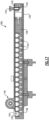
Figure 1 schematically illustrates a welding station. -
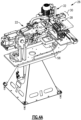
Figure 2 depicts a welding gun and maintenance tool assembly integrated with one another on a pedestal. -
Figure 3 schematically illustrates the maintenance tool assembly, which includes a cap extractor, a cap dresser, and cap dispensers. -
Figures 4A-4D illustrate the maintenance tool assembly in cap extracting, first and second cap dispensing, and cap dressing positions, respectively. -
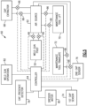
Figure 5 is a schematic depicting a control system for the welding station including welding gun and maintenance tool assembly controls. -
Figures 6-9 illustrate perspective, front, side, and cross-sectional views, respectively, wherein the cross-sectional view is taken along line 9-9 inFigure 8 . -
Figures 10-12 are perspective, exploded, and cross-sectional views, respectively, of the cap extractor, wherein the cross-sectional view is taken along line 12-12 ofFigure 10 . -
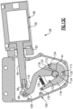
Figures 13A-13C are cross-sectional views along line 13-13 ofFigure 10 and, respectively, of first, second, and a third cap extracting positions. -
Figure 14 is a perspective view of first and second cap dispensers. -
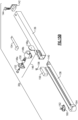
Figures 15A-15B , respectively, are views of a cap dispenser in extended and exploded positions. -
Figure 16 is a cross-sectional view of the cap dispenser in an extended position. -
Figure 17 is a cross-sectional view of the cap dispenser in a closed position. -
Figure 18 is an enlarged cross-sectional view of a cap in an improperly loaded position within the cap dispenser, triggering a fault code. - A
welding station 10 is schematically illustrated inFigure 1 . Oneexample station 10 includes aload fixture 12 that establishes the position ofworkpieces 14 at the entrance to thewelding station 10. Thewelding station 10 includes arobot 18, which may be enclosed by aperimeter fence 16 for safety. -
Workpiece 14 may be placed into theload fixture 12 by an operator or automation. Therobot 18 may retrieveworkpiece 14 from theload fixture 12 using robot end ofarm tooling 20 that holds the workpiece in the desired orientation and configuration. Awelding gun 22 is mounted to abase 24 and spot welds theworkpiece 14, for example. - The welding gun station is commonly employed within robot cells for both spot and projection welding. Such robot cells employ one or more material handling robots to manipulate the workpiece(s) instead of the heavy resistance welding gun. This enables the use of smaller, more agile, and less expensive robots to automate the process. This robot cell configuration is also useful when the process involves multiple resistance welding guns that may be different sizes, configurations, or orientations. Or it may enable the robot to manipulate a workpiece between a number of stations employing different processes necessary to complete an assembly. Processes could for example include metal working, coating application, arc welding, fastener welding, assembly, and inspection.
- The
fence 16 can provide isolation between the robot cell and the electrode maintenance station including amaintenance tool assembly 26 for removing, installing and/or dressing the welding gun electrodes. This barrier would prevent the process on one side from affecting the other. It would therefore permit operations such as manual electrode maintenance or replacing the electrode dispensers to occur without interrupting the robot cycle. - A
maintenance tool assembly 26 is mounted to thebase 24. Periodically, thewelding gun 22 may be pivoted in a rotational path R to bring the welding "electrodes", "tips" or "caps" of thewelding gun 24 to themaintenance tool assembly 26 for replacement and/or dressing. While it is possible in alternative configurations to pivot the welding gun to position the electrodes for extraction or replacement, the disclosed configuration illustrated employs a simple longitudinal translation T to move the tools. This improves the repeatability, control, and sensing of the welding gun pivot operation. It keeps the welding gun stationary during the maintenance operation so there is little chance of accidental collisions or unintended motion while in the electrode maintenance position. - Referring to
Figures 1-3 , themaintenance tool assembly 26 includes acap extractor 28 andcap dispenser 30 including first and second cap dispensers 30A, 30B. Acap dresser 32 is provided at an end of themaintenance tool assembly 26 opposite thecap extractor 28 such that thecap dispenser 30 is arranged therebetween. The described resistance welding gun is for resistance spot welding but aspects of the configuration could be applied to projection welding equipment used to affix components such as fasteners or spacers. - Generally, a typical sequence would be to present the electrode caps to the tip dressing station on a regular basis. The frequency depends on the welding conditions but may be for example every 10, 25 or 100 welds. At that time the tip dresser would use cutters or forming tools to clean or restore the profile of the electrode cap tip so welding consistency can be maintained. After a number of these tip dressing cycles have been performed, it is necessary to replace the electrode cap with a new one. The replacement frequency may relate to the number of tip dressing cycles, a physical attribute such as electrode cap length, a welding performance indicator such as excessive or insufficient welding current, or feedback of weld discontinuities.
- A conventional dressing station is included for periodic light cleaning and shaping of the electrode face(s). When dressing of the electrode is no longer appropriate, an electrode extractor and electrode dispenser can be employed to replace the electrode(s).
- The resistance spot welding gun station is configured to facilitate the required electrode maintenance so there is minimal impact on production throughput. Electrode maintenance is frequently performed during the time the industrial robot is executing material handling (i.e., retrieving workpieces or delivering the completed weldment to the unload station) or another function such as in-line inspection. The described robotic welding cell module permits maintenance to be performed entirely manually, or with automation. The electrode maintenance tools are modular in nature so the system can be reconfigured depending on the business priorities and financial analysis.
- The disclosed resistance welding gun is mounted on a pivot unit assembly that enables the welding electrodes to be presented to a location away from the production area. The pivot is operated by a pneumatic cylinder that rotates the welding gun between hard position stops. The pivot could also be operated by a servo drive or other mechanical or electrical system that facilitates accurate positioning of the welding electrodes. The resistance welding electrodes can be serviced when the robot is being utilized to perform the workpiece manipulation. This reduces the possibility the robot cell throughput will be affected by the electrode maintenance operation.
- The number and position of maintenance tools can be established to suit the anticipated electrode maintenance frequency, production rate, or resistance welding cell configuration. The station could include no maintenance tools to start, where the pivoting mechanism is used alone to present the welding electrodes outside of the robot cell for manual maintenance or replacement. An automatic electrode cap dressing tool could be added for regular lightly cleaning and profiling of the welding face. Additional tooling stations could be added to provide the capability to reshape the welding face or to remove and replace a worn out electrode.
- The maintenance tools are outside of the production space, which can improve access to the electrode maintenance tools for servicing (e.g., emptying chips from the dresser or reloading cap dispenser), put the electrode maintenance tools in a location that is safer or more accessible to the personnel that are necessary to maintain them, permit a configuration that allows servicing of the electrode maintenance tools while the welding equipment is performing a production sequence, and ensure the production cell is not contaminated with errant machining chips, coolant, or electrode caps.
- Referring to
Figure 2 , thewelding gun 22 includes first andsecond arms 52, 54 carrying first andsecond electrode adapters electrode cap 44 is mounted on each of the first andsecond electrode adapters caps 44 may be identical or could have different sizes and shapes to suit the welding conditions. Thebase 24 is supported by apedestal 46 arranged within the work area. Thewelding gun 22 is supported with respect to thebase 24 by apivot 48 that is rotated between first and second positions by apivot cylinder 50. The first and second positions may be 180° from one another. The welding gun is shown in the working position inFigure 2 . The spot welding gun is moved clear of the welding area by a simple and reliable pivoting motion, that also positions the welding electrodes within reach of the integrated electrode maintenance tools. At least part of the time required for the off-line electrode maintenance process can be conducted while the robot continues to perform a material handling function. - Referring to
Figures 2 and3 , thecap extractor 28,cap dispenser 30, andcap dresser 32 are mounted to aplate 38 that is carried by aplatform 34. Theplate 38 is slideably mounted to thebase 24, which may include numerous members secured to one another. This translation stage puts the desired maintenance tool in the required position to service the electrode(s), which may include lifting the tool between a lowered and raised position to service the lower and upper electrode respectively. Themaintenance tool assembly 26 translates along a longitudinal direction T (Fig. 3 ) between numerous positions to place the components of themaintenance tool assembly 26 in the desired position with respect to thecaps 44. Themaintenance tool assembly 26 may also move in a vertical direction L (Fig. 3 ) to lift and lower the maintenance tool assembly with respect to thecaps 44 during maintenance. Because one electrode extractor can be used to remove either electrode cap, the translation stage incorporates the vertical lift so either the upper or lower electrode cap can be aligned with the electrode extractor. Abin 58 collects the used, extracted caps 44. -
Figures 4A-4D illustrate various positions of themaintenance tool assembly 26 with respect to the welding gun. Either or both of the first andsecond arms 52, 54 of thewelding gun 52 may open and close with respect to one another. In one example, one of the arms is fixed and the other arm articulates to open and close about the workpiece during welding operations. In another example, the first and second arms may both open and close about the workpiece. Themaintenance tool assembly 26 lifts or lowers the maintenance tools with respect to thecap 44 and its relative position on the first andsecond arms 52, 54. InFigure 4A , one of thecaps 44 is inserted into thecap extractor 28. Thecap 44 is rotated with respect to its electrode which breaks thecap 44 free from the welding gun. With thecap extractor 28 disengaged from the cap 44 (by raising or lowering the maintenance tool assembly 26), thecap 44 may be released by thecap extractor 28, dropping the cap into thebin 58. - Referring to
Figures 4B and4C , theelectrode adapter cap 44 may be inserted into one of the cap dispensers 30A, 30B of thecap dispenser 30. The first andsecond electrode adapters caps 44 can be removed from the first andsecond electrode adapters cap extractor 28 before installing new caps using the cap dispensers 30A, 30B. Alternatively, the cap may be removed from oneelectrode adapter - The new caps may be dressed by the
cap dresser 32, as shown inFigure 4D . In the example, the caps are dressed simultaneously by closing the first and second electrodes about an aperture of thecap dresser 32. Thecap dresser 32 may also be used to periodically dress used caps before the need to replace thecaps 44. - A
control system 60 is schematically shown inFigure 5 . Thesystem 60 includes anair source 62 that selectively supplies compressed air to various components viacontrol valve 66 that are operated by acontroller 64. Theair source 62 supplies to acap extractor cylinder 68 of thecap extractor 28, a maintenance toolassembly lift cylinder 70, and translatecylinder 72 of themaintenance tool assembly 26 and the weldinggun pivot cylinder 50. Other types of actuators may be used instead of air cylinders, if desired. - The first and
second cap sensors 74, 76 (also shown inFigs. 6-8 ) may be used to detect the presence or absence of acap 44 during the maintenance procedure. One or morecap presence detectors 78 may be used with the first and second cap dispensers 30A, 30B to detect an improper orientation and fault of acap 44 within the cap dispenser 30 (Fig. 18 ). - The
motor 80 of thecap dresser 32 is operated by thecontroller 64. Additionally, thecontroller 64 may also be used to control and monitor thewelding gun 22 during various welding gun operations, as indicated inblock 82, including tracking when the welding gun is in need of tip maintenance. - Referring to
Figures 6-9 , theplatform 34 is slideably supportive with respect to thebase 24 by aslide assembly 86. The translatecylinder 72 moves theplatform 34 with respect to thebase 24 and thewelding gun 22 supported thereon between various discrete longitudinal positions (shown inFigs. 4A-4D ) to align the desired components of themaintenance tool assembly 26 with respect to the electrodes and/or caps. - The
plate 38 is supported with respect to theplatform 34 by guide posts 88. Alift cylinder 70 is arranged laterally between guide posts 88 and vertically between theplatform 34 andplate 38. Thelift cylinder 70 raises and lowers the maintenance tool components to their desired positions. - The first and
second cap sensors cap 44 subsequent to extraction by thecap extractor 28 and installation of a new cap by the first and second cap dispensers 30A, 30B. If a cap is absent when one should be installed or present when it should have been removed, a fault is indicated. - The
cap extractor 28 is illustrated in more detail inFigures 10-12 . Theextractor cylinder 68 includes acylinder body 90 housing a piston. The cylinder body is secured to a mountingplate 92. Arod 94 is connected to the piston within thecylinder body 90 and extends through the mountingplate 92 to aclevis 96. - The
extractor cylinder 68 is mounted to ahousing 100 by spaced apart pivot pins 102, which enables theextractor cylinder 68 to articulate with respect to thehousing 100 during operation. Thehousing 100 may include multiple housing portions 100A-100D, collectively referred to as "thehousing 100." - The
housing 100 includesapertures 106 for receiving the end of anelectrode adapter cap 44. Ends ofcollars 108 are arranged with theapertures 106, and wave springs 114 are arranged concentrically about eachcollar 108. A pair of spaced apartdisks 110 have a recess that receives one side of the wave springs 114. - First and
second arms disks 110. Thefirst arm 116 has ahole 128 that receives apin 98 securing theclevis 96 to thefirst arm 116. Thesecond arm 118 has anend 124 that is received in achannel 122 of the first arm. The first andsecond arms spacer 112 that spaces thedisks 110 with respect to one another and ensures that they rotate together with respect to thehousing 100. Anotherspacer 112 is received within aslot 120 in thesecond arm 118. In the example, threespacers 112 are circumferentially spaced with respect to one another and rotationally affix thedisks 110 to one another. - A biasing
spring 126 interconnects the first andsecond arms complementary teeth 134 toward one another to engage thecap 44. Astop 130 provided on the housing portion 100A limits the travel of thesecond arm 118 during rotation via astop pin 132 carried thereon. - The wave springs 114 enable the
disks 110 to float within thehousing 100 better ensuring alignment with theteeth 134 and thecap 44. That is, there is some flexibility provided by the wave springs 114 to enable thedisk 110 and the associated first andsecond arms cap extractor 28 is not required for effective cap extraction. - The extraction jaw mechanism floats in a plane normal to the center axis of the jaws. This allows the central axis of the extractor jaws to move, if required, to be coincident with the axis of the electrode taper. This prevents a binding force between the taper surfaces that could otherwise be created during rotation when the two axis are not aligned. Increased surface friction due to binding may inhibit axial movement necessary to separate the electrode from the adapter. Such position variation may arise from inaccuracy of the positioner or by bending or deflection of the welding gun or its components. When the electrode is positioned by automation or an industrial robot, the electrode could be misaligned with the cap electrode extractor due to position teaching inaccuracy, positioning repeatability deviation, or deflection within the mechanical system.
- The jaw mechanism floats in the direction of the taper axis. This permits the strain in the electrode and adapter tapers to aid in releasing the taper engagement. The intimate engagement of the tapers is maintained by stress on the material, which causes one or both of the components to deform. A female electrode cap taper for example will expand (stretch) slightly as its taper is engaged over the male taper of the electrode cap adapter. This strain applies a force on the two taper surfaces to lock them together. On a common ¾" (19 mm) diameter female electrode, the distance between initial engagement and locking of the tapers may be 1/16" (1.5 mm). Mounting of the extractor jaw mechanism between the wave springs 114 provides the electrode cap the freedom to move in the direction of the taper axis. By permitting this movement, when the electrode cap is rotated to break the static friction between taper surfaces, the strain on the taper helps to urge the tapers apart. This ensures the electrode is consistently released from the adapter.
- Since the
cap extractor 28 is accessible from either side it is not necessary to change the welding gun orientation for a single tool to extract either the upper or lower electrode. - First, second, and third positions of the cap extractor are respectively illustrated in
Figures 13A-13C . For better visualization, inFigure 13A , the arcs A1 and A2 illustrate the path along which thepin 98 and stoppin 132 move during cap extraction. Thespacer 112 interconnecting first andsecond arms disks 110. The "+" along these paths indicate the elements position in the first, second and third positions. - Referring to
Figure 13A , theextractor cylinder 68 is shown with the piston in a fully retracted position such that the first andsecond arm stop pin 132 engages thestop 130. Once thecap 44 has been positioned between theteeth 134, theextractor cylinder 68 begins to close from the first position shown inFigure 13A to the second position shown inFigure 13B , which more tightly clamps theteeth 134 about thecap 44. In this second position, thestop pin 132 is spaced from thestop 130. - Referring to
Figure 13C , theextractor cylinder 68 is actuated to a fully extended position in which the first andsecond arms cap 44 from itselectrode adapter second arm 118 may engage one of thespacers 112, which was located between the first and second arms. Subsequently, theextractor cylinder 68 is retracted, which returns the first andsecond arms Figure 13A . In this position, once theelectrode adapter cap 44, the cap will simply drop into thebin 58 beneath. - The technique employed for extracting the electrode caps is simply a twisting motion to break the friction of the engaged tapers. When the cylinder advances, the serrated jaws of the extractor bite into the electrode cap to impart the rotation. The configuration of the jaw mechanism enables it to center to the electrode adapter taper, thereby ensuring the applied force is consistent even pressure on the serrations. Prior to the cylinder reaching the limit of rod extension, the cap will have been freed. When the cylinder retracts and the jaws reach the hard stops they will separate and allow the electrode cap to fall into the container provided. If cooling water is released when the cap is removed, it will also be captured by the
bin 58. - The first and second cap dispensers 30A, 30B are illustrated in more detail in
Figure 14 . In the example, the first cap dispenser 30A is in identical construction with respect to the second cap dispenser, only their orientation is different. Thus, the second cap dispenser 30B will be explained in further detail in connection withFigures 15A-17 . - The process of installing a new cap is as simple as closing the welding gun onto the electrode cap. After the friction fit tapers engage, opening the welding gun easily overcomes the sliding friction between electrode caps to remove the electrode cap from the dispenser. As soon as the space occupied by the electrode cap is clear another electrode cap will move towards the outlet.
- The cap dispenser is configured for off-line refilling and quick exchange. The dispenser can be made to a standard length or the length necessary to accommodate the number of electrode caps required between the standard service intervals.
- The dispenser is easily removed from its holder by pulling the spring loaded catch. The dispenser is easily serviced in a similar fashion by pulling the spring loaded catch. There is no cumbersome on-line dispenser loading or replacement process required so dispensers can be loaded off line. This also has the added advantage of easily enabling different electrode caps to be installed in the dispenser when required by a different workpiece or welding condition.
- A
sleeve 136 slideably receives adrawer 138 that houses thecaps 44. Thedrawer 138 includes aramp 140 that selectively cooperates with apin 144 carried by anend cap 142 mounted to the sleeve. Thepin 144 may be spring loaded to bias thepin 144 inward to engage theramp 140 when the drawer is fully inserted and seated with respect to thesleeve 136. Alternatively, thepin 144 may be threadingly moved into and out of an engagement with respect to theramp 140. The dispenser is easy to load since the tray can be fully opened or partially opened for filling, depending on which method is easiest for a particular size and geometry of welding electrode. - Electrode caps are urged towards the outlet of the dispenser by a follower, which is pulled by a constant force spring. A
spring assembly 146 is mounted to thesleeve 136 to urge aslide block 156 located within thedrawer 138 in a direction that forces thecaps 44 to a position beneath anaperture 162 in aplate 160. In an example, thespring assembly 146 includes a spring housing 148 having first and second housing portions 148A, 148B. The spring housing 148 receives adrum 150 rotatable about aroller pin 152 that secures the housing portions 148A, 148B to one another. Aclock spring 154 is affixed to thedrum 150 at one end and to theslide block 156 at an opposite end by afastener 158. Theclock spring 154 wraps about thedrum 150 in a normally biased position. Thus, theslide block 156 is pulled leftward as illustrated inFigure 17 to push the stack ofcaps 44 toward theaperture 162. - The presence of the cap at the outlet is verified by a sensor, which confirms the straight side of the electrode cap skirt is tight against the stop. A through beam light sensor is provided to ensure there is a properly oriented electrode cap at the discharge point. A fiber optic through-beam light sensor is referenced, but other sensors can be employed. The sensor has the secondary function of verifying there is an electrode cap in the dispenser since the follower is configured so it will not operate or activate the electrode cap detection sensor.
- Referring to
Figure 18 , thedrawer 138 includes ahole 164 that may cooperate with thecap presence detector 78, which may be a laser. If acap 44 is oriented improperly such that thehole 164 is obstructed, a fault condition may be indicated requiring the cap dispenser to be serviced. - The disclosed arrangement uses a simple mechanical system to pivot the welding gun to move the electrodes out of the work area of the welding cell. Stand-alone electrode maintenance tools and simple translation stages achieve a total solution that is easy to expand, more economical, and easier to maintain. Because the maintenance tools do not have a footprint within the robot envelope, they do not affect or require any of the reach of the robot. The maintenance tools are not exposed to the hazards and contamination found within the welding cell. The robot cell is not exposed to the hazards and contamination that may occur at the maintenance tools. The maintenance tools may be made accessible for service while the robot is cycling.
- The maintenance tools are moved to defined positions so there is no requirement for position variation compensation schemes, such as spring centered slides, which can contribute to erratic machining results in the prior art due to chattering.
- Movement in the plane perpendicular to the taper axis minimizes the possibility a side force could be applied to the taper surfaces, which could inhibit the taper separation. Movement in the direction of the taper axis ensures the tapers can separate without the need for external force or movement.
- The design includes a simple round orifice that is less sensitive to electrode geometry variation such as the diameter or surface condition of the electrode cap. It also does not rely on the accessible surface of the taper or of electrode. The design is much simpler than others which employ shafts, gears, cams, and motors. This reduces the cost and improves the operational reliability.
- The linear dispensers can be made to accommodate a variety of electrode cap sizes. Spring loaded pins are employed to latch the linear dispenser into its holder and to retain the drawer in the closed position. Therefore, the functions of filling and replacing the dispenser may be easy accomplished independently.
- Filling may be performed off line if desired. During filling, the dispenser can be held at an orientation that best exploits gravity to aid the process. The length of the exposed opening during loading can also be coordinated to minimize the opportunity for electrodes to tip over, if their geometry predisposes them to do so. The action of closing of the dispenser, applies spring pressure that will be used to urge the cap electrodes towards the opening.
- Replacement of the dispenser can be performed to minimize interaction time or for convenience. It can also be done to change the electrode geometry if a changeover is performed to enable the robot cell to produce different weldments.
- It should also be understood that although a particular component arrangement is disclosed in the illustrated embodiment, other arrangements will benefit herefrom. Although particular step sequences are shown, and described, it should be understood that steps may be performed in any order, separated or combined unless otherwise indicated in the appended claims, and will still benefit from the present invention.
- Although the different examples have specific components shown in the illustrations, embodiments of this invention are not limited to those particular combinations.
- Although an example embodiment has been disclosed, a worker of ordinary skill in this art would recognize that certain modifications would come within the scope of the appended claims. For that reason, the following claims should be studied to determine their true scope and content.
Claims (6)
- A cap extractor (28) for a welding gun (22) comprising:a housing (100);spaced apart disks (110) arranged in the housing (100), the spaced apart disks (110) being affixed to one another by means of a spacer pin (112), the spaced apart discs (110) further being floatingly supported inside the housing (100) by means of a pair of springs (114);first and second arms (116, 118) arranged between and mounted to the disks (110), the first and second arms (116, 118) pivotably secured with respect to one another by means of the spacer pin (112), each of the first and second arms (116, 118) having teeth (134) configured to engage a welding cap (44);the first arm (116), second arm (118) and the disks (110) being configured to float by deflecting the springs (114) and thereby moving relative to the housing (100) in first and second directions transverse to one another to ensure alignment between the teeth (134) and the welding cap (44); andan actuator pivotally attached to the housing (100), the actuator operatively connected to the first arm (116) to rotate the first and second arms along with the disks (110), the actuator configured to articulate relative to the housing (100) during rotation of the first arm (116) in the housing (100).
- The cap extractor (28) of claim 1, wherein the springs (114) are wave springs, each wave spring received in a recess of one of the disks (110), and a collar (108) is arranged between each disk (110) and the housing (100) to locate a respective wave spring relative to the housing (100).
- The cap extractor (28) of claim 1, wherein a biasing spring (126) is interconnected to the first and second arms (116, 118) to urge the first and second arms (116, 118) toward one another.
- A method of removing a cap (44) from a welding gun (22) using the cap extractor (28) of claim 1 comprising the steps of:receiving a welding cap (44) having a centerline between teeth (134) of the first and second arms (116, 118);floating the arms (116, 118) along the centerline and laterally relative to the centerline during the receiving step to permit alignment between the teeth (134) and the welding cap (44); andtwisting the welding cap (44) from a welding gun (22) by articulating the actuator relative to the housing (100) and rotating the first and second arms (116, 118) relative to the welding gun (22).
- The method of claim 4, comprising the step of normally biasing the first and second arms (116, 118) toward one another, and the receiving step separates the first and second arms (116, 118).
- The method of claim 5, wherein one of the first and second arms (116, 118) abuts a stop (130) preceding the receiving step, and the one of the first and second arms (116, 118) is spaced from the stop (130) during the twisting step.
Priority Applications (1)
| Application Number | Priority Date | Filing Date | Title |
|---|---|---|---|
| EP20215211.2A EP3848143B1 (en) | 2018-06-12 | 2018-06-12 | Integrated electrode maintenance for robotic welding cell including cap extractor |
Applications Claiming Priority (3)
| Application Number | Priority Date | Filing Date | Title |
|---|---|---|---|
| PCT/CA2018/050702 WO2019237174A1 (en) | 2018-06-12 | 2018-06-12 | Integrated electrode maintenance for robotic welding cell |
| EP20215211.2A EP3848143B1 (en) | 2018-06-12 | 2018-06-12 | Integrated electrode maintenance for robotic welding cell including cap extractor |
| EP18922953.7A EP3807040B1 (en) | 2018-06-12 | 2018-06-12 | Robotic welding cell with integrated electrode maintenance |
Related Parent Applications (2)
| Application Number | Title | Priority Date | Filing Date |
|---|---|---|---|
| EP18922953.7A Division EP3807040B1 (en) | 2018-06-12 | 2018-06-12 | Robotic welding cell with integrated electrode maintenance |
| EP18922953.7A Division-Into EP3807040B1 (en) | 2018-06-12 | 2018-06-12 | Robotic welding cell with integrated electrode maintenance |
Publications (3)
| Publication Number | Publication Date |
|---|---|
| EP3848143A1 EP3848143A1 (en) | 2021-07-14 |
| EP3848143C0 EP3848143C0 (en) | 2025-03-12 |
| EP3848143B1 true EP3848143B1 (en) | 2025-03-12 |
Family
ID=68842426
Family Applications (2)
| Application Number | Title | Priority Date | Filing Date |
|---|---|---|---|
| EP18922953.7A Active EP3807040B1 (en) | 2018-06-12 | 2018-06-12 | Robotic welding cell with integrated electrode maintenance |
| EP20215211.2A Active EP3848143B1 (en) | 2018-06-12 | 2018-06-12 | Integrated electrode maintenance for robotic welding cell including cap extractor |
Family Applications Before (1)
| Application Number | Title | Priority Date | Filing Date |
|---|---|---|---|
| EP18922953.7A Active EP3807040B1 (en) | 2018-06-12 | 2018-06-12 | Robotic welding cell with integrated electrode maintenance |
Country Status (7)
| Country | Link |
|---|---|
| US (4) | US20210252630A1 (en) |
| EP (2) | EP3807040B1 (en) |
| CN (2) | CN112399900A (en) |
| BR (1) | BR112020025320B1 (en) |
| CA (2) | CA3297287A1 (en) |
| MX (1) | MX2020013328A (en) |
| WO (1) | WO2019237174A1 (en) |
Families Citing this family (2)
| Publication number | Priority date | Publication date | Assignee | Title |
|---|---|---|---|---|
| CN114131260B (en) * | 2021-12-17 | 2023-05-26 | 长春市众诚智能科技有限公司 | Intelligent welding equipment for automobile fender |
| KR102957409B1 (en) * | 2022-11-08 | 2026-04-28 | 한국티앤엠(주) | Weld tip remover |
Family Cites Families (49)
| Publication number | Priority date | Publication date | Assignee | Title |
|---|---|---|---|---|
| US4794221A (en) | 1986-11-26 | 1988-12-27 | Toyota Jidosha Kabushiki Kaisha | Apparatus and method for exchanging electrode chips used for resistance welding |
| JPH0686021B2 (en) | 1988-02-04 | 1994-11-02 | 本田技研工業株式会社 | Welding gun electrode tip changer |
| SU1729717A1 (en) * | 1990-04-16 | 1992-04-30 | Приморское центральное конструкторское бюро | Arrangement for removing electrodes of resistance spot welding machines |
| US5073692A (en) * | 1990-11-13 | 1991-12-17 | Jackson Donald T | Automatic welding electrode cap changer |
| US5495663A (en) | 1993-06-04 | 1996-03-05 | Saito; Akihiro | Apparatus for removing an electrode chip from a shank of a resistance welding machine |
| JPH079166A (en) | 1993-06-25 | 1995-01-13 | Honda Motor Co Ltd | Welding tip dressing equipment |
| CA2121988A1 (en) * | 1994-04-22 | 1995-10-23 | Laurent Voilmy | Apparatus for automatically replacing welding electrodes |
| JP3024473U (en) | 1995-11-09 | 1996-05-21 | 利晃 島田 | Electrode tip removal mechanism for spot welding |
| JP3587684B2 (en) | 1997-06-27 | 2004-11-10 | 利晃 島田 | Electrode tip loosening device for spot welding |
| DE19817803C1 (en) * | 1998-03-06 | 1999-10-21 | Wedo Werkzeugbau Gmbh | Method and apparatus for removing electrode caps, in particular, from a conical seating carried by a welding robot |
| US6188038B1 (en) | 1998-07-01 | 2001-02-13 | Kyokutoh Company | Device for removing an electrode tip |
| JP3650928B2 (en) | 2000-05-26 | 2005-05-25 | 株式会社キョクトー | Dresser device |
| JP4181731B2 (en) * | 2000-06-08 | 2008-11-19 | セキ工業株式会社 | Electrode tip removal device for resistance welding |
| DE10124243C1 (en) * | 2001-05-18 | 2002-11-21 | Reu Schweistechnik Gmbh | Interchangeable device, for spot welding electrodes, comprises sector-like clamping jaws arranged around a central electrode insertion region in a fixed holder |
| US6667454B2 (en) | 2002-04-29 | 2003-12-23 | Robtex Inc. | Apparatus and method for separating and replacing a cap from a shank of a tip of a welding electrode |
| ES2217976B1 (en) | 2003-04-25 | 2006-06-01 | Jose Fuentes Raga | "DEVICE FOR REMOVING THE ELECTRODES OF A WELDING UNIT COMMANDED BY A ROBOT". |
| JP4518758B2 (en) | 2003-07-23 | 2010-08-04 | Obara株式会社 | Stationary electrode tip removal device |
| WO2005123321A1 (en) | 2004-06-15 | 2005-12-29 | Shinkokiki Co., Ltd. | Cap tip removing device of welding machine |
| US7264402B2 (en) * | 2005-03-10 | 2007-09-04 | Corning Cable Systems Llc | Multi-fiber optic receptacle and plug assembly |
| CN101142063B (en) * | 2005-07-19 | 2010-05-19 | 欧姆龙株式会社 | Worker Safety Management System |
| DE102005035915B3 (en) | 2005-07-28 | 2006-08-17 | Kaeseler, Werner, Dipl.-Ing. | Spot welding machine cap change assembly has two opposing jaws both with approximately parallel grip surfaces |
| US8809725B2 (en) * | 2008-01-04 | 2014-08-19 | GM Global Technology Operations LLC | Welding electrode assembly having self-aligning features |
| ES2455221T3 (en) | 2009-02-25 | 2014-04-15 | Aeg Svs Schweisstechnik Gmbh | Spinning device of an electrode tip cutter for spot welding |
| JP5251649B2 (en) | 2009-03-19 | 2013-07-31 | スズキ株式会社 | Spot welding tip removal device |
| DE202012000498U1 (en) * | 2012-01-19 | 2012-03-01 | Reinhard Bäker | Device for automatically releasing and removing the spot welding cap from the welding electrode of a spot welding gun - Cap puller - |
| US9387549B2 (en) * | 2012-05-18 | 2016-07-12 | Lincoln Global, Inc. | Adjustable clamping mechanism of a weld head with quick release insert |
| KR101216192B1 (en) | 2012-07-31 | 2012-12-28 | 이승해 | Apparatus for changing welding tip of a spot welding gun |
| BR112013020111B1 (en) * | 2013-03-26 | 2018-07-24 | Kyokutoh Co Ltd | spot welding electrode removal apparatus |
| US9207667B2 (en) * | 2013-04-16 | 2015-12-08 | Siemens Industry Software Ltd. | Automatic generation of robotic processes for symmetric products |
| DE102013214549A1 (en) * | 2013-07-25 | 2015-01-29 | Bayerische Motoren Werke Aktiengesellschaft | Welding cap magazine |
| DE102013216623A1 (en) * | 2013-08-22 | 2015-02-26 | Robert Bosch Gmbh | DEVICE FOR CHANGING ELECTRODE CAPS OF A WELDING MACHINE AND WELDING METHOD |
| EP2859988A1 (en) * | 2013-10-14 | 2015-04-15 | Kyokutoh Europe GmbH | Spot welding device |
| MX371015B (en) | 2014-02-06 | 2020-01-13 | Kyokutoh Co Ltd | Rotating work device. |
| WO2015135405A1 (en) * | 2014-03-14 | 2015-09-17 | 广州明珞汽车装备有限公司 | Integrated machine for resharpening and replacing electrode cap |
| WO2015178643A1 (en) | 2014-05-19 | 2015-11-26 | 최광술 | Apparatus for replacing welding tip of welder and apparatus for supplying same |
| CN204195663U (en) | 2014-10-28 | 2015-03-11 | 广州市极动焊接机械有限公司 | A kind of multifunction electric polar cap removes and installs device |
| US9745857B2 (en) | 2014-12-01 | 2017-08-29 | Pratt & Whitney Canada Corp. | Sealing assembly |
| CN104801973B (en) * | 2015-04-29 | 2017-06-20 | 广州市极动焊接机械有限公司 | A kind of electrode cap dismounts reconditioning equipment integrating automatically |
| CN104985425B (en) * | 2015-06-05 | 2017-07-11 | 深圳市鸿栢科技实业有限公司 | A kind of more exchange device that repairs a die of electrode welder cap |
| US11347191B2 (en) * | 2015-07-29 | 2022-05-31 | Illinois Tool Works Inc. | System and method to facilitate welding software as a service |
| WO2017130235A1 (en) * | 2016-01-27 | 2017-08-03 | 株式会社キョクトー | Electrode tip removal device and hammer |
| WO2017168468A1 (en) * | 2016-03-31 | 2017-10-05 | 株式会社キョクトー | Electrode chip removal device |
| ES2750790T3 (en) * | 2016-04-11 | 2020-03-27 | Tipman Co Ltd | Rotary replacement device |
| KR101761143B1 (en) * | 2016-10-07 | 2017-07-25 | 한국 오바라 주식회사 | Tip changer for spot welding machine |
| US10906124B2 (en) * | 2017-02-09 | 2021-02-02 | G.E. Schmidt, Inc. | Swing arm assembly with lift assembly |
| CN206912962U (en) * | 2017-04-19 | 2018-01-23 | 广州明珞汽车装备有限公司 | A kind of electrode cap automated maintenance equipment |
| JP6236192B1 (en) * | 2017-05-15 | 2017-11-22 | 株式会社キョクトー | Electrode storage device for spot welding |
| CN107520532B (en) * | 2017-08-23 | 2020-02-07 | 武汉艾森威尔科技有限公司 | Servo-driven automatic die repairing and electrode cap replacing integrated mechanism |
| KR102002803B1 (en) * | 2018-12-27 | 2019-07-23 | 주식회사 썬에이치에스티 | System and method of safety accident control using UWB based real time location |
-
2018
- 2018-06-12 US US16/973,681 patent/US20210252630A1/en not_active Abandoned
- 2018-06-12 BR BR112020025320-0A patent/BR112020025320B1/en active IP Right Grant
- 2018-06-12 WO PCT/CA2018/050702 patent/WO2019237174A1/en not_active Ceased
- 2018-06-12 EP EP18922953.7A patent/EP3807040B1/en active Active
- 2018-06-12 CN CN201880095633.1A patent/CN112399900A/en active Pending
- 2018-06-12 MX MX2020013328A patent/MX2020013328A/en unknown
- 2018-06-12 EP EP20215211.2A patent/EP3848143B1/en active Active
- 2018-06-12 CA CA3297287A patent/CA3297287A1/en active Pending
- 2018-06-12 CN CN202110229564.2A patent/CN112975096B/en active Active
- 2018-06-12 CA CA3103303A patent/CA3103303A1/en active Pending
-
2020
- 2020-12-09 US US17/116,695 patent/US11945041B2/en active Active
- 2020-12-09 US US17/116,734 patent/US11858058B2/en active Active
-
2024
- 2024-04-03 US US18/625,573 patent/US12285816B2/en active Active
Also Published As
| Publication number | Publication date |
|---|---|
| MX2020013328A (en) | 2021-03-02 |
| CA3103303A1 (en) | 2019-12-19 |
| EP3848143A1 (en) | 2021-07-14 |
| EP3807040C0 (en) | 2026-04-08 |
| BR122020026900A2 (en) | 2021-03-23 |
| US12285816B2 (en) | 2025-04-29 |
| US11858058B2 (en) | 2024-01-02 |
| EP3807040A1 (en) | 2021-04-21 |
| CN112399900A (en) | 2021-02-23 |
| US11945041B2 (en) | 2024-04-02 |
| US20240246168A1 (en) | 2024-07-25 |
| BR112020025320B1 (en) | 2023-05-16 |
| CA3297287A1 (en) | 2026-03-02 |
| CN112975096B (en) | 2023-03-03 |
| CN112975096A (en) | 2021-06-18 |
| EP3807040A4 (en) | 2022-03-30 |
| WO2019237174A1 (en) | 2019-12-19 |
| EP3848143C0 (en) | 2025-03-12 |
| US20210252630A1 (en) | 2021-08-19 |
| BR112020025320A2 (en) | 2021-03-09 |
| EP3807040B1 (en) | 2026-04-08 |
| US20210086288A1 (en) | 2021-03-25 |
| US20210086289A1 (en) | 2021-03-25 |
Similar Documents
| Publication | Publication Date | Title |
|---|---|---|
| US12285816B2 (en) | Integrated electrode maintenance for robotic welding cell | |
| US6512195B2 (en) | Modular welding machine | |
| JP2682916B2 (en) | Welding torch, nozzle replacing device for the welding torch, tip cleaning device, wire cutting device, automatic welding device, and control method for automatic welding device | |
| KR101433814B1 (en) | Magazine for electrode caps | |
| US4794221A (en) | Apparatus and method for exchanging electrode chips used for resistance welding | |
| CN111182995B (en) | Jacket assembly for fastener feeding apparatus | |
| US5073692A (en) | Automatic welding electrode cap changer | |
| JPH0253199B2 (en) | ||
| EP3037190B1 (en) | Gripping device for mechanical fasteners | |
| US20200290144A1 (en) | System, method and apparatus for welding tubes | |
| CA2121988A1 (en) | Apparatus for automatically replacing welding electrodes | |
| KR20150002590A (en) | Device for filling cartridges for electrode caps | |
| US20110188952A1 (en) | Stabilizer for dressing electrodes and method of using the same | |
| US20060243706A1 (en) | Method for controlling and/or adjusting the movement of an electrode holder | |
| EP0395421B1 (en) | Feed device of welding bolt | |
| US6106221A (en) | Robot-based dispensing station | |
| JPH0354241B2 (en) | ||
| BR122020026900B1 (en) | COVER EXTRACTOR FOR A WELDING GUN AND METHOD FOR REMOVING A COVER FROM A WELDING GUN | |
| CN216858670U (en) | Automatic welding equipment for handle body and handle seat | |
| KR102148397B1 (en) | upper module for gas supply apparatus of gas cylinder | |
| KR102550252B1 (en) | Sectional bending automation device for parts | |
| US6314635B1 (en) | Integrated crimp bias apparatus and method | |
| CN116511427A (en) | Automatic temperature measurement, sampling and hydrogen determination device for tundish | |
| GB2146565A (en) | Automatic welding system | |
| HK1209385B (en) | Device for filling magazines with electrode caps |
Legal Events
| Date | Code | Title | Description |
|---|---|---|---|
| PUAI | Public reference made under article 153(3) epc to a published international application that has entered the european phase |
Free format text: ORIGINAL CODE: 0009012 |
|
| STAA | Information on the status of an ep patent application or granted ep patent |
Free format text: STATUS: THE APPLICATION HAS BEEN PUBLISHED |
|
| AC | Divisional application: reference to earlier application |
Ref document number: 3807040 Country of ref document: EP Kind code of ref document: P |
|
| AK | Designated contracting states |
Kind code of ref document: A1 Designated state(s): AL AT BE BG CH CY CZ DE DK EE ES FI FR GB GR HR HU IE IS IT LI LT LU LV MC MK MT NL NO PL PT RO RS SE SI SK SM TR |
|
| STAA | Information on the status of an ep patent application or granted ep patent |
Free format text: STATUS: REQUEST FOR EXAMINATION WAS MADE |
|
| 17P | Request for examination filed |
Effective date: 20211220 |
|
| RBV | Designated contracting states (corrected) |
Designated state(s): AL AT BE BG CH CY CZ DE DK EE ES FI FR GB GR HR HU IE IS IT LI LT LU LV MC MK MT NL NO PL PT RO RS SE SI SK SM TR |
|
| STAA | Information on the status of an ep patent application or granted ep patent |
Free format text: STATUS: EXAMINATION IS IN PROGRESS |
|
| 17Q | First examination report despatched |
Effective date: 20230712 |
|
| GRAP | Despatch of communication of intention to grant a patent |
Free format text: ORIGINAL CODE: EPIDOSNIGR1 |
|
| STAA | Information on the status of an ep patent application or granted ep patent |
Free format text: STATUS: GRANT OF PATENT IS INTENDED |
|
| INTG | Intention to grant announced |
Effective date: 20241008 |
|
| GRAS | Grant fee paid |
Free format text: ORIGINAL CODE: EPIDOSNIGR3 |
|
| GRAA | (expected) grant |
Free format text: ORIGINAL CODE: 0009210 |
|
| STAA | Information on the status of an ep patent application or granted ep patent |
Free format text: STATUS: THE PATENT HAS BEEN GRANTED |
|
| AC | Divisional application: reference to earlier application |
Ref document number: 3807040 Country of ref document: EP Kind code of ref document: P |
|
| AK | Designated contracting states |
Kind code of ref document: B1 Designated state(s): AL AT BE BG CH CY CZ DE DK EE ES FI FR GB GR HR HU IE IS IT LI LT LU LV MC MK MT NL NO PL PT RO RS SE SI SK SM TR |
|
| REG | Reference to a national code |
Ref country code: GB Ref legal event code: FG4D |
|
| REG | Reference to a national code |
Ref country code: CH Ref legal event code: EP |
|
| REG | Reference to a national code |
Ref country code: DE Ref legal event code: R096 Ref document number: 602018080183 Country of ref document: DE |
|
| REG | Reference to a national code |
Ref country code: IE Ref legal event code: FG4D |
|
| U01 | Request for unitary effect filed |
Effective date: 20250411 |
|
| U07 | Unitary effect registered |
Designated state(s): AT BE BG DE DK EE FI FR IT LT LU LV MT NL PT RO SE SI Effective date: 20250422 |
|
| PG25 | Lapsed in a contracting state [announced via postgrant information from national office to epo] |
Ref country code: RS Free format text: LAPSE BECAUSE OF FAILURE TO SUBMIT A TRANSLATION OF THE DESCRIPTION OR TO PAY THE FEE WITHIN THE PRESCRIBED TIME-LIMIT Effective date: 20250612 |
|
| PG25 | Lapsed in a contracting state [announced via postgrant information from national office to epo] |
Ref country code: ES Free format text: LAPSE BECAUSE OF FAILURE TO SUBMIT A TRANSLATION OF THE DESCRIPTION OR TO PAY THE FEE WITHIN THE PRESCRIBED TIME-LIMIT Effective date: 20250312 |
|
| PG25 | Lapsed in a contracting state [announced via postgrant information from national office to epo] |
Ref country code: NO Free format text: LAPSE BECAUSE OF FAILURE TO SUBMIT A TRANSLATION OF THE DESCRIPTION OR TO PAY THE FEE WITHIN THE PRESCRIBED TIME-LIMIT Effective date: 20250612 |
|
| PG25 | Lapsed in a contracting state [announced via postgrant information from national office to epo] |
Ref country code: HR Free format text: LAPSE BECAUSE OF FAILURE TO SUBMIT A TRANSLATION OF THE DESCRIPTION OR TO PAY THE FEE WITHIN THE PRESCRIBED TIME-LIMIT Effective date: 20250312 |
|
| U20 | Renewal fee for the european patent with unitary effect paid |
Year of fee payment: 8 Effective date: 20250610 |
|
| PG25 | Lapsed in a contracting state [announced via postgrant information from national office to epo] |
Ref country code: GR Free format text: LAPSE BECAUSE OF FAILURE TO SUBMIT A TRANSLATION OF THE DESCRIPTION OR TO PAY THE FEE WITHIN THE PRESCRIBED TIME-LIMIT Effective date: 20250613 |
|
| PG25 | Lapsed in a contracting state [announced via postgrant information from national office to epo] |
Ref country code: SM Free format text: LAPSE BECAUSE OF FAILURE TO SUBMIT A TRANSLATION OF THE DESCRIPTION OR TO PAY THE FEE WITHIN THE PRESCRIBED TIME-LIMIT Effective date: 20250312 |
|
| PG25 | Lapsed in a contracting state [announced via postgrant information from national office to epo] |
Ref country code: PL Free format text: LAPSE BECAUSE OF FAILURE TO SUBMIT A TRANSLATION OF THE DESCRIPTION OR TO PAY THE FEE WITHIN THE PRESCRIBED TIME-LIMIT Effective date: 20250312 |
|
| PG25 | Lapsed in a contracting state [announced via postgrant information from national office to epo] |
Ref country code: CZ Free format text: LAPSE BECAUSE OF FAILURE TO SUBMIT A TRANSLATION OF THE DESCRIPTION OR TO PAY THE FEE WITHIN THE PRESCRIBED TIME-LIMIT Effective date: 20250312 |
|
| PG25 | Lapsed in a contracting state [announced via postgrant information from national office to epo] |
Ref country code: SK Free format text: LAPSE BECAUSE OF FAILURE TO SUBMIT A TRANSLATION OF THE DESCRIPTION OR TO PAY THE FEE WITHIN THE PRESCRIBED TIME-LIMIT Effective date: 20250312 |
|
| PG25 | Lapsed in a contracting state [announced via postgrant information from national office to epo] |
Ref country code: IS Free format text: LAPSE BECAUSE OF FAILURE TO SUBMIT A TRANSLATION OF THE DESCRIPTION OR TO PAY THE FEE WITHIN THE PRESCRIBED TIME-LIMIT Effective date: 20250712 |
|
| PLBE | No opposition filed within time limit |
Free format text: ORIGINAL CODE: 0009261 |
|
| STAA | Information on the status of an ep patent application or granted ep patent |
Free format text: STATUS: NO OPPOSITION FILED WITHIN TIME LIMIT |
|
| REG | Reference to a national code |
Ref country code: CH Ref legal event code: L10 Free format text: ST27 STATUS EVENT CODE: U-0-0-L10-L00 (AS PROVIDED BY THE NATIONAL OFFICE) Effective date: 20260121 |
|
| REG | Reference to a national code |
Ref country code: CH Ref legal event code: H13 Free format text: ST27 STATUS EVENT CODE: U-0-0-H10-H13 (AS PROVIDED BY THE NATIONAL OFFICE) Effective date: 20260127 |
|
| PG25 | Lapsed in a contracting state [announced via postgrant information from national office to epo] |
Ref country code: MC Free format text: LAPSE BECAUSE OF FAILURE TO SUBMIT A TRANSLATION OF THE DESCRIPTION OR TO PAY THE FEE WITHIN THE PRESCRIBED TIME-LIMIT Effective date: 20250312 |
|
| 26N | No opposition filed |
Effective date: 20251215 |
|
| GBPC | Gb: european patent ceased through non-payment of renewal fee |
Effective date: 20250612 |
|
| PG25 | Lapsed in a contracting state [announced via postgrant information from national office to epo] |
Ref country code: GB Free format text: LAPSE BECAUSE OF NON-PAYMENT OF DUE FEES Effective date: 20250612 |
|
| PG25 | Lapsed in a contracting state [announced via postgrant information from national office to epo] |
Ref country code: IE Free format text: LAPSE BECAUSE OF NON-PAYMENT OF DUE FEES Effective date: 20250612 |
|
| PG25 | Lapsed in a contracting state [announced via postgrant information from national office to epo] |
Ref country code: CH Free format text: LAPSE BECAUSE OF NON-PAYMENT OF DUE FEES Effective date: 20250630 |
|
| U1N | Appointed representative for the unitary patent procedure changed after the registration of the unitary effect |
Representative=s name: MARKS & CLERK LLP; GB |