EP3848081A1 - Neurovascular insertion tool - Google Patents
Neurovascular insertion tool Download PDFInfo
- Publication number
- EP3848081A1 EP3848081A1 EP20215379.7A EP20215379A EP3848081A1 EP 3848081 A1 EP3848081 A1 EP 3848081A1 EP 20215379 A EP20215379 A EP 20215379A EP 3848081 A1 EP3848081 A1 EP 3848081A1
- Authority
- EP
- European Patent Office
- Prior art keywords
- insertion apparatus
- microcatheter
- rhv
- longitudinal body
- neurovascular
- Prior art date
- Legal status (The legal status is an assumption and is not a legal conclusion. Google has not performed a legal analysis and makes no representation as to the accuracy of the status listed.)
- Granted
Links
Images




Classifications
-
- A—HUMAN NECESSITIES
- A61—MEDICAL OR VETERINARY SCIENCE; HYGIENE
- A61B—DIAGNOSIS; SURGERY; IDENTIFICATION
- A61B17/00—Surgical instruments, devices or methods
- A61B17/22—Implements for squeezing-off ulcers or the like on inner organs of the body; Implements for scraping-out cavities of body organs, e.g. bones; for invasive removal or destruction of calculus using mechanical vibrations; for removing obstructions in blood vessels, not otherwise provided for
-
- A—HUMAN NECESSITIES
- A61—MEDICAL OR VETERINARY SCIENCE; HYGIENE
- A61M—DEVICES FOR INTRODUCING MEDIA INTO, OR ONTO, THE BODY; DEVICES FOR TRANSDUCING BODY MEDIA OR FOR TAKING MEDIA FROM THE BODY; DEVICES FOR PRODUCING OR ENDING SLEEP OR STUPOR
- A61M25/00—Catheters; Hollow probes
-
- A—HUMAN NECESSITIES
- A61—MEDICAL OR VETERINARY SCIENCE; HYGIENE
- A61M—DEVICES FOR INTRODUCING MEDIA INTO, OR ONTO, THE BODY; DEVICES FOR TRANSDUCING BODY MEDIA OR FOR TAKING MEDIA FROM THE BODY; DEVICES FOR PRODUCING OR ENDING SLEEP OR STUPOR
- A61M39/00—Tubes, tube connectors, tube couplings, valves, access sites or the like, specially adapted for medical use
- A61M39/02—Access sites
- A61M39/0247—Semi-permanent or permanent transcutaneous or percutaneous access sites to the inside of the body
-
- A—HUMAN NECESSITIES
- A61—MEDICAL OR VETERINARY SCIENCE; HYGIENE
- A61B—DIAGNOSIS; SURGERY; IDENTIFICATION
- A61B17/00—Surgical instruments, devices or methods
- A61B17/32—Surgical cutting instruments
- A61B17/3205—Excision instruments
- A61B17/3207—Atherectomy devices working by cutting or abrading; Similar devices specially adapted for non-vascular obstructions
-
- A—HUMAN NECESSITIES
- A61—MEDICAL OR VETERINARY SCIENCE; HYGIENE
- A61M—DEVICES FOR INTRODUCING MEDIA INTO, OR ONTO, THE BODY; DEVICES FOR TRANSDUCING BODY MEDIA OR FOR TAKING MEDIA FROM THE BODY; DEVICES FOR PRODUCING OR ENDING SLEEP OR STUPOR
- A61M25/00—Catheters; Hollow probes
- A61M25/0043—Catheters; Hollow probes characterised by structural features
-
- A—HUMAN NECESSITIES
- A61—MEDICAL OR VETERINARY SCIENCE; HYGIENE
- A61M—DEVICES FOR INTRODUCING MEDIA INTO, OR ONTO, THE BODY; DEVICES FOR TRANSDUCING BODY MEDIA OR FOR TAKING MEDIA FROM THE BODY; DEVICES FOR PRODUCING OR ENDING SLEEP OR STUPOR
- A61M25/00—Catheters; Hollow probes
- A61M25/10—Balloon catheters
-
- A—HUMAN NECESSITIES
- A61—MEDICAL OR VETERINARY SCIENCE; HYGIENE
- A61M—DEVICES FOR INTRODUCING MEDIA INTO, OR ONTO, THE BODY; DEVICES FOR TRANSDUCING BODY MEDIA OR FOR TAKING MEDIA FROM THE BODY; DEVICES FOR PRODUCING OR ENDING SLEEP OR STUPOR
- A61M39/00—Tubes, tube connectors, tube couplings, valves, access sites or the like, specially adapted for medical use
- A61M39/02—Access sites
- A61M39/06—Haemostasis valves, i.e. gaskets sealing around a needle, catheter or the like, closing on removal thereof
-
- A—HUMAN NECESSITIES
- A61—MEDICAL OR VETERINARY SCIENCE; HYGIENE
- A61M—DEVICES FOR INTRODUCING MEDIA INTO, OR ONTO, THE BODY; DEVICES FOR TRANSDUCING BODY MEDIA OR FOR TAKING MEDIA FROM THE BODY; DEVICES FOR PRODUCING OR ENDING SLEEP OR STUPOR
- A61M39/00—Tubes, tube connectors, tube couplings, valves, access sites or the like, specially adapted for medical use
- A61M39/08—Tubes; Storage means specially adapted therefor
-
- A—HUMAN NECESSITIES
- A61—MEDICAL OR VETERINARY SCIENCE; HYGIENE
- A61B—DIAGNOSIS; SURGERY; IDENTIFICATION
- A61B17/00—Surgical instruments, devices or methods
- A61B17/34—Trocars; Puncturing needles
- A61B17/3417—Details of tips or shafts, e.g. grooves, expandable, bendable; Multiple coaxial sliding cannulas, e.g. for dilating
- A61B17/3421—Cannulas
- A61B17/3423—Access ports, e.g. toroid shape introducers for instruments or hands
-
- A—HUMAN NECESSITIES
- A61—MEDICAL OR VETERINARY SCIENCE; HYGIENE
- A61B—DIAGNOSIS; SURGERY; IDENTIFICATION
- A61B17/00—Surgical instruments, devices or methods
- A61B17/22—Implements for squeezing-off ulcers or the like on inner organs of the body; Implements for scraping-out cavities of body organs, e.g. bones; for invasive removal or destruction of calculus using mechanical vibrations; for removing obstructions in blood vessels, not otherwise provided for
- A61B2017/22001—Angioplasty, e.g. PCTA
-
- A—HUMAN NECESSITIES
- A61—MEDICAL OR VETERINARY SCIENCE; HYGIENE
- A61B—DIAGNOSIS; SURGERY; IDENTIFICATION
- A61B17/00—Surgical instruments, devices or methods
- A61B17/22—Implements for squeezing-off ulcers or the like on inner organs of the body; Implements for scraping-out cavities of body organs, e.g. bones; for invasive removal or destruction of calculus using mechanical vibrations; for removing obstructions in blood vessels, not otherwise provided for
- A61B2017/22072—Implements for squeezing-off ulcers or the like on inner organs of the body; Implements for scraping-out cavities of body organs, e.g. bones; for invasive removal or destruction of calculus using mechanical vibrations; for removing obstructions in blood vessels, not otherwise provided for with an instrument channel, e.g. for replacing one instrument by the other
- A61B2017/22074—Implements for squeezing-off ulcers or the like on inner organs of the body; Implements for scraping-out cavities of body organs, e.g. bones; for invasive removal or destruction of calculus using mechanical vibrations; for removing obstructions in blood vessels, not otherwise provided for with an instrument channel, e.g. for replacing one instrument by the other the instrument being only slidable in a channel, e.g. advancing optical fibre through a channel
- A61B2017/22075—Implements for squeezing-off ulcers or the like on inner organs of the body; Implements for scraping-out cavities of body organs, e.g. bones; for invasive removal or destruction of calculus using mechanical vibrations; for removing obstructions in blood vessels, not otherwise provided for with an instrument channel, e.g. for replacing one instrument by the other the instrument being only slidable in a channel, e.g. advancing optical fibre through a channel with motorized advancing or retracting means
-
- A—HUMAN NECESSITIES
- A61—MEDICAL OR VETERINARY SCIENCE; HYGIENE
- A61F—FILTERS IMPLANTABLE INTO BLOOD VESSELS; PROSTHESES; DEVICES PROVIDING PATENCY TO, OR PREVENTING COLLAPSING OF, TUBULAR STRUCTURES OF THE BODY, e.g. STENTS; ORTHOPAEDIC, NURSING OR CONTRACEPTIVE DEVICES; FOMENTATION; TREATMENT OR PROTECTION OF EYES OR EARS; BANDAGES, DRESSINGS OR ABSORBENT PADS; FIRST-AID KITS
- A61F2/00—Filters implantable into blood vessels; Prostheses, i.e. artificial substitutes or replacements for parts of the body; Appliances for connecting them with the body; Devices providing patency to, or preventing collapsing of, tubular structures of the body, e.g. stents
- A61F2/95—Instruments specially adapted for placement or removal of stents or stent-grafts
- A61F2/9522—Means for mounting a stent or stent-graft onto or into a placement instrument
-
- A—HUMAN NECESSITIES
- A61—MEDICAL OR VETERINARY SCIENCE; HYGIENE
- A61M—DEVICES FOR INTRODUCING MEDIA INTO, OR ONTO, THE BODY; DEVICES FOR TRANSDUCING BODY MEDIA OR FOR TAKING MEDIA FROM THE BODY; DEVICES FOR PRODUCING OR ENDING SLEEP OR STUPOR
- A61M25/00—Catheters; Hollow probes
- A61M25/0021—Catheters; Hollow probes characterised by the form of the tubing
- A61M2025/0042—Microcatheters, cannula or the like having outside diameters around 1 mm or less
-
- A—HUMAN NECESSITIES
- A61—MEDICAL OR VETERINARY SCIENCE; HYGIENE
- A61M—DEVICES FOR INTRODUCING MEDIA INTO, OR ONTO, THE BODY; DEVICES FOR TRANSDUCING BODY MEDIA OR FOR TAKING MEDIA FROM THE BODY; DEVICES FOR PRODUCING OR ENDING SLEEP OR STUPOR
- A61M25/00—Catheters; Hollow probes
- A61M25/0043—Catheters; Hollow probes characterised by structural features
- A61M2025/006—Catheters; Hollow probes characterised by structural features having a special surface topography or special surface properties, e.g. roughened or knurled surface
-
- A—HUMAN NECESSITIES
- A61—MEDICAL OR VETERINARY SCIENCE; HYGIENE
- A61M—DEVICES FOR INTRODUCING MEDIA INTO, OR ONTO, THE BODY; DEVICES FOR TRANSDUCING BODY MEDIA OR FOR TAKING MEDIA FROM THE BODY; DEVICES FOR PRODUCING OR ENDING SLEEP OR STUPOR
- A61M25/00—Catheters; Hollow probes
- A61M25/10—Balloon catheters
- A61M2025/1043—Balloon catheters with special features or adapted for special applications
- A61M2025/109—Balloon catheters with special features or adapted for special applications having balloons for removing solid matters, e.g. by grasping or scraping plaque, thrombus or other matters that obstruct the flow
-
- A—HUMAN NECESSITIES
- A61—MEDICAL OR VETERINARY SCIENCE; HYGIENE
- A61M—DEVICES FOR INTRODUCING MEDIA INTO, OR ONTO, THE BODY; DEVICES FOR TRANSDUCING BODY MEDIA OR FOR TAKING MEDIA FROM THE BODY; DEVICES FOR PRODUCING OR ENDING SLEEP OR STUPOR
- A61M39/00—Tubes, tube connectors, tube couplings, valves, access sites or the like, specially adapted for medical use
- A61M39/02—Access sites
- A61M39/0247—Semi-permanent or permanent transcutaneous or percutaneous access sites to the inside of the body
- A61M2039/0258—Semi-permanent or permanent transcutaneous or percutaneous access sites to the inside of the body for vascular access, e.g. blood stream access
-
- A—HUMAN NECESSITIES
- A61—MEDICAL OR VETERINARY SCIENCE; HYGIENE
- A61M—DEVICES FOR INTRODUCING MEDIA INTO, OR ONTO, THE BODY; DEVICES FOR TRANSDUCING BODY MEDIA OR FOR TAKING MEDIA FROM THE BODY; DEVICES FOR PRODUCING OR ENDING SLEEP OR STUPOR
- A61M39/00—Tubes, tube connectors, tube couplings, valves, access sites or the like, specially adapted for medical use
- A61M39/02—Access sites
- A61M39/06—Haemostasis valves, i.e. gaskets sealing around a needle, catheter or the like, closing on removal thereof
- A61M2039/062—Haemostasis valves, i.e. gaskets sealing around a needle, catheter or the like, closing on removal thereof used with a catheter
-
- A—HUMAN NECESSITIES
- A61—MEDICAL OR VETERINARY SCIENCE; HYGIENE
- A61M—DEVICES FOR INTRODUCING MEDIA INTO, OR ONTO, THE BODY; DEVICES FOR TRANSDUCING BODY MEDIA OR FOR TAKING MEDIA FROM THE BODY; DEVICES FOR PRODUCING OR ENDING SLEEP OR STUPOR
- A61M39/00—Tubes, tube connectors, tube couplings, valves, access sites or the like, specially adapted for medical use
- A61M39/02—Access sites
- A61M39/06—Haemostasis valves, i.e. gaskets sealing around a needle, catheter or the like, closing on removal thereof
- A61M2039/0626—Haemostasis valves, i.e. gaskets sealing around a needle, catheter or the like, closing on removal thereof used with other surgical instruments, e.g. endoscope, trocar
-
- A—HUMAN NECESSITIES
- A61—MEDICAL OR VETERINARY SCIENCE; HYGIENE
- A61M—DEVICES FOR INTRODUCING MEDIA INTO, OR ONTO, THE BODY; DEVICES FOR TRANSDUCING BODY MEDIA OR FOR TAKING MEDIA FROM THE BODY; DEVICES FOR PRODUCING OR ENDING SLEEP OR STUPOR
- A61M39/00—Tubes, tube connectors, tube couplings, valves, access sites or the like, specially adapted for medical use
- A61M39/08—Tubes; Storage means specially adapted therefor
- A61M2039/087—Tools for handling tubes, e.g. crimping tool for connecting tubes to a connector
-
- A—HUMAN NECESSITIES
- A61—MEDICAL OR VETERINARY SCIENCE; HYGIENE
- A61M—DEVICES FOR INTRODUCING MEDIA INTO, OR ONTO, THE BODY; DEVICES FOR TRANSDUCING BODY MEDIA OR FOR TAKING MEDIA FROM THE BODY; DEVICES FOR PRODUCING OR ENDING SLEEP OR STUPOR
- A61M25/00—Catheters; Hollow probes
- A61M25/10—Balloon catheters
- A61M25/104—Balloon catheters used for angioplasty
Definitions
- the present invention generally relates to intravascular medical treatments, and more particularly, to an insertion apparatus for introducing a neurovascular device into a microcatheter via a hemostasis valve.
- an insertion tool is used to introduce a neurovascular device into a microcatheter via a hemostasis valve, such as a rotating hemostasis valve (RHV).
- a hemostasis valve such as a rotating hemostasis valve (RHV).
- the neurovascular device include, but not limited to, a mechanical thrombectomy device, a neurovascular access device, a neurovascular balloon device, a neurovascular assist device, and a neurovascular clot removal/flow device.
- the hemostasis valve is attached to a proximal end of the microcatheter.
- the proximal end of the microcatheter includes a microcatheter hub that allows for the attachment of the hemostasis valve.
- the geometry of these microcatheter hubs vary in design and dimensions across commercial microcatheter designs.
- the neurovascular device is loaded into the microcatheter via the hemostasis valve by using the insertion tool.
- the insertion tool is advanced through the hemostasis valve into the microcatheter hub until it cannot be advanced any further.
- the neurovascular device is then tracked to the treatment location through the microcatheter.
- the neurovascular device should not expand. In other words, the neurovascular device should remain in a wrapped state as it transitions from the insertion tool to the microcatheter.
- the insertion tool if the insertion tool is not positioned correctly, the neurovascular device does not load correctly into the microcatheter.
- the insertion tool is prone to moving when introducing the neurovascular device into the microcatheter, when the hemostasis valve is not tight enough.
- the different microcatheter hub geometries result in a large variation in the distance that the insertion tool can be advanced into the microcatheter hub. If the insertion tool is too distal in the microcatheter, it can result in failed delivery of the neurovascular device which can potentially damage the neurovascular device.
- the different proximal hub geometries and hemostasis valve seals can also result in the insertion tool being pushed distally back out of the microcatheter hub. This can result in premature deployment of the neurovascular devices in the hemostasis valve resulting in a failed introduction, potentially damaging the device.
- the neurovascular device Due to the inaccurate placement of the insertion tool, the neurovascular device becomes damaged when being deployed in a hub of the microcatheter, rather than transitioning directly into a shaft of the microcatheter. The neurovascular device is then either thrown in the trash or returned to the manufacturer as a complaint unit.
- an improved insertion tool design that possesses geometric features that will make the insertion tool more universal and compatible with a range of microcatheter hub geometries that are commercially available.
- an improved insertion tool design that reduces a gap between a distal tip of the insertion tool and the microcatheter in order to prevent potential snagging of the neurovascular device in the microcatheter hub.
- an improved insertion tool design that reduces the possibility of the insertion tool backing out of the hemostasis valve during the introduction of the neurovascular device into the microcatheter.
- an improved surface finish of the insertion apparatus to improve grip on the hemostasis valve.
- the insertion apparatus can include a tapered distal tip, allowing the insertion apparatus to reach the microcatheter with no gap.
- the insertion apparatus can include an uneven outer surface along its longitudinal body through laser ablation of material to form protrusions, forming taper features, forming wave patterns or thread extrusions.
- An example insertion apparatus can introduce a neurovascular device into a microcatheter via the RHV.
- the example insertion apparatus can include a longitudinal body.
- the longitudinal body can define a lumen therethrough that allows the neurovascular device to pass through.
- the longitudinal body can include a proximal portion.
- the proximal portion can include a first color.
- the longitudinal body can include a distal portion.
- the distal portion can include a second color different from the first color.
- the longitudinal body can include a boundary between the proximal portion and the distal portion.
- the microcatheter can be first coupled to the RHV before introducing the insertion apparatus into the microcatheter. When the insertion apparatus is correctly positioned relative to the microcatheter and the RHV, the boundary can be aligned with a proximal end of the RHV
- Another example insertion apparatus for introducing a neurovascular device into a microcatheter via an RHV can include a longitudinal body.
- the longitudinal body can define a lumen therethrough that allows the neurovascular device to pass through.
- the insertion apparatus can include a ledge disposed on an outer surface of the longitudinal body that prevents a complete entry of the insertion apparatus into a proximal end of the RHV.
- the microcatheter can be first coupled to the RHV before introducing the insertion apparatus into the microcatheter. When the insertion apparatus is correctly positioned relative to the microcatheter and the RHV for introducing the neurovascular device into the microcatheter, the ledge can be aligned with the proximal end of the RHV
- the ledge can include a width greater than a diameter of an opening of the proximal end of the RHV.
- the diameter of the opening can allow a partial entry of the insertion apparatus into the proximal end of the RHV
- the ledge can be disposed towards a distal end of the longitudinal body.
- the insertion apparatus can include a second ledge disposed towards a proximal end of the longitudinal body.
- Yet another example insertion apparatus for introducing a neurovascular device into a microcatheter via an RHV can include a longitudinal body.
- the longitudinal body can include a lumen therethrough that allows the neurovascular device to pass through.
- the longitudinal body can include a tapered distal portion sized to allow partial entry into a proximal end of a microcatheter shaft.
- the tapered distal portion can include an outer diameter sized to prevent complete deployment into the microcatheter. The outer diameter can be about less than 0.021 inches.
- the longitudinal body can include a tapered proximal portion.
- the tapered distal portion can include a length of approximately 10mm.
- a further example insertion apparatus for introducing a neurovascular device into a microcatheter via an RHV can include a longitudinal body.
- the longitudinal body can define a lumen therethrough that allows the neurovascular device to pass through.
- the insertion apparatus can include an uneven outer surface.
- the uneven outer surface can prevent a backward movement of the insertion apparatus from the microcatheter when introducing the neurovascular device into the microcatheter.
- a distal portion of the longitudinal body can include a distalmost taper to allow the distal portion to advance partially into the microcatheter.
- the uneven outer surface can include a sealing relationship with respect to a seal of the RHV.
- the uneven outer surface can define a plurality of tapers along a length of the longitudinal body to reduce movement of the insertion apparatus during introduction of the neurovascular device into the microcatheter.
- the plurality of tapers can include a first plurality of tapers inclined in a first direction at a first side of the insertion apparatus.
- the plurality of tapers can include a second plurality of tapers inclined in a second direction at a second side of the insertion apparatus.
- the second direction can be opposite from the first direction.
- the longitudinal body can define a length in a range from about 410mm to about 600mm.
- the RHV can further include a seal.
- the seal can include a recess formed in the seal.
- the uneven outer surface can include at least one threaded extrusion engaging with the recess formed in the seal of the RHV.
- the threaded extrusion can include a thickness less than a width of the recess formed in the seal of the RHV.
- the uneven outer surface can include a plurality of protrusions. At least one protrusion can include a length from about 2mm to about 3mm.
- the uneven outer surface can include a knurled surface.
- the uneven outer surface can include a wave pattern along a length of the longitudinal body.
- the RHV can further include a recess of a seal.
- the recess of the seal can include a complementary profile engaging with the uneven outer surface.
- An example method for introducing a neurovascular device into a microcatheter via an RHV can include one or more of the following steps presented in no particular order.
- the method can include applying the RHV to the microcatheter.
- the method can include inserting an insertion apparatus into the microcatheter through the RHV.
- the method can include matching a boundary between a proximal portion and a distal portion of the insertion apparatus with a proximal end of the RHV.
- the proximal portion can include a first color.
- the distal portion can include a second color different from the first color.
- the method can include inserting the neurovascular device into the microcatheter through a lumen defined in the insertion apparatus.
- Another example method for introducing a neurovascular device into a microcatheter via an RHV can include one or more of the following steps presented in no particular order.
- the method can include applying the RHV to the microcatheter.
- the method can include inserting an insertion apparatus into the microcatheter through the RHV.
- the method can include contacting a ledge disposed on an outer surface of a longitudinal body of the insertion apparatus to a proximal end of the RHV.
- the method can include inserting the neurovascular device into the microcatheter through a lumen defined in the insertion apparatus.
- the method can include defining a width of the ledge greater than a diameter of an opening of the proximal end of the RHV.
- the method can include allowing a partial entry of the insertion apparatus into the proximal end of the RHV based on the diameter of the opening.
- Yet another example method for introducing a neurovascular device into a microcatheter via an RHV can include one or more of the following steps presented in no particular order.
- the method can include applying the RHV to the microcatheter.
- the method can include inserting a tapered distal portion of an insertion apparatus into a proximal end of a microcatheter shaft through the RHV.
- the method can include configuring the tapered distal portion to restrict full insertion of the tapered distal portion into the microcatheter.
- the method can include inserting the neurovascular device into the microcatheter through a lumen defined in the insertion apparatus.
- a further example method for introducing a neurovascular device into a microcatheter via an RHV can include one or more of the following steps presented in no particular order.
- the method can include applying the RHV to the microcatheter.
- the method can include inserting a longitudinal body of an insertion apparatus into the microcatheter through the RHV.
- the method can include preventing a backward movement of the insertion apparatus from the microcatheter when introducing the neurovascular device into the microcatheter using an uneven outer surface of the longitudinal body.
- the method can include inserting the neurovascular device into the microcatheter through a lumen defined in the insertion apparatus.
- the terms “about” or “approximately” for any numerical values or ranges indicate a suitable dimensional tolerance that allows the part or collection of components to function for its intended purpose as described herein. More specifically, “about” or “approximately” can refer to the range of values ⁇ 20% of the recited value, e.g. "about 90%” can refer to the range of values from 71% to 99%.
- FIG. 1 An example of an insertion apparatus 110 is illustrated in FIG. 1 for introducing a neurovascular device 170 into a microcatheter 130 via an RHV 140.
- the microcatheter 130 can include a microcatheter shaft 131 and a microcatheter hub 132 that are all part of the same microcatheter assembly.
- Examples of the neurovascular device 170 can include, but not limited to, a mechanical thrombectomy device, a neurovascular access device, a neurovascular balloon device, a neurovascular assist device, and a neurovascular clot removal/flow device.
- the insertion apparatus 110 can have a longitudinal body 150.
- the longitudinal body 150 can define a lumen 152 therethrough that allows the neurovascular device 170 to pass through.
- the longitudinal body 150 can include a proximal portion 154 having a first color and a distal portion 156 having a second color different from the first color.
- the longitudinal body 150 can include a boundary 158 between the proximal portion 154 and the distal portion 156.
- the boundary 158 can be aligned with a proximal end 160 of an RHV 140 when the insertion apparatus 110 is correctly positioned relative to the microcatheter 130 and the RHV 140, when the microcatheter 130 is coupled to the RHV 140.
- Each end of the insertion apparatus 110 can be dyed a different color. This color change can allow the physician to know when the insertion apparatus 110 has been correctly positioned into the microcatheter hub 132. During loading, the physician can see if the insertion apparatus 110 begins to slip out of location based on color change. The color change can signify correct seating.
- FIG. 2 Another example of an insertion apparatus 210 is illustrated in FIG. 2 for introducing a neurovascular device 270 into a microcatheter 230 via an RHV 240.
- the insertion apparatus 210 can include a longitudinal body 250 defining a lumen 252 therethrough that allows the neurovascular device 270 to pass through.
- the insertion apparatus 210 can include a ledge 254 disposed on an outer surface 256 of the longitudinal body 250.
- the microcatheter 230 Before introducing the neurovascular device 250 into the microcatheter 230, the microcatheter 230 can be first coupled to the RHV 240.
- the ledge 254 can prevent a complete entry of the insertion apparatus 210 into a proximal end 260 of the RHV 240, when the ledge 254 is aligned with the proximal end 260 of the RHV 240.
- the ledge 254 can include a width "W" greater than a diameter "d" of an opening 262 of the proximal end 260 of the RHV 240.
- the diameter "d" of the opening 262 can allow a partial entry of the insertion apparatus 210 into the proximal end 260 of the RHV 240.
- the ledge 254 can be disposed towards a distal end 272 of the longitudinal body 250.
- a second ledge 258 can be disposed towards a proximal end 274 of the longitudinal body 250.
- the ledge can be positioned at each end of the insertion apparatus 210 to allow the physician to know when the insertion apparatus 210 has been correctly seated in the microcatheter hub 232. During loading, the physician can see if the insertion apparatus 210 begins to slip out of location when the ledge 254 or 258 does not sit directly at the correct location.
- at least one of the ledges 254, 258 can sit on the RHV 240.
- FIG. 4 Yet another example of an insertion apparatus 410 is illustrated in FIG. 4 for introducing a neurovascular device 470 into a microcatheter 430 via an RHV 440.
- the insertion apparatus 410 can include a longitudinal body 450.
- the longitudinal body 450 can include a lumen 452 therethrough that allows the neurovascular device 470 to pass through.
- the longitudinal body 450 can include a tapered distal portion 456 sized to allow partial entry into a proximal end 432 of a microcatheter shaft 431.
- the tapered distal portion 456 can include an outer diameter "d1" sized to prevent complete deployment into the microcatheter 430.
- the outer diameter "d1" can be about less than 0.021 inches, while an inner diameter of the microcatheter 430 can be approximately 0.021 inches or greater, so that the insertion apparatus 410 can be inserted into the microcatheter 430.
- the tapered distal portion 456 can have a length "TL" of approximately 10mm.
- the longitudinal body 450 can include a tapered proximal portion 458.
- the insertion apparatus 450 can be tapered on each end so that that each end can have an outer diameter "d1" less than 0.021 inches to allow it to sit inside a lumen of the microcatheter 430. This can prevent the insertion apparatus 410 being inadvertently deployed in the microcatheter hub.
- the insertion apparatus 410 can have a length "L" in a range between approximately 410mm and approximately 600mm.
- the longitudinal body 650, 1150 can define the same length "L” in a range from about 410mm to about 600mm. In one example, the length "L” can be approximately 600mm. Physicians can prefer to wrap the insertion apparatus around their hand while gripping the RHV.
- the length "L", such as 600mm, can allow for a more secure grip while introducing the neurovascular device into the microcatheter.
- FIGS. 6A-11 A still another example of an insertion apparatus 610, 810, 910, 1010, 1110 is illustrated in FIGS. 6A-11 for introducing a neurovascular device 670 into a microcatheter 630 via an RHV 640.
- the insertion apparatus 610 can include a longitudinal body 650, 1150.
- the longitudinal body 650, 1150 can define a lumen 652, 852, 1152 therethrough that allows the neurovascular device 670 to pass through.
- the longitudinal body can include an uneven outer surface 654, 854, 954, 1154 preventing a backward movement of the insertion apparatus 610 from the microcatheter 630 when introducing the neurovascular device 670 into the microcatheter 630.
- FIG. 6B can represent a longitudinal cross section of a full assembly of the insertion apparatus 610, the microcatheter 630 and the neurovascular device 670.
- the neurovascular device 670 can move forward into a microcatheter shaft 631 in a direction as represented by an arrow "F".
- a shaded or hatched region enclosing the microcatheter shaft 631 and the microcatheter hub 632 can represent a microcatheter hub wall 633.
- the microcatheter shaft 631 can define a microcatheter shaft lumen 634 for receiving the neurovascular device 670.
- the insertion apparatus 610 can define a lumen 652 therein for accommodating the neurovascular device 670.
- the lumen 652 can have an inner diameter of about 0.024 inches.
- the insertion apparatus 610, 810, 910, 1010, 1110 can have one or more geometric features along its outer surface 654, 854, 954, 1154 to improve the contact between an RHV seal 642, 842, 1142 and the insertion apparatus. These geometric features can be a roughened outer surface on the insertion apparatus. The roughened outer surface can prevent the insertion apparatus 610, 810, 910, 1010, 1110 from moving distally back out of the microcatheter hub 632, therefore significantly reducing the possibility of a failed introduction or premature deployment of the neurovascular device 670.
- a distal portion 656 of the longitudinal body 650 can include a distalmost taper 671 to allow the distal portion 656 to advance partially into the microcatheter 630.
- the distalmost taper 671 can form an angle ⁇ in a range of approximately 10°-20° with respect to a longitudinal axis "A" of the insertion apparatus 610.
- the distalmost taper 671 can enable a distal tip of the insertion apparatus 610 to further advance into the microcatheter hub 632.
- the distalmost taper 671 can allow the insertion apparatus 610 to advance to a most distal end of the microcatheter hub 632, therefore significantly reducing the possibility of a failed delivery of the neurovascular device 670 into the microcatheter 630, which can otherwise occur due to a geometry of the microcatheter hub 632 or a partial deployment of the neurovascular device 670 in the microcatheter hub 632.
- the longitudinal body 650 can have a proximal most taper 673.
- the distalmost taper 671 and the proximal most taper 673 each can have a length "TL" greater than 8.5mm. In one example, the length "TL" can be approximately 10mm.
- Each of the distalmost taper 671 and the proximal most taper 673 can taper from a maximum outer diameter of approximately 0.045 inches to a minimum outer diameter of approximately 0.035 inches as illustrated in FIGS. 6D , 8 and 11 .
- the uneven outer surface 654, 854 can form a sealing relationship with respect to a seal 642, 842, 1142 of the RHV 640.
- the uneven outer surface 654 can include a plurality of tapers 672, 674 along the length of the insertion apparatus outer surface 654 to reduce movement of the insertion apparatus 610 during introduction of the neurovascular device 670 into the microcatheter 630.
- the plurality of tapers 672, 674 can be applied to both sides of the insertion apparatus to allow the insertion apparatus to be used from both sides.
- the plurality of tapers can include a first plurality of tapers 672 inclined in a first direction at a first side of the insertion apparatus 610, and a second plurality of tapers 674 inclined in a second direction at a second side of the insertion apparatus. The second direction can be opposite from the first direction.
- the tapers 672, 674 can server to reduce movement of the insertion apparatus when introducing the neurovascular device into the microcatheter.
- the tapers 672 can be positioned at a distal end of the insertion apparatus 610, while tapers 674 can be positioned at a proximal end of the insertion apparatus 610.
- the taper directions of tapers 672, 674 can be mirrored at a midpoint of the insertion apparatus, so that the insertion apparatus 610 can be used either way.
- Each of the tapers 672, 674 along the length of the insertion apparatus can have a length shorter than the length "TL" of the distalmost taper 671 or the proximal most taper 673 in order to improve the grip the closed RHV seal 642 has on the insertion apparatus 610.
- tapers 672 or tapers 674 can be locked or gripped by the RHV seal 642 or embedded into the RHV seal 642 to provide additional grip, preventing the insertion apparatus 610 from backing out of RHV 640 during device delivery.
- the RHV seal 642 can close tight to the insertion apparatus outer diameter.
- the RHV seal 642 can deform to form a tight grip on the outer surface of the insertion apparatus 610.
- the RHV seal 642 can deflect to conform with the outer surface of the insertion apparatus 610.
- the RHV seal 642 can be tightened down onto the insertion apparatus 610 to aid holding it in place in the microcatheter hub.
- the insertion apparatus 610 can be prevented from backing out of the RHV 640 when introducing the neurovascular device 670 into the microcatheter 630.
- tapers 672 or 674 can prevent the insertion apparatus 610 moving backwards in a direction as represented by an arrow "B" when introducing the neurovascular device 670 into the microcatheter shaft 631.
- the RHV seal 642 when the RHV seal 642 closes on the insertion apparatus 610, the RHV seal 642 can deform around the insertion apparatus 610 to form a firm grip on the insertion apparatus 610. As a result, the RHV seal 642 can prevent the insertion apparatus 610 from backing out of the RHV 640 when introducing the neurovascular device 670 into the microcatheter shaft 631.
- the RHV 640 can include a seal 842.
- the seal 842 can include a recess 844 formed in the seal 842.
- the uneven outer surface 854 can include at least one threaded extrusion 856 engaging with the recess 844 formed in the seal 842 of the RHV 640.
- the threaded extrusion 856 can include a thickness "T1" less than a width "W1" of the recess 844 formed in the seal 842 of the RHV 640.
- laser engraved pattern on an outer surface of the insertion apparatus 910 can improve RHV grip, preventing movement.
- the uneven outer surface 954 can include a plurality of protrusions 980.
- At least one protrusion 980 can include a length "PL" from about 2mm to about 3mm.
- the length "PL" can be slightly small than an approximate size of the RHV seal.
- the threaded extrusion 856 can be formed along the outer surface of the insertion apparatus to improve tightness between the RHV seal and the insertion apparatus when the RHV seal grips the insertion apparatus.
- the uneven outer surface 1054 can include a knurled surface to improve RHV grip.
- the uneven outer surface 1154 can include a wave pattern 1160 along a length of the longitudinal body 1150 to improve grip of RHV on the insertion apparatus.
- the RHV seal 1142 can include a recess 1144.
- the recess 114 can include a complementary profile 1170 engaging with the uneven outer surface 1154.
- the RHV seal 1142 can be closed tight to the insertion apparatus 1110.
- the RHV seal 1142 is deformable to conform with the wave pattern 1160.
- FIG. 12 is a flow diagram illustrating an example method 1200 for inserting the neurovascular device 670 into the microcatheter 630.
- the method 1200 can include one or more of the following steps presented in no particular order.
- the neurovascular device 670 can be loaded into the insertion apparatus 610.
- the RHV 640 can be attached to the microcatheter hub 632.
- a physician can apply the RHV 640 to the microcatheter hub 632 before inserting the insertion apparatus 610 into the microcatheter 630.
- the RHV 640 of a specific length must be provided.
- the insertion apparatus 610 with the neurovascular device 670 preloaded therein, can be introduced into the RHV 640.
- the insertion apparatus 610 can be positioned tight against a proximal end 635 of a microcatheter shaft 631 as illustrated in FIG. 6B .
- the RHV seal 642 can be closed down on the insertion apparatus 610 to hold the insertion apparatus 610 in place.
- the neurovascular device 670 can be moved forward from the insertion apparatus 610 into the microcatheter 630 until the neurovascular device 670 is fully introduced into the microcatheter 630.
- the RHV seal 642 can be loosened in order to remove the insertion apparatus 670.
- the insertion apparatus 670 can be pulled proximally off a shaft 675 of the neurovascular device 670.
- FIG. 13 is another flow diagram illustrating an example method 1300 for inserting the neurovascular device 170 into the microcatheter 130 via the RHV 140.
- the method 1300 can include one or more of the following steps presented in no particular order.
- the RHV 140 can be applied to the microcatheter 130.
- the insertion apparatus 110 can be inserted into the microcatheter 130 through the RHV 140.
- the boundary 158 between the proximal portion 154 and the distal portion 156 of the insertion apparatus 110 can be matched with the proximal end 160 of the RHV 140.
- the proximal portion 154 can include a first color.
- the distal portion 156 can include a second color different from the first color.
- the neurovascular device 170 can be inserted into the microcatheter 130 through the lumen 152 defined in the insertion apparatus 110.
- FIG. 14 is yet another flow diagram illustrating an example method 1400 for inserting the neurovascular device 270 into the microcatheter 230 via the RHV 240.
- the method 1400 can include one or more of the following steps presented in no particular order.
- the RHV 240 can be applied to the microcatheter 230.
- the insertion apparatus 210 can be inserted into the microcatheter 230 through the RHV 240.
- the ledge 254 disposed on the outer surface 256 of the longitudinal body 250 of the insertion apparatus 210 can be contacted to the proximal end 260 of the RHV 240.
- the neurovascular device 270 can be inserted into the microcatheter 230 through the lumen 252 defined in the insertion apparatus 210.
- the ledge 254 can have a width "W" greater than a diameter "d" of the opening 262 of the proximal end 260 of the RHV 240, allowing a partial entry of the insertion apparatus 210 into the proximal end 260 of the RHV 240 based on the diameter "d" of the opening 262.
- FIG. 15 is a flow diagram illustrating an example method 1500 for introducing the neurovascular device 470 into the microcatheter 430 via the RHV 440.
- the method 1500 can include one or more of the following steps presented in no particular order.
- the RHV 440 can be applied to the microcatheter 430.
- the tapered distal portion 456 of the insertion apparatus 410 can be inserted into the proximal end 432 of the microcatheter shaft 431 through the RHV 440.
- the tapered distal portion 456 can be configured to restrict full insertion of the tapered distal portion 456 into the microcatheter 430.
- the neurovascular device 470 can be inserted into the microcatheter 430 through the lumen 452 defined in the insertion apparatus 410.
- FIG. 16 is a flow diagram illustrating an example method 1600 for introducing the neurovascular device 670 into the microcatheter 630 via the RHV 640.
- the method 1600 can include one or more of the following steps presented in no particular order.
- the RHV 640 can be applied to the microcatheter 630.
- the longitudinal body 650, 1150 of the insertion apparatus 610, 810, 910, 1010, 1110 can be inserted into the microcatheter 630 through the RHV 640.
- a backward movement of the insertion apparatus 610, 810, 910, 1010, 1110 can be prevented from the microcatheter 630 when introducing the neurovascular device 670 into the microcatheter 630 using the uneven outer surface 654, 854, 954, 1154 of the longitudinal body 650, 1150.
- the neurovascular device 670 can be inserted into the microcatheter 630 through the lumen 652, 852, 1152 defined in the insertion apparatus 610, 810, 910, 1010, 1110.
- any of the example methods 1200, 1300, 1400, 1500 and 1600 can include additional steps as would be appreciated and understood by a person of ordinary skill in the art.
- the example method can be performed by an example system or a physician as disclosed herein, a variation thereof, or an alternative thereto as would be appreciated and understood by a person of ordinary skill in the art.
- the insertion apparatus may have a spiral profile. Both ends of the insertion apparatus may have a tapered profile to enhance ease of use and microcatheter capability.
Landscapes
- Health & Medical Sciences (AREA)
- Life Sciences & Earth Sciences (AREA)
- Heart & Thoracic Surgery (AREA)
- Animal Behavior & Ethology (AREA)
- Veterinary Medicine (AREA)
- Public Health (AREA)
- Engineering & Computer Science (AREA)
- General Health & Medical Sciences (AREA)
- Biomedical Technology (AREA)
- Pulmonology (AREA)
- Hematology (AREA)
- Anesthesiology (AREA)
- Surgery (AREA)
- Biophysics (AREA)
- Nuclear Medicine, Radiotherapy & Molecular Imaging (AREA)
- Vascular Medicine (AREA)
- Medical Informatics (AREA)
- Molecular Biology (AREA)
- Orthopedic Medicine & Surgery (AREA)
- Gastroenterology & Hepatology (AREA)
- Child & Adolescent Psychology (AREA)
- Surgical Instruments (AREA)
- Media Introduction/Drainage Providing Device (AREA)
Abstract
Description
- This application claims priority of
U.S. Provisional Application No. 62/951,742 filed December 20, 2019 - The present invention generally relates to intravascular medical treatments, and more particularly, to an insertion apparatus for introducing a neurovascular device into a microcatheter via a hemostasis valve.
- Typically, during a thrombectomy procedure, an insertion tool is used to introduce a neurovascular device into a microcatheter via a hemostasis valve, such as a rotating hemostasis valve (RHV). Examples of the neurovascular device include, but not limited to, a mechanical thrombectomy device, a neurovascular access device, a neurovascular balloon device, a neurovascular assist device, and a neurovascular clot removal/flow device.
- The hemostasis valve is attached to a proximal end of the microcatheter. The proximal end of the microcatheter includes a microcatheter hub that allows for the attachment of the hemostasis valve. The geometry of these microcatheter hubs vary in design and dimensions across commercial microcatheter designs. The neurovascular device is loaded into the microcatheter via the hemostasis valve by using the insertion tool. The insertion tool is advanced through the hemostasis valve into the microcatheter hub until it cannot be advanced any further. The neurovascular device is then tracked to the treatment location through the microcatheter. When loading the neurovascular device, the neurovascular device should not expand. In other words, the neurovascular device should remain in a wrapped state as it transitions from the insertion tool to the microcatheter.
- However, it has been observed that during introduction of the neurovascular device, if the insertion tool is not positioned correctly, the neurovascular device does not load correctly into the microcatheter. For example, the insertion tool is prone to moving when introducing the neurovascular device into the microcatheter, when the hemostasis valve is not tight enough.
- Further, the different microcatheter hub geometries result in a large variation in the distance that the insertion tool can be advanced into the microcatheter hub. If the insertion tool is too distal in the microcatheter, it can result in failed delivery of the neurovascular device which can potentially damage the neurovascular device. The different proximal hub geometries and hemostasis valve seals can also result in the insertion tool being pushed distally back out of the microcatheter hub. This can result in premature deployment of the neurovascular devices in the hemostasis valve resulting in a failed introduction, potentially damaging the device.
- Due to the inaccurate placement of the insertion tool, the neurovascular device becomes damaged when being deployed in a hub of the microcatheter, rather than transitioning directly into a shaft of the microcatheter. The neurovascular device is then either thrown in the trash or returned to the manufacturer as a complaint unit.
- There is a need for an improved insertion tool design that possesses geometric features that will make the insertion tool more universal and compatible with a range of microcatheter hub geometries that are commercially available. There is a need for an improved insertion tool design that reduces a gap between a distal tip of the insertion tool and the microcatheter in order to prevent potential snagging of the neurovascular device in the microcatheter hub. There is a need for an improved insertion tool design that reduces the possibility of the insertion tool backing out of the hemostasis valve during the introduction of the neurovascular device into the microcatheter. For example, there is a need for an improved surface finish of the insertion apparatus to improve grip on the hemostasis valve.
- It is an object of the present invention to provide systems, devices, and methods to meet the above-stated needs. Generally, it is an object of the present invention to provide an improved insertion apparatus that simplifies loading of neurovascular device into microcatheter. In one example, the insertion apparatus can include a tapered distal tip, allowing the insertion apparatus to reach the microcatheter with no gap. In another example, the insertion apparatus can include an uneven outer surface along its longitudinal body through laser ablation of material to form protrusions, forming taper features, forming wave patterns or thread extrusions.
- An example insertion apparatus can introduce a neurovascular device into a microcatheter via the RHV. The example insertion apparatus can include a longitudinal body. The longitudinal body can define a lumen therethrough that allows the neurovascular device to pass through. The longitudinal body can include a proximal portion. The proximal portion can include a first color. The longitudinal body can include a distal portion. The distal portion can include a second color different from the first color. The longitudinal body can include a boundary between the proximal portion and the distal portion. The microcatheter can be first coupled to the RHV before introducing the insertion apparatus into the microcatheter. When the insertion apparatus is correctly positioned relative to the microcatheter and the RHV, the boundary can be aligned with a proximal end of the RHV
- Another example insertion apparatus for introducing a neurovascular device into a microcatheter via an RHV can include a longitudinal body. The longitudinal body can define a lumen therethrough that allows the neurovascular device to pass through. The insertion apparatus can include a ledge disposed on an outer surface of the longitudinal body that prevents a complete entry of the insertion apparatus into a proximal end of the RHV. The microcatheter can be first coupled to the RHV before introducing the insertion apparatus into the microcatheter. When the insertion apparatus is correctly positioned relative to the microcatheter and the RHV for introducing the neurovascular device into the microcatheter, the ledge can be aligned with the proximal end of the RHV
- The ledge can include a width greater than a diameter of an opening of the proximal end of the RHV. The diameter of the opening can allow a partial entry of the insertion apparatus into the proximal end of the RHV
- The ledge can be disposed towards a distal end of the longitudinal body. The insertion apparatus can include a second ledge disposed towards a proximal end of the longitudinal body.
- Yet another example insertion apparatus for introducing a neurovascular device into a microcatheter via an RHV can include a longitudinal body. The longitudinal body can include a lumen therethrough that allows the neurovascular device to pass through. The longitudinal body can include a tapered distal portion sized to allow partial entry into a proximal end of a microcatheter shaft. The tapered distal portion can include an outer diameter sized to prevent complete deployment into the microcatheter. The outer diameter can be about less than 0.021 inches. The longitudinal body can include a tapered proximal portion. The tapered distal portion can include a length of approximately 10mm.
- A further example insertion apparatus for introducing a neurovascular device into a microcatheter via an RHV can include a longitudinal body. The longitudinal body can define a lumen therethrough that allows the neurovascular device to pass through. The insertion apparatus can include an uneven outer surface. The uneven outer surface can prevent a backward movement of the insertion apparatus from the microcatheter when introducing the neurovascular device into the microcatheter. A distal portion of the longitudinal body can include a distalmost taper to allow the distal portion to advance partially into the microcatheter. The uneven outer surface can include a sealing relationship with respect to a seal of the RHV. The uneven outer surface can define a plurality of tapers along a length of the longitudinal body to reduce movement of the insertion apparatus during introduction of the neurovascular device into the microcatheter. The plurality of tapers can include a first plurality of tapers inclined in a first direction at a first side of the insertion apparatus. The plurality of tapers can include a second plurality of tapers inclined in a second direction at a second side of the insertion apparatus. The second direction can be opposite from the first direction. The longitudinal body can define a length in a range from about 410mm to about 600mm. The RHV can further include a seal. The seal can include a recess formed in the seal. The uneven outer surface can include at least one threaded extrusion engaging with the recess formed in the seal of the RHV. The threaded extrusion can include a thickness less than a width of the recess formed in the seal of the RHV The uneven outer surface can include a plurality of protrusions. At least one protrusion can include a length from about 2mm to about 3mm. The uneven outer surface can include a knurled surface. The uneven outer surface can include a wave pattern along a length of the longitudinal body. The RHV can further include a recess of a seal. The recess of the seal can include a complementary profile engaging with the uneven outer surface.
- An example method for introducing a neurovascular device into a microcatheter via an RHV can include one or more of the following steps presented in no particular order. The method can include applying the RHV to the microcatheter. The method can include inserting an insertion apparatus into the microcatheter through the RHV. The method can include matching a boundary between a proximal portion and a distal portion of the insertion apparatus with a proximal end of the RHV. The proximal portion can include a first color. The distal portion can include a second color different from the first color. The method can include inserting the neurovascular device into the microcatheter through a lumen defined in the insertion apparatus.
- Another example method for introducing a neurovascular device into a microcatheter via an RHV can include one or more of the following steps presented in no particular order. The method can include applying the RHV to the microcatheter. The method can include inserting an insertion apparatus into the microcatheter through the RHV. The method can include contacting a ledge disposed on an outer surface of a longitudinal body of the insertion apparatus to a proximal end of the RHV. The method can include inserting the neurovascular device into the microcatheter through a lumen defined in the insertion apparatus. The method can include defining a width of the ledge greater than a diameter of an opening of the proximal end of the RHV. The method can include allowing a partial entry of the insertion apparatus into the proximal end of the RHV based on the diameter of the opening.
- Yet another example method for introducing a neurovascular device into a microcatheter via an RHV can include one or more of the following steps presented in no particular order. The method can include applying the RHV to the microcatheter. The method can include inserting a tapered distal portion of an insertion apparatus into a proximal end of a microcatheter shaft through the RHV. The method can include configuring the tapered distal portion to restrict full insertion of the tapered distal portion into the microcatheter. The method can include inserting the neurovascular device into the microcatheter through a lumen defined in the insertion apparatus.
- A further example method for introducing a neurovascular device into a microcatheter via an RHV can include one or more of the following steps presented in no particular order. The method can include applying the RHV to the microcatheter. The method can include inserting a longitudinal body of an insertion apparatus into the microcatheter through the RHV. The method can include preventing a backward movement of the insertion apparatus from the microcatheter when introducing the neurovascular device into the microcatheter using an uneven outer surface of the longitudinal body. The method can include inserting the neurovascular device into the microcatheter through a lumen defined in the insertion apparatus.
- All the example methods described above can include additional steps as would be appreciated and understood by a person of ordinary skill in the art.
- The above and further aspects of this invention are further discussed with reference to the following description in conjunction with the accompanying drawings, in which like numerals indicate like structural elements and features in various figures. The drawings are not necessarily to scale, emphasis instead being placed upon illustrating principles of the invention. The figures depict one or more implementations of the inventive devices, by way of example only, not by way of limitation.
-
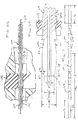
FIG. 1 is an illustration of an example insertion apparatus for introducing the neurovascular device into the microcatheter via the RHV according to aspects of the present invention. -
FIG. 2 is an illustration of another example insertion apparatus for introducing the neurovascular device into the microcatheter via the RHV according to aspects of the present invention. -
FIG. 3 is another illustration of the example insertion apparatus ofFIG. 2 according to aspects of the present invention. -
FIG. 4 is an illustration of yet another example insertion apparatus for introducing the neurovascular device into the microcatheter via the RHV according to aspects of the present invention. -
FIG. 5 is another illustration of the example insertion apparatus ofFIG. 4 according to aspects of the present invention. -
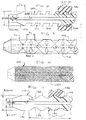
FIG. 6A is an illustration of still another example insertion apparatus for introducing the neurovascular device into the microcatheter via the RHV according to aspects of the present invention. -
FIG. 6B is another illustration of the example insertion apparatus ofFIG. 6A according to aspects of the present invention. -
FIG. 6C is still another illustration of the example insertion apparatus ofFIG. 6A according to aspects of the present invention. -
FIG. 6D is yet another illustration of the example insertion apparatus ofFIG. 6A according to aspects of the present invention. -
FIG. 7 is an additional illustration of the example insertion apparatus ofFIG. 6A according to aspects of the present invention. -
FIG. 8 is an illustration of a further example insertion apparatus for introducing the neurovascular device into the microcatheter via the RHV according to aspects of the present invention. -
FIG. 9 is an illustration of a certain example insertion apparatus for introducing the neurovascular device into the microcatheter via the RHV according to aspects of the present invention. -
FIG. 10 is an illustration of an additional example insertion apparatus for introducing the neurovascular device into the microcatheter via the RHV according to aspects of the present invention. -
FIG. 11 is an illustration of a still further example insertion apparatus for introducing the neurovascular device into the microcatheter via the RHV according to aspects of the present invention. -
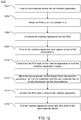
FIG. 12 is a flow chart illustrating steps for introducing the neurovascular device into the microcatheter via the insertion apparatus according to aspects of the present invention. -
FIG. 13 is another flow chart illustrating steps for introducing the neurovascular device into the microcatheter via the RHV according to aspects of the present invention. -
FIG. 14 is yet another flow chart illustrating steps for introducing the neurovascular device into the microcatheter via the RHV according to aspects of the present invention. -
FIG. 15 is still another flow chart illustrating steps for introducing the neurovascular device into the microcatheter via the RHV according to aspects of the present invention. -
FIG. 16 is an additional flow chart illustrating steps for introducing the neurovascular device into the microcatheter via the RHV according to aspects of the present invention. - As used herein, the terms "about" or "approximately" for any numerical values or ranges indicate a suitable dimensional tolerance that allows the part or collection of components to function for its intended purpose as described herein. More specifically, "about" or "approximately" can refer to the range of values ±20% of the recited value, e.g. "about 90%" can refer to the range of values from 71% to 99%.
- An example of an
insertion apparatus 110 is illustrated inFIG. 1 for introducing aneurovascular device 170 into a microcatheter 130 via anRHV 140. The microcatheter 130 can include amicrocatheter shaft 131 and amicrocatheter hub 132 that are all part of the same microcatheter assembly. Examples of theneurovascular device 170 can include, but not limited to, a mechanical thrombectomy device, a neurovascular access device, a neurovascular balloon device, a neurovascular assist device, and a neurovascular clot removal/flow device. - The
insertion apparatus 110 can have a longitudinal body 150. The longitudinal body 150 can define alumen 152 therethrough that allows theneurovascular device 170 to pass through. The longitudinal body 150 can include aproximal portion 154 having a first color and adistal portion 156 having a second color different from the first color. The longitudinal body 150 can include aboundary 158 between theproximal portion 154 and thedistal portion 156. Theboundary 158 can be aligned with aproximal end 160 of anRHV 140 when theinsertion apparatus 110 is correctly positioned relative to the microcatheter 130 and theRHV 140, when the microcatheter 130 is coupled to theRHV 140. - Each end of the
insertion apparatus 110 can be dyed a different color. This color change can allow the physician to know when theinsertion apparatus 110 has been correctly positioned into themicrocatheter hub 132. During loading, the physician can see if theinsertion apparatus 110 begins to slip out of location based on color change. The color change can signify correct seating. - Another example of an
insertion apparatus 210 is illustrated inFIG. 2 for introducing aneurovascular device 270 into amicrocatheter 230 via anRHV 240. Theinsertion apparatus 210 can include alongitudinal body 250 defining alumen 252 therethrough that allows theneurovascular device 270 to pass through. Theinsertion apparatus 210 can include aledge 254 disposed on anouter surface 256 of thelongitudinal body 250. Before introducing theneurovascular device 250 into themicrocatheter 230, themicrocatheter 230 can be first coupled to theRHV 240. When theinsertion apparatus 210 is correctly positioned relative to themicrocatheter 230 and theRHV 240 for introducing theneurovascular device 270 into themicrocatheter 230, theledge 254 can prevent a complete entry of theinsertion apparatus 210 into aproximal end 260 of theRHV 240, when theledge 254 is aligned with theproximal end 260 of theRHV 240. - As illustrated in
FIG. 2 , theledge 254 can include a width "W" greater than a diameter "d" of anopening 262 of theproximal end 260 of theRHV 240. The diameter "d" of theopening 262 can allow a partial entry of theinsertion apparatus 210 into theproximal end 260 of theRHV 240. - In one example as illustrated in
FIG. 3 , theledge 254 can be disposed towards adistal end 272 of thelongitudinal body 250. Asecond ledge 258 can be disposed towards aproximal end 274 of thelongitudinal body 250. As such, the ledge can be positioned at each end of theinsertion apparatus 210 to allow the physician to know when theinsertion apparatus 210 has been correctly seated in themicrocatheter hub 232. During loading, the physician can see if theinsertion apparatus 210 begins to slip out of location when theledge ledges RHV 240. - Yet another example of an
insertion apparatus 410 is illustrated inFIG. 4 for introducing aneurovascular device 470 into amicrocatheter 430 via anRHV 440. Theinsertion apparatus 410 can include alongitudinal body 450. Thelongitudinal body 450 can include alumen 452 therethrough that allows theneurovascular device 470 to pass through. Thelongitudinal body 450 can include a tapereddistal portion 456 sized to allow partial entry into aproximal end 432 of amicrocatheter shaft 431. - In one example as illustrated in
FIG. 5 , the tapereddistal portion 456 can include an outer diameter "d1" sized to prevent complete deployment into themicrocatheter 430. - In one example, the outer diameter "d1" can be about less than 0.021 inches, while an inner diameter of the
microcatheter 430 can be approximately 0.021 inches or greater, so that theinsertion apparatus 410 can be inserted into themicrocatheter 430. - In one example, the tapered
distal portion 456 can have a length "TL" of approximately 10mm. - In one example as seen in
FIG. 5 , thelongitudinal body 450 can include a taperedproximal portion 458. - The
insertion apparatus 450 can be tapered on each end so that that each end can have an outer diameter "d1" less than 0.021 inches to allow it to sit inside a lumen of themicrocatheter 430. This can prevent theinsertion apparatus 410 being inadvertently deployed in the microcatheter hub. - Referring to
FIG. 5 , theinsertion apparatus 410 can have a length "L" in a range between approximately 410mm and approximately 600mm. Thelongitudinal body - A still another example of an
insertion apparatus FIGS. 6A-11 for introducing aneurovascular device 670 into a microcatheter 630 via anRHV 640. Theinsertion apparatus 610 can include alongitudinal body longitudinal body lumen neurovascular device 670 to pass through. The longitudinal body can include an unevenouter surface insertion apparatus 610 from the microcatheter 630 when introducing theneurovascular device 670 into the microcatheter 630. -
FIG. 6B can represent a longitudinal cross section of a full assembly of theinsertion apparatus 610, the microcatheter 630 and theneurovascular device 670. As illustrated inFIG. 6B , theneurovascular device 670 can move forward into amicrocatheter shaft 631 in a direction as represented by an arrow "F". InFIG. 6B , a shaded or hatched region enclosing themicrocatheter shaft 631 and themicrocatheter hub 632 can represent amicrocatheter hub wall 633. As seen inFIG. 6B , themicrocatheter shaft 631 can define amicrocatheter shaft lumen 634 for receiving theneurovascular device 670. - In one example as illustrated in
FIG. 6D , theinsertion apparatus 610 can define alumen 652 therein for accommodating theneurovascular device 670. Thelumen 652 can have an inner diameter of about 0.024 inches. - The
insertion apparatus outer surface RHV seal insertion apparatus microcatheter hub 632, therefore significantly reducing the possibility of a failed introduction or premature deployment of theneurovascular device 670. - In one example, a
distal portion 656 of thelongitudinal body 650 can include adistalmost taper 671 to allow thedistal portion 656 to advance partially into the microcatheter 630. As shown inFIG. 6D , thedistalmost taper 671 can form an angle θ in a range of approximately 10°-20° with respect to a longitudinal axis "A" of theinsertion apparatus 610. Thedistalmost taper 671 can enable a distal tip of theinsertion apparatus 610 to further advance into themicrocatheter hub 632. Thedistalmost taper 671 can allow theinsertion apparatus 610 to advance to a most distal end of themicrocatheter hub 632, therefore significantly reducing the possibility of a failed delivery of theneurovascular device 670 into the microcatheter 630, which can otherwise occur due to a geometry of themicrocatheter hub 632 or a partial deployment of theneurovascular device 670 in themicrocatheter hub 632. - In one example, with reference to
FIG. 7 , thelongitudinal body 650 can have a proximal most taper 673. Thedistalmost taper 671 and the proximal most taper 673 each can have a length "TL" greater than 8.5mm. In one example, the length "TL" can be approximately 10mm. Each of thedistalmost taper 671 and the proximal most taper 673 can taper from a maximum outer diameter of approximately 0.045 inches to a minimum outer diameter of approximately 0.035 inches as illustrated inFIGS. 6D ,8 and 11 . - In one example, the uneven
outer surface seal RHV 640. - In one example, the uneven
outer surface 654 can include a plurality oftapers outer surface 654 to reduce movement of theinsertion apparatus 610 during introduction of theneurovascular device 670 into the microcatheter 630. The plurality oftapers tapers 672 inclined in a first direction at a first side of theinsertion apparatus 610, and a second plurality oftapers 674 inclined in a second direction at a second side of the insertion apparatus. The second direction can be opposite from the first direction. Thetapers - In one example, the
tapers 672 can be positioned at a distal end of theinsertion apparatus 610, whiletapers 674 can be positioned at a proximal end of theinsertion apparatus 610. As illustrated inFIG. 7 , the taper directions oftapers insertion apparatus 610 can be used either way. - Each of the
tapers distalmost taper 671 or the proximal most taper 673 in order to improve the grip theclosed RHV seal 642 has on theinsertion apparatus 610. - In one example as illustrated in
FIG. 6C , when theRHV seal 642 closes on theinsertion apparatus 610, tapers 672 or tapers 674 can be locked or gripped by theRHV seal 642 or embedded into theRHV seal 642 to provide additional grip, preventing theinsertion apparatus 610 from backing out ofRHV 640 during device delivery. TheRHV seal 642 can close tight to the insertion apparatus outer diameter. TheRHV seal 642 can deform to form a tight grip on the outer surface of theinsertion apparatus 610. TheRHV seal 642 can deflect to conform with the outer surface of theinsertion apparatus 610. At this point, theRHV seal 642 can be tightened down onto theinsertion apparatus 610 to aid holding it in place in the microcatheter hub. As a result, theinsertion apparatus 610 can be prevented from backing out of theRHV 640 when introducing theneurovascular device 670 into the microcatheter 630. - With reference to
FIG. 6C , tapers 672 or 674 can prevent theinsertion apparatus 610 moving backwards in a direction as represented by an arrow "B" when introducing theneurovascular device 670 into themicrocatheter shaft 631. - With reference to
FIGS. 6D ,8 and 11 , when theRHV seal 642 closes on theinsertion apparatus 610, theRHV seal 642 can deform around theinsertion apparatus 610 to form a firm grip on theinsertion apparatus 610. As a result, theRHV seal 642 can prevent theinsertion apparatus 610 from backing out of theRHV 640 when introducing theneurovascular device 670 into themicrocatheter shaft 631. - In one example as illustrated in
FIG. 8 , theRHV 640 can include aseal 842. Theseal 842 can include arecess 844 formed in theseal 842. The unevenouter surface 854 can include at least one threadedextrusion 856 engaging with therecess 844 formed in theseal 842 of theRHV 640. - In one example, the threaded
extrusion 856 can include a thickness "T1" less than a width "W1" of therecess 844 formed in theseal 842 of theRHV 640. - In one example as illustrated in
FIG. 9 , laser engraved pattern on an outer surface of theinsertion apparatus 910 can improve RHV grip, preventing movement. The unevenouter surface 954 can include a plurality ofprotrusions 980. At least oneprotrusion 980 can include a length "PL" from about 2mm to about 3mm. The length "PL" can be slightly small than an approximate size of the RHV seal. - Referring to
FIG. 8 , the threadedextrusion 856 can be formed along the outer surface of the insertion apparatus to improve tightness between the RHV seal and the insertion apparatus when the RHV seal grips the insertion apparatus. - In one example as illustrated in
FIG. 10 , the unevenouter surface 1054 can include a knurled surface to improve RHV grip. - In one example as illustrated in
FIG. 11 , the unevenouter surface 1154 can include awave pattern 1160 along a length of thelongitudinal body 1150 to improve grip of RHV on the insertion apparatus. TheRHV seal 1142 can include arecess 1144. The recess 114 can include acomplementary profile 1170 engaging with the unevenouter surface 1154. TheRHV seal 1142 can be closed tight to theinsertion apparatus 1110. TheRHV seal 1142 is deformable to conform with thewave pattern 1160. -
FIG. 12 is a flow diagram illustrating anexample method 1200 for inserting theneurovascular device 670 into the microcatheter 630. Themethod 1200 can include one or more of the following steps presented in no particular order. - At
step 1202, theneurovascular device 670 can be loaded into theinsertion apparatus 610. - At
step 1204, theRHV 640 can be attached to themicrocatheter hub 632. A physician can apply theRHV 640 to themicrocatheter hub 632 before inserting theinsertion apparatus 610 into the microcatheter 630. In one example, in order to ensure that the below designs work correctly theRHV 640 of a specific length must be provided. - At
step 1206, theinsertion apparatus 610, with theneurovascular device 670 preloaded therein, can be introduced into theRHV 640. - At
step 1208, theinsertion apparatus 610 can be positioned tight against aproximal end 635 of amicrocatheter shaft 631 as illustrated inFIG. 6B . - At
step 1210, theRHV seal 642 can be closed down on theinsertion apparatus 610 to hold theinsertion apparatus 610 in place. - At
step 1212, theneurovascular device 670 can be moved forward from theinsertion apparatus 610 into the microcatheter 630 until theneurovascular device 670 is fully introduced into the microcatheter 630. - At
step 1214, once theneurovascular device 670 is fully introduced into the microcatheter 630, theRHV seal 642 can be loosened in order to remove theinsertion apparatus 670. - At
step 1216, theinsertion apparatus 670 can be pulled proximally off ashaft 675 of theneurovascular device 670. -
FIG. 13 is another flow diagram illustrating anexample method 1300 for inserting theneurovascular device 170 into the microcatheter 130 via theRHV 140. Themethod 1300 can include one or more of the following steps presented in no particular order. - At
step 1302, theRHV 140 can be applied to the microcatheter 130. - At
step 1304, theinsertion apparatus 110 can be inserted into the microcatheter 130 through theRHV 140. - At
step 1306, theboundary 158 between theproximal portion 154 and thedistal portion 156 of theinsertion apparatus 110 can be matched with theproximal end 160 of theRHV 140. Theproximal portion 154 can include a first color. Thedistal portion 156 can include a second color different from the first color. - At
step 1308, theneurovascular device 170 can be inserted into the microcatheter 130 through thelumen 152 defined in theinsertion apparatus 110. -
FIG. 14 is yet another flow diagram illustrating anexample method 1400 for inserting theneurovascular device 270 into themicrocatheter 230 via theRHV 240. Themethod 1400 can include one or more of the following steps presented in no particular order. - At
step 1402, theRHV 240 can be applied to themicrocatheter 230. - At
step 1404, theinsertion apparatus 210 can be inserted into themicrocatheter 230 through theRHV 240. - At
step 1406, theledge 254 disposed on theouter surface 256 of thelongitudinal body 250 of theinsertion apparatus 210 can be contacted to theproximal end 260 of theRHV 240. - At
step 1408, theneurovascular device 270 can be inserted into themicrocatheter 230 through thelumen 252 defined in theinsertion apparatus 210. - In one example, the
ledge 254 can have a width "W" greater than a diameter "d" of theopening 262 of theproximal end 260 of theRHV 240, allowing a partial entry of theinsertion apparatus 210 into theproximal end 260 of theRHV 240 based on the diameter "d" of theopening 262. -
FIG. 15 is a flow diagram illustrating anexample method 1500 for introducing theneurovascular device 470 into themicrocatheter 430 via theRHV 440. Themethod 1500 can include one or more of the following steps presented in no particular order. - At
step 1502, theRHV 440 can be applied to themicrocatheter 430. - At
step 1504, the tapereddistal portion 456 of theinsertion apparatus 410 can be inserted into theproximal end 432 of themicrocatheter shaft 431 through theRHV 440. - At
step 1506, the tapereddistal portion 456 can be configured to restrict full insertion of the tapereddistal portion 456 into themicrocatheter 430. - At
step 1508, theneurovascular device 470 can be inserted into themicrocatheter 430 through thelumen 452 defined in theinsertion apparatus 410. -
FIG. 16 is a flow diagram illustrating anexample method 1600 for introducing theneurovascular device 670 into the microcatheter 630 via theRHV 640. Themethod 1600 can include one or more of the following steps presented in no particular order. - At
step 1602, theRHV 640 can be applied to the microcatheter 630. - At
step 1604, thelongitudinal body insertion apparatus RHV 640. - At
step 1606, a backward movement of theinsertion apparatus neurovascular device 670 into the microcatheter 630 using the unevenouter surface longitudinal body - At
step 1608, theneurovascular device 670 can be inserted into the microcatheter 630 through thelumen insertion apparatus - Any of the
example methods - In one embodiment, the insertion apparatus may have a spiral profile. Both ends of the insertion apparatus may have a tapered profile to enhance ease of use and microcatheter capability.
- The descriptions contained herein are examples of embodiments of the invention and are not intended in any way to limit the scope of the invention. As described herein, the invention contemplates many variations and modifications of the insertion apparatus. These modifications would be apparent to those having ordinary skill in the art to which this invention relates and are intended to be within the scope of the claims which follow.
Claims (15)
- An insertion apparatus for introducing a neurovascular device into a microcatheter via an RHV, comprising:a longitudinal body defining a lumen therethrough that allows the neurovascular device to pass through,a ledge disposed on an outer surface of the longitudinal body that prevents a complete entry of the insertion apparatus into a proximal end of the RHV, when the ledge is aligned with the proximal end of the RHV, the insertion apparatus is correctly positioned relative to the microcatheter and the RHV for introducing the neurovascular device into the microcatheter, and the microcatheter is coupled to the RHV
- The insertion apparatus of claim 1, wherein the ledge comprises a width greater than a diameter of an opening of the proximal end of the RHV, the diameter of the opening allows a partial entry of the insertion apparatus into the proximal end of the RHV.
- The insertion apparatus of claim 2, the ledge is disposed towards a distal end of the longitudinal body,
the insertion apparatus comprises a second ledge disposed towards a proximal end of the longitudinal body. - An insertion apparatus for introducing a neurovascular device into a microcatheter via an RHV, comprising:
a longitudinal body comprising:a lumen therethrough that allows the neurovascular device to pass through, anda tapered distal portion sized to allow partial entry into a proximal end of a microcatheter shaft. - The insertion apparatus of claim 4, wherein the tapered distal portion comprises an outer diameter sized to prevent complete deployment into the microcatheter, optionally wherein the outer diameter is about less than 0.021 inches.
- The insertion apparatus of claim 4, wherein the longitudinal body comprises a tapered proximal portion, optionally wherein the tapered distal portion comprises a length of approximately 10mm.
- An insertion apparatus for introducing a neurovascular device into a microcatheter via an RHV, comprising:a longitudinal body defining a lumen therethrough that allows the neurovascular device to pass through, andan uneven outer surface preventing a backward movement of the insertion apparatus from the microcatheter when introducing the neurovascular device into the microcatheter.
- The insertion apparatus of claim 7, wherein a distal portion of the longitudinal body comprises a distalmost taper to allow the distal portion to advance partially into the microcatheter.
- The insertion apparatus of claim 7, the uneven outer surface comprises a sealing relationship with respect to a seal of the RHV
- The insertion apparatus of claim 7, wherein the uneven outer surface defines a plurality of tapers along a length of the longitudinal body to reduce movement of the insertion apparatus during introduction of the neurovascular device into the microcatheter.
- The insertion apparatus of claim 7, wherein the plurality of tapers comprises:a first plurality of tapers inclined in a first direction at a first side of the insertion apparatus, anda second plurality of tapers inclined in a second direction at a second side of the insertion apparatus, the second direction being opposite from the first direction.
- The insertion apparatus of claim 7, wherein the longitudinal body defines a length in a range from about 410mm to about 600mm.
- The insertion apparatus of claim 7, wherein the RHV further comprises:a seal comprising with a recess formed in the seal;the uneven outer surface comprises at least one threaded extrusion engaging with the recess formed in the seal of the RHV
- The insertion apparatus of claim 13, wherein the threaded extrusion comprises a thickness less than a width of the recess formed in the seal of the RHV, optionally wherein the uneven outer surface comprises a plurality of protrusions, at least one protrusion comprises a length from about 2mm to about 3mm.
- The insertion apparatus of claim 7, wherein (i) the uneven outer surface comprises a knurled surface, or (ii) the uneven outer surface comprises a wave pattern along a length of the longitudinal body,
the RHV further comprises a recess of a seal comprising a complementary profile engaging with the uneven outer surface.
Applications Claiming Priority (1)
| Application Number | Priority Date | Filing Date | Title |
|---|---|---|---|
| US201962951742P | 2019-12-20 | 2019-12-20 |
Publications (3)
| Publication Number | Publication Date |
|---|---|
| EP3848081A1 true EP3848081A1 (en) | 2021-07-14 |
| EP3848081B1 EP3848081B1 (en) | 2025-02-26 |
| EP3848081C0 EP3848081C0 (en) | 2025-02-26 |
Family
ID=73855732
Family Applications (1)
| Application Number | Title | Priority Date | Filing Date |
|---|---|---|---|
| EP20215379.7A Active EP3848081B1 (en) | 2019-12-20 | 2020-12-18 | Neurovascular insertion tool |
Country Status (6)
| Country | Link |
|---|---|
| US (1) | US11992643B2 (en) |
| EP (1) | EP3848081B1 (en) |
| JP (1) | JP7663173B2 (en) |
| KR (1) | KR20210081268A (en) |
| CN (1) | CN113143400A (en) |
| ES (1) | ES3021334T3 (en) |
Families Citing this family (5)
| Publication number | Priority date | Publication date | Assignee | Title |
|---|---|---|---|---|
| US12285182B2 (en) | 2018-10-10 | 2025-04-29 | Innova Vascular, Inc. | Devices and methods for removing an embolus |
| CN115460999A (en) | 2020-03-04 | 2022-12-09 | 施菲姆德控股有限责任公司 | Thrombus removal systems and related methods |
| US12599397B2 (en) | 2021-05-19 | 2026-04-14 | Shifamed Holdings, Llc | Thrombus removal systems and associated methods |
| US20230381482A1 (en) * | 2022-05-31 | 2023-11-30 | Neuravi Limited | Introducer Tool for an Aspiration Catheter |
| CN116138716B (en) * | 2023-04-21 | 2023-09-12 | 首都医科大学宣武医院 | Imaging catheter and intravascular imaging system |
Citations (2)
| Publication number | Priority date | Publication date | Assignee | Title |
|---|---|---|---|---|
| EP0761250A1 (en) * | 1995-08-31 | 1997-03-12 | Target Therapeutics, Inc. | Bi-directional catheter |
| US20020165536A1 (en) * | 2000-03-31 | 2002-11-07 | Medtronic, Inc. | Method and system for delivery of a medical electrical lead within a venous system |
Family Cites Families (16)
| Publication number | Priority date | Publication date | Assignee | Title |
|---|---|---|---|---|
| JPH1119217A (en) * | 1997-07-04 | 1999-01-26 | Olympus Optical Co Ltd | Medical guide wire |
| WO2004026385A1 (en) * | 2002-09-20 | 2004-04-01 | I.S.T Corporation | Medical guide wire and process for production thereof |
| WO2004041329A2 (en) * | 2002-11-01 | 2004-05-21 | C.R. Bard, Inc. | Low profile short tapered tip catheter |
| US7220269B1 (en) * | 2003-11-06 | 2007-05-22 | Possis Medical, Inc. | Thrombectomy catheter system with occluder and method of using same |
| US8500785B2 (en) * | 2004-07-13 | 2013-08-06 | Boston Scientific Scimed, Inc. | Catheter |
| US8021420B2 (en) * | 2009-03-12 | 2011-09-20 | Medtronic Vascular, Inc. | Prosthetic valve delivery system |
| US8764779B2 (en) * | 2010-05-13 | 2014-07-01 | Rex Medical, L.P. | Rotational thrombectomy wire |
| CA2824058A1 (en) * | 2011-01-10 | 2012-07-19 | Spotlight Technology Partners Llc | Apparatus and methods for accessing and treating a body cavity, lumen, or ostium |
| JP5925093B2 (en) * | 2012-02-10 | 2016-05-25 | テルモ株式会社 | Direction changing device and medical device assembly including the same |
| US9138221B2 (en) * | 2012-09-20 | 2015-09-22 | Medos International Sarl | Anti-backup suture anchor |
| CN202892007U (en) * | 2012-10-29 | 2013-04-24 | 上海形状记忆合金材料有限公司 | Stopper intervening transport device |
| US9539022B2 (en) * | 2012-11-28 | 2017-01-10 | Microvention, Inc. | Matter conveyance system |
| EP2745869A1 (en) * | 2012-12-21 | 2014-06-25 | ECP Entwicklungsgesellschaft mbH | Sluice assembly for the introduction of a cord-like body, in particular of a catheter, into a patient |
| WO2018071691A1 (en) * | 2016-10-12 | 2018-04-19 | Boston Scientific Scimed, Inc. | Thrombectomy catheter |
| EP4134120A1 (en) * | 2017-01-10 | 2023-02-15 | Route 92 Medical, Inc. | Aspiration catheter systems |
| CN109247959B (en) * | 2017-07-13 | 2020-07-03 | 先健科技(深圳)有限公司 | Plugging device pushing device and conveying system |
-
2020
- 2020-12-11 US US17/119,601 patent/US11992643B2/en active Active
- 2020-12-18 ES ES20215379T patent/ES3021334T3/en active Active
- 2020-12-18 EP EP20215379.7A patent/EP3848081B1/en active Active
- 2020-12-18 JP JP2020210015A patent/JP7663173B2/en active Active
- 2020-12-18 CN CN202011508037.7A patent/CN113143400A/en active Pending
- 2020-12-18 KR KR1020200178192A patent/KR20210081268A/en active Pending
Patent Citations (2)
| Publication number | Priority date | Publication date | Assignee | Title |
|---|---|---|---|---|
| EP0761250A1 (en) * | 1995-08-31 | 1997-03-12 | Target Therapeutics, Inc. | Bi-directional catheter |
| US20020165536A1 (en) * | 2000-03-31 | 2002-11-07 | Medtronic, Inc. | Method and system for delivery of a medical electrical lead within a venous system |
Also Published As
| Publication number | Publication date |
|---|---|
| JP7663173B2 (en) | 2025-04-16 |
| EP3848081B1 (en) | 2025-02-26 |
| KR20210081268A (en) | 2021-07-01 |
| CN113143400A (en) | 2021-07-23 |
| US20210187264A1 (en) | 2021-06-24 |
| JP2021098014A (en) | 2021-07-01 |
| ES3021334T3 (en) | 2025-05-26 |
| US11992643B2 (en) | 2024-05-28 |
| EP3848081C0 (en) | 2025-02-26 |
Similar Documents
| Publication | Publication Date | Title |
|---|---|---|
| US11992643B2 (en) | Neurovascular insertion tool | |
| US8043263B2 (en) | Slittable delivery device assembly for the delivery of a cardiac surgical device | |
| US6074381A (en) | Cylindrical roller stent crimper apparatus with radiation shield | |
| US8850676B2 (en) | Guidewire loading tool for a catheter | |
| CA2328798C (en) | Needle safety device | |
| US20190105471A1 (en) | Sheath assembly for insertion of a cord-shaped element, particularly a catheter, into the body of a patient | |
| US4969875A (en) | Drainage device for medical use | |
| CA2514036A1 (en) | Catheter design that facilitates positioning at tissue to be diagnosed or treated | |
| JP5248659B2 (en) | Dilator device for ventricular puncture | |
| US20100094225A1 (en) | Slittable delivery device for the delivery of a cardiac surgical device | |
| CN105338876B (en) | Spiral element and gatherer | |
| JP2007252960A (en) | Protector for balloon catheter | |
| JP4489219B2 (en) | Balloon catheter protection | |
| JP2011120760A (en) | Indwelling needle | |
| US7273491B2 (en) | Means and method for treating an intimal dissection after stent implantation | |
| US20200069154A1 (en) | Endoscopic puncture needle | |
| US11129517B2 (en) | Endoscopic treatment tool | |
| US20220080163A1 (en) | Balloon catheter | |
| CN116115402B (en) | A proximal end structure of a conveyor and a conveying system | |
| GB2447328A (en) | An orthopaedic jig having releasably held sliding pins | |
| US20180256237A1 (en) | Catheter sleeve for cryotherapy system | |
| JP6672604B2 (en) | Tube stent | |
| CN112040895B (en) | Disposal Systems and Casings | |
| EP3936089A1 (en) | Stent delivery system | |
| FR2607707A1 (en) | Removable base for catheter and catheter fitted thereto |
Legal Events
| Date | Code | Title | Description |
|---|---|---|---|
| PUAI | Public reference made under article 153(3) epc to a published international application that has entered the european phase |
Free format text: ORIGINAL CODE: 0009012 |
|
| STAA | Information on the status of an ep patent application or granted ep patent |
Free format text: STATUS: THE APPLICATION HAS BEEN PUBLISHED |
|
| AK | Designated contracting states |
Kind code of ref document: A1 Designated state(s): AL AT BE BG CH CY CZ DE DK EE ES FI FR GB GR HR HU IE IS IT LI LT LU LV MC MK MT NL NO PL PT RO RS SE SI SK SM TR |
|
| STAA | Information on the status of an ep patent application or granted ep patent |
Free format text: STATUS: REQUEST FOR EXAMINATION WAS MADE |
|
| 17P | Request for examination filed |
Effective date: 20211208 |
|
| RBV | Designated contracting states (corrected) |
Designated state(s): AL AT BE BG CH CY CZ DE DK EE ES FI FR GB GR HR HU IE IS IT LI LT LU LV MC MK MT NL NO PL PT RO RS SE SI SK SM TR |
|
| STAA | Information on the status of an ep patent application or granted ep patent |
Free format text: STATUS: EXAMINATION IS IN PROGRESS |
|
| 17Q | First examination report despatched |
Effective date: 20220408 |
|
| GRAP | Despatch of communication of intention to grant a patent |
Free format text: ORIGINAL CODE: EPIDOSNIGR1 |
|
| STAA | Information on the status of an ep patent application or granted ep patent |
Free format text: STATUS: GRANT OF PATENT IS INTENDED |
|
| INTG | Intention to grant announced |
Effective date: 20240419 |
|
| GRAJ | Information related to disapproval of communication of intention to grant by the applicant or resumption of examination proceedings by the epo deleted |
Free format text: ORIGINAL CODE: EPIDOSDIGR1 |
|
| STAA | Information on the status of an ep patent application or granted ep patent |
Free format text: STATUS: EXAMINATION IS IN PROGRESS |
|
| INTC | Intention to grant announced (deleted) | ||
| GRAP | Despatch of communication of intention to grant a patent |
Free format text: ORIGINAL CODE: EPIDOSNIGR1 |
|
| STAA | Information on the status of an ep patent application or granted ep patent |
Free format text: STATUS: GRANT OF PATENT IS INTENDED |
|
| INTG | Intention to grant announced |
Effective date: 20240927 |
|
| GRAS | Grant fee paid |
Free format text: ORIGINAL CODE: EPIDOSNIGR3 |
|
| GRAA | (expected) grant |
Free format text: ORIGINAL CODE: 0009210 |
|
| STAA | Information on the status of an ep patent application or granted ep patent |
Free format text: STATUS: THE PATENT HAS BEEN GRANTED |
|
| AK | Designated contracting states |
Kind code of ref document: B1 Designated state(s): AL AT BE BG CH CY CZ DE DK EE ES FI FR GB GR HR HU IE IS IT LI LT LU LV MC MK MT NL NO PL PT RO RS SE SI SK SM TR |
|
| REG | Reference to a national code |
Ref country code: GB Ref legal event code: FG4D |
|
| REG | Reference to a national code |
Ref country code: CH Ref legal event code: EP |
|
| REG | Reference to a national code |
Ref country code: DE Ref legal event code: R096 Ref document number: 602020046688 Country of ref document: DE |
|
| REG | Reference to a national code |
Ref country code: IE Ref legal event code: FG4D |
|
| U01 | Request for unitary effect filed |
Effective date: 20250320 |
|
| U07 | Unitary effect registered |
Designated state(s): AT BE BG DE DK EE FI FR IT LT LU LV MT NL PT RO SE SI Effective date: 20250326 |
|
| REG | Reference to a national code |
Ref country code: ES Ref legal event code: FG2A Ref document number: 3021334 Country of ref document: ES Kind code of ref document: T3 Effective date: 20250526 |
|
| PG25 | Lapsed in a contracting state [announced via postgrant information from national office to epo] |
Ref country code: RS Free format text: LAPSE BECAUSE OF FAILURE TO SUBMIT A TRANSLATION OF THE DESCRIPTION OR TO PAY THE FEE WITHIN THE PRESCRIBED TIME-LIMIT Effective date: 20250526 |
|
| PG25 | Lapsed in a contracting state [announced via postgrant information from national office to epo] |
Ref country code: PL Free format text: LAPSE BECAUSE OF FAILURE TO SUBMIT A TRANSLATION OF THE DESCRIPTION OR TO PAY THE FEE WITHIN THE PRESCRIBED TIME-LIMIT Effective date: 20250226 |
|
| PG25 | Lapsed in a contracting state [announced via postgrant information from national office to epo] |
Ref country code: NO Free format text: LAPSE BECAUSE OF FAILURE TO SUBMIT A TRANSLATION OF THE DESCRIPTION OR TO PAY THE FEE WITHIN THE PRESCRIBED TIME-LIMIT Effective date: 20250526 Ref country code: IS Free format text: LAPSE BECAUSE OF FAILURE TO SUBMIT A TRANSLATION OF THE DESCRIPTION OR TO PAY THE FEE WITHIN THE PRESCRIBED TIME-LIMIT Effective date: 20250626 |
|
| PG25 | Lapsed in a contracting state [announced via postgrant information from national office to epo] |
Ref country code: HR Free format text: LAPSE BECAUSE OF FAILURE TO SUBMIT A TRANSLATION OF THE DESCRIPTION OR TO PAY THE FEE WITHIN THE PRESCRIBED TIME-LIMIT Effective date: 20250226 |
|
| PG25 | Lapsed in a contracting state [announced via postgrant information from national office to epo] |
Ref country code: GR Free format text: LAPSE BECAUSE OF FAILURE TO SUBMIT A TRANSLATION OF THE DESCRIPTION OR TO PAY THE FEE WITHIN THE PRESCRIBED TIME-LIMIT Effective date: 20250527 |
|
| PG25 | Lapsed in a contracting state [announced via postgrant information from national office to epo] |
Ref country code: SM Free format text: LAPSE BECAUSE OF FAILURE TO SUBMIT A TRANSLATION OF THE DESCRIPTION OR TO PAY THE FEE WITHIN THE PRESCRIBED TIME-LIMIT Effective date: 20250226 |
|
| PG25 | Lapsed in a contracting state [announced via postgrant information from national office to epo] |
Ref country code: CZ Free format text: LAPSE BECAUSE OF FAILURE TO SUBMIT A TRANSLATION OF THE DESCRIPTION OR TO PAY THE FEE WITHIN THE PRESCRIBED TIME-LIMIT Effective date: 20250226 |
|
| PG25 | Lapsed in a contracting state [announced via postgrant information from national office to epo] |
Ref country code: SK Free format text: LAPSE BECAUSE OF FAILURE TO SUBMIT A TRANSLATION OF THE DESCRIPTION OR TO PAY THE FEE WITHIN THE PRESCRIBED TIME-LIMIT Effective date: 20250226 |
|
| U20 | Renewal fee for the european patent with unitary effect paid |
Year of fee payment: 6 Effective date: 20251110 |
|
| PLBE | No opposition filed within time limit |
Free format text: ORIGINAL CODE: 0009261 |
|
| STAA | Information on the status of an ep patent application or granted ep patent |
Free format text: STATUS: NO OPPOSITION FILED WITHIN TIME LIMIT |
|
| PGFP | Annual fee paid to national office [announced via postgrant information from national office to epo] |
Ref country code: IE Payment date: 20251111 Year of fee payment: 6 |
|
| 26N | No opposition filed |
Effective date: 20251127 |
|
| PGFP | Annual fee paid to national office [announced via postgrant information from national office to epo] |
Ref country code: ES Payment date: 20260114 Year of fee payment: 6 |