EP3847980A1 - Extractor cannula securement and processing - Google Patents
Extractor cannula securement and processing Download PDFInfo
- Publication number
- EP3847980A1 EP3847980A1 EP21151225.6A EP21151225A EP3847980A1 EP 3847980 A1 EP3847980 A1 EP 3847980A1 EP 21151225 A EP21151225 A EP 21151225A EP 3847980 A1 EP3847980 A1 EP 3847980A1
- Authority
- EP
- European Patent Office
- Prior art keywords
- wire
- elongated member
- loop
- wires
- distal end
- Prior art date
- Legal status (The legal status is an assumption and is not a legal conclusion. Google has not performed a legal analysis and makes no representation as to the accuracy of the status listed.)
- Granted
Links
Images




Classifications
-
- A—HUMAN NECESSITIES
- A61—MEDICAL OR VETERINARY SCIENCE; HYGIENE
- A61B—DIAGNOSIS; SURGERY; IDENTIFICATION
- A61B17/00—Surgical instruments, devices or methods
- A61B17/22—Implements for squeezing-off ulcers or the like on inner organs of the body; Implements for scraping-out cavities of body organs, e.g. bones; for invasive removal or destruction of calculus using mechanical vibrations; for removing obstructions in blood vessels, not otherwise provided for
- A61B17/221—Gripping devices in the form of loops or baskets for gripping calculi or similar types of obstructions
-
- A—HUMAN NECESSITIES
- A61—MEDICAL OR VETERINARY SCIENCE; HYGIENE
- A61B—DIAGNOSIS; SURGERY; IDENTIFICATION
- A61B17/00—Surgical instruments, devices or methods
- A61B17/22—Implements for squeezing-off ulcers or the like on inner organs of the body; Implements for scraping-out cavities of body organs, e.g. bones; for invasive removal or destruction of calculus using mechanical vibrations; for removing obstructions in blood vessels, not otherwise provided for
- A61B17/221—Gripping devices in the form of loops or baskets for gripping calculi or similar types of obstructions
- A61B2017/2212—Gripping devices in the form of loops or baskets for gripping calculi or similar types of obstructions having a closed distal end, e.g. a loop
Definitions
- Urological baskets, and other baskets often utilize a glue joint to secure the basket formation into the desired orientation. It is desired to use other methods to construct a stone management basket such as for the benefits of limiting the cost, both in labor and in material, to manufacture a stone management basket as well as for repeatability and other quality control factors.
- Embodiments of the present disclosure relate to, among other things, securement and processing of medical retrieval devices.
- Each of the embodiments disclosed herein may include one or more of the features described in connection with any of the other disclosed embodiments.
- One general aspect of the present disclosure includes a medical retrieval device for retrieving stones, calculi, and the like, as well as polyps, foreign objects, and/or anatomical abnormalities from various organs and passages, comprising an elongated member, and a first wire and a second wire that forms a retrieval basket.
- the elongated member has a hollow passageway longitudinally positioned therebetween, and the first wire having first and second ends attached to the distal end of the elongated member and forming a first loop extending longitudinally and distally from said distal end of the elongated member.
- the second wire likewise has its first and second ends attached to the distal end of the elongated member, forming a second loop extending longitudinally and distally from the distal end of the elongated member.
- the second loop is interconnected distally to said first loop, which interconnection may include one or more of conjoined loops, cannula, weld, solder, or other connection means known in the art for the distal end of wire baskets.
- the elongated member and the first and second wires are secured by a crimp joint and a second joint, where such joints can be secured by a cannula, welding, and/or soldering in addition to and/or instead of crimping.
- Another general aspect of the present disclosure includes processing of the device disclosed above, processing comprising steps of placing all ends of the first wire and the second wire into an elongated member through a distal end of the elongated member, moving said elongated member to a position where the first loop and the second loop start their curvatures, placing said first and second wires and said elongated member through an alignment fixture such as a crimping or other securement fixture having thru cuts configured for the interlocked wires, aligning said elongated member in a desired position, and crimping said first and second wires and said elongated member, where such joints can be secured by a cannula, welding (including laser welding), glue, and/or soldering in addition to and/or instead of crimping.
- processing comprising steps of placing all ends of the first wire and the second wire into an elongated member through a distal end of the elongated member, moving said elongated member to a position where the first loop and the second loop start their cur
- proximal and distal are used herein to refer to the relative positions of the components of an exemplary medical device.
- proximal refers to a position relatively closer to the exterior of the body or closer to a medical professional using the medical device.
- distal refers to a position relatively further away from the medical professional using the medical device, or closer to the interior of the body.
- a retrieval device 10 may comprise an elongated member 20 (such as, for example, a cannula), a retrieval basket 30, a crimp joint 50 and an additional/second joint 40.
- the elongated member 20 may generally comprise a proximal end 22, a distal end 28, and a hollow passageway 25 longitudinally positioned therebetween.
- the elongated member 20 may be made of a metal such as stainless steel. Other flexible or rigid materials may also be utilized.
- the retrieval basket 30 may comprise a plurality of wires 34, 38 attached to the distal end 28 of the elongated member 20.
- the basket may include multiple loops of wires that interact with each other in order to be used in a stone management clinical setting, or for other retrieval uses when deployed a patient.
- the term "loop" should be understood to encompass a variety of shapes and not merely a circular or elliptical configuration, but also - by way of non-limiting example, helical, diamond-shaped, and/or other wire-shapes capable of defining a central volume to capture and/or carry a stone or other material.
- the basket can be preformed into any desired shape or size for capturing and removing calculi from the biliary or urinary system. Dimensions should be on scale with the size of the retrieval device. For example, the diameter of the device 10 may range from 1.5Fr to 4.5Fr.
- the wires 34, 38 may be made from a nickel titanium alloy such as nitinol. As illustrated by FIG. 3 , in one embodiment, the basket 30 may comprise two wires 34, 38, each forming loops extending longitudinally and distally from the distal end of the elongated member 28. In some embodiments, the wires 34, 38 may be interconnected perpendicularly relative to each other at the distal end and/or along planes defined by the respective loop formed by each wire 34, 38. In one embodiment, the large loop of wire 38 includes a distal-end small loop 39 that interconnects/ links in a chain-like manner with a distal-end small loop 35 of the wire 34. Alternative embodiments may include different wire geometries (e.g. pie wire, round, square, D-shaped, etc.), wire quantities, and/or cannula geometries.
- wire geometries e.g. pie wire, round, square, D-shaped, etc.
- the second joint 40 may be an adhesive such as glue.
- the adhesive may temporarily or permanently secure the wires 34, 38.
- low viscosity cyanoacrylate glue such as Loctite 4061
- glue properties and application parameters should be selected to ensure appropriate adhesive dispersion.
- a notchless cannula design may be advantageous to provide additional surface area for gluing and crimping.
- the second joint 40 may be a heat shrink.
- a heat shrink which may be activated using a heat gun, would have a melting temperature lower than the temperature at which the wires 34, 38 are formed (roughly 400°C) so that the wires 34, 38 are not adversely affected during the heat shrink process.
- Exemplary heat shrink materials may include PTFE and PEBAX.
- processing of the retrieval device may generally include placing all four ends of the wires 34, 38 into the elongated member 20 through its hollow passageway 25, moving the elongated member 20 to the bottom of the wires 33, 37 where the wires 34, 38 end their curvature and go straight. Then, the wires 34, 38 and the elongated member 20 may be placed through an alignment fixture or other securement fixture such as crimping fixture 100 having thru cuts configured for the interlocked wires 34, 38 to ensure that the wires 34, 38 are aligned properly. Once the wires 34, 38 and the elongated member 20 are properly aligned, they may be crimped to form a crimp joint 50. A second joint 40 may be formed prior to forming the crimp joint 50.
- formation of a crimp joint 50 may utilize a crimping fixture or other alignment fixture 100 to ensure that the wires 34, 38 hold their desired relationship during the crimping process.
- crimping fixture or other alignment fixture 100a, 100b, 200 has a cross-hair thru cut 150, 250 all the way through the part to allow a distal or proximal end of the basket 30 to be fed through it before and/or after crimping.
- crimping fixture 100a, 100b, 200 may have a blind cut (not shown in figures) instead of thru cut 150, 200. Referring to FIGS.
- crimping fixture 100a, 100b, 200 may have a thru cut 150, 250 that slides in the wires 34, 38 interconnected perpendicularly.
- configurations illustrated in FIGS. 4A-4B have an indented area 110a, 110b in the middle to help the basket wires 34, 38 slide into the fixture.
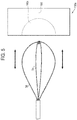
- FIG. 5 illustrates how wires 34, 38 may interact with crimping fixture 100a. Indented area 110a may help wires 34, 38 to slide all the way into the fixture 100a through the thru cut 150.
- Other crimping fixtures as illustrated by FIG. 4B-4B may interact with wires 34, 38 in a similar manner. More specifically, the fixture of FIG.
- crimping fixture 200 may comprise a base section 210 and an elongated section 230 to help get the fixture 200 closer to the crimping site. Specifically, the diameter of the base section 210 may be greater than the diameter of the elongated section 230.
- the diameter of the base section 210 may be 0.750 inches while the diameter of the elongated section 250 may be 0.375 inches.
- the thickness of base section 210 may be 0.157 inches.
- the thickness of the elongated section 250 may range from 0.079 inches to 0.154 inches.
- the crimping fixture 200 may also have the thru cut 250. As with alternative embodiment described above, the thru cut 250 should have a tight tolerance to keep the wires 34, 38 in line. Specific dimensions should be on scale with the size of the retrieval device 10, thus may vary.
- processing of a device with a glue 40a or other secondary securement means (such as, by way of non-limiting example, weld or solder) 40a as part of a second joint 40 may include steps of aligning the wires 34, 38 inside an elongated member 20 to ensure that the wires 34, 38 are shaped correctly to form a basket of a desired configuration. Aligning may include pulling the wires 34, 38 into an alignment sheath (not shown) to assure a proper alignment and then removing the alignment sheath while maintaining the alignment. After removing the alignment sheath, the glue may be applied to the distal end 28 of the elongated member 20 or elsewhere within the elongated member 20.
- a sheath 46 may be pulled over the elongated member 20 before or after the act of crimping.
- the proximal half of the elongated member 20, where no glue 40a presents may be crimped with the wires 34, 38. But, this crimp 50 and/or additional crimp joints 50 may be placed as needed or desired, proximal and/or distal of the glue or other secondary securement means in embodiments were such secondary securement means are present.
- Processing an embodiment using a heat shrink as an elongated body 20 may comprise steps of placing all ends of the wires 34, 38 in a heat shrink, moving the heat shrink (20) to the wires' bottom portions 33, 37 where the wires 34, 38 end their curvature and go straight or substantially straight as compared to the loop portions. Further, processing may include turning a heat gun to a desired temperature, placing all ends of the wires 34, 38 and the heat shrink at a desired distance from the heat gun for a designated time. Once the heat shrink and the wires 34, 38 cool down and an inspection confirms a proper alignment, which may be perpendicular, one may proceed to further process the device 10.
- a short crimper that can crimp down to 0.010" at a force greater than 100 lbs. may be used to form a crimp joint 50. It is important to ensure that the pressure setting for the crimping fixture is set to the correct final outside diameter and that the pressure is high enough.
- the area of crimp joint 50 after crimping with a short crimper may have a hexagonally shaped cross-section, or another geometric shape (e.g., octagonal, circular, elliptical, or other shape, depending upon the shape of the crimping mechanism/surface contacting the crimp joint 50 during formation thereof, with reference to non-limiting examples in FIGS.
- the region near and/or including the crimp joint 50 may have different cross-sectional configurations (as viewed along line X-X of FIG. 6 ) after the wires are aligned and secured together.
- Certain embodiments, such as FIGS. 7A, 7D, 7E, and 7F may advantageously include a pie-shaped wire, also called “delta wire", because the added angles may help keep the wires 34, 38 in the perpendicular relationship.
- a medical retrieval device for retrieving stones, calculi, and the like from various organs and passages may comprising an elongated member, and a first wire and a second wire that forms a retrieval basket.
- the wires forming the basket and the elongated member may be secured by a crimp joint and a second joint.
- Processing of the device may include placing all ends of the first wire and the second wire into an elongated member through a distal end of the elongated member, moving said elongated member to a position where the first loop and the second loop start their curvatures, placing said first and second wires and said elongated member through a crimping fixture having thru cuts configured for the interlocked wires, aligning said elongated member in a desired position, and crimping said first and second wires and said elongated member.
Landscapes
- Health & Medical Sciences (AREA)
- Surgery (AREA)
- Life Sciences & Earth Sciences (AREA)
- Heart & Thoracic Surgery (AREA)
- Nuclear Medicine, Radiotherapy & Molecular Imaging (AREA)
- Vascular Medicine (AREA)
- Engineering & Computer Science (AREA)
- Biomedical Technology (AREA)
- Orthopedic Medicine & Surgery (AREA)
- Medical Informatics (AREA)
- Molecular Biology (AREA)
- Animal Behavior & Ethology (AREA)
- General Health & Medical Sciences (AREA)
- Public Health (AREA)
- Veterinary Medicine (AREA)
- Surgical Instruments (AREA)
Abstract
Description
- This application claims priority to
U.S. Provisional Application Ser. No. 62/960,348, filed January 13, 2020 - Various organs and passages in the body are subject to the development of stones, calculi, and the like. For example, gallstones are a common problem in the United States and the most frequent cause of gallbladder inflammation. Calculi in other parts of the biliary system and/or the urinary system are also common places. Medical retrieval devices for capturing and extracting stones from various organs and passages are well known. Such devices typically comprise a retrieval basket attached to a distal end of an elongated member.
- Urological baskets, and other baskets, often utilize a glue joint to secure the basket formation into the desired orientation. It is desired to use other methods to construct a stone management basket such as for the benefits of limiting the cost, both in labor and in material, to manufacture a stone management basket as well as for repeatability and other quality control factors.
- Embodiments of the present disclosure relate to, among other things, securement and processing of medical retrieval devices. Each of the embodiments disclosed herein may include one or more of the features described in connection with any of the other disclosed embodiments.
- Aspects of the invention are set out in the independent claims and preferred features are set out in the dependent claims. Preferred features of one aspect may be applied to other aspects.
- One general aspect of the present disclosure includes a medical retrieval device for retrieving stones, calculi, and the like, as well as polyps, foreign objects, and/or anatomical abnormalities from various organs and passages, comprising an elongated member, and a first wire and a second wire that forms a retrieval basket. The elongated member has a hollow passageway longitudinally positioned therebetween, and the first wire having first and second ends attached to the distal end of the elongated member and forming a first loop extending longitudinally and distally from said distal end of the elongated member. The second wire likewise has its first and second ends attached to the distal end of the elongated member, forming a second loop extending longitudinally and distally from the distal end of the elongated member. The second loop is interconnected distally to said first loop, which interconnection may include one or more of conjoined loops, cannula, weld, solder, or other connection means known in the art for the distal end of wire baskets. The elongated member and the first and second wires are secured by a crimp joint and a second joint, where such joints can be secured by a cannula, welding, and/or soldering in addition to and/or instead of crimping.
- Another general aspect of the present disclosure includes processing of the device disclosed above, processing comprising steps of placing all ends of the first wire and the second wire into an elongated member through a distal end of the elongated member, moving said elongated member to a position where the first loop and the second loop start their curvatures, placing said first and second wires and said elongated member through an alignment fixture such as a crimping or other securement fixture having thru cuts configured for the interlocked wires, aligning said elongated member in a desired position, and crimping said first and second wires and said elongated member, where such joints can be secured by a cannula, welding (including laser welding), glue, and/or soldering in addition to and/or instead of crimping.
- Other systems, methods, features and advantages of the invention will be, or will become, apparent to one with skill in the art upon examination of the following figures and detailed description. It is intended that all such additional systems, methods, features, and advantages be within the scope of the invention, and be encompassed by the following claims.
- The present disclosure can be better understood with reference to the following drawings and description. The components in the figures are not necessarily to scale, emphasis instead being placed upon illustrating the principles of the present disclosure. Moreover, in the figures, like-referenced numerals designate corresponding parts throughout the different views.
-
FIG. 1 is an illustration showing a distal portion of a retrieval device in accordance with certain non-limiting aspects of the present disclosure, where alternative basket and/or snare configurations may be used with the retrieval device. -
FIG. 2 is an illustration showing an elongated member in accordance with certain aspects of the present disclosure. -
FIG. 3 is an illustration showing a retrieval basket in accordance with certain aspects of the present disclosure. -
FIGS. 4A-4D are illustrations showing various non-limiting crimp or other alignment fixture designs for processing of the device, where other securement means such as a cannula, welding (including laser welding), glue, and/or soldering in addition to and/or instead of crimping may be used. -
FIG. 5 is an illustration showing how wires of the device may interact with, for example, a crimping fixture in accordance with certain aspects of the present disclosure. -
FIG. 6 is an illustration showing assembly of the device in accordance with certain aspects of the present disclosure. -
FIGS. 7A-7F are illustrations showing various cross sectional configurations, taken along line X-X ofFIG. 6 , near a crimp joint as described within the scope of the present disclosure. - Various aspects are described below with reference to the drawings in which like elements generally are identified by like numerals. The relationship and functioning of the various elements of the aspects may better be understood by reference to the following detailed description. However, aspects are not limited to those illustrated in the drawings or explicitly described below. It also should be understood that the drawings are not necessarily to scale, and in certain instances details may have been omitted that are not necessary for an understanding of aspects disclosed herein, such as conventional material, construction, and assembly.
- The terms "proximal" and "distal" are used herein to refer to the relative positions of the components of an exemplary medical device. When used herein, "proximal" refers to a position relatively closer to the exterior of the body or closer to a medical professional using the medical device. In contrast, "distal" refers to a position relatively further away from the medical professional using the medical device, or closer to the interior of the body.
- Referring to
FIG. 1 , aretrieval device 10 may comprise an elongated member 20 (such as, for example, a cannula), aretrieval basket 30, acrimp joint 50 and an additional/second joint 40. As illustrated byFIG. 2 , theelongated member 20 may generally comprise aproximal end 22, adistal end 28, and ahollow passageway 25 longitudinally positioned therebetween. Theelongated member 20 may be made of a metal such as stainless steel. Other flexible or rigid materials may also be utilized. Theretrieval basket 30 may comprise a plurality ofwires distal end 28 of theelongated member 20. The basket may include multiple loops of wires that interact with each other in order to be used in a stone management clinical setting, or for other retrieval uses when deployed a patient. The term "loop" should be understood to encompass a variety of shapes and not merely a circular or elliptical configuration, but also - by way of non-limiting example, helical, diamond-shaped, and/or other wire-shapes capable of defining a central volume to capture and/or carry a stone or other material. The basket can be preformed into any desired shape or size for capturing and removing calculi from the biliary or urinary system. Dimensions should be on scale with the size of the retrieval device. For example, the diameter of thedevice 10 may range from 1.5Fr to 4.5Fr. Thewires FIG. 3 , in one embodiment, thebasket 30 may comprise twowires elongated member 28. In some embodiments, thewires wire wire 38 includes a distal-endsmall loop 39 that interconnects/ links in a chain-like manner with a distal-endsmall loop 35 of thewire 34. Alternative embodiments may include different wire geometries (e.g. pie wire, round, square, D-shaped, etc.), wire quantities, and/or cannula geometries. - In one embodiment, the
second joint 40 may be an adhesive such as glue. The adhesive may temporarily or permanently secure thewires - In another embodiment, the
second joint 40 may be a heat shrink. Ideally, a heat shrink, which may be activated using a heat gun, would have a melting temperature lower than the temperature at which thewires wires wires retrieval device 10. Another advantage of this embodiment is that it may replace the need to use a metal cannula and give the retrieval device 10 a higher degree of flexibility when used inside a scope for a procedure. - In one embodiment, processing of the retrieval device may generally include placing all four ends of the
wires elongated member 20 through itshollow passageway 25, moving theelongated member 20 to the bottom of thewires wires wires elongated member 20 may be placed through an alignment fixture or other securement fixture such as crimpingfixture 100 having thru cuts configured for the interlockedwires wires wires elongated member 20 are properly aligned, they may be crimped to form a crimp joint 50. A second joint 40 may be formed prior to forming the crimp joint 50. - In one embodiment, formation of a crimp joint 50 may utilize a crimping fixture or
other alignment fixture 100 to ensure that thewires other alignment fixture cut basket 30 to be fed through it before and/or after crimping. Alternatively, crimpingfixture cut FIGS. 4A-4D , crimpingfixture cut wires FIGS. 4A-4B have anindented area basket wires FIG. 5 illustrates howwires fixture 100a.Indented area 110a may helpwires fixture 100a through the thrucut 150. Other crimping fixtures as illustrated byFIG. 4B-4B may interact withwires FIG. 4A hasopenings 120 on the side to allow assembly with screws (screws not shown in figures). The fixture ofFIG. 4B , the fixture does not haveopenings 120 on the side for screw assembly, but instead has smaller area outside of theindented area 110b. The thrucut 150 should have a tight tolerance to keep thewires cuts 150 may be 0.590 inches and 0.020 inches, respectively. As illustrated byFIGS. 4C and 4D , in another embodiment, crimpingfixture 200 may comprise abase section 210 and anelongated section 230 to help get thefixture 200 closer to the crimping site. Specifically, the diameter of thebase section 210 may be greater than the diameter of theelongated section 230. For example, the diameter of thebase section 210 may be 0.750 inches while the diameter of theelongated section 250 may be 0.375 inches. Further, the thickness ofbase section 210 may be 0.157 inches. The thickness of theelongated section 250 may range from 0.079 inches to 0.154 inches. The crimpingfixture 200 may also have the thrucut 250. As with alternative embodiment described above, the thrucut 250 should have a tight tolerance to keep thewires retrieval device 10, thus may vary. - Referring to
FIG. 6 , processing of a device with aglue 40a or other secondary securement means (such as, by way of non-limiting example, weld or solder) 40a as part of a second joint 40 may include steps of aligning thewires elongated member 20 to ensure that thewires wires distal end 28 of theelongated member 20 or elsewhere within theelongated member 20. Once theglue 40a cures, asheath 46 may be pulled over theelongated member 20 before or after the act of crimping. As shown in the drawings, the proximal half of theelongated member 20, where noglue 40a presents, may be crimped with thewires crimp 50 and/or additional crimp joints 50 may be placed as needed or desired, proximal and/or distal of the glue or other secondary securement means in embodiments were such secondary securement means are present. - Processing an embodiment using a heat shrink as an
elongated body 20 may comprise steps of placing all ends of thewires bottom portions wires wires wires device 10. - In another embodiment, a short crimper that can crimp down to 0.010" at a force greater than 100 lbs. may be used to form a crimp joint 50. It is important to ensure that the pressure setting for the crimping fixture is set to the correct final outside diameter and that the pressure is high enough. The area of crimp joint 50 after crimping with a short crimper may have a hexagonally shaped cross-section, or another geometric shape (e.g., octagonal, circular, elliptical, or other shape, depending upon the shape of the crimping mechanism/surface contacting the crimp joint 50 during formation thereof, with reference to non-limiting examples in
FIGS. 7A-7F , where "geometric" is defined as "utilizing rectilinear or simple curvilinear motifs or outlines that bear little resemblance to natural/organic forms"). In some embodiments, as illustrated byFIGS. 7A-7F , the region near and/or including the crimp joint 50 may have different cross-sectional configurations (as viewed along line X-X ofFIG. 6 ) after the wires are aligned and secured together. Certain embodiments, such asFIGS. 7A, 7D, 7E, and 7F , may advantageously include a pie-shaped wire, also called "delta wire", because the added angles may help keep thewires - In summary, there is disclosed a medical retrieval device for retrieving stones, calculi, and the like from various organs and passages may comprising an elongated member, and a first wire and a second wire that forms a retrieval basket. The wires forming the basket and the elongated member may be secured by a crimp joint and a second joint. Processing of the device may include placing all ends of the first wire and the second wire into an elongated member through a distal end of the elongated member, moving said elongated member to a position where the first loop and the second loop start their curvatures, placing said first and second wires and said elongated member through a crimping fixture having thru cuts configured for the interlocked wires, aligning said elongated member in a desired position, and crimping said first and second wires and said elongated member.
- Although some preferred embodiments of the disclosure have been described, it should be understood that the disclosure is not so limited and modifications may be made without departing from the disclosure. The scope of the invention is defined by the appended claims, and all devices that come within the meaning of the claims, either literally or by equivalence, are intended to be embraced therein.
Claims (15)
- A method of making a medical device having a first wire, a second wire, and an elongated member, comprising the steps of:placing all ends of the first wire and the second wire into an elongated member through a distal end of the elongated member so that the first wire forms a first loop and the second wire forms a second loop;moving said elongated member to a position where the first loop and the second loop start their curvatures;placing said first and second wires and said elongated member through an alignment fixture having thru cuts configured for the wires;aligning said elongated member in a desired position; andcrimping said first and second wires and said elongated member.
- The method of claim 1, further comprising:forming a first loop with a first wire;forming a second loop with a second wire; anddistally interlocking the second wire to said first loop prior to placing all ends of the first wire and the second wire into an elongated member through a distal end of the elongated member.
- The method of claim 2, further comprising configuring said first wire and said second wire perpendicularly.
- The method of claim 1 or 2, wherein the alignment fixture further has a longitudinally elongated section that allows the fixture to get closer to a crimping site.
- The method of any of claims 1 to 4, further comprising applying a second securement to the elongated member after placing all ends of the first wire and the second wire into said elongated member through a distal end of said elongated member.
- The method of any of claims 1 to 5, further comprising:placing all ends of the first wire and the second wire into a heat shrink;moving the heat shrink to a position where the first loop and the second loop start their curvatures;heating the heat shrink and all ends of the wires at a desired distance for a designated time; andcooling the heat shrink, the first wire, and the second wire prior to placing all ends of the first wire and the second wire into said elongated member through the distal end of said member.
- The method of any preceding claim, wherein the crimping step includes using a crimper that crimps the elongated member in a geometric shape.
- A medical device comprising:an elongated member having a proximal end, a distal end, and a hollow passageway longitudinally positioned therebetween;a first wire having first and second ends attached to said distal end of said elongated member and forming a first loop extending longitudinally and distally from said distal end of said elongated member; anda second wire having first and second ends attached to said distal end of said elongated member, forming a second loop extending longitudinally and distally from said distal end of said elongated member, and interconnected distally to said first loop;wherein the elongated member and the first and second wires are secured by a securement joint.
- The medical device of claim 8, wherein the securement joint is configured as a crimp joint.
- The medical device of claim 8 or 9, further comprising a second joint.
- The medical device of claim 10, wherein the second joint includes a glue.
- The medical device of claim 10, wherein the second joint includes a heat shrink, solder, and/or weld.
- The medical device of any of claims 8 to 12, wherein the securement joint is, in cross-section, geometrically shaped.
- The medical device of claim 13, where geometric shape is hexagonal or octagonal.
- The medical device of claim any of claims 8 to 12, wherein said first wire and said second wire are interconnected perpendicularly.
Applications Claiming Priority (1)
| Application Number | Priority Date | Filing Date | Title |
|---|---|---|---|
| US202062960348P | 2020-01-13 | 2020-01-13 |
Publications (2)
| Publication Number | Publication Date |
|---|---|
| EP3847980A1 true EP3847980A1 (en) | 2021-07-14 |
| EP3847980B1 EP3847980B1 (en) | 2024-07-24 |
Family
ID=74175684
Family Applications (1)
| Application Number | Title | Priority Date | Filing Date |
|---|---|---|---|
| EP21151225.6A Active EP3847980B1 (en) | 2020-01-13 | 2021-01-12 | Extractor cannula securement and processing |
Country Status (2)
| Country | Link |
|---|---|
| US (2) | US20210212708A1 (en) |
| EP (1) | EP3847980B1 (en) |
Families Citing this family (2)
| Publication number | Priority date | Publication date | Assignee | Title |
|---|---|---|---|---|
| USD943743S1 (en) * | 2019-01-15 | 2022-02-15 | Olympus Corporation | Stone retrieval basket for medical device |
| US12616491B2 (en) | 2023-01-11 | 2026-05-05 | Boston Scientific Scimed, Inc. | Medical devices and related methods thereof |
Citations (4)
| Publication number | Priority date | Publication date | Assignee | Title |
|---|---|---|---|---|
| US5064428A (en) * | 1990-09-18 | 1991-11-12 | Cook Incorporated | Medical retrieval basket |
| US20090030427A1 (en) * | 2002-10-04 | 2009-01-29 | Vance Products Incorporated, D/B/A Cook Urological Incorporated | Handle for interchangeable medical device |
| WO2009121379A1 (en) * | 2008-04-01 | 2009-10-08 | Coloplast A/S | Wire basket unit having fixing disk element |
| DE102012222356A1 (en) * | 2012-12-05 | 2014-06-05 | Epflex Feinwerktechnik Gmbh | Medical safety wire instrument |
Family Cites Families (15)
| Publication number | Priority date | Publication date | Assignee | Title |
|---|---|---|---|---|
| US6159220A (en) * | 1999-03-11 | 2000-12-12 | Scimed Life Systems, Inc. | Medical retrieval device |
| US6676668B2 (en) * | 2001-12-12 | 2004-01-13 | C.R. Baed | Articulating stone basket |
| US9101383B1 (en) * | 2003-04-25 | 2015-08-11 | Annex Medical, Inc. | Medical retrieval device |
| US7731722B2 (en) * | 2003-07-31 | 2010-06-08 | Vance Products Incorporated | Ureteral backstop filter and retrieval device |
| US8523879B1 (en) * | 2005-03-31 | 2013-09-03 | Stuart J. Lind | Stone retriever for flexible endoscopes having small diameter working channels |
| US8206401B2 (en) * | 2005-07-15 | 2012-06-26 | Granit Medical Innovation Llc | Endoscope cutting and retrieving snare instrument |
| GB2448123B (en) * | 2006-07-17 | 2010-05-05 | Paul James Mackenney | Surgical tool and crimper for osteotomy fixation unit manufacture |
| US8518054B2 (en) * | 2006-11-21 | 2013-08-27 | Boston Scientific Scimed, Inc. | Medical retrieval devices |
| US9101342B2 (en) * | 2011-07-22 | 2015-08-11 | Rafic Saleh | Surgical retrieval apparatus and method with semi-rigidly extendable and collapsible basket |
| US20130023893A1 (en) * | 2011-07-22 | 2013-01-24 | Rafic Saleh | Endoscopic surgical retrieval apparatus and method with semi-rigidly extendable and collapsable basket |
| US10029281B2 (en) * | 2013-07-19 | 2018-07-24 | Lumsden Corporation | Wire screenings and a method of forming the same |
| WO2016094229A1 (en) * | 2014-12-10 | 2016-06-16 | Boston Scientific Scimed, Inc. | Tipless retrieval device |
| US11980545B2 (en) * | 2016-05-06 | 2024-05-14 | Transmural Systems Llc | Annuloplasty procedures, related devices and methods |
| WO2018055454A1 (en) * | 2016-09-26 | 2018-03-29 | Besselink Petrus A | Device for delivery and retrieval of protection filters |
| CN121647775A (en) * | 2019-11-22 | 2026-03-13 | 波士顿科学国际有限公司 | Device for tissue removal |
-
2021
- 2021-01-08 US US17/144,459 patent/US20210212708A1/en not_active Abandoned
- 2021-01-12 EP EP21151225.6A patent/EP3847980B1/en active Active
-
2023
- 2023-08-15 US US18/450,204 patent/US20230404608A1/en active Pending
Patent Citations (4)
| Publication number | Priority date | Publication date | Assignee | Title |
|---|---|---|---|---|
| US5064428A (en) * | 1990-09-18 | 1991-11-12 | Cook Incorporated | Medical retrieval basket |
| US20090030427A1 (en) * | 2002-10-04 | 2009-01-29 | Vance Products Incorporated, D/B/A Cook Urological Incorporated | Handle for interchangeable medical device |
| WO2009121379A1 (en) * | 2008-04-01 | 2009-10-08 | Coloplast A/S | Wire basket unit having fixing disk element |
| DE102012222356A1 (en) * | 2012-12-05 | 2014-06-05 | Epflex Feinwerktechnik Gmbh | Medical safety wire instrument |
Also Published As
| Publication number | Publication date |
|---|---|
| EP3847980B1 (en) | 2024-07-24 |
| US20230404608A1 (en) | 2023-12-21 |
| US20210212708A1 (en) | 2021-07-15 |
Similar Documents
| Publication | Publication Date | Title |
|---|---|---|
| US20230404608A1 (en) | Extractor cannula securement and processing | |
| US7789839B2 (en) | Guide wire for use with a catheter | |
| JP6839665B2 (en) | Recovery device and how to use it | |
| US6500182B2 (en) | Minimally-invasive medical retrieval device | |
| EP1656072B1 (en) | Ureteral backstop filter and retrieval device | |
| US10772729B2 (en) | Bone implant | |
| EP2887896B1 (en) | Bone implant | |
| CN120131091A (en) | Coupling joint for a tubular spiral ring of a steerable arm for an endoscope instrument channel | |
| AU2001289110B2 (en) | Minimally-invasive medical retrieval device | |
| EP3041420B1 (en) | Medical retrieval devices | |
| JP2017508486A (en) | Steering tool | |
| KR20090008347A (en) | Systems and Methods for Mechanically Positioning Endovascular Inserts | |
| US11712251B2 (en) | Drill assemblies and methods for drilling into bone | |
| JP6153872B2 (en) | Cannulated guide tool | |
| CN117860384B (en) | Manipulable arm with cords of different sizes and method for producing the same | |
| JP7691072B2 (en) | Composite suture needle having elastically deformable section - Patents.com | |
| US20260002617A1 (en) | Method of manufacturing a tube with a playless hinge and device comprising such a tube | |
| AU2022474277A1 (en) | Vascular access wire tip comprising a crank |
Legal Events
| Date | Code | Title | Description |
|---|---|---|---|
| PUAI | Public reference made under article 153(3) epc to a published international application that has entered the european phase |
Free format text: ORIGINAL CODE: 0009012 |
|
| STAA | Information on the status of an ep patent application or granted ep patent |
Free format text: STATUS: THE APPLICATION HAS BEEN PUBLISHED |
|
| AK | Designated contracting states |
Kind code of ref document: A1 Designated state(s): AL AT BE BG CH CY CZ DE DK EE ES FI FR GB GR HR HU IE IS IT LI LT LU LV MC MK MT NL NO PL PT RO RS SE SI SK SM TR |
|
| STAA | Information on the status of an ep patent application or granted ep patent |
Free format text: STATUS: REQUEST FOR EXAMINATION WAS MADE |
|
| 17P | Request for examination filed |
Effective date: 20220114 |
|
| RBV | Designated contracting states (corrected) |
Designated state(s): AL AT BE BG CH CY CZ DE DK EE ES FI FR GB GR HR HU IE IS IT LI LT LU LV MC MK MT NL NO PL PT RO RS SE SI SK SM TR |
|
| STAA | Information on the status of an ep patent application or granted ep patent |
Free format text: STATUS: EXAMINATION IS IN PROGRESS |
|
| 17Q | First examination report despatched |
Effective date: 20230329 |
|
| GRAP | Despatch of communication of intention to grant a patent |
Free format text: ORIGINAL CODE: EPIDOSNIGR1 |
|
| STAA | Information on the status of an ep patent application or granted ep patent |
Free format text: STATUS: GRANT OF PATENT IS INTENDED |
|
| INTG | Intention to grant announced |
Effective date: 20240313 |
|
| GRAS | Grant fee paid |
Free format text: ORIGINAL CODE: EPIDOSNIGR3 |
|
| GRAA | (expected) grant |
Free format text: ORIGINAL CODE: 0009210 |
|
| STAA | Information on the status of an ep patent application or granted ep patent |
Free format text: STATUS: THE PATENT HAS BEEN GRANTED |
|
| AK | Designated contracting states |
Kind code of ref document: B1 Designated state(s): AL AT BE BG CH CY CZ DE DK EE ES FI FR GB GR HR HU IE IS IT LI LT LU LV MC MK MT NL NO PL PT RO RS SE SI SK SM TR |
|
| REG | Reference to a national code |
Ref country code: GB Ref legal event code: FG4D |
|
| REG | Reference to a national code |
Ref country code: CH Ref legal event code: EP |
|
| P01 | Opt-out of the competence of the unified patent court (upc) registered |
Free format text: CASE NUMBER: APP_39084/2024 Effective date: 20240701 |
|
| REG | Reference to a national code |
Ref country code: IE Ref legal event code: FG4D Ref country code: DE Ref legal event code: R096 Ref document number: 602021015978 Country of ref document: DE |
|
| REG | Reference to a national code |
Ref country code: LT Ref legal event code: MG9D |
|
| REG | Reference to a national code |
Ref country code: NL Ref legal event code: MP Effective date: 20240724 |
|
| PG25 | Lapsed in a contracting state [announced via postgrant information from national office to epo] |
Ref country code: PT Free format text: LAPSE BECAUSE OF FAILURE TO SUBMIT A TRANSLATION OF THE DESCRIPTION OR TO PAY THE FEE WITHIN THE PRESCRIBED TIME-LIMIT Effective date: 20241125 |
|
| REG | Reference to a national code |
Ref country code: AT Ref legal event code: MK05 Ref document number: 1705543 Country of ref document: AT Kind code of ref document: T Effective date: 20240724 |
|
| PG25 | Lapsed in a contracting state [announced via postgrant information from national office to epo] |
Ref country code: NL Free format text: LAPSE BECAUSE OF FAILURE TO SUBMIT A TRANSLATION OF THE DESCRIPTION OR TO PAY THE FEE WITHIN THE PRESCRIBED TIME-LIMIT Effective date: 20240724 |
|
| PG25 | Lapsed in a contracting state [announced via postgrant information from national office to epo] |
Ref country code: PT Free format text: LAPSE BECAUSE OF FAILURE TO SUBMIT A TRANSLATION OF THE DESCRIPTION OR TO PAY THE FEE WITHIN THE PRESCRIBED TIME-LIMIT Effective date: 20241125 Ref country code: NL Free format text: LAPSE BECAUSE OF FAILURE TO SUBMIT A TRANSLATION OF THE DESCRIPTION OR TO PAY THE FEE WITHIN THE PRESCRIBED TIME-LIMIT Effective date: 20240724 |
|
| PG25 | Lapsed in a contracting state [announced via postgrant information from national office to epo] |
Ref country code: NO Free format text: LAPSE BECAUSE OF FAILURE TO SUBMIT A TRANSLATION OF THE DESCRIPTION OR TO PAY THE FEE WITHIN THE PRESCRIBED TIME-LIMIT Effective date: 20241024 |
|
| PG25 | Lapsed in a contracting state [announced via postgrant information from national office to epo] |
Ref country code: FI Free format text: LAPSE BECAUSE OF FAILURE TO SUBMIT A TRANSLATION OF THE DESCRIPTION OR TO PAY THE FEE WITHIN THE PRESCRIBED TIME-LIMIT Effective date: 20240724 Ref country code: GR Free format text: LAPSE BECAUSE OF FAILURE TO SUBMIT A TRANSLATION OF THE DESCRIPTION OR TO PAY THE FEE WITHIN THE PRESCRIBED TIME-LIMIT Effective date: 20241025 Ref country code: PL Free format text: LAPSE BECAUSE OF FAILURE TO SUBMIT A TRANSLATION OF THE DESCRIPTION OR TO PAY THE FEE WITHIN THE PRESCRIBED TIME-LIMIT Effective date: 20240724 |
|
| PG25 | Lapsed in a contracting state [announced via postgrant information from national office to epo] |
Ref country code: BG Free format text: LAPSE BECAUSE OF FAILURE TO SUBMIT A TRANSLATION OF THE DESCRIPTION OR TO PAY THE FEE WITHIN THE PRESCRIBED TIME-LIMIT Effective date: 20240724 |
|
| PG25 | Lapsed in a contracting state [announced via postgrant information from national office to epo] |
Ref country code: LV Free format text: LAPSE BECAUSE OF FAILURE TO SUBMIT A TRANSLATION OF THE DESCRIPTION OR TO PAY THE FEE WITHIN THE PRESCRIBED TIME-LIMIT Effective date: 20240724 |
|
| PG25 | Lapsed in a contracting state [announced via postgrant information from national office to epo] |
Ref country code: AT Free format text: LAPSE BECAUSE OF FAILURE TO SUBMIT A TRANSLATION OF THE DESCRIPTION OR TO PAY THE FEE WITHIN THE PRESCRIBED TIME-LIMIT Effective date: 20240724 Ref country code: IS Free format text: LAPSE BECAUSE OF FAILURE TO SUBMIT A TRANSLATION OF THE DESCRIPTION OR TO PAY THE FEE WITHIN THE PRESCRIBED TIME-LIMIT Effective date: 20241124 |
|
| PG25 | Lapsed in a contracting state [announced via postgrant information from national office to epo] |
Ref country code: HR Free format text: LAPSE BECAUSE OF FAILURE TO SUBMIT A TRANSLATION OF THE DESCRIPTION OR TO PAY THE FEE WITHIN THE PRESCRIBED TIME-LIMIT Effective date: 20240724 |
|
| PG25 | Lapsed in a contracting state [announced via postgrant information from national office to epo] |
Ref country code: ES Free format text: LAPSE BECAUSE OF FAILURE TO SUBMIT A TRANSLATION OF THE DESCRIPTION OR TO PAY THE FEE WITHIN THE PRESCRIBED TIME-LIMIT Effective date: 20240724 Ref country code: RS Free format text: LAPSE BECAUSE OF FAILURE TO SUBMIT A TRANSLATION OF THE DESCRIPTION OR TO PAY THE FEE WITHIN THE PRESCRIBED TIME-LIMIT Effective date: 20241024 |
|
| PG25 | Lapsed in a contracting state [announced via postgrant information from national office to epo] |
Ref country code: RS Free format text: LAPSE BECAUSE OF FAILURE TO SUBMIT A TRANSLATION OF THE DESCRIPTION OR TO PAY THE FEE WITHIN THE PRESCRIBED TIME-LIMIT Effective date: 20241024 Ref country code: PL Free format text: LAPSE BECAUSE OF FAILURE TO SUBMIT A TRANSLATION OF THE DESCRIPTION OR TO PAY THE FEE WITHIN THE PRESCRIBED TIME-LIMIT Effective date: 20240724 Ref country code: NO Free format text: LAPSE BECAUSE OF FAILURE TO SUBMIT A TRANSLATION OF THE DESCRIPTION OR TO PAY THE FEE WITHIN THE PRESCRIBED TIME-LIMIT Effective date: 20241024 Ref country code: LV Free format text: LAPSE BECAUSE OF FAILURE TO SUBMIT A TRANSLATION OF THE DESCRIPTION OR TO PAY THE FEE WITHIN THE PRESCRIBED TIME-LIMIT Effective date: 20240724 Ref country code: IS Free format text: LAPSE BECAUSE OF FAILURE TO SUBMIT A TRANSLATION OF THE DESCRIPTION OR TO PAY THE FEE WITHIN THE PRESCRIBED TIME-LIMIT Effective date: 20241124 Ref country code: HR Free format text: LAPSE BECAUSE OF FAILURE TO SUBMIT A TRANSLATION OF THE DESCRIPTION OR TO PAY THE FEE WITHIN THE PRESCRIBED TIME-LIMIT Effective date: 20240724 Ref country code: GR Free format text: LAPSE BECAUSE OF FAILURE TO SUBMIT A TRANSLATION OF THE DESCRIPTION OR TO PAY THE FEE WITHIN THE PRESCRIBED TIME-LIMIT Effective date: 20241025 Ref country code: FI Free format text: LAPSE BECAUSE OF FAILURE TO SUBMIT A TRANSLATION OF THE DESCRIPTION OR TO PAY THE FEE WITHIN THE PRESCRIBED TIME-LIMIT Effective date: 20240724 Ref country code: ES Free format text: LAPSE BECAUSE OF FAILURE TO SUBMIT A TRANSLATION OF THE DESCRIPTION OR TO PAY THE FEE WITHIN THE PRESCRIBED TIME-LIMIT Effective date: 20240724 Ref country code: BG Free format text: LAPSE BECAUSE OF FAILURE TO SUBMIT A TRANSLATION OF THE DESCRIPTION OR TO PAY THE FEE WITHIN THE PRESCRIBED TIME-LIMIT Effective date: 20240724 Ref country code: AT Free format text: LAPSE BECAUSE OF FAILURE TO SUBMIT A TRANSLATION OF THE DESCRIPTION OR TO PAY THE FEE WITHIN THE PRESCRIBED TIME-LIMIT Effective date: 20240724 |
|
| PG25 | Lapsed in a contracting state [announced via postgrant information from national office to epo] |
Ref country code: SM Free format text: LAPSE BECAUSE OF FAILURE TO SUBMIT A TRANSLATION OF THE DESCRIPTION OR TO PAY THE FEE WITHIN THE PRESCRIBED TIME-LIMIT Effective date: 20240724 Ref country code: RO Free format text: LAPSE BECAUSE OF FAILURE TO SUBMIT A TRANSLATION OF THE DESCRIPTION OR TO PAY THE FEE WITHIN THE PRESCRIBED TIME-LIMIT Effective date: 20240724 Ref country code: DK Free format text: LAPSE BECAUSE OF FAILURE TO SUBMIT A TRANSLATION OF THE DESCRIPTION OR TO PAY THE FEE WITHIN THE PRESCRIBED TIME-LIMIT Effective date: 20240724 |
|
| PG25 | Lapsed in a contracting state [announced via postgrant information from national office to epo] |
Ref country code: EE Free format text: LAPSE BECAUSE OF FAILURE TO SUBMIT A TRANSLATION OF THE DESCRIPTION OR TO PAY THE FEE WITHIN THE PRESCRIBED TIME-LIMIT Effective date: 20240724 |
|
| PG25 | Lapsed in a contracting state [announced via postgrant information from national office to epo] |
Ref country code: CZ Free format text: LAPSE BECAUSE OF FAILURE TO SUBMIT A TRANSLATION OF THE DESCRIPTION OR TO PAY THE FEE WITHIN THE PRESCRIBED TIME-LIMIT Effective date: 20240724 |
|
| REG | Reference to a national code |
Ref country code: DE Ref legal event code: R097 Ref document number: 602021015978 Country of ref document: DE |
|
| PG25 | Lapsed in a contracting state [announced via postgrant information from national office to epo] |
Ref country code: SK Free format text: LAPSE BECAUSE OF FAILURE TO SUBMIT A TRANSLATION OF THE DESCRIPTION OR TO PAY THE FEE WITHIN THE PRESCRIBED TIME-LIMIT Effective date: 20240724 Ref country code: IT Free format text: LAPSE BECAUSE OF FAILURE TO SUBMIT A TRANSLATION OF THE DESCRIPTION OR TO PAY THE FEE WITHIN THE PRESCRIBED TIME-LIMIT Effective date: 20240724 |
|
| PLBE | No opposition filed within time limit |
Free format text: ORIGINAL CODE: 0009261 |
|
| STAA | Information on the status of an ep patent application or granted ep patent |
Free format text: STATUS: NO OPPOSITION FILED WITHIN TIME LIMIT |
|
| 26N | No opposition filed |
Effective date: 20250425 |
|
| REG | Reference to a national code |
Ref country code: CH Ref legal event code: PL |
|
| PG25 | Lapsed in a contracting state [announced via postgrant information from national office to epo] |
Ref country code: SE Free format text: LAPSE BECAUSE OF FAILURE TO SUBMIT A TRANSLATION OF THE DESCRIPTION OR TO PAY THE FEE WITHIN THE PRESCRIBED TIME-LIMIT Effective date: 20240724 |
|
| PG25 | Lapsed in a contracting state [announced via postgrant information from national office to epo] |
Ref country code: MC Free format text: LAPSE BECAUSE OF FAILURE TO SUBMIT A TRANSLATION OF THE DESCRIPTION OR TO PAY THE FEE WITHIN THE PRESCRIBED TIME-LIMIT Effective date: 20240724 Ref country code: LU Free format text: LAPSE BECAUSE OF NON-PAYMENT OF DUE FEES Effective date: 20250112 |
|
| PG25 | Lapsed in a contracting state [announced via postgrant information from national office to epo] |
Ref country code: BE Free format text: LAPSE BECAUSE OF NON-PAYMENT OF DUE FEES Effective date: 20250131 |
|
| PG25 | Lapsed in a contracting state [announced via postgrant information from national office to epo] |
Ref country code: FR Free format text: LAPSE BECAUSE OF NON-PAYMENT OF DUE FEES Effective date: 20250131 |
|
| PG25 | Lapsed in a contracting state [announced via postgrant information from national office to epo] |
Ref country code: CH Free format text: LAPSE BECAUSE OF NON-PAYMENT OF DUE FEES Effective date: 20250131 |
|
| REG | Reference to a national code |
Ref country code: BE Ref legal event code: MM Effective date: 20250131 |
|
| PGFP | Annual fee paid to national office [announced via postgrant information from national office to epo] |
Ref country code: GB Payment date: 20260126 Year of fee payment: 6 |
|
| PGFP | Annual fee paid to national office [announced via postgrant information from national office to epo] |
Ref country code: IE Payment date: 20260120 Year of fee payment: 6 Ref country code: DE Payment date: 20260127 Year of fee payment: 6 |
|
| PG25 | Lapsed in a contracting state [announced via postgrant information from national office to epo] |
Ref country code: CY Free format text: LAPSE BECAUSE OF FAILURE TO SUBMIT A TRANSLATION OF THE DESCRIPTION OR TO PAY THE FEE WITHIN THE PRESCRIBED TIME-LIMIT Effective date: 20240724 |
|
| PG25 | Lapsed in a contracting state [announced via postgrant information from national office to epo] |
Ref country code: TR Free format text: LAPSE BECAUSE OF FAILURE TO SUBMIT A TRANSLATION OF THE DESCRIPTION OR TO PAY THE FEE WITHIN THE PRESCRIBED TIME-LIMIT Effective date: 20240724 |
|
| PG25 | Lapsed in a contracting state [announced via postgrant information from national office to epo] |
Ref country code: LT Free format text: LAPSE BECAUSE OF FAILURE TO SUBMIT A TRANSLATION OF THE DESCRIPTION OR TO PAY THE FEE WITHIN THE PRESCRIBED TIME-LIMIT Effective date: 20240724 |