EP3847510B1 - Valve positioner and diagnostic method - Google Patents
Valve positioner and diagnostic method Download PDFInfo
- Publication number
- EP3847510B1 EP3847510B1 EP19858562.2A EP19858562A EP3847510B1 EP 3847510 B1 EP3847510 B1 EP 3847510B1 EP 19858562 A EP19858562 A EP 19858562A EP 3847510 B1 EP3847510 B1 EP 3847510B1
- Authority
- EP
- European Patent Office
- Prior art keywords
- valve
- fault
- control
- simulation model
- physical
- Prior art date
- Legal status (The legal status is an assumption and is not a legal conclusion. Google has not performed a legal analysis and makes no representation as to the accuracy of the status listed.)
- Active
Links
Images


Classifications
-
- G—PHYSICS
- G05—CONTROLLING; REGULATING
- G05B—CONTROL OR REGULATING SYSTEMS IN GENERAL; FUNCTIONAL ELEMENTS OF SUCH SYSTEMS; MONITORING OR TESTING ARRANGEMENTS FOR SUCH SYSTEMS OR ELEMENTS
- G05B23/00—Testing or monitoring of control systems or parts thereof
- G05B23/02—Electric testing or monitoring
- G05B23/0205—Electric testing or monitoring by means of a monitoring system capable of detecting and responding to faults
- G05B23/0259—Electric testing or monitoring by means of a monitoring system capable of detecting and responding to faults characterized by the response to fault detection
- G05B23/0283—Predictive maintenance, e.g. involving the monitoring of a system and, based on the monitoring results, taking decisions on the maintenance schedule of the monitored system; Estimating remaining useful life [RUL]
-
- F—MECHANICAL ENGINEERING; LIGHTING; HEATING; WEAPONS; BLASTING
- F16—ENGINEERING ELEMENTS AND UNITS; GENERAL MEASURES FOR PRODUCING AND MAINTAINING EFFECTIVE FUNCTIONING OF MACHINES OR INSTALLATIONS; THERMAL INSULATION IN GENERAL
- F16K—VALVES; TAPS; COCKS; ACTUATING-FLOATS; DEVICES FOR VENTING OR AERATING
- F16K31/00—Actuating devices; Operating means; Releasing devices
- F16K31/12—Actuating devices; Operating means; Releasing devices actuated by fluid
- F16K31/16—Actuating devices; Operating means; Releasing devices actuated by fluid with a mechanism, other than pulling-or pushing-rod, between fluid motor and closure member
- F16K31/163—Actuating devices; Operating means; Releasing devices actuated by fluid with a mechanism, other than pulling-or pushing-rod, between fluid motor and closure member the fluid acting on a piston
- F16K31/1635—Actuating devices; Operating means; Releasing devices actuated by fluid with a mechanism, other than pulling-or pushing-rod, between fluid motor and closure member the fluid acting on a piston for rotating valves
-
- F—MECHANICAL ENGINEERING; LIGHTING; HEATING; WEAPONS; BLASTING
- F16—ENGINEERING ELEMENTS AND UNITS; GENERAL MEASURES FOR PRODUCING AND MAINTAINING EFFECTIVE FUNCTIONING OF MACHINES OR INSTALLATIONS; THERMAL INSULATION IN GENERAL
- F16K—VALVES; TAPS; COCKS; ACTUATING-FLOATS; DEVICES FOR VENTING OR AERATING
- F16K37/00—Special means in or on valves or other cut-off apparatus for indicating or recording operation thereof, or for enabling an alarm to be given
- F16K37/0075—For recording or indicating the functioning of a valve in combination with test equipment
- F16K37/0083—For recording or indicating the functioning of a valve in combination with test equipment by measuring valve parameters
-
- F—MECHANICAL ENGINEERING; LIGHTING; HEATING; WEAPONS; BLASTING
- F15—FLUID-PRESSURE ACTUATORS; HYDRAULICS OR PNEUMATICS IN GENERAL
- F15B—SYSTEMS ACTING BY MEANS OF FLUIDS IN GENERAL; FLUID-PRESSURE ACTUATORS, e.g. SERVOMOTORS; DETAILS OF FLUID-PRESSURE SYSTEMS, NOT OTHERWISE PROVIDED FOR
- F15B19/00—Testing; Calibrating; Fault detection or monitoring; Simulation or modelling of fluid-pressure systems or apparatus not otherwise provided for
- F15B19/005—Fault detection or monitoring
-
- F—MECHANICAL ENGINEERING; LIGHTING; HEATING; WEAPONS; BLASTING
- F15—FLUID-PRESSURE ACTUATORS; HYDRAULICS OR PNEUMATICS IN GENERAL
- F15B—SYSTEMS ACTING BY MEANS OF FLUIDS IN GENERAL; FLUID-PRESSURE ACTUATORS, e.g. SERVOMOTORS; DETAILS OF FLUID-PRESSURE SYSTEMS, NOT OTHERWISE PROVIDED FOR
- F15B19/00—Testing; Calibrating; Fault detection or monitoring; Simulation or modelling of fluid-pressure systems or apparatus not otherwise provided for
- F15B19/007—Simulation or modelling
-
- F—MECHANICAL ENGINEERING; LIGHTING; HEATING; WEAPONS; BLASTING
- F16—ENGINEERING ELEMENTS AND UNITS; GENERAL MEASURES FOR PRODUCING AND MAINTAINING EFFECTIVE FUNCTIONING OF MACHINES OR INSTALLATIONS; THERMAL INSULATION IN GENERAL
- F16K—VALVES; TAPS; COCKS; ACTUATING-FLOATS; DEVICES FOR VENTING OR AERATING
- F16K31/00—Actuating devices; Operating means; Releasing devices
- F16K31/12—Actuating devices; Operating means; Releasing devices actuated by fluid
-
- F—MECHANICAL ENGINEERING; LIGHTING; HEATING; WEAPONS; BLASTING
- F16—ENGINEERING ELEMENTS AND UNITS; GENERAL MEASURES FOR PRODUCING AND MAINTAINING EFFECTIVE FUNCTIONING OF MACHINES OR INSTALLATIONS; THERMAL INSULATION IN GENERAL
- F16K—VALVES; TAPS; COCKS; ACTUATING-FLOATS; DEVICES FOR VENTING OR AERATING
- F16K31/00—Actuating devices; Operating means; Releasing devices
- F16K31/12—Actuating devices; Operating means; Releasing devices actuated by fluid
- F16K31/16—Actuating devices; Operating means; Releasing devices actuated by fluid with a mechanism, other than pulling-or pushing-rod, between fluid motor and closure member
- F16K31/165—Actuating devices; Operating means; Releasing devices actuated by fluid with a mechanism, other than pulling-or pushing-rod, between fluid motor and closure member the fluid acting on a diaphragm
- F16K31/1655—Actuating devices; Operating means; Releasing devices actuated by fluid with a mechanism, other than pulling-or pushing-rod, between fluid motor and closure member the fluid acting on a diaphragm for rotating valves
-
- F—MECHANICAL ENGINEERING; LIGHTING; HEATING; WEAPONS; BLASTING
- F16—ENGINEERING ELEMENTS AND UNITS; GENERAL MEASURES FOR PRODUCING AND MAINTAINING EFFECTIVE FUNCTIONING OF MACHINES OR INSTALLATIONS; THERMAL INSULATION IN GENERAL
- F16K—VALVES; TAPS; COCKS; ACTUATING-FLOATS; DEVICES FOR VENTING OR AERATING
- F16K37/00—Special means in or on valves or other cut-off apparatus for indicating or recording operation thereof, or for enabling an alarm to be given
- F16K37/0025—Electrical or magnetic means
-
- F—MECHANICAL ENGINEERING; LIGHTING; HEATING; WEAPONS; BLASTING
- F16—ENGINEERING ELEMENTS AND UNITS; GENERAL MEASURES FOR PRODUCING AND MAINTAINING EFFECTIVE FUNCTIONING OF MACHINES OR INSTALLATIONS; THERMAL INSULATION IN GENERAL
- F16K—VALVES; TAPS; COCKS; ACTUATING-FLOATS; DEVICES FOR VENTING OR AERATING
- F16K37/00—Special means in or on valves or other cut-off apparatus for indicating or recording operation thereof, or for enabling an alarm to be given
- F16K37/0075—For recording or indicating the functioning of a valve in combination with test equipment
-
- G—PHYSICS
- G05—CONTROLLING; REGULATING
- G05B—CONTROL OR REGULATING SYSTEMS IN GENERAL; FUNCTIONAL ELEMENTS OF SUCH SYSTEMS; MONITORING OR TESTING ARRANGEMENTS FOR SUCH SYSTEMS OR ELEMENTS
- G05B13/00—Adaptive control systems, i.e. systems automatically adjusting themselves to have a performance which is optimum according to some preassigned criterion
- G05B13/02—Adaptive control systems, i.e. systems automatically adjusting themselves to have a performance which is optimum according to some preassigned criterion electric
- G05B13/04—Adaptive control systems, i.e. systems automatically adjusting themselves to have a performance which is optimum according to some preassigned criterion electric involving the use of models or simulators
-
- G—PHYSICS
- G05—CONTROLLING; REGULATING
- G05B—CONTROL OR REGULATING SYSTEMS IN GENERAL; FUNCTIONAL ELEMENTS OF SUCH SYSTEMS; MONITORING OR TESTING ARRANGEMENTS FOR SUCH SYSTEMS OR ELEMENTS
- G05B17/00—Systems involving the use of models or simulators of said systems
- G05B17/02—Systems involving the use of models or simulators of said systems electric
-
- G—PHYSICS
- G05—CONTROLLING; REGULATING
- G05B—CONTROL OR REGULATING SYSTEMS IN GENERAL; FUNCTIONAL ELEMENTS OF SUCH SYSTEMS; MONITORING OR TESTING ARRANGEMENTS FOR SUCH SYSTEMS OR ELEMENTS
- G05B23/00—Testing or monitoring of control systems or parts thereof
- G05B23/02—Electric testing or monitoring
- G05B23/0205—Electric testing or monitoring by means of a monitoring system capable of detecting and responding to faults
- G05B23/0218—Electric testing or monitoring by means of a monitoring system capable of detecting and responding to faults characterised by the fault detection method dealing with either existing or incipient faults
-
- G—PHYSICS
- G05—CONTROLLING; REGULATING
- G05B—CONTROL OR REGULATING SYSTEMS IN GENERAL; FUNCTIONAL ELEMENTS OF SUCH SYSTEMS; MONITORING OR TESTING ARRANGEMENTS FOR SUCH SYSTEMS OR ELEMENTS
- G05B23/00—Testing or monitoring of control systems or parts thereof
- G05B23/02—Electric testing or monitoring
- G05B23/0205—Electric testing or monitoring by means of a monitoring system capable of detecting and responding to faults
- G05B23/0218—Electric testing or monitoring by means of a monitoring system capable of detecting and responding to faults characterised by the fault detection method dealing with either existing or incipient faults
- G05B23/0243—Electric testing or monitoring by means of a monitoring system capable of detecting and responding to faults characterised by the fault detection method dealing with either existing or incipient faults model based detection method, e.g. first-principles knowledge model
-
- G—PHYSICS
- G05—CONTROLLING; REGULATING
- G05B—CONTROL OR REGULATING SYSTEMS IN GENERAL; FUNCTIONAL ELEMENTS OF SUCH SYSTEMS; MONITORING OR TESTING ARRANGEMENTS FOR SUCH SYSTEMS OR ELEMENTS
- G05B23/00—Testing or monitoring of control systems or parts thereof
- G05B23/02—Electric testing or monitoring
- G05B23/0205—Electric testing or monitoring by means of a monitoring system capable of detecting and responding to faults
- G05B23/0218—Electric testing or monitoring by means of a monitoring system capable of detecting and responding to faults characterised by the fault detection method dealing with either existing or incipient faults
- G05B23/0243—Electric testing or monitoring by means of a monitoring system capable of detecting and responding to faults characterised by the fault detection method dealing with either existing or incipient faults model based detection method, e.g. first-principles knowledge model
- G05B23/0245—Electric testing or monitoring by means of a monitoring system capable of detecting and responding to faults characterised by the fault detection method dealing with either existing or incipient faults model based detection method, e.g. first-principles knowledge model based on a qualitative model, e.g. rule based; if-then decisions
-
- G—PHYSICS
- G05—CONTROLLING; REGULATING
- G05D—SYSTEMS FOR CONTROLLING OR REGULATING NON-ELECTRIC VARIABLES
- G05D3/00—Control of position or direction
- G05D3/12—Control of position or direction using feedback
- G05D3/20—Control of position or direction using feedback using a digital comparing device
-
- G—PHYSICS
- G05—CONTROLLING; REGULATING
- G05D—SYSTEMS FOR CONTROLLING OR REGULATING NON-ELECTRIC VARIABLES
- G05D7/00—Control of flow
- G05D7/005—Control of flow characterised by the use of auxiliary non-electric power combined with the use of electric means
-
- F—MECHANICAL ENGINEERING; LIGHTING; HEATING; WEAPONS; BLASTING
- F15—FLUID-PRESSURE ACTUATORS; HYDRAULICS OR PNEUMATICS IN GENERAL
- F15B—SYSTEMS ACTING BY MEANS OF FLUIDS IN GENERAL; FLUID-PRESSURE ACTUATORS, e.g. SERVOMOTORS; DETAILS OF FLUID-PRESSURE SYSTEMS, NOT OTHERWISE PROVIDED FOR
- F15B13/00—Details of servomotor systems ; Valves for servomotor systems
- F15B13/02—Fluid distribution or supply devices characterised by their adaptation to the control of servomotors
- F15B13/04—Fluid distribution or supply devices characterised by their adaptation to the control of servomotors for use with a single servomotor
- F15B13/042—Fluid distribution or supply devices characterised by their adaptation to the control of servomotors for use with a single servomotor operated by fluid pressure
- F15B13/043—Fluid distribution or supply devices characterised by their adaptation to the control of servomotors for use with a single servomotor operated by fluid pressure with electrically-controlled pilot valves
- F15B13/0433—Fluid distribution or supply devices characterised by their adaptation to the control of servomotors for use with a single servomotor operated by fluid pressure with electrically-controlled pilot valves the pilot valves being pressure control valves
-
- F—MECHANICAL ENGINEERING; LIGHTING; HEATING; WEAPONS; BLASTING
- F15—FLUID-PRESSURE ACTUATORS; HYDRAULICS OR PNEUMATICS IN GENERAL
- F15B—SYSTEMS ACTING BY MEANS OF FLUIDS IN GENERAL; FLUID-PRESSURE ACTUATORS, e.g. SERVOMOTORS; DETAILS OF FLUID-PRESSURE SYSTEMS, NOT OTHERWISE PROVIDED FOR
- F15B20/00—Safety arrangements for fluid actuator systems; Applications of safety devices in fluid actuator systems; Emergency measures for fluid actuator systems
- F15B20/004—Fluid pressure supply failure
-
- F—MECHANICAL ENGINEERING; LIGHTING; HEATING; WEAPONS; BLASTING
- F15—FLUID-PRESSURE ACTUATORS; HYDRAULICS OR PNEUMATICS IN GENERAL
- F15B—SYSTEMS ACTING BY MEANS OF FLUIDS IN GENERAL; FLUID-PRESSURE ACTUATORS, e.g. SERVOMOTORS; DETAILS OF FLUID-PRESSURE SYSTEMS, NOT OTHERWISE PROVIDED FOR
- F15B20/00—Safety arrangements for fluid actuator systems; Applications of safety devices in fluid actuator systems; Emergency measures for fluid actuator systems
- F15B20/005—Leakage; Spillage; Hose burst
-
- F—MECHANICAL ENGINEERING; LIGHTING; HEATING; WEAPONS; BLASTING
- F15—FLUID-PRESSURE ACTUATORS; HYDRAULICS OR PNEUMATICS IN GENERAL
- F15B—SYSTEMS ACTING BY MEANS OF FLUIDS IN GENERAL; FLUID-PRESSURE ACTUATORS, e.g. SERVOMOTORS; DETAILS OF FLUID-PRESSURE SYSTEMS, NOT OTHERWISE PROVIDED FOR
- F15B20/00—Safety arrangements for fluid actuator systems; Applications of safety devices in fluid actuator systems; Emergency measures for fluid actuator systems
- F15B20/008—Valve failure
-
- F—MECHANICAL ENGINEERING; LIGHTING; HEATING; WEAPONS; BLASTING
- F15—FLUID-PRESSURE ACTUATORS; HYDRAULICS OR PNEUMATICS IN GENERAL
- F15B—SYSTEMS ACTING BY MEANS OF FLUIDS IN GENERAL; FLUID-PRESSURE ACTUATORS, e.g. SERVOMOTORS; DETAILS OF FLUID-PRESSURE SYSTEMS, NOT OTHERWISE PROVIDED FOR
- F15B2211/00—Circuits for servomotor systems
- F15B2211/30—Directional control
- F15B2211/31—Directional control characterised by the positions of the valve element
- F15B2211/3144—Directional control characterised by the positions of the valve element the positions being continuously variable, e.g. as realised by proportional valves
-
- F—MECHANICAL ENGINEERING; LIGHTING; HEATING; WEAPONS; BLASTING
- F15—FLUID-PRESSURE ACTUATORS; HYDRAULICS OR PNEUMATICS IN GENERAL
- F15B—SYSTEMS ACTING BY MEANS OF FLUIDS IN GENERAL; FLUID-PRESSURE ACTUATORS, e.g. SERVOMOTORS; DETAILS OF FLUID-PRESSURE SYSTEMS, NOT OTHERWISE PROVIDED FOR
- F15B2211/00—Circuits for servomotor systems
- F15B2211/30—Directional control
- F15B2211/32—Directional control characterised by the type of actuation
- F15B2211/329—Directional control characterised by the type of actuation actuated by fluid pressure
-
- F—MECHANICAL ENGINEERING; LIGHTING; HEATING; WEAPONS; BLASTING
- F15—FLUID-PRESSURE ACTUATORS; HYDRAULICS OR PNEUMATICS IN GENERAL
- F15B—SYSTEMS ACTING BY MEANS OF FLUIDS IN GENERAL; FLUID-PRESSURE ACTUATORS, e.g. SERVOMOTORS; DETAILS OF FLUID-PRESSURE SYSTEMS, NOT OTHERWISE PROVIDED FOR
- F15B2211/00—Circuits for servomotor systems
- F15B2211/60—Circuit components or control therefor
- F15B2211/63—Electronic controllers
- F15B2211/6303—Electronic controllers using input signals
- F15B2211/6306—Electronic controllers using input signals representing a pressure
- F15B2211/6309—Electronic controllers using input signals representing a pressure the pressure being a pressure source supply pressure
-
- F—MECHANICAL ENGINEERING; LIGHTING; HEATING; WEAPONS; BLASTING
- F15—FLUID-PRESSURE ACTUATORS; HYDRAULICS OR PNEUMATICS IN GENERAL
- F15B—SYSTEMS ACTING BY MEANS OF FLUIDS IN GENERAL; FLUID-PRESSURE ACTUATORS, e.g. SERVOMOTORS; DETAILS OF FLUID-PRESSURE SYSTEMS, NOT OTHERWISE PROVIDED FOR
- F15B2211/00—Circuits for servomotor systems
- F15B2211/60—Circuit components or control therefor
- F15B2211/63—Electronic controllers
- F15B2211/6303—Electronic controllers using input signals
- F15B2211/6306—Electronic controllers using input signals representing a pressure
- F15B2211/6313—Electronic controllers using input signals representing a pressure the pressure being a load pressure
-
- F—MECHANICAL ENGINEERING; LIGHTING; HEATING; WEAPONS; BLASTING
- F15—FLUID-PRESSURE ACTUATORS; HYDRAULICS OR PNEUMATICS IN GENERAL
- F15B—SYSTEMS ACTING BY MEANS OF FLUIDS IN GENERAL; FLUID-PRESSURE ACTUATORS, e.g. SERVOMOTORS; DETAILS OF FLUID-PRESSURE SYSTEMS, NOT OTHERWISE PROVIDED FOR
- F15B2211/00—Circuits for servomotor systems
- F15B2211/60—Circuit components or control therefor
- F15B2211/63—Electronic controllers
- F15B2211/6303—Electronic controllers using input signals
- F15B2211/6336—Electronic controllers using input signals representing a state of the output member, e.g. position, speed or acceleration
-
- F—MECHANICAL ENGINEERING; LIGHTING; HEATING; WEAPONS; BLASTING
- F15—FLUID-PRESSURE ACTUATORS; HYDRAULICS OR PNEUMATICS IN GENERAL
- F15B—SYSTEMS ACTING BY MEANS OF FLUIDS IN GENERAL; FLUID-PRESSURE ACTUATORS, e.g. SERVOMOTORS; DETAILS OF FLUID-PRESSURE SYSTEMS, NOT OTHERWISE PROVIDED FOR
- F15B2211/00—Circuits for servomotor systems
- F15B2211/60—Circuit components or control therefor
- F15B2211/63—Electronic controllers
- F15B2211/6303—Electronic controllers using input signals
- F15B2211/634—Electronic controllers using input signals representing a state of a valve
-
- F—MECHANICAL ENGINEERING; LIGHTING; HEATING; WEAPONS; BLASTING
- F15—FLUID-PRESSURE ACTUATORS; HYDRAULICS OR PNEUMATICS IN GENERAL
- F15B—SYSTEMS ACTING BY MEANS OF FLUIDS IN GENERAL; FLUID-PRESSURE ACTUATORS, e.g. SERVOMOTORS; DETAILS OF FLUID-PRESSURE SYSTEMS, NOT OTHERWISE PROVIDED FOR
- F15B2211/00—Circuits for servomotor systems
- F15B2211/60—Circuit components or control therefor
- F15B2211/665—Methods of control using electronic components
- F15B2211/6653—Pressure control
-
- F—MECHANICAL ENGINEERING; LIGHTING; HEATING; WEAPONS; BLASTING
- F15—FLUID-PRESSURE ACTUATORS; HYDRAULICS OR PNEUMATICS IN GENERAL
- F15B—SYSTEMS ACTING BY MEANS OF FLUIDS IN GENERAL; FLUID-PRESSURE ACTUATORS, e.g. SERVOMOTORS; DETAILS OF FLUID-PRESSURE SYSTEMS, NOT OTHERWISE PROVIDED FOR
- F15B2211/00—Circuits for servomotor systems
- F15B2211/70—Output members, e.g. hydraulic motors or cylinders or control therefor
- F15B2211/765—Control of position or angle of the output member
- F15B2211/7656—Control of position or angle of the output member with continuous position control
-
- F—MECHANICAL ENGINEERING; LIGHTING; HEATING; WEAPONS; BLASTING
- F15—FLUID-PRESSURE ACTUATORS; HYDRAULICS OR PNEUMATICS IN GENERAL
- F15B—SYSTEMS ACTING BY MEANS OF FLUIDS IN GENERAL; FLUID-PRESSURE ACTUATORS, e.g. SERVOMOTORS; DETAILS OF FLUID-PRESSURE SYSTEMS, NOT OTHERWISE PROVIDED FOR
- F15B2211/00—Circuits for servomotor systems
- F15B2211/80—Other types of control related to particular problems or conditions
- F15B2211/857—Monitoring of fluid pressure systems
-
- F—MECHANICAL ENGINEERING; LIGHTING; HEATING; WEAPONS; BLASTING
- F15—FLUID-PRESSURE ACTUATORS; HYDRAULICS OR PNEUMATICS IN GENERAL
- F15B—SYSTEMS ACTING BY MEANS OF FLUIDS IN GENERAL; FLUID-PRESSURE ACTUATORS, e.g. SERVOMOTORS; DETAILS OF FLUID-PRESSURE SYSTEMS, NOT OTHERWISE PROVIDED FOR
- F15B2211/00—Circuits for servomotor systems
- F15B2211/80—Other types of control related to particular problems or conditions
- F15B2211/885—Control specific to the type of fluid, e.g. specific to magnetorheological fluid
- F15B2211/8855—Compressible fluids, e.g. specific to pneumatics
Definitions
- the invention relates to control valves, and particularly to diagnostics of control valves using valve positioners.
- Actuators are frequently used as mechanisms to introduce motion or control motion. It is operated by a source of energy, typically electric current, hydraulic fluid pressure, or pneumatic fluid pressure, and converts that energy into motion of a target mechanism, such as into movement of a closure element of a control valve.
- a source of energy typically electric current, hydraulic fluid pressure, or pneumatic fluid pressure
- a control valve is generally used for a continuous control of a liquid or gas flow in different pipelines and processes.
- a processing industry such as oil and gas, mining, pulp and paper and chemical industries
- different kinds of control valves installed in a plant's pipe system control material flows in the process.
- a material flow may contain any fluid material, such as fluids, liquors, liquids, gases and steam.
- the operation of a control valve involves positioning its movable or closing part (e.g. the plug, ball or disc) relative to the stationary seat of the valve.
- the control valve is usually connected with an actuator whose purpose is to accurately locate the closing element of the valve in a position dictated by a control signal.
- the actuator moves the closing element of the valve to a desired position between fully open and fully closed positions.
- the actuator may be a pneumatic or a hydraulic cylinder-piston device, for example.
- the actuator for its part, is usually controlled by a valve positioner, also called as a valve controller, for controlling the position of the closing element of the control valve and thus the material flow in the process according to a control signal from a process controller.
- a position sensor (such as a potentiometer) feeds a signal representing the actual valve position to the positioner. In this way the actuator can be positioned along its stroke in proportion to the control signal.
- the positioner operates as a feedback controller.
- Smart positioner One of the newer devices that offer improved performance of control valves is so-called "smart" positioner or a digital valve controller.
- a smart positioner is the Neles NDX valve controller sold by Metso Corporation.
- a smart positioner is a microprocessor-based electronic positioner with internal logic capability which derives benefit from digital programming to obtain improved positioning performance.
- An advantage of the smart positioner is that it may be programmed to use a position control algorithm to achieve better dynamic response. Further, the smart positioner may use 2-way communications protocols such Hart, Foundation Fieldbus etc. to communicate with a process control system. This type of communication can be used also to enter new control settings or configurations remotely after installing a smart positioner.
- valve controllers may have various additional features that are useful for plant operation.
- One of the most important additional features is valve diagnostics.
- the diagnostics needs are simple: plant managers want to know for how long the valve is expected to operate, and if it is going fail, we should tell what part needs service or replacement. So far, no digital valve controller on the market can provide this information. Instead, although digital valve controllers are able to provide various kind historical trends and diagnostics reports for subsequent analysis, experienced service experts are needed to analyse such diagnostics reports. Still, valve diagnostics data is difficult to interpret even for experts.
- US5748469A relates to a method for detecting a fault and locating a faulted component in an automatically operated control valve assembly in a control loop.
- the method is based on use of a generic mathematical model defining the dynamics and statics of a control valve, as illustrated by equations (1)-(5).
- a required amount of measurement data such as the control signal and the valve position data, are collected and stored during a test run or a series of test runs, or from a control valve assembly in operation. Thereafter, post-processing calculations are carried out to fit the mathematical model to the stored actual measurement data.
- the parameters of the resulting fitted mathematical model may be compared with reference parameters measured in laboratory, or with previous values of the same parameter measured over a time. If the value of the parameter changes sufficiently from the reference value or if there is a sufficient long-term change in the value of the parameter, the parameter may be identified as a parameter indicating a fault in some part of the control valve assembly.
- An object of the present invention is to provide a method and an apparatus for implementing the method.
- An aspect of the invention is a valve positioner, wherein the valve positioner is configured to be installed in a valve assembly comprises comprising the valve positioner, a control valve, a pneumatic valve actuator, a pressure sensor adapted to measure a pneumatic actuator pressure and a position sensor adapted to measure a valve position of the control valve, and wherein the valve positioner is configured to control the valve position of the control valve, utilizing the pneumatic valve actuator, and the valve positioner comprises a microprocessor system configured to (A) control the valve positioner to affect said control of the valve position of the control valve, (B) receive a setpoint position, at least the measured valve position and at least one real physical measurement result and (C) to store and run an embedded valve control and diagnostics software, the software including (c1) an embedded valve controller configured to (i) receive the setpoint position and at least the measured valve position and (ii) cause the microprocessor system to control the valve positioner to affect said control of the valve position of the control valve, and (c2) an embedded tracking digital twin of at least one physical
- the at least part of the valve assembly the embedded tracking digital twin of at least one physical part of the valve assembly comprises an embedded tracking digital twin of one or more of the control valve, the pneumatic valve actuator, a pneumatic pre-stage in the valve positioner, a supply pressure inlet, a pneumatic output stage in the valve positioner, and any combination thereof.
- the microprocessor system is configured to receive a measured pneumatic actuator pressure and the embedded tracking digital twin is configured to (i) receive the control signal from the embedded valve controller, (ii) provide a simulated measured valve position and/or a simulated measured pneumatic actuator pressure in real-time during operation of the valve assembly, (iii) track an error between the simulated measured valve position and the measured valve position and/or an error between the simulated measured pneumatic actuator pressure and the measured pneumatic actuator pressure, and (iv) adjust a value of the at least one fault-related simulation model parameter of the embedded tracking digital twin in a sense that the error is decreased, in real-time during operation of the valve assembly.
- control signal representing the real control of the at least part of the physical valve assembly includes an electrical control signal to a prestage and/or one or more of the at least one real physical measurement result.
- the at least one real physical measurement result that relates to the result of the real control in the at least part of the physical valve assembly may include one or more of: the measured valve position, the measured actuator pressure, a further measured actuator pressure, a measured supply pressure, a measured pilot pressure from a pneumatic prestage, a measured control position of a pneumatic output stage, a valve temperature, and a process pressure).
- valve assembly further comprises a pressure sensor adapted to measure a pneumatic supply pressure, and wherein the embedded tracking digital twin is configured to receive the measured pneumatic supply pressure and to utilize it in adjustment of the plurality of simulation model parameters.
- the microprocessor system of the valve positioner and/or a remote computing entity is configured to detect and identify the specific physical fault in the at least one physical part of the valve assembly when the adjusted value of the at least one fault-related simulation model parameter reaches a predetermined threshold value or a predetermined deviation.
- the microprocessor system of the valve positioner and/or a remote computing entity is configured to predict a future trend of the adjusted value of the at least one fault-related simulation model parameter over the time, and to predict a remaining operation time until the adjusted value of the at least one fault-related simulation model parameter reaches a given limit value or a given deviation limit.
- the microprocessor system of the valve positioner and/or a remote computing entity is configured to predict a remaining useful lifetime of the at least one physical part of the valve assembly.
- the plurality of simulation model parameters includes a plurality of fault-related simulation model parameters which relate to a plurality of different specific physical faults in the in the at least one physical part of the valve assembly.
- the at least one fault-related simulation model parameter includes a further fault-related simulation model parameter that represents a further specific physical characteristic of the at least one physical part of the valve assembly, such as a physical dimension or a friction, and wherein the value of the specific physical characteristic is related to a specific physical fault.
- the at least one fault-related simulation model parameter includes one or more further fault-related simulation model parameters related to one or more of following specific physical characteristics: a valve friction, a bearing friction, a backlash, fatigue, erosion, wear.
- valve assembly comprising a control valve, a pneumatic valve actuator, a pressure sensor adapted to measure a pneumatic actuator pressure, a position sensor adapted to measure a valve position of the control valve, and a valve positioner according to any embodiment.
- a further aspect of the invention is a diagnostic method in a valve positioner of a valve assembly, comprising
- FIG. 1 shows a schematic block diaphragm of an exemplary process automation system wherein the principles of the invention may be applied in a valve positioner.
- the control system block 5 generally represents any and all control room computer(s)/programs and process control computer(s)/programs as well as databases, which may be interconnected by a factory LAN 4, in the automation system.
- the control system may be a Direct Digital Control (DDC) system or Distributed Control System (DCS), both well known in the art. It should be appreciated that the type or architecture of the automation system is not relevant to the present invention.
- DDC Direct Digital Control
- DCS Distributed Control System
- a control valve assembly comprising a process valve 1 and a positioner 2 and an actuator 3 may be connected to a process to control the flow of a substance in a process pipeline 7.
- Figure 2 shows a side view an exemplary physical valve assembly and its components a process valve 1, a positioner 2 and an actuator 3.
- Material flows of a process or process pipeline may be controlled in a processing industry, such as oil and gas, mining, pulp and paper, and chemical industries.
- the material flow may contain any fluid material, such as fluids, liquors, liquids, gases and steam.
- an automation system may, however, include any number of field devices, such as control valve assemblies, often hundreds of them.
- the field/process bus 6 generally represents any such interconnection.
- field devices have been connected to the control system by two-wire twisted pair loops, each device being connected to the control system by a single twisted pair providing a 4 to 20 mA analog input signal.
- HART Highway Addressable Remote Transducer
- the HART protocol is described in greater detail for example in the publication HART Field Communication Protocol: An Introduction for Users and Manufacturers, HART Communication Foundation, 1995.
- the HART protocol has also been developed into an industrial standard. Examples of other fieldbuses include Foundation Fieldbus and Profibus PA. However, it is to be understood that the type or implementation of the field/process bus 3 is not relevant to the present invention.
- the field/process bus 6 may be based on any one of the alternatives described above, or on any combination of the same, or on any other implementation.
- FIG. 3 A basic block diagram of an exemplary microcontroller-based smart valve positioner, such as positioner 2, is illustrated in Figure 3 .
- Figure 4 shows a more detailed schematic block diagram of an exemplary intelligent valve controller 2.
- the exemplary positioner 2 may include a microcontroller unit 21 having an electrical control output 26, and a pneumatic unit 23/25 that may take in the electrical control signal 26 and convert it to a pneumatic actuator pressure p1 at an actuator port C1 that may be connected to a single-acting actuator pressure supply line 33.
- the valve positioner 2 is configured to control a double-acting pneumatic actuator 3, and therefore illustrated to have two actuator ports C1 and C2 connected to an actuator 3 over actuator pressure supply lines 33 and 34, respectively.
- An actuator pressure sensor P 1 may be arranged to measure the pneumatic pressure at the actuator port C1 and to provide a measured actuator pressure p1 meas signal, as illustrated in Figure 3 .
- a further actuator pressure sensor P 2 may be arranged to measure the pneumatic pressure p2 at the actuator port C2 and to provide a further measured actuator pressure p2 meas signal, when a double-acting actuator 3 is operated.
- a supply pressure sensor PS may be arranged to measure the pneumatic supply pressure sp at the supply port SP and to provide a measured supply pressure sp meas signal.
- the pneumatic unit may comprise a pre-stage 23 and an output stage 25.
- the prestage 23 may perform an electric-to-pressure (I/P) conversion of the electrical control signal 26 into a pneumatic control signal 24, a pilot pressure, which is sufficient to control the output stage 25.
- the supply port S of the output stage 25 may be connected to an external supply air pressure S.
- the output stage 25 may amplify the small pneumatic pilot signal into a larger pneumatic actuator pressure outputs 33 and 34 at the actuator ports C1 and C2 to move diaphragm pistons 32 of the actuator 3.
- a position sensor 22 may be provided to measure the position of the actuator 3 or control valve 1, and provide a measured valve position (valve opening) h meas signal to the microcontroller system 21.
- the position sensor 22 may be arranged to measure the rotation of a shaft 31 of the actuator 3, which rotation represents the valve position or opening.
- a microcontroller system 21 may control the valve position according to a control algorithm run in the microcontroller system 21. It should be appreciated that a specific control algorithm used is not relevant to the present invention.
- the control is performed by an embedded valve controller software module 210 which is stored and run in the microcontroller system 21.
- the embedded valve controller module 210 may receive an input signal (a set point h sp ), which may be received over a process/fieldbus 7, such as 4-20 mA pair and HART, connected to a connector 27, as illustrated in Figure 4 .
- the embedded valve controller module 210 may further receive the measured valve position h meas from the position sensor 22, and one or more of the measured actuator pressure p1 meas from an actuator pressure sensor P 1 and the further measured actuator pressure p2 meas from the further actuator pressure sensorP 2 . Further, the embedded valve controller module 210 may receive the measured supply pressure sp meas from supply pressure sensor PS. Based on the setpoint and measurements, the embedded valve controller module 210 may control the value of the electrical control signal 26 to achieve a desired control action.
- the positioner 2 may further contain a Local User Interface (LUI) 20 connected to the microcontroller 21.
- the microcontroller 21 may display any information on a display of the local user interface 20, and receive commands and parameters from a keypad or buttons of the local user interface 20.
- the positioner 2 may be powered from a 4-20 mA loop or fieldbus. It should be appreciated that the illustrated valve positioner is merely an example and the type or implementation of a valve positioner 2, beyond valve diagnostics, is not relevant to the
- An aspect of the invention is to create a diagnostics or prognosis platform that is able indicate and identify which part of the valve assembly has failed or will fail next.
- new fault diagnostics are provided by a utilizing an embedded tracking digital twin of at least one physical part of a valve assembly in a microprocessor system of the valve positioner.
- the embedded tracking digital twin comprises a plurality of simulation model parameters which include at least one fault-related simulation model parameter.
- a fault-related simulation model parameter relates to or is representative of a specific physical fault in the at least one physical part of the valve assembly.
- a digital twin is a (digital) virtual model of a physical asset in the physical world.
- a simulation-based digital twin concept incorporates the physical asset (e.g. product or process), a simulation model (models) and connections that facilitate communications between the two.
- the digital twin includes a simulation model that has been developed to duplicate the current condition of the physical asset, by incorporating fault-related simulation model parameters into the simulation model.
- the physical asset includes at least part of the valve assembly, such as one of a physical control valve, a physical pneumatic valve actuator, a physical pneumatic pre-stage in a valve positioner, a pneumatic output stage in a valve positioner, a supply pressure inlet, or any combination thereof.
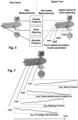
- a digital twin concept is illustrated in Figure 5 .
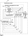
- FIG 6 shows a basic functional block diagram of an exemplary microprocessor system of a valve positioner, such as the microprocessor system 21 of a valve positioner illustrated in the examples of Figures 3 and 4 .
- the microprocessor system 21 is configured to store and run an embedded valve controller software module 210 and an embedded tracking digital twin software module 211.
- the embedded valve controller software module 210 may be, for example, similar to the embedded valve controller software module 210 described above with reference examples of Figures 3 and 4 .
- the embedded valve controller receives a setpoint position and the measured valve position and outputs a control signal to control the pneumatic actuator pressure of the pneumatic valve actuator and thereby the valve position of the control valve.
- the embedded valve controller software module 210 receives a set point h sp for valve position, a measured valve position (valve opening) h meas , and a measured actuator pressure p1 meas (optionally the further measured actuator pressure p2 meas . , particularly in the case the actuator 3 is a dual-acting actuator). Further, the embedded valve controller module 210 may receive the measured supply pressure sp meas . Based on the setpoint and measurements, the embedded valve controller module 210 controls the value of the electrical control signal 26 to achieve a desired control action in the physical valve assembly in accordance with a control algorithm or method employed in a specific application.
- the embedded tracking digital twin is configured to receive same controls and control actions as those provided by the embedded valve controller to a physical pneumatic actuator and/or a physical control valve, and in response to the controls and control actions, to generate at least one simulated measurement result (representing a simulated result of a control action) corresponding to at least one real physical measurement result measured from the physical pneumatic actuator and/or the physical control valve.
- the embedded tracking digital twin module 211 receives a control signal representing a real control of the at least part of the physical valve assembly, and one or more real measurements relating to the result of the real control in the at least part of the physical valve assembly.
- a control signal may include the electrical control signal 26, and/or one or more the real measurements.
- the real measurements relating to the result of the real control in the at least part of the physical valve assembly may include one or more of the measured valve position (valve opening) h meas , the measured actuator pressure p1 meas (optionally also the further measured actuator pressure p2 meas ), and the measured supply pressure sp meas , a measured control pressure (e.g. a pilot pressure) from the prestage, a measured control position of a pneumatic output stage (e.g. spool position) and/or any other real measurements x sim that may be useful (e.g. temperature or a process pressure).
- a measured control pressure e.g. a pilot pressure
- a measured control position of a pneumatic output stage e.g. spool position
- any other real measurements x sim that may be useful (e.g. temperature or a process pressure).
- a real control inputted to the simulation may be the measured actuator pressure p1 meas (optionally also the further measured actuator pressure p2 meas ), as illustrated by a broken line in Figure 6 , and the simulated result of the control may be a simulated valve position h sim .
- a real control inputted to the simulation may be the measured pilot pressure and the simulated result of the control may be the simulated actuator pressure p1 meas (optionally also a further simulated actuator pressure p2 sim ),
- the simulated measurements may be generated by a simulation block 212 of the embedded tracking digital twin that incorporates a simulation model or simulation models of at least part of a physical valve assembly, such as a simulation model of a physical valve 1, a pneumatic prestage, a pneumatic output stage, a supply pressure inlet and/or a pneumatic actuator 3,.
- the simulation model 212 comprises a plurality of simulation model parameters which include at least one fault-related simulation model parameter.
- a fault-related simulation model parameter relates to or is representative of a specific physical fault in the at least one physical part of the valve assembly.
- there are a plurality of fault-related simulation model parameters which relate to a plurality of different specific physical faults in physical part or parts of the valve assembly.
- the at least one fault-related simulation model parameter includes a fault-related simulation model parameter related to one of following specific physical dimensions: cross-sectional size of a pneumatic air supply, a cross-sectional size of a pilot pressure inlet, and a cross-sectional size of an actuator pressure leakage hole.
- the at least one fault-related simulation model parameter may include a further fault-related simulation model parameter that represents a further specific physical characteristic of the at least one physical part of the valve assembly, such a physical dimension or a friction, and the value of the specific physical characteristic is related to a specific physical fault.
- the at least one fault-related simulation model parameter includes one or more further fault-related simulation model parameters related to one or more of following specific physical characteristics: a valve friction, a bearing friction, a backlash, fatigue, erosion, wear.
- the embedded tracking digital twin tracks an error or difference between the at least one simulated measurement result representing a simulated result of a control action (such as the simulated measured valve position and/or the simulated measured pneumatic actuator pressure), and the at least one corresponding real physical measurement result (such as the measured valve position and/or the measured pneumatic actuator pressure), and adjusts a value of the at least one fault-related simulation model parameter of the embedded tracking digital twin in a sense that the error or difference is decreased, in real-time during operation of the valve assembly.
- a control action such as the simulated measured valve position and/or the simulated measured pneumatic actuator pressure
- the at least one corresponding real physical measurement result such as the measured valve position and/or the measured pneumatic actuator pressure
- the embedded tracking digital twin module 211 may be provided with a tracking and model parameter update block 213 that may receive one or more simulated measurement results (representing a simulated result of the real control), such as the simulated valve position h sim , the simulated actuator pressure p1 sim (optionally also the further measured actuator pressure p2 sim ), the simulated supply pressure sp meas , the simulated control pressure (e.g. a pilot pressure) from the prestage, the simulated control position of a pneumatic output stage (e.g. spool position) and/or any other simulated measurements xsim that may be useful (e.g. a valve temperature or a process pressure), from the simulation block 212.
- simulated measurement results depict a simulated result of the real control
- the simulated valve position h sim the simulated actuator pressure p1 sim (optionally also the further measured actuator pressure p2 sim )
- the simulated supply pressure sp meas the simulated control pressure (e.g.
- the tracking and model parameter update block 213 may the measured valve position (valve opening) h meas , and the measured actuator pressure p meas (optionally also the further measured actuator pressure p meas ).
- the tracking and model parameter update block 213 may compare the simulated and measured values to track an error or difference between the results of simulated operation of the digital twin and the real operation of the physical asset.
- the simulation model is built in a manner that includes one or more fault related simulation model parameters
- the tracking and model parameter update block 213 is able to consider or test whether the error or difference in the simulated and real operation is due to one or more of these fault-related simulation parameters.
- the model parameters in the simulation model in the simulation block 212 may be updated accordingly.
- the change in the value of the fault-related simulation model parameter may be indicative of existence or development of the specific physical fault. Therefore, existence of the specific physical fault and/or predict the development of the specific physical fault in the valve assembly can be detected.
- reliable on-line predictions about valve assembly faults can be provided.
- the embedded tracking digital twin 211 may store history and/or trend of values of the fault-related simulation model parameters in a memory of the microprocessor system 21 in real time or at predetermined longer intervals, such as once an hour, once a day, once a week, etc.
- the history and/trend data may be analysed in the microprocessor system 21, preferably in the embedded tracking digital twin.
- the microprocessor system, preferably the embedded tracking digital twin 211. may store and/or generate fault alarms and reports on faults in the valve assembly based on values of the fault-related simulation model parameters in a memory of the microprocessor system 21.
- the microprocessor system preferably the embedded tracking digital twin 211, may be configured to detect and identify the specific physical fault in the at least one physical part of the valve assembly when the adjusted value of the at least one fault-related simulation model parameter reaches a predetermined threshold value or a predetermined deviation.
- the microprocessor system preferably the embedded tracking digital twin 211, be may configured to predict a future trend of the adjusted value of the at least one fault-related simulation model parameter over the time, and to predict a remaining operation time until the adjusted value of the at least one fault-related simulation model parameter reaches a given limit value or a given deviation limit.
- At least part of the fault detection and identification, fault alarms, fault reporting, the fault prediction, and other diagnosis or prognosis routines may be performed by a remote computing component in a process control system or a maintenance monitoring system, such as a process computer or a maintenance monitoring computer, based on the values of the fault-related simulation model parameters.
- execution of at least part of the fault detection and identification, fault alarms, fault reporting, the fault prediction, and other diagnosis or prognosis routines may be distributed among the microprocessor system of the valve positioner and a remote a remote computing component in a process control system or a maintenance monitoring system.
- Figure 7 shows illustrative trends of physical values of fault-related simulation model parameters mp1, mp2, mp3, and mp4.
- the physical values of parameters mp1 and mp3 increase with time from the initial value.
- Examples of fault-related physical simulation model parameters whose increasing value may indicate or predict a specific physical fault include a valve friction and a bearing friction.
- An increasing valve friction may indicate a sticky valve and wearing of a valve seat.
- a change in the bearing friction may indicate damaged bearings in the valve assembly.
- the physical values of parameters mp2 and mp4 decrease with time from the initial value.
- Fault-related physical simulation model parameters whose decreasing value indicate or predict a specific physical fault include a cross-sectional area of an air supply and a pilot pressure inlet diameter of a pneumatic pre-stage of a valve positioner. They may indicate a gradual blocking of the air supply or the pilot pressure inlet due to dirt or some other reason.
- the positioner or a remote device analyzing the fault-related physical simulation model parameters can tell and identify the fault component or part, necessary service actions can be made immediately or scheduled to be made at an appropriate time by the maintenance personnel without need to analyse various reports.
- the necessary service actions may be to clean the air supply inlet or pilot pressure inlet, or replacement of bearings or a valve closure/seat.
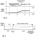
- the embedded tracking digital twin 211 may track an error or difference between the simulated pneumatic actuator pressure p sim (dashed line) and the measured pneumatic actuator pressure p meas (solid line).
- the simulated actuator pressure p sim follows quite accurately the measured pneumatic actuator pressure p meas , i.e. the trend lines substantially overlap.
- the tracking and model parameter update block 213 observes the simulated and measured values are substantially equal, i.e. there is no error, difference or deviation and no need to adjust any of the simulation model parameters.
- a single fault-related parameter, a leakage hole diameter is shown as one of a plurality of simulation model parameters that can utilized in the simulation model.
- the leakage hole diameter may relate to an air leakage in the pneumatic actuator 3, for example due to a hole in an actuator membrane and/or a leakage over an actuator piston, etc.
- the leakage hole diameter represents a cross-sectional size of a single "virtual" hole for the total air leakage that may be a combination of multiple leakages in the actuator 3.
- the diameter of the "virtual" leakage hole will be substantially equal to that of the real hole in the actuator membrane.
- tracking and model parameter update block 213 does not adjust any of the simulation model parameters, and also the leakage hole diameter is substantially unchanged during the time period t1-t2.
- the simulated actuator pressure p sim and the measured pneumatic actuator pressure p meas begin to diverge, such as shortly after time instant t2 in Figure 8 .
- the tracking and model parameter update block 213 detects the divergence (error, difference, deviation) and begins in real time to determine an updated value for one or more fault-related simulation model parameters of the embedded tracking digital twin in a sense that the error or difference is decreased.
- the tracking and model parameter update block 213 gradually increases the diameter of the leakage hole in the simulation model so that the simulated pneumatic actuator pressure p sim and the measured pneumatic actuator pressure p meas converge and finally overlap the time instant t3.
- the situation is stabilized and no further updating of simulation parameters will be needed during the time period t3-t4.
- the increased physical value of the fault-related parameter "Leakage hole diameter" directly indicates a leakage fault in the pneumatic actuator 3.
- the specific fault-related parameter also gives clear maintenance-relevant information, a physical diameter of the leakage hole. This information or measure can be utilized to determine how severe the fault is, e.g.
- the periods t1-t2, t2-t3, and t3-t4 can be very long periods of time, such as hours, days, weeks, months or years, in relation to the real time update of parameters that may be multiple times per second, for example.
- the microprocessor system 21, preferably the embedded tracking digital twin 211 may, based on the past behavior of the fault or the parameter, interpolate the future trend of a fault-related simulation model parameter mathematically. It should be appreciated that, depending on the specific fault in question, the time period past-to-present and the remaining useful lifetime can be very long periods of time, because the value of the fault-related simulation model parameter (such as friction of a valve) may change very slowly over the time until a limit is reached.
- the fault-related simulation model parameter such as friction of a valve
Landscapes
- Engineering & Computer Science (AREA)
- General Engineering & Computer Science (AREA)
- Physics & Mathematics (AREA)
- Mechanical Engineering (AREA)
- General Physics & Mathematics (AREA)
- Automation & Control Theory (AREA)
- Fluid Mechanics (AREA)
- Artificial Intelligence (AREA)
- Health & Medical Sciences (AREA)
- Computer Vision & Pattern Recognition (AREA)
- Evolutionary Computation (AREA)
- Medical Informatics (AREA)
- Software Systems (AREA)
- Power Engineering (AREA)
- Indication Of The Valve Opening Or Closing Status (AREA)
- Testing And Monitoring For Control Systems (AREA)
Description
- The invention relates to control valves, and particularly to diagnostics of control valves using valve positioners.
- Actuators are frequently used as mechanisms to introduce motion or control motion. It is operated by a source of energy, typically electric current, hydraulic fluid pressure, or pneumatic fluid pressure, and converts that energy into motion of a target mechanism, such as into movement of a closure element of a control valve.
- A control valve is generally used for a continuous control of a liquid or gas flow in different pipelines and processes. In a processing industry, such as oil and gas, mining, pulp and paper and chemical industries, different kinds of control valves installed in a plant's pipe system control material flows in the process. A material flow may contain any fluid material, such as fluids, liquors, liquids, gases and steam. The operation of a control valve involves positioning its movable or closing part (e.g. the plug, ball or disc) relative to the stationary seat of the valve. The control valve is usually connected with an actuator whose purpose is to accurately locate the closing element of the valve in a position dictated by a control signal. The actuator moves the closing element of the valve to a desired position between fully open and fully closed positions. The actuator may be a pneumatic or a hydraulic cylinder-piston device, for example. The actuator, for its part, is usually controlled by a valve positioner, also called as a valve controller, for controlling the position of the closing element of the control valve and thus the material flow in the process according to a control signal from a process controller. A position sensor (such as a potentiometer) feeds a signal representing the actual valve position to the positioner. In this way the actuator can be positioned along its stroke in proportion to the control signal. Hence the positioner operates as a feedback controller.
- One of the newer devices that offer improved performance of control valves is so-called "smart" positioner or a digital valve controller. One example of a smart positioner is the Neles NDX valve controller sold by Metso Corporation. A smart positioner is a microprocessor-based electronic positioner with internal logic capability which derives benefit from digital programming to obtain improved positioning performance. An advantage of the smart positioner is that it may be programmed to use a position control algorithm to achieve better dynamic response. Further, the smart positioner may use 2-way communications protocols such Hart, Foundation Fieldbus etc. to communicate with a process control system. This type of communication can be used also to enter new control settings or configurations remotely after installing a smart positioner.
- In addition to the primary purpose of controlling automated valves in the process industry, digital valve controllers may have various additional features that are useful for plant operation. One of the most important additional features is valve diagnostics. The diagnostics needs are simple: plant managers want to know for how long the valve is expected to operate, and if it is going fail, we should tell what part needs service or replacement. So far, no digital valve controller on the market can provide this information. Instead, although digital valve controllers are able to provide various kind historical trends and diagnostics reports for subsequent analysis, experienced service experts are needed to analyse such diagnostics reports. Still, valve diagnostics data is difficult to interpret even for experts.
US5748469A relates to a method for detecting a fault and locating a faulted component in an automatically operated control valve assembly in a control loop. The method is based on use of a generic mathematical model defining the dynamics and statics of a control valve, as illustrated by equations (1)-(5). A required amount of measurement data, such as the control signal and the valve position data, are collected and stored during a test run or a series of test runs, or from a control valve assembly in operation. Thereafter, post-processing calculations are carried out to fit the mathematical model to the stored actual measurement data. The parameters of the resulting fitted mathematical model may be compared with reference parameters measured in laboratory, or with previous values of the same parameter measured over a time. If the value of the parameter changes sufficiently from the reference value or if there is a sufficient long-term change in the value of the parameter, the parameter may be identified as a parameter indicating a fault in some part of the control valve assembly. - An object of the present invention is to provide a method and an apparatus for implementing the method.
- The object of the invention is achieved by a valve positioner and a method recited in the independent claims. The preferred embodiments of the invention are disclosed in the dependent claims.
- An aspect of the invention is a valve positioner, wherein the valve positioner is configured to be installed in a valve assembly comprises comprising the valve positioner, a control valve, a pneumatic valve actuator, a pressure sensor adapted to measure a pneumatic actuator pressure and a position sensor adapted to measure a valve position of the control valve, and wherein the valve positioner is configured to control the valve position of the control valve, utilizing the pneumatic valve actuator, and the valve positioner comprises a microprocessor system configured to (A) control the valve positioner to affect said control of the valve position of the control valve, (B) receive a setpoint position, at least the measured valve position and at least one real physical measurement result and (C) to store and run an embedded valve control and diagnostics software, the software including (c1) an embedded valve controller configured to (i) receive the setpoint position and at least the measured valve position and (ii) cause the microprocessor system to control the valve positioner to affect said control of the valve position of the control valve, and (c2) an embedded tracking digital twin of at least one physical part of the valve assembly, wherein the embedded tracking digital twin comprises a plurality of simulation model parameters, the plurality of simulation model parameters including at least one fault-related simulation model parameter that relates to a specific physical fault in the at least one physical part of the valve assembly,
- wherein the at least one fault-related simulation model parameter includes a fault-related simulation model parameter related to one of following specific physical dimensions: cross-sectional size of a pneumatic air supply, a cross-sectional size of a pilot pressure inlet, and a cross-sectional size of an actuator pressure leakage hole,
- wherein the embedded tracking digital twin is configured to (i) receive a control signal representing a real control of the at least one part of the physical valve assembly caused by the embedded valve controller, (ii) provide at least one simulated measurement result representing a simulated result of a control action in real-time during operation of the valve assembly, (iii) track an error between the at least one simulated measurement result and the at least one corresponding real physical measurement result, and (iv) adjust a value of the at least one fault-related simulation model parameter of the embedded tracking digital twin in a sense that the error is decreased, in real-time during operation of the valve assembly, and
- wherein the specific physical fault in the at least one physical part of the valve assembly is detectable and identifiable based on the adjusted value of the at least one simulation model parameter.
- In an embodiment, the at least part of the valve assembly the embedded tracking digital twin of at least one physical part of the valve assembly comprises an embedded tracking digital twin of one or more of the control valve, the pneumatic valve actuator, a pneumatic pre-stage in the valve positioner, a supply pressure inlet, a pneumatic output stage in the valve positioner, and any combination thereof.
- In an embodiment, the microprocessor system is configured to receive a measured pneumatic actuator pressure and the embedded tracking digital twin is configured to (i) receive the control signal from the embedded valve controller, (ii) provide a simulated measured valve position and/or a simulated measured pneumatic actuator pressure in real-time during operation of the valve assembly, (iii) track an error between the simulated measured valve position and the measured valve position and/or an error between the simulated measured pneumatic actuator pressure and the measured pneumatic actuator pressure, and (iv) adjust a value of the at least one fault-related simulation model parameter of the embedded tracking digital twin in a sense that the error is decreased, in real-time during operation of the valve assembly.
- In an embodiment, the control signal representing the real control of the at least part of the physical valve assembly includes an electrical control signal to a prestage and/or one or more of the at least one real physical measurement result.
- In an embodiment, the at least one real physical measurement result that relates to the result of the real control in the at least part of the physical valve assembly may include one or more of: the measured valve position, the measured actuator pressure, a further measured actuator pressure, a measured supply pressure, a measured pilot pressure from a pneumatic prestage, a measured control position of a pneumatic output stage, a valve temperature, and a process pressure).
- In an embodiment, the valve assembly further comprises a pressure sensor adapted to measure a pneumatic supply pressure, and wherein the embedded tracking digital twin is configured to receive the measured pneumatic supply pressure and to utilize it in adjustment of the plurality of simulation model parameters.
- In an embodiment, the microprocessor system of the valve positioner and/or a remote computing entity is configured to detect and identify the specific physical fault in the at least one physical part of the valve assembly when the adjusted value of the at least one fault-related simulation model parameter reaches a predetermined threshold value or a predetermined deviation.
- In an embodiment, the microprocessor system of the valve positioner and/or a remote computing entity is configured to predict a future trend of the adjusted value of the at least one fault-related simulation model parameter over the time, and to predict a remaining operation time until the adjusted value of the at least one fault-related simulation model parameter reaches a given limit value or a given deviation limit.
- In an embodiment, the microprocessor system of the valve positioner and/or a remote computing entity is configured to predict a remaining useful lifetime of the at least one physical part of the valve assembly.
- In an embodiment, the plurality of simulation model parameters includes a plurality of fault-related simulation model parameters which relate to a plurality of different specific physical faults in the in the at least one physical part of the valve assembly.
- In an embodiment, the at least one fault-related simulation model parameter includes a further fault-related simulation model parameter that represents a further specific physical characteristic of the at least one physical part of the valve assembly, such as a physical dimension or a friction, and wherein the value of the specific physical characteristic is related to a specific physical fault.
- In an embodiment, the at least one fault-related simulation model parameter includes one or more further fault-related simulation model parameters related to one or more of following specific physical characteristics: a valve friction, a bearing friction, a backlash, fatigue, erosion, wear.
- Another aspect of the invention is a valve assembly comprising a control valve, a pneumatic valve actuator, a pressure sensor adapted to measure a pneumatic actuator pressure, a position sensor adapted to measure a valve position of the control valve, and a valve positioner according to any embodiment.
- A further aspect of the invention is a diagnostic method in a valve positioner of a valve assembly, comprising
- measuring a pneumatic actuator pressure of a pneumatic valve actuator of the valve assembly,
- measuring a valve position of a control valve of the valve assembly,
- running an embedded valve controller in real-time in a microprocessor system of the valve positioner causing by the embedded valve controller, the microprocessor system of the valve positioner to control the pneumatic actuator pressure of the pneumatic valve actuator and thereby the valve position of the control valve based on a setpoint position and the measured valve position in real-time during operation of the valve assembly,
- running an embedded tracking digital twin of at least one physical part of the valve assembly in the microprocessor system of the valve positioner, wherein the embedded tracking digital twin comprises a plurality of simulation model parameters, the plurality of simulation model parameters including at least one fault-related simulation model parameter that relates to a specific physical fault in the at least one physical part of the valve assembly, wherein the at least one fault-related simulation model parameter includes a fault-related simulation model parameter related to one of following specific physical dimensions cross-sectional size of a pneumatic air supply, a cross-sectional size of a pilot pressure inlet, and a cross-sectional size of an actuator pressure leakage hole,
- receiving, by the embedded tracking digital twin, a control signal representing a real control of the at least part of the physical valve assembly from the embedded valve controller and to provide at least one simulated measurement result representing a simulated result of a control in real-time during operation of the valve assembly,
- generating, by the embedded tracking digital twin, at least one simulated measurement result representing a simulated result of a control action in real-time during operation of the valve assembly,
- tracking, by the embedded tracking digital twin, an error between the at least one simulated measurement result and at least one corresponding real physical measurement result in real-time during operation of the valve assembly, and
- adjusting, by the embedded tracking digital twin, a value of the at least one fault-related simulation model parameter of the embedded tracking digital twin in a sense that the error is decreased, in real-time during operation of the valve assembly, wherein the specific physical fault in the at least one physical part of the valve assembly is identifiable based on the adjusted value of the at least one simulation model parameter.
- In the following the invention will be described in greater detail by means of preferred embodiments with reference to the attached drawings, in which
-
Figure 1 shows a schematic block diaphragm of an exemplary process automation system; -
Figure 2 illustrates an exemplary physical valve assembly wherein a pneumatic actuator operates a process valve under control of a valve positioner; -
Figure 3 illustrates a basic block diagram of an exemplary microcontroller-based smart valve positioner wherein valve diagnostics according to embodiments of the invention are applied; -
Figure 4 shows a schematic block diagram of an exemplary intelligent valve controller wherein valve diagnostics according to embodiments of the invention are applied; -
Figure 5 illustrates an example of a digital twin concept according to the invention; -
Figure 6 shows a basic functional block diagram of a microprocessor system of a valve positioner according to exemplary embodiments; -
Figure 7 shows illustrative trends of physical values of fault-related simulation model parameters; -
Figure 8 shows an example of updating a fault-related simulation model parameter in real time during operation; and -
Figure 9 illustrates an example of predicting a remaining useful lifetime. -
Figure 1 shows a schematic block diaphragm of an exemplary process automation system wherein the principles of the invention may be applied in a valve positioner. Thecontrol system block 5 generally represents any and all control room computer(s)/programs and process control computer(s)/programs as well as databases, which may be interconnected by afactory LAN 4, in the automation system. There are various architectures for a control system. For example, the control system may be a Direct Digital Control (DDC) system or Distributed Control System (DCS), both well known in the art. It should be appreciated that the type or architecture of the automation system is not relevant to the present invention. - In the example of
Figure 1 , a control valve assembly comprising aprocess valve 1 and apositioner 2 and anactuator 3 may be connected to a process to control the flow of a substance in aprocess pipeline 7.Figure 2 shows a side view an exemplary physical valve assembly and its components aprocess valve 1, apositioner 2 and anactuator 3. Material flows of a process or process pipeline may be controlled in a processing industry, such as oil and gas, mining, pulp and paper, and chemical industries. The material flow may contain any fluid material, such as fluids, liquors, liquids, gases and steam. Although only one controlled process valve assembly is shown inFigure 1 , an automation system may, however, include any number of field devices, such as control valve assemblies, often hundreds of them.Figure 2 illustrates a mechanical structure of an exemplary control valve assembly and its physical components: apneumatic actuator 3, acontrol valve 1, and avalve positioner 2. An example of acontrol valve 1 is Neles® Finetrol eccentric rotary plug valve from Metso Corporation. An example of avalve positioner 2 wherein embodiments of the invention may be applied is Neles® NDX valve controller manufactured by Metso Corporation. An example of anactuator 3 is Quadra-Powr® X series pneumatic actuator from Metso Corporation. However, it is to be understood that, beyond the novel valve diagnostics, the type and implementation of the control valve assembly is not relevant to the present invention. As used herein, the term "control valve" also includes an on/off type shutoff valve. - There are various alternative ways to arrange the interconnection between the control system and field devices, such as control valves, in a plant area. In
Figure 1 , the field/process bus 6 generally represents any such interconnection. Traditionally, field devices have been connected to the control system by two-wire twisted pair loops, each device being connected to the control system by a single twisted pair providing a 4 to 20 mA analog input signal. More recently, new solutions, such as Highway Addressable Remote Transducer (HART) protocol, that allow the transmission of digital data together with the conventional 4 to 20 mA analog signal in the twisted pair loop have been used in the control systems. The HART protocol is described in greater detail for example in the publication HART Field Communication Protocol: An Introduction for Users and Manufacturers, HART Communication Foundation, 1995. The HART protocol has also been developed into an industrial standard. Examples of other fieldbuses include Foundation Fieldbus and Profibus PA. However, it is to be understood that the type or implementation of the field/process bus 3 is not relevant to the present invention. The field/process bus 6 may be based on any one of the alternatives described above, or on any combination of the same, or on any other implementation. - A basic block diagram of an exemplary microcontroller-based smart valve positioner, such as
positioner 2, is illustrated inFigure 3 .Figure 4 shows a more detailed schematic block diagram of an exemplaryintelligent valve controller 2. Theexemplary positioner 2 may include amicrocontroller unit 21 having anelectrical control output 26, and apneumatic unit 23/25 that may take in theelectrical control signal 26 and convert it to a pneumatic actuator pressure p1 at an actuator port C1 that may be connected to a single-acting actuatorpressure supply line 33. In the example ofFigure 4 , thevalve positioner 2 is configured to control a double-actingpneumatic actuator 3, and therefore illustrated to have two actuator ports C1 and C2 connected to anactuator 3 over actuatorpressure supply lines Figure 3 . A further actuator pressure sensor P2 may be arranged to measure the pneumatic pressure p2 at the actuator port C2 and to provide a further measured actuator pressure p2meas signal, when a double-actingactuator 3 is operated. A supply pressure sensor PS may be arranged to measure the pneumatic supply pressure sp at the supply port SP and to provide a measured supply pressure spmeas signal. The pneumatic unit may comprise a pre-stage 23 and anoutput stage 25. Theprestage 23 may perform an electric-to-pressure (I/P) conversion of theelectrical control signal 26 into apneumatic control signal 24, a pilot pressure, which is sufficient to control theoutput stage 25. The supply port S of theoutput stage 25 may be connected to an external supply air pressure S. Theoutput stage 25 may amplify the small pneumatic pilot signal into a larger pneumatic actuator pressure outputs 33 and 34 at the actuator ports C1 and C2 to movediaphragm pistons 32 of theactuator 3. Aposition sensor 22 may be provided to measure the position of theactuator 3 or controlvalve 1, and provide a measured valve position (valve opening) hmeas signal to themicrocontroller system 21. For example, theposition sensor 22 may be arranged to measure the rotation of ashaft 31 of theactuator 3, which rotation represents the valve position or opening. Amicrocontroller system 21 may control the valve position according to a control algorithm run in themicrocontroller system 21. It should be appreciated that a specific control algorithm used is not relevant to the present invention. In theexemplary valve positioner 2 illustrated inFigure 3 , the control is performed by an embedded valvecontroller software module 210 which is stored and run in themicrocontroller system 21. To that end, the embeddedvalve controller module 210 may receive an input signal (a set point hsp), which may be received over a process/fieldbus 7, such as 4-20 mA pair and HART, connected to aconnector 27, as illustrated inFigure 4 . The embeddedvalve controller module 210 may further receive the measured valve position hmeas from theposition sensor 22, and one or more of the measured actuator pressure p1meas from an actuator pressure sensor P1 and the further measured actuator pressure p2meas from the further actuator pressure sensorP2. Further, the embeddedvalve controller module 210 may receive the measured supply pressure spmeas from supply pressure sensor PS. Based on the setpoint and measurements, the embeddedvalve controller module 210 may control the value of theelectrical control signal 26 to achieve a desired control action. Thepositioner 2 may further contain a Local User Interface (LUI) 20 connected to themicrocontroller 21. Themicrocontroller 21 may display any information on a display of thelocal user interface 20, and receive commands and parameters from a keypad or buttons of thelocal user interface 20. Thepositioner 2 may be powered from a 4-20 mA loop or fieldbus. It should be appreciated that the illustrated valve positioner is merely an example and the type or implementation of avalve positioner 2, beyond valve diagnostics, is not relevant to the present invention. - An aspect of the invention is to create a diagnostics or prognosis platform that is able indicate and identify which part of the valve assembly has failed or will fail next.
- According to an aspect of the invention, new fault diagnostics are provided by a utilizing an embedded tracking digital twin of at least one physical part of a valve assembly in a microprocessor system of the valve positioner. The embedded tracking digital twin comprises a plurality of simulation model parameters which include at least one fault-related simulation model parameter. A fault-related simulation model parameter relates to or is representative of a specific physical fault in the at least one physical part of the valve assembly. By running an embedded tracking digital twin (i.e. a tracking simulation model) of at least one physical part of a valve assembly in real-time inside a valve positioner, and by considering various faults in the virtual domain using fault-related simulation model parameters, reliable on-line fault detections, fault identifications, and even predictions about valve faults, can be made. Simulations, fault detections and fault predictions can be made inside a valve positioner or controller or in a remote computing entity or distributed between a valve positioner and one or more remote computing entity.
- Generally, a digital twin is a (digital) virtual model of a physical asset in the physical world. A simulation-based digital twin concept incorporates the physical asset (e.g. product or process), a simulation model (models) and connections that facilitate communications between the two. According to the invention, the digital twin includes a simulation model that has been developed to duplicate the current condition of the physical asset, by incorporating fault-related simulation model parameters into the simulation model.
- In the invention, the physical asset includes at least part of the valve assembly, such as one of a physical control valve, a physical pneumatic valve actuator, a physical pneumatic pre-stage in a valve positioner, a pneumatic output stage in a valve positioner, a supply pressure inlet, or any combination thereof. An example of a digital twin concept according to is illustrated in
Figure 5 . -
Figure 6 shows a basic functional block diagram of an exemplary microprocessor system of a valve positioner, such as themicroprocessor system 21 of a valve positioner illustrated in the examples ofFigures 3 and4 . Themicroprocessor system 21 is configured to store and run an embedded valvecontroller software module 210 and an embedded tracking digitaltwin software module 211. The embedded valvecontroller software module 210 may be, for example, similar to the embedded valvecontroller software module 210 described above with reference examples ofFigures 3 and4 . - The embedded valve controller receives a setpoint position and the measured valve position and outputs a control signal to control the pneumatic actuator pressure of the pneumatic valve actuator and thereby the valve position of the control valve. In exemplary embodiments illustrated in
Figure 6 , the embedded valvecontroller software module 210 receives a set point hsp for valve position, a measured valve position (valve opening) hmeas, and a measured actuator pressure p1meas (optionally the further measured actuator pressure p2meas. , particularly in the case theactuator 3 is a dual-acting actuator). Further, the embeddedvalve controller module 210 may receive the measured supply pressure spmeas. Based on the setpoint and measurements, the embeddedvalve controller module 210 controls the value of theelectrical control signal 26 to achieve a desired control action in the physical valve assembly in accordance with a control algorithm or method employed in a specific application. - The embedded tracking digital twin is configured to receive same controls and control actions as those provided by the embedded valve controller to a physical pneumatic actuator and/or a physical control valve, and in response to the controls and control actions, to generate at least one simulated measurement result (representing a simulated result of a control action) corresponding to at least one real physical measurement result measured from the physical pneumatic actuator and/or the physical control valve. In exemplary embodiments illustrated in
Figure 6 , the embedded trackingdigital twin module 211 receives a control signal representing a real control of the at least part of the physical valve assembly, and one or more real measurements relating to the result of the real control in the at least part of the physical valve assembly. Such a control signal may include theelectrical control signal 26, and/or one or more the real measurements. The real measurements relating to the result of the real control in the at least part of the physical valve assembly may include one or more of the measured valve position (valve opening) hmeas , the measured actuator pressure p1meas(optionally also the further measured actuator pressure p2meas), and the measured supply pressure spmeas, a measured control pressure (e.g. a pilot pressure) from the prestage, a measured control position of a pneumatic output stage (e.g. spool position) and/or any other real measurements xsim that may be useful (e.g. temperature or a process pressure). Based on the real control and the real measurements, the embedded trackingdigital twin module 211 generates one or more simulated measurement results (representing a simulated result of the real control), such as a simulated valve position hsim, a simulated actuator pressure p1sim (optionally also a further measured actuator pressure p2sim), a simulated supply pressure spmeas, a simulated control pressure (e.g. a pilot pressure) from the prestage a simulated control position of a pneumatic output stage (e.g. spool position) and/or any other simulated measurements xsim that may be useful (e.g. a valve temperature or a process pressure). For example, for a simulation model of a physical valve only, a real control inputted to the simulation may be the measured actuator pressure p1meas (optionally also the further measured actuator pressure p2meas), as illustrated by a broken line inFigure 6 , and the simulated result of the control may be a simulated valve position hsim., As another example, for a simulation model of a pneumatic output stage only, a real control inputted to the simulation may be the measured pilot pressure and the simulated result of the control may be the simulated actuator pressure p1meas (optionally also a further simulated actuator pressure p2sim), In the exemplary embodiments ofFigure 6 , the simulated measurements may be generated by asimulation block 212 of the embedded tracking digital twin that incorporates a simulation model or simulation models of at least part of a physical valve assembly, such as a simulation model of aphysical valve 1, a pneumatic prestage, a pneumatic output stage, a supply pressure inlet and/or apneumatic actuator 3,. - The
simulation model 212 comprises a plurality of simulation model parameters which include at least one fault-related simulation model parameter. A fault-related simulation model parameter relates to or is representative of a specific physical fault in the at least one physical part of the valve assembly. In embodiments, there are a plurality of fault-related simulation model parameters which relate to a plurality of different specific physical faults in physical part or parts of the valve assembly. The at least one fault-related simulation model parameter includes a fault-related simulation model parameter related to one of following specific physical dimensions: cross-sectional size of a pneumatic air supply, a cross-sectional size of a pilot pressure inlet, and a cross-sectional size of an actuator pressure leakage hole. - In embodiments, the at least one fault-related simulation model parameter may include a further fault-related simulation model parameter that represents a further specific physical characteristic of the at least one physical part of the valve assembly, such a physical dimension or a friction, and the value of the specific physical characteristic is related to a specific physical fault. In embodiments of the invention, the at least one fault-related simulation model parameter includes one or more further fault-related simulation model parameters related to one or more of following specific physical characteristics: a valve friction, a bearing friction, a backlash, fatigue, erosion, wear.
- In embodiments, the embedded tracking digital twin tracks an error or difference between the at least one simulated measurement result representing a simulated result of a control action (such as the simulated measured valve position and/or the simulated measured pneumatic actuator pressure), and the at least one corresponding real physical measurement result (such as the measured valve position and/or the measured pneumatic actuator pressure), and adjusts a value of the at least one fault-related simulation model parameter of the embedded tracking digital twin in a sense that the error or difference is decreased, in real-time during operation of the valve assembly. In exemplary embodiments illustrated in
Figure 6 , the embedded trackingdigital twin module 211 may be provided with a tracking and modelparameter update block 213 that may receive one or more simulated measurement results (representing a simulated result of the real control), such as the simulated valve position hsim, the simulated actuator pressure p1sim (optionally also the further measured actuator pressure p2sim), the simulated supply pressure spmeas, the simulated control pressure (e.g. a pilot pressure) from the prestage, the simulated control position of a pneumatic output stage (e.g. spool position) and/or any other simulated measurements xsim that may be useful (e.g. a valve temperature or a process pressure), from thesimulation block 212. The tracking and modelparameter update block 213 may the measured valve position (valve opening) hmeas, and the measured actuator pressure pmeas (optionally also the further measured actuator pressure pmeas). The tracking and modelparameter update block 213 may compare the simulated and measured values to track an error or difference between the results of simulated operation of the digital twin and the real operation of the physical asset. As the simulation model is built in a manner that includes one or more fault related simulation model parameters, the tracking and modelparameter update block 213 is able to consider or test whether the error or difference in the simulated and real operation is due to one or more of these fault-related simulation parameters. In the case it is determined that the error or difference can be decreased by adjusting or updating value or values of one or more of the fault-related simulation model parameters, the model parameters in the simulation model in thesimulation block 212 may be updated accordingly. As each fault-related simulation model parameter may be related to or representative of a specific physical fault in the physical valve assembly, the change in the value of the fault-related simulation model parameter may be indicative of existence or development of the specific physical fault. Therefore, existence of the specific physical fault and/or predict the development of the specific physical fault in the valve assembly can be detected. Thus, by considering various faults in the virtual domain, reliable on-line predictions about valve assembly faults can be provided. In embodiments, the embedded trackingdigital twin 211 may store history and/or trend of values of the fault-related simulation model parameters in a memory of themicroprocessor system 21 in real time or at predetermined longer intervals, such as once an hour, once a day, once a week, etc. In embodiments, the history and/trend data may be analysed in themicroprocessor system 21, preferably in the embedded tracking digital twin. The microprocessor system, preferably the embedded trackingdigital twin 211. may store and/or generate fault alarms and reports on faults in the valve assembly based on values of the fault-related simulation model parameters in a memory of themicroprocessor system 21. In embodiments, the microprocessor system, preferably the embedded trackingdigital twin 211, may be configured to detect and identify the specific physical fault in the at least one physical part of the valve assembly when the adjusted value of the at least one fault-related simulation model parameter reaches a predetermined threshold value or a predetermined deviation. In embodiments, the microprocessor system, preferably the embedded trackingdigital twin 211, be may configured to predict a future trend of the adjusted value of the at least one fault-related simulation model parameter over the time, and to predict a remaining operation time until the adjusted value of the at least one fault-related simulation model parameter reaches a given limit value or a given deviation limit. In embodiments, at least part of the fault detection and identification, fault alarms, fault reporting, the fault prediction, and other diagnosis or prognosis routines may be performed by a remote computing component in a process control system or a maintenance monitoring system, such as a process computer or a maintenance monitoring computer, based on the values of the fault-related simulation model parameters. In embodiments, execution of at least part of the fault detection and identification, fault alarms, fault reporting, the fault prediction, and other diagnosis or prognosis routines may be distributed among the microprocessor system of the valve positioner and a remote a remote computing component in a process control system or a maintenance monitoring system. -
Figure 7 shows illustrative trends of physical values of fault-related simulation model parameters mp1, mp2, mp3, and mp4. In the example, the physical values of parameters mp1 and mp3 increase with time from the initial value. Examples of fault-related physical simulation model parameters whose increasing value may indicate or predict a specific physical fault include a valve friction and a bearing friction. An increasing valve friction may indicate a sticky valve and wearing of a valve seat. A change in the bearing friction may indicate damaged bearings in the valve assembly. In the example, the physical values of parameters mp2 and mp4 decrease with time from the initial value. Fault-related physical simulation model parameters whose decreasing value indicate or predict a specific physical fault include a cross-sectional area of an air supply and a pilot pressure inlet diameter of a pneumatic pre-stage of a valve positioner. They may indicate a gradual blocking of the air supply or the pilot pressure inlet due to dirt or some other reason. As the fault can be readily detected or predicted by means of the digital twin concept of the invention, , and the positioner or a remote device analyzing the fault-related physical simulation model parameters can tell and identify the fault component or part, necessary service actions can be made immediately or scheduled to be made at an appropriate time by the maintenance personnel without need to analyse various reports. In the example, the necessary service actions may be to clean the air supply inlet or pilot pressure inlet, or replacement of bearings or a valve closure/seat. - Now exemplary operation of an embedded tracking
digital twin 211 is discussed by means of an example illustrated inFigure 8 . InFigure 8 , the embedded trackingdigital twin 211 may track an error or difference between the simulated pneumatic actuator pressure psim (dashed line) and the measured pneumatic actuator pressure pmeas (solid line). During normal operation of the valve assembly, such as within the time period t1-t2, the simulated actuator pressure psim follows quite accurately the measured pneumatic actuator pressure pmeas, i.e. the trend lines substantially overlap. The tracking and modelparameter update block 213 observes the simulated and measured values are substantially equal, i.e. there is no error, difference or deviation and no need to adjust any of the simulation model parameters. InFigure 8 a single fault-related parameter, a leakage hole diameter, is shown as one of a plurality of simulation model parameters that can utilized in the simulation model. The leakage hole diameter may relate to an air leakage in thepneumatic actuator 3, for example due to a hole in an actuator membrane and/or a leakage over an actuator piston, etc. The leakage hole diameter represents a cross-sectional size of a single "virtual" hole for the total air leakage that may be a combination of multiple leakages in theactuator 3. In the case the only fault is the hole in the actuator membrane, the diameter of the "virtual" leakage hole will be substantially equal to that of the real hole in the actuator membrane. In the example ofFigure 8 , tracking and modelparameter update block 213 does not adjust any of the simulation model parameters, and also the leakage hole diameter is substantially unchanged during the time period t1-t2. - However, during a fault in the valve assembly, the simulated actuator pressure psim and the measured pneumatic actuator pressure pmeas begin to diverge, such as shortly after time instant t2 in
Figure 8 . This due to that thesimulation model 212 of the physical valve assembly still simulates the unfaulty valve assembly and not the actual faulty valve assembly. The tracking and modelparameter update block 213 detects the divergence (error, difference, deviation) and begins in real time to determine an updated value for one or more fault-related simulation model parameters of the embedded tracking digital twin in a sense that the error or difference is decreased. In the example ofFigure 8 , during the timer period t2-t3, the tracking and modelparameter update block 213 gradually increases the diameter of the leakage hole in the simulation model so that the simulated pneumatic actuator pressure psim and the measured pneumatic actuator pressure pmeas converge and finally overlap the time instant t3. The situation is stabilized and no further updating of simulation parameters will be needed during the time period t3-t4. The increased physical value of the fault-related parameter "Leakage hole diameter" directly indicates a leakage fault in thepneumatic actuator 3. The specific fault-related parameter also gives clear maintenance-relevant information, a physical diameter of the leakage hole. This information or measure can be utilized to determine how severe the fault is, e.g. whether the fault requires immediate service, or to predict the remaining useful lifetime of theactuator 3 until the next maintenance action shall be scheduled. It should be appreciated that the periods t1-t2, t2-t3, and t3-t4 can be very long periods of time, such as hours, days, weeks, months or years, in relation to the real time update of parameters that may be multiple times per second, for example. -
Figure 9 illustrates an example of predicting a remaining useful lifetime. The past values of the fault-related simulation model parameter (the leakage hole diameter in this example) create a historian trend of the development of the fault. In embodiments, themicroprocessor system 21, preferably the embedded trackingdigital twin 211 may, based on the past behavior of the fault or the parameter, simulate the future trend of the fault-related simulation model parameter over time, e.g. until the value of the fault-related simulation model parameter reaches a given limit value or a given deviation limit, or until the detected and identified specific fault reaches a given limit level. In embodiments, themicroprocessor system 21, preferably the embedded trackingdigital twin 211 may, based on the past behavior of the fault or the parameter, interpolate the future trend of a fault-related simulation model parameter mathematically. It should be appreciated that, depending on the specific fault in question, the time period past-to-present and the remaining useful lifetime can be very long periods of time, because the value of the fault-related simulation model parameter (such as friction of a valve) may change very slowly over the time until a limit is reached. - It will be obvious to a person skilled in the art that, as the technology advances, the inventive concept can be implemented in various ways. The invention and its embodiments are not limited to the examples described above but may vary as long as not departing from the scope of the present invention as defined by the appended claims.
Claims (14)
- A valve positioner (2), wherein the valve positioner is configured to be installed in a valve assembly comprising the valve positioner (2), a control valve (1), a pneumatic valve actuator (3), a pressure sensor (P1, P2) adapted to measure a pneumatic actuator pressure (p1meas, p2meas) and a position sensor (22) adapted to measure a valve position (hmeas) of the control valve, and wherein the valve positioner (2) is configured to control the valve position of the control valve (1), utilizing the pneumatic valve actuator (3), and the valve positioner (2) comprises a microprocessor system (21) configured to (A) control the valve positioner (2) to affect said control of the valve position of the control valve (1), (B) receive a setpoint position (hsp), at least the measured valve position (hmeas) and at least one real physical measurement result, and (C) store and run an embedded valve control and diagnostics software, the software including(c1) an embedded valve controller (210) configured to(i) receive the setpoint position (hsp) and at least the measured valve position (hmeas), and(ii) cause the microprocessor system (21) to control the valve positioner (2) to affect said control of the valve position of the control valve (1), and(c2) an embedded tracking digital twin (211) of at least one physical part of the valve assembly, wherein the embedded tracking digital twin (211) comprises a plurality of simulation model parameters, the plurality of simulation model parameters including at least one fault-related simulation model parameter that relates to a specific physical fault in the at least one physical part of the valve assembly, wherein the at least one fault-related simulation model parameter includes a fault-related simulation model parameter related to one of following specific physical dimensions: a cross-sectional size of a pneumatic air supply, a cross-sectional size of a pilot pressure inlet, and a cross-sectional size of an actuator pressure leakage hole, andwherein the embedded tracking digital twin (211) is configured to(i) receive a control signal (26) representing a real control of the at least one part of the physical valve assembly caused by the embedded valve controller (210),(ii) provide at least one simulated measurement result (p1sim, p2sim, hsim) representing a simulated result of a control action in real-time during operation of the valve assembly,(iii) track an error between the at least one simulated measurement result and the at least one corresponding real physical measurement result, and(iv) adjust a value of the at least one fault-related simulation model parameter of the embedded tracking digital twin (211) in a sense that the error is decreased, in real-time during operation of the valve assembly, andwherein the specific physical fault in the at least one physical part of the valve assembly is detectable and identifiable based on the adjusted value of the at least one simulation model parameter.
- A valve positioner according to claim 1, wherein the embedded tracking digital twin (211) of at least one physical part of the valve assembly comprises an embedded tracking digital twin of one or more of the control valve (1), the pneumatic valve actuator (3), a pneumatic pre-stage (23) in the valve positioner (2), a supply pressure inlet (S), a pneumatic output stage (25) in the valve positioner (2), and any combination thereof.
- A valve positioner according to claim 1 or 2, whereinthe microprocessor system (21) is configured to receive a measured pneumatic actuator pressure (p1meas, p2meas), andthe embedded tracking digital twin (211) is configured to(i) receive the control signal (26) from the embedded valve controller (210),(ii) provide a simulated measured valve position (hsim) and/or a simulated measured pneumatic actuator pressure (p1sim, p2sim) in real-time during operation of the valve assembly,(iii) track an error between the simulated measured valve position (hsim) and the measured valve position (hmeas) and/or an error between the simulated measured pneumatic actuator pressure (p1sim, p2sim) and the measured pneumatic actuator pressure (p1meas, p2meas), and(iv) adjust a value of the at least one fault-related simulation model parameter of the embedded tracking digital twin (211) in a sense that the error is decreased, in real-time during operation of the valve assembly.
- A valve positioner according to any one of claims 1-3, wherein the control signal representing the real control of the at least part of the physical valve assembly includes an electrical control signal (26) to a prestage and/or one or more of the at least one real physical measurement result.
- A valve positioner according to any one of claims 1-4, wherein the at least one real physical measurement result that relates to the result of the real control in the at least part of the physical valve assembly, may include one or more of: the measured valve position (hmeas), the measured actuator pressure (p1meas), a further measured actuator pressure (p2meas), a measured supply pressure (spmeas), a measured pilot pressure from a pneumatic prestage (23), a measured control position of a pneumatic output stage (26), a temperature, and a process pressure.
- A valve positioner according to any one of claims 1-5, wherein the valve assembly further comprises a pressure sensor (Ps) adapted to measure a pneumatic supply pressure (spmeas), and wherein the embedded tracking digital twin (211) is configured to receive the measured pneumatic supply pressure (spmeas) and to utilize it in adjustment of the plurality of simulation model parameters.
- A valve positioner according to any one of claims 1-6, wherein the microprocessor system (21) of the valve positioner (2) and/or a remote computing entity is configured to detect and identify the specific physical fault in the at least one physical part of the valve assembly when the adjusted value of the at least one fault-related simulation model parameter reaches a predetermined threshold value or a predetermined deviation.
- A valve positioner according to any one of claims 1-7, wherein the microprocessor system (21) of the valve positioner (2) and/or a remote computing entity is configured to predict a future trend of the adjusted value of the at least one fault-related simulation model parameter over the time, and to predict a remaining operation time until the adjusted value of the at least one fault-related simulation model parameter reaches a given limit value or a given deviation limit.
- A valve positioner according to any one of claims 1-8, wherein the microprocessor system (21) of the valve positioner (2) and/or a remote computing entity is configured to predict a remaining useful lifetime of the at least one physical part of the valve assembly.
- A valve positioner according to any one of claims 1-9, wherein the plurality of simulation model parameters includes a plurality of fault-related simulation model parameters which relate to a plurality of different specific physical faults in the in the at least one physical part of the valve assembly.
- A valve positioner according to any one of claims 1-10, wherein the at least one fault-related simulation model parameter includes a further fault-related simulation model parameter that represents a further specific physical characteristic of the at least one physical part of the valve assembly, such as a physical dimension or a friction, and wherein the value of the specific physical characteristic is related to a specific physical fault.
- A valve positioner according to any one of claims 1-11, wherein the at least one fault-related simulation model parameter includes one or more further fault-related simulation model parameters related to one or more of following specific physical characteristics: a valve friction, a bearing friction, a backlash, fatigue, erosion, wear.
- A valve assembly comprising a control valve (1), a pneumatic valve actuator (3), a pressure sensor (P1, P2) adapted to measure a pneumatic actuator pressure, a position sensor (22) adapted to measure a valve position of the control valve (1), and a valve positioner (2) as claimed in any one of claims 1-12.
- A diagnostic method in a valve positioner of a valve assembly, comprisingmeasuring a pneumatic actuator pressure (p1meas, p2meas) of a pneumatic valve actuator (3) of the valve assembly,measuring a valve position (hmeas) of a control valve (1) of the valve assembly,running an embedded valve controller (210) in real-time in a microprocessor system (21) of the valve positioner (2),causing , by the embedded valve controller (210), the microprocessor system (21) of the valve positioner (2) to control the pneumatic actuator pressure of the pneumatic valve actuator (3) and thereby the valve position (h) of the control valve (1) based on a setpoint position and the measured valve position (hmeas) in real-time during operation of the valve assembly,running an embedded tracking digital twin (211) of at least one physical part of the valve assembly in the microprocessor system (21) of the valve positioner (2), wherein the embedded tracking digital twin (211) comprises a plurality of simulation model parameters, the plurality of simulation model parameters including at least one fault-related simulation model parameter that relates to a specific physical fault in the at least one physical part of the valve assembly, wherein the at least one fault-related simulation model parameter includes a fault-related simulation model parameter related to one of following specific physical dimensions cross-sectional size of a pneumatic air supply, a cross-sectional size of a pilot pressure inlet, and a cross-sectional size of an actuator pressure leakage hole,receiving, by the embedded tracking digital twin (211), a control signal (26) representing a real control of the at least part of the physical valve assembly from the embedded valve controller (210) and to provide at least one simulated measurement result representing a simulated result of a control in real-time during operation of the valve assembly,generating, by the embedded tracking digital twin (211), at least one simulated measurement result representing a simulated result of a control action in real-time during operation of the valve assembly,tracking, by the embedded tracking digital twin (211), an error between the at least one simulated measurement result and at least one corresponding real physical measurement result in real-time during operation of the valve assembly, andadjusting, by the embedded tracking digital twin (211), a value of the at least one fault-related simulation model parameter of the embedded tracking digital twin in a sense that the error is decreased, in real-time during operation of the valve assembly, wherein the specific physical fault in the at least one physical part of the valve assembly is identifiable based on the adjusted value of the at least one simulation model parameter.
Applications Claiming Priority (2)
| Application Number | Priority Date | Filing Date | Title |
|---|---|---|---|
| FI20185733A FI128783B (en) | 2018-09-03 | 2018-09-03 | Valve positioner and diagnostic method |
| PCT/FI2019/050624 WO2020049214A1 (en) | 2018-09-03 | 2019-09-03 | Valve positioner and diagnostic method |
Publications (3)
| Publication Number | Publication Date |
|---|---|
| EP3847510A1 EP3847510A1 (en) | 2021-07-14 |
| EP3847510A4 EP3847510A4 (en) | 2021-11-03 |
| EP3847510B1 true EP3847510B1 (en) | 2025-04-16 |
Family
ID=69723008
Family Applications (1)
| Application Number | Title | Priority Date | Filing Date |
|---|---|---|---|
| EP19858562.2A Active EP3847510B1 (en) | 2018-09-03 | 2019-09-03 | Valve positioner and diagnostic method |
Country Status (5)
| Country | Link |
|---|---|
| US (1) | US12000503B2 (en) |
| EP (1) | EP3847510B1 (en) |
| CN (1) | CN112673321B (en) |
| FI (1) | FI128783B (en) |
| WO (1) | WO2020049214A1 (en) |
Families Citing this family (28)
| Publication number | Priority date | Publication date | Assignee | Title |
|---|---|---|---|---|
| US12019963B2 (en) * | 2018-02-07 | 2024-06-25 | Incucomm, Inc. | Operations and maintenance systems and methods employing sensor-less digital twins |
| US20210240179A1 (en) * | 2020-01-31 | 2021-08-05 | Saudi Arabian Oil Company | Automated maintenance method and system for plant assets |
| DE102020118556A1 (en) * | 2020-07-14 | 2022-03-10 | Samson Aktiengesellschaft | Valve positioner, process plant with valve positioner, diagnostic procedures and use of a valve positioner |
| CN111911483B (en) * | 2020-07-16 | 2021-10-01 | 山东大学 | Fusion fault diagnosis and prediction method of hydraulic system based on digital twin |
| DE102020119379A1 (en) * | 2020-07-22 | 2022-01-27 | Samson Aktiengesellschaft | Positioner self-assessment for digital twin |
| EP3945378A1 (en) * | 2020-07-27 | 2022-02-02 | Siemens Aktiengesellschaft | Digital twin based process management in an internet-of-things network |
| CN111967189B (en) * | 2020-08-24 | 2021-04-27 | 中国石油大学(华东) | Fault diagnosis method and system for offshore oil underwater production system driven by digital twin |
| DE102020124541A1 (en) | 2020-09-21 | 2022-03-24 | Woco Industrietechnik Gmbh | Control valve position detection |
| DE102020213974A1 (en) | 2020-11-06 | 2022-05-12 | Festo Se & Co. Kg | Valve drive device, method for operating a valve drive device and process device |
| CN114593269B (en) * | 2020-12-03 | 2023-07-25 | 矻颀投资股份有限公司 | A valve with failure self-prediction function |
| CN113343482B (en) * | 2021-06-28 | 2024-05-31 | 中国人民解放军陆军装甲兵学院 | A vehicle powertrain health management method based on digital twins |
| CN113656985B (en) * | 2021-09-01 | 2024-03-15 | 上海仁童电子科技有限公司 | Modeling methods, fault diagnosis methods and devices for valve components in braking systems |
| EP4152112B1 (en) * | 2021-09-16 | 2025-11-19 | Siemens Healthineers AG | Method for operating a medical device and medical device |
| DE102021210327A1 (en) * | 2021-09-17 | 2023-03-23 | Robert Bosch Gesellschaft mit beschränkter Haftung | CONTINUOUS MONITORING AND/OR DELIVERY OF SOFTWARE |
| CN114707438A (en) * | 2022-03-29 | 2022-07-05 | 杭州老板电器股份有限公司 | Evaluation method, evaluation device, equipment and storage medium for surface pressure of check valves |
| CN115163910B (en) * | 2022-06-30 | 2024-09-20 | 杭州电子科技大学 | A method for dynamically optimizing and adjusting control parameters of intelligent valve positioner |
| WO2024015387A1 (en) * | 2022-07-12 | 2024-01-18 | Cummins Inc. | Systems and methods for prognostics for health prediction of air handling valve-actuator with position sensing |
| CN115373278B (en) * | 2022-10-25 | 2023-01-06 | 北京安帝科技有限公司 | Industrial control service abnormity prediction response system and method based on digital twin drive |
| DE102023203169A1 (en) * | 2023-04-05 | 2024-10-10 | Robert Bosch Gesellschaft mit beschränkter Haftung | Method for operating a system with a digital twin |
| CN116520805B (en) * | 2023-05-10 | 2025-11-14 | 重庆长安汽车股份有限公司 | Construction system and methods for digital twin platform, and AEB testing equipment and methods |
| CN116624643A (en) * | 2023-05-22 | 2023-08-22 | 速特自动化(湖南)有限公司 | An intelligent valve positioner and its valve position deviation adjustment method |
| CN117108600B (en) * | 2023-10-24 | 2024-02-06 | 江苏二马液压元件有限公司 | A pressure control method and system for a pressure control valve in a hydraulic system |
| CN117450137B (en) * | 2023-10-30 | 2026-04-14 | 合肥工业大学 | A Digital Twin Modeling and Fault Prediction Method for Large Hydraulic Cylinders |
| CN117709185B (en) * | 2023-11-08 | 2024-07-30 | 浙江大学 | Digital twin architecture design method for process industry |
| CN118311951B (en) * | 2024-04-16 | 2026-03-06 | 北京航空航天大学 | A Fault Diagnosis Method for Electromechanical Servo Systems Based on Simulation-Driven and Subdomain Adaptation |
| CN119645151B (en) * | 2024-12-05 | 2025-12-02 | 中国气象局人工影响天气中心 | Environmental data processing methods, equipment, and storage media based on digital twins |
| CN119467855B (en) * | 2025-01-09 | 2025-05-23 | 温州职业技术学院 | Reverse flow valve based on early warning control of digital twin technology |
| CN121070071B (en) * | 2025-11-05 | 2026-02-03 | 展旭德自控阀门有限公司 | Hydraulic control system and method based on gas-liquid linkage |
Family Cites Families (13)
| Publication number | Priority date | Publication date | Assignee | Title |
|---|---|---|---|---|
| US5549137A (en) | 1993-08-25 | 1996-08-27 | Rosemount Inc. | Valve positioner with pressure feedback, dynamic correction and diagnostics |
| DE69515096T2 (en) * | 1994-10-18 | 2000-07-20 | Neles Controls Oy, Helsinki | Method and device for determining a fault in a control valve arrangement in a control loop |
| US5992229A (en) * | 1996-02-05 | 1999-11-30 | Neles-Jamesbury Oy | Method and equipment for determining the performance of control valve |
| FI104129B1 (en) * | 1996-06-11 | 1999-11-15 | Neles Jamesbury Oy | Procedure for monitoring the condition of control valve |
| US6678584B2 (en) * | 2002-05-03 | 2004-01-13 | Fisher Controls International Llc | Method and apparatus for performing diagnostics in a control loop of a control valve |
| JP4064159B2 (en) | 2002-06-06 | 2008-03-19 | 本田技研工業株式会社 | Plant control equipment |
| US7173539B2 (en) | 2004-09-30 | 2007-02-06 | Florida Power And Light Company | Condition assessment system and method |
| ATE511128T1 (en) | 2005-04-04 | 2011-06-15 | Fisher Rosemount Systems Inc | STATISTICAL PROCESSING METHODS FOR DETECTING ANORMAL SITUATIONS |
| FI125797B (en) | 2009-01-09 | 2016-02-29 | Metso Flow Control Oy | Method and device for valve maintenance inspection |
| EP2588924A4 (en) | 2010-06-30 | 2014-03-26 | Metso Automation Oy | Tracking simulation method |
| US20170286572A1 (en) | 2016-03-31 | 2017-10-05 | General Electric Company | Digital twin of twinned physical system |
| KR101885429B1 (en) * | 2016-08-30 | 2018-09-10 | 한국수력원자력 주식회사 | An apparatus for diagnosing a pneumatic control valve using positioner model and method thereof |
| CN109891352B (en) | 2016-09-21 | 2023-04-28 | 维美德流体控制公司 | Method and controller for an actuator |
-
2018
- 2018-09-03 FI FI20185733A patent/FI128783B/en active IP Right Grant
-
2019
- 2019-09-03 US US17/273,221 patent/US12000503B2/en active Active
- 2019-09-03 CN CN201980057547.6A patent/CN112673321B/en active Active
- 2019-09-03 EP EP19858562.2A patent/EP3847510B1/en active Active
- 2019-09-03 WO PCT/FI2019/050624 patent/WO2020049214A1/en not_active Ceased
Also Published As
| Publication number | Publication date |
|---|---|
| US20220333714A1 (en) | 2022-10-20 |
| FI20185733A1 (en) | 2020-03-04 |
| US12000503B2 (en) | 2024-06-04 |
| FI128783B (en) | 2020-12-15 |
| CN112673321A (en) | 2021-04-16 |
| EP3847510A4 (en) | 2021-11-03 |
| WO2020049214A1 (en) | 2020-03-12 |
| CN112673321B (en) | 2024-08-09 |
| EP3847510A1 (en) | 2021-07-14 |
Similar Documents
| Publication | Publication Date | Title |
|---|---|---|
| US12000503B2 (en) | Valve positioner and diagnostic method | |
| US9727433B2 (en) | Control valve diagnostics | |
| US11274685B2 (en) | Actuator of a process device having a controller configured to operate in a measured position feedback mode and a simulated position feedback mode | |
| CA2642457C (en) | System and method for fluid regulation | |
| RU2681989C2 (en) | Laboratory testing-based valve prognostics | |
| EP3529676B1 (en) | Integration of online and offline control valve data | |
| EP2843280B1 (en) | Diagnostic method for detecting control valve component failure | |
| US20220260177A1 (en) | Diagnostic System for a Valve that can be Actuated by a Control Pressure | |
| CN105487432B (en) | Cutoff transition for control valve positioners | |
| US20220350351A1 (en) | Measurement and use of shaft torque in a control valve | |
| EP4549834A2 (en) | An hvac system and related methods | |
| CA2963309C (en) | Cut-off transition for control valve positioners | |
| Esposito | Gaining digital capabilities with an intelligent valve interface: overall process control is only as good as the effectiveness of the final control element. Many problems that plague conventional control valve positioners--namely susceptibility to wear and poor calibration--can be overcome with the use of a digital positioner and an intelligent valve interface. |
Legal Events
| Date | Code | Title | Description |
|---|---|---|---|
| STAA | Information on the status of an ep patent application or granted ep patent |
Free format text: STATUS: THE INTERNATIONAL PUBLICATION HAS BEEN MADE |
|
| PUAI | Public reference made under article 153(3) epc to a published international application that has entered the european phase |
Free format text: ORIGINAL CODE: 0009012 |
|
| STAA | Information on the status of an ep patent application or granted ep patent |
Free format text: STATUS: REQUEST FOR EXAMINATION WAS MADE |
|
| 17P | Request for examination filed |
Effective date: 20210324 |
|
| AK | Designated contracting states |
Kind code of ref document: A1 Designated state(s): AL AT BE BG CH CY CZ DE DK EE ES FI FR GB GR HR HU IE IS IT LI LT LU LV MC MK MT NL NO PL PT RO RS SE SI SK SM TR |
|
| A4 | Supplementary search report drawn up and despatched |
Effective date: 20211005 |
|
| RIC1 | Information provided on ipc code assigned before grant |
Ipc: G06Q 10/04 20120101ALI20210929BHEP Ipc: G06F 9/44 20180101ALI20210929BHEP Ipc: G05D 7/00 20060101ALI20210929BHEP Ipc: F16K 31/12 20060101ALI20210929BHEP Ipc: G05B 13/02 20060101ALI20210929BHEP Ipc: G05D 3/20 20060101ALI20210929BHEP Ipc: F15B 19/00 20060101ALI20210929BHEP Ipc: F16K 37/00 20060101ALI20210929BHEP Ipc: G05B 17/02 20060101AFI20210929BHEP |
|
| DAV | Request for validation of the european patent (deleted) | ||
| DAX | Request for extension of the european patent (deleted) | ||
| GRAP | Despatch of communication of intention to grant a patent |
Free format text: ORIGINAL CODE: EPIDOSNIGR1 |
|
| STAA | Information on the status of an ep patent application or granted ep patent |
Free format text: STATUS: GRANT OF PATENT IS INTENDED |
|
| INTG | Intention to grant announced |
Effective date: 20241115 |
|
| GRAS | Grant fee paid |
Free format text: ORIGINAL CODE: EPIDOSNIGR3 |
|
| GRAA | (expected) grant |
Free format text: ORIGINAL CODE: 0009210 |
|
| STAA | Information on the status of an ep patent application or granted ep patent |
Free format text: STATUS: THE PATENT HAS BEEN GRANTED |
|
| RAP3 | Party data changed (applicant data changed or rights of an application transferred) |
Owner name: VALMET FLOW CONTROL OY |
|
| RIN1 | Information on inventor provided before grant (corrected) |
Inventor name: BERGSTROEM, TOMMI Inventor name: POKKI, KALLE Inventor name: FRIMAN, MATS |
|
| AK | Designated contracting states |
Kind code of ref document: B1 Designated state(s): AL AT BE BG CH CY CZ DE DK EE ES FI FR GB GR HR HU IE IS IT LI LT LU LV MC MK MT NL NO PL PT RO RS SE SI SK SM TR |
|
| REG | Reference to a national code |
Ref country code: GB Ref legal event code: FG4D |
|
| REG | Reference to a national code |
Ref country code: CH Ref legal event code: EP Ref country code: DE Ref legal event code: R096 Ref document number: 602019068818 Country of ref document: DE |
|
| REG | Reference to a national code |
Ref country code: IE Ref legal event code: FG4D |
|
| REG | Reference to a national code |
Ref country code: NL Ref legal event code: MP Effective date: 20250416 |
|
| PG25 | Lapsed in a contracting state [announced via postgrant information from national office to epo] |
Ref country code: NL Free format text: LAPSE BECAUSE OF FAILURE TO SUBMIT A TRANSLATION OF THE DESCRIPTION OR TO PAY THE FEE WITHIN THE PRESCRIBED TIME-LIMIT Effective date: 20250416 |
|
| REG | Reference to a national code |
Ref country code: AT Ref legal event code: MK05 Ref document number: 1786154 Country of ref document: AT Kind code of ref document: T Effective date: 20250416 |
|
| PG25 | Lapsed in a contracting state [announced via postgrant information from national office to epo] |
Ref country code: PT Free format text: LAPSE BECAUSE OF FAILURE TO SUBMIT A TRANSLATION OF THE DESCRIPTION OR TO PAY THE FEE WITHIN THE PRESCRIBED TIME-LIMIT Effective date: 20250818 Ref country code: ES Free format text: LAPSE BECAUSE OF FAILURE TO SUBMIT A TRANSLATION OF THE DESCRIPTION OR TO PAY THE FEE WITHIN THE PRESCRIBED TIME-LIMIT Effective date: 20250416 Ref country code: FI Free format text: LAPSE BECAUSE OF FAILURE TO SUBMIT A TRANSLATION OF THE DESCRIPTION OR TO PAY THE FEE WITHIN THE PRESCRIBED TIME-LIMIT Effective date: 20250416 |
|
| REG | Reference to a national code |
Ref country code: LT Ref legal event code: MG9D |
|
| PG25 | Lapsed in a contracting state [announced via postgrant information from national office to epo] |
Ref country code: NO Free format text: LAPSE BECAUSE OF FAILURE TO SUBMIT A TRANSLATION OF THE DESCRIPTION OR TO PAY THE FEE WITHIN THE PRESCRIBED TIME-LIMIT Effective date: 20250716 Ref country code: GR Free format text: LAPSE BECAUSE OF FAILURE TO SUBMIT A TRANSLATION OF THE DESCRIPTION OR TO PAY THE FEE WITHIN THE PRESCRIBED TIME-LIMIT Effective date: 20250717 |
|
| PG25 | Lapsed in a contracting state [announced via postgrant information from national office to epo] |
Ref country code: PL Free format text: LAPSE BECAUSE OF FAILURE TO SUBMIT A TRANSLATION OF THE DESCRIPTION OR TO PAY THE FEE WITHIN THE PRESCRIBED TIME-LIMIT Effective date: 20250416 |
|
| PG25 | Lapsed in a contracting state [announced via postgrant information from national office to epo] |
Ref country code: BG Free format text: LAPSE BECAUSE OF FAILURE TO SUBMIT A TRANSLATION OF THE DESCRIPTION OR TO PAY THE FEE WITHIN THE PRESCRIBED TIME-LIMIT Effective date: 20250416 |
|
| PG25 | Lapsed in a contracting state [announced via postgrant information from national office to epo] |
Ref country code: HR Free format text: LAPSE BECAUSE OF FAILURE TO SUBMIT A TRANSLATION OF THE DESCRIPTION OR TO PAY THE FEE WITHIN THE PRESCRIBED TIME-LIMIT Effective date: 20250416 |
|
| PG25 | Lapsed in a contracting state [announced via postgrant information from national office to epo] |
Ref country code: AT Free format text: LAPSE BECAUSE OF FAILURE TO SUBMIT A TRANSLATION OF THE DESCRIPTION OR TO PAY THE FEE WITHIN THE PRESCRIBED TIME-LIMIT Effective date: 20250416 |
|
| PG25 | Lapsed in a contracting state [announced via postgrant information from national office to epo] |
Ref country code: RS Free format text: LAPSE BECAUSE OF FAILURE TO SUBMIT A TRANSLATION OF THE DESCRIPTION OR TO PAY THE FEE WITHIN THE PRESCRIBED TIME-LIMIT Effective date: 20250716 |
|
| PG25 | Lapsed in a contracting state [announced via postgrant information from national office to epo] |
Ref country code: IS Free format text: LAPSE BECAUSE OF FAILURE TO SUBMIT A TRANSLATION OF THE DESCRIPTION OR TO PAY THE FEE WITHIN THE PRESCRIBED TIME-LIMIT Effective date: 20250816 |
|
| PG25 | Lapsed in a contracting state [announced via postgrant information from national office to epo] |
Ref country code: LV Free format text: LAPSE BECAUSE OF FAILURE TO SUBMIT A TRANSLATION OF THE DESCRIPTION OR TO PAY THE FEE WITHIN THE PRESCRIBED TIME-LIMIT Effective date: 20250416 |
|
| PG25 | Lapsed in a contracting state [announced via postgrant information from national office to epo] |
Ref country code: DK Free format text: LAPSE BECAUSE OF FAILURE TO SUBMIT A TRANSLATION OF THE DESCRIPTION OR TO PAY THE FEE WITHIN THE PRESCRIBED TIME-LIMIT Effective date: 20250416 Ref country code: SM Free format text: LAPSE BECAUSE OF FAILURE TO SUBMIT A TRANSLATION OF THE DESCRIPTION OR TO PAY THE FEE WITHIN THE PRESCRIBED TIME-LIMIT Effective date: 20250416 |
|
| REG | Reference to a national code |
Ref country code: DE Ref legal event code: R097 Ref document number: 602019068818 Country of ref document: DE |
|
| PG25 | Lapsed in a contracting state [announced via postgrant information from national office to epo] |
Ref country code: CZ Free format text: LAPSE BECAUSE OF FAILURE TO SUBMIT A TRANSLATION OF THE DESCRIPTION OR TO PAY THE FEE WITHIN THE PRESCRIBED TIME-LIMIT Effective date: 20250416 |
|
| PG25 | Lapsed in a contracting state [announced via postgrant information from national office to epo] |
Ref country code: EE Free format text: LAPSE BECAUSE OF FAILURE TO SUBMIT A TRANSLATION OF THE DESCRIPTION OR TO PAY THE FEE WITHIN THE PRESCRIBED TIME-LIMIT Effective date: 20250416 |
|
| PG25 | Lapsed in a contracting state [announced via postgrant information from national office to epo] |
Ref country code: RO Free format text: LAPSE BECAUSE OF FAILURE TO SUBMIT A TRANSLATION OF THE DESCRIPTION OR TO PAY THE FEE WITHIN THE PRESCRIBED TIME-LIMIT Effective date: 20250416 Ref country code: SK Free format text: LAPSE BECAUSE OF FAILURE TO SUBMIT A TRANSLATION OF THE DESCRIPTION OR TO PAY THE FEE WITHIN THE PRESCRIBED TIME-LIMIT Effective date: 20250416 |
|
| PG25 | Lapsed in a contracting state [announced via postgrant information from national office to epo] |
Ref country code: IT Free format text: LAPSE BECAUSE OF FAILURE TO SUBMIT A TRANSLATION OF THE DESCRIPTION OR TO PAY THE FEE WITHIN THE PRESCRIBED TIME-LIMIT Effective date: 20250416 |
|
| PLBE | No opposition filed within time limit |
Free format text: ORIGINAL CODE: 0009261 |
|
| STAA | Information on the status of an ep patent application or granted ep patent |
Free format text: STATUS: NO OPPOSITION FILED WITHIN TIME LIMIT |
|
| REG | Reference to a national code |
Ref country code: CH Ref legal event code: L10 Free format text: ST27 STATUS EVENT CODE: U-0-0-L10-L00 (AS PROVIDED BY THE NATIONAL OFFICE) Effective date: 20260225 |
|
| 26N | No opposition filed |
Effective date: 20260119 |
|
| REG | Reference to a national code |
Ref country code: CH Ref legal event code: H13 Free format text: ST27 STATUS EVENT CODE: U-0-0-H10-H13 (AS PROVIDED BY THE NATIONAL OFFICE) Effective date: 20260504 |