EP3846699B1 - Endoscopic suturing needle - Google Patents
Endoscopic suturing needle Download PDFInfo
- Publication number
- EP3846699B1 EP3846699B1 EP19770244.2A EP19770244A EP3846699B1 EP 3846699 B1 EP3846699 B1 EP 3846699B1 EP 19770244 A EP19770244 A EP 19770244A EP 3846699 B1 EP3846699 B1 EP 3846699B1
- Authority
- EP
- European Patent Office
- Prior art keywords
- suture
- cylindrical body
- lumen
- needle
- opening
- Prior art date
- Legal status (The legal status is an assumption and is not a legal conclusion. Google has not performed a legal analysis and makes no representation as to the accuracy of the status listed.)
- Active
Links
Images








Classifications
-
- A—HUMAN NECESSITIES
- A61—MEDICAL OR VETERINARY SCIENCE; HYGIENE
- A61B—DIAGNOSIS; SURGERY; IDENTIFICATION
- A61B17/00—Surgical instruments, devices or methods
- A61B17/04—Surgical instruments, devices or methods for suturing wounds; Holders or packages for needles or suture materials
- A61B17/06—Needles ; Sutures; Needle-suture combinations; Holders or packages for needles or suture materials
- A61B17/06004—Means for attaching suture to needle
-
- A—HUMAN NECESSITIES
- A61—MEDICAL OR VETERINARY SCIENCE; HYGIENE
- A61B—DIAGNOSIS; SURGERY; IDENTIFICATION
- A61B17/00—Surgical instruments, devices or methods
- A61B17/04—Surgical instruments, devices or methods for suturing wounds; Holders or packages for needles or suture materials
- A61B17/0469—Suturing instruments for use in minimally invasive surgery, e.g. endoscopic surgery
-
- A—HUMAN NECESSITIES
- A61—MEDICAL OR VETERINARY SCIENCE; HYGIENE
- A61B—DIAGNOSIS; SURGERY; IDENTIFICATION
- A61B17/00—Surgical instruments, devices or methods
- A61B17/04—Surgical instruments, devices or methods for suturing wounds; Holders or packages for needles or suture materials
- A61B17/0482—Needle or suture guides
-
- A—HUMAN NECESSITIES
- A61—MEDICAL OR VETERINARY SCIENCE; HYGIENE
- A61B—DIAGNOSIS; SURGERY; IDENTIFICATION
- A61B17/00—Surgical instruments, devices or methods
- A61B17/04—Surgical instruments, devices or methods for suturing wounds; Holders or packages for needles or suture materials
- A61B17/06—Needles ; Sutures; Needle-suture combinations; Holders or packages for needles or suture materials
- A61B17/06066—Needles, e.g. needle tip configurations
-
- A—HUMAN NECESSITIES
- A61—MEDICAL OR VETERINARY SCIENCE; HYGIENE
- A61B—DIAGNOSIS; SURGERY; IDENTIFICATION
- A61B17/00—Surgical instruments, devices or methods
- A61B2017/00477—Coupling
-
- A—HUMAN NECESSITIES
- A61—MEDICAL OR VETERINARY SCIENCE; HYGIENE
- A61B—DIAGNOSIS; SURGERY; IDENTIFICATION
- A61B17/00—Surgical instruments, devices or methods
- A61B2017/00526—Methods of manufacturing
- A61B2017/0053—Loading magazines or sutures into applying tools
-
- A—HUMAN NECESSITIES
- A61—MEDICAL OR VETERINARY SCIENCE; HYGIENE
- A61B—DIAGNOSIS; SURGERY; IDENTIFICATION
- A61B17/00—Surgical instruments, devices or methods
- A61B17/04—Surgical instruments, devices or methods for suturing wounds; Holders or packages for needles or suture materials
- A61B17/0469—Suturing instruments for use in minimally invasive surgery, e.g. endoscopic surgery
- A61B2017/0474—Knot pushers
-
- A—HUMAN NECESSITIES
- A61—MEDICAL OR VETERINARY SCIENCE; HYGIENE
- A61B—DIAGNOSIS; SURGERY; IDENTIFICATION
- A61B17/00—Surgical instruments, devices or methods
- A61B17/04—Surgical instruments, devices or methods for suturing wounds; Holders or packages for needles or suture materials
- A61B17/06—Needles ; Sutures; Needle-suture combinations; Holders or packages for needles or suture materials
- A61B17/06004—Means for attaching suture to needle
- A61B2017/06009—Means for attaching suture to needle having additional means for releasably clamping the suture to the needle, e.g. actuating rod slideable within the needle
-
- A—HUMAN NECESSITIES
- A61—MEDICAL OR VETERINARY SCIENCE; HYGIENE
- A61B—DIAGNOSIS; SURGERY; IDENTIFICATION
- A61B17/00—Surgical instruments, devices or methods
- A61B17/04—Surgical instruments, devices or methods for suturing wounds; Holders or packages for needles or suture materials
- A61B17/06—Needles ; Sutures; Needle-suture combinations; Holders or packages for needles or suture materials
- A61B17/06004—Means for attaching suture to needle
- A61B2017/06019—Means for attaching suture to needle by means of a suture-receiving lateral eyelet machined in the needle
-
- A—HUMAN NECESSITIES
- A61—MEDICAL OR VETERINARY SCIENCE; HYGIENE
- A61B—DIAGNOSIS; SURGERY; IDENTIFICATION
- A61B17/00—Surgical instruments, devices or methods
- A61B17/04—Surgical instruments, devices or methods for suturing wounds; Holders or packages for needles or suture materials
- A61B17/06—Needles ; Sutures; Needle-suture combinations; Holders or packages for needles or suture materials
- A61B17/06004—Means for attaching suture to needle
- A61B2017/06038—Means for attaching suture to needle soldered, brazed or welded
-
- A—HUMAN NECESSITIES
- A61—MEDICAL OR VETERINARY SCIENCE; HYGIENE
- A61B—DIAGNOSIS; SURGERY; IDENTIFICATION
- A61B17/00—Surgical instruments, devices or methods
- A61B17/04—Surgical instruments, devices or methods for suturing wounds; Holders or packages for needles or suture materials
- A61B17/06—Needles ; Sutures; Needle-suture combinations; Holders or packages for needles or suture materials
- A61B17/06004—Means for attaching suture to needle
- A61B2017/06047—Means for attaching suture to needle located at the middle of the needle
-
- A—HUMAN NECESSITIES
- A61—MEDICAL OR VETERINARY SCIENCE; HYGIENE
- A61B—DIAGNOSIS; SURGERY; IDENTIFICATION
- A61B17/00—Surgical instruments, devices or methods
- A61B17/04—Surgical instruments, devices or methods for suturing wounds; Holders or packages for needles or suture materials
- A61B17/06—Needles ; Sutures; Needle-suture combinations; Holders or packages for needles or suture materials
- A61B17/06066—Needles, e.g. needle tip configurations
- A61B2017/0609—Needles, e.g. needle tip configurations having sharp tips at both ends, e.g. shuttle needle alternately retained and released by first and second facing jaws of a suturing instrument
-
- A—HUMAN NECESSITIES
- A61—MEDICAL OR VETERINARY SCIENCE; HYGIENE
- A61B—DIAGNOSIS; SURGERY; IDENTIFICATION
- A61B17/00—Surgical instruments, devices or methods
- A61B17/04—Surgical instruments, devices or methods for suturing wounds; Holders or packages for needles or suture materials
- A61B17/06—Needles ; Sutures; Needle-suture combinations; Holders or packages for needles or suture materials
- A61B17/06066—Needles, e.g. needle tip configurations
- A61B2017/061—Needles, e.g. needle tip configurations hollow or tubular
Definitions
- the disclosure is directed to devices for suturing tissue and more particularly to devices that work with an endoscope or similar device for endoscopically suturing tissue.
- An assembly including a needle and a suture coupled to the needle may be used to suture tissue together.
- the tissue attachment method often involves piercing tissue with the needle and pulling on the needle to pull a suture attached to the needle through the hole created in the tissue.
- One way to couple a suture to a needle involves threading the suture through a hole in the needle and tying a knot at one end of the suture to prevent the end from passing through the hole of the needle.
- knot size can be inconsistent and may, in some examples, pull through the hole in the needle and uncouple the needle and suture, increasing surgical operation times, as operators may need to reassemble the needle and suture.
- US 2004/0138706 A1 relates to suture anchors used to attach soft tissue to bone.
- a medical device comprises a needle configured for use in suturing tissue, the needle comprising a cylindrical body extending along a longitudinal axis between first and second ends of the cylindrical body, a lumen extending through the cylindrical body transverse to longitudinal axis, the lumen having a first opening and a second opening opposite the first opening, and a first end portion at the first end of the cylindrical body, wherein the first end portion includes a first sharp point configured to pierce tissue, wherein an outer surface of the cylindrical body defines a first recess in communication with the first opening of the lumen and configured to receive an end region of a suture, and a sleeve configured to slide over the cylindrical body and compress the end region of the suture within the first recess.
- the sleeve has a slot in an outer wall thereof, the slot sized to receive a portion of the suture extending from the second opening of the lumen.
- the first recess is a first channel extending longitudinally from the first opening of the lumen toward the first sharp point.
- the first channel tapers such that a first end of the first channel adjacent the first opening of the lumen has a first depth that is greater than a second depth at a second end of the first channel opposite the first end of the first channel.
- the outer surface of the cylindrical body defines a second recess in communication with the first opening of the lumen, wherein the second recess is a second channel extending longitudinally from the first opening of the lumen in a direction away from the first sharp point.
- the medical device further comprises a second end portion at the second end of the cylindrical body, wherein the second end portion includes a second sharp point configured to pierce tissue.
- cylindrical body and the first and second end portions are a single monolithic element.
- the single monolithic element is made of metal.
- the medical device further comprises a depression between the cylindrical body and the first sharp point.
- the medical device further comprises a suture having a first end region including a first terminal end, the first end region extending through the lumen and into the first recess, wherein the first terminal end is disposed within the first recess, wherein the sleeve is disposed over and compresses at least a portion of the first end region within the first recess, and the suture extends from the second opening of the lumen.
- the medical device further comprises a weld fixing the sleeve to the cylindrical body.
- the first end region of the suture is fixed to the cylindrical body with an adhesive or resin.
- the first end region of the suture within the first recess is deformed such that the suture conforms to a shape of the first recess.
- the sleeve is made of a heat shrinkable material.
- the sleeve includes a sharp point configured to pierce tissue.
- the sleeve includes a cavity configured to receive the second end of the cylindrical body.
- the cavity is configured to receive the second end of the cylindrical body in a friction fit.
- the sleeve is configured to be swaged onto the cylindrical body.
- the sleeve is configured to be fixed to the cylindrical body with an adhesive or weld.
- the disclosure pertains to needles and suture assemblies that are configured to be used in combination with an endoscope or a similar delivery device for closing wounds within the body.
- the needles and suture assemblies described herein may be configured such that they may be used with a suture based closure device such as that described in U.S. Patent Publication No. 2018/0235604 .
- Figure 1 is a perspective view of an exemplary suture assembly 100 including a needle 10, sleeve 60, and suture 80.
- the needle 10 may include a recess 28 in an outer surface configured to receive a first end region 82 of the suture 80.
- the suture 80 may be threaded through a lumen 22 (shown in Figure 2 ) to extend substantially transverse to the needle 10 as illustrated in Figure 1 .
- the sleeve 60 may slide over the needle 10 and compress the first end region 82 of the suture 80 within the recess 28.
- the needle 10 may have a cylindrical body 20 with a longitudinal axis X-X, a first end portion 40 with a first sharp point 42, and a second end portion 50 with a second sharp point 52.
- the first and second sharp points 42, 52 are configured to pierce tissue such that the needle 10 may be used to suture tissue.
- the needle 10 may include only the cylindrical body 20 and the first end portion 40 and only a single sharp point 42. In such an example, the opposing end may be blunt.
- One or both of the first end portion 40 and second end portion 50 may include a depression 44, 54.
- the depressions 44, 54 may have a curved outer surface that may curve radially inward relative to the longitudinal axis of needle 10.
- depressions 44, 54 may be concavities with a curved exterior surface that may meet and be flush with cylindrical body 20 at an end of the curved surface.
- depressions 44, 54 may be hour-glass shaped and may have an exterior surface that curves radially-inward relative to the exterior surface of cylindrical body 20.
- depressions 44, 54 may be equidistant from a lumen 22 of cylindrical body 20.
- each depression 44, 54 may be configured to receive a bearing ball or other releasable securement member from a medical device.
- the region of each of the first and second end portions 40, 50 on the opposite end of each sharp point 42, 52, may be coupled to the cylindrical body 20.
- first and second end portions 40, 50 may be attached to cylindrical body 20 by welding, soldering, swaging, or with adhesive.
- the cylindrical body 20, and first and second end portions 40, 50 may be formed as a single monolithic piece.
- Needle 10 may also include a lumen 22 extending through cylindrical body 20 transverse to the longitudinal axis X-X.
- Lumen 22 may extend through a central portion of cylindrical body 20 and may extend substantially perpendicular to the longitudinal axis X-X of cylindrical body 20, as shown in Figure 2 .
- lumen 22 may extend through a non-central portion of cylindrical body 20 and/or be at an angle transverse to the longitudinal axis, but not perpendicular.
- Lumen 22 includes a first opening 24 on one side of cylindrical body 20 and a second opening 26 (shown in Figure 3 ) on the opposite side of cylindrical body 20 from the first opening 24.
- cylindrical body 20 includes a first recess 28 and second recess 29 extending longitudinally from the lumen 22 on a radially-outer surface of cylindrical body 20.
- first and second recesses 28, 29 extend from opposite sides of the lumen 22.
- the recess 28 is a channel that tapers such that a first end 31 of the recess 28 adjacent the first opening 24 of the lumen 22 has a first depth that is greater than a second depth at a second end 32 of the recess 28 opposite the first end 31.
- the second recess 29 may be tapered in a similar manner as recess 28.
- First opening 24 of lumen 22 may be positioned within or otherwise in communication with recesses 28, 29.
- the recesses 28, 29 may be configured to receive a first end region 82 of a suture 80, as shown in Figure 1 .
- Figure 3 shows the bottom of the needle 10 in Figure 2 .
- the lumen 22 is shown extending completely through the cylindrical body 20.
- the second opening 26 may include a bevel or counter bore 27. In other examples, the second opening 26 may be flush with the exterior surface of the cylindrical body 20.
- Figure 4 shows the sleeve 60 as a hollow cylinder with two open ends and a slot 62 extending through the sleeve wall in a longitudinal direction from one end towards the middle of the sleeve 60.
- the slot 62 may have a rounded end 64 configured to engage the suture 80 without damaging or cutting the suture 80.
- Figure 5 is a cross-sectional view of the example suture assembly 100 taken along line 5-5 of Figure 1 .
- the first end region 82 of the suture 80 is threaded into the second opening 26 and out the first opening 24 of the lumen 22 in the needle 10, and then bent in an L shape such that the first end region 82 and terminal end 84 of the suture 80 reside within the recess 28.
- the first end region 82 of the suture 80 may reside within recess 29.
- the sleeve 60 slides over the needle 10 and over the first end region 82 of the suture 80.
- the recess 28 may have a depth measured transverse to the longitudinal axis that is less than the width of the suture 80, thereby compressing the suture 80 within the recess 28 and securing the suture 80 to the needle 10.
- the tapered shape of the recess 28 may provide for additional compression of the suture 80.
- the needle 10 and the sleeve 60 may be metal, and the sleeve 60 may be welded to the needle 10.
- a weld 90 may be formed between the needle 10 and the sleeve 60 on the bottom of the needle 10, adjacent the second opening 26.
- the sleeve 60 and/or the suture 80 may be fixed to the needle 10 with adhesive or resin. Adhesive or resin may be particularly suitable for fixing the sleeve 60 and/or suture 80 to a needle 10 formed from polymer or other non-metal biocompatible material.
- the sleeve 60 may be made of a heat shrinkable material.
- the heat shrink sleeve 60 may be slid over the needle 10 and first end region 82 of the suture 80. Heat is then applied causing the heat shrink sleeve 60 to shrink and compress the first end region 82 of the suture 80 within the recess 28.
- the sleeve 60 and the needle 10 may be an interference fit.
- the first end region 82 of the suture 80 may be deformed, e.g., melted, to conform to the shape of the recess 28 to provide additional securement of the suture to the needle 10.
- the suture 80 is fixedly coupled to needle 10 such that suture 80 remains within lumen 22 when a pulling force is applied to the suture 80 exiting the second opening 26, such as when using needle 10 to suture a patient.
- the rounded end 64 of the slot 62 engages the suture 80.
- the sleeve 60 may be advanced until the suture 80 is slightly pinched against a side of the lumen 22 and the rounded end 64 of the slot 62.
- Figures 7A and 7B illustrate another example suture assembly 200 including a needle 210 and suture 280.
- Figures 7A and 7B show a top or bottom view, with the opposite side being identical.
- the needle 210 is similar to needle 10, having a cylindrical body 220 and first and second end portions 240, 250, each having a sharp point 242, 252 and a depression 244, 254.
- the first and second sharp points 242, 252 are configured to pierce tissue such that the needle 210 may be used to suture tissue.
- the needle 210 may have a slot 222 extending through the cylindrical body 220 transverse to the longitudinal axis X-X, the slot 222 having a first opening on one side of the cylindrical body 220 and a second opening opposite the first opening.
- the slot 222 may include a central region 225 configured to receive the suture 280, a first elongated region 228, and a second elongated region 229.
- the first and second elongated regions 228, 229 may extend longitudinally in opposite directions from the central region 225.
- the central region 225 may have a slightly rounded or semi-circular shape to match the outer shape of the suture 280.
- the cylindrical body 220 may have walls 221 extending along the slot 222 that are deformable such that a radially inward force applied to the walls 221 in the direction of arrow 230, at the central region 225, causes the walls 221 to deform inwardly where the force is applied, as shown in Figure 7B .
- the walls 221 remain in the deformed configuration shown in Figure 7B , thereby permanently securing the suture 280 to the needle 210.
- the walls 221 may be deformed due to their thickness being thinner than a radial thickness of the cylindrical body 220.
- the walls 221 may be formed from a material more easily deformed than the remainder of the cylindrical body 220 and/or first and second end portions 240, 250.
- the needle 210 may include only the cylindrical body 220 and a single one of the first and second end portions 240, 250 with the sharp point 242, 252.
- the opposite end may be blunt.
- both the first and second end portions 240, 250 and their respective sharp point 242, 252 may be attached to the cylindrical body.
- the cylindrical body 220 may be attached to the first and/or second end portion 240, 250 via welding, soldering, swaging or adhesive.
- the cylindrical body 220 may be made of the same or a different material from the first and/or second end portions 240, 250.
- the first and/or second end portions 240, 250 are made from a material that is more rigid than the material forming the cylindrical body 220.
- the entire needle 210 including the cylindrical body 220 and first and/or second end portion 240, 250 may be a single monolithic structure.
- the cylindrical body 220 and the first and/or second end portion 240, 250 may be solid, aside from the slot 222.
- the suture 280 may include a knot or deformed (e.g., melted) region disposed within the central region 225 of the slot 222 or above the slot 222, adjacent the outer surface of the cylindrical body 220.
- the suture 280 is fixedly coupled to needle 210 such that suture 280 remains within the central region 225 of the slot 222 when a pulling force is applied to the suture 280, such as when using needle 210 to suture a patient.
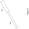
- FIGS 8 and 9 illustrate another example suture assembly 300 similar to suture assemblies 100 and 200.
- the suture assembly 300 includes a suture 380 fixed to a needle 310.
- the needle 310 is similar to needles 10 and 210, having a cylindrical body 320 and first and second end portions 340, 350, each having a sharp point 342, 352 and a depression 344, 354.
- the first and second sharp points 342, 352 are configured to pierce tissue such that the needle 310 may be used to suture tissue.
- Needle 310 may also include a lumen 322 extending through cylindrical body 320. Lumen 322 may extend through a central portion of cylindrical body 320 and may extend substantially perpendicular to the longitudinal axis X-X of cylindrical body 320.
- lumen 322 may extend through a non-central portion of cylindrical body 220 and/or be at an angle transverse to the longitudinal axis, but not perpendicular.
- Lumen 322 may include a first opening 324 on one side of cylindrical body 320 and a second opening (not shown) on the opposite side of cylindrical body 320 from the first opening 324.
- the first and second openings 324 may be identical.
- the lumen 322 is shown extending completely through the cylindrical body 320.
- the first, and/or second opening 324 may include a bevel or counter bore 327. In other examples, the first and/or second opening 324 may be flush with the exterior surface of the cylindrical body 320.
- the suture 380 may include a coupling member 390 fixed adjacent the terminal end 384 of the suture 380.
- the coupling member 390 may be inserted through the lumen 322 and fixed therein.
- the coupling member 390 may be a metal crimp tube.
- the crimp tube 390 may be placed over the suture 380 and then squeezed or crimped to fix it to the suture 380.
- the crimp tube 390 may then be inserted into the lumen 322 and fixed therein to secure the suture 380 to the needle 310, as shown in Figure 8 .
- the cylindrical body 320 and the crimp tube 390 may be metal and the crimp tube 390 may be welded or soldered within the lumen 322.
- the crimp tube 390 may be fixed within the lumen 322 with adhesive.
- FIG. 10 shows an alternative coupling member in the form of a wire 395 wrapped around the suture 380. As with the crimp tube 390, the wire 395 may be welded or soldered within the lumen 322 or fixed with adhesive.
- the needle 310 may include only the cylindrical body 320 and a single one of the first or second end portions 340, 350 with the sharp point 342, 352.
- the opposite end may be blunt.
- both the first and second end portions 340, 350 and their associated sharp points 342, 352 may be attached to the cylindrical body 320.
- the cylindrical body 320 may be made of the same or a different material from the first and/or second end portions 340, 350.
- the first and/or second end portions 340, 350 are made from a material that is more rigid than the material forming the cylindrical body 320.
- the entire needle 310 including the cylindrical body 320 and first and/or second end portion 340, 350 may be a single monolithic structure.
- the cylindrical body 320 and the first and/or second end portion 340, 350 may be solid.
- the suture 380 may include a knot or deformed (e.g., melted) region disposed within the coupling member 390 or above the coupling member 390, adjacent the outer surface of the cylindrical body 320.
- the suture 380 is fixedly coupled to needle 310 such that suture 380 remains within lumen 322 when a pulling force is applied to the suture 380, such as when using needle 310 to suture a patient.
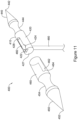
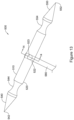
- FIGS 11 and 12 illustrate another example suture assembly 400 similar to suture assembly 100.
- the suture assembly 400 includes a suture 480 fixed to a needle 410.
- the needle 410 is similar to needle 10, having a cylindrical body 420 and first and second end portions 440, 450, each having a sharp point 442, 452 and a depression 444, 454.
- the first and second sharp points 442, 452 are configured to pierce tissue such that the needle 410 may be used to suture tissue.
- Needle 410 may also include a lumen 422 extending through cylindrical body 420. Lumen 422 may extend through a central portion of cylindrical body 420 and may extend substantially perpendicular to the longitudinal axis of cylindrical body 420.
- lumen 422 may extend through a non-central portion of cylindrical body 420 and/or be at an angle transverse to the longitudinal axis, but not perpendicular.
- Lumen 422 may include a first opening 424 on one side of cylindrical body 420 and a second opening (not shown) on the opposite side of cylindrical body 420 from the first opening 424.
- the lumen 422 may extend completely through the cylindrical body 420.
- the cylindrical body 420 may include a recess 428 in an outer surface configured to receive the first end region 482 of the suture 480.
- the suture 480 may be threaded through the lumen 422 and then the first end region 482 may be bent in an L shape and disposed within the recess 428.
- the second end portion 450 may include a sleeve portion 460 configured to slide over the cylindrical body 420 and compress the first end region 482 of the suture 480 within the recess 428.
- the recess 428 may be a channel that tapers as described for recess 28 in needle 10.
- First opening 424 of lumen 422 may be positioned within or otherwise in communication with recess 428.
- the sleeve portion 460 of the second end portion 450 may be a hollow cylinder or have a cavity configured to slide over the blunt end 427 of the cylindrical body 420, with a slot 462 extending through the wall in a longitudinal direction from one end towards the middle of the sleeve portion 460.
- the slot 462 may have a rounded end 464 configured to engage the suture 480 without damaging or cutting the suture 480.
- the recess 428 may have a depth measured transverse to the longitudinal axis that is less than the width of the suture 480.
- the sleeve portion 460 compresses the first end region 482 within the recess 428, thereby securing the suture 480 to the needle 410.
- the tapered shape of the recess 428 may provide for additional compression of the suture 80.
- the sleeve portion 460 may then be swaged onto the cylindrical body 420 to secure the second end portion 450 to the cylindrical body 420.
- the swaged region 466 of the sleeve portion 460 may include substantially the entire length of the sleeve portion 460. In other examples, only an end region of the sleeve portion 460 is swaged onto the cylindrical body 420. Swaging the sleeve portion 460 onto the cylindrical body 420 fixes the suture 480 to the needle 410 such that suture 480 remains within lumen 422 when a pulling force is applied to the suture 480, such as when using needle 410 to suture a patient.
- the sleeve portion 460 may be welded or soldered to the cylindrical body 420.
- adhesive or resin may be used in addition to the swaging, soldering, and/or welding to fix the sleeve portion 460 and/or suture 480 to the needle 410.
- the sleeve portion 460 may be an interference fit with the cylindrical body 420.
- the first end region 482 of the suture 480 may be deformed, e.g., melted, to conform to the shape of the recess 428 to aid in securing the suture to the needle 410.
- FIGS 13 and 14 illustrate another example suture assembly 500 similar to suture assemblies 100, 200, 300.
- the suture assembly 500 includes a suture 580 fixed to a needle 510.
- the needle 510 is similar to needles 10, 210, 310 having a cylindrical body 520 and first and second end portions 540, 550, each having a sharp point 542, 552 and a depression 544, 554.
- the first and second sharp points 542, 552 are configured to pierce tissue such that the needle 510 may be used to suture tissue.
- Needle 510 may also include a first lumen 522 extending through cylindrical body 520.
- First lumen 522 may extend through a central portion of cylindrical body 520 and may extend substantially perpendicular to the longitudinal axis of cylindrical body 520.
- first lumen 522 may extend through a non-central portion of cylindrical body 520.
- the first lumen 522 is shown extending completely through the cylindrical body 520. In some examples, the first lumen 522 may extend only part way through the cylindrical body 520.
- a second lumen 523 may extend through the cylindrical body 520 transverse to and intersecting the first lumen 522, as shown in Figure 14 .
- the suture 580 may be inserted through the first lumen 522.
- a first fixation member 592 may be inserted through the second lumen 523 from a first direction and a second fixation member 594 may be inserted through the second lumen 523 from a second direction.
- the first and second fixation members 592, 594 may be advanced until they engage and pinch the suture 580 between them.
- the first and second fixation members 592, 594 may be screws that threadingly engage an internally threaded second lumen 523.
- first and second fixation members 592, 594 may engage the second lumen 523 with a friction fit.
- the cylindrical body 520 and the first and second fixation members 592, 594 may be metal and the first and second fixation members 592, 594 may be welded or soldered within the second lumen 523.
- the first and second fixation members 592, 594 may be fixed within the second lumen 523 with adhesive.
- the needle 510 may include only the cylindrical body 520 and a single one of the first or second end portions 540, 550 with the sharp point 542, 552.
- the opposite end may be blunt.
- both the first and second end portions 540, 550 and their respective sharp point 542, 552 may be attached to the cylindrical body 520.
- the first and second sharp points 542, 552 are configured to pierce tissue such that the needle 510 may be used to suture tissue.
- the cylindrical body 520 may be attached to the first and/or second end portion 540, 550 via welding, soldering, swaging, or adhesive.
- the cylindrical body 520 may be made of the same or a different material from the first and/or second end portions 540, 550.
- first and/or second end portions 540, 550 are made from a material that is more rigid than the material forming the cylindrical body 520.
- the entire needle 510 including the cylindrical body 520 and first and/or second end portion 540, 550 may be a single monolithic structure.
- the cylindrical body 520 and the first and/or second end portion 540, 550 may be solid.
- the suture 580 may include a knot or deformed (e.g., melted) region disposed within the first lumen 522 or outside the first lumen 522, adjacent the outer surface of the cylindrical body 520.
- the suture 580 is fixedly coupled to needle 510 such that suture 580 remains within the first lumen 522 when a pulling force is applied to the suture 580, such as when using needle 510 to suture a patient.
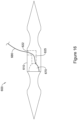
- FIGs 15 and 16 illustrate another example suture assembly 600 similar to suture assembly 100.
- the suture assembly 600 includes a suture 680 fixed to a needle 610.
- the needle 610 is similar to needle 10, having a cylindrical body 620 and first and second end portions 640, 650, each having a sharp point 642, 652 and a depression 644, 654.
- the first and second sharp points 642, 652 are configured to pierce tissue such that the needle 610 may be used to suture tissue.
- Needle 610 may also include a first lumen portion 622 extending part way into cylindrical body 620, as shown by the dashed lines in Figure 15 .
- First lumen portion 622 may extend into a central portion of cylindrical body 620 and may extend substantially perpendicular to the longitudinal axis of cylindrical body 620.
- first lumen portion 622 may extend through a non-central portion of cylindrical body 620 and/or be at an angle transverse to the longitudinal axis, but not perpendicular.
- the first lumen portion 622 may intersect a second lumen portion 625 extending longitudinally through the cylindrical body 620.
- the cylindrical body 620 may have a single lumen extending from the cavity 672 to an opening in the wall of the cylindrical body 620 (not shown). The single lumen may be curved or straight.
- the cylindrical body 620 may include a cavity 672 in an end face 674 opposite the sharp point 642.
- the cavity 672 is in communication with the second lumen portion 625 and may be configured to receive a protrusion 670 disposed on an end of the second end portion 650.
- the protrusion 670 may be received in the cavity 672 with a friction fit.
- the combination of first and second lumen portions 622, 625 and cavity 672 provide a pathway for the suture 680.
- the suture 680 may be threaded through the first lumen portion 622, second lumen portion 625, and into the cavity 672.
- the terminal end of the suture 680 may reside within the cavity 672.
- the protrusion 670 is then inserted into the cavity 672, thereby securing the suture 680 to the needle 610 such that suture 680 remains within the cavity 672 and the first and second lumen portions 622, 625 when a pulling force is applied to the suture 680, such as when using needle 610 to suture a patient.
- the protrusion 670 may be welded or soldered to the cavity 672 or the end face 674 of the cylindrical body 620.
- the protrusion 670 and/or the suture 680 may be fixed to the needle 610 with adhesive or resin.
- the end region of the suture 680 may be deformed, e.g., melted, to conform to the shape of one or more of the cavity 672, first lumen portion 622, or second lumen portion 625, to aid in securing the suture 680 to the needle 610.
- FIGs 17 and 18 illustrate additional example suture assemblies 700, 800 similar to suture assembly 300.
- the suture assembly 700 shown in Figure 17 includes a suture 780 fixed to a needle 710.
- the needle 710 is similar to needle 310, having a cylindrical body 720 and first and second end portions 740, 750, each having a sharp point 742, 752 and a depression 744, 754.
- the first and second sharp points 742, 752 are configured to pierce tissue such that the needle 710 may be used to suture tissue.
- Needle 710 may also include a lumen 722 extending through cylindrical body 720. Lumen 722 may extend through a central portion of cylindrical body 720 and may extend substantially perpendicular to the longitudinal axis of cylindrical body 720.
- lumen 722 may extend through a non-central portion of cylindrical body 720 and/or be at an angle transverse to the longitudinal axis, but not perpendicular.
- Lumen 722 may include a first opening 724 on one side of cylindrical body 720 and a second opening 726 on the opposite side of cylindrical body 720 from the first opening 724.
- the first and second openings 724, 726 may be identical.
- the lumen 722 is shown extending completely through the cylindrical body 720.
- the first, and/or second opening 724, 726 may include a bevel or counter bore as shown in Figure 8 .
- the first and/or second opening 724, 726 may be flush with the exterior surface of the cylindrical body 720 as shown in Figure 17 .
- the suture 780 may be inserted through the lumen 722 and a knot 785 tied in the end to prevent the suture 780 from being removed from the lumen 722 through the second opening 726, thereby securing the suture 780 to the needle 710, as shown in Figure 17 .
- the suture 780 may have a bulbous end, such that the end 785 is larger than the lumen 722.
- the bulbous end may be formed by deforming, or melting.
- the suture 780 may be fixed within the lumen 722 with adhesive or adhesive may be added to the knot 785 to secure the knot to the outer surface of the cylindrical body 720.
- Figure 18 shows a suture assembly 800 similar to suture assembly 700 but with a second lumen 821 spaced apart longitudinally from the first lumen 822.
- the suture assembly 800 shown in Figure 18 includes a suture 880 fixed to a needle 810.
- the needle 810 is similar to needle 710, having a cylindrical body 820 and first and second end portions 840, 850, each having a sharp point 842, 852 and a depression 844, 854.
- the first and second sharp points 842, 852 are configured to pierce tissue such that the needle 810 may be used to suture tissue.
- Needle 810 includes a first lumen 822 and a second lumen 821 extending through cylindrical body 820.
- Lumens 822, 821 may extend through a central portion of cylindrical body 820 and may extend substantially perpendicular to the longitudinal axis of cylindrical body 820. In other examples, lumens 822, 821 may extend through a non-central portion of cylindrical body 820 and/or be at an angle transverse to the longitudinal axis, but not perpendicular. Lumens 822, 821 may each include a first opening 824, 825 on one side of cylindrical body 820 and a second opening 826, 829 on the opposite side of cylindrical body 820 from the first opening 824, 825. The first openings 824, 825 and second openings 826, 829 may be identical. The first and second lumens 822, 821 are shown extending completely through the cylindrical body 820.
- first openings 824, 825, and/or second openings 826, 829 may include a bevel or counter bore as shown in Figure 8 .
- first and/or second openings may be flush with the exterior surface of the cylindrical body 820 as shown in Figure 18 .
- the suture 880 may be inserted through the second opening 826, into the first lumen 822, out the first opening 824 of the first lumen 822, across the outer surface of the cylindrical body 820, into the first opening 825 of the second lumen 821, through the second lumen 821 and out the second opening 829 of the second lumen 821.
- a knot 885 may be tied in the end to prevent the suture 880 from being removed from the lumens 822, 821 through the second opening 826, thereby securing the suture 880 to the needle 810 such that suture 880 remains within lumens 822, 821 when a pulling force is applied to the suture 880, such as when using needle 810 to suture a patient.
- the suture 880 may be fixed within the first and/or second lumen 822, 821 with adhesive or adhesive may be added to the knot 885 to secure the knot to the cylindrical body 820.
- the needles 710, 810 may include only the cylindrical body 720, 820 and a single one of the first end portion 740, 840 or second end portion 750, 850 with its associated sharp point 742, 842, 752, 852. The opposite end may be blunt.
- the needles 710, 810 may include both the first and second end portions 740, 840, 750, 850 and their associated sharp points, as illustrated.
- the cylindrical body 720, 820 may be made of the same or a different material from the first and/or second end portions 740, 840, 750, 850.
- first and/or second end portions 740, 840, 750, 850 are made from a material that is more rigid than the material forming the cylindrical body 720, 820.
- the entire needle 710, 810 including the cylindrical body 720, 820 and first and/or second end portion 740, 840, 750, 850 may be a single monolithic structure.
- the suture 80, 280, 380, 480, 580, 680, 780, 880 may be cylindrical and may be polyproplylene.
- the suture may be polyester, nylon, polyglycolic acid, polylactic acid, polymer materials, or any other absorbable or non-absorbable biocompatible material.
- variety of different metals may be used to make the needle 10, 210, 310, 410, 510, 610, 710, 810.
- suitable metals include titanium, stainless steel, magnesium, cobalt chromium and others.
- the devices described herein may include any suitable polymeric material, including biocompatible materials such as polyurethane or silicone.
- suitable polymers include but are not limited to polytetrafluoroethylene (PTFE), ethylene tetrafluoroethylene (ETFE), fluorinated ethylene propylene (FEP), polyoxymethylene (POM, for example, DELRIN ® available from DuPont), polyether block ester, polyurethane (for example, Polyurethane 85A), polypropylene (PP), polyvinylchloride (PVC), polyether-ester (for example, ARNITEL ® available from DSM Engineering Plastics), ether or ester based copolymers (for example, butylene/poly(alkylene ether) phthalate and/or other polyester elastomers such as HYTREL ® available from DuPont), polyamide (for example, DURETHAN ® available from Bayer or CRISTAMID ® available from Elf Atochem), e
- PTFE poly
Landscapes
- Health & Medical Sciences (AREA)
- Life Sciences & Earth Sciences (AREA)
- Surgery (AREA)
- Heart & Thoracic Surgery (AREA)
- Engineering & Computer Science (AREA)
- Biomedical Technology (AREA)
- Nuclear Medicine, Radiotherapy & Molecular Imaging (AREA)
- Medical Informatics (AREA)
- Molecular Biology (AREA)
- Animal Behavior & Ethology (AREA)
- General Health & Medical Sciences (AREA)
- Public Health (AREA)
- Veterinary Medicine (AREA)
- Surgical Instruments (AREA)
Description
- The disclosure is directed to devices for suturing tissue and more particularly to devices that work with an endoscope or similar device for endoscopically suturing tissue.
- A variety of endoscopic treatments may result in defects (or wounds) that are too large for known closure procedures. An assembly including a needle and a suture coupled to the needle may be used to suture tissue together. The tissue attachment method often involves piercing tissue with the needle and pulling on the needle to pull a suture attached to the needle through the hole created in the tissue. One way to couple a suture to a needle involves threading the suture through a hole in the needle and tying a knot at one end of the suture to prevent the end from passing through the hole of the needle. However, knot size can be inconsistent and may, in some examples, pull through the hole in the needle and uncouple the needle and suture, increasing surgical operation times, as operators may need to reassemble the needle and suture. Thus, there is a need for alternative suture and needle assemblies.
US 2004/0138706 A1 relates to suture anchors used to attach soft tissue to bone. - The invention is defined by the claims. The disclosure is directed to several alternative designs, materials and methods of devices for assembling a needle and suture. In an example, a medical device comprises a needle configured for use in suturing tissue, the needle comprising a cylindrical body extending along a longitudinal axis between first and second ends of the cylindrical body, a lumen extending through the cylindrical body transverse to longitudinal axis, the lumen having a first opening and a second opening opposite the first opening, and a first end portion at the first end of the cylindrical body, wherein the first end portion includes a first sharp point configured to pierce tissue, wherein an outer surface of the cylindrical body defines a first recess in communication with the first opening of the lumen and configured to receive an end region of a suture, and a sleeve configured to slide over the cylindrical body and compress the end region of the suture within the first recess.
- Alternatively or additionally, the sleeve has a slot in an outer wall thereof, the slot sized to receive a portion of the suture extending from the second opening of the lumen.
- In embodiments according to the invention, the first recess is a first channel extending longitudinally from the first opening of the lumen toward the first sharp point.
- Alternatively or additionally, the first channel tapers such that a first end of the first channel adjacent the first opening of the lumen has a first depth that is greater than a second depth at a second end of the first channel opposite the first end of the first channel.
- In embodiments according to the invention, the outer surface of the cylindrical body defines a second recess in communication with the first opening of the lumen, wherein the second recess is a second channel extending longitudinally from the first opening of the lumen in a direction away from the first sharp point.
- Alternatively or additionally, the medical device further comprises a second end portion at the second end of the cylindrical body, wherein the second end portion includes a second sharp point configured to pierce tissue.
- Alternatively or additionally, the cylindrical body and the first and second end portions are a single monolithic element.
- Alternatively or additionally, the single monolithic element is made of metal.
- Alternatively or additionally, the medical device further comprises a depression between the cylindrical body and the first sharp point.
- Alternatively or additionally, the medical device further comprises a suture having a first end region including a first terminal end, the first end region extending through the lumen and into the first recess, wherein the first terminal end is disposed within the first recess, wherein the sleeve is disposed over and compresses at least a portion of the first end region within the first recess, and the suture extends from the second opening of the lumen.
- Alternatively or additionally, the medical device further comprises a weld fixing the sleeve to the cylindrical body.
- Alternatively or additionally, the first end region of the suture is fixed to the cylindrical body with an adhesive or resin.
- Alternatively or additionally, the first end region of the suture within the first recess is deformed such that the suture conforms to a shape of the first recess.
- Alternatively or additionally, the sleeve is made of a heat shrinkable material.
- Alternatively or additionally, the sleeve includes a sharp point configured to pierce tissue.
- Alternatively or additionally, the sleeve includes a cavity configured to receive the second end of the cylindrical body.
- Alternatively or additionally, the cavity is configured to receive the second end of the cylindrical body in a friction fit.
- Alternatively or additionally, the sleeve is configured to be swaged onto the cylindrical body.
- Alternatively or additionally, the sleeve is configured to be fixed to the cylindrical body with an adhesive or weld.
- The disclosure may be more completely understood in consideration of the following description of in connection with the accompanying drawings, in which:
-
Figure 1 is a perspective view of an illustrative suture assembly in accordance with an example of the disclosure; -
Figure 2 is a perspective top view of a needle forming part of the illustrative suture assembly ofFigure 1 ; -
Figure 3 is a perspective bottom view of the needle ofFigure 2 ; -
Figure 4 is a perspective view of a sleeve forming part of the illustrative suture assembly ofFigure 1 ; -
Figure 5 is a cross-sectional view of the suture assembly ofFigure 1 , taken along the line 5-5; -
Figure 6 is a perspective bottom view of the illustrative suture assembly ofFigure 1 ; -
Figure 7A is a top view of an illustrative suture assembly in accordance with another example of the disclosure, in an open configuration; -
Figure 7B is a top view of the suture assembly ofFigure 7A in a closed configuration; -
Figure 8 is a perspective view of an illustrative suture assembly in accordance with another example of the disclosure; -
Figure 9 is a perspective view of the suture and coupling member ofFigure 7 ; -
Figure 10 is a perspective view of an alternative suture and coupling member ofFigure 8 ; -
Figure 11 is a perspective view of an illustrative suture assembly in accordance with another example of the disclosure, in a separated configuration; -
Figure 12 is a perspective view of the suture assembly ofFigure 11 in a connected configuration; -
Figure 13 is a top view of an illustrative suture assembly in accordance with another example of the disclosure; -
Figure 14 is a cross-sectional view of the suture assembly ofFigure 13 , taken along the line 14-14; -
Figure 15 is a top view of an illustrative suture assembly in accordance with another example of the disclosure, in a separated configuration; -
Figure 16 is a top view of the suture assembly ofFigure 15 , in a connected configuration; -
Figure 17 is a cross-sectional view of an illustrative suture assembly in accordance with another example of the disclosure; and -
Figure 18 is a cross-sectional view of an illustrative suture assembly in accordance with another example of the disclosure. - While the disclosure is amenable to various modifications and alternative forms, specifics thereof have been shown by way of example in the drawings and will be described in detail. It should be understood, however, that the intention is not to limit the invention to the particular embodiments described. On the contrary, the intention is to cover all modifications, equivalents, and alternatives falling within the scope of the appended claims.
- For the following defined terms, these definitions shall be applied, unless a different definition is given in the claims or elsewhere in this specification.
- Definitions of certain terms are provided below and shall be applied, unless a different definition is given in the claims or elsewhere in this specification.
- All numeric values are herein assumed to be modified by the term "about", whether or not explicitly indicated. The term "about" generally refers to a range of numbers that one of skill in the art would consider equivalent to the recited value (i.e., having the same function or result). In many instances, the term "about" may be indicative as including numbers that are rounded to the nearest significant figure.
- The recitation of numerical ranges by endpoints includes all numbers within that range (e.g., 1 to 5 includes 1, 1.5, 2, 2.75, 3, 3.80, 4, and 5).
- Although some suitable dimensions, ranges and/or values pertaining to various components, features and/or specifications are disclosed, one of skill in the art, incited by the present disclosure, would understand desired dimensions, ranges and/or values may deviate from those expressly disclosed.
- As used in this specification and the appended claims, the singular forms "a," "an," and "the" include or otherwise refer to singular as well as plural referents, unless the content clearly dictates otherwise. As used in this specification and the appended claims, the term "or" is generally employed to include "and/or," unless the content clearly dictates otherwise. As used in this specification and the appended claims, the terms "approximately" and "substantially" may indicate a range of values within +/- 5% of a stated value or position.
- The following detailed description should be read with reference to the drawings in which similar elements in different drawings are numbered the same. The detailed description and the drawings, which are not necessarily to scale, depict illustrative embodiments and are not intended to limit the scope of the disclosure. The illustrative embodiments depicted are intended only as exemplary. Selected features of any illustrative embodiment may be incorporated into an additional embodiment unless clearly stated to the contrary.
- The disclosure pertains to needles and suture assemblies that are configured to be used in combination with an endoscope or a similar delivery device for closing wounds within the body. In some instances, the needles and suture assemblies described herein may be configured such that they may be used with a suture based closure device such as that described in
U.S. Patent Publication No. 2018/0235604 . -
Figure 1 is a perspective view of anexemplary suture assembly 100 including aneedle 10,sleeve 60, andsuture 80. Theneedle 10 may include arecess 28 in an outer surface configured to receive afirst end region 82 of thesuture 80. Thesuture 80 may be threaded through a lumen 22 (shown inFigure 2 ) to extend substantially transverse to theneedle 10 as illustrated inFigure 1 . Thesleeve 60 may slide over theneedle 10 and compress thefirst end region 82 of thesuture 80 within therecess 28. - As shown in
Figure 2 , theneedle 10 may have acylindrical body 20 with a longitudinal axis X-X, afirst end portion 40 with a firstsharp point 42, and asecond end portion 50 with a secondsharp point 52. The first and secondsharp points needle 10 may be used to suture tissue. In some examples, theneedle 10 may include only thecylindrical body 20 and thefirst end portion 40 and only a singlesharp point 42. In such an example, the opposing end may be blunt. One or both of thefirst end portion 40 andsecond end portion 50 may include adepression depressions needle 10. In some examples,depressions cylindrical body 20 at an end of the curved surface. In some examples,depressions cylindrical body 20. In some examples,depressions lumen 22 ofcylindrical body 20. In some examples, eachdepression second end portions sharp point cylindrical body 20. In some examples, first andsecond end portions cylindrical body 20 by welding, soldering, swaging, or with adhesive. In other examples, thecylindrical body 20, and first andsecond end portions -
Needle 10 may also include alumen 22 extending throughcylindrical body 20 transverse to the longitudinal axis X-X.Lumen 22 may extend through a central portion ofcylindrical body 20 and may extend substantially perpendicular to the longitudinal axis X-X ofcylindrical body 20, as shown inFigure 2 . In other examples,lumen 22 may extend through a non-central portion ofcylindrical body 20 and/or be at an angle transverse to the longitudinal axis, but not perpendicular.Lumen 22 includes afirst opening 24 on one side ofcylindrical body 20 and a second opening 26 (shown inFigure 3 ) on the opposite side ofcylindrical body 20 from thefirst opening 24. In embodiments according to the invention,cylindrical body 20 includes afirst recess 28 andsecond recess 29 extending longitudinally from thelumen 22 on a radially-outer surface ofcylindrical body 20. In embodiments according to the invention, first andsecond recesses lumen 22. In some examples, therecess 28 is a channel that tapers such that afirst end 31 of therecess 28 adjacent thefirst opening 24 of thelumen 22 has a first depth that is greater than a second depth at asecond end 32 of therecess 28 opposite thefirst end 31. Thesecond recess 29 may be tapered in a similar manner asrecess 28. First opening 24 oflumen 22 may be positioned within or otherwise in communication withrecesses recesses first end region 82 of asuture 80, as shown inFigure 1 . -
Figure 3 shows the bottom of theneedle 10 inFigure 2 . Thelumen 22 is shown extending completely through thecylindrical body 20. In some examples, thesecond opening 26 may include a bevel or counter bore 27. In other examples, thesecond opening 26 may be flush with the exterior surface of thecylindrical body 20. -
Figure 4 shows thesleeve 60 as a hollow cylinder with two open ends and aslot 62 extending through the sleeve wall in a longitudinal direction from one end towards the middle of thesleeve 60. Theslot 62 may have arounded end 64 configured to engage thesuture 80 without damaging or cutting thesuture 80. -
Figure 5 is a cross-sectional view of theexample suture assembly 100 taken along line 5-5 ofFigure 1 . Thefirst end region 82 of thesuture 80 is threaded into thesecond opening 26 and out thefirst opening 24 of thelumen 22 in theneedle 10, and then bent in an L shape such that thefirst end region 82 and terminal end 84 of thesuture 80 reside within therecess 28. Alternatively, thefirst end region 82 of thesuture 80 may reside withinrecess 29. Thesleeve 60 slides over theneedle 10 and over thefirst end region 82 of thesuture 80. Therecess 28 may have a depth measured transverse to the longitudinal axis that is less than the width of thesuture 80, thereby compressing thesuture 80 within therecess 28 and securing thesuture 80 to theneedle 10. The tapered shape of therecess 28 may provide for additional compression of thesuture 80. - In some examples, the
needle 10 and thesleeve 60 may be metal, and thesleeve 60 may be welded to theneedle 10. For example, aweld 90 may be formed between theneedle 10 and thesleeve 60 on the bottom of theneedle 10, adjacent thesecond opening 26. In other examples, thesleeve 60 and/or thesuture 80 may be fixed to theneedle 10 with adhesive or resin. Adhesive or resin may be particularly suitable for fixing thesleeve 60 and/orsuture 80 to aneedle 10 formed from polymer or other non-metal biocompatible material. In other examples, thesleeve 60 may be made of a heat shrinkable material. Theheat shrink sleeve 60 may be slid over theneedle 10 andfirst end region 82 of thesuture 80. Heat is then applied causing theheat shrink sleeve 60 to shrink and compress thefirst end region 82 of thesuture 80 within therecess 28. In some examples, thesleeve 60 and theneedle 10 may be an interference fit. In some examples, thefirst end region 82 of thesuture 80 may be deformed, e.g., melted, to conform to the shape of therecess 28 to provide additional securement of the suture to theneedle 10. With any of the suture securing mechanisms described above, thesuture 80 is fixedly coupled toneedle 10 such thatsuture 80 remains withinlumen 22 when a pulling force is applied to thesuture 80 exiting thesecond opening 26, such as when usingneedle 10 to suture a patient. - As shown in
Figure 6 , when thesleeve 60 is disposed over theneedle 10, therounded end 64 of theslot 62 engages thesuture 80. In some examples, thesleeve 60 may be advanced until thesuture 80 is slightly pinched against a side of thelumen 22 and therounded end 64 of theslot 62. -
Figures 7A and7B illustrate anotherexample suture assembly 200 including aneedle 210 andsuture 280.Figures 7A and7B show a top or bottom view, with the opposite side being identical. Theneedle 210 is similar toneedle 10, having acylindrical body 220 and first andsecond end portions sharp point depression sharp points needle 210 may be used to suture tissue. Theneedle 210 may have aslot 222 extending through thecylindrical body 220 transverse to the longitudinal axis X-X, theslot 222 having a first opening on one side of thecylindrical body 220 and a second opening opposite the first opening. Theslot 222 may include acentral region 225 configured to receive thesuture 280, a firstelongated region 228, and a secondelongated region 229. The first and secondelongated regions central region 225. Thecentral region 225 may have a slightly rounded or semi-circular shape to match the outer shape of thesuture 280. Thecylindrical body 220 may havewalls 221 extending along theslot 222 that are deformable such that a radially inward force applied to thewalls 221 in the direction ofarrow 230, at thecentral region 225, causes thewalls 221 to deform inwardly where the force is applied, as shown inFigure 7B . In some examples, once deformed, thewalls 221 remain in the deformed configuration shown inFigure 7B , thereby permanently securing thesuture 280 to theneedle 210. Thewalls 221 may be deformed due to their thickness being thinner than a radial thickness of thecylindrical body 220. In other embodiments, thewalls 221 may be formed from a material more easily deformed than the remainder of thecylindrical body 220 and/or first andsecond end portions - Similar to
needle 10, theneedle 210 may include only thecylindrical body 220 and a single one of the first andsecond end portions sharp point second end portions sharp point cylindrical body 220 may be attached to the first and/orsecond end portion cylindrical body 220 may be made of the same or a different material from the first and/orsecond end portions second end portions cylindrical body 220. In other examples, theentire needle 210 including thecylindrical body 220 and first and/orsecond end portion cylindrical body 220 and the first and/orsecond end portion slot 222. In some examples, thesuture 280 may include a knot or deformed (e.g., melted) region disposed within thecentral region 225 of theslot 222 or above theslot 222, adjacent the outer surface of thecylindrical body 220. With any of the suture securing mechanisms described above, thesuture 280 is fixedly coupled toneedle 210 such thatsuture 280 remains within thecentral region 225 of theslot 222 when a pulling force is applied to thesuture 280, such as when usingneedle 210 to suture a patient. -
Figures 8 and9 illustrate anotherexample suture assembly 300 similar tosuture assemblies suture assembly 300 includes asuture 380 fixed to aneedle 310. Theneedle 310 is similar toneedles cylindrical body 320 and first andsecond end portions sharp point depression sharp points needle 310 may be used to suture tissue.Needle 310 may also include alumen 322 extending throughcylindrical body 320.Lumen 322 may extend through a central portion ofcylindrical body 320 and may extend substantially perpendicular to the longitudinal axis X-X ofcylindrical body 320. In other examples,lumen 322 may extend through a non-central portion ofcylindrical body 220 and/or be at an angle transverse to the longitudinal axis, but not perpendicular.Lumen 322 may include a first opening 324 on one side ofcylindrical body 320 and a second opening (not shown) on the opposite side ofcylindrical body 320 from the first opening 324. The first and second openings 324 may be identical. Thelumen 322 is shown extending completely through thecylindrical body 320. In some examples, the first, and/or second opening 324 may include a bevel orcounter bore 327. In other examples, the first and/or second opening 324 may be flush with the exterior surface of thecylindrical body 320. - The
suture 380 may include acoupling member 390 fixed adjacent theterminal end 384 of thesuture 380. Thecoupling member 390 may be inserted through thelumen 322 and fixed therein. In the example shown inFigure 9 , thecoupling member 390 may be a metal crimp tube. Thecrimp tube 390 may be placed over thesuture 380 and then squeezed or crimped to fix it to thesuture 380. Thecrimp tube 390 may then be inserted into thelumen 322 and fixed therein to secure thesuture 380 to theneedle 310, as shown inFigure 8 . In some examples, thecylindrical body 320 and thecrimp tube 390 may be metal and thecrimp tube 390 may be welded or soldered within thelumen 322. In other examples, thecrimp tube 390 may be fixed within thelumen 322 with adhesive.FIG. 10 shows an alternative coupling member in the form of awire 395 wrapped around thesuture 380. As with thecrimp tube 390, thewire 395 may be welded or soldered within thelumen 322 or fixed with adhesive. - Similar to
needle 10, theneedle 310 may include only thecylindrical body 320 and a single one of the first orsecond end portions sharp point second end portions sharp points cylindrical body 320. Thecylindrical body 320 may be made of the same or a different material from the first and/orsecond end portions second end portions cylindrical body 320. In other examples, theentire needle 310 including thecylindrical body 320 and first and/orsecond end portion cylindrical body 320 and the first and/orsecond end portion - In some examples, the
suture 380 may include a knot or deformed (e.g., melted) region disposed within thecoupling member 390 or above thecoupling member 390, adjacent the outer surface of thecylindrical body 320. With any of the suture securing mechanisms described above, thesuture 380 is fixedly coupled toneedle 310 such thatsuture 380 remains withinlumen 322 when a pulling force is applied to thesuture 380, such as when usingneedle 310 to suture a patient. -
Figures 11 and12 illustrate anotherexample suture assembly 400 similar tosuture assembly 100. Thesuture assembly 400 includes asuture 480 fixed to aneedle 410. Theneedle 410 is similar toneedle 10, having acylindrical body 420 and first andsecond end portions sharp point depression sharp points needle 410 may be used to suture tissue.Needle 410 may also include alumen 422 extending throughcylindrical body 420.Lumen 422 may extend through a central portion ofcylindrical body 420 and may extend substantially perpendicular to the longitudinal axis ofcylindrical body 420. In other examples,lumen 422 may extend through a non-central portion ofcylindrical body 420 and/or be at an angle transverse to the longitudinal axis, but not perpendicular.Lumen 422 may include afirst opening 424 on one side ofcylindrical body 420 and a second opening (not shown) on the opposite side ofcylindrical body 420 from thefirst opening 424. Thelumen 422 may extend completely through thecylindrical body 420. - The
cylindrical body 420 may include arecess 428 in an outer surface configured to receive thefirst end region 482 of thesuture 480. Thesuture 480 may be threaded through thelumen 422 and then thefirst end region 482 may be bent in an L shape and disposed within therecess 428. Thesecond end portion 450 may include asleeve portion 460 configured to slide over thecylindrical body 420 and compress thefirst end region 482 of thesuture 480 within therecess 428. Therecess 428 may be a channel that tapers as described forrecess 28 inneedle 10. First opening 424 oflumen 422 may be positioned within or otherwise in communication withrecess 428. Thesleeve portion 460 of thesecond end portion 450 may be a hollow cylinder or have a cavity configured to slide over theblunt end 427 of thecylindrical body 420, with aslot 462 extending through the wall in a longitudinal direction from one end towards the middle of thesleeve portion 460. Theslot 462 may have arounded end 464 configured to engage thesuture 480 without damaging or cutting thesuture 480. Therecess 428 may have a depth measured transverse to the longitudinal axis that is less than the width of thesuture 480. As thesleeve portion 460 slides over thecylindrical body 420 and over thefirst end region 482 of thesuture 480, thesleeve portion 460 compresses thefirst end region 482 within therecess 428, thereby securing thesuture 480 to theneedle 410. The tapered shape of therecess 428 may provide for additional compression of thesuture 80. - The
sleeve portion 460 may then be swaged onto thecylindrical body 420 to secure thesecond end portion 450 to thecylindrical body 420. As shown inFigure 12 , the swagedregion 466 of thesleeve portion 460 may include substantially the entire length of thesleeve portion 460. In other examples, only an end region of thesleeve portion 460 is swaged onto thecylindrical body 420. Swaging thesleeve portion 460 onto thecylindrical body 420 fixes thesuture 480 to theneedle 410 such thatsuture 480 remains withinlumen 422 when a pulling force is applied to thesuture 480, such as when usingneedle 410 to suture a patient. - In addition to swaging the
sleeve portion 460 onto thecylindrical body 420, in some examples, thesleeve portion 460 may be welded or soldered to thecylindrical body 420. In other examples, adhesive or resin may be used in addition to the swaging, soldering, and/or welding to fix thesleeve portion 460 and/orsuture 480 to theneedle 410. In other examples, thesleeve portion 460 may be an interference fit with thecylindrical body 420. In other examples, thefirst end region 482 of thesuture 480 may be deformed, e.g., melted, to conform to the shape of therecess 428 to aid in securing the suture to theneedle 410. -
Figures 13 and14 illustrate anotherexample suture assembly 500 similar tosuture assemblies suture assembly 500 includes asuture 580 fixed to aneedle 510. Theneedle 510 is similar toneedles cylindrical body 520 and first andsecond end portions sharp point depression sharp points needle 510 may be used to suture tissue.Needle 510 may also include afirst lumen 522 extending throughcylindrical body 520.First lumen 522 may extend through a central portion ofcylindrical body 520 and may extend substantially perpendicular to the longitudinal axis ofcylindrical body 520. In other examples,first lumen 522 may extend through a non-central portion ofcylindrical body 520. Thefirst lumen 522 is shown extending completely through thecylindrical body 520. In some examples, thefirst lumen 522 may extend only part way through thecylindrical body 520. - A
second lumen 523 may extend through thecylindrical body 520 transverse to and intersecting thefirst lumen 522, as shown inFigure 14 . Thesuture 580 may be inserted through thefirst lumen 522. Afirst fixation member 592 may be inserted through thesecond lumen 523 from a first direction and asecond fixation member 594 may be inserted through thesecond lumen 523 from a second direction. The first andsecond fixation members suture 580 between them. In some examples, the first andsecond fixation members second lumen 523. In other examples, the first andsecond fixation members second lumen 523 with a friction fit. In some examples, thecylindrical body 520 and the first andsecond fixation members second fixation members second lumen 523. In other examples, the first andsecond fixation members second lumen 523 with adhesive. - Similar to
needle 10, theneedle 510 may include only thecylindrical body 520 and a single one of the first orsecond end portions sharp point second end portions sharp point cylindrical body 520. The first and secondsharp points needle 510 may be used to suture tissue. In either case, thecylindrical body 520 may be attached to the first and/orsecond end portion cylindrical body 520 may be made of the same or a different material from the first and/orsecond end portions second end portions cylindrical body 520. In other examples, theentire needle 510 including thecylindrical body 520 and first and/orsecond end portion cylindrical body 520 and the first and/orsecond end portion - In some examples, the
suture 580 may include a knot or deformed (e.g., melted) region disposed within thefirst lumen 522 or outside thefirst lumen 522, adjacent the outer surface of thecylindrical body 520. With any of the suture securing mechanisms described above, thesuture 580 is fixedly coupled toneedle 510 such thatsuture 580 remains within thefirst lumen 522 when a pulling force is applied to thesuture 580, such as when usingneedle 510 to suture a patient. -
Figures 15 and16 illustrate anotherexample suture assembly 600 similar tosuture assembly 100. Thesuture assembly 600 includes asuture 680 fixed to aneedle 610. Theneedle 610 is similar toneedle 10, having acylindrical body 620 and first andsecond end portions sharp point depression sharp points needle 610 may be used to suture tissue.Needle 610 may also include afirst lumen portion 622 extending part way intocylindrical body 620, as shown by the dashed lines inFigure 15 .First lumen portion 622 may extend into a central portion ofcylindrical body 620 and may extend substantially perpendicular to the longitudinal axis ofcylindrical body 620. In other examples,first lumen portion 622 may extend through a non-central portion ofcylindrical body 620 and/or be at an angle transverse to the longitudinal axis, but not perpendicular. Thefirst lumen portion 622 may intersect asecond lumen portion 625 extending longitudinally through thecylindrical body 620. In other examples, thecylindrical body 620 may have a single lumen extending from thecavity 672 to an opening in the wall of the cylindrical body 620 (not shown). The single lumen may be curved or straight. - The
cylindrical body 620 may include acavity 672 in anend face 674 opposite thesharp point 642. Thecavity 672 is in communication with thesecond lumen portion 625 and may be configured to receive aprotrusion 670 disposed on an end of thesecond end portion 650. Theprotrusion 670 may be received in thecavity 672 with a friction fit. The combination of first andsecond lumen portions cavity 672 provide a pathway for thesuture 680. Thesuture 680 may be threaded through thefirst lumen portion 622,second lumen portion 625, and into thecavity 672. The terminal end of thesuture 680 may reside within thecavity 672. As shown inFigure 16 , theprotrusion 670 is then inserted into thecavity 672, thereby securing thesuture 680 to theneedle 610 such thatsuture 680 remains within thecavity 672 and the first andsecond lumen portions suture 680, such as when usingneedle 610 to suture a patient. - In addition to the friction fit of the
protrusion 670 within thecavity 672, theprotrusion 670 may be welded or soldered to thecavity 672 or theend face 674 of thecylindrical body 620. In other examples, theprotrusion 670 and/or thesuture 680 may be fixed to theneedle 610 with adhesive or resin. In other examples, the end region of thesuture 680 may be deformed, e.g., melted, to conform to the shape of one or more of thecavity 672,first lumen portion 622, orsecond lumen portion 625, to aid in securing thesuture 680 to theneedle 610. -
Figures 17 and18 illustrate additionalexample suture assemblies suture assembly 300. Thesuture assembly 700 shown inFigure 17 includes asuture 780 fixed to aneedle 710. Theneedle 710 is similar toneedle 310, having acylindrical body 720 and first andsecond end portions sharp point depression sharp points needle 710 may be used to suture tissue.Needle 710 may also include alumen 722 extending throughcylindrical body 720.Lumen 722 may extend through a central portion ofcylindrical body 720 and may extend substantially perpendicular to the longitudinal axis ofcylindrical body 720. In other examples,lumen 722 may extend through a non-central portion ofcylindrical body 720 and/or be at an angle transverse to the longitudinal axis, but not perpendicular.Lumen 722 may include afirst opening 724 on one side ofcylindrical body 720 and asecond opening 726 on the opposite side ofcylindrical body 720 from thefirst opening 724. The first andsecond openings lumen 722 is shown extending completely through thecylindrical body 720. In some examples, the first, and/orsecond opening Figure 8 . In other examples, the first and/orsecond opening cylindrical body 720 as shown inFigure 17 . - The
suture 780 may be inserted through thelumen 722 and aknot 785 tied in the end to prevent thesuture 780 from being removed from thelumen 722 through thesecond opening 726, thereby securing thesuture 780 to theneedle 710, as shown inFigure 17 . In some embodiments, thesuture 780 may have a bulbous end, such that theend 785 is larger than thelumen 722. For example, the bulbous end may be formed by deforming, or melting. In some examples, thesuture 780 may be fixed within thelumen 722 with adhesive or adhesive may be added to theknot 785 to secure the knot to the outer surface of thecylindrical body 720. -
Figure 18 shows asuture assembly 800 similar tosuture assembly 700 but with asecond lumen 821 spaced apart longitudinally from thefirst lumen 822. Thesuture assembly 800 shown inFigure 18 includes asuture 880 fixed to aneedle 810. Theneedle 810 is similar toneedle 710, having acylindrical body 820 and first andsecond end portions sharp point depression sharp points needle 810 may be used to suture tissue.Needle 810 includes afirst lumen 822 and asecond lumen 821 extending throughcylindrical body 820.Lumens cylindrical body 820 and may extend substantially perpendicular to the longitudinal axis ofcylindrical body 820. In other examples,lumens cylindrical body 820 and/or be at an angle transverse to the longitudinal axis, but not perpendicular.Lumens first opening cylindrical body 820 and asecond opening cylindrical body 820 from thefirst opening first openings second openings second lumens cylindrical body 820. In some examples, thefirst openings second openings Figure 8 . In other examples, the first and/or second openings may be flush with the exterior surface of thecylindrical body 820 as shown inFigure 18 . - The
suture 880 may be inserted through thesecond opening 826, into thefirst lumen 822, out thefirst opening 824 of thefirst lumen 822, across the outer surface of thecylindrical body 820, into thefirst opening 825 of thesecond lumen 821, through thesecond lumen 821 and out thesecond opening 829 of thesecond lumen 821. Aknot 885 may be tied in the end to prevent thesuture 880 from being removed from thelumens second opening 826, thereby securing thesuture 880 to theneedle 810 such thatsuture 880 remains withinlumens suture 880, such as when usingneedle 810 to suture a patient. In some examples, thesuture 880 may be fixed within the first and/orsecond lumen knot 885 to secure the knot to thecylindrical body 820. - Similar to
needle 10, theneedles cylindrical body first end portion second end portion sharp point needles second end portions cylindrical body second end portions second end portions cylindrical body entire needle cylindrical body second end portion - It will be appreciated that a variety of different materials may be used in forming the devices described herein. The
suture needle - Those skilled in the art will recognize that the present disclosure may be manifested in a variety of forms other than the specific embodiments described and contemplated herein. Accordingly, departure in form and detail may be made without departing from the scope of the present disclosure as described in the appended claims.
Claims (11)
- A medical device (100) comprising:a needle (10) configured for use in suturing tissue, the needle comprising:a cylindrical body (20) extending along a longitudinal axis (X-X) between first and second ends of the cylindrical body;a lumen (22) extending through the cylindrical body transverse to the longitudinal axis, the lumen having a first opening (24) and a second opening (26) opposite the first opening; anda first end portion (40) at the first end of the cylindrical body, wherein the first end portion includes a first sharp point (42) configured to pierce tissue;wherein an outer surface of the cylindrical body defines a first recess (28) in communication with the first opening of the lumen and configured to receive an end region (82) of a suture (80); anda sleeve (60) configured to slide over the cylindrical body and compress the end region of the suture within the first recess,wherein the first recess is a first channel extending longitudinally from the first opening of the lumen toward the first sharp point,wherein the outer surface of the cylindrical body defines a second recess (29) in communication with the first opening of the lumen, wherein the second recess is a second channel extending longitudinally from the first opening of the lumen in a direction away from the first sharp point.
- The medical device of claim 1, wherein the sleeve has a slot (62) in an outer wall thereof, the slot sized to receive a portion of the suture extending from the second opening of the lumen.
- The medical device of claim 1, wherein the first channel tapers such that a first end (31) of the first channel adjacent the first opening of the lumen has a first depth that is greater than a second depth at a second end (32) of the first channel opposite the first end of the first channel.
- The medical device of any one of claims 1-3, further comprising a second end portion (50) at the second end of the cylindrical body, wherein the second end portion includes a second sharp point (52) configured to pierce tissue.
- The medical device of any one of claims 1-4, further comprising a suture (80) having a first end region (82) including a first terminal end (84), the first end region extending through the lumen and into the first recess, wherein the first terminal end is disposed within the first recess, wherein the sleeve is disposed over and compresses at least a portion of the first end region within the first recess, and the suture extends from the second opening of the lumen.
- The medical device of claim 5, wherein the first end region of the suture within the first recess is deformed such that the suture conforms to a shape of the first recess.
- The medical device of any one of claims 1-6, wherein the sleeve is made of a heat shrinkable material.
- The medical device of claim 1, wherein the sleeve includes a sharp point configured to pierce tissue.
- The medical device of claim 8, wherein the sleeve includes a cavity configured to receive the second end of the cylindrical body.
- The medical device of claim 9, wherein the sleeve has a slot in an outer wall thereof, the slot sized to receive a portion of the suture extending from the second opening of the lumen.
- The medical device of claim 8, wherein the sleeve is configured to be swaged onto the cylindrical body.
Applications Claiming Priority (3)
| Application Number | Priority Date | Filing Date | Title |
|---|---|---|---|
| US201862727783P | 2018-09-06 | 2018-09-06 | |
| US201962848885P | 2019-05-16 | 2019-05-16 | |
| PCT/US2019/049774 WO2020051348A1 (en) | 2018-09-06 | 2019-09-05 | Endoscopic suturing needle and suture assembly attachment methods |
Publications (2)
| Publication Number | Publication Date |
|---|---|
| EP3846699A1 EP3846699A1 (en) | 2021-07-14 |
| EP3846699B1 true EP3846699B1 (en) | 2024-11-27 |
Family
ID=67997709
Family Applications (2)
| Application Number | Title | Priority Date | Filing Date |
|---|---|---|---|
| EP19770244.2A Active EP3846699B1 (en) | 2018-09-06 | 2019-09-05 | Endoscopic suturing needle |
| EP19773238.1A Withdrawn EP3846700A1 (en) | 2018-09-06 | 2019-09-05 | Suture needle devices and suture attachment methods |
Family Applications After (1)
| Application Number | Title | Priority Date | Filing Date |
|---|---|---|---|
| EP19773238.1A Withdrawn EP3846700A1 (en) | 2018-09-06 | 2019-09-05 | Suture needle devices and suture attachment methods |
Country Status (7)
| Country | Link |
|---|---|
| US (3) | US11278272B2 (en) |
| EP (2) | EP3846699B1 (en) |
| JP (2) | JP7130852B2 (en) |
| KR (1) | KR102596714B1 (en) |
| CN (4) | CN120324048A (en) |
| CA (1) | CA3110413C (en) |
| WO (2) | WO2020051348A1 (en) |
Families Citing this family (4)
| Publication number | Priority date | Publication date | Assignee | Title |
|---|---|---|---|---|
| WO2020051348A1 (en) * | 2018-09-06 | 2020-03-12 | Boston Scientific Scimed, Inc. | Endoscopic suturing needle and suture assembly attachment methods |
| EP3922189B1 (en) | 2020-06-08 | 2025-04-23 | Suturion AB | Crimping device and method |
| CN116509479B (en) * | 2023-04-18 | 2023-11-07 | 南京思脉德医疗科技有限公司 | Crimping connector of vascular suture device and process for fixing suture line |
| CN116421244B (en) * | 2023-06-13 | 2023-09-05 | 二零二零(北京)医疗科技有限公司 | Suture line structure in medical operation and manufacturing process |
Family Cites Families (106)
| Publication number | Priority date | Publication date | Assignee | Title |
|---|---|---|---|---|
| US3880167A (en) * | 1974-01-28 | 1975-04-29 | Charles W Hardwick | Surgical needle apparatus |
| JPS5216294U (en) * | 1975-07-23 | 1977-02-04 | ||
| US5358498A (en) * | 1990-02-01 | 1994-10-25 | Deknatel Technology Corporation, Inc. | Needled suture |
| GB9218754D0 (en) | 1992-09-04 | 1992-10-21 | Univ London | Device for use in securing a thread |
| US5478344A (en) | 1993-10-08 | 1995-12-26 | United States Surgical Corporation | Surgical suturing apparatus with loading mechanism |
| CA2133377C (en) * | 1993-10-08 | 2004-09-14 | H. Jonathan Tovey | Surgical suturing apparatus with loading mechanism |
| US6086608A (en) | 1996-02-22 | 2000-07-11 | Smith & Nephew, Inc. | Suture collet |
| US5693071A (en) | 1996-01-23 | 1997-12-02 | United States Surgical Corporation | Tapered surgical needles and surgical incision members |
| US5865836A (en) | 1996-09-20 | 1999-02-02 | United States Surgical Corporation | Needle-suture combination |
| CA2224366C (en) * | 1996-12-11 | 2006-10-31 | Ethicon, Inc. | Meniscal repair device |
| US6200329B1 (en) | 1998-08-31 | 2001-03-13 | Smith & Nephew, Inc. | Suture collet |
| US6494888B1 (en) | 1999-06-22 | 2002-12-17 | Ndo Surgical, Inc. | Tissue reconfiguration |
| US8287554B2 (en) | 1999-06-22 | 2012-10-16 | Ethicon Endo-Surgery, Inc. | Method and devices for tissue reconfiguration |
| US6663639B1 (en) | 1999-06-22 | 2003-12-16 | Ndo Surgical, Inc. | Methods and devices for tissue reconfiguration |
| US6835200B2 (en) | 1999-06-22 | 2004-12-28 | Ndo Surgical. Inc. | Method and devices for tissue reconfiguration |
| US6821285B2 (en) | 1999-06-22 | 2004-11-23 | Ndo Surgical, Inc. | Tissue reconfiguration |
| US7846180B2 (en) | 1999-06-22 | 2010-12-07 | Ethicon Endo-Surgery, Inc. | Tissue fixation devices and methods of fixing tissue |
| US6506196B1 (en) | 1999-06-22 | 2003-01-14 | Ndo Surgical, Inc. | Device and method for correction of a painful body defect |
| ATE329531T1 (en) | 1999-07-02 | 2006-07-15 | Quickpass Inc | SURGICAL SEWING DEVICE |
| AU1233301A (en) | 1999-10-26 | 2001-05-08 | H. Randall Craig | Helical suture instrument |
| US7993368B2 (en) | 2003-03-13 | 2011-08-09 | C.R. Bard, Inc. | Suture clips, delivery devices and methods |
| EP1284661B1 (en) | 2000-05-19 | 2013-08-14 | C.R. Bard, Inc. | Tissue capturing and suturing device |
| US7220266B2 (en) | 2000-05-19 | 2007-05-22 | C. R. Bard, Inc. | Tissue capturing and suturing device and method |
| US6554845B1 (en) | 2000-09-15 | 2003-04-29 | PARÉ Surgical, Inc. | Suturing apparatus and method |
| US6755843B2 (en) | 2000-09-29 | 2004-06-29 | Olympus Optical Co., Ltd. | Endoscopic suturing device |
| US6719763B2 (en) | 2000-09-29 | 2004-04-13 | Olympus Optical Co., Ltd. | Endoscopic suturing device |
| US7232445B2 (en) | 2000-12-06 | 2007-06-19 | Id, Llc | Apparatus for the endoluminal treatment of gastroesophageal reflux disease (GERD) |
| US6569085B2 (en) | 2001-08-16 | 2003-05-27 | Syntheon, Llc | Methods and apparatus for delivering a medical instrument over an endoscope while the endoscope is in a body lumen |
| US7727246B2 (en) | 2000-12-06 | 2010-06-01 | Ethicon Endo-Surgery, Inc. | Methods for endoluminal treatment |
| US8062314B2 (en) | 2000-12-06 | 2011-11-22 | Ethicon Endo-Surgery, Inc. | Methods for the endoluminal treatment of gastroesophageal reflux disease (GERD) |
| US7235086B2 (en) | 2001-02-02 | 2007-06-26 | Lsi Solutions, Inc. | Crimping instrument with motion limiting feature |
| US8313496B2 (en) | 2001-02-02 | 2012-11-20 | Lsi Solutions, Inc. | System for endoscopic suturing |
| US6997931B2 (en) | 2001-02-02 | 2006-02-14 | Lsi Solutions, Inc. | System for endoscopic suturing |
| US6808491B2 (en) | 2001-05-21 | 2004-10-26 | Syntheon, Llc | Methods and apparatus for on-endoscope instruments having end effectors and combinations of on-endoscope and through-endoscope instruments |
| US7144401B2 (en) | 2001-06-07 | 2006-12-05 | Olympus Optical Co., Ltd. | Suturing device for endoscope |
| US6746457B2 (en) | 2001-12-07 | 2004-06-08 | Abbott Laboratories | Snared suture trimmer |
| US8211123B2 (en) | 2001-12-21 | 2012-07-03 | Abbott Laboratories | Suture trimmer |
| US7094246B2 (en) | 2001-12-07 | 2006-08-22 | Abbott Laboratories | Suture trimmer |
| US7918867B2 (en) | 2001-12-07 | 2011-04-05 | Abbott Laboratories | Suture trimmer |
| US6740030B2 (en) | 2002-01-04 | 2004-05-25 | Vision Sciences, Inc. | Endoscope assemblies having working channels with reduced bending and stretching resistance |
| US7344545B2 (en) | 2002-01-30 | 2008-03-18 | Olympus Corporation | Endoscopic suturing system |
| US7530985B2 (en) | 2002-01-30 | 2009-05-12 | Olympus Corporation | Endoscopic suturing system |
| US7618425B2 (en) | 2002-01-30 | 2009-11-17 | Olympus Corporation | Endoscopic suturing system |
| JP3890589B2 (en) | 2002-04-15 | 2007-03-07 | ニプロ株式会社 | Intracardiac suture device |
| US6923807B2 (en) | 2002-06-27 | 2005-08-02 | Ethicon, Inc. | Helical device and method for aiding the ablation and assessment of tissue |
| JP4373146B2 (en) | 2002-07-11 | 2009-11-25 | オリンパス株式会社 | Endoscopic suturing device |
| US6936054B2 (en) | 2002-07-22 | 2005-08-30 | Boston Scientific Scimed, Inc. | Placing sutures |
| US6908427B2 (en) | 2002-12-30 | 2005-06-21 | PARÉ Surgical, Inc. | Flexible endoscope capsule |
| US7517357B2 (en) * | 2003-01-09 | 2009-04-14 | Linvatec Biomaterials | Knotless suture anchor |
| US8066718B2 (en) * | 2003-03-18 | 2011-11-29 | Depuy Mitek, Inc. | Expandable needle suture apparatus and associated handle assembly |
| US8585714B2 (en) * | 2003-03-18 | 2013-11-19 | Depuy Mitek, Llc | Expandable needle suture apparatus and associated handle assembly with rotational suture manipulation system |
| WO2004103189A1 (en) | 2003-05-16 | 2004-12-02 | C.R. Bard, Inc. | Single intubation, multi-stitch endoscopic suturing system |
| EP1667749B1 (en) | 2003-09-15 | 2009-08-05 | Super Dimension Ltd. | System of accessories for use with bronchoscopes |
| JP4505244B2 (en) | 2003-09-30 | 2010-07-21 | オリンパス株式会社 | Endoscopic forceps adapter |
| US7347863B2 (en) | 2004-05-07 | 2008-03-25 | Usgi Medical, Inc. | Apparatus and methods for manipulating and securing tissue |
| US7361180B2 (en) | 2004-05-07 | 2008-04-22 | Usgi Medical, Inc. | Apparatus for manipulating and securing tissue |
| US20070219586A1 (en) * | 2004-01-23 | 2007-09-20 | Chalam Mahadevan | Suture Needle and Suture Assembly |
| JP4643328B2 (en) | 2004-04-07 | 2011-03-02 | オリンパス株式会社 | Medical ligature suturing device |
| US8057511B2 (en) | 2004-05-07 | 2011-11-15 | Usgi Medical, Inc. | Apparatus and methods for positioning and securing anchors |
| US20050250985A1 (en) | 2004-05-07 | 2005-11-10 | Usgi Medical Inc. | Self-locking removable apparatus and methods for manipulating and securing tissue |
| FR2880532B1 (en) | 2005-01-07 | 2008-03-21 | Peter Cumbo | SURGICAL NEEDLE AND THREAD USED WITH THIS NEEDLE |
| ITGE20050033A1 (en) * | 2005-05-18 | 2006-11-19 | Sergio Capurro | NEEDLE WITH TWO ATRAUMATIC POINTS FOR SURGICAL SUTURE CONSTITUTED BY TWO OR MORE MODULAR ELEMENTS. |
| US7766925B2 (en) | 2005-06-13 | 2010-08-03 | Ethicon Endo-Surgery, Inc. | Surgical suturing apparatus |
| DE202005022017U1 (en) * | 2005-12-22 | 2012-05-10 | Hugh S., jun. West | Bone Anchor with threaded structure optimized for fixation in cortical bone tissue and cancellous bone tissue |
| US8105355B2 (en) | 2006-05-18 | 2012-01-31 | C.R. Bard, Inc. | Suture lock fastening device |
| US20070270908A1 (en) | 2006-05-19 | 2007-11-22 | Stokes Michael J | Suture locking method |
| CA2659326C (en) | 2006-08-01 | 2011-02-15 | Wilson-Cook Medical Inc. | Improved system and method for endoscopic treatment of tissue |
| US20080086148A1 (en) | 2006-10-04 | 2008-04-10 | Endogastric Solutions, Inc. | Assemblies for deploying fasteners in tissue and snares for use in such assemblies |
| US8226667B2 (en) | 2006-10-05 | 2012-07-24 | Tyco Healthcare Group Lp | Axial stitching device |
| US8702729B2 (en) | 2006-10-13 | 2014-04-22 | Boston Scientific Scimed, Inc. | Placing multiple sutures |
| US9033999B2 (en) * | 2006-12-04 | 2015-05-19 | Implicitcare, Llc | Surgical threading device with removable suture |
| WO2008098124A1 (en) | 2007-02-07 | 2008-08-14 | Boston Scientific Scimed, Inc. | Attachment clamp |
| JP5498935B2 (en) | 2007-03-30 | 2014-05-21 | クック メディカル テクノロジーズ エルエルシー | Endoscope fixation system |
| WO2009052438A2 (en) | 2007-10-19 | 2009-04-23 | Guided Delivery Systems Inc. | Devices for termination of tethers |
| WO2009089101A2 (en) | 2008-01-03 | 2009-07-16 | Wilson-Cook Medical, Inc. | Medical systems, devices and methods for endoscopically suturing perforations |
| US20090259105A1 (en) | 2008-04-10 | 2009-10-15 | Miyano Hiromichi | Medical treatment system and suturing method |
| JP5763531B2 (en) | 2008-06-17 | 2015-08-12 | アポロ エンドサージェリー,インコーポレイティド | Endoscopic suture system |
| US9867610B2 (en) | 2008-06-17 | 2018-01-16 | Apollo Endosurgery Us, Inc. | Endoscopic suturing system with retained end cap |
| US9486126B2 (en) | 2008-06-17 | 2016-11-08 | Apollo Endosurgery, Inc. | Endoscopic helix tissue grasping device |
| CA2738426C (en) | 2008-09-29 | 2016-03-15 | C.R. Bard, Inc. | Endoscopic suturing device |
| US20100137681A1 (en) | 2008-11-21 | 2010-06-03 | Usgi Medical, Inc. | Endoscopic instrument management system |
| US20100174299A1 (en) * | 2009-01-05 | 2010-07-08 | Tyco Healthcare Group Lp | Method Of Using Barbed Sutures For Gastric Volume Reduction |
| BRPI1006941A2 (en) | 2009-01-26 | 2016-09-27 | Synthes Gmbh | "bidirectional suture puller" |
| US20110098725A1 (en) | 2009-09-03 | 2011-04-28 | Usgi Medical, Inc. | Devices and methods for endolumenal weight loss treatments |
| US8709022B2 (en) * | 2011-05-24 | 2014-04-29 | Biomet Sports Medicine, Llc | Method and apparatus for passing a suture |
| US20120083838A1 (en) * | 2010-10-01 | 2012-04-05 | Tyco Healthcare Group Lp | Connectable End Effector |
| WO2012068005A1 (en) | 2010-11-15 | 2012-05-24 | Ethicon Endo-Surgery, Inc. | Needle for laparoscopic suturing instrument |
| US8540735B2 (en) | 2010-12-16 | 2013-09-24 | Apollo Endosurgery, Inc. | Endoscopic suture cinch system |
| US9579096B2 (en) | 2011-01-25 | 2017-02-28 | National University Corporation Kagawa University | Suturing apparatus |
| KR101132841B1 (en) * | 2011-03-07 | 2012-04-02 | 김영재 | A suture |
| US20160007990A1 (en) * | 2013-03-12 | 2016-01-14 | Tautona Group Lp | Blunt needle for delivery of dermal filler threads |
| WO2014164955A2 (en) | 2013-03-12 | 2014-10-09 | Apollo Endosurgery, Inc. | Endoscopic suture cinch system with replaceable cinch |
| US10448946B2 (en) | 2013-03-12 | 2019-10-22 | Apollo Endosurgery Us, Inc. | Endoscopic suture cinch |
| US20150126983A1 (en) | 2013-11-05 | 2015-05-07 | Apollo Endosurgery, Inc. | Incisionless Endoluminal Gastric Tissue Approximation for the Treatment Of Obesity |
| NL2012735B9 (en) * | 2014-05-01 | 2017-03-28 | Mellon Medical B V | Needle-suture combination. |
| JP6518797B2 (en) * | 2015-06-11 | 2019-05-22 | ボストン サイエンティフィック サイムド,インコーポレイテッドBoston Scientific Scimed,Inc. | Flexible biopsy needle |
| JP6563586B2 (en) | 2015-09-29 | 2019-08-21 | ボストン サイエンティフィック サイムド,インコーポレイテッドBoston Scientific Scimed,Inc. | Tissue occlusion device and system for twisting a needle |
| US10639028B2 (en) | 2015-10-29 | 2020-05-05 | Apollo Endosurgery Us, Inc. | Endoscopic suture loop anchors and methods |
| US10932654B2 (en) | 2015-11-20 | 2021-03-02 | Boston Scientific Scimed, Inc. | Devices and methods for securing auxiliary tools to minimally invasive introduction tools |
| US11141147B2 (en) | 2016-08-10 | 2021-10-12 | Apollo Endosurgery Us, Inc. | Endoscopic suturing system having external instrument channel |
| US11051800B2 (en) | 2016-08-10 | 2021-07-06 | Apollo Endosurgery Us, Inc. | Endoscopic suturing system having external instrument channel |
| US11129519B2 (en) | 2016-08-25 | 2021-09-28 | OTU Medical Inc. | Single-use endoscope with built-in optical fibers and fixtures |
| US10426457B2 (en) | 2017-02-07 | 2019-10-01 | Apollo Endosurgery Us, Inc. | Surgical fastener deployment system |
| WO2018156603A1 (en) | 2017-02-22 | 2018-08-30 | Boston Scientific Scimed, Inc. | Suture based closure device |
| US10973510B2 (en) * | 2017-05-02 | 2021-04-13 | Covidien Lp | Needle loading unit for surgical suturing apparatus |
| WO2020051348A1 (en) * | 2018-09-06 | 2020-03-12 | Boston Scientific Scimed, Inc. | Endoscopic suturing needle and suture assembly attachment methods |
-
2019
- 2019-09-05 WO PCT/US2019/049774 patent/WO2020051348A1/en not_active Ceased
- 2019-09-05 JP JP2021512643A patent/JP7130852B2/en active Active
- 2019-09-05 KR KR1020217009961A patent/KR102596714B1/en active Active
- 2019-09-05 CA CA3110413A patent/CA3110413C/en active Active
- 2019-09-05 US US16/561,933 patent/US11278272B2/en active Active
- 2019-09-05 JP JP2021510964A patent/JP7374997B2/en active Active
- 2019-09-05 EP EP19770244.2A patent/EP3846699B1/en active Active
- 2019-09-05 US US16/561,232 patent/US20200078014A1/en not_active Abandoned
- 2019-09-05 CN CN202510522457.7A patent/CN120324048A/en active Pending
- 2019-09-05 CN CN202510009306.1A patent/CN119606459A/en active Pending
- 2019-09-05 WO PCT/US2019/049683 patent/WO2020051291A1/en not_active Ceased
- 2019-09-05 CN CN201980070820.9A patent/CN112912017B/en active Active
- 2019-09-05 EP EP19773238.1A patent/EP3846700A1/en not_active Withdrawn
- 2019-09-05 CN CN201980057866.7A patent/CN112654309B/en active Active
-
2023
- 2023-01-19 US US18/156,650 patent/US12213663B2/en active Active
Also Published As
| Publication number | Publication date |
|---|---|
| US20200078006A1 (en) | 2020-03-12 |
| CN112654309B (en) | 2025-01-21 |
| JP7130852B2 (en) | 2022-09-05 |
| CN112912017A (en) | 2021-06-04 |
| US20200078014A1 (en) | 2020-03-12 |
| CN120324048A (en) | 2025-07-18 |
| CN119606459A (en) | 2025-03-14 |
| EP3846699A1 (en) | 2021-07-14 |
| WO2020051348A1 (en) | 2020-03-12 |
| US12213663B2 (en) | 2025-02-04 |
| CA3110413A1 (en) | 2020-03-12 |
| JP7374997B2 (en) | 2023-11-07 |
| KR102596714B1 (en) | 2023-11-02 |
| US20230149013A1 (en) | 2023-05-18 |
| CA3110413C (en) | 2024-10-08 |
| CN112654309A (en) | 2021-04-13 |
| JP2021534922A (en) | 2021-12-16 |
| WO2020051291A1 (en) | 2020-03-12 |
| JP2021536293A (en) | 2021-12-27 |
| KR20210055737A (en) | 2021-05-17 |
| US11278272B2 (en) | 2022-03-22 |
| CN112912017B (en) | 2025-05-09 |
| EP3846700A1 (en) | 2021-07-14 |
Similar Documents
| Publication | Publication Date | Title |
|---|---|---|
| CA3110413C (en) | Endoscopic suturing needle and suture assembly attachment methods | |
| US11957330B2 (en) | Endoscopic suture cinching and cutting device | |
| US10383719B2 (en) | Stent for medical use | |
| JP7853340B2 (en) | Tissue capture spiral device | |
| JP6959357B2 (en) | catheter | |
| KR102052356B1 (en) | Suture thread insertion cannula for skin lifting procedure and manufacturing method the same | |
| US20260007400A1 (en) | Suture cinching and cutting device | |
| US20260000445A1 (en) | Medical device, medical device package, method for using medical device, and method for manufacturing medical device | |
| US20210338300A1 (en) | Cable crimp cap apparatus and method | |
| WO2024179815A1 (en) | Fixation sleeve and assembly comprising such sleeve |
Legal Events
| Date | Code | Title | Description |
|---|---|---|---|
| STAA | Information on the status of an ep patent application or granted ep patent |
Free format text: STATUS: UNKNOWN |
|
| STAA | Information on the status of an ep patent application or granted ep patent |
Free format text: STATUS: THE INTERNATIONAL PUBLICATION HAS BEEN MADE |
|
| PUAI | Public reference made under article 153(3) epc to a published international application that has entered the european phase |
Free format text: ORIGINAL CODE: 0009012 |
|
| STAA | Information on the status of an ep patent application or granted ep patent |
Free format text: STATUS: REQUEST FOR EXAMINATION WAS MADE |
|
| 17P | Request for examination filed |
Effective date: 20210323 |
|
| AK | Designated contracting states |
Kind code of ref document: A1 Designated state(s): AL AT BE BG CH CY CZ DE DK EE ES FI FR GB GR HR HU IE IS IT LI LT LU LV MC MK MT NL NO PL PT RO RS SE SI SK SM TR |
|
| DAV | Request for validation of the european patent (deleted) | ||
| DAX | Request for extension of the european patent (deleted) | ||
| GRAP | Despatch of communication of intention to grant a patent |
Free format text: ORIGINAL CODE: EPIDOSNIGR1 |
|
| STAA | Information on the status of an ep patent application or granted ep patent |
Free format text: STATUS: GRANT OF PATENT IS INTENDED |
|
| INTG | Intention to grant announced |
Effective date: 20240624 |
|
| GRAS | Grant fee paid |
Free format text: ORIGINAL CODE: EPIDOSNIGR3 |
|
| GRAA | (expected) grant |
Free format text: ORIGINAL CODE: 0009210 |
|
| STAA | Information on the status of an ep patent application or granted ep patent |
Free format text: STATUS: THE PATENT HAS BEEN GRANTED |
|
| AK | Designated contracting states |
Kind code of ref document: B1 Designated state(s): AL AT BE BG CH CY CZ DE DK EE ES FI FR GB GR HR HU IE IS IT LI LT LU LV MC MK MT NL NO PL PT RO RS SE SI SK SM TR |
|
| REG | Reference to a national code |
Ref country code: GB Ref legal event code: FG4D |
|
| REG | Reference to a national code |
Ref country code: CH Ref legal event code: EP |
|
| REG | Reference to a national code |
Ref country code: DE Ref legal event code: R096 Ref document number: 602019062606 Country of ref document: DE |
|
| REG | Reference to a national code |
Ref country code: IE Ref legal event code: FG4D |
|
| REG | Reference to a national code |
Ref country code: NL Ref legal event code: FP |
|
| REG | Reference to a national code |
Ref country code: LT Ref legal event code: MG9D |
|
| PG25 | Lapsed in a contracting state [announced via postgrant information from national office to epo] |
Ref country code: HR Free format text: LAPSE BECAUSE OF FAILURE TO SUBMIT A TRANSLATION OF THE DESCRIPTION OR TO PAY THE FEE WITHIN THE PRESCRIBED TIME-LIMIT Effective date: 20241127 Ref country code: IS Free format text: LAPSE BECAUSE OF FAILURE TO SUBMIT A TRANSLATION OF THE DESCRIPTION OR TO PAY THE FEE WITHIN THE PRESCRIBED TIME-LIMIT Effective date: 20250327 Ref country code: PT Free format text: LAPSE BECAUSE OF FAILURE TO SUBMIT A TRANSLATION OF THE DESCRIPTION OR TO PAY THE FEE WITHIN THE PRESCRIBED TIME-LIMIT Effective date: 20250327 |
|
| PG25 | Lapsed in a contracting state [announced via postgrant information from national office to epo] |
Ref country code: FI Free format text: LAPSE BECAUSE OF FAILURE TO SUBMIT A TRANSLATION OF THE DESCRIPTION OR TO PAY THE FEE WITHIN THE PRESCRIBED TIME-LIMIT Effective date: 20241127 |
|
| REG | Reference to a national code |
Ref country code: AT Ref legal event code: MK05 Ref document number: 1744926 Country of ref document: AT Kind code of ref document: T Effective date: 20241127 |
|
| PG25 | Lapsed in a contracting state [announced via postgrant information from national office to epo] |
Ref country code: BG Free format text: LAPSE BECAUSE OF FAILURE TO SUBMIT A TRANSLATION OF THE DESCRIPTION OR TO PAY THE FEE WITHIN THE PRESCRIBED TIME-LIMIT Effective date: 20241127 |
|
| PG25 | Lapsed in a contracting state [announced via postgrant information from national office to epo] |
Ref country code: ES Free format text: LAPSE BECAUSE OF FAILURE TO SUBMIT A TRANSLATION OF THE DESCRIPTION OR TO PAY THE FEE WITHIN THE PRESCRIBED TIME-LIMIT Effective date: 20241127 |
|
| PG25 | Lapsed in a contracting state [announced via postgrant information from national office to epo] |
Ref country code: NO Free format text: LAPSE BECAUSE OF FAILURE TO SUBMIT A TRANSLATION OF THE DESCRIPTION OR TO PAY THE FEE WITHIN THE PRESCRIBED TIME-LIMIT Effective date: 20250227 |
|
| PG25 | Lapsed in a contracting state [announced via postgrant information from national office to epo] |
Ref country code: LV Free format text: LAPSE BECAUSE OF FAILURE TO SUBMIT A TRANSLATION OF THE DESCRIPTION OR TO PAY THE FEE WITHIN THE PRESCRIBED TIME-LIMIT Effective date: 20241127 Ref country code: GR Free format text: LAPSE BECAUSE OF FAILURE TO SUBMIT A TRANSLATION OF THE DESCRIPTION OR TO PAY THE FEE WITHIN THE PRESCRIBED TIME-LIMIT Effective date: 20250228 Ref country code: AT Free format text: LAPSE BECAUSE OF FAILURE TO SUBMIT A TRANSLATION OF THE DESCRIPTION OR TO PAY THE FEE WITHIN THE PRESCRIBED TIME-LIMIT Effective date: 20241127 |
|
| PG25 | Lapsed in a contracting state [announced via postgrant information from national office to epo] |
Ref country code: PL Free format text: LAPSE BECAUSE OF FAILURE TO SUBMIT A TRANSLATION OF THE DESCRIPTION OR TO PAY THE FEE WITHIN THE PRESCRIBED TIME-LIMIT Effective date: 20241127 |
|
| PG25 | Lapsed in a contracting state [announced via postgrant information from national office to epo] |
Ref country code: RS Free format text: LAPSE BECAUSE OF FAILURE TO SUBMIT A TRANSLATION OF THE DESCRIPTION OR TO PAY THE FEE WITHIN THE PRESCRIBED TIME-LIMIT Effective date: 20250227 |
|
| PG25 | Lapsed in a contracting state [announced via postgrant information from national office to epo] |
Ref country code: SM Free format text: LAPSE BECAUSE OF FAILURE TO SUBMIT A TRANSLATION OF THE DESCRIPTION OR TO PAY THE FEE WITHIN THE PRESCRIBED TIME-LIMIT Effective date: 20241127 |
|
| PG25 | Lapsed in a contracting state [announced via postgrant information from national office to epo] |
Ref country code: DK Free format text: LAPSE BECAUSE OF FAILURE TO SUBMIT A TRANSLATION OF THE DESCRIPTION OR TO PAY THE FEE WITHIN THE PRESCRIBED TIME-LIMIT Effective date: 20241127 |
|
| PG25 | Lapsed in a contracting state [announced via postgrant information from national office to epo] |
Ref country code: EE Free format text: LAPSE BECAUSE OF FAILURE TO SUBMIT A TRANSLATION OF THE DESCRIPTION OR TO PAY THE FEE WITHIN THE PRESCRIBED TIME-LIMIT Effective date: 20241127 |
|
| PG25 | Lapsed in a contracting state [announced via postgrant information from national office to epo] |
Ref country code: RO Free format text: LAPSE BECAUSE OF FAILURE TO SUBMIT A TRANSLATION OF THE DESCRIPTION OR TO PAY THE FEE WITHIN THE PRESCRIBED TIME-LIMIT Effective date: 20241127 |
|
| PG25 | Lapsed in a contracting state [announced via postgrant information from national office to epo] |
Ref country code: SK Free format text: LAPSE BECAUSE OF FAILURE TO SUBMIT A TRANSLATION OF THE DESCRIPTION OR TO PAY THE FEE WITHIN THE PRESCRIBED TIME-LIMIT Effective date: 20241127 |
|
| PG25 | Lapsed in a contracting state [announced via postgrant information from national office to epo] |
Ref country code: CZ Free format text: LAPSE BECAUSE OF FAILURE TO SUBMIT A TRANSLATION OF THE DESCRIPTION OR TO PAY THE FEE WITHIN THE PRESCRIBED TIME-LIMIT Effective date: 20241127 |
|
| PG25 | Lapsed in a contracting state [announced via postgrant information from national office to epo] |
Ref country code: IT Free format text: LAPSE BECAUSE OF FAILURE TO SUBMIT A TRANSLATION OF THE DESCRIPTION OR TO PAY THE FEE WITHIN THE PRESCRIBED TIME-LIMIT Effective date: 20241127 |
|
| REG | Reference to a national code |
Ref country code: DE Ref legal event code: R097 Ref document number: 602019062606 Country of ref document: DE |
|
| PG25 | Lapsed in a contracting state [announced via postgrant information from national office to epo] |
Ref country code: SE Free format text: LAPSE BECAUSE OF FAILURE TO SUBMIT A TRANSLATION OF THE DESCRIPTION OR TO PAY THE FEE WITHIN THE PRESCRIBED TIME-LIMIT Effective date: 20241127 |
|
| PGFP | Annual fee paid to national office [announced via postgrant information from national office to epo] |
Ref country code: NL Payment date: 20250820 Year of fee payment: 7 |
|
| PLBE | No opposition filed within time limit |
Free format text: ORIGINAL CODE: 0009261 |
|
| STAA | Information on the status of an ep patent application or granted ep patent |
Free format text: STATUS: NO OPPOSITION FILED WITHIN TIME LIMIT |
|
| REG | Reference to a national code |
Ref country code: CH Ref legal event code: L10 Free format text: ST27 STATUS EVENT CODE: U-0-0-L10-L00 (AS PROVIDED BY THE NATIONAL OFFICE) Effective date: 20251008 |
|
| PGFP | Annual fee paid to national office [announced via postgrant information from national office to epo] |
Ref country code: DE Payment date: 20250820 Year of fee payment: 7 |
|
| PGFP | Annual fee paid to national office [announced via postgrant information from national office to epo] |
Ref country code: GB Payment date: 20250827 Year of fee payment: 7 |
|
| PGFP | Annual fee paid to national office [announced via postgrant information from national office to epo] |
Ref country code: IE Payment date: 20250822 Year of fee payment: 7 |
|
| 26N | No opposition filed |
Effective date: 20250828 |
|
| REG | Reference to a national code |
Ref country code: CH Ref legal event code: H13 Free format text: ST27 STATUS EVENT CODE: U-0-0-H10-H13 (AS PROVIDED BY THE NATIONAL OFFICE) Effective date: 20260504 |