EP3846548A1 - Method and device for controlling and indicating discontinuous reception of ue, storage medium, terminal and base station - Google Patents
Method and device for controlling and indicating discontinuous reception of ue, storage medium, terminal and base station Download PDFInfo
- Publication number
- EP3846548A1 EP3846548A1 EP19853771.4A EP19853771A EP3846548A1 EP 3846548 A1 EP3846548 A1 EP 3846548A1 EP 19853771 A EP19853771 A EP 19853771A EP 3846548 A1 EP3846548 A1 EP 3846548A1
- Authority
- EP
- European Patent Office
- Prior art keywords
- response
- timer
- rtt
- configuration information
- drx
- Prior art date
- Legal status (The legal status is an assumption and is not a legal conclusion. Google has not performed a legal analysis and makes no representation as to the accuracy of the status listed.)
- Withdrawn
Links
Images


Classifications
-
- H—ELECTRICITY
- H04—ELECTRIC COMMUNICATION TECHNIQUE
- H04W—WIRELESS COMMUNICATION NETWORKS
- H04W76/00—Connection management
- H04W76/20—Manipulation of established connections
- H04W76/28—Discontinuous transmission [DTX]; Discontinuous reception [DRX]
-
- H—ELECTRICITY
- H04—ELECTRIC COMMUNICATION TECHNIQUE
- H04L—TRANSMISSION OF DIGITAL INFORMATION, e.g. TELEGRAPHIC COMMUNICATION
- H04L43/00—Arrangements for monitoring or testing data switching networks
- H04L43/08—Monitoring or testing based on specific metrics, e.g. QoS, energy consumption or environmental parameters
- H04L43/0852—Delays
- H04L43/0864—Round trip delays
-
- H—ELECTRICITY
- H04—ELECTRIC COMMUNICATION TECHNIQUE
- H04W—WIRELESS COMMUNICATION NETWORKS
- H04W52/00—Power management, e.g. Transmission Power Control [TPC] or power classes
- H04W52/02—Power saving arrangements
- H04W52/0209—Power saving arrangements in terminal devices
- H04W52/0212—Power saving arrangements in terminal devices managed by the network, e.g. network or access point is leader and terminal is follower
- H04W52/0216—Power saving arrangements in terminal devices managed by the network, e.g. network or access point is leader and terminal is follower using a pre-established activity schedule, e.g. traffic indication frame
-
- H—ELECTRICITY
- H04—ELECTRIC COMMUNICATION TECHNIQUE
- H04W—WIRELESS COMMUNICATION NETWORKS
- H04W52/00—Power management, e.g. Transmission Power Control [TPC] or power classes
- H04W52/02—Power saving arrangements
- H04W52/0209—Power saving arrangements in terminal devices
- H04W52/0225—Power saving arrangements in terminal devices using monitoring of external events, e.g. the presence of a signal
- H04W52/0229—Power saving arrangements in terminal devices using monitoring of external events, e.g. the presence of a signal where the received signal is a wanted signal
-
- H—ELECTRICITY
- H04—ELECTRIC COMMUNICATION TECHNIQUE
- H04W—WIRELESS COMMUNICATION NETWORKS
- H04W52/00—Power management, e.g. Transmission Power Control [TPC] or power classes
- H04W52/02—Power saving arrangements
- H04W52/0209—Power saving arrangements in terminal devices
- H04W52/0261—Power saving arrangements in terminal devices managing power supply demand, e.g. depending on battery level
- H04W52/0274—Power saving arrangements in terminal devices managing power supply demand, e.g. depending on battery level by switching on or off the equipment or parts thereof
- H04W52/028—Power saving arrangements in terminal devices managing power supply demand, e.g. depending on battery level by switching on or off the equipment or parts thereof switching on or off only a part of the equipment circuit blocks
-
- H—ELECTRICITY
- H04—ELECTRIC COMMUNICATION TECHNIQUE
- H04W—WIRELESS COMMUNICATION NETWORKS
- H04W72/00—Local resource management
- H04W72/20—Control channels or signalling for resource management
- H04W72/21—Control channels or signalling for resource management in the uplink direction of a wireless link, i.e. towards the network
-
- H—ELECTRICITY
- H04—ELECTRIC COMMUNICATION TECHNIQUE
- H04W—WIRELESS COMMUNICATION NETWORKS
- H04W72/00—Local resource management
- H04W72/20—Control channels or signalling for resource management
- H04W72/23—Control channels or signalling for resource management in the downlink direction of a wireless link, i.e. towards a terminal
- H04W72/231—Control channels or signalling for resource management in the downlink direction of a wireless link, i.e. towards a terminal the control data signalling from the layers above the physical layer, e.g. RRC or MAC-CE signalling
-
- H—ELECTRICITY
- H04—ELECTRIC COMMUNICATION TECHNIQUE
- H04W—WIRELESS COMMUNICATION NETWORKS
- H04W80/00—Wireless network protocols or protocol adaptations to wireless operation
- H04W80/02—Data link layer protocols
-
- H—ELECTRICITY
- H04—ELECTRIC COMMUNICATION TECHNIQUE
- H04W—WIRELESS COMMUNICATION NETWORKS
- H04W84/00—Network topologies
- H04W84/02—Hierarchically pre-organised networks, e.g. paging networks, cellular networks, WLAN [Wireless Local Area Network] or WLL [Wireless Local Loop]
- H04W84/04—Large scale networks; Deep hierarchical networks
- H04W84/06—Airborne or Satellite Networks
-
- Y—GENERAL TAGGING OF NEW TECHNOLOGICAL DEVELOPMENTS; GENERAL TAGGING OF CROSS-SECTIONAL TECHNOLOGIES SPANNING OVER SEVERAL SECTIONS OF THE IPC; TECHNICAL SUBJECTS COVERED BY FORMER USPC CROSS-REFERENCE ART COLLECTIONS [XRACs] AND DIGESTS
- Y02—TECHNOLOGIES OR APPLICATIONS FOR MITIGATION OR ADAPTATION AGAINST CLIMATE CHANGE
- Y02D—CLIMATE CHANGE MITIGATION TECHNOLOGIES IN INFORMATION AND COMMUNICATION TECHNOLOGIES [ICT], I.E. INFORMATION AND COMMUNICATION TECHNOLOGIES AIMING AT THE REDUCTION OF THEIR OWN ENERGY USE
- Y02D30/00—Reducing energy consumption in communication networks
- Y02D30/70—Reducing energy consumption in communication networks in wireless communication networks
Definitions
- the present disclosure generally relates to wireless communication technology field, and more particularly, to a method and device for controlling discontinuous reception of a user equipment (UE), a method and device for indicating discontinuous reception of a UE, a storage medium, a terminal and a base station.
- UE user equipment
- the 3rd Generation Partnership Project (3GPP) is studying the Non Terrestrial Network (NTN) in the Fifth-Generation mobile communications (5G) New Radio (NR) system.
- the research scope of 5G NTN communication mainly includes: Spaceborne vehicle Geostationary Earth Oribit Satellites (GEO), Medium Earth Oribiting Satellites (MEO), Low Earth Oribit Statellites (LEO) and airborne vehicle High Altitude Platforms (HAPS).
- GEO Spaceborne vehicle Geostationary Earth Oribit Satellites
- MEO Medium Earth Oribiting Satellites
- LEO Low Earth Oribit Statellites
- HAPS Airborne vehicle High Altitude Platforms
- RTT Round Trip Time
- Table 1 shows one-way delays of different NTN communication deployment scenarios.
- a RTT is twice of a one-way delay.
- Table 1 also shows relevant parameters of terrestrial network cellular communication (with a radius of 10 kilometers (km for short)).
- Table 1 deployment -D1 deployme nt -D2 deployment -D3 deployment -D4 deployme nt -D5 cellular (radius of 10 km) Platfor m track altitude GEO located at 35786 km GEO located at 35786 km Non GEO located at less sthan 600 km Non GEO located at less sthan 600 km airborne vehicle located above 20 km frequen cy band Ka frequency band S frequency band S frequency band Ka frequency band S frequency band (lower than 6 GHz) S frequency band Maxim um one-wa y delay (ms) Curve (Bent -pipe) : 272.37 Spaceboren gNB: 135.28 272.37 14.204 14.204 1.526 0.03333 Maxim um delay differen ce (ms) 16(Satellite covers from edge to center point) 16(Satellit e covers from edge to center point) 4.44(Satelli
- Discontinuous Reception is mainly designed for the terrestrial network with a relatively short RTT time. If the DRX mechanism is directly applied to NTN communication with a long RTT time, it would be difficult to take advantage of power saving characteristic of the DRX mechanism.
- Embodiments of the present disclosure provide a solution on how to take advantage of DRX in NTN communication, so that a terminal may reduce power consumption in discontinuous reception mode.
- a method for controlling discontinuous reception (DRX) of a user equipment including: determining a shortest duration from a media access control (MAC) entity sending a scheduling request (SR) to expecting an uplink grant (UP grant) in response to the SR; and allocating an sr-Response-Round Trip Time-Timer (sr-Response-RTT-Timer) for the SR, wherein a timing of the sr-Response-RTT-Timer is equal to the shortest duration, and the UE attempts to exit an active state while the sr-Response-RTT-Timer is running.
- MAC media access control
- SR scheduling request
- UP grant uplink grant
- the method further includes: if the UE is configured with DRX and the SR is sent through a Physical Uplink Control Channel (PUCCH), starting the sr-Response-RTT-Timer of the SR when sending the SR through the PUCCH.
- PUCCH Physical Uplink Control Channel
- starting the sr-Response-RTT-Timer of the SR includes: configuring the MAC entity to start the sr-Response-RTT-Timer of the SR in a first symbol after the UE transmits the SR through the PUCCH.
- the method before allocating the sr-Response-RTT-Timer for the SR, the method further includes: receiving a DRX configuration information, wherein the DRX configuration information includes a configuration information of the sr-Response-RTT-Timer of the SR.
- receiving the DRX configuration information sent by the network includes: receiving the DRX configuration information sent by the network through a Radio Resource Control (RRC) signaling.
- RRC Radio Resource Control
- active periods of a DRX cycle at least includes: a period while the sr-Response-RTT-Timer of the SR expires and the SR is pending.
- attempting to exit the active state while the sr-Response-RTT-Timer is running means that the UE exits the active state while the sr-Response-RTT-Timer is running and no other conditions that keep the UE in the active state are met.
- a method for indicating discontinuous reception of a UE including: determining a DRX configuration information, wherein the DRX configuration information includes a configuration information of an sr-Response-Round Trip Time-Timer (sr-Response-RTT-Timer) corresponding to a scheduling request (SR), and a timing of the sr-Response-RTT-Timer is equal to a shortest duration for a media access control (MAC) entity of the UE expecting an uplink grant (UP grant) in response to the SR after the SR is sent; and sending the DRX configuration information to the UE, so that the UE allocates the sr-Response-RTT-Timer for the SR according to the DRX configuration information and attempts to exit an active state while the sr-Response-RTT-Timer is running.
- sr-Response-RTT-Timer a configuration information of an sr-Res
- sending the DRX configuration information to the UE includes: sending the DRX configuration information to the UE through a Radio Resource Control (RRC) signaling.
- RRC Radio Resource Control
- attempting to exit the active state while the sr-Response-RTT-Timer is running means that the UE exits the active state while the sr-Response-RTT-Timer is running and no other conditions that keep the UE in the active state are met.
- a device for controlling discontinuous reception of a UE including: a determining module, adapted to determine a shortest duration from a media access control (MAC) entity sending a SR to expecting an uplink grant (UP grant) in response to the SR; and an allocating module, adapted to allocate an sr-Response-Round Trip Time-Timer (sr-Response-RTT-Timer) for the SR, wherein a timing of the sr-Response-RTT-Timer is equal to the shortest duration, and the UE attempts to exit an active state while the sr-Response-RTT-Timer is running.
- a determining module adapted to determine a shortest duration from a media access control (MAC) entity sending a SR to expecting an uplink grant (UP grant) in response to the SR
- an allocating module adapted to allocate an sr-Response-Round Trip Time-Timer (sr-Res
- a device for indicating discontinuous reception of a UE including: a determining module, adapted to determine a DRX configuration information, wherein the DRX configuration information includes a configuration information of an sr-Response-Round Trip Time-Timer (sr-Response-RTT-Timer), and a timing of the sr-Response-RTT-Timer is equal to a shortest duration for a media access control (MAC) entity of a UE expecting an uplink grant (UP grant) in response to an SR; and a sending module, adapted to send the DRX configuration information to the UE, so that the UE allocates the sr-Response-RTT-Timer for the SR according to the DRX configuration information and attempts to exit an active state while the sr-Response-RTT-Timer is running.
- a determining module adapted to determine a DRX configuration information, wherein the DRX configuration information includes
- a storage medium having computer instructions stored therein wherein once the computer instructions are executed, the above method for controlling discontinuous reception of a user equipment or the above method for indicating discontinuous reception of a user equipment is performed.
- a terminal including a memory and a processor
- the memory has computer instructions stored therein, and when the processor executes the computer instructions, the above method for controlling discontinuous reception of a user equipment is performed.
- a base station including a memory and a processor
- the memory has computer instructions stored therein, and when the processor executes the computer instructions, the above method for indicating discontinuous reception of a user equipment is performed.
- Embodiments of the present disclosure may provide following advantages.
- the method for controlling discontinuous reception of a user equipment includes: determining a shortest duration from a MAC entity sending a SR to expecting an UP grant in response to the SR; and allocating an sr-Response-RTT-Timer for the SR, wherein a timing of the sr-Response-RTT-Timer is equal to the shortest duration, and the UE attempts to exit an active state while the sr-Response-RTT-Timer is running.
- the UE in the DRX mode configured with the sr-Response-RTT-Timer can effectively conform to the NTN communication characteristics (for example, the RTT is generally a few milliseconds to hundreds of milliseconds), which allows the UE to attempt to exit the active state during the operation of the sr-Response-RTT-Timer, thereby effectively reducing power consumption of the terminal and taking advantage of the power saving characteristic of DRX.
- the NTN communication characteristics for example, the RTT is generally a few milliseconds to hundreds of milliseconds
- a DRX configuration information sent by a network is received, where the DRX configuration information includes a configuration information of the sr-Response-RTT-Timer.
- the network configures the sr-Response-RTT-Timer for the UE, so that the UE can attempt to exit the active state during the operation of the sr-Response-RTT-Timer, thereby effectively reducing power consumption of the terminal.
- a network may configure DRX mode for a User Equipment (UE) in a connected state, and the UE in DRX mode does not need to continuously receive a Physical Downlink Control Channel (PDCCH).
- UE User Equipment
- PDCH Physical Downlink Control Channel
- the UE which is in the connected state and in DRX mode, has following parameters and characteristics.
- the periods that the UE is in the active state includes: periods when the drx-onDurationTimer or the drx-InactivityTimer or the drx-RetransmissionTimerDL or the drx-RetransmissionTimerUL or the ra-ContentionResolutionTimer is running; or a period that a Scheduling Request(SR) is sent by the UE on the PUCCH and is pending, wherein the SR is pending means that the SR has been triggered but has not been canceled (when a Buffer State Report (BSR) corresponding to the SR is sent, the SR may be cancelled); or, a period that the MAC entity of the UE has successfully received a Random Access Response (RAR) responding to a Random Access Preamble that was not selected by the UE, but did not receive a PDCCH indicating a new transmission addressed to the a Cell- Radio Network Temporary Identifier (C-RNTI) of the MAC entity
- RAR Random Access Response
- using the DRX mode for data transmission and reception may balance the power consumption and response speed of a connected UE.
- the connected UE When a frequency of sending and receiving data decreases, the connected UE will generally be configured to enter the DRX mode.
- the DRX mechanism is generally designed for the terrestrial network. Because air propagation delay of a signal is very short, which is only a few microseconds to tens of microseconds, the terrestrial network RTT is relatively short. The terrestrial network communication delay mainly comes from data processing delay, which is generally a few milliseconds.
- NTN communication has a longer RTT, and air propagation delay of a signal may reach tens of milliseconds or even hundreds of milliseconds. If the various timers and parameters in the current DRX mechanism are directly applied to the NTN communication, it may cause the following problems: since the RTT of the NTN communication is as long as several milliseconds or even hundreds of milliseconds. It will take a while to receive an UL grant allocated by the base station after sending the SR. Even if the UE does not have other services to maintain during this period, the UE needs to remain in the active state, resulting in power consumption.
- a method for controlling discontinuous reception of a user equipment includes: determining a shortest duration from a media access control (MAC) entity sending a scheduling request (SR) to expecting an Uplink grant (UP grant) in response to the SR; and allocating an sr-Response-Round Trip Time-Timer (sr-Response-RTT-Timer) for the SR, wherein a timing of the sr-Response-RTT-Timer is equal to the shortest duration, and the UE attempts to exit an active state while the sr-Response-RTT-Timer is running.
- MAC media access control
- SR scheduling request
- UP grant Uplink grant
- a UE in DRX mode is configured with an sr-Response-RTT-Timer, according to NTN communication characteristics (for example, the RTT is generally a few milliseconds to hundreds of milliseconds), the UE can be allowed to exit the active state while the sr-Response-RTT-Timer is running, thereby greatly saving terminal power consumption and effectively taking advantage of power saving of DRX mode.
- NTN communication characteristics for example, the RTT is generally a few milliseconds to hundreds of milliseconds
- Figure 2 schematically illustrates a flow chart of a method for controlling discontinuous reception of a UE according to an embodiment. The method applies to a UE that is connected and in the DRX mode, which facilitates to effectively save power consumption of the UE.
- the method for controlling discontinuous reception of a UE includes S101 and S102.
- a shortest duration from a MAC entity sending a SR to expecting an UP grant in response to the SR is determined.
- an sr-Response-RTT-Timer for the SR is allocated, wherein a timing of the sr-Response-RTT-Timer is equal to the shortest duration, and the UE attempts to exit an active state while the sr-Response-RTT-Timer is running.
- a base station on a network side may send a DRX configuration information, where the DRX configuration information includes a configuration information for the sr-Response-RTT-Timer.
- the UE may allocate a sr-Response-RTT-Timer for each SR.
- the base station may send the DRX configuration information through a Radio Resource Control (RRC) signaling, so as to control a DRX operation of the UE and allow the UE to configure each sr-Response-RTT-Timer and various parameters thereof.
- RRC Radio Resource Control
- the base station may allow the UE to configure and allocate a sr-Response-RTT-Timer for each SR through the RRC signaling.
- a timing of the sr-Response-RTT-Timer is the shortest duration from the MAC entity sending the SR to expecting the UP grant in response to the SR.
- the base station may allow the MAC entity of the UE not to configure the SR through the RRC signaling, or to configure one or more SRs.
- Each SR includes PUCCH resources used for SR transmission that is across different Band Width Part (BWP) or cells.
- BWP Band Width Part
- the UE may send an SR to the base station on the network side. Specifically, the UE may send the SR through the MAC entity. After that, the UE expects to obtain an UL grant for the SR response. The UE may calculate to determine a shortest duration from sending the SR to obtaining the UP grant in response to the SR.
- the UE may allocate the sr-Response-RTT-Timer for the SR.
- the sr-Response-RTT-Timer of the SR may be configured to be started.
- the UE may be allowed to exit the active state.
- the sr-Response-RTT-Timer corresponding to the SR may be configured to be started. More specifically, the MAC entity may configure to start the SR's sr-Response-RTT-Timer in a first symbol after the UE transmits the SR through the PUCCH (for example, an Orthogonal Frequency Division Multiplexing (OFDM) symbol).
- OFDM Orthogonal Frequency Division Multiplexing
- the UE may try to exit the active state means that the UE exits the active state while the sr-Response-RTT-Timer is running and no other conditions that keep the UE in the active state are met.
- the other conditions for keeping the UE in the active state may refer to various conditions other than the running of the sr-Response-RTT-Timer that can control the UE to be in the active state.
- the UE can stay in the active state according to the condition that needs to keep the UE in the active state; otherwise, if there isn't any condition that needs to keep the UE in the active state, during the operation of the sr-Response-RTT-Timer, the UE may try to exit the active state to reduce power consumption.
- the UE may enter the active state to expect to receive the PDCCH and obtain the UL grant.
- the SR is pending means that a buffer status that triggered the SR has not been reported to the network through the PUCCH.
- the UE may exit the active state to reduce power consumption.
- active periods of the DRX cycle may include: periods when the drx-onDurationTimer, the drx-InactivityTimer, the drx-RetransmissionTimerDL, the drx-RetransmissionTimerUL or the ra-ContentionResolutionTimer is running; or when the MAC entity of the UE successfully receives a RAR used to respond to the random access preamble that is not selected by the UE, but does not receive the PDCCH indicating the new transmission by using C-RNTI; or, when the sr-Response-RTT-Timer expires and the SR is pending.
- Figure 3 schematically illustrates a flow chart of a method for indicating discontinuous reception of a UE according to an embodiment.
- the method applies to a network side, such as a base station on the network side.
- the method includes S201 and S202.
- a DRX configuration information is determined, wherein the DRX configuration information includes a configuration information of a sr-Response-RTT-Timer corresponding to a SR, and a timing of the sr-Response-RTT-Timer is equal to a shortest duration for a MAC entity of a UE expecting an UP grant in response to the SR after the SR is sent.
- the DRX configuration information is sent to the UE, so that the UE may allocate the sr-Response-RTT-Timer for the SR according to the DRX configuration information and attempt to exit an active state while the sr-Response-RTT-Timer is running.
- the base station may configure the DRX configuration information for the UE, and the DRX configuration information may include the sr-Response-RTT-Timer.
- the timing of the sr-Response-RTT-Timer may be equal to the shortest duration that the MAC entity of the UE expects to obtain the UP grant in response to the SR after the SR is sent.
- the base station may send the DRX configuration information to the UE, so that the UE can allocate the sr-Response-RTT-Timer for the SR configuration according to the DRX configuration information and attempt to exit the active state while the sr-Response-RTT-Timer is running.
- the base station may send the DRX configuration information to the UE through a RRC signaling.
- S201 to S202 may be regarded as implementation steps corresponding to S101 to S102 described in the embodiments in conjunction with Figure 2 , and the two groups are complementary to each other in terms of specific implementation principles. Therefore, detailed description of the method for indicating discontinuous reception of a UE on the network side may refer to the related description of the embodiments in conjunction with Figure 2 , which will not be repeated here.
- the network may configure the sr-Response-RTT-Timer for the UE, and the UE may attempt to exit the active state while the sr-Response-RTT-Timer is running, so as to reduce power consumption.
- Figure 4 schematically illustrates a structural diagram of a device for controlling discontinuous reception of a UE according to an embodiment.
- the device for controlling discontinuous reception of a UE 4 (hereinafter referred to as the controlling device 4 for short) may be applied to the UE side, for example, be executed by a 5G UE.
- the controlling device 4 may be used to implement the above-described method for controlling discontinuous reception of a UE shown in Figure 2 .
- the controlling device 4 may includes: a determining module 41 and an allocating module 43.
- the determining module 41 is adapted to determine a shortest duration from a MAC entity sending a SR to expecting an UP grant in response to the SR; and the allocating module 43 is adapted to allocate an sr-Response-RTT-Timer for the SR, wherein a timing of the sr-Response-RTT-Timer is equal to the shortest duration, and the UE attempts to exit an active state while the sr-Response-RTT-Timer is running.
- the UE may try to exit the active state means that the UE exits the active state while the sr-Response-RTT-Timer is running and no other conditions that keep the UE in the active state are met.
- the controlling device 4 may further include: a starting module 44. Specifically, if the UE is configured with DRX and the SR is sent through a PUCCH, the starting module 44 is adapted to start the sr-Response-RTT-Timer for the SR when the PUCCH is used to send the scheduling request.
- the starting module 44 may include: a starting sub-module 441. Specifically, the starting sub-module is adapted to configure the MAC entity to start the sr-Response-RTT-Timer of the SR in a first symbol after the the SR is transmitted through the PUCCH.
- the controlling device 4 may further include: a receiving module 42.
- the receiving module 42 is adapted to receive a DRX configuration information sent by the network before allocating the sr-Response-RTT-Timer for the SR, where the DRX configuration information includes a configuration information of the sr-Response-RTT-Timer.
- the receiving module 42 may include: a receiving sub-module 421, which is adapted to receive the DRX configuration information sent by the network through a RRC signaling.
- active periods of a DRX cycle may at least include: a period while the sr-Response-RTT-Timer of the SR expires and the SR is pending.
- Figure 5 schematically illustrates a structural diagram of a device for indicating discontinuous reception of a UE according to an embodiment.
- the device for indicating discontinuous reception of a UE 5 (hereinafter referred to as the indicating device 5for short) may be applied to a network side, for example, be executed by a base station on the network side.
- the indicating device 5 may be used to implement the above-described method for indicating discontinuous reception of a UE shown in Figure 3 .
- the indicating device 5 may include a determining module 51 and a sending module 52.
- the determining module 51 is adapted to determine a DRX configuration information, wherein the DRX configuration information includes a configuration information of an sr-Response-RTT-Timer corresponding to an SR, and a timing of the sr-Response-RTT-Timer is equal to a shortest duration for a MAC entity of a UE expecting an UP grant in response to the SR after the SR is sent; and the sending module 52 is adapted to send the DRX configuration information to the UE, so that the UE allocates the sr-Response-RTT-Timer for the SR according to the DRX configuration information and attempts to exit an active state while the sr-Response-RTT-Timer is running.
- the DRX configuration information includes a configuration information of an sr-Response-RTT-Timer corresponding to an SR, and a timing of the sr-Response-RTT-Timer
- the UE may try to exit the active state means that the UE exits the active state while the sr-Response-RTT-Timer is running and no other conditions that keep the UE in the active state are met.
- the sending module 52 may include a sending sub-module 521, which is adapted to send the DRX configuration information to the UE through a RRC signaling.
- Figure 6 is a schematic diagram of signaling interactions in a typical application scenario according to an embodiment.
- the base station 2 may first perform an operation s1, in which a DRX configuration information is sent to the UE 1.
- the UE 1 performs an operation s2, in which after receiving the DRX configuration information, a MAC entity may allocate SR configurations, where each SR configuration is allocated a sr-Response-RTT-Timer.
- the UE 1 performs an operation s3, in which an SR for an uplink data to be transmitted is generated and the SR is sent to the base station 2. Accordingly, the UE 1 starts the sr-Response-RTT-Timer, and while the sr-Response -During RTT-Timer is running, the UE 1 may try to exit the active state.
- the UE 1 may perform an operation s4, in which the UE 1 enters the active state and expects to receive the UL grant in response to the SR.
- the base station 2 may perform an operation s5, in which the base station 2 sends a UL grant to the UE 1, so that the UE 1 can send the uplink data to be transmitted.
- a storage medium having computer instructions stored therein is provided, wherein once the computer instructions are executed, the above methods for controlling and indicating discontinuous reception of a UE as shown in Figures 2 and 3 are performed.
- the storage medium may be a computer readable storage medium, for example, a non-volatile or non-transitory memory.
- the computer-readable storage medium may include a Read Only Memory (ROM), a Random Access Memory (RAM), a magnetic disk, an optical disk or the like.
- a terminal including a memory and a processor
- the memory has computer instructions stored therein, and when the processor executes the computer instructions, the above method for controlling discontinuous reception of a UE as shown in Figure 2 is performed.
- the terminal may be a user equipment, for example, a NR UE.
- a base station including a memory and a processor
- the memory has computer instructions stored therein, and when the processor executes the computer instructions, the above method for indicating discontinuous reception of a UE as shown in Figure 3 is performed.
- the base station may be a satellite base station, for example, an NR base station installed on a satellite.
Landscapes
- Engineering & Computer Science (AREA)
- Computer Networks & Wireless Communication (AREA)
- Signal Processing (AREA)
- Environmental & Geological Engineering (AREA)
- Physics & Mathematics (AREA)
- Astronomy & Astrophysics (AREA)
- General Physics & Mathematics (AREA)
- Mobile Radio Communication Systems (AREA)
Abstract
Description
- This application claims the benefit of priority to
Chinese Patent Application No. 201811009517.1, filed on August 31, 2018 - The present disclosure generally relates to wireless communication technology field, and more particularly, to a method and device for controlling discontinuous reception of a user equipment (UE), a method and device for indicating discontinuous reception of a UE, a storage medium, a terminal and a base station.
- The 3rd Generation Partnership Project (3GPP) is studying the Non Terrestrial Network (NTN) in the Fifth-Generation mobile communications (5G) New Radio (NR) system. The research scope of 5G NTN communication mainly includes: Spaceborne vehicle Geostationary Earth Oribit Satellites (GEO), Medium Earth Oribiting Satellites (MEO), Low Earth Oribit Statellites (LEO) and airborne vehicle High Altitude Platforms (HAPS). A main characteristic of NTN communication is that its Round Trip Time (RTT) is relatively long, which generally includes a few milliseconds (ms for short) to hundreds of milliseconds. Table 1 shows one-way delays of different NTN communication deployment scenarios. A RTT is twice of a one-way delay. In addition, Table 1 also shows relevant parameters of terrestrial network cellular communication (with a radius of 10 kilometers (km for short)).
Table 1 deployment -D1 deployme nt -D2 deployment -D3 deployment -D4 deployme nt -D5 cellular (radius of 10 km) Platfor m track altitude GEO located at 35786 km GEO located at 35786 km Non GEO located at less sthan 600 km Non GEO located at less sthan 600 km airborne vehicle located above 20 km frequen cy band Ka frequency band S frequency band S frequency band Ka frequency band S frequency band (lower than 6 GHz) S frequency band Maxim um one-wa y delay (ms) Curve (Bent -pipe) : 272.37 Spaceboren gNB: 135.28 272.37 14.204 14.204 1.526 0.03333 Maxim um delay differen ce (ms) 16(Satellite covers from edge to center point) 16(Satellit e covers from edge to center point) 4.44(Satelli te covers from edge to center point) 4.44(Satelli te covers from edge to center point) 0.697(Sat ellite covers from edge to center 0.00333(Cell center to edge) equals to the maximum point) delay - At present, Discontinuous Reception (DRX) is mainly designed for the terrestrial network with a relatively short RTT time. If the DRX mechanism is directly applied to NTN communication with a long RTT time, it would be difficult to take advantage of power saving characteristic of the DRX mechanism.
- Therefore, it is necessary to further study the DRX mechanism in NTN communication.
- Embodiments of the present disclosure provide a solution on how to take advantage of DRX in NTN communication, so that a terminal may reduce power consumption in discontinuous reception mode.
- In an embodiment of the present disclosure, a method for controlling discontinuous reception (DRX) of a user equipment (UE) is provided, including: determining a shortest duration from a media access control (MAC) entity sending a scheduling request (SR) to expecting an uplink grant (UP grant) in response to the SR; and allocating an sr-Response-Round Trip Time-Timer (sr-Response-RTT-Timer) for the SR, wherein a timing of the sr-Response-RTT-Timer is equal to the shortest duration, and the UE attempts to exit an active state while the sr-Response-RTT-Timer is running.
- Optionally, the method further includes: if the UE is configured with DRX and the SR is sent through a Physical Uplink Control Channel (PUCCH), starting the sr-Response-RTT-Timer of the SR when sending the SR through the PUCCH.
- Optionally, starting the sr-Response-RTT-Timer of the SR includes: configuring the MAC entity to start the sr-Response-RTT-Timer of the SR in a first symbol after the UE transmits the SR through the PUCCH.
- Optionally, before allocating the sr-Response-RTT-Timer for the SR, the method further includes: receiving a DRX configuration information, wherein the DRX configuration information includes a configuration information of the sr-Response-RTT-Timer of the SR.
- Optionally, receiving the DRX configuration information sent by the network includes: receiving the DRX configuration information sent by the network through a Radio Resource Control (RRC) signaling.
- Optionally, when the MAC entity sends the SR through the PUCCH, active periods of a DRX cycle at least includes: a period while the sr-Response-RTT-Timer of the SR expires and the SR is pending.
- Optionally, attempting to exit the active state while the sr-Response-RTT-Timer is running means that the UE exits the active state while the sr-Response-RTT-Timer is running and no other conditions that keep the UE in the active state are met.
- In an embodiment of the present disclosure, a method for indicating discontinuous reception of a UE is provided, including: determining a DRX configuration information, wherein the DRX configuration information includes a configuration information of an sr-Response-Round Trip Time-Timer (sr-Response-RTT-Timer) corresponding to a scheduling request (SR), and a timing of the sr-Response-RTT-Timer is equal to a shortest duration for a media access control (MAC) entity of the UE expecting an uplink grant (UP grant) in response to the SR after the SR is sent; and sending the DRX configuration information to the UE, so that the UE allocates the sr-Response-RTT-Timer for the SR according to the DRX configuration information and attempts to exit an active state while the sr-Response-RTT-Timer is running.
- Optionally, sending the DRX configuration information to the UE includes: sending the DRX configuration information to the UE through a Radio Resource Control (RRC) signaling.
- Optionally, attempting to exit the active state while the sr-Response-RTT-Timer is running means that the UE exits the active state while the sr-Response-RTT-Timer is running and no other conditions that keep the UE in the active state are met.
- In an embodiment of the present disclosure, a device for controlling discontinuous reception of a UE is provided, including: a determining module, adapted to determine a shortest duration from a media access control (MAC) entity sending a SR to expecting an uplink grant (UP grant) in response to the SR; and an allocating module, adapted to allocate an sr-Response-Round Trip Time-Timer (sr-Response-RTT-Timer) for the SR, wherein a timing of the sr-Response-RTT-Timer is equal to the shortest duration, and the UE attempts to exit an active state while the sr-Response-RTT-Timer is running.
- In an embodiment of the present disclosure, a device for indicating discontinuous reception of a UE is provided, including: a determining module, adapted to determine a DRX configuration information, wherein the DRX configuration information includes a configuration information of an sr-Response-Round Trip Time-Timer (sr-Response-RTT-Timer), and a timing of the sr-Response-RTT-Timer is equal to a shortest duration for a media access control (MAC) entity of a UE expecting an uplink grant (UP grant) in response to an SR; and a sending module, adapted to send the DRX configuration information to the UE, so that the UE allocates the sr-Response-RTT-Timer for the SR according to the DRX configuration information and attempts to exit an active state while the sr-Response-RTT-Timer is running.
- In an embodiment of the present disclosure, a storage medium having computer instructions stored therein is provided, wherein once the computer instructions are executed, the above method for controlling discontinuous reception of a user equipment or the above method for indicating discontinuous reception of a user equipment is performed.
- In an embodiment of the present disclosure, a terminal including a memory and a processor is provided, wherein the memory has computer instructions stored therein, and when the processor executes the computer instructions, the above method for controlling discontinuous reception of a user equipment is performed.
- In an embodiment of the present disclosure, a base station including a memory and a processor is provided, wherein the memory has computer instructions stored therein, and when the processor executes the computer instructions, the above method for indicating discontinuous reception of a user equipment is performed.
- Embodiments of the present disclosure may provide following advantages.
- In embodiments of the present disclosure, the method for controlling discontinuous reception of a user equipment includes: determining a shortest duration from a MAC entity sending a SR to expecting an UP grant in response to the SR; and allocating an sr-Response-RTT-Timer for the SR, wherein a timing of the sr-Response-RTT-Timer is equal to the shortest duration, and the UE attempts to exit an active state while the sr-Response-RTT-Timer is running. According to the embodiments, the UE in the DRX mode configured with the sr-Response-RTT-Timer can effectively conform to the NTN communication characteristics (for example, the RTT is generally a few milliseconds to hundreds of milliseconds), which allows the UE to attempt to exit the active state during the operation of the sr-Response-RTT-Timer, thereby effectively reducing power consumption of the terminal and taking advantage of the power saving characteristic of DRX.
- Further, a DRX configuration information sent by a network is received, where the DRX configuration information includes a configuration information of the sr-Response-RTT-Timer. According to the embodiments, the network configures the sr-Response-RTT-Timer for the UE, so that the UE can attempt to exit the active state during the operation of the sr-Response-RTT-Timer, thereby effectively reducing power consumption of the terminal.
-
-
Figure 1 is a schematic diagram of a timer running during a data transmission process in DRX in prior art; -
Figure 2 schematically illustrates a flow chart of a method for controlling discontinuous reception of a UE according to an embodiment; -
Figure 3 schematically illustrates a flow chart of a method for indicating discontinuous reception of a UE according to an embodiment; -
Figure 4 schematically illustrates a structural diagram of a device for controlling discontinuous reception of a UE according to an embodiment; -
Figure 5 schematically illustrates a structural diagram of a device for indicating discontinuous reception of a UE according to an embodiment; and -
Figure 6 is a schematic diagram of signaling interaction in a typical application scenario according to an embodiment. - Those skilled in the art can understand that, as described in background, if DRX is directly applied in NTN communication, it is difficult to take advantage of power saving characteristic of DRX.
- Inventors of the present disclosure found that, in 5G NR communication, a network may configure DRX mode for a User Equipment (UE) in a connected state, and the UE in DRX mode does not need to continuously receive a Physical Downlink Control Channel (PDCCH).
- Specifically, the UE, which is in the connected state and in DRX mode, has following parameters and characteristics.
- (1) Drx-onDuration Timer: from a start slot of a DRX cycle, a duration that the UE is kept in an active state, wherein during a running period of the drx-onDurationTimer, the UE is in an active state and shall monitor the PDCCH.
Specifically, different UEs have different onDurations. A drx-StartOffset may be used to indicate a first subframe of a DRX cycle and slots within the first subframe. - (2) Drx-InactivityTimer: a duration after the PDCCH monitoring time, wherein the PDCCH is used to instruct a Media Access Control (MAC) entity to perform a new uplink (UL) transmission or downlink (DL) transmission. The UE will start or restart the drx-InactivityTimer every time it receives a Downlink Control Indicator (DCI) of a PDCCH indicating UL/DL transmission. During a running of the drx-InactivityTimer, the UE continuously monitors the PDCCH.
As shown inFigure 1 , during an OnDuration period of a DRX cycle, the UE remains in the active state; and each time it receives a DCI indicating UL/DL transmission, the UE starts or restarts the drx-InactivityTimer. During a running of the drx-InactivityTimer, the UE continues to remain in the active state. - (3)DL discontinuous reception Hybrid Automatic Repeat reQuest (HARQ) RTT timer (drx-HARQ-RTT-TimerDL): a minimum duration before a DL assignment for HARQ retransmission is expected by the MAC entity for each DL HARQ process. The UE starts the drx-HARQ-RTT-TimerDL after receiving a DL data and sending the Acknowledgement (ACK) for the DL data on a Physical Uplink Control Channel (PUCCH). Since the base station needs a processing time to process data and a transmission time to transmit data, the network will not retransmit the DL data or transmit another DL data for the UE, while the drx-HARQ-RTT-TimerDL is in the active state.
- (4)UL discontinuous reception HARQ RTT timer (drx-HARQ-RTT-TimerUL): a maximum duration until a grant for UL retransmission is received for each UL HARQ process. The UE starts the drx-HARQ-RTT-TimerUL after sending an UL data. Since the base station needs a processing time to process data and a transmission time to transmit data, the base station will not perform HARQ feedback for the UL data while the drx-HARQ-RTT-Timer UL is in the active state.
- (5) DL discontinuous reception retransmission timer (drx-RetransmissionTimerDL): a maximum duration until a DL retransmission is received for each DL HARQ process. The drx-RetransmissionTimerDL is started after the drx-HARQ-RTT-TimerDL expires. While the drx-RetransmissionTimerDL is active, the UE remains in the active state, so as to receive data blocks that are retransmitted by the base station may or newly transmitted to the UE.
- (6) UL discontinuous reception retransmission timer (drx-RetransmissionTimerUL): a maximum duration until a grant for UL retransmission is received for each UL HARQ process. The drx-RetransmissionTimerUL is started after the drx-HARQ-RTT-TimerUL expires. While the drx-RetransmissionTimer UL is active, the UE remains in the active state, so as to receive a HARQ feedback corresponding to an UL data block that the base station may send to the UE and allocate uplink data transmission resources.
- Further, when the DRX cycle is configured, the periods that the UE is in the active state includes: periods when the drx-onDurationTimer or the drx-InactivityTimer or the drx-RetransmissionTimerDL or the drx-RetransmissionTimerUL or the ra-ContentionResolutionTimer is running; or a period that a Scheduling Request(SR) is sent by the UE on the PUCCH and is pending, wherein the SR is pending means that the SR has been triggered but has not been canceled (when a Buffer State Report (BSR) corresponding to the SR is sent, the SR may be cancelled); or, a period that the MAC entity of the UE has successfully received a Random Access Response (RAR) responding to a Random Access Preamble that was not selected by the UE, but did not receive a PDCCH indicating a new transmission addressed to the a Cell- Radio Network Temporary Identifier (C-RNTI) of the MAC entity.
- Under normal circumstances, using the DRX mode for data transmission and reception may balance the power consumption and response speed of a connected UE. When a frequency of sending and receiving data decreases, the connected UE will generally be configured to enter the DRX mode.
- In the prior art, the DRX mechanism is generally designed for the terrestrial network. Because air propagation delay of a signal is very short, which is only a few microseconds to tens of microseconds, the terrestrial network RTT is relatively short. The terrestrial network communication delay mainly comes from data processing delay, which is generally a few milliseconds.
- However, NTN communication has a longer RTT, and air propagation delay of a signal may reach tens of milliseconds or even hundreds of milliseconds. If the various timers and parameters in the current DRX mechanism are directly applied to the NTN communication, it may cause the following problems: since the RTT of the NTN communication is as long as several milliseconds or even hundreds of milliseconds. It will take a while to receive an UL grant allocated by the base station after sending the SR. Even if the UE does not have other services to maintain during this period, the UE needs to remain in the active state, resulting in power consumption.
- In embodiments of the present disclosure, a method for controlling discontinuous reception of a user equipment (UE) is provided. The method includes: determining a shortest duration from a media access control (MAC) entity sending a scheduling request (SR) to expecting an Uplink grant (UP grant) in response to the SR; and allocating an sr-Response-Round Trip Time-Timer (sr-Response-RTT-Timer) for the SR, wherein a timing of the sr-Response-RTT-Timer is equal to the shortest duration, and the UE attempts to exit an active state while the sr-Response-RTT-Timer is running. According to the embodiments of the present disclosure, if a UE in DRX mode is configured with an sr-Response-RTT-Timer, according to NTN communication characteristics (for example, the RTT is generally a few milliseconds to hundreds of milliseconds), the UE can be allowed to exit the active state while the sr-Response-RTT-Timer is running, thereby greatly saving terminal power consumption and effectively taking advantage of power saving of DRX mode.
- In order to clarify the object, characteristic and advantages of embodiments of the present disclosure, embodiments of present disclosure will be described clearly in detail in conjunction with accompanying drawings.
-
Figure 2 schematically illustrates a flow chart of a method for controlling discontinuous reception of a UE according to an embodiment. The method applies to a UE that is connected and in the DRX mode, which facilitates to effectively save power consumption of the UE. - In some embodiments, the method for controlling discontinuous reception of a UE includes S101 and S102.
- In S101, a shortest duration from a MAC entity sending a SR to expecting an UP grant in response to the SR is determined.
- In S102, an sr-Response-RTT-Timer for the SR is allocated, wherein a timing of the sr-Response-RTT-Timer is equal to the shortest duration, and the UE attempts to exit an active state while the sr-Response-RTT-Timer is running.
- Specifically, a base station on a network side may send a DRX configuration information, where the DRX configuration information includes a configuration information for the sr-Response-RTT-Timer. According to the DRX configuration information, the UE may allocate a sr-Response-RTT-Timer for each SR.
- In some embodiments, the base station may send the DRX configuration information through a Radio Resource Control (RRC) signaling, so as to control a DRX operation of the UE and allow the UE to configure each sr-Response-RTT-Timer and various parameters thereof.
- In some embodiments, the base station may allow the UE to configure and allocate a sr-Response-RTT-Timer for each SR through the RRC signaling. A timing of the sr-Response-RTT-Timer is the shortest duration from the MAC entity sending the SR to expecting the UP grant in response to the SR.
- Specifically, the base station may allow the MAC entity of the UE not to configure the SR through the RRC signaling, or to configure one or more SRs. Each SR includes PUCCH resources used for SR transmission that is across different Band Width Part (BWP) or cells.
- In S101, when the UE has an uplink data to be transmitted, the UE may send an SR to the base station on the network side. Specifically, the UE may send the SR through the MAC entity. After that, the UE expects to obtain an UL grant for the SR response. The UE may calculate to determine a shortest duration from sending the SR to obtaining the UP grant in response to the SR.
- In S102, the UE may allocate the sr-Response-RTT-Timer for the SR. After the UE sends the SR, the sr-Response-RTT-Timer of the SR may be configured to be started. During the operation of the sr-Response-RTT-Timer, if there is no other services that require the UE to remain in the active state, the UE may be allowed to exit the active state.
- In some embodiments, if the network configures the DRX for the UE, and the SR sent by the UE is sent to the network through a PUCCH, then after the SR is sent, the sr-Response-RTT-Timer corresponding to the SR may be configured to be started. More specifically, the MAC entity may configure to start the SR's sr-Response-RTT-Timer in a first symbol after the UE transmits the SR through the PUCCH (for example, an Orthogonal Frequency Division Multiplexing (OFDM) symbol). During the operation of the sr-Response-RTT-Timer, the UE may try to exit the active state to reduce power consumption.
- Specifically, during the operation of the sr-Response-RTT-Timer, the UE may try to exit the active state means that the UE exits the active state while the sr-Response-RTT-Timer is running and no other conditions that keep the UE in the active state are met. The other conditions for keeping the UE in the active state may refer to various conditions other than the running of the sr-Response-RTT-Timer that can control the UE to be in the active state. If there is any one condition that needs to keep the UE in the active state, the UE can stay in the active state according to the condition that needs to keep the UE in the active state; otherwise, if there isn't any condition that needs to keep the UE in the active state, during the operation of the sr-Response-RTT-Timer, the UE may try to exit the active state to reduce power consumption.
- If the sr-Response-RTT-Timer expires and the corresponding SR is pending, the UE may enter the active state to expect to receive the PDCCH and obtain the UL grant. The SR is pending means that a buffer status that triggered the SR has not been reported to the network through the PUCCH.
- Further, if the sr-Response-RTT-Timer expires and the SR is cancelled, the UE may exit the active state to reduce power consumption.
- When the SR of the UE is configured with the sr-Response-RTT-Timer, active periods of the DRX cycle may include: periods when the drx-onDurationTimer, the drx-InactivityTimer, the drx-RetransmissionTimerDL, the drx-RetransmissionTimerUL or the ra-ContentionResolutionTimer is running; or when the MAC entity of the UE successfully receives a RAR used to respond to the random access preamble that is not selected by the UE, but does not receive the PDCCH indicating the new transmission by using C-RNTI; or, when the sr-Response-RTT-Timer expires and the SR is pending.
-
Figure 3 schematically illustrates a flow chart of a method for indicating discontinuous reception of a UE according to an embodiment. The method applies to a network side, such as a base station on the network side. The method includes S201 and S202. - In S201, a DRX configuration information is determined, wherein the DRX configuration information includes a configuration information of a sr-Response-RTT-Timer corresponding to a SR, and a timing of the sr-Response-RTT-Timer is equal to a shortest duration for a MAC entity of a UE expecting an UP grant in response to the SR after the SR is sent.
- In S202, the DRX configuration information is sent to the UE, so that the UE may allocate the sr-Response-RTT-Timer for the SR according to the DRX configuration information and attempt to exit an active state while the sr-Response-RTT-Timer is running.
- Specifically, in S201, the base station may configure the DRX configuration information for the UE, and the DRX configuration information may include the sr-Response-RTT-Timer. The timing of the sr-Response-RTT-Timer may be equal to the shortest duration that the MAC entity of the UE expects to obtain the UP grant in response to the SR after the SR is sent.
- In S202, the base station may send the DRX configuration information to the UE, so that the UE can allocate the sr-Response-RTT-Timer for the SR configuration according to the DRX configuration information and attempt to exit the active state while the sr-Response-RTT-Timer is running.
- In some embodiments, the base station may send the DRX configuration information to the UE through a RRC signaling.
- Those skilled in the art can understand that, S201 to S202 may be regarded as implementation steps corresponding to S101 to S102 described in the embodiments in conjunction with
Figure 2 , and the two groups are complementary to each other in terms of specific implementation principles. Therefore, detailed description of the method for indicating discontinuous reception of a UE on the network side may refer to the related description of the embodiments in conjunction withFigure 2 , which will not be repeated here. - In summary, according to the embodiments of the present disclosure, since the difference of RTTs between each UE and a corresponding satellite in NTN communication is relatively large, the network may configure the sr-Response-RTT-Timer for the UE, and the UE may attempt to exit the active state while the sr-Response-RTT-Timer is running, so as to reduce power consumption.
-
Figure 4 schematically illustrates a structural diagram of a device for controlling discontinuous reception of a UE according to an embodiment. The device for controlling discontinuous reception of a UE 4 (hereinafter referred to as the controllingdevice 4 for short) may be applied to the UE side, for example, be executed by a 5G UE. Those skilled in the art can understand that embodiments of thecontrolling device 4 may be used to implement the above-described method for controlling discontinuous reception of a UE shown inFigure 2 . - In some embodiments, the controlling
device 4 may includes: a determiningmodule 41 and an allocatingmodule 43. - In some embodiments, the determining
module 41 is adapted to determine a shortest duration from a MAC entity sending a SR to expecting an UP grant in response to the SR; and the allocatingmodule 43 is adapted to allocate an sr-Response-RTT-Timer for the SR, wherein a timing of the sr-Response-RTT-Timer is equal to the shortest duration, and the UE attempts to exit an active state while the sr-Response-RTT-Timer is running. - Specifically, during the operation of the sr-Response-RTT-Timer, the UE may try to exit the active state means that the UE exits the active state while the sr-Response-RTT-Timer is running and no other conditions that keep the UE in the active state are met.
- In some embodiments, the controlling
device 4 may further include: a startingmodule 44. Specifically, if the UE is configured with DRX and the SR is sent through a PUCCH, the startingmodule 44 is adapted to start the sr-Response-RTT-Timer for the SR when the PUCCH is used to send the scheduling request. - In some embodiments, the starting
module 44 may include: a startingsub-module 441. Specifically, the starting sub-module is adapted to configure the MAC entity to start the sr-Response-RTT-Timer of the SR in a first symbol after the the SR is transmitted through the PUCCH. - In some embodiments, the controlling
device 4 may further include: a receivingmodule 42. The receivingmodule 42 is adapted to receive a DRX configuration information sent by the network before allocating the sr-Response-RTT-Timer for the SR, where the DRX configuration information includes a configuration information of the sr-Response-RTT-Timer. - In some embodiments, the receiving
module 42 may include: a receiving sub-module 421, which is adapted to receive the DRX configuration information sent by the network through a RRC signaling. - Further, when the MAC entity sends the SR through the PUCCH, active periods of a DRX cycle may at least include: a period while the sr-Response-RTT-Timer of the SR expires and the SR is pending.
- Principles, detailed implementation and advantages of the
controlling device 4 can be found in the above descriptions of the method as shown inFigure 2 , and are not described here. -
Figure 5 schematically illustrates a structural diagram of a device for indicating discontinuous reception of a UE according to an embodiment. The device for indicating discontinuous reception of a UE 5 (hereinafter referred to as the indicating device 5for short) may be applied to a network side, for example, be executed by a base station on the network side. Those skilled in the art can understand that embodiments of the indicatingdevice 5 may be used to implement the above-described method for indicating discontinuous reception of a UE shown inFigure 3 . - In some embodiments, the indicating
device 5 may include a determiningmodule 51 and a sendingmodule 52. - In some embodiments, the determining
module 51 is adapted to determine a DRX configuration information, wherein the DRX configuration information includes a configuration information of an sr-Response-RTT-Timer corresponding to an SR, and a timing of the sr-Response-RTT-Timer is equal to a shortest duration for a MAC entity of a UE expecting an UP grant in response to the SR after the SR is sent; and the sendingmodule 52 is adapted to send the DRX configuration information to the UE, so that the UE allocates the sr-Response-RTT-Timer for the SR according to the DRX configuration information and attempts to exit an active state while the sr-Response-RTT-Timer is running. - Specifically, during the operation of the sr-Response-RTT-Timer, the UE may try to exit the active state means that the UE exits the active state while the sr-Response-RTT-Timer is running and no other conditions that keep the UE in the active state are met.
- In some embodiments, the sending
module 52 may include a sending sub-module 521, which is adapted to send the DRX configuration information to the UE through a RRC signaling. - Principles, detailed implementation and advantages of the indicating
device 5 can be found in the above descriptions of the method as shown inFigure 3 , and are not described here. - Signaling interactions between a user equipment and a network (for example, a NR base station) according to embodiments of the present disclosure will be further described in detail below in conjunction with a typical application scenario.
-
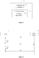
Figure 6 is a schematic diagram of signaling interactions in a typical application scenario according to an embodiment. Referring toFigure 6 , after aUE 1 resides in abase station 2 in the network, thebase station 2 may first perform an operation s1, in which a DRX configuration information is sent to theUE 1. - Secondly, the
UE 1 performs an operation s2, in which after receiving the DRX configuration information, a MAC entity may allocate SR configurations, where each SR configuration is allocated a sr-Response-RTT-Timer. - Thirdly, the
UE 1 performs an operation s3, in which an SR for an uplink data to be transmitted is generated and the SR is sent to thebase station 2. Accordingly, theUE 1 starts the sr-Response-RTT-Timer, and while the sr-Response -During RTT-Timer is running, theUE 1 may try to exit the active state. - Thereafter, when the sr-Response-RTT-Timer expires and the SR is pending, the
UE 1 may perform an operation s4, in which theUE 1 enters the active state and expects to receive the UL grant in response to the SR. - Further, the
base station 2 may perform an operation s5, in which thebase station 2 sends a UL grant to theUE 1, so that theUE 1 can send the uplink data to be transmitted. - Principles, detailed implementation and advantages of the
UE 1 and thebase station 2 in the application scenario shown inFigure 6 can be found in the above descriptions of the methods as shown inFigures 2 and3 , and are not described here. - In an embodiment of the present disclosure, a storage medium having computer instructions stored therein is provided, wherein once the computer instructions are executed, the above methods for controlling and indicating discontinuous reception of a UE as shown in
Figures 2 and3 are performed. The storage medium may be a computer readable storage medium, for example, a non-volatile or non-transitory memory. The computer-readable storage medium may include a Read Only Memory (ROM), a Random Access Memory (RAM), a magnetic disk, an optical disk or the like. - In an embodiment of the present disclosure, a terminal including a memory and a processor is provided, wherein the memory has computer instructions stored therein, and when the processor executes the computer instructions, the above method for controlling discontinuous reception of a UE as shown in
Figure 2 is performed. Optionally, the terminal may be a user equipment, for example, a NR UE. - In an embodiment of the present disclosure, a base station including a memory and a processor is provided, wherein the memory has computer instructions stored therein, and when the processor executes the computer instructions, the above method for indicating discontinuous reception of a UE as shown in
Figure 3 is performed. Optionally, the base station may be a satellite base station, for example, an NR base station installed on a satellite. - Although the present disclosure has been disclosed above with reference to preferred embodiments thereof, it should be understood that the disclosure is presented by way of example only, and not limitation. Those skilled in the art can modify and vary the embodiments without departing from the spirit and scope of the present disclosure.
Claims (15)
- A method for controlling discontinuous reception (DRX) of a user equipment (UE), comprising:determining a shortest duration from a media access control (MAC) entity sending a scheduling request (SR) to expecting an uplink grant (UP grant) in response to the SR; andallocating an sr-Response-Round Trip Time-Timer (sr-Response-RTT-Timer) for the SR, wherein a timing of the sr-Response-RTT-Timer is equal to the shortest duration, and the UE attempts to exit an active state while the sr-Response-RTT-Timer is running.
- The method according to claim 1, further comprising:
if the UE is configured with DRX and the SR is sent through a Physical Uplink Control Channel (PUCCH), starting the sr-Response-RTT-Timer of the SR when sending the SR through the PUCCH. - The method according to claim 2, wherein starting the sr-Response-RTT-Timer of the SR comprises:
configuring the MAC entity to start the sr-Response-RTT-Timer of the SR in a first symbol after the UE transmits the SR through the PUCCH. - The method according to claim 1, wherein before allocating the sr-Response-RTT-Timer for the SR, the method further comprises:
receiving a DRX configuration information, wherein the DRX configuration information comprises a configuration information of the sr-Response-RTT-Timer of the SR. - The method according to claim 4, wherein receiving the DRX configuration information sent by the network comprises:
receiving the DRX configuration information sent by the network through a Radio Resource Control (RRC) signaling. - The method according to any one of claims 1 to 5, wherein when the MAC entity sends the SR through the PUCCH, active periods of a DRX cycle at least comprises:
a period during which the sr-Response-RTT-Timer of the SR expires and the SR is pending. - The method according to any one of claims 1 to 5, wherein attempting to exit the active state while the sr-Response-RTT-Timer is running means that the UE exits the active state while the sr-Response-RTT-Timer is running and no other conditions that keep the UE in the active state are met.
- A method for indicating discontinuous reception (DRX) of a user equipment (UE), comprising:determining a DRX configuration information, wherein the DRX configuration information comprises a configuration information of an sr-Response-Round Trip Time-Timer (sr-Response-RTT-Timer) corresponding to a scheduling request (SR), and a timing of the sr-Response-RTT-Timer is equal to a shortest duration for a media access control (MAC) entity of the UE expecting an uplink grant (UP grant) in response to the SR after the SR is sent; andsending the DRX configuration information to the UE, so that the UE allocates the sr-Response-RTT-Timer for the SR according to the DRX configuration information and attempts to exit an active state while the sr-Response-RTT-Timer is running.
- The method according to claim 8, wherein sending the DRX configuration information to the UE comprises:
sending the DRX configuration information to the UE through a Radio Resource Control (RRC) signaling. - The method according to claim 8 or 9, wherein attempting to exit the active state while the sr-Response-RTT-Timer is running means that the UE exits the active state while the sr-Response-RTT-Timer is running and no other conditions that keep the UE in the active state are met.
- A device for controlling discontinuous reception (DRX) of a user equipment (UE), comprising:a determining module, adapted to determine a shortest duration from a media access control (MAC) entity sending a SR to expecting an uplink grant (UP grant) in response to the SR; andan allocating module, adapted to allocate an sr-Response-Round Trip Time-Timer (sr-Response-RTT-Timer) for the SR, wherein a timing of the sr-Response-RTT-Timer is equal to the shortest duration, and the UE attempts to exit an active state while the sr-Response-RTT-Timer is running.
- A device for indicating discontinuous reception (DRX) of a user equipment (UE), comprising:a determining module, adapted to determine a DRX configuration information, wherein the DRX configuration information includes a configuration information of an sr-Response-Round Trip Time-Timer (sr-Response-RTT-Timer), and a timing of the sr-Response-RTT-Timer is equal to a shortest duration for a media access control (MAC) entity of a UE expecting an uplink grant (UP grant) in response to an SR; anda sending module, adapted to send the DRX configuration information to the UE, so that the UE allocates the sr-Response-RTT-Timer for the SR according to the DRX configuration information and attempts to exit an active state while the sr-Response-RTT-Timer is running.
- A storage medium having computer instructions stored therein, wherein once the computer instructions are executed, the method for controlling discontinuous reception of a user equipment according to any one of claims 1 to 6 or the method for indicating discontinuous reception of a user equipment according to any one of claims 8 to 10 is performed.
- A terminal having a memory and a processor is provided, wherein the memory has computer instructions stored therein, and when the processor executes the computer instructions, the method for controlling discontinuous reception of a user equipment according to any one of claims 1 to 6 is performed.
- A base station having a memory and a processor is provided, wherein the memory has computer instructions stored therein, and when the processor executes the computer instructions, the method for indicating discontinuous reception of a user equipment according to any one of claims 8 to 10 is performed.
Applications Claiming Priority (2)
| Application Number | Priority Date | Filing Date | Title |
|---|---|---|---|
| CN201811009517.1A CN110876177B (en) | 2018-08-31 | 2018-08-31 | Control and indication method and device for UE discontinuous reception, storage medium, terminal, base station |
| PCT/CN2019/096788 WO2020042825A1 (en) | 2018-08-31 | 2019-07-19 | Method and device for controlling and indicating discontinuous reception of ue, storage medium, terminal and base station |
Publications (2)
| Publication Number | Publication Date |
|---|---|
| EP3846548A1 true EP3846548A1 (en) | 2021-07-07 |
| EP3846548A4 EP3846548A4 (en) | 2022-04-27 |
Family
ID=69644730
Family Applications (1)
| Application Number | Title | Priority Date | Filing Date |
|---|---|---|---|
| EP19853771.4A Withdrawn EP3846548A4 (en) | 2018-08-31 | 2019-07-19 | METHOD AND DEVICE FOR CONTROLLING AND INDICATING DISCONTINUOUS RECEIPT OF USER EQUIPMENT, STORAGE MEDIA, TERMINAL AND BASE STATION ASSOCIATED |
Country Status (6)
| Country | Link |
|---|---|
| US (1) | US20210329731A1 (en) |
| EP (1) | EP3846548A4 (en) |
| JP (1) | JP7231711B2 (en) |
| KR (1) | KR102455013B1 (en) |
| CN (1) | CN110876177B (en) |
| WO (1) | WO2020042825A1 (en) |
Cited By (1)
| Publication number | Priority date | Publication date | Assignee | Title |
|---|---|---|---|---|
| EP4203562A4 (en) * | 2020-09-09 | 2024-03-13 | Sony Group Corporation | ELECTRONIC DEVICE, WIRELESS COMMUNICATION METHOD AND COMPUTER READABLE STORAGE MEDIUM |
Families Citing this family (15)
| Publication number | Priority date | Publication date | Assignee | Title |
|---|---|---|---|---|
| WO2020071698A1 (en) * | 2018-10-05 | 2020-04-09 | 주식회사 케이티 | Method for performing communication by using non-terrestrial network and apparatus thereof |
| KR102557924B1 (en) * | 2019-03-29 | 2023-07-20 | 엘지전자 주식회사 | Physical downlink control channel monitoring in wireless communication system |
| CA3190413A1 (en) * | 2019-10-03 | 2021-04-08 | Ofinno, Llc | Discontinuous reception for a two-step random access procedure |
| US20210258105A1 (en) * | 2020-02-13 | 2021-08-19 | Qualcomm Incorporated | Discontinuous reception in a network |
| US11736975B2 (en) * | 2020-05-15 | 2023-08-22 | Qualcomm Incorporated | Buffer status report transmissions in non-terrestrial networks |
| WO2021248450A1 (en) * | 2020-06-12 | 2021-12-16 | Lenovo (Beijing) Limited | Method and apparatus for sidelink drx operation |
| WO2022120747A1 (en) * | 2020-12-10 | 2022-06-16 | Oppo广东移动通信有限公司 | Wireless communication method and terminal device |
| CN116472749A (en) * | 2020-12-21 | 2023-07-21 | Oppo广东移动通信有限公司 | Wireless communication method and terminal device |
| WO2022141596A1 (en) * | 2020-12-31 | 2022-07-07 | 北京小米移动软件有限公司 | Receiving control method and device |
| WO2022160137A1 (en) * | 2021-01-27 | 2022-08-04 | Oppo广东移动通信有限公司 | Wireless communication method, terminal device and network device |
| CN115150974B (en) * | 2021-03-29 | 2024-12-17 | 大唐移动通信设备有限公司 | Direct communication interface DRX and/or DTX state maintenance method and direct communication terminal |
| CA3154798A1 (en) * | 2021-03-31 | 2022-09-30 | Comcast Cable Communications, Llc | Random access associated with buffer status reporting |
| CN115623562B (en) * | 2021-07-14 | 2025-10-14 | 展讯通信(上海)有限公司 | Scheduling method, device, equipment, medium and chip |
| WO2023093815A1 (en) * | 2021-11-25 | 2023-06-01 | Mediatek Singapore Pte. Ltd. | Method and apparatus for enhanced discontinuous reception configuration in mobile communications |
| US20240205912A1 (en) * | 2022-12-20 | 2024-06-20 | Qualcomm Incorporated | Sidelink feedback for network energy savings |
Family Cites Families (10)
| Publication number | Priority date | Publication date | Assignee | Title |
|---|---|---|---|---|
| EP3002881B2 (en) * | 2008-02-01 | 2022-08-03 | Guangdong Oppo Mobile Telecommunications Corp., Ltd. | System and method for uplink timing synchronization in conjunction with discontinuous reception |
| US9161371B2 (en) * | 2011-07-21 | 2015-10-13 | Qualcomm Incorporated | Power optimization using scheduling request delay |
| ES2682321T3 (en) * | 2012-07-09 | 2018-09-20 | Lg Electronics Inc. | Method and apparatus for controlling uplink transmission in discontinuous reception operation in wireless communication system |
| WO2014035074A1 (en) * | 2012-08-27 | 2014-03-06 | Lg Electronics Inc. | Method and apparatus for configuring a discontinuous reception (drx) operation in a wireless communication system |
| US9497771B2 (en) * | 2014-04-18 | 2016-11-15 | Apple Inc. | Deterministic RRC connections |
| US20170034781A1 (en) * | 2015-07-30 | 2017-02-02 | Samsung Electronics Co., Ltd. | Method of enhancing uplink transmission handling in a discontinuous reception (drx) mode of a user equipment |
| US10009923B2 (en) * | 2016-01-28 | 2018-06-26 | Qualcomm Incorporated | Contention-based data transmissions on return link |
| CN107155212B (en) * | 2016-03-03 | 2021-07-30 | 中兴通讯股份有限公司 | Discontinuous reception control method and device |
| CN106255184B (en) * | 2016-07-28 | 2019-10-25 | 华为技术有限公司 | A data transmission method and terminal equipment |
| US20180124701A1 (en) * | 2016-10-31 | 2018-05-03 | Mediatek Inc. | Scheduling request (sr) period extension for low power enhancement in a wireless communication device |
-
2018
- 2018-08-31 CN CN201811009517.1A patent/CN110876177B/en active Active
-
2019
- 2019-07-19 KR KR1020217008315A patent/KR102455013B1/en active Active
- 2019-07-19 WO PCT/CN2019/096788 patent/WO2020042825A1/en not_active Ceased
- 2019-07-19 JP JP2021510332A patent/JP7231711B2/en active Active
- 2019-07-19 EP EP19853771.4A patent/EP3846548A4/en not_active Withdrawn
- 2019-07-19 US US17/271,238 patent/US20210329731A1/en not_active Abandoned
Cited By (1)
| Publication number | Priority date | Publication date | Assignee | Title |
|---|---|---|---|---|
| EP4203562A4 (en) * | 2020-09-09 | 2024-03-13 | Sony Group Corporation | ELECTRONIC DEVICE, WIRELESS COMMUNICATION METHOD AND COMPUTER READABLE STORAGE MEDIUM |
Also Published As
| Publication number | Publication date |
|---|---|
| EP3846548A4 (en) | 2022-04-27 |
| WO2020042825A1 (en) | 2020-03-05 |
| KR20210047902A (en) | 2021-04-30 |
| US20210329731A1 (en) | 2021-10-21 |
| CN110876177A (en) | 2020-03-10 |
| JP2021536180A (en) | 2021-12-23 |
| CN110876177B (en) | 2021-09-07 |
| KR102455013B1 (en) | 2022-10-13 |
| JP7231711B2 (en) | 2023-03-01 |
Similar Documents
| Publication | Publication Date | Title |
|---|---|---|
| KR102455013B1 (en) | Method and apparatus for controlling and instructing discontinuous reception of UE, storage medium, terminal and base station | |
| US20220174747A1 (en) | Method and apparatus for improving msg3 transmission of random access procedure in a wireless communication system | |
| US12309769B2 (en) | Discontinuous reception method, terminal device and storage medium | |
| CN110035502B (en) | Communication method, communication device and network device | |
| EP3927053B1 (en) | Method, terminal storage medium for operating a drx timer | |
| CN115486188B (en) | Buffer status report transmission in non-terrestrial networks | |
| US12048051B2 (en) | Method and apparatus for data transmission, terminal, and storage medium | |
| CN110876210B (en) | Control method and device for UE discontinuous reception, storage medium and terminal | |
| CN115209561B (en) | Method and apparatus for processing contention resolution in a wireless communication system | |
| US10491420B2 (en) | Method, terminal, and base station for asynchronous uplink transmission | |
| JP2015501623A (en) | Various timer operations in wireless communication systems | |
| US12052665B2 (en) | Methods and apparatuses for using power-saving signal pattern, device and system | |
| US20250063385A1 (en) | Method and apparatus for reporting information, device, and storage medium | |
| US20240014890A1 (en) | Methods, communications device and base station for a non-terrestrial network | |
| CN114650563A (en) | Method and apparatus for using buffer status report enhancement in a wireless communication system | |
| CN116530160B (en) | Methods for terminal devices to switch Search Space Set (SSSG) packets, terminal devices, and network devices. | |
| CN115868132B (en) | Wireless communication method and device | |
| US20260122690A1 (en) | A method for performing random access between a user equipment and a network node in a wireless communication network | |
| JP2023536002A (en) | Method and apparatus for data transmission | |
| US20260020046A1 (en) | Method and apparatus of handling bwp switching command based on ue type | |
| WO2026020390A1 (en) | Wireless communication method and apparatus, and device and storage medium | |
| WO2024231563A1 (en) | Enhanced cell dtx/drx |
Legal Events
| Date | Code | Title | Description |
|---|---|---|---|
| STAA | Information on the status of an ep patent application or granted ep patent |
Free format text: STATUS: THE INTERNATIONAL PUBLICATION HAS BEEN MADE |
|
| STAA | Information on the status of an ep patent application or granted ep patent |
Free format text: STATUS: REQUEST FOR EXAMINATION WAS MADE |
|
| PUAI | Public reference made under article 153(3) epc to a published international application that has entered the european phase |
Free format text: ORIGINAL CODE: 0009012 |
|
| 17P | Request for examination filed |
Effective date: 20210209 |
|
| AK | Designated contracting states |
Kind code of ref document: A1 Designated state(s): AL AT BE BG CH CY CZ DE DK EE ES FI FR GB GR HR HU IE IS IT LI LT LU LV MC MK MT NL NO PL PT RO RS SE SI SK SM TR |
|
| DAV | Request for validation of the european patent (deleted) | ||
| DAX | Request for extension of the european patent (deleted) | ||
| A4 | Supplementary search report drawn up and despatched |
Effective date: 20220329 |
|
| RIC1 | Information provided on ipc code assigned before grant |
Ipc: H04W 84/06 20090101ALI20220323BHEP Ipc: H04W 76/28 20180101ALI20220323BHEP Ipc: H04L 43/0864 20220101ALI20220323BHEP Ipc: H04W 52/02 20090101AFI20220323BHEP |
|
| STAA | Information on the status of an ep patent application or granted ep patent |
Free format text: STATUS: EXAMINATION IS IN PROGRESS |
|
| 17Q | First examination report despatched |
Effective date: 20230512 |
|
| STAA | Information on the status of an ep patent application or granted ep patent |
Free format text: STATUS: THE APPLICATION IS DEEMED TO BE WITHDRAWN |
|
| 18D | Application deemed to be withdrawn |
Effective date: 20240924 |