EP3846436A1 - Resilient housing - Google Patents
Resilient housing Download PDFInfo
- Publication number
- EP3846436A1 EP3846436A1 EP20214782.3A EP20214782A EP3846436A1 EP 3846436 A1 EP3846436 A1 EP 3846436A1 EP 20214782 A EP20214782 A EP 20214782A EP 3846436 A1 EP3846436 A1 EP 3846436A1
- Authority
- EP
- European Patent Office
- Prior art keywords
- resilient housing
- axis
- retention features
- disposed
- resilient
- Prior art date
- Legal status (The legal status is an assumption and is not a legal conclusion. Google has not performed a legal analysis and makes no representation as to the accuracy of the status listed.)
- Withdrawn
Links
Images




Classifications
-
- F—MECHANICAL ENGINEERING; LIGHTING; HEATING; WEAPONS; BLASTING
- F25—REFRIGERATION OR COOLING; COMBINED HEATING AND REFRIGERATION SYSTEMS; HEAT PUMP SYSTEMS; MANUFACTURE OR STORAGE OF ICE; LIQUEFACTION SOLIDIFICATION OF GASES
- F25D—REFRIGERATORS; COLD ROOMS; ICE-BOXES; COOLING OR FREEZING APPARATUS NOT OTHERWISE PROVIDED FOR
- F25D29/00—Arrangement or mounting of control or safety devices
- F25D29/005—Mounting of control devices
-
- G—PHYSICS
- G06—COMPUTING OR CALCULATING; COUNTING
- G06F—ELECTRIC DIGITAL DATA PROCESSING
- G06F1/00—Details not covered by groups G06F3/00 - G06F13/00 and G06F21/00
- G06F1/16—Constructional details or arrangements
- G06F1/1613—Constructional details or arrangements for portable computers
- G06F1/1633—Constructional details or arrangements of portable computers not specific to the type of enclosures covered by groups G06F1/1615 - G06F1/1626
- G06F1/1684—Constructional details or arrangements related to integrated I/O peripherals not covered by groups G06F1/1635 - G06F1/1675
- G06F1/1686—Constructional details or arrangements related to integrated I/O peripherals not covered by groups G06F1/1635 - G06F1/1675 the I/O peripheral being an integrated camera
-
- G—PHYSICS
- G03—PHOTOGRAPHY; CINEMATOGRAPHY; ANALOGOUS TECHNIQUES USING WAVES OTHER THAN OPTICAL WAVES; ELECTROGRAPHY; HOLOGRAPHY
- G03B—APPARATUS OR ARRANGEMENTS FOR TAKING PHOTOGRAPHS OR FOR PROJECTING OR VIEWING THEM; APPARATUS OR ARRANGEMENTS EMPLOYING ANALOGOUS TECHNIQUES USING WAVES OTHER THAN OPTICAL WAVES; ACCESSORIES THEREFOR
- G03B17/00—Details of cameras or camera bodies; Accessories therefor
- G03B17/56—Accessories
- G03B17/561—Support related camera accessories
-
- G—PHYSICS
- G03—PHOTOGRAPHY; CINEMATOGRAPHY; ANALOGOUS TECHNIQUES USING WAVES OTHER THAN OPTICAL WAVES; ELECTROGRAPHY; HOLOGRAPHY
- G03B—APPARATUS OR ARRANGEMENTS FOR TAKING PHOTOGRAPHS OR FOR PROJECTING OR VIEWING THEM; APPARATUS OR ARRANGEMENTS EMPLOYING ANALOGOUS TECHNIQUES USING WAVES OTHER THAN OPTICAL WAVES; ACCESSORIES THEREFOR
- G03B29/00—Combinations of cameras, projectors or photographic printing apparatus with non-photographic non-optical apparatus, e.g. clocks or weapons; Cameras having the shape of other objects
-
- G—PHYSICS
- G06—COMPUTING OR CALCULATING; COUNTING
- G06F—ELECTRIC DIGITAL DATA PROCESSING
- G06F1/00—Details not covered by groups G06F3/00 - G06F13/00 and G06F21/00
- G06F1/16—Constructional details or arrangements
- G06F1/18—Packaging or power distribution
- G06F1/181—Enclosures
-
- H—ELECTRICITY
- H04—ELECTRIC COMMUNICATION TECHNIQUE
- H04N—PICTORIAL COMMUNICATION, e.g. TELEVISION
- H04N23/00—Cameras or camera modules comprising electronic image sensors; Control thereof
- H04N23/50—Constructional details
-
- H—ELECTRICITY
- H04—ELECTRIC COMMUNICATION TECHNIQUE
- H04N—PICTORIAL COMMUNICATION, e.g. TELEVISION
- H04N23/00—Cameras or camera modules comprising electronic image sensors; Control thereof
- H04N23/50—Constructional details
- H04N23/51—Housings
-
- H—ELECTRICITY
- H04—ELECTRIC COMMUNICATION TECHNIQUE
- H04N—PICTORIAL COMMUNICATION, e.g. TELEVISION
- H04N23/00—Cameras or camera modules comprising electronic image sensors; Control thereof
- H04N23/57—Mechanical or electrical details of cameras or camera modules specially adapted for being embedded in other devices
-
- F—MECHANICAL ENGINEERING; LIGHTING; HEATING; WEAPONS; BLASTING
- F25—REFRIGERATION OR COOLING; COMBINED HEATING AND REFRIGERATION SYSTEMS; HEAT PUMP SYSTEMS; MANUFACTURE OR STORAGE OF ICE; LIQUEFACTION SOLIDIFICATION OF GASES
- F25D—REFRIGERATORS; COLD ROOMS; ICE-BOXES; COOLING OR FREEZING APPARATUS NOT OTHERWISE PROVIDED FOR
- F25D2500/00—Problems to be solved
- F25D2500/06—Stock management
-
- F—MECHANICAL ENGINEERING; LIGHTING; HEATING; WEAPONS; BLASTING
- F25—REFRIGERATION OR COOLING; COMBINED HEATING AND REFRIGERATION SYSTEMS; HEAT PUMP SYSTEMS; MANUFACTURE OR STORAGE OF ICE; LIQUEFACTION SOLIDIFICATION OF GASES
- F25D—REFRIGERATORS; COLD ROOMS; ICE-BOXES; COOLING OR FREEZING APPARATUS NOT OTHERWISE PROVIDED FOR
- F25D2700/00—Means for sensing or measuring; Sensors therefor
- F25D2700/06—Sensors detecting the presence of a product
Definitions
- the present disclosure generally relates to a housing for a data collection device, and more specifically, to a resilient housing for a data collection device.
- a monitoring system for an appliance includes a resilient housing that has a first end and a second end.
- the resilient housing includes retention features, and a body that has a rear attachment surface and a support surface.
- the body also includes first and second elongated walls and first and second end walls that cooperate to define the support surface.
- the resilient housing further includes a coupling layer that is disposed on the rear attachment surface of the body, and a data collection device that is disposed on the support surface of the body and is operably coupled to the resilient housing via the retention features.
- a monitoring assembly for an appliance includes a resilient housing including a plurality of retention features and a body that extend between the plurality of retention features.
- the body has a rear attachment surface and a support surface that is defined between the plurality of retention features.
- a data collection device is disposed on the support surface of the body and is operably coupled to the body of the resilient housing via the plurality of retention features.
- a coupling layer is disposed on the rear attachment surface of the body.
- a resilient housing for a monitoring system includes a plurality of retention features, and a body that has a first end and a second end and extends between the plurality of retention features.
- the body includes a support surface that is defined between the plurality of retention features by elongated walls and end walls and a rear attachment surface.
- a resilient housing for a monitoring system further includes a coupling layer that is disposed on the rear attachment surface of the body.
- the present illustrated embodiments reside primarily in combinations of apparatus components related to a resilient housing for a camera. Accordingly, the apparatus components have been represented, where appropriate, by conventional symbols in the drawings, showing only those specific details that are pertinent to understanding the embodiments of the present disclosure so as not to obscure the disclosure with details that will be readily apparent to those of ordinary skill in the art having the benefit of the description herein. Further, like numerals in the description and drawings represent like elements.
- the terms “upper,” “lower,” “right,” “left,” “rear,” “front,” “vertical,” “horizontal,” and derivatives thereof shall relate to the disclosure as oriented in FIG. 1 .
- the term “front” shall refer to the surface of the element closer to an intended viewer, and the term “rear” shall refer to the surface of the element further from the intended viewer.
- the disclosure may assume various alternative orientations, except where expressly specified to the contrary.
- the specific devices and processes illustrated in the attached drawings, and described in the following specification are simply exemplary embodiments of the inventive concepts defined in the appended claims. Hence, specific dimensions and other physical characteristics relating to the embodiments disclosed herein are not to be considered as limiting, unless the claims expressly state otherwise.
- reference numeral 10 generally designates a monitoring system for an appliance 12 that includes a resilient housing 14 having a first end 16 and a second end 18.
- the resilient housing 14 includes retention features 20 and a body 22 that has a rear attachment surface 24 and a support surface 26.
- the body 22 also includes first and second elongated walls 28, 30 and first and second end walls 32, 34 that cooperate to define the support surface 26.
- a coupling layer 36 is disposed on the rear attachment surface 24 of the body 22, and a data collection device 38 is disposed on the support surface 26 of the body 22.
- the data collection device 38 is operably coupled to the resilient housing 14 via the retention features 20.
- the resilient housing 14 is illustrated within the appliance 12.
- the appliance 12 is illustrated as a French-door style refrigerator with a bottom-mounted drawer 44 and first and second doors 48, 52.
- the resilient housing 14 may be used in other appliances, as well as other cabinetry, pantries, and similar storage compartments.
- Storage bins 56, drawers 60, and shelves 64 may be coupled to an interior surface 68 of the appliance 12, and each is configured to support and store consumer items typically stored in the appliance 12.
- a user may repeatedly open and close the doors 48, 52 to gauge the need to replenish items stored within the conventional refrigerator. For example, the consumer may repeatedly check the contents of the conventional refrigerator for purposes of assembling a grocery list or determine ingredients needed for a recipe.
- the monitoring system 10 may also be referred to as a monitoring assembly. As illustrated in FIGS. 1 and 2 , the monitoring system 10 is positioned on a rear wall 74 of the appliance 12. It is also contemplated that the monitoring system 10 can be positioned in any location within the appliance 12 to maximize the images and views within the appliance 12. Additionally or alternatively, a plurality of monitoring systems 10 may be coupled within the appliance 12 and communicatively coupled, such that a variety of images are communicated between the monitoring system 10 and, ultimately, to the user.
- the monitoring system 10 is communicatively coupled to a controller 76 that receives the images from the data collection device 38.
- the data collection device 38 may include a variety of devices, such as data sensors, configured to collect various data within the appliance 12.
- the data collection device 38 described herein is an imager.
- the imager 38 is retained within the resilient housing 14, and the resilient housing 14 is operably coupled to the interior surface 68 of the appliance 12. It is generally contemplated that the imager 38 may be a camera or other vision-based device configured to capture image data of an interior 84 of the appliance 12.
- the imager 38 includes a lens 90 and a curved surface 94 disposed around the lens 90 in which a sensor 96 can be disposed to sense the amount of light present within the appliance 12.
- the lens 90, the curved surface 94, and the sensor 96 are generally disposed within an angular casing 98, described below.
- the imager 38 may collect data when the light present in the appliance 12 reaches a particular visible or non-visible illumination level.
- the imager 38 may be triggered by a motion sensor that detects movement of the door, or a proximity sensor that detects movement within a close range of the proximity sensor.
- the consumer typically opens the doors 48, 52 prior to data being collected by the imager 38.
- the imager 38 can utilize the light generated by the appliance 12 in addition to the natural light that may enter the appliance 12 with the doors 48, 52 open.
- movement of the controller 76 activates the imager 38 to capture an image.
- the angular casing 98 is movable about an axis to capture a multitude of images of the interior 84 of the appliance 12. It is also contemplated that the angular casing 98 may be fixed in a position, such that the imager 38 is focused on a single section of the appliance 12.
- Conventional systems may utilize a rigid structure that adheres to a side of a conventional appliance.
- the conventional systems may be difficult to remove from the conventional appliance. Accordingly, the residue of the adhesives used to bond the conventional system to the side of the conventional appliance may remain on the conventional appliance after attempted removal.
- the retention features 20 operably couple the imager 38 within the resilient housing 14.
- the retention features 20 may be referred to as a plurality of retention features 20 and each have a semi-circular construction to generally cradle the imager 38 within the resilient housing 14 against the support surface 26.
- the retention features 20 as illustrated in FIGS. 3 and 4 include a retention feature 20 at each corner of the resilient housing 14.
- the first end 16 and the second end 18 of the resilient housing 14 each include a first retention feature 110 and a second retention feature 112.
- the first and second retention features 110, 112 cooperate to retain the imager 38 within the resilient housing 14 and are described in more detail below.
- the support surface 26 of the body 22 abuts a rear surface 114 of the imager 38 to further support the imager 38 within the resilient housing 14. Additionally or alternatively, the support surface 26 of the resilient housing 14 may provide a structural backing to the imager 38, such that the rear surface 114 of the imager 38 may be integral with the support surface 26. It is generally contemplated that to remove the resilient housing 14 from the interior surface 68 of the appliance 12, the imager 38 is first removed from the resilient housing 14 as the imager 38 is typically a rigid body. The rigidity of a body, such as the imager 38, can make removal of the monitoring system 10 more difficult.
- the resilient housing 14 is formed from a generally pliable material and is contemplated to be generally flexible about a y-axis Y and generally rigid about an x-axis X, described in more detail below.
- the resilient housing 14 is selectively coupled to the interior surface 68 of the appliance 12.
- the coupling layer 36 that is disposed on the rear attachment surface 24 of the resilient housing 14 can be securely, but removably, coupled to the interior surface 68 of the appliance 12.
- the coupling layer 36 includes first and second surfaces 116, 118, wherein the first surface 116 is coupled to the rear attachment surface 24 of the body 22.
- the first surface 116 is a standard adhesive material that securely adheres the coupling layer 36 to the rear attachment surface 24, while the second surface 118 can be a micro-suction adhesive configured to be removable from a mounting surface to which the second surface 118 is coupled.
- the second surface 118 formed from the micro-suction adhesive, has a plurality of nano-cavities 120 disposed along the second surface 118.
- Each of the nano-cavities 120 contains air, which is removed from the nano-cavities 120 upon compression of the second surface 118.
- the compression of the nano-cavities 120 activates the micro-suction adhesive to seal against, for example, the interior surface 68 of the appliance 12.
- This adherence defines a partial vacuum between the interior surface 68 and the coupling layer 36 and, as a result, the resilient housing 14.
- this coupling layer 36 may be used on a resilient housing 14 of various sizes, such that the level of force applied to evacuate the nano-cavities 120 proportionally increases with the size of the resilient housing 14.
- the amount of pressure exerted against the coupling layer 36 to evacuate the nano-cavities 120 may inform the degree of attachment of the resilient housing 14 to the interior surface 68 of the appliance 12.
- the second surface 118 of the coupling layer 36 may include a traditional adhesive generally known in the art.
- the traditional adhesive may be similar to the standard adhesive material used on the first surface 116 or may be a different traditional adhesive known in the art.
- the traditional adhesive may fix the resilient housing 14 to the interior surface 68 of the appliance 12. Additionally or alternatively, the traditional adhesive may allow the resilient housing 14 to be selectively removed from and readjusted relative to the interior surface 68.
- the coupling layer 36 primarily discussed in the present disclosure is one that allows the selective removal of the resilient housing 14 from the interior surface 68 whether using the micro-suction adhesive or the traditional adhesive.
- the imager 38 is removably coupled to the support surface 26 via the retention features 20 to aid the removal and/or adjustment of the resilient housing 14.
- the first and second elongated walls 28, 30 and the first and second end walls 32, 34 of the body 22, in addition to the retention features 20, are configured to support the imager 38 within the resilient housing 14.
- the first and second elongated walls 28, 30 extend between the first retention features 110 on the first and second ends 16, 18 of the resilient housing 14.
- the first and second end walls 32, 34 extend between the first and second retention features 110, 112 on each of the first and second ends 16, 18, respectively.
- the first end wall 32 is defined on the first end 16 of the resilient housing 14, and the second end wall 34 is defined on the second end 18 of the resilient housing 14.
- first retention feature 110 and the second retention feature 112 illustrated in FIG. 7 are disposed on the first end 16 and the second end 18, respectively. It is further contemplated that the retention features 20 may be configured to be inserted into the imager 38.
- the retention features 20 may be posts that extend through the imager 38 so the resilient housing 14 defines a backing of the imager 38. In any one of the above constructions, the imager 38 is removably coupled to the resilient housing 14 via the retention features 20.
- the elongated walls 28, 30 have a thickness T 1 and the end walls 32, 34 have a thickness T 2 .
- the thickness T 2 of the end walls 32, 34 is greater than the thickness T 1 of the elongated walls 28, 30. It is contemplated that the thickness T 2 of the end walls 32, 34 provide the body 22 with additional structural support to retain the imager 38 on the support surface 26.
- the lesser thickness T 1 of the elongated walls 28, 30, in relation to the greater thickness T 2 of the end walls 32, 34 maintains the overall resiliency and flexibility of the resilient housing 14.
- the thickness T 2 can help minimize rotation of the resilient housing 14 about the x-axis X, while the thickness T 1 of the elongated walls 28, 30 promotes the flexibility of the resilient housing 14 about the y-axis Y.
- the assembled monitoring system 10 may have an increased weight as compared to the resilient housing 14 alone due to the weight of the imager 38, which increases the load L 1 placed upon the coupling layer 36.
- gravitational force G will result in a peel-force P x acting upon the resilient housing 14, which will affect the adherence of the monitoring system 10 to the interior surface 68 of the appliance 12.
- the resilient housing 14 is highly resistant to the peel-force P x about the x-axis X, which minimizes the potential of peeling from the interior surface 68 ( FIG. 2 ) under gravitational force G.
- the body 22 of the resilient housing 14 may be additionally braced with reinforcement ribs 130 disposed along a length L 2 of the body 22.
- the reinforcement ribs 130 increase the general rigidity of the body 22 of the resilient housing 14.
- the body 22 is less likely to bend about the x-axis X as a result of the increased rigidity with the reinforcement ribs 130.
- the reinforcement ribs 130 extend perpendicular to the x-axis X of the body 22 to resist peeling about the x-axis X.
- the x-axis X may be defined as extending between a central location 132 of the first and second end walls 32, 34 of the resilient housing 14.
- the reinforcement ribs 130 are perpendicular to the x-axis X, the reinforcement ribs 130 are accordingly parallel along the y-axis Y to allow bending and flexing of the resilient housing 14 relative to the y-axis Y.
- the y-axis Y is defined parallel to the first and second end walls 32, 34 of the body 22 and the reinforcement ribs 130.
- the resilient housing 14 has a greater ability to bend, flex, and be removed along the y-axis Y, the insertion of the imager 38 within the retention features 20 of the resilient housing 14 minimizes the potential of bending and removal of the monitoring system 10 from the interior surface 68 of the appliance 12.
- first and second retention features 110, 112 have a generally semi-circular cross-section configured to cradle the imager 38.
- the body 22 of the resilient housing 14 is free from both the elongated walls 28, 30 and the end walls 32, 34 as the first and second retention features 110, 112 provide sufficient structural rigidity for the resilient housing 14 about the x-axis X.
- first and second retention features 110, 112 can generally replace the first and second end walls 32, 34 of the aspect depicted in FIG. 6 .
- first and second retention features 110, 112 may increase the rigidity of the resilient housing 14 to the extent that the body 22 of the resilient housing 14 can be free from the first and second elongated walls 28, 30.
- first and second retention features 110, 112 in FIG. 7 extend along a greater portion of the body 22 as compared to the retention features 20 in FIG. 6 .
- the aspect illustrated in FIG. 6 is described herein. However, it is also contemplated that the description described below also applies to the aspect as described with relation to FIG. 7 .
- the peel-force P y about the y-axis Y is typically much lower than the peel-force P x about the x-axis X as a result of the overall height H R and thickness T R of the resilient housing 14.
- the resilient housing 14 has a small cross-sectional area moment of inertia I A-A,y relative to the y-axis Y, such that the resistance to peeling about the y-axis Y is less than the resistance to peeling about the x-axis X.
- the resilient housing 14 In addition to the moment of inertia I A-A,y relative to the y-axis Y, the resilient housing 14 also has a cross-sectional area moment of inertia I B-B,x relative to the x-axis X, which for purposes of this disclosure is greater than the moment of inertia I A-A,y about the y-axis Y.
- the moments of inertia I A-A,y , I B-B,x are generally defined as a measure of the resilient housing's 14 resistance to rotation, such as peeling or bending, about the y-axis Y and the x-axis X, respectively.
- the user can easily peel and remove the resilient housing 14 from the interior surface 68 of the appliance 12 about the y-axis Y. Due to the relatively low resistance to peeling about the y-axis Y, the second surface 118 of the coupling layer 36 easily releases from the interior surface 68 of the appliance 12, and the interior surface 68 is free from the residue after the removal of the resilient housing 14.
- the bending of the resilient housing 14 about the y-axis Y is defined by the cross-sectional moment of inertia I A-A,y taken at point A-A.
- the moments of inertia I A-A,y , I B-B,x are based upon the integral of a distance z squared from the y-axis Y or the x-axis X, respectively, and multiplied by the differential area dA.
- the moment of inertia I A-A,y relative to the y-axis Y is proportional to the height H R of the resilient housing 14 and is also proportional to the thickness T R of the resilient housing 14 cubed.
- the height H R of the resilient housing 14 is determined to maximize the amount of the coupling layer 36 that will securely, but removably, couple the monitoring system 10 to the interior surface 68 of the appliance 12.
- the thickness T R of the body 22 is determined relative to the height H R of the resilient housing 14 to maintain the flexibility of the resilient housing 14 so the coupling layer 36 can be easily removed from the interior surface 68 of the appliance 12.
- the first and second elongated walls 28, 30 have a thickness T 1 that is less than a thickness T 2 of the first and second end walls 32, 34 to maximize the flexibility of the resilient housing 14.
- the moment of inertia I A-A,y about the y-axis Y is typically a measure of the efficiency of the cross-sectional shape of the resilient housing 14 to resist bending.
- the resilient housing 14 is configured to bend and flex about the y-axis Y, the moment of inertia I A-A,y is relatively small.
- the thickness T R of the resilient housing 14 is proportionally small, such that the thinner the resilient housing 14 the smaller the moment of inertia I A-A,y .
- the moment of inertia I B-B,x of a cross-sectional point B-B of the resilient housing 14 relative to the x-axis X is affected by, but not necessarily proportional to, the length L 2 of the resilient housing 14, the thickness T R of the resilient housing 14 cubed, and the thickness T 2 of the first and second end walls 32, 34.
- the moment of inertia I B-B,x about the x-axis X is generally larger than the moment of inertia I A-A,y about the y-axis Y of the resilient housing 14.
- the length L 2 of the resilient housing 14 is generally determined to maximize the amount of the coupling layer 36 attached to the rear attachment surface 24 of the resilient housing 14 while maintaining a large moment of inertia I B-B,x about the x-axis X.
- the thickness T R of the resilient housing 14 is determined to maximize the bending about the y-axis Y of the resilient housing 14 and minimize bending about the x-axis X for purposes of selectively coupling the resilient housing 14 to the appliance 12.
- the dimensions of the first and second end walls 32, 34 can be altered to increase the moment of inertia I B-B,x relative the x-axis X.
- the resilient housing 14 may resist bending about the x-axis X that may otherwise occur as a result of the gravitational force G acting upon the monitoring system 10.
- increasing a height of the retention features 20 and the first and second end walls 32, 34 may greatly increase on the moment of inertia I B-B,x about the x-axis X, such that the resilient housing 14 may resist bending about the x-axis X to a greater degree when the retention features 20 have a larger height.
- the reinforcement ribs 130 may be added to further increase the moment of inertia I B-B,x , and consequently decrease bending about the x-axis X.
- the reinforcement ribs 130 are disposed about the y-axis Y and, accordingly, provide further resistance to bending relative the x-axis X for the resilient housing 14 while flexion of the resilient housing 14 relative the y-axis Y is generally uninhibited.
- the monitoring system 10 may communicate with the user's portable computing device and/or other programmable software devices that may communicate with the monitoring system 10. Based on the shared information, the monitoring system 10 may update the user on the current status of items within the appliance 12. Accordingly, the user may receive current information on the items within the appliance 12 to inform the user during a process, such as shopping or ordering of items. In addition, the monitoring system 10 may communicate with the controller and the user's portable computing device to deliver recipe options based on the data collected by the monitoring system 10. To execute such functions, it is generally contemplated that the monitoring system 10 may be communicatively coupled to the controller that is connected to a network to send the information to the user's portable computing device or other software device.
- the relatively small moment of inertia relative the y-axis Y provides that the coupling layer 36 may be easily removed from the interior surface 68 of the appliance 12 while the interior surface 68 is free from residue after the removal of the resilient housing 14 from the appliance 12.
- the user may remove and replace the monitoring system 10 in various locations within the appliance 12 without excessive cleaning or abrasive measures to remove residue of the coupling layer 36 that may otherwise be on the interior surface 68 of the appliance 12 after the removal of the resilient housing 14.
- a monitoring system for an appliance includes a resilient housing that has a first end and a second end.
- the resilient housing includes retention features, and a body that has a rear attachment surface and a support surface.
- the body also includes first and second elongated walls and first and second end walls that cooperate to define the support surface.
- the resilient housing further includes a coupling layer that is disposed on the rear attachment surface of the body, and a data collection device that is disposed on the support surface of the body and is operably coupled to the resilient housing via the retention features.
- a data collection device is an imager that is configured to collect image data of an interior of said appliance.
- a resilient housing further includes a plurality of reinforcement ribs that are disposed along a support surface of a body.
- retention features include a first retention feature and a second retention feature.
- first and second retention features are disposed on both a first end and a second end of a resilient housing.
- a first retention feature is disposed on a first end of a resilient housing, and a second retention feature is disposed on a second end of the resilient housing.
- a body is configured to bend about a y-axis that is defined parallel to first and second retention features.
- a monitoring assembly for an appliance includes a resilient housing including a plurality of retention features and a body that extend between the plurality of retention features.
- the body has a rear attachment surface and a support surface that is defined between the plurality of retention features.
- a data collection device is disposed on the support surface of the body and is operably coupled to the body of the resilient housing via the plurality of retention features.
- a coupling layer is disposed on the rear attachment surface of the body.
- a resilient housing includes a first end and a second end.
- a plurality of retention features are disposed on the first and second ends of the resilient housing.
- a body of a resilient housing includes a first end wall and a second end wall.
- the first end wall is disposed on a first end of the resilient housing between a first retention feature and a second retention feature.
- a plurality of retention features includes a first retention feature and a second retention feature.
- the first retention feature is disposed on a first end of a resilient housing and the second retention feature is disposed on a second end of the resilient housing.
- a body includes a first elongated wall and a second elongated wall.
- a resilient housing for a monitoring system includes a plurality of retention features, and a body that has a first end and a second end and extends between the plurality of retention features.
- the body includes a support surface that is defined between the plurality of retention features by elongated walls and end walls and a rear attachment surface.
- a resilient housing for a monitoring system further includes a coupling layer that is disposed on the rear attachment surface of the body.
- a coupling layer includes a micro-suction adhesive that has a plurality of nano-cavities.
- a plurality of retention features and end walls of a body are configured to resist bending of the body about an x-axis that is defined perpendicular to the end walls.
- a body is configured to bend about a y-axis that is defined parallel to end walls of the body.
- end walls of a body have a thickness that is greater than a thickness of elongated walls of the body.
Landscapes
- Engineering & Computer Science (AREA)
- Physics & Mathematics (AREA)
- General Physics & Mathematics (AREA)
- Theoretical Computer Science (AREA)
- General Engineering & Computer Science (AREA)
- Multimedia (AREA)
- Computer Hardware Design (AREA)
- Signal Processing (AREA)
- Human Computer Interaction (AREA)
- Combustion & Propulsion (AREA)
- Mechanical Engineering (AREA)
- Thermal Sciences (AREA)
- Chemical & Material Sciences (AREA)
- Power Engineering (AREA)
- Casings For Electric Apparatus (AREA)
Abstract
A resilient housing (14) for a monitoring system (10) includes a plurality of retention features (20), and a body (22) that extends between the plurality of retention features (20) and has a first end (16) and a second end (18). The body (22) includes a support surface (26) that is defined between the plurality of retention features (20) by elongated walls (28, 30) and end walls (32, 34) and a rear attachment surface (24). A resilient housing (14) for a monitoring system (10) further includes a coupling layer (36) that is disposed on the rear attachment surface (24) of the body (22).
Description
- The present disclosure generally relates to a housing for a data collection device, and more specifically, to a resilient housing for a data collection device.
- According to one aspect of the present disclosure, a monitoring system for an appliance includes a resilient housing that has a first end and a second end. The resilient housing includes retention features, and a body that has a rear attachment surface and a support surface. The body also includes first and second elongated walls and first and second end walls that cooperate to define the support surface. The resilient housing further includes a coupling layer that is disposed on the rear attachment surface of the body, and a data collection device that is disposed on the support surface of the body and is operably coupled to the resilient housing via the retention features.
- According to another aspect of the present disclosure, a monitoring assembly for an appliance includes a resilient housing including a plurality of retention features and a body that extend between the plurality of retention features. The body has a rear attachment surface and a support surface that is defined between the plurality of retention features. A data collection device is disposed on the support surface of the body and is operably coupled to the body of the resilient housing via the plurality of retention features. A coupling layer is disposed on the rear attachment surface of the body.
- According to yet another aspect of the present disclosure, a resilient housing for a monitoring system includes a plurality of retention features, and a body that has a first end and a second end and extends between the plurality of retention features. The body includes a support surface that is defined between the plurality of retention features by elongated walls and end walls and a rear attachment surface. A resilient housing for a monitoring system further includes a coupling layer that is disposed on the rear attachment surface of the body.
- These and other features, advantages, and objects of the present disclosure will be further understood and appreciated by those skilled in the art by reference to the following specification, claims, and appended drawings.
- In the drawings:
-
FIG. 1 is a front elevational view of an appliance of the present disclosure; -
FIG. 2 is an enlarged partial front elevational view of the appliance ofFIG. 1 with a monitoring system of the present disclosure; -
FIG. 3 is a front top perspective view of a monitoring system with a resilient housing and an imager of the present disclosure; -
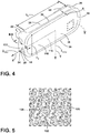
FIG. 4 is a rear top perspective view of a monitoring system with a coupling layer disposed on a rear attachment surface of a resilient housing of the present disclosure; -
FIG. 5 is an expanded view of the coupling layer ofFIG. 4 taken at area V with nano-cavities defined thereon; -
FIG. 6 is a top perspective view of a resilient housing of the present disclosure; -
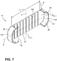
FIG. 7 is a top perspective view of a resilient housing of the present disclosure; -
FIG. 8 is a top elevational view of a resilient housing of the present disclosure; and -
FIG. 9 is an enlarged cross-sectional view of the resilient housing ofFIG. 8 taken at line IX-IX. - The components in the figures are not necessarily to scale, emphasis instead being placed upon illustrating the principles described herein.
- The present illustrated embodiments reside primarily in combinations of apparatus components related to a resilient housing for a camera. Accordingly, the apparatus components have been represented, where appropriate, by conventional symbols in the drawings, showing only those specific details that are pertinent to understanding the embodiments of the present disclosure so as not to obscure the disclosure with details that will be readily apparent to those of ordinary skill in the art having the benefit of the description herein. Further, like numerals in the description and drawings represent like elements.
- For purposes of description herein, the terms "upper," "lower," "right," "left," "rear," "front," "vertical," "horizontal," and derivatives thereof shall relate to the disclosure as oriented in
FIG. 1 . Unless stated otherwise, the term "front" shall refer to the surface of the element closer to an intended viewer, and the term "rear" shall refer to the surface of the element further from the intended viewer. However, it is to be understood that the disclosure may assume various alternative orientations, except where expressly specified to the contrary. It is also to be understood that the specific devices and processes illustrated in the attached drawings, and described in the following specification are simply exemplary embodiments of the inventive concepts defined in the appended claims. Hence, specific dimensions and other physical characteristics relating to the embodiments disclosed herein are not to be considered as limiting, unless the claims expressly state otherwise. - The terms "including," "comprises," "comprising," or any other variation thereof, are intended to cover a non-exclusive inclusion, such that a process, method, article, or apparatus that comprises a list of elements does not include only those elements but may include other elements not expressly listed or inherent to such process, method, article, or apparatus. An element proceeded by "comprises a ... " does not, without more constraints, preclude the existence of additional identical elements in the process, method, article, or apparatus that comprises the element.
- Referring to
FIGS. 1-9 ,reference numeral 10 generally designates a monitoring system for anappliance 12 that includes aresilient housing 14 having afirst end 16 and asecond end 18. Theresilient housing 14 includes retention features 20 and abody 22 that has arear attachment surface 24 and asupport surface 26. Thebody 22 also includes first and secondelongated walls second end walls support surface 26. Acoupling layer 36 is disposed on therear attachment surface 24 of thebody 22, and adata collection device 38 is disposed on thesupport surface 26 of thebody 22. Thedata collection device 38 is operably coupled to theresilient housing 14 via the retention features 20. - Referring to
FIGS. 1-3 , theresilient housing 14 is illustrated within theappliance 12. Theappliance 12 is illustrated as a French-door style refrigerator with a bottom-mounteddrawer 44 and first andsecond doors resilient housing 14 may be used in other appliances, as well as other cabinetry, pantries, and similar storage compartments.Storage bins 56,drawers 60, andshelves 64 may be coupled to aninterior surface 68 of theappliance 12, and each is configured to support and store consumer items typically stored in theappliance 12. - In a conventional refrigerator, a user may repeatedly open and close the
doors - It is advantageous to have a
monitoring system 10 coupled to theinterior surface 68 of theappliance 12 to internally monitor the contents within theappliance 12. Theresilient housing 14 provides flexible removal of themonitoring system 10 from theappliance 12. Themonitoring system 10 may also be referred to as a monitoring assembly. As illustrated inFIGS. 1 and2 , themonitoring system 10 is positioned on arear wall 74 of theappliance 12. It is also contemplated that themonitoring system 10 can be positioned in any location within theappliance 12 to maximize the images and views within theappliance 12. Additionally or alternatively, a plurality ofmonitoring systems 10 may be coupled within theappliance 12 and communicatively coupled, such that a variety of images are communicated between themonitoring system 10 and, ultimately, to the user. - With further reference to
FIGS. 1-3 , themonitoring system 10 is communicatively coupled to acontroller 76 that receives the images from thedata collection device 38. Thedata collection device 38 may include a variety of devices, such as data sensors, configured to collect various data within theappliance 12. By way of example, not limitation, thedata collection device 38 described herein is an imager. Theimager 38 is retained within theresilient housing 14, and theresilient housing 14 is operably coupled to theinterior surface 68 of theappliance 12. It is generally contemplated that theimager 38 may be a camera or other vision-based device configured to capture image data of aninterior 84 of theappliance 12. - Referring to
FIGS. 2-5 , theimager 38 includes alens 90 and acurved surface 94 disposed around thelens 90 in which asensor 96 can be disposed to sense the amount of light present within theappliance 12. Thelens 90, thecurved surface 94, and thesensor 96 are generally disposed within anangular casing 98, described below. In one instance, it is contemplated that theimager 38 may collect data when the light present in theappliance 12 reaches a particular visible or non-visible illumination level. Alternatively, theimager 38 may be triggered by a motion sensor that detects movement of the door, or a proximity sensor that detects movement within a close range of the proximity sensor. By way of example, not limitation, the consumer typically opens thedoors imager 38. Theimager 38 can utilize the light generated by theappliance 12 in addition to the natural light that may enter theappliance 12 with thedoors sensor 96 detects the light, movement of thecontroller 76 activates theimager 38 to capture an image. Theangular casing 98, mentioned above, is movable about an axis to capture a multitude of images of the interior 84 of theappliance 12. It is also contemplated that theangular casing 98 may be fixed in a position, such that theimager 38 is focused on a single section of theappliance 12. - Conventional systems may utilize a rigid structure that adheres to a side of a conventional appliance. As a result of the rigidity of the conventional structure, the conventional systems may be difficult to remove from the conventional appliance. Accordingly, the residue of the adhesives used to bond the conventional system to the side of the conventional appliance may remain on the conventional appliance after attempted removal.
- With further reference to
FIGS. 2-5 , the retention features 20 operably couple theimager 38 within theresilient housing 14. As illustrated, the retention features 20 may be referred to as a plurality of retention features 20 and each have a semi-circular construction to generally cradle theimager 38 within theresilient housing 14 against thesupport surface 26. The retention features 20 as illustrated inFIGS. 3 and4 include aretention feature 20 at each corner of theresilient housing 14. Stated differently, thefirst end 16 and thesecond end 18 of theresilient housing 14 each include afirst retention feature 110 and asecond retention feature 112. The first and second retention features 110, 112 cooperate to retain theimager 38 within theresilient housing 14 and are described in more detail below. - The
support surface 26 of thebody 22 abuts arear surface 114 of theimager 38 to further support theimager 38 within theresilient housing 14. Additionally or alternatively, thesupport surface 26 of theresilient housing 14 may provide a structural backing to theimager 38, such that therear surface 114 of theimager 38 may be integral with thesupport surface 26. It is generally contemplated that to remove theresilient housing 14 from theinterior surface 68 of theappliance 12, theimager 38 is first removed from theresilient housing 14 as theimager 38 is typically a rigid body. The rigidity of a body, such as theimager 38, can make removal of themonitoring system 10 more difficult. Theresilient housing 14 is formed from a generally pliable material and is contemplated to be generally flexible about a y-axis Y and generally rigid about an x-axis X, described in more detail below. - The
resilient housing 14 is selectively coupled to theinterior surface 68 of theappliance 12. Thecoupling layer 36 that is disposed on therear attachment surface 24 of theresilient housing 14 can be securely, but removably, coupled to theinterior surface 68 of theappliance 12. It is generally contemplated that thecoupling layer 36 includes first andsecond surfaces first surface 116 is coupled to therear attachment surface 24 of thebody 22. Typically, thefirst surface 116 is a standard adhesive material that securely adheres thecoupling layer 36 to therear attachment surface 24, while thesecond surface 118 can be a micro-suction adhesive configured to be removable from a mounting surface to which thesecond surface 118 is coupled. Thesecond surface 118, formed from the micro-suction adhesive, has a plurality of nano-cavities 120 disposed along thesecond surface 118. Each of the nano-cavities 120 contains air, which is removed from the nano-cavities 120 upon compression of thesecond surface 118. - With further reference to
FIGS. 2-5 , the compression of the nano-cavities 120 activates the micro-suction adhesive to seal against, for example, theinterior surface 68 of theappliance 12. This adherence defines a partial vacuum between theinterior surface 68 and thecoupling layer 36 and, as a result, theresilient housing 14. As the air is compressed from each nano-cavity 120, the compressed portions of thesecond surface 118 of thecoupling layer 36 are suctioned to theinterior surface 68 of theappliance 12. It is generally contemplated that thiscoupling layer 36 may be used on aresilient housing 14 of various sizes, such that the level of force applied to evacuate the nano-cavities 120 proportionally increases with the size of theresilient housing 14. Additionally, the amount of pressure exerted against thecoupling layer 36 to evacuate the nano-cavities 120 may inform the degree of attachment of theresilient housing 14 to theinterior surface 68 of theappliance 12. By way of example, not limitation, the more pressure that is applied to theresilient housing 14, upon coupling theresilient housing 14 to theappliance 12, the stronger the bond between thecoupling layer 36 and theappliance 12. - It is also contemplated that the
second surface 118 of thecoupling layer 36 may include a traditional adhesive generally known in the art. The traditional adhesive may be similar to the standard adhesive material used on thefirst surface 116 or may be a different traditional adhesive known in the art. The traditional adhesive may fix theresilient housing 14 to theinterior surface 68 of theappliance 12. Additionally or alternatively, the traditional adhesive may allow theresilient housing 14 to be selectively removed from and readjusted relative to theinterior surface 68. Thecoupling layer 36 primarily discussed in the present disclosure is one that allows the selective removal of theresilient housing 14 from theinterior surface 68 whether using the micro-suction adhesive or the traditional adhesive. - Referring now to
FIGS. 3-7 , theimager 38 is removably coupled to thesupport surface 26 via the retention features 20 to aid the removal and/or adjustment of theresilient housing 14. It is generally contemplated that the first and secondelongated walls second end walls body 22, in addition to the retention features 20, are configured to support theimager 38 within theresilient housing 14. The first and secondelongated walls resilient housing 14. The first andsecond end walls first end wall 32 is defined on thefirst end 16 of theresilient housing 14, and thesecond end wall 34 is defined on thesecond end 18 of theresilient housing 14. - Additionally or alternatively, the
first retention feature 110 and thesecond retention feature 112 illustrated inFIG. 7 are disposed on thefirst end 16 and thesecond end 18, respectively. It is further contemplated that the retention features 20 may be configured to be inserted into theimager 38. By way of example, not limitation, the retention features 20 may be posts that extend through theimager 38 so theresilient housing 14 defines a backing of theimager 38. In any one of the above constructions, theimager 38 is removably coupled to theresilient housing 14 via the retention features 20. - It is generally contemplated that the
elongated walls end walls FIG. 3 , the thickness T2 of theend walls elongated walls end walls body 22 with additional structural support to retain theimager 38 on thesupport surface 26. The lesser thickness T1 of theelongated walls end walls resilient housing 14. The thickness T2 can help minimize rotation of theresilient housing 14 about the x-axis X, while the thickness T1 of theelongated walls resilient housing 14 about the y-axis Y. - With further reference to
FIGS. 3-7 , the assembledmonitoring system 10 may have an increased weight as compared to theresilient housing 14 alone due to the weight of theimager 38, which increases the load L1 placed upon thecoupling layer 36. Specifically, gravitational force G will result in a peel-force Px acting upon theresilient housing 14, which will affect the adherence of themonitoring system 10 to theinterior surface 68 of theappliance 12. To combat the gravitational force G, theresilient housing 14 is highly resistant to the peel-force Px about the x-axis X, which minimizes the potential of peeling from the interior surface 68 (FIG. 2 ) under gravitational force G. To further minimize the effects of the gravitational force G about the x-axis X of theresilient housing 14, thebody 22 of theresilient housing 14 may be additionally braced withreinforcement ribs 130 disposed along a length L2 of thebody 22. In addition to the first andsecond end walls reinforcement ribs 130 increase the general rigidity of thebody 22 of theresilient housing 14. Thebody 22 is less likely to bend about the x-axis X as a result of the increased rigidity with thereinforcement ribs 130. Thereinforcement ribs 130 extend perpendicular to the x-axis X of thebody 22 to resist peeling about the x-axis X. In general, the x-axis X may be defined as extending between acentral location 132 of the first andsecond end walls resilient housing 14. - As the
reinforcement ribs 130 are perpendicular to the x-axis X, thereinforcement ribs 130 are accordingly parallel along the y-axis Y to allow bending and flexing of theresilient housing 14 relative to the y-axis Y. The y-axis Y is defined parallel to the first andsecond end walls body 22 and thereinforcement ribs 130. When bending theresilient housing 14 about the y-axis Y, theimager 38 is first removed from theresilient housing 14. Although theresilient housing 14 has a greater ability to bend, flex, and be removed along the y-axis Y, the insertion of theimager 38 within the retention features 20 of theresilient housing 14 minimizes the potential of bending and removal of themonitoring system 10 from theinterior surface 68 of theappliance 12. - Referring now to
FIG. 7 , an additional aspect of theresilient housing 14 is illustrated as having thefirst retention feature 110 on thefirst end 16 of theresilient housing 14, and thesecond retention feature 112 on thesecond end 18. In the depicted aspect, the first and second retention features 110, 112 have a generally semi-circular cross-section configured to cradle theimager 38. Thebody 22 of theresilient housing 14 is free from both theelongated walls end walls resilient housing 14 about the x-axis X. Stated differently, it is generally contemplated that the first and second retention features 110, 112 can generally replace the first andsecond end walls FIG. 6 . It is generally contemplated that the first and second retention features 110, 112, as illustrated inFIG. 7 , may increase the rigidity of theresilient housing 14 to the extent that thebody 22 of theresilient housing 14 can be free from the first and secondelongated walls FIG. 7 extend along a greater portion of thebody 22 as compared to the retention features 20 inFIG. 6 . For purposes of this disclosure, the aspect illustrated inFIG. 6 is described herein. However, it is also contemplated that the description described below also applies to the aspect as described with relation toFIG. 7 . - Referring now to
FIGS. 2 and6-9 , the peel-force Py about the y-axis Y is typically much lower than the peel-force Px about the x-axis X as a result of the overall height HR and thickness TR of theresilient housing 14. As described in further detail below, theresilient housing 14 has a small cross-sectional area moment of inertia IA-A,y relative to the y-axis Y, such that the resistance to peeling about the y-axis Y is less than the resistance to peeling about the x-axis X. In addition to the moment of inertia IA-A,y relative to the y-axis Y, theresilient housing 14 also has a cross-sectional area moment of inertia IB-B,x relative to the x-axis X, which for purposes of this disclosure is greater than the moment of inertia IA-A,y about the y-axis Y. - The moments of inertia IA-A,y, IB-B,x are generally defined as a measure of the resilient housing's 14 resistance to rotation, such as peeling or bending, about the y-axis Y and the x-axis X, respectively. As a result of the smaller moment of inertia IA-A,y relative to the y-axis Y, the user can easily peel and remove the
resilient housing 14 from theinterior surface 68 of theappliance 12 about the y-axis Y. Due to the relatively low resistance to peeling about the y-axis Y, thesecond surface 118 of thecoupling layer 36 easily releases from theinterior surface 68 of theappliance 12, and theinterior surface 68 is free from the residue after the removal of theresilient housing 14. As mentioned above, the bending of theresilient housing 14 about the y-axis Y is defined by the cross-sectional moment of inertia IA-A,y taken at point A-A. The cross-sectional moment of inertia IA-A,y relative to the y-axis Y of theresilient housing 14 is calculated as IA-A,y=∫z2dA. Similarly, the cross-sectional moment of inertia IB-B,x relative to the x-axis X of theresilient housing 14 is calculated as IB-B,x=∫z2dA, discussed in further detail below. The moments of inertia IA-A,y, IB-B,x are based upon the integral of a distance z squared from the y-axis Y or the x-axis X, respectively, and multiplied by the differential area dA. - With further reference to
FIGS. 2 and6-9 , the moment of inertia IA-A,y relative to the y-axis Y is proportional to the height HR of theresilient housing 14 and is also proportional to the thickness TR of theresilient housing 14 cubed. In order to determine the specific moment of inertia IA-A,y relative the y-axis Y, the equation IA-A,y=∫z2dA is localized to the cross-sectional point A-A taken about the y-axis Y. In addition, the height HR of theresilient housing 14 is determined to maximize the amount of thecoupling layer 36 that will securely, but removably, couple themonitoring system 10 to theinterior surface 68 of theappliance 12. In addition, the thickness TR of thebody 22 is determined relative to the height HR of theresilient housing 14 to maintain the flexibility of theresilient housing 14 so thecoupling layer 36 can be easily removed from theinterior surface 68 of theappliance 12. - In general, the smaller the thickness TR of the
body 22, the lower the moment of inertia IA-A,y, which leads to a more flexibleresilient housing 14 about the y-axis Y to enable easier peeling of thecoupling layer 36 from the mounting surface, such as theinterior surface 68. Accordingly, the greater the thickness TR the more difficult and the more rigid theresilient housing 14. Thus, although theresilient housing 14 may take various shapes and constructions, it is generally desirable that the thickness TR of theresilient housing 14 is minimal relative to the height HR of theresilient housing 14 to maintain the flexibility of theresilient housing 14 about the y-axis Y. For example, the first and secondelongated walls second end walls resilient housing 14. The moment of inertia IA-A,y about the y-axis Y is typically a measure of the efficiency of the cross-sectional shape of theresilient housing 14 to resist bending. As theresilient housing 14 is configured to bend and flex about the y-axis Y, the moment of inertia IA-A,y is relatively small. Thus, the thickness TR of theresilient housing 14 is proportionally small, such that the thinner theresilient housing 14 the smaller the moment of inertia IA-A,y. - Comparatively, the moment of inertia IB-B,x of a cross-sectional point B-B of the
resilient housing 14 relative to the x-axis X is affected by, but not necessarily proportional to, the length L2 of theresilient housing 14, the thickness TR of theresilient housing 14 cubed, and the thickness T2 of the first andsecond end walls resilient housing 14. In general, it is desirable to have the largest possible moment of inertia IB-B,x relative the x-axis X to resist bending and flexion. The length L2 of theresilient housing 14 is generally determined to maximize the amount of thecoupling layer 36 attached to therear attachment surface 24 of theresilient housing 14 while maintaining a large moment of inertia IB-B,x about the x-axis X. In addition, the thickness TR of theresilient housing 14 is determined to maximize the bending about the y-axis Y of theresilient housing 14 and minimize bending about the x-axis X for purposes of selectively coupling theresilient housing 14 to theappliance 12. - Referring still to
FIGS. 2 and6-9 , in order to maximize the moment of inertia IB-B,x about the x-axis X, the dimensions of the first andsecond end walls resilient housing 14 may resist bending about the x-axis X that may otherwise occur as a result of the gravitational force G acting upon themonitoring system 10. In general, increasing a height of the retention features 20 and the first andsecond end walls resilient housing 14 may resist bending about the x-axis X to a greater degree when the retention features 20 have a larger height. Thereinforcement ribs 130 may be added to further increase the moment of inertia IB-B,x, and consequently decrease bending about the x-axis X. As mentioned above, thereinforcement ribs 130 are disposed about the y-axis Y and, accordingly, provide further resistance to bending relative the x-axis X for theresilient housing 14 while flexion of theresilient housing 14 relative the y-axis Y is generally uninhibited. - Referring again to
FIGS. 1-9 and as generally discussed above, users typically repeatedly open and close thedoors appliance 12 to determine what items may need to be replenished. In an effort to improve user experience and efficiency of replenishing items, themonitoring system 10 may communicate with the user's portable computing device and/or other programmable software devices that may communicate with themonitoring system 10. Based on the shared information, themonitoring system 10 may update the user on the current status of items within theappliance 12. Accordingly, the user may receive current information on the items within theappliance 12 to inform the user during a process, such as shopping or ordering of items. In addition, themonitoring system 10 may communicate with the controller and the user's portable computing device to deliver recipe options based on the data collected by themonitoring system 10. To execute such functions, it is generally contemplated that themonitoring system 10 may be communicatively coupled to the controller that is connected to a network to send the information to the user's portable computing device or other software device. - In addition to such informative advantages, the relatively small moment of inertia relative the y-axis Y provides that the
coupling layer 36 may be easily removed from theinterior surface 68 of theappliance 12 while theinterior surface 68 is free from residue after the removal of theresilient housing 14 from theappliance 12. Thus, the user may remove and replace themonitoring system 10 in various locations within theappliance 12 without excessive cleaning or abrasive measures to remove residue of thecoupling layer 36 that may otherwise be on theinterior surface 68 of theappliance 12 after the removal of theresilient housing 14. This decrease in residue is a result of the small moment of inertia IA-A,y about the y-axis Y of theresilient housing 14 as compared to the greater moment of inertia IB-B,x about the x-axis X. - The invention disclosed herein is further summarized in the following paragraphs and is further characterized by combinations of any and all of the various aspects described therein.
- According to one aspect of the present disclosure, a monitoring system for an appliance includes a resilient housing that has a first end and a second end. The resilient housing includes retention features, and a body that has a rear attachment surface and a support surface. The body also includes first and second elongated walls and first and second end walls that cooperate to define the support surface. The resilient housing further includes a coupling layer that is disposed on the rear attachment surface of the body, and a data collection device that is disposed on the support surface of the body and is operably coupled to the resilient housing via the retention features.
- According to another aspect, a data collection device is an imager that is configured to collect image data of an interior of said appliance.
- According to another aspect, a resilient housing further includes a plurality of reinforcement ribs that are disposed along a support surface of a body.
- According to another aspect, retention features include a first retention feature and a second retention feature.
- According to another aspect, first and second retention features are disposed on both a first end and a second end of a resilient housing.
- According to another aspect, a first retention feature is disposed on a first end of a resilient housing, and a second retention feature is disposed on a second end of the resilient housing.
- According to another aspect, a body is configured to bend about a y-axis that is defined parallel to first and second retention features.
- According to another aspect, a resilient housing has a y-axis cross-sectional moment of inertia that is defined as IA-A,y=∫z2dA and an x-axis cross-sectional moment of inertia that is defined as IB-B,x=∫z2dA.
- According to another aspect of the present disclosure, a monitoring assembly for an appliance includes a resilient housing including a plurality of retention features and a body that extend between the plurality of retention features. The body has a rear attachment surface and a support surface that is defined between the plurality of retention features. A data collection device is disposed on the support surface of the body and is operably coupled to the body of the resilient housing via the plurality of retention features. A coupling layer is disposed on the rear attachment surface of the body.
- According to another aspect, a resilient housing includes a first end and a second end. A plurality of retention features are disposed on the first and second ends of the resilient housing.
- According to another aspect, a body of a resilient housing includes a first end wall and a second end wall. The first end wall is disposed on a first end of the resilient housing between a first retention feature and a second retention feature.
- According to another a plurality of retention features includes a first retention feature and a second retention feature. The first retention feature is disposed on a first end of a resilient housing and the second retention feature is disposed on a second end of the resilient housing.
- According to another aspect, a body includes a first elongated wall and a second elongated wall.
- According to another aspect, a resilient housing has a y-axis cross-sectional moment of inertia that is defined as IA-A,y=∫z2dA and an x-axis cross-sectional moment of inertia that is defined as IB-B,x=∫z2dA.
- According to yet another aspect of the present disclosure, a resilient housing for a monitoring system includes a plurality of retention features, and a body that has a first end and a second end and extends between the plurality of retention features. The body includes a support surface that is defined between the plurality of retention features by elongated walls and end walls and a rear attachment surface. A resilient housing for a monitoring system further includes a coupling layer that is disposed on the rear attachment surface of the body.
- According to another aspect, a coupling layer includes a micro-suction adhesive that has a plurality of nano-cavities.
- According to another aspect, a plurality of retention features and end walls of a body are configured to resist bending of the body about an x-axis that is defined perpendicular to the end walls.
- According to another aspect, a body is configured to bend about a y-axis that is defined parallel to end walls of the body.
- According to another aspect, end walls of a body have a thickness that is greater than a thickness of elongated walls of the body.
Claims (13)
- A resilient housing (14) for a monitoring system (10), comprising:a plurality of retention features (20);a body (22) extending between the plurality of retention features (20) and having a first end (16) and a second end (18), the body (22) including:a support surface (26) defined between the plurality of retention features (20) by elongated walls (28, 30) and end walls (32, 34); anda rear attachment surface (24); anda coupling layer (36) disposed on the rear attachment surface (24) of the body (22), wherein said coupling layer (36) includes a micro-suction adhesive having a plurality of nano-cavities (120) and wherein the end walls (32, 34) of the body (22) have a thickness that is greater than a thickness of the elongated walls (28, 30) of the body (22).
- The resilient housing (14) of claim 1, further comprising:
a plurality of reinforcement ribs (130) disposed along a length of the support surface (26). - The resilient housing (14) of claim 1 or 2, wherein the plurality of retention features (20) and the end walls (32, 34) of the body (22) are configured to resist bending of the body (22) about an x-axis that is defined perpendicular to the end walls (32, 34).
- The resilient housing (14) of any one of claims 1-3, wherein the body (22) is configured to bend about a y-axis defined parallel to the end walls (32, 34) of the body (22).
- The resilient housing (14) of any one of claims 1-4, wherein the body (22) has a y-axis cross-sectional moment of inertia defined as IA-A,y=∫z2dA and an x-axis cross-sectional moment of inertia defined as IB-B,x=∫z2dA.
- The resilient housing (14) of any one of claims 1-5, wherein the plurality of retention features (20) include a first retention feature (110) and a second retention feature (112).
- The resilient housing (14) of claim 6, wherein the first and second retention features (110, 112) are disposed on both the first end (16) and the second end (18) of the body (22).
- The resilient housing (14) of claim 6, wherein the first retention feature (110) is disposed on the first end (16) of the body (22) and the second retention feature (112) is disposed on the second end (18) of the body (22).
- The resilient housing (14) of any one of claims 1-8, wherein the plurality of retention features (20) are disposed on the first and second ends (16, 18) of the body (22).
- The resilient housing (14) of any one of claims 1-9, wherein the end walls (32, 34) of the body (22) include a first end wall (32) and a second end wall (34).
- The resilient housing (14) of claim 10, wherein the first end wall (32) is disposed on the first end (16) of the body (22) between a first retention feature (110) and a second retention feature (112).
- A monitoring system (10) including the resilient housing (14) of any one of claims 1-11.
- The monitoring system (10) of claim 12, wherein a data collection device (38) is disposed on the support surface (26) of the body (22) and operably coupled to the resilient housing (14) via the plurality of retention features (20).
Applications Claiming Priority (2)
| Application Number | Priority Date | Filing Date | Title |
|---|---|---|---|
| US201962954849P | 2019-12-30 | 2019-12-30 | |
| US17/120,650 US11656025B2 (en) | 2019-12-30 | 2020-12-14 | Resilient housing |
Publications (1)
| Publication Number | Publication Date |
|---|---|
| EP3846436A1 true EP3846436A1 (en) | 2021-07-07 |
Family
ID=73855201
Family Applications (1)
| Application Number | Title | Priority Date | Filing Date |
|---|---|---|---|
| EP20214782.3A Withdrawn EP3846436A1 (en) | 2019-12-30 | 2020-12-16 | Resilient housing |
Country Status (2)
| Country | Link |
|---|---|
| US (1) | US11656025B2 (en) |
| EP (1) | EP3846436A1 (en) |
Families Citing this family (3)
| Publication number | Priority date | Publication date | Assignee | Title |
|---|---|---|---|---|
| DE102021200495A1 (en) * | 2021-01-20 | 2022-07-21 | BSH Hausgeräte GmbH | Household appliance with a camera and a module fixed in position in a housing shaft of the camera, and method |
| DE102021128847A1 (en) | 2021-07-30 | 2023-02-02 | Liebherr-Hausgeräte Ochsenhausen GmbH | refrigerator and/or freezer |
| WO2025009210A1 (en) * | 2023-07-04 | 2025-01-09 | パナソニックIpマネジメント株式会社 | Camera unit |
Citations (4)
| Publication number | Priority date | Publication date | Assignee | Title |
|---|---|---|---|---|
| CN203911533U (en) * | 2014-05-28 | 2014-10-29 | 黄河科技学院 | Mountain-bike-mounted cell phone power-supplying device |
| US20150070575A1 (en) * | 2013-09-11 | 2015-03-12 | Podo Labs, Inc. | Digital camera utilizing surface for temporary mounting |
| CN206894737U (en) * | 2017-06-30 | 2018-01-16 | 深圳市凌捷信科技有限公司 | Containment vessel |
| US9969450B1 (en) * | 2014-03-14 | 2018-05-15 | Mace Group, Inc. | Bicycle cellular phone holder structure |
Family Cites Families (22)
| Publication number | Priority date | Publication date | Assignee | Title |
|---|---|---|---|---|
| JP2003207258A (en) | 2002-01-16 | 2003-07-25 | Toshiba Corp | refrigerator |
| US20060096303A1 (en) * | 2004-11-10 | 2006-05-11 | Kavounas Gregory T | Home refrigerator systems imaging their interior and methods |
| US8755852B2 (en) * | 2009-02-06 | 2014-06-17 | Speculative Product Design, Llc | One piece co-formed exterior hard shell case with an elastomeric liner for mobile electronic devices |
| WO2011053740A1 (en) * | 2009-10-28 | 2011-05-05 | Belkin International, Inc. | Portable multi-media communication device protective carrier and method of manufacture therefor |
| MX345636B (en) * | 2011-12-22 | 2017-02-08 | Treefrog Dev Inc | ACCESSORIES FOR USE WITH ACCOMMODATION FOR AN ELECTRONIC DEVICE. |
| US20140035511A1 (en) * | 2012-08-06 | 2014-02-06 | Fka Distributing Co., Llc | Battery Case for a Mobile Device |
| JP6121802B2 (en) * | 2012-10-12 | 2017-04-26 | 東芝ライフスタイル株式会社 | refrigerator |
| MX342133B (en) * | 2013-02-01 | 2016-09-14 | Treefrog Dev Inc | Encasements for an electronic device having a biometric scanner. |
| JP6498866B2 (en) * | 2013-03-12 | 2019-04-10 | 東芝ライフスタイル株式会社 | Refrigerator, camera device |
| JP6391943B2 (en) | 2013-03-12 | 2018-09-19 | 東芝ライフスタイル株式会社 | Refrigerator, camera device, internal image display program |
| US9644783B2 (en) * | 2013-03-16 | 2017-05-09 | James A Rinner | Phone camera tablet bipod support system |
| US9124350B2 (en) * | 2013-06-21 | 2015-09-01 | Francesco BIANCAMANO | Case for mobile device |
| US9247795B2 (en) * | 2013-06-28 | 2016-02-02 | Spigen Korea Co., Ltd. | Case having a shock absorbing structure for electronic devices |
| DE102013216759A1 (en) | 2013-08-23 | 2015-02-26 | BSH Bosch und Siemens Hausgeräte GmbH | Refrigeration unit with a camera module |
| CN110995983A (en) | 2013-08-28 | 2020-04-10 | 东芝生活电器株式会社 | Camera device for storage box |
| USD798285S1 (en) * | 2015-02-16 | 2017-09-26 | Samsung Electronics Co., Ltd. | Cover for electronic communications device |
| USD791757S1 (en) * | 2015-02-16 | 2017-07-11 | Samsung Electronics Co., Ltd. | Cover for electronic communications device |
| US10237384B2 (en) * | 2016-03-09 | 2019-03-19 | Josh Holder | Hands-free mount for mobile devices |
| US10030806B2 (en) * | 2016-08-30 | 2018-07-24 | Htc Corporation | Fixing support and fixing module |
| US10863013B2 (en) * | 2016-10-06 | 2020-12-08 | Vibes Audio Llc | Portable device case for removably attaching accessories |
| US9843657B1 (en) * | 2016-10-27 | 2017-12-12 | W. Jason Guzek | Mobile computing/communicating attachment device |
| US11272144B2 (en) * | 2020-01-15 | 2022-03-08 | George Gorgees | Large vehicle backup camera apparatus |
-
2020
- 2020-12-14 US US17/120,650 patent/US11656025B2/en active Active
- 2020-12-16 EP EP20214782.3A patent/EP3846436A1/en not_active Withdrawn
Patent Citations (4)
| Publication number | Priority date | Publication date | Assignee | Title |
|---|---|---|---|---|
| US20150070575A1 (en) * | 2013-09-11 | 2015-03-12 | Podo Labs, Inc. | Digital camera utilizing surface for temporary mounting |
| US9969450B1 (en) * | 2014-03-14 | 2018-05-15 | Mace Group, Inc. | Bicycle cellular phone holder structure |
| CN203911533U (en) * | 2014-05-28 | 2014-10-29 | 黄河科技学院 | Mountain-bike-mounted cell phone power-supplying device |
| CN206894737U (en) * | 2017-06-30 | 2018-01-16 | 深圳市凌捷信科技有限公司 | Containment vessel |
Also Published As
| Publication number | Publication date |
|---|---|
| US20210199375A1 (en) | 2021-07-01 |
| US11656025B2 (en) | 2023-05-23 |
Similar Documents
| Publication | Publication Date | Title |
|---|---|---|
| US11656025B2 (en) | Resilient housing | |
| US11503926B2 (en) | Shopping shelf | |
| USD494050S1 (en) | Hanger bracket for cabinet door storage rack | |
| USD483250S1 (en) | Hanger bracket for cabinet door storage rack | |
| US8016135B2 (en) | Product display support systems and methods | |
| US20050279648A1 (en) | Hanger for case holding nonprescription reading glasses | |
| USD463697S1 (en) | Hanging storage unit having multiple baskets | |
| US7523909B1 (en) | Display hanger for non-prescription reading glasses and case | |
| US5743605A (en) | Information display and article storage and dispensing apparatus | |
| USD462254S1 (en) | Wall mountable hose hanger | |
| EP2273444A3 (en) | Media enabled advertising shopping cart system | |
| USD479423S1 (en) | Athletic equipment hanger | |
| USD475879S1 (en) | Display rack for sportsballs | |
| US7308770B2 (en) | Electronic shelf label holder for scanner plate and wire supports | |
| US7445127B2 (en) | Universal shoe rack | |
| USD485708S1 (en) | Easel | |
| JP2003227681A (en) | Storage element for refrigerator | |
| USD541996S1 (en) | Liquid-dispensing attachment for vacuum cleaners | |
| JPH08303914A (en) | Freezer refrigerator | |
| JP2005204824A (en) | Card holder and its fitting structure | |
| US20050092700A1 (en) | Hanging storage unit | |
| CN222335816U (en) | Box shelf assembly and refrigeration equipment | |
| CN222760646U (en) | Bracket | |
| JP3390373B2 (en) | Stand for mobile phone store display | |
| JPH042574Y2 (en) |
Legal Events
| Date | Code | Title | Description |
|---|---|---|---|
| PUAI | Public reference made under article 153(3) epc to a published international application that has entered the european phase |
Free format text: ORIGINAL CODE: 0009012 |
|
| STAA | Information on the status of an ep patent application or granted ep patent |
Free format text: STATUS: THE APPLICATION HAS BEEN PUBLISHED |
|
| AK | Designated contracting states |
Kind code of ref document: A1 Designated state(s): AL AT BE BG CH CY CZ DE DK EE ES FI FR GB GR HR HU IE IS IT LI LT LU LV MC MK MT NL NO PL PT RO RS SE SI SK SM TR |
|
| STAA | Information on the status of an ep patent application or granted ep patent |
Free format text: STATUS: THE APPLICATION IS DEEMED TO BE WITHDRAWN |
|
| 18D | Application deemed to be withdrawn |
Effective date: 20220108 |