EP3846296A1 - Electrical connector having a slot for robotic installation and method of using a robotic installer to install an electrical connector - Google Patents
Electrical connector having a slot for robotic installation and method of using a robotic installer to install an electrical connector Download PDFInfo
- Publication number
- EP3846296A1 EP3846296A1 EP20216775.5A EP20216775A EP3846296A1 EP 3846296 A1 EP3846296 A1 EP 3846296A1 EP 20216775 A EP20216775 A EP 20216775A EP 3846296 A1 EP3846296 A1 EP 3846296A1
- Authority
- EP
- European Patent Office
- Prior art keywords
- electrical connector
- robotic
- slot
- members
- installer
- Prior art date
- Legal status (The legal status is an assumption and is not a legal conclusion. Google has not performed a legal analysis and makes no representation as to the accuracy of the status listed.)
- Pending
Links
Images



Classifications
-
- H—ELECTRICITY
- H01—ELECTRIC ELEMENTS
- H01R—ELECTRICALLY-CONDUCTIVE CONNECTIONS; STRUCTURAL ASSOCIATIONS OF A PLURALITY OF MUTUALLY-INSULATED ELECTRICAL CONNECTING ELEMENTS; COUPLING DEVICES; CURRENT COLLECTORS
- H01R43/00—Apparatus or processes specially adapted for manufacturing, assembling, maintaining, or repairing of line connectors or current collectors or for joining electric conductors
- H01R43/26—Apparatus or processes specially adapted for manufacturing, assembling, maintaining, or repairing of line connectors or current collectors or for joining electric conductors for engaging or disengaging the two parts of a coupling device
-
- H—ELECTRICITY
- H01—ELECTRIC ELEMENTS
- H01R—ELECTRICALLY-CONDUCTIVE CONNECTIONS; STRUCTURAL ASSOCIATIONS OF A PLURALITY OF MUTUALLY-INSULATED ELECTRICAL CONNECTING ELEMENTS; COUPLING DEVICES; CURRENT COLLECTORS
- H01R13/00—Details of coupling devices of the kinds covered by groups H01R12/70 or H01R24/00 - H01R33/00
- H01R13/64—Means for preventing incorrect coupling
-
- H—ELECTRICITY
- H01—ELECTRIC ELEMENTS
- H01R—ELECTRICALLY-CONDUCTIVE CONNECTIONS; STRUCTURAL ASSOCIATIONS OF A PLURALITY OF MUTUALLY-INSULATED ELECTRICAL CONNECTING ELEMENTS; COUPLING DEVICES; CURRENT COLLECTORS
- H01R12/00—Structural associations of a plurality of mutually-insulated electrical connecting elements, specially adapted for printed circuits, e.g. printed circuit boards [PCB], flat or ribbon cables, or like generally planar structures, e.g. terminal strips, terminal blocks; Coupling devices specially adapted for printed circuits, flat or ribbon cables, or like generally planar structures; Terminals specially adapted for contact with, or insertion into, printed circuits, flat or ribbon cables, or like generally planar structures
- H01R12/70—Coupling devices
- H01R12/77—Coupling devices for flexible printed circuits, flat or ribbon cables or like structures
- H01R12/771—Details
- H01R12/774—Retainers
-
- B—PERFORMING OPERATIONS; TRANSPORTING
- B25—HAND TOOLS; PORTABLE POWER-DRIVEN TOOLS; MANIPULATORS
- B25J—MANIPULATORS; CHAMBERS PROVIDED WITH MANIPULATION DEVICES
- B25J11/00—Manipulators not otherwise provided for
-
- B—PERFORMING OPERATIONS; TRANSPORTING
- B25—HAND TOOLS; PORTABLE POWER-DRIVEN TOOLS; MANIPULATORS
- B25J—MANIPULATORS; CHAMBERS PROVIDED WITH MANIPULATION DEVICES
- B25J15/00—Gripping heads and other end effectors
- B25J15/04—Gripping heads and other end effectors with provision for the remote detachment or exchange of the head or parts thereof
-
- B—PERFORMING OPERATIONS; TRANSPORTING
- B25—HAND TOOLS; PORTABLE POWER-DRIVEN TOOLS; MANIPULATORS
- B25J—MANIPULATORS; CHAMBERS PROVIDED WITH MANIPULATION DEVICES
- B25J15/00—Gripping heads and other end effectors
- B25J15/08—Gripping heads and other end effectors having finger members
-
- H—ELECTRICITY
- H01—ELECTRIC ELEMENTS
- H01B—CABLES; CONDUCTORS; INSULATORS; SELECTION OF MATERIALS FOR THEIR CONDUCTIVE, INSULATING OR DIELECTRIC PROPERTIES
- H01B7/00—Insulated conductors or cables characterised by their form
- H01B7/0045—Cable-harnesses
-
- H—ELECTRICITY
- H01—ELECTRIC ELEMENTS
- H01R—ELECTRICALLY-CONDUCTIVE CONNECTIONS; STRUCTURAL ASSOCIATIONS OF A PLURALITY OF MUTUALLY-INSULATED ELECTRICAL CONNECTING ELEMENTS; COUPLING DEVICES; CURRENT COLLECTORS
- H01R12/00—Structural associations of a plurality of mutually-insulated electrical connecting elements, specially adapted for printed circuits, e.g. printed circuit boards [PCB], flat or ribbon cables, or like generally planar structures, e.g. terminal strips, terminal blocks; Coupling devices specially adapted for printed circuits, flat or ribbon cables, or like generally planar structures; Terminals specially adapted for contact with, or insertion into, printed circuits, flat or ribbon cables, or like generally planar structures
- H01R12/70—Coupling devices
- H01R12/77—Coupling devices for flexible printed circuits, flat or ribbon cables or like structures
-
- H—ELECTRICITY
- H01—ELECTRIC ELEMENTS
- H01R—ELECTRICALLY-CONDUCTIVE CONNECTIONS; STRUCTURAL ASSOCIATIONS OF A PLURALITY OF MUTUALLY-INSULATED ELECTRICAL CONNECTING ELEMENTS; COUPLING DEVICES; CURRENT COLLECTORS
- H01R12/00—Structural associations of a plurality of mutually-insulated electrical connecting elements, specially adapted for printed circuits, e.g. printed circuit boards [PCB], flat or ribbon cables, or like generally planar structures, e.g. terminal strips, terminal blocks; Coupling devices specially adapted for printed circuits, flat or ribbon cables, or like generally planar structures; Terminals specially adapted for contact with, or insertion into, printed circuits, flat or ribbon cables, or like generally planar structures
- H01R12/70—Coupling devices
- H01R12/77—Coupling devices for flexible printed circuits, flat or ribbon cables or like structures
- H01R12/771—Details
-
- H—ELECTRICITY
- H01—ELECTRIC ELEMENTS
- H01R—ELECTRICALLY-CONDUCTIVE CONNECTIONS; STRUCTURAL ASSOCIATIONS OF A PLURALITY OF MUTUALLY-INSULATED ELECTRICAL CONNECTING ELEMENTS; COUPLING DEVICES; CURRENT COLLECTORS
- H01R13/00—Details of coupling devices of the kinds covered by groups H01R12/70 or H01R24/00 - H01R33/00
- H01R13/46—Bases; Cases
- H01R13/502—Bases; Cases composed of different pieces
-
- H—ELECTRICITY
- H01—ELECTRIC ELEMENTS
- H01R—ELECTRICALLY-CONDUCTIVE CONNECTIONS; STRUCTURAL ASSOCIATIONS OF A PLURALITY OF MUTUALLY-INSULATED ELECTRICAL CONNECTING ELEMENTS; COUPLING DEVICES; CURRENT COLLECTORS
- H01R13/00—Details of coupling devices of the kinds covered by groups H01R12/70 or H01R24/00 - H01R33/00
- H01R13/46—Bases; Cases
- H01R13/516—Means for holding or embracing insulating body, e.g. casing, hoods
-
- H—ELECTRICITY
- H01—ELECTRIC ELEMENTS
- H01R—ELECTRICALLY-CONDUCTIVE CONNECTIONS; STRUCTURAL ASSOCIATIONS OF A PLURALITY OF MUTUALLY-INSULATED ELECTRICAL CONNECTING ELEMENTS; COUPLING DEVICES; CURRENT COLLECTORS
- H01R13/00—Details of coupling devices of the kinds covered by groups H01R12/70 or H01R24/00 - H01R33/00
- H01R13/58—Means for relieving strain on wire connection, e.g. cord grip, for avoiding loosening of connections between wires and terminals within a coupling device terminating a cable
-
- H—ELECTRICITY
- H01—ELECTRIC ELEMENTS
- H01R—ELECTRICALLY-CONDUCTIVE CONNECTIONS; STRUCTURAL ASSOCIATIONS OF A PLURALITY OF MUTUALLY-INSULATED ELECTRICAL CONNECTING ELEMENTS; COUPLING DEVICES; CURRENT COLLECTORS
- H01R13/00—Details of coupling devices of the kinds covered by groups H01R12/70 or H01R24/00 - H01R33/00
- H01R13/62—Means for facilitating engagement or disengagement of coupling parts or for holding them in engagement
- H01R13/629—Additional means for facilitating engagement or disengagement of coupling parts, e.g. aligning or guiding means, levers, gas pressure electrical locking indicators, manufacturing tolerances
- H01R13/631—Additional means for facilitating engagement or disengagement of coupling parts, e.g. aligning or guiding means, levers, gas pressure electrical locking indicators, manufacturing tolerances for engagement only
- H01R13/6315—Additional means for facilitating engagement or disengagement of coupling parts, e.g. aligning or guiding means, levers, gas pressure electrical locking indicators, manufacturing tolerances for engagement only allowing relative movement between coupling parts, e.g. floating connection
-
- H—ELECTRICITY
- H01—ELECTRIC ELEMENTS
- H01R—ELECTRICALLY-CONDUCTIVE CONNECTIONS; STRUCTURAL ASSOCIATIONS OF A PLURALITY OF MUTUALLY-INSULATED ELECTRICAL CONNECTING ELEMENTS; COUPLING DEVICES; CURRENT COLLECTORS
- H01R2201/00—Connectors or connections adapted for particular applications
- H01R2201/26—Connectors or connections adapted for particular applications for vehicles
Definitions
- the present disclosure generally relates to automotive electrical connectors and, more particularly, to connector features for robotic installation.
- An electrical connector typically comprises a housing having at least a portion of a wire cable disposed therein.
- the electrical connector is electrically connected to another electrical system (e.g., a corresponding electrical connector) and the connection is secured by a connector position assurance (CPA) feature (a clip, a latch, etc.).
- CPA connector position assurance
- Manual installation of electrical connectors by a human installer can be time consuming and costly, particularly for less experienced human installers and for more complex installation projects. Automated installation by a robotic installer may be preferable to manual human installation due to increased speed and decreased costs. The robotic installer, however, must be able to accurately identify the electrical connector and obtain movable control of it in order to complete the robotic installation. Complex visual scanning systems could be utilized by the robotic installer, but this could further increase costs. Accordingly, while conventional electrical connectors and conventional robotic installers work well for their intended purpose, an opportunity exists for improvement in the art of robotic installation of electrical connectors.
- an electrical connector comprises: a housing defining an outer surface, a wire cable at least partially disposed in the housing, and a robotic installation feature at least temporarily attached to or defined in the outer surface of the housing, wherein the robotic installation feature defines a slot that is configured to be interacted with by an end effector of a robotic installer during robotic installation of the electrical connector with a corresponding electrical connector.
- the slot defines an equal armed cross shape.
- the end effector of the robotic installer comprises two members configured to be inserted into the slot and expanded along one of two axes to thereby fix the two members therein and obtain movable control of the electrical connector.
- the two axes are perpendicular to each other to provide for both horizontal and vertical robotic installation of the electrical connector.
- the robotic installation feature defines a predefined hexagonal outer shape such that it is identifiable by the robotic installer.
- the slot defines a hexagonal shape and at least two opposing base slots.
- the end effector comprises at least two members configured to be inserted into the slot and expanded through at least two of the at least two opposing base slots to thereby fix the at least two members therein and obtain movable control of the electrical connector.
- the slot defines four opposing base slots.
- a method of using a robotic installer to install an electrical connector comprises: identifying, by the robotic installer, a robotic installation feature at least temporarily attached to or defined in an outer surface of a housing of the electrical connector, inserting, by the robotic installer, at least two members of an end effector of the robotic installer into a slot defined by the robotic installation feature, expanding, by the robotic installer, the at least two members of the end effector along at least one of two axes to thereby fix the at least two members therein and obtain movable control of the electrical connector, and installing, by the robotic installer, the electrical connector with a corresponding electrical connector.
- installing the electrical connector with another electrical system includes engaging the electrical connector with a connector position assurance (CPA) feature of the corresponding electrical connector.
- the method further comprises upon engaging the electrical connector with the CPA feature of the corresponding electrical connector: retracting, by the robotic installer, the two members of the end effector along the one of the two axes, and removing, by the robotic installer, the two members of the end effector from the slot.
- CPA connector position assurance
- the slot defines an equal armed cross shape the two axes are perpendicular to each other to provide for both horizontal and vertical robotic installation of the electrical connector.
- the robotic installation feature defines a predefined hexagonal outer shape such that it is identifiable by the robotic installer.
- the slot defines a hexagonal shape and at least two opposing base slots.
- the at least two members of the end effector are inserted into the slot and expanded through at least two of the at least two opposing base slots to thereby fix the at least two members therein and obtain movable control of the electrical connector.
- the slot defines four opposing base slots.
- an electrical connector comprises a housing means defining an outer surface, a wire cable means at least partially disposed in the housing means, and a robotic installation feature means at least temporarily attached to or defined in the outer surface of the housing means, wherein the robotic installation feature means defines a slot means for interaction with by an end effector means of a robotic installer means during robotic installation of the electrical connector with a corresponding electrical connector.
- the slot means defines an equal armed cross shape.
- the end effector means of the robotic installer means comprises two member means for insertion into the slot means and expanded along one of two axes to thereby fix the two members therein and obtain movable control of the electrical connector.
- the two axes are perpendicular to each other to provide for both horizontal and vertical robotic installation of the electrical connector.
- the connector 100 comprises a housing 104 defining an outer surface 108.
- the housing 104 has at least a portion of a wire cable 112 disposed therein. While a flat or band-type wire cable is illustrated, it will be appreciated that a single wire or other type of wire cable (e.g., a round wire cable) could be utilized.
- One end of the wire cable 112 is electrically connected to another electrical system or a corresponding electrical connector 116 by connecting one end of the housing 104 to the corresponding electrical connector 116 using connector position assurance (CPA) features 120, 124. As shown, this could include a clip 120 that connects to a complimentary other CPA feature 124.
- CPA connector position assurance
- the connector 100 also comprises a robotic installation feature 128 at least temporarily attached to or defined in its outer surface 108.
- This robotic installation feature 128 could be temporarily and thus removable or detachable after robotic installation.
- the robotic installation feature 128 could be a permanent feature, which could be interacted multiple times (e.g., for robotic installation and subsequent robotic removal and re-installation).
- the robotic installation feature 128 is configured to be interacted with by an end effector 136 of a robotic installer 132.
- the end effector 136 comprises two members 140a, 140b that are configured to be inserted in a slot 144 defined by the robotic installation feature.
- the slot 144 defines an equal armed cross shape (also commonly referred to as a plus sign (+) shape), but it will be appreciated that other slot shaped and end effector configurations could be utilized.
- the robotic installation feature 128 also defines an outer shape 148 that could be predefined and thus easily identifiable by a basic scanning system (not shown) of the robotic installer 132.
- the outer shape 148 is a hexagonal shape, but it will be appreciated that other shapes could be utilized.
- the two members 140a, 140b of the end effector 136 are inserted into the slot 144 and then expanded along one of two axes 152a, 152b to thereby fix the two members 140a, 140b therein and obtain movable control of the electrical connector 100.
- This movable control is obtained by the expansive force maintained by the members 140a, 140b within the slot 144.
- the equal armed cross shape configuration of the slot 144 and the movability of the members 140a, 140b along one of two different axes 152a, 152b allows for both horizontal and vertical robotic installation of the electrical connector 100.
- there are channels extending from the slot 144 under the top surface of the robotic installation feature 128 and the members 140a, 140b each define an L-shape such that their distal ends can engage these channels.
- the electrical connector 200 is configured to electrically connect two wire cables 204a, 204b by compressing or sandwiching them together. While flat or band-type wire cables 204a, 204b are likely used in this configuration of the connector 200, it will be appreciated that single or multiple unshielded round-type wire cables could be utilized.
- a first member 208 interlocks with a second member 212 to thereby secure and electrically connect the wire cables 204a, 204b therein.
- the second member 212 also comprises a robotic installation feature 216, which defines a slot 220 that can be interacted with by an end effector 224 of the robotic installer 132.
- the end effector 224 could also be the same as or similar to the end effector 136 of FIG. 1 .
- the slot 220 defines four opposing base channels or slots 228.
- the robotic installation feature 216 can also define a predefined outer shape (e.g., hexagonal shape 232 as shown) for easy identification by the robotic installer 132.
- the two or more members of the end effector 224 each define an L-shape such that their distal ends can engage the base slots 228.
- the electrical connector 300 comprises many of the same or similar components as illustrated in FIG. 1 and as described in greater detail above.
- This connector 300 comprises a different robotic installation feature 304.
- an end effector 308 of the robotic installer 132 comprises a gripping or grasping member 312 (e.g., a clamp) that is configured to grip or grasp an X-shaped gripping or grasping feature 316 that is attached to the outer surface 108 of the connector 300 via a base member 320 and a shaft 324.
- a gripping or grasping member 312 e.g., a clamp
- X-type shape is shown for the gripping or grasping feature is illustrated, it will be appreciated that other shapes could be utilized (a round bar, a flat bar, a circular disc, an equal armed cross shape, a t-shape, etc.).
- keyhole slots 328 are shown for coupling or attaching the shaft 324 to the base member 320 and to the outer surface 108 of the connector 300, it will be appreciated that other attachment configurations and/or other shaft configurations could be utilized.
- Methods for robotic installation of the connectors 100, 200, 300 illustrated and described herein generally involve the following steps: (1) providing the connector, (2) identifying, by the robotic installer, the robotic installation feature, (3) gaining movable control, by the robotic installer via its end effector, the connector, (4) installing, by the robotic installer, the connector with another electrical system (e.g., another electrical connector) via their respective CPA features, and (5) disengaging, by the robotic installer via its end effector, from the robotic installation feature of the connector to complete the installation process.
- these electrical connectors could be used to connect a central controller or distributed controllers to respective electrical devices or systems (e.g., RADAR, LIDAR, electric traction motors, and the like).
- Example embodiments are provided so that this disclosure will be thorough, and will fully convey the scope to those who are skilled in the art. Numerous specific details are set forth such as examples of specific components, devices, and methods, to provide a thorough understanding of embodiments of the present disclosure. It will be apparent to those skilled in the art that specific details need not be employed, that example embodiments may be embodied in many different forms and that neither should be construed to limit the scope of the disclosure. In some example embodiments, well-known procedures, well-known device structures, and well-known technologies are not described in detail.
- first, second, third, etc. may be used herein to describe various elements, components, regions, layers and/or sections, these elements, components, regions, layers and/or sections should not be limited by these terms. These terms may be only used to distinguish one element, component, region, layer or section from another region, layer or section. Terms such as “first,” “second,” and other numerical terms when used herein do not imply a sequence or order unless clearly indicated by the context. Thus, a first element, component, region, layer or section discussed below could be termed a second element, component, region, layer or section without departing from the teachings of the example embodiments.
- module may refer to, be part of, or include: an Application Specific Integrated Circuit (ASIC); an electronic circuit; a combinational logic circuit; a field programmable gate array (FPGA); a processor or a distributed network of processors (shared, dedicated, or grouped) and storage in networked clusters or datacenters that executes code or a process; other suitable components that provide the described functionality; or a combination of some or all of the above, such as in a system-on-chip.
- the term module may also include memory (shared, dedicated, or grouped) that stores code executed by the one or more processors.
- code may include software, firmware, byte-code and/or microcode, and may refer to programs, routines, functions, classes, and/or objects.
- shared means that some or all code from multiple modules may be executed using a single (shared) processor. In addition, some or all code from multiple modules may be stored by a single (shared) memory.
- group means that some or all code from a single module may be executed using a group of processors. In addition, some or all code from a single module may be stored using a group of memories.
- the techniques described herein may be implemented by one or more computer programs executed by one or more processors.
- the computer programs include processor-executable instructions that are stored on a non-transitory tangible computer readable medium.
- the computer programs may also include stored data.
- Non-limiting examples of the non-transitory tangible computer readable medium are nonvolatile memory, magnetic storage, and optical storage.
- the present disclosure also relates to an apparatus for performing the operations herein.
- This apparatus may be specially constructed for the required purposes, or it may comprise a general-purpose computer selectively activated or reconfigured by a computer program stored on a computer readable medium that can be accessed by the computer.
- a computer program may be stored in a tangible computer readable storage medium, such as, but is not limited to, any type of disk including floppy disks, optical disks, CD-ROMs, magnetic-optical disks, read-only memories (ROMs), random access memories (RAMs), EPROMs, EEPROMs, magnetic or optical cards, application specific integrated circuits (ASICs), or any type of media suitable for storing electronic instructions, and each coupled to a computer system bus.
- the computers referred to in the specification may include a single processor or may be architectures employing multiple processor designs for increased computing capability.
- the present disclosure is well suited to a wide variety of computer network systems over numerous topologies.
- the configuration and management of large networks comprise storage devices and computers that are communicatively coupled to dissimilar computers and storage devices over a network, such as the Internet.
Landscapes
- Engineering & Computer Science (AREA)
- Robotics (AREA)
- Mechanical Engineering (AREA)
- Manufacturing & Machinery (AREA)
- Details Of Connecting Devices For Male And Female Coupling (AREA)
Abstract
Description
- The present disclosure generally relates to automotive electrical connectors and, more particularly, to connector features for robotic installation.
- An electrical connector typically comprises a housing having at least a portion of a wire cable disposed therein. The electrical connector is electrically connected to another electrical system (e.g., a corresponding electrical connector) and the connection is secured by a connector position assurance (CPA) feature (a clip, a latch, etc.). Manual installation of electrical connectors by a human installer can be time consuming and costly, particularly for less experienced human installers and for more complex installation projects. Automated installation by a robotic installer may be preferable to manual human installation due to increased speed and decreased costs. The robotic installer, however, must be able to accurately identify the electrical connector and obtain movable control of it in order to complete the robotic installation. Complex visual scanning systems could be utilized by the robotic installer, but this could further increase costs. Accordingly, while conventional electrical connectors and conventional robotic installers work well for their intended purpose, an opportunity exists for improvement in the art of robotic installation of electrical connectors.
- The background description provided herein is for the purpose of generally presenting the context of the disclosure. Work of the presently named inventors, to the extent it is described in this background section, as well as aspects of the description that may not otherwise qualify as prior art at the time of filing, are neither expressly nor impliedly admitted as prior art against the present disclosure.
- According to one aspect of the present disclosure, an electrical connector is presented. In one exemplary implementation, the electrical connector comprises: a housing defining an outer surface, a wire cable at least partially disposed in the housing, and a robotic installation feature at least temporarily attached to or defined in the outer surface of the housing, wherein the robotic installation feature defines a slot that is configured to be interacted with by an end effector of a robotic installer during robotic installation of the electrical connector with a corresponding electrical connector.
- In some implementations, the slot defines an equal armed cross shape. In some implementations, the end effector of the robotic installer comprises two members configured to be inserted into the slot and expanded along one of two axes to thereby fix the two members therein and obtain movable control of the electrical connector. In some implementations, the two axes are perpendicular to each other to provide for both horizontal and vertical robotic installation of the electrical connector. In some implementations, the robotic installation feature defines a predefined hexagonal outer shape such that it is identifiable by the robotic installer.
- In some implementations, the slot defines a hexagonal shape and at least two opposing base slots. In some implementations, the end effector comprises at least two members configured to be inserted into the slot and expanded through at least two of the at least two opposing base slots to thereby fix the at least two members therein and obtain movable control of the electrical connector. In some implementations, the slot defines four opposing base slots.
- According to another aspect of the present disclosure, a method of using a robotic installer to install an electrical connector is presented. In one exemplary implementation, the method comprises: identifying, by the robotic installer, a robotic installation feature at least temporarily attached to or defined in an outer surface of a housing of the electrical connector, inserting, by the robotic installer, at least two members of an end effector of the robotic installer into a slot defined by the robotic installation feature, expanding, by the robotic installer, the at least two members of the end effector along at least one of two axes to thereby fix the at least two members therein and obtain movable control of the electrical connector, and installing, by the robotic installer, the electrical connector with a corresponding electrical connector.
- In some implementations, installing the electrical connector with another electrical system includes engaging the electrical connector with a connector position assurance (CPA) feature of the corresponding electrical connector. In some implementations, the method further comprises upon engaging the electrical connector with the CPA feature of the corresponding electrical connector: retracting, by the robotic installer, the two members of the end effector along the one of the two axes, and removing, by the robotic installer, the two members of the end effector from the slot.
- In some implementations, the slot defines an equal armed cross shape the two axes are perpendicular to each other to provide for both horizontal and vertical robotic installation of the electrical connector. In some implementations, the robotic installation feature defines a predefined hexagonal outer shape such that it is identifiable by the robotic installer.
- In some implementations, the slot defines a hexagonal shape and at least two opposing base slots. In some implementations, the at least two members of the end effector are inserted into the slot and expanded through at least two of the at least two opposing base slots to thereby fix the at least two members therein and obtain movable control of the electrical connector. In some implementations, the slot defines four opposing base slots.
- According to yet another aspect of the present disclosure, an electrical connector is presented. In one exemplary implementation, the electrical connector comprises a housing means defining an outer surface, a wire cable means at least partially disposed in the housing means, and a robotic installation feature means at least temporarily attached to or defined in the outer surface of the housing means, wherein the robotic installation feature means defines a slot means for interaction with by an end effector means of a robotic installer means during robotic installation of the electrical connector with a corresponding electrical connector.
- In some implementations, the slot means defines an equal armed cross shape. In some implementations, the end effector means of the robotic installer means comprises two member means for insertion into the slot means and expanded along one of two axes to thereby fix the two members therein and obtain movable control of the electrical connector. In some implementations, the two axes are perpendicular to each other to provide for both horizontal and vertical robotic installation of the electrical connector.
- Further areas of applicability of the present disclosure will become apparent from the detailed description provided hereinafter. It should be understood that the detailed description and specific examples are intended for purposes of illustration only and are not intended to limit the scope of the disclosure.
- The present disclosure will become more fully understood from the detailed description and the accompanying drawings, wherein:
-
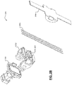
FIG. 1 illustrates a view of a first example electrical connector according to some implementations of the present disclosure; -
FIGS. 2A-2B illustrate views of a second example electrical connector according to some implementations of the present disclosure; and -
FIG. 3 illustrates a view of a third example electrical connector according to some implementations of the present disclosure. - Referring now to
FIG. 1 , a first exampleelectrical connector 100 according to the principles of the present disclosure is illustrated. Theconnector 100 comprises ahousing 104 defining anouter surface 108. Thehousing 104 has at least a portion of awire cable 112 disposed therein. While a flat or band-type wire cable is illustrated, it will be appreciated that a single wire or other type of wire cable (e.g., a round wire cable) could be utilized. One end of thewire cable 112 is electrically connected to another electrical system or a correspondingelectrical connector 116 by connecting one end of thehousing 104 to the correspondingelectrical connector 116 using connector position assurance (CPA) features 120, 124. As shown, this could include aclip 120 that connects to a complimentaryother CPA feature 124. Theconnector 100 also comprises arobotic installation feature 128 at least temporarily attached to or defined in itsouter surface 108. Thisrobotic installation feature 128 could be temporarily and thus removable or detachable after robotic installation. Alternatively, therobotic installation feature 128 could be a permanent feature, which could be interacted multiple times (e.g., for robotic installation and subsequent robotic removal and re-installation). - The
robotic installation feature 128 is configured to be interacted with by anend effector 136 of arobotic installer 132. In the illustrated configuration, theend effector 136 comprises twomembers slot 144 defined by the robotic installation feature. In the illustrated example, theslot 144 defines an equal armed cross shape (also commonly referred to as a plus sign (+) shape), but it will be appreciated that other slot shaped and end effector configurations could be utilized. Therobotic installation feature 128 also defines anouter shape 148 that could be predefined and thus easily identifiable by a basic scanning system (not shown) of therobotic installer 132. In the illustrated example, theouter shape 148 is a hexagonal shape, but it will be appreciated that other shapes could be utilized. In the illustrated example, the twomembers end effector 136 are inserted into theslot 144 and then expanded along one of twoaxes members electrical connector 100. This movable control is obtained by the expansive force maintained by themembers slot 144. The equal armed cross shape configuration of theslot 144 and the movability of themembers different axes electrical connector 100. In one example implementation, there are channels extending from theslot 144 under the top surface of therobotic installation feature 128 and themembers - Referring now to
FIGS. 2A-2B , a second exampleelectrical connector 200 according to the principles of the present disclosure is illustrated. Theelectrical connector 200 is configured to electrically connect twowire cables type wire cables connector 200, it will be appreciated that single or multiple unshielded round-type wire cables could be utilized. Afirst member 208 interlocks with asecond member 212 to thereby secure and electrically connect thewire cables second member 212 also comprises arobotic installation feature 216, which defines aslot 220 that can be interacted with by anend effector 224 of therobotic installer 132. While the samerobotic installer 132 fromFIG. 1 is referenced, it will be appreciated that a different robotic installer could be utilized for this type ofconnector 200. Theend effector 224 could also be the same as or similar to theend effector 136 ofFIG. 1 . In the illustrated example, theslot 220 defines four opposing base channels orslots 228. Thus, when two or more members (not shown) of theend effector 224 are inserted into theslot 220, they could be expanded through two or more of thesebase slots 228 to gain movable control of theelectrical connector 200. Therobotic installation feature 216 can also define a predefined outer shape (e.g.,hexagonal shape 232 as shown) for easy identification by therobotic installer 132. In one example implementation, the two or more members of theend effector 224 each define an L-shape such that their distal ends can engage thebase slots 228. - Referring now to
FIG. 3 , a third exampleelectrical connector 300 is illustrated. Theelectrical connector 300 comprises many of the same or similar components as illustrated inFIG. 1 and as described in greater detail above. Thisconnector 300, however, comprises a differentrobotic installation feature 304. In this illustrated example, anend effector 308 of therobotic installer 132 comprises a gripping or grasping member 312 (e.g., a clamp) that is configured to grip or grasp an X-shaped gripping orgrasping feature 316 that is attached to theouter surface 108 of theconnector 300 via abase member 320 and ashaft 324. While an X-type shape is shown for the gripping or grasping feature is illustrated, it will be appreciated that other shapes could be utilized (a round bar, a flat bar, a circular disc, an equal armed cross shape, a t-shape, etc.). Similarly, whilekeyhole slots 328 are shown for coupling or attaching theshaft 324 to thebase member 320 and to theouter surface 108 of theconnector 300, it will be appreciated that other attachment configurations and/or other shaft configurations could be utilized. - Methods for robotic installation of the
connectors - Example embodiments are provided so that this disclosure will be thorough, and will fully convey the scope to those who are skilled in the art. Numerous specific details are set forth such as examples of specific components, devices, and methods, to provide a thorough understanding of embodiments of the present disclosure. It will be apparent to those skilled in the art that specific details need not be employed, that example embodiments may be embodied in many different forms and that neither should be construed to limit the scope of the disclosure. In some example embodiments, well-known procedures, well-known device structures, and well-known technologies are not described in detail.
- The terminology used herein is for the purpose of describing particular example embodiments only and is not intended to be limiting. As used herein, the singular forms "a," "an," and "the" may be intended to include the plural forms as well, unless the context clearly indicates otherwise. The term "and/or" includes any and all combinations of one or more of the associated listed items. The terms "comprises," "comprising," "including," and "having," are inclusive and therefore specify the presence of stated features, integers, steps, operations, elements, and/or components, but do not preclude the presence or addition of one or more other features, integers, steps, operations, elements, components, and/or groups thereof. The method steps, processes, and operations described herein are not to be construed as necessarily requiring their performance in the particular order discussed or illustrated, unless specifically identified as an order of performance. It is also to be understood that additional or alternative steps may be employed.
- Although the terms first, second, third, etc. may be used herein to describe various elements, components, regions, layers and/or sections, these elements, components, regions, layers and/or sections should not be limited by these terms. These terms may be only used to distinguish one element, component, region, layer or section from another region, layer or section. Terms such as "first," "second," and other numerical terms when used herein do not imply a sequence or order unless clearly indicated by the context. Thus, a first element, component, region, layer or section discussed below could be termed a second element, component, region, layer or section without departing from the teachings of the example embodiments.
- As used herein, the term module may refer to, be part of, or include: an Application Specific Integrated Circuit (ASIC); an electronic circuit; a combinational logic circuit; a field programmable gate array (FPGA); a processor or a distributed network of processors (shared, dedicated, or grouped) and storage in networked clusters or datacenters that executes code or a process; other suitable components that provide the described functionality; or a combination of some or all of the above, such as in a system-on-chip. The term module may also include memory (shared, dedicated, or grouped) that stores code executed by the one or more processors.
- The term code, as used above, may include software, firmware, byte-code and/or microcode, and may refer to programs, routines, functions, classes, and/or objects. The term shared, as used above, means that some or all code from multiple modules may be executed using a single (shared) processor. In addition, some or all code from multiple modules may be stored by a single (shared) memory. The term group, as used above, means that some or all code from a single module may be executed using a group of processors. In addition, some or all code from a single module may be stored using a group of memories.
- The techniques described herein may be implemented by one or more computer programs executed by one or more processors. The computer programs include processor-executable instructions that are stored on a non-transitory tangible computer readable medium. The computer programs may also include stored data. Non-limiting examples of the non-transitory tangible computer readable medium are nonvolatile memory, magnetic storage, and optical storage.
- Some portions of the above description present the techniques described herein in terms of algorithms and symbolic representations of operations on information. These algorithmic descriptions and representations are the means used by those skilled in the data processing arts to most effectively convey the substance of their work to others skilled in the art. These operations, while described functionally or logically, are understood to be implemented by computer programs. Furthermore, it has also proven convenient at times to refer to these arrangements of operations as modules or by functional names, without loss of generality.
- Unless specifically stated otherwise as apparent from the above discussion, it is appreciated that throughout the description, discussions utilizing terms such as "processing" or "computing" or "calculating" or "determining" or "displaying" or the like, refer to the action and processes of a computer system, or similar electronic computing device, that manipulates and transforms data represented as physical (electronic) quantities within the computer system memories or registers or other such information storage, transmission or display devices.
- Certain aspects of the described techniques include process steps and instructions described herein in the form of an algorithm. It should be noted that the described process steps and instructions could be embodied in software, firmware or hardware, and when embodied in software, could be downloaded to reside on and be operated from different platforms used by real time network operating systems.
- The present disclosure also relates to an apparatus for performing the operations herein. This apparatus may be specially constructed for the required purposes, or it may comprise a general-purpose computer selectively activated or reconfigured by a computer program stored on a computer readable medium that can be accessed by the computer. Such a computer program may be stored in a tangible computer readable storage medium, such as, but is not limited to, any type of disk including floppy disks, optical disks, CD-ROMs, magnetic-optical disks, read-only memories (ROMs), random access memories (RAMs), EPROMs, EEPROMs, magnetic or optical cards, application specific integrated circuits (ASICs), or any type of media suitable for storing electronic instructions, and each coupled to a computer system bus. Furthermore, the computers referred to in the specification may include a single processor or may be architectures employing multiple processor designs for increased computing capability.
- The algorithms and operations presented herein are not inherently related to any particular computer or other apparatus. Various general-purpose systems may also be used with programs in accordance with the teachings herein, or it may prove convenient to construct more specialized apparatuses to perform the required method steps. The required structure for a variety of these systems will be apparent to those of skill in the art, along with equivalent variations. In addition, the present disclosure is not described with reference to any particular programming language. It is appreciated that a variety of programming languages may be used to implement the teachings of the present disclosure as described herein, and any references to specific languages are provided for disclosure of enablement and best mode of the present invention.
- The present disclosure is well suited to a wide variety of computer network systems over numerous topologies. Within this field, the configuration and management of large networks comprise storage devices and computers that are communicatively coupled to dissimilar computers and storage devices over a network, such as the Internet.
- The foregoing description of the embodiments has been provided for purposes of illustration and description. It is not intended to be exhaustive or to limit the disclosure. Individual elements or features of a particular embodiment are generally not limited to that particular embodiment, but, where applicable, are interchangeable and can be used in a selected embodiment, even if not specifically shown or described. The same may also be varied in many ways. Such variations are not to be regarded as a departure from the disclosure, and all such modifications are intended to be included within the scope of the disclosure.
Claims (15)
- An electrical connector, comprising:a housing defining an outer surface;a wire cable at least partially disposed in the housing; anda robotic installation feature at least temporarily attached to or defined in the outer surface of the housing, wherein the robotic installation feature defines a slot that is configured to be interacted with by an end effector of a robotic installer during robotic installation of the electrical connector with a corresponding electrical connector.
- The electrical connector of claim 1, wherein the slot defines an equal armed cross shape.
- The electrical connector of claim 2, wherein the end effector of the robotic installer comprises two members configured to be inserted into the slot and expanded along one of two axes to thereby fix the two members therein and obtain movable control of the electrical connector.
- The electrical connector of claim 3, wherein the two axes are perpendicular to each other to provide for both horizontal and vertical robotic installation of the electrical connector.
- The electrical connector of claim 2, wherein the robotic installation feature defines a predefined hexagonal outer shape such that it is identifiable by the robotic installer.
- The electrical connector of claim 1, wherein the slot defines a hexagonal shape and at least two opposing base slots.
- The electrical connector of claim 6, wherein the end effector comprises at least two members configured to be inserted into the slot and expanded through at least two of the at least two opposing base slots to thereby fix the at least two members therein and obtain movable control of the electrical connector.
- The electrical connector of claim 7, wherein the slot defines four opposing base slots.
- A method of using a robotic installer to install an electrical connector, the method comprising:identifying, by the robotic installer, a robotic installation feature at least temporarily attached to or defined in an outer surface of a housing of the electrical connector;inserting, by the robotic installer, at least two members of an end effector of the robotic installer into a slot defined by the robotic installation feature;expanding, by the robotic installer, the at least two members of the end effector along at least one of two axes to thereby fix the at least two members therein and obtain movable control of the electrical connector; andinstalling, by the robotic installer, the electrical connector with a corresponding electrical connector.
- The method of claim 9, wherein installing the electrical connector with another electrical system includes engaging the electrical connector with a connector position assurance (CPA) feature of the corresponding electrical connector.
- The method of claim 10, further comprising upon engaging the electrical connector with the CPA feature of the corresponding electrical connector:retracting, by the robotic installer, the two members of the end effector along the one of the two axes; andremoving, by the robotic installer, the two members of the end effector from the slot.
- The method of claim 11, wherein the slot defines an equal armed cross shape the two axes are perpendicular to each other to provide for both horizontal and vertical robotic installation of the electrical connector.
- The method of claim 11, wherein the robotic installation feature defines a predefined hexagonal outer shape such that it is identifiable by the robotic installer.
- The method of claim 11, wherein the slot defines a hexagonal shape and at least two opposing base slots.
- The method of claim 14, wherein the at least two members of the end effector are inserted into the slot and expanded through at least two of the at least two opposing base slots to thereby fix the at least two members therein and obtain movable control of the electrical connector.
Applications Claiming Priority (2)
| Application Number | Priority Date | Filing Date | Title |
|---|---|---|---|
| US202062956848P | 2020-01-03 | 2020-01-03 | |
| US17/118,708 US11888262B2 (en) | 2020-01-03 | 2020-12-11 | Automotive electrical connector features for robotic installation |
Publications (1)
| Publication Number | Publication Date |
|---|---|
| EP3846296A1 true EP3846296A1 (en) | 2021-07-07 |
Family
ID=73856955
Family Applications (1)
| Application Number | Title | Priority Date | Filing Date |
|---|---|---|---|
| EP20216775.5A Pending EP3846296A1 (en) | 2020-01-03 | 2020-12-23 | Electrical connector having a slot for robotic installation and method of using a robotic installer to install an electrical connector |
Country Status (3)
| Country | Link |
|---|---|
| US (1) | US11888262B2 (en) |
| EP (1) | EP3846296A1 (en) |
| CN (1) | CN113161785A (en) |
Citations (3)
| Publication number | Priority date | Publication date | Assignee | Title |
|---|---|---|---|---|
| EP1488893A2 (en) * | 2003-06-17 | 2004-12-22 | Fanuc Ltd | Connector gripping device, connector inspection system comprising the device, and connector connection system |
| US20150162693A1 (en) * | 2013-12-06 | 2015-06-11 | J.S.T. Corporation | Multi-directional wiring routing device and method of operating the same |
| US10205266B1 (en) * | 2017-10-30 | 2019-02-12 | Aptiv Technologies Limited | Connector wire dress cover for robotic installation |
Family Cites Families (19)
| Publication number | Priority date | Publication date | Assignee | Title |
|---|---|---|---|---|
| US4664588A (en) * | 1984-03-09 | 1987-05-12 | Applied Robotics Inc. | Apparatus and method for connecting and exchanging remote manipulable elements to a central control source |
| TW353545U (en) * | 1997-06-10 | 1999-02-21 | Hon Hai Prec Ind Co Ltd | Connector with auxiliary assembling apparatus |
| US6116949A (en) * | 1999-01-13 | 2000-09-12 | The Whitaker Corporation | Electrostatic protection cover for electrical connector |
| JP2003132983A (en) * | 2001-10-22 | 2003-05-09 | Yazaki Corp | Combination lamp connection structure |
| US6655970B2 (en) * | 2002-03-18 | 2003-12-02 | Tien-Ching Tsai | Connecting socket and terminal structure thereof |
| TW585351U (en) * | 2003-06-06 | 2004-04-21 | Hon Hai Prec Ind Co Ltd | Electrical connector assembly |
| TWM249243U (en) * | 2003-07-18 | 2004-11-01 | Hon Hai Prec Ind Co Ltd | Electrical connector assembly |
| US9586327B2 (en) * | 2005-12-20 | 2017-03-07 | Intuitive Surgical Operations, Inc. | Hook and pivot electro-mechanical interface for robotic medical arms |
| US7762825B2 (en) * | 2005-12-20 | 2010-07-27 | Intuitive Surgical Operations, Inc. | Electro-mechanical interfaces to mount robotic surgical arms |
| US7182620B1 (en) * | 2006-04-12 | 2007-02-27 | Lotes Co., Ltd. | Buckling structure and an electrical connector element using the same |
| US8142200B2 (en) * | 2007-03-26 | 2012-03-27 | Liposonix, Inc. | Slip ring spacer and method for its use |
| US8675820B2 (en) * | 2010-08-10 | 2014-03-18 | Varian Medical Systems, Inc. | Electronic conical collimator verification |
| TWM408851U (en) * | 2010-12-16 | 2011-08-01 | Hon Hai Prec Ind Co Ltd | Electrical connector assembly |
| US9826445B2 (en) * | 2015-05-21 | 2017-11-21 | At&T Mobility Ii Llc | Facilitation of adaptive dejitter buffer between mobile devices |
| US10034716B2 (en) * | 2015-09-14 | 2018-07-31 | Globus Medical, Inc. | Surgical robotic systems and methods thereof |
| EP3421172B1 (en) * | 2016-02-26 | 2020-02-19 | Fuji Corporation | Robot arm control system |
| KR102339489B1 (en) * | 2017-04-07 | 2021-12-17 | 리씽크 로보틱스 게엠베하 | Quick release mechanism for tool adapter plate and robot comprising same |
| CN206646784U (en) * | 2017-04-10 | 2017-11-17 | 张宝娟 | A kind of ceramic tile mounting bracket of house ornamentation |
| US10355409B2 (en) | 2017-06-27 | 2019-07-16 | Aptiv Technologies Limited | Wiring-harness with connector staging device |
-
2020
- 2020-12-11 US US17/118,708 patent/US11888262B2/en active Active
- 2020-12-23 EP EP20216775.5A patent/EP3846296A1/en active Pending
- 2020-12-31 CN CN202011618388.3A patent/CN113161785A/en active Pending
Patent Citations (3)
| Publication number | Priority date | Publication date | Assignee | Title |
|---|---|---|---|---|
| EP1488893A2 (en) * | 2003-06-17 | 2004-12-22 | Fanuc Ltd | Connector gripping device, connector inspection system comprising the device, and connector connection system |
| US20150162693A1 (en) * | 2013-12-06 | 2015-06-11 | J.S.T. Corporation | Multi-directional wiring routing device and method of operating the same |
| US10205266B1 (en) * | 2017-10-30 | 2019-02-12 | Aptiv Technologies Limited | Connector wire dress cover for robotic installation |
Also Published As
| Publication number | Publication date |
|---|---|
| US20210210905A1 (en) | 2021-07-08 |
| CN113161785A (en) | 2021-07-23 |
| US11888262B2 (en) | 2024-01-30 |
Similar Documents
| Publication | Publication Date | Title |
|---|---|---|
| US11523530B2 (en) | Self-aligning mechanical mount and electrical connection system for electronic modules with features for robotic assembly | |
| US10074914B2 (en) | Plug connector | |
| JP6279224B2 (en) | Electrical crimp contact device | |
| JP4571154B2 (en) | Airtight electrical connector parts | |
| US10477717B2 (en) | Self-aligning busbar assembly | |
| US20200358230A1 (en) | Methods and systems for a modular plug-in bus wiring system | |
| US11515660B2 (en) | Electrical connector assembly with retaining device | |
| US11183793B2 (en) | Connector system with a terminal retaining device having a reverse hinged lock feature | |
| US20220329008A1 (en) | Electrical plug connector, electrical plug connection and securing element for an electrical plug connector | |
| US12407122B2 (en) | Direct device electrical connection to flexible circuits or other conductors | |
| EP2955797A1 (en) | Cable strain relief | |
| KR20190078874A (en) | Heater for Shrink Tube | |
| US11888262B2 (en) | Automotive electrical connector features for robotic installation | |
| EP3893337A1 (en) | Electrical connector system | |
| US11545806B2 (en) | Conductor assembly staging for robotic installation | |
| CN109256990B (en) | Motor control method and device | |
| AU2022209270A1 (en) | Patch panel arrangements cable terminating devices & methods | |
| CN113206397B (en) | Terminal wire clip | |
| US7275952B1 (en) | Hinged electrical connector | |
| US10832875B2 (en) | Barrier usable with electrical interruption device and structured to resist the insertion of probe having known dimensions | |
| US10476207B2 (en) | Electrical distribution assembly | |
| US10958031B1 (en) | Terminal un-seated tester for smart kitting of wired connectors | |
| US9293803B1 (en) | Internally fittable and removable mount for external antenna | |
| CN115799869A (en) | Direct equipment electrical connection to flex circuits or other conductors | |
| US20230130455A1 (en) | Automated wire kitting systems and methods |
Legal Events
| Date | Code | Title | Description |
|---|---|---|---|
| PUAI | Public reference made under article 153(3) epc to a published international application that has entered the european phase |
Free format text: ORIGINAL CODE: 0009012 |
|
| STAA | Information on the status of an ep patent application or granted ep patent |
Free format text: STATUS: THE APPLICATION HAS BEEN PUBLISHED |
|
| AK | Designated contracting states |
Kind code of ref document: A1 Designated state(s): AL AT BE BG CH CY CZ DE DK EE ES FI FR GB GR HR HU IE IS IT LI LT LU LV MC MK MT NL NO PL PT RO RS SE SI SK SM TR |
|
| STAA | Information on the status of an ep patent application or granted ep patent |
Free format text: STATUS: REQUEST FOR EXAMINATION WAS MADE |
|
| 17P | Request for examination filed |
Effective date: 20220107 |
|
| RBV | Designated contracting states (corrected) |
Designated state(s): AL AT BE BG CH CY CZ DE DK EE ES FI FR GB GR HR HU IE IS IT LI LT LU LV MC MK MT NL NO PL PT RO RS SE SI SK SM TR |
|
| STAA | Information on the status of an ep patent application or granted ep patent |
Free format text: STATUS: EXAMINATION IS IN PROGRESS |
|
| 17Q | First examination report despatched |
Effective date: 20230120 |
|
| RAP3 | Party data changed (applicant data changed or rights of an application transferred) |
Owner name: APTIV TECHNOLOGIES LIMITED |
|
| RAP1 | Party data changed (applicant data changed or rights of an application transferred) |
Owner name: APTIV TECHNOLOGIES AG |
|
| RAP3 | Party data changed (applicant data changed or rights of an application transferred) |
Owner name: APTIV TECHNOLOGIES AG |