EP3846294A1 - Terminal assembly for a charging connector including an improved thermal monitoring - Google Patents
Terminal assembly for a charging connector including an improved thermal monitoring Download PDFInfo
- Publication number
- EP3846294A1 EP3846294A1 EP20150115.2A EP20150115A EP3846294A1 EP 3846294 A1 EP3846294 A1 EP 3846294A1 EP 20150115 A EP20150115 A EP 20150115A EP 3846294 A1 EP3846294 A1 EP 3846294A1
- Authority
- EP
- European Patent Office
- Prior art keywords
- interface material
- thermal
- thermal interface
- terminals
- terminal
- Prior art date
- Legal status (The legal status is an assumption and is not a legal conclusion. Google has not performed a legal analysis and makes no representation as to the accuracy of the status listed.)
- Granted
Links
Images


Classifications
-
- H—ELECTRICITY
- H01—ELECTRIC ELEMENTS
- H01R—ELECTRICALLY-CONDUCTIVE CONNECTIONS; STRUCTURAL ASSOCIATIONS OF A PLURALITY OF MUTUALLY-INSULATED ELECTRICAL CONNECTING ELEMENTS; COUPLING DEVICES; CURRENT COLLECTORS
- H01R13/00—Details of coupling devices of the kinds covered by groups H01R12/70 or H01R24/00 - H01R33/00
- H01R13/66—Structural association with built-in electrical component
- H01R13/665—Structural association with built-in electrical component with built-in electronic circuit
- H01R13/6683—Structural association with built-in electrical component with built-in electronic circuit with built-in sensor
-
- B—PERFORMING OPERATIONS; TRANSPORTING
- B60—VEHICLES IN GENERAL
- B60L—PROPULSION OF ELECTRICALLY-PROPELLED VEHICLES; SUPPLYING ELECTRIC POWER FOR AUXILIARY EQUIPMENT OF ELECTRICALLY-PROPELLED VEHICLES; ELECTRODYNAMIC BRAKE SYSTEMS FOR VEHICLES IN GENERAL; MAGNETIC SUSPENSION OR LEVITATION FOR VEHICLES; MONITORING OPERATING VARIABLES OF ELECTRICALLY-PROPELLED VEHICLES; ELECTRIC SAFETY DEVICES FOR ELECTRICALLY-PROPELLED VEHICLES
- B60L53/00—Methods of charging batteries, specially adapted for electric vehicles; Charging stations or on-board charging equipment therefor; Exchange of energy storage elements in electric vehicles
- B60L53/10—Methods of charging batteries, specially adapted for electric vehicles; Charging stations or on-board charging equipment therefor; Exchange of energy storage elements in electric vehicles characterised by the energy transfer between the charging station and the vehicle
- B60L53/14—Conductive energy transfer
- B60L53/16—Connectors, e.g. plugs or sockets, specially adapted for charging electric vehicles
-
- G—PHYSICS
- G01—MEASURING; TESTING
- G01K—MEASURING TEMPERATURE; MEASURING QUANTITY OF HEAT; THERMALLY-SENSITIVE ELEMENTS NOT OTHERWISE PROVIDED FOR
- G01K1/00—Details of thermometers not specially adapted for particular types of thermometer
- G01K1/02—Means for indicating or recording specially adapted for thermometers
- G01K1/026—Means for indicating or recording specially adapted for thermometers arrangements for monitoring a plurality of temperatures, e.g. by multiplexing
-
- G—PHYSICS
- G01—MEASURING; TESTING
- G01K—MEASURING TEMPERATURE; MEASURING QUANTITY OF HEAT; THERMALLY-SENSITIVE ELEMENTS NOT OTHERWISE PROVIDED FOR
- G01K1/00—Details of thermometers not specially adapted for particular types of thermometer
- G01K1/14—Supports; Fastening devices; Arrangements for mounting thermometers in particular locations
- G01K1/143—Supports; Fastening devices; Arrangements for mounting thermometers in particular locations for measuring surface temperatures
-
- G—PHYSICS
- G01—MEASURING; TESTING
- G01K—MEASURING TEMPERATURE; MEASURING QUANTITY OF HEAT; THERMALLY-SENSITIVE ELEMENTS NOT OTHERWISE PROVIDED FOR
- G01K1/00—Details of thermometers not specially adapted for particular types of thermometer
- G01K1/16—Special arrangements for conducting heat from the object to the sensitive element
-
- H—ELECTRICITY
- H01—ELECTRIC ELEMENTS
- H01R—ELECTRICALLY-CONDUCTIVE CONNECTIONS; STRUCTURAL ASSOCIATIONS OF A PLURALITY OF MUTUALLY-INSULATED ELECTRICAL CONNECTING ELEMENTS; COUPLING DEVICES; CURRENT COLLECTORS
- H01R13/00—Details of coupling devices of the kinds covered by groups H01R12/70 or H01R24/00 - H01R33/00
- H01R13/66—Structural association with built-in electrical component
- H01R13/70—Structural association with built-in electrical component with built-in switch
- H01R13/713—Structural association with built-in electrical component with built-in switch the switch being a safety switch
- H01R13/7137—Structural association with built-in electrical component with built-in switch the switch being a safety switch with thermal interrupter
-
- H—ELECTRICITY
- H01—ELECTRIC ELEMENTS
- H01R—ELECTRICALLY-CONDUCTIVE CONNECTIONS; STRUCTURAL ASSOCIATIONS OF A PLURALITY OF MUTUALLY-INSULATED ELECTRICAL CONNECTING ELEMENTS; COUPLING DEVICES; CURRENT COLLECTORS
- H01R13/00—Details of coupling devices of the kinds covered by groups H01R12/70 or H01R24/00 - H01R33/00
- H01R13/66—Structural association with built-in electrical component
- H01R13/665—Structural association with built-in electrical component with built-in electronic circuit
- H01R13/6658—Structural association with built-in electrical component with built-in electronic circuit on printed circuit board
-
- H—ELECTRICITY
- H01—ELECTRIC ELEMENTS
- H01R—ELECTRICALLY-CONDUCTIVE CONNECTIONS; STRUCTURAL ASSOCIATIONS OF A PLURALITY OF MUTUALLY-INSULATED ELECTRICAL CONNECTING ELEMENTS; COUPLING DEVICES; CURRENT COLLECTORS
- H01R2103/00—Two poles
-
- H—ELECTRICITY
- H01—ELECTRIC ELEMENTS
- H01R—ELECTRICALLY-CONDUCTIVE CONNECTIONS; STRUCTURAL ASSOCIATIONS OF A PLURALITY OF MUTUALLY-INSULATED ELECTRICAL CONNECTING ELEMENTS; COUPLING DEVICES; CURRENT COLLECTORS
- H01R2107/00—Four or more poles
-
- H—ELECTRICITY
- H01—ELECTRIC ELEMENTS
- H01R—ELECTRICALLY-CONDUCTIVE CONNECTIONS; STRUCTURAL ASSOCIATIONS OF A PLURALITY OF MUTUALLY-INSULATED ELECTRICAL CONNECTING ELEMENTS; COUPLING DEVICES; CURRENT COLLECTORS
- H01R24/00—Two-part coupling devices, or either of their cooperating parts, characterised by their overall structure
- H01R24/28—Coupling parts carrying pins, blades or analogous contacts and secured only to wire or cable
- H01R24/30—Coupling parts carrying pins, blades or analogous contacts and secured only to wire or cable with additional earth or shield contacts
-
- Y—GENERAL TAGGING OF NEW TECHNOLOGICAL DEVELOPMENTS; GENERAL TAGGING OF CROSS-SECTIONAL TECHNOLOGIES SPANNING OVER SEVERAL SECTIONS OF THE IPC; TECHNICAL SUBJECTS COVERED BY FORMER USPC CROSS-REFERENCE ART COLLECTIONS [XRACs] AND DIGESTS
- Y02—TECHNOLOGIES OR APPLICATIONS FOR MITIGATION OR ADAPTATION AGAINST CLIMATE CHANGE
- Y02T—CLIMATE CHANGE MITIGATION TECHNOLOGIES RELATED TO TRANSPORTATION
- Y02T10/00—Road transport of goods or passengers
- Y02T10/60—Other road transportation technologies with climate change mitigation effect
- Y02T10/70—Energy storage systems for electromobility, e.g. batteries
-
- Y—GENERAL TAGGING OF NEW TECHNOLOGICAL DEVELOPMENTS; GENERAL TAGGING OF CROSS-SECTIONAL TECHNOLOGIES SPANNING OVER SEVERAL SECTIONS OF THE IPC; TECHNICAL SUBJECTS COVERED BY FORMER USPC CROSS-REFERENCE ART COLLECTIONS [XRACs] AND DIGESTS
- Y02—TECHNOLOGIES OR APPLICATIONS FOR MITIGATION OR ADAPTATION AGAINST CLIMATE CHANGE
- Y02T—CLIMATE CHANGE MITIGATION TECHNOLOGIES RELATED TO TRANSPORTATION
- Y02T10/00—Road transport of goods or passengers
- Y02T10/60—Other road transportation technologies with climate change mitigation effect
- Y02T10/7072—Electromobility specific charging systems or methods for batteries, ultracapacitors, supercapacitors or double-layer capacitors
-
- Y—GENERAL TAGGING OF NEW TECHNOLOGICAL DEVELOPMENTS; GENERAL TAGGING OF CROSS-SECTIONAL TECHNOLOGIES SPANNING OVER SEVERAL SECTIONS OF THE IPC; TECHNICAL SUBJECTS COVERED BY FORMER USPC CROSS-REFERENCE ART COLLECTIONS [XRACs] AND DIGESTS
- Y02—TECHNOLOGIES OR APPLICATIONS FOR MITIGATION OR ADAPTATION AGAINST CLIMATE CHANGE
- Y02T—CLIMATE CHANGE MITIGATION TECHNOLOGIES RELATED TO TRANSPORTATION
- Y02T90/00—Enabling technologies or technologies with a potential or indirect contribution to GHG emissions mitigation
- Y02T90/10—Technologies relating to charging of electric vehicles
- Y02T90/14—Plug-in electric vehicles
Definitions
- the present disclosure relates to a terminal assembly for a charging connector intended for connection to a mating charging connector, including an improved thermal monitoring, and a method for manufacturing such a terminal assembly.
- a charging connector can be a charging socket or a charging plug. It can be used in particular for charging a motor vehicle driven by an electric motor. Such a vehicle is referred as an "electric vehicle" in the present disclosure.
- a charging connector of this type is designed to transmit high charging currents, which may result in a high thermal power dissipation. For safety reasons, it is required to monitor the temperature of the charging connector in order to detect any overheating. In case that an important rise of temperature of the charging connector is detected, the charging current can be reduced or even switched off.
- EP 3 286 804 A1 discloses a plug-in connector part, also referred as a charging connector, comprising a temperature monitoring device having a support element, that can be formed as a printed circuit board, and a thermal sensor (or thermistor) mounted on the support element.
- the support element is provided with at least one opening through which an electrical contact element for transmitting electrical current (also called a "terminal” or “pin") extends.
- a metal contact surface is arranged at the opening so that the terminal is thermally coupled to the contact surface.
- a coupling portion is used to thermally couple the thermal sensor with the opening and therefore with the terminal extending through the opening.
- the coupling portion is connected to the metal contact surface and extends over the entire surface of the temperature-monitoring device, inside the support element.
- the present disclosure concerns a terminal assembly for a charging connector, comprising
- Such a configuration of the terminal assembly allows to monitor the temperature of the terminal(s) and quickly detect an excessive rise in temperature, in order to take appropriate countermeasures, for example reducing the charging current or switching off the charging current.
- the heat generated by each terminal flows rapidly from the terminal to a corresponding thermal sensor through the thermal interface material in which the sensor is immersed.
- the terminal assembly can comprise a housing element for holding the N terminals and each of the M thermal sensors is immersed in the thermal interface material filling a container provided by an inner surface of a hole in the housing element, the first surface of the support element and said corresponding contact surface.
- said corresponding contact surface is formed by a surface area of said corresponding terminal.
- said hole in the housing element is a through hole and the corresponding contact surface of the terminal is surrounded by an edge of an opening of the through hole.
- each of the M thermal sensors is disposed in front of said surface area of the corresponding terminal forming said corresponding contact surface. This allows a heat transfer in straight line from the terminal to the corresponding thermal sensor.
- the thermal interface material filling said container can comprise a first layer in contact with said corresponding contact surface and a second layer in contact with the first surface of the support element, and the inner surface of the hole is configured so that the second layer is larger than the first layer.
- said corresponding contact surface is part of a lamella metal spring that is in contact with said corresponding terminal.
- the lamella metal spring can comprise a body part that is sandwiched between the thermal interface material and a surface at a bottom of said hole in the housing element, and an arm part that extends from the body part towards an end part that is in contact with the corresponding terminal.
- the arm part of the lamella metal spring is in contact with the thermal interface material.
- the arm part has a surface that is in contact with the thermal interface material.
- the thermal conductivity of the thermal interface material is advantageously equal with or superior to 1 W / m-K.
- the number N of terminals is advantageously equal to the number M of thermal sensors.
- the terminal assembly can comprise a plurality of N terminals for transmitting the charging current and the temperature monitoring device can comprise N respective thermal sensors that are immersed in the thermal interface material.
- the thermal interface material fills N containers provided by the inner surface of N respective holes, N contact surfaces that are respectively thermally coupled with the N terminals and the first surface of the support element.
- the present disclosure also concerns:
- a method for manufacturing a terminal assembly for a charging connector comprising the steps of
- the method can comprise, prior to the step of dispensing the thermal interface material, a step of assembling the N terminals and the housing element, wherein said respective contact surfaces are formed by respective surface areas of the M terminals and, in the step of dispensing, the thermal interface material is dispensed on said respective contact surfaces through holes in the housing element.
- the method can comprise, prior to the step of dispensing the thermal interface material, a step of mounting M lamella metal springs into holes in the housing element and, after the steps of dispensing the thermal interface material and immersing the M thermal sensors in said thermal interface material, a step of assembling the N terminals and the housing element, wherein, in the step of dispensing, the thermal interface material covers a surface of each of the M lamella metal springs, and wherein, in the step of assembling the N terminals and the housing element, each of the M lamella metal springs is put in contact with a corresponding terminal.
- a vehicle driven by an electric motor also referred as an electric vehicle, comprises electric batteries to supply electrical power to the electric motor.
- the electric batteries can be electrically charged at a charging station.
- the vehicle can be connected to the charging station with a charging cable having two charging plugs at both ends.
- the first charging plug of the charging cable is plugged into a charging connector in the form of a charging socket on the vehicle, also referred as a "charging inlet”.
- the second charging plug of the charging cable is plugged into a charging connector in the form of a charging socket on the charging station, also referred as a "charging outlet”.
- charging connector may refer to a charging inlet on a vehicle, or a charging outlet on a charging station, or a charging plug on a charging cable.
- the charging connector may be used to charge electric devices other than electric vehicle.
- a charging connector has a terminal assembly.
- the terminal assembly has a number of N terminals for transmitting a charging current, with N ⁇ 1, and a temperature monitoring device.
- the terminal assembly has also a housing element for holding the N terminals.
- a terminal may also be referred as a "pin” or a "contact element".
- the function of a terminal is to transmit a charging current. Since the charging currents can be high, the temperature of a terminal may rise and cause an overheating of the components of the charging connector. Therefore, it is necessary to monitor the temperature of the N terminals and to be able to quickly detect an excessive rise in temperature of at least one terminal, in order to reduce or switch off the charging current before any damage to the components.
- the temperature monitoring device performs temperature monitoring in order to detect an excessive rise in temperature of one or more terminals and, if an excessive rise of temperature is detected, the charging current can be reduced or switched off.
- the temperature monitoring device has a support element and M thermal sensors, with M ⁇ 1, for monitoring the temperature of the N terminals.
- the M thermal sensors are mounted on a first surface of the support element.
- the support element is for example a printed circuit board.
- the N terminals and the temperature monitoring device are assembled with the housing element.
- the housing element has one or more holes for receiving a thermal interface material.
- a thermal interface material is a material that is usually inserted between two components in order to enhance the thermal coupling between them.
- the thermal interface material is thermally conductive.
- the thermal conductivity of the thermal interface material is advantageously equal with or superior to 1 W / m-K. It can be a liquid dispensed material that will cure at room temperature or with the addition of heat.
- the thermal interface material can be a liquid gap filling material, for example the product referenced as "BERGQUIST® GAP FILLER TGF 4000" manufactured by Henkel company.
- the thermal interface material is an electrically insulating material, advantageously a dielectric material.
- Each of the M thermal sensors is immersed in the thermal interface material that fills a space between the first surface of the support element and a corresponding contact surface that is thermally coupled with a corresponding terminal (of the N terminals). In this way, said thermal sensor and the corresponding terminal are thermally coupled by the thermal interface material and the corresponding contact surface.
- Each of the M thermal sensors is immersed in the thermal interface material filling a corresponding container. More precisely, said container receiving the thermal sensor is formed by the surfaces including an inner surface of a hole in the housing element, the first surface of the support element, and the corresponding contact surface that is thermally coupled with the corresponding terminal.
- the space filled with the thermal interface material is inside a container made by an inner surface of a hole in the housing element, the first surface of the support element (the one supporting the at least one thermal sensor) and the contact surface.
- each of the M thermal sensors is immersed in the thermal interface material that fills a space between the first surface of the support element and a corresponding contact surface that is thermally coupled with a corresponding terminal (of the N terminals).
- said corresponding contact surface is formed by a surface area of the corresponding terminal.
- this surface area of the corresponding terminal is surrounded by an edge of one opening of a through hole in the housing element.
- said corresponding contact surface is formed by a lamella metal spring that is in contact with the corresponding terminal.
- the number N of terminals is for example equal to the number M of thermal sensors. In such a case, one thermal sensor monitors one terminal.
- the number N of terminals can be two. In case of AC (Alternating Current) charging, the number N of terminals can be four.
- a method for manufacturing a terminal assembly for a charging connector comprises the steps of
- the method comprises a step of dispensing a thermal interface material, in liquid state, in the housing element on respective contact surfaces intended to be thermally coupled with the N terminals.
- the thermal interface material is still in liquid state, the M thermal sensors are immersed in the thermal interface material by putting the support element, which first surface faces downwards, on a top surface of the liquid. Then, the thermal interface material is cured.
- the N terminals and the housing element are assembled prior to the step of dispensing the thermal interface material. Then, in the step of dispensing, the thermal interface material is dispensed on respective contact surfaces, formed by respective surface areas of the M terminals, through holes in the housing element.
- M lamella metal springs are mounted into holes in the housing element, prior to the step of dispensing the thermal interface material.
- the thermal interface material covers a surface of each of the M lamella metal springs.
- the N terminals and the housing element are assembled. In assembling the N terminals and the housing element, each of the M lamella metal springs is put in contact with a corresponding terminal of the M terminals.
- the at least one terminal, the temperature monitoring device and the housing element are assembled in order to form the terminal assembly. Different methods of assembling can be used.
- the terminal assembly and the method for manufacturing the terminal assembly will now be described in more detail with reference to the figures that represent a first and second exemplary embodiments.
- Figures 1A and 1B show a first exemplary embodiment of a terminal assembly 1 for a charging connector, for example the charging connector on the vehicle.
- Figure 1B is analogous to figure 1A but shows some of the structural elements of the terminal assembly 1 of figure 1A in semitransparency, in order to facilitate the understanding of the structure of the terminal assembly 1.
- This terminal assembly 1 of the first exemplary embodiment is suitable for a DC (Direct Current) charging connector.
- the support element 120 can be formed by a printed circuit board that has a first surface 122 on which the two thermal sensors 121 are mounted.
- the printed circuit board 120 is made of an electrically insulating material and supports electrical conducting tracks (non represented).
- the housing element 11 holds the two terminals 10.
- the two terminals extend along two parallel axis and have for example a circular cross section.
- the terminals may have any other shape.
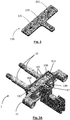
- Each terminal 10 projects from the housing element 11 by means of a first end 10A, and is held by the housing element 11 by means of a shank portion 10B that is next to a second end 10C, opposite to the first end 10A, as shown in figure 4 .
- the second end 10C is intended to make electrical contact with a conductor element of the charging connector integrating the terminal assembly 1.
- the first end 10A is intended to make electrical contact with a conductor element of a mating charging connector to which said charging connector is connected.
- the housing element 11 can be made of a plastic material. It can be over-molded on the two terminals 10.
- the housing element 11 has an insertion part 110, that can be viewed for example in figure 3A , in which the temperature monitoring device 12 is inserted.
- the housing element 11 has two holes 111, that can be viewed in figure 3A . These holes 111 are provided through a bottom wall of the insertion part 110. This bottom wall is over-molded on the shank portions 10B of the two terminals 10. Therefore, each through hole 111 has an opening (the lower opening in figure 3A ) which edge is in contact with the shank portion 10B of the corresponding terminal 10 and surrounds a surface area 100 of the terminal 10. Each hole 111 forms like a window between the terminal 10 (more precisely the surface area 100 of the shank portion 10B) and the inside of the insertion part 110 of the housing element 11.
- the support element 120 has an external shape that fits the inside of the insertion part 110, as shown in figures 1A, 1B and 2 .
- the support element 120 is inserted in the insertion part 110 and disposed at the bottom of the insertion part 110, the first surface of the support element 120 (the one supporting the thermal sensors 121) being oriented towards the bottom of the insertion part 110.
- the housing element 11 has a plurality of fixing pins 112 protruding on a surface at the bottom of the insertion part 110. These fixing pins 112 are inserted into corresponding holes provided through the support element 120, in order to facilitate assembling the housing element 111 and the support element 120.
- a container is formed by the inner surface of each hole 111 in the housing element 11, the first surface of the support element 120 (the one supporting the thermal sensors), and a contact surface consisting of the surface area 100 of the corresponding terminal 10.
- the inside of the container is filled with a thermal interface material 13 and the corresponding thermal sensor 121 is immersed in the thermal interface material 13.
- the thermal sensor 121 is advantageously disposed in front of the surface area 100 of the terminal.
- each thermal sensor 121 is thermally coupled with the corresponding terminal 10 by the thermal interface material 13 and the contact surface 100.
- the thermal interface material 13 As represented in figure 5 , when the terminal 10 generates heat, the heat flow goes directly from the surface area 100 of the terminal 10 to the thermal sensor 121, through the thermal interface material 13.
- the holes 111 have for example a rectangular shape in a plane that is parallel to the bottom surface of the insertion part 110.
- the holes 111 can be enlarged next to the bottom surface of the insertion part 110.
- the inner surface of each hole is thus configured so that the thermal interface material 13 filling the container comprises a first layer in contact with the contact surface 100 of the terminal 10 and a second layer in contact with the first surface of the support element 120, the second layer being larger than the first layer.
- a DC section that is a high voltage section
- such a second layer allows to fulfil the requirement of a creepage distance.
- a first exemplary embodiment of the method for manufacturing the terminal assembly will now be describe with reference to figures 3A to 3C .
- a first step ( figure 3A ), the two terminals 10 and the housing element 11 are assembled, so as to form a first assembly as represented in figure 3A .
- the housing element 11 is overmolded on the two terminals 10.
- the housing element 11 and the two terminals 10 are here stably assembled.
- a second step ( figure 3B ), the thermal interface material 13 in liquid state is dispensed in each container formed by the inner surface of each hole 111 and the contact surface 100 of the corresponding terminal 10.
- the arrows oriented downwards represent the operation of dispensing the thermal interface material 13.
- Each container is filled with the thermal interface material 13 in liquid state up to the point that the top surface of the liquid reaches the surface at the bottom of the insertion part 110.
- each thermal sensor 121 is immersed in the thermal interface material 13.
- the immersion is performed by putting the support element 120, which first surface (the one supporting the thermal sensors 121) faces downwards, on the top surface of the liquid (i.e. the thermal interface material in liquid state).
- the top surface of the thermal interface material in each container is shown in transparency through the support element 120 (in reality, the thermal interface material is under the support element 120).
- the support element 120 is inserted into the insertion part 110 and put on the bottom of said insertion part 110, so that the first surface of the support element 120 is also put on the top surface of the liquid thermal interface material 13 previously dispensed in the containers.
- the thermal sensors 121 positioned appropriately on the first surface 122 of the support element 120, are immersed in the liquid thermal interface material 13.
- the thermal sensors 121, immersed in the thermal interface material 13, face the respective contact surfaces 100 of the terminals 10.
- the thermal interface material 13 is cured.
- it is cured at room temperature or with the addition of heat.
- the thermal interface material 13 allows to stably assemble the support element 120 with the first assembly.
- the main function of the thermal interface material 13 is to transfer the heat generated by the terminals 10 to the thermal sensors 121.
- Figure 5 illustrates the heat flow (represented by four arrows oriented upwards) between one of the terminals 10 and the associated thermal sensor 121.
- the heat generated by the terminal 10 goes through the surface contact 100 of the terminal 10 and is transferred directly to the thermal sensor 121 through the thermal interface material 13.
- the thermal sensor 121 faces the contact surface 100, the path between the terminal 10 and the thermal sensor 121 through the thermal interface material 13 is very short. With such a configuration, the thermal sensor 121 can detect very quickly a rise in temperature of the terminal 10.
- Figure 6E shows a second exemplary embodiment of a terminal assembly 1 for a charging connector, for example the charging connector on the vehicle.
- This terminal assembly of the second exemplary embodiment is suitable for a AC (Alternating Current) charging connector.
- the support element 120 can be formed by a printed circuit board.
- the printed circuit board 120 is made of an electrically insulating material and supports electrical conducting tracks (not represented).
- the housing element 11 holds the four terminals 10. It has for example an external shape of a flat cylinder, as shown in figures 6A and 6B .
- the housing element 11 can be made of a plastic material.
- the four terminals 10 are inserted and retained in four respective notches 112 provided in a circle edge of the housing element 11.
- the four terminals 10 extend along four parallel axis, that are perpendicular to a plane through which the housing element 11 extends.
- the terminals 10 have for example a circular cross section.
- Each terminal 10 projects from the housing element 11 by means of a first end 10A and is held by the housing element 11 by means of a shank portion 10B that is next to a second end 10C, opposite to the first end 10A.
- the second end 10C is intended to make electrical contact with a conductor element of the charging connector integrating the terminal assembly 1.
- the first end 10A is intended to make electrical contact with a conductor element of a mating charging connector to which said charging connector is connected.
- the housing element 11 has an insertion part 110, in which the temperature monitoring device 12 is inserted.
- the housing element 11 has four holes 111, that can be viewed in figures 6A to 6C . These holes 111 are provided at the bottom of the insertion part 110. Each hole 111 is positioned next to a notch 112 for receiving a terminal 10 and communicates with the notch 112 through a corresponding opening.
- a lamella metal spring 113 is mounted into each hole 111.
- the lamella metal spring 113 has a body part that lies on a surface at the bottom of the hole 111. This body part is a sheet of metal having a shape that fits the bottom of the hole 111.
- the lamella metal spring 113 has two fixing leg parts, perpendicular to the body part, which are inserted into two respective slots provided at the bottom of the hole 111, for fixing the lamella metal spring 113 to the housing element 11.
- the lamella metal spring 113 has also an arm part that extends from the body part towards an end portion, through the opening between the hole 111 and the corresponding notch 112. This end portion of the spring arm part is in contact with the corresponding terminal 10, as can be viewed in figure 8 .
- the lamella metal springs 113 are made of a metal material having a good thermal conductivity, for example a copper alloy.
- a container is formed by the inner surface of each hole 111 in the housing element 11, the first surface of the support element 120, and a contact surface 100 of the lamella metal spring 113. As shown in figures 6B and 6C , the container defines a space (inside the container) that is filled with a thermal interface material 13. The body part of the lamella metal spring 113 is sandwiched between the thermal interface material 13 and the surface at the bottom of the hole 111.
- the contact surface 100 of the lamella metal spring 113 corresponds to the surface area of the lamella metal spring 113 that is in contact with the thermal interface material 13. This contact surface extends over the body part of the lamella metal spring 113 (more precisely, over the surface of the body part that is oriented towards the inside of the hole) and at least partially over the arm part of the lamella metal spring 113.
- the thermal sensor 121 is immersed in the thermal interface material 13, as shown in figures 8 and 9 . It is advantageously disposed in front of the body part of the lamella metal spring.
- Each thermal sensor 121 is thermally coupled with the corresponding terminal 10 by the thermal interface material 13 and the lamella metal spring 113. As represented in figure 9 by arrows, when the terminal 10 generates heat, the heat flow goes from the terminal 10 to the lamella metal spring 113 and then directly from the contact surface 100 of the arm part and the body part of the lamella metal spring 113 to the thermal sensor 121, through the thermal interface material 13.
- Such a configuration allows an efficient and rapid transfer of heat from the terminals 10 to the associated thermal sensors 121, which allows a quick detection of an excessive rise in temperature of the terminals 10.
- the terminal assembly 1 has also a protective cover 123 that is inserted in the insertion portion 110 of the housing element 11.
- a second exemplary embodiment of the method for manufacturing the terminal assembly 1 according to the second exemplary embodiment will now be described with reference to figures 6A to 6E .
- a first step ( figure 6A ), the four lamella metal springs 113 are mounted onto the housing element 11.
- Each lamella metal spring 113 is put on the surface at the bottom of a hole 111 and its two fixing leg parts are inserted in the slots at the bottom of the hole 111.
- the arm part of the lamella metal spring extends upwards from the body part of the lamella metal spring lying on the bottom of the hole 111.
- the angle between the body part and the arm part of the lamella metal spring is slightly superior to 90°. In this way, the arm part of the lamella metal spring 113 extends through the opening between the hole 111 and the corresponding notch 112 for receiving a terminal 10.
- the thermal interface material 13 in liquid state is dispensed in each container formed by the inner surface of a hole 111 and the lamella metal spring 113 inserted into this hole 111.
- the thermal interface material 13 dispensed in the container covers a surface area 100 of the thermal interface material 113, referred as the contact surface of the lamella metal spring 113.
- This surface area comprises a top surface of the body part of the spring 113 and a partial surface of the arm part of the spring 113.
- each thermal sensor 121 is immersed in the thermal interface material 13 by putting the support element 120, which first surface (the one supporting the thermal sensors 121) faces downwards, on a top surface of the liquid. More precisely, the support element 120 is inserted into the insertion part 110 and put on the bottom of said insertion part 110, so that the first surface of the support element 120 is put on the top surface of the liquid thermal interface material 13 previously dispensed in the containers. By doing so, the four thermal sensors 121, positioned appropriately on the first surface of the support element 120, are immersed in the dispensed liquid thermal interface material 13. The thermal sensors 121, immersed in the thermal interface material 13, face the body parts of the corresponding lamella metal springs 113.
- a plurality of fixing pins protruding on a surface at the bottom of the insertion part 110 are inserted into holes provided through the support element 120, in order to facilitate assembling the housing element 111 and the support element 120.
- the thermal interface material 13 is cured.
- it is cured at room temperature or with the addition of heat.
- the thermal interface material 13 allows to stably assemble the support element 120 with the housing element 11.
- a protective cover 123 is assembled to the first assembly of the housing element 11 and the support element 120, so as to form a second assembly.
- a sixth step ( figure 6E ) the terminals 10 are assembled with this second assembly, by inserting the terminals 10 in the notches 112. By doing so, the four terminals 10 are put into contact with the four lamella metal springs 113. Each terminal 10 pushes the arm part of the corresponding lamella metal spring 113 against the thermal interface material 13, which improves the contact between the lamella metal spring 113 and the thermal interface material 13.
- the number N of terminals is equal to the number M of thermal sensors so that one thermal sensor monitors the temperature of one terminal.
- the number M of thermal sensors might be more than the number N of terminals. In such a case, the temperature of a terminal can be monitored by two or more thermal sensors.
- the number M of thermal sensors might be less than the number N of terminals. In such a case, the temperature of two or more terminals can be monitored by one thermal sensor.
Landscapes
- Physics & Mathematics (AREA)
- General Physics & Mathematics (AREA)
- Engineering & Computer Science (AREA)
- Microelectronics & Electronic Packaging (AREA)
- Power Engineering (AREA)
- Transportation (AREA)
- Mechanical Engineering (AREA)
- Details Of Connecting Devices For Male And Female Coupling (AREA)
Abstract
Description
- The present disclosure relates to a terminal assembly for a charging connector intended for connection to a mating charging connector, including an improved thermal monitoring, and a method for manufacturing such a terminal assembly.
- A charging connector can be a charging socket or a charging plug. It can be used in particular for charging a motor vehicle driven by an electric motor. Such a vehicle is referred as an "electric vehicle" in the present disclosure.
- A charging connector of this type is designed to transmit high charging currents, which may result in a high thermal power dissipation. For safety reasons, it is required to monitor the temperature of the charging connector in order to detect any overheating. In case that an important rise of temperature of the charging connector is detected, the charging current can be reduced or even switched off.
-
EP 3 286 804 A1 discloses a plug-in connector part, also referred as a charging connector, comprising a temperature monitoring device having a support element, that can be formed as a printed circuit board, and a thermal sensor (or thermistor) mounted on the support element. The support element is provided with at least one opening through which an electrical contact element for transmitting electrical current (also called a "terminal" or "pin") extends. A metal contact surface is arranged at the opening so that the terminal is thermally coupled to the contact surface. In addition, a coupling portion is used to thermally couple the thermal sensor with the opening and therefore with the terminal extending through the opening. The coupling portion is connected to the metal contact surface and extends over the entire surface of the temperature-monitoring device, inside the support element. - In the charging connector known from
EP 3 286 804 A1 , in case of a rise in temperature of the terminal, the heat is conducted from the terminal to the thermal sensor by traveling via the metal contact surface, the coupling portion and the support element. As a result, the rise in temperature of the terminal is transmitted to the thermal sensor with a certain time delay. It is important that this time delay be short to allow for a quick reaction of either reducing the charging current or switching off the charging connector in case of an overheating of the terminal. - There is a need to improve the situation. More precisely, there is a need to shorten the time delay for detecting an overheating of the terminal(s) in the charging connector.
- The present disclosure concerns a terminal assembly for a charging connector, comprising
- a number N of terminals for transmitting a charging current, with N≥1,
- a temperature monitoring device, comprising a support element and a number M of thermal sensors, with M≥1, for monitoring the temperature of the N terminals (10), said M thermal sensors being mounted on a first surface of said support element;
- Such a configuration of the terminal assembly allows to monitor the temperature of the terminal(s) and quickly detect an excessive rise in temperature, in order to take appropriate countermeasures, for example reducing the charging current or switching off the charging current. The heat generated by each terminal flows rapidly from the terminal to a corresponding thermal sensor through the thermal interface material in which the sensor is immersed.
- The terminal assembly can comprise a housing element for holding the N terminals and each of the M thermal sensors is immersed in the thermal interface material filling a container provided by an inner surface of a hole in the housing element, the first surface of the support element and said corresponding contact surface.
- In a first embodiment, said corresponding contact surface is formed by a surface area of said corresponding terminal. For example, said hole in the housing element is a through hole and the corresponding contact surface of the terminal is surrounded by an edge of an opening of the through hole. With such a configuration, the heat flow goes from the terminal to the thermal sensor, through the thermal interface material, which allows a very fast detection of a rise in temperature of the terminal.
- Advantageously, each of the M thermal sensors is disposed in front of said surface area of the corresponding terminal forming said corresponding contact surface. This allows a heat transfer in straight line from the terminal to the corresponding thermal sensor.
- The thermal interface material filling said container can comprise a first layer in contact with said corresponding contact surface and a second layer in contact with the first surface of the support element, and the inner surface of the hole is configured so that the second layer is larger than the first layer.
- In a second embodiment, said corresponding contact surface is part of a lamella metal spring that is in contact with said corresponding terminal. With such a configuration, the heat generated by a terminal is transferred to a corresponding thermal sensor through said lamella metal spring and the thermal interface material. The use of lamella metal springs is advantageous in a terminal assembly having one or more terminals that are not stably assembled to the housing element.
- The lamella metal spring can comprise a body part that is sandwiched between the thermal interface material and a surface at a bottom of said hole in the housing element, and an arm part that extends from the body part towards an end part that is in contact with the corresponding terminal.
- Advantageously, the arm part of the lamella metal spring is in contact with the thermal interface material. In other words, the arm part has a surface that is in contact with the thermal interface material. Such a configuration improves the heat transfer from the terminal to the corresponding thermal sensor, since a larger surface of the lamella metal spring is in contact with the thermal interface material.
- The thermal conductivity of the thermal interface material is advantageously equal with or superior to 1 W / m-K.
- In case of a DC (Direct Current) charging connector, the terminal assembly can comprise two terminals (N=2).
- In case of a AC (Alternating Current) charging connector, the terminal assembly can comprise four terminals (N=4).
- The number N of terminals is advantageously equal to the number M of thermal sensors. Thus, the terminal assembly can comprise a plurality of N terminals for transmitting the charging current and the temperature monitoring device can comprise N respective thermal sensors that are immersed in the thermal interface material. For example, the thermal interface material fills N containers provided by the inner surface of N respective holes, N contact surfaces that are respectively thermally coupled with the N terminals and the first surface of the support element.
- The present disclosure also concerns:
- a charging connector comprising the above defined terminal assembly;
- an electric vehicle integrating said charging connector;
- a charging station integrating said charging connector.
- A method for manufacturing a terminal assembly for a charging connector, comprising the steps of
- providing a number N of terminals for transmitting a charging current, with N≥1, and
- providing a temperature monitoring device comprising a support element and a number M of thermal sensors for monitoring the temperature of the N terminals, with M≥1, said M thermal sensors being mounted on a first surface of said support element,
- providing a housing element for holding the N terminals,
- dispensing a thermal interface material, in liquid state, in the housing element on respective contact surfaces intended to be thermally coupled with the N terminals,
- when the thermal interface material is still in liquid state, immersing the M thermal sensors in the thermal interface material by putting the support element, which first surface faces downwards, on a top surface of the liquid,
- and then curing the thermal interface material.
- The method can comprise, prior to the step of dispensing the thermal interface material, a step of assembling the N terminals and the housing element,
wherein said respective contact surfaces are formed by respective surface areas of the M terminals and, in the step of dispensing, the thermal interface material is dispensed on said respective contact surfaces through holes in the housing element. - Alternatively, the method can comprise, prior to the step of dispensing the thermal interface material, a step of mounting M lamella metal springs into holes in the housing element and, after the steps of dispensing the thermal interface material and immersing the M thermal sensors in said thermal interface material, a step of assembling the N terminals and the housing element,
wherein, in the step of dispensing, the thermal interface material covers a surface of each of the M lamella metal springs,
and wherein, in the step of assembling the N terminals and the housing element, each of the M lamella metal springs is put in contact with a corresponding terminal. - Other features, purposes and advantages of the disclosure will become more explicit by means of reading the detailed statement of the non-restrictive embodiments made with reference to the accompanying drawings.
-
Figure 1A shows a perspective view of a terminal assembly for a charging connector, according to a first exemplary embodiment. -
Figure 1B shows the perspective view offigure 1A , in which some elements are represented semi-transparently to better show the structure of the terminal assembly. -
Figure 2 shows a support element, supporting two thermal sensors, comprised in the terminal assembly of the first exemplary embodiment. -
Figures 3A ,3B and 3C show the terminal assembly of the first exemplary embodiment during manufacturing, and illustrate three successive steps of manufacturing. -
Figure 4 shows a cut perspective view of the terminal assembly of the first exemplary embodiment. -
Figure 5 shows schematically a heat flow from one terminal to an associated thermal sensor in the terminal assembly of the first exemplary embodiment. -
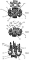
Figures 6A to 6E show the terminal assembly according to a second exemplary embodiment during manufacturing and illustrate successive steps of manufacturing. -
Figure 7 shows a support element of the terminal assembly of the second embodiment. -
Figure 8 shows a cut perspective view of the terminal assembly shown infigure 6E . -
Figure 9 is an enlarged view of a part of the cut perspective view offigure 8 , showing more precisely the heat flow from the terminal to the thermal sensor. - A vehicle driven by an electric motor, also referred as an electric vehicle, comprises electric batteries to supply electrical power to the electric motor. The electric batteries can be electrically charged at a charging station. The vehicle can be connected to the charging station with a charging cable having two charging plugs at both ends. The first charging plug of the charging cable is plugged into a charging connector in the form of a charging socket on the vehicle, also referred as a "charging inlet". The second charging plug of the charging cable is plugged into a charging connector in the form of a charging socket on the charging station, also referred as a "charging outlet". When the electric batteries of the vehicle are being electrically charged, a charging current is transmitted from the charging station to the vehicle via the charging cable.
- In the present disclosure, the terms "charging connector" may refer to a charging inlet on a vehicle, or a charging outlet on a charging station, or a charging plug on a charging cable. The charging connector may be used to charge electric devices other than electric vehicle.
- A charging connector has a terminal assembly. The terminal assembly has a number of N terminals for transmitting a charging current, with N≥1, and a temperature monitoring device. Advantageously, the terminal assembly has also a housing element for holding the N terminals.
- A terminal may also be referred as a "pin" or a "contact element". The function of a terminal is to transmit a charging current. Since the charging currents can be high, the temperature of a terminal may rise and cause an overheating of the components of the charging connector. Therefore, it is necessary to monitor the temperature of the N terminals and to be able to quickly detect an excessive rise in temperature of at least one terminal, in order to reduce or switch off the charging current before any damage to the components.
- The temperature monitoring device performs temperature monitoring in order to detect an excessive rise in temperature of one or more terminals and, if an excessive rise of temperature is detected, the charging current can be reduced or switched off. The temperature monitoring device has a support element and M thermal sensors, with M≥1, for monitoring the temperature of the N terminals. The M thermal sensors are mounted on a first surface of the support element. The support element is for example a printed circuit board.
- In the terminal assembly, the N terminals and the temperature monitoring device are assembled with the housing element.
- The housing element has one or more holes for receiving a thermal interface material.
- A thermal interface material is a material that is usually inserted between two components in order to enhance the thermal coupling between them. The thermal interface material is thermally conductive. The thermal conductivity of the thermal interface material is advantageously equal with or superior to 1 W / m-K. It can be a liquid dispensed material that will cure at room temperature or with the addition of heat. The thermal interface material can be a liquid gap filling material, for example the product referenced as "BERGQUIST® GAP FILLER TGF 4000" manufactured by Henkel company. In addition, the thermal interface material is an electrically insulating material, advantageously a dielectric material.
- Each of the M thermal sensors is immersed in the thermal interface material that fills a space between the first surface of the support element and a corresponding contact surface that is thermally coupled with a corresponding terminal (of the N terminals). In this way, said thermal sensor and the corresponding terminal are thermally coupled by the thermal interface material and the corresponding contact surface.
- Each of the M thermal sensors is immersed in the thermal interface material filling a corresponding container. More precisely, said container receiving the thermal sensor is formed by the surfaces including an inner surface of a hole in the housing element, the first surface of the support element, and the corresponding contact surface that is thermally coupled with the corresponding terminal. In other words, the space filled with the thermal interface material is inside a container made by an inner surface of a hole in the housing element, the first surface of the support element (the one supporting the at least one thermal sensor) and the contact surface.
- As previously indicated, each of the M thermal sensors is immersed in the thermal interface material that fills a space between the first surface of the support element and a corresponding contact surface that is thermally coupled with a corresponding terminal (of the N terminals). In a first exemplary embodiment, said corresponding contact surface is formed by a surface area of the corresponding terminal. For example, this surface area of the corresponding terminal is surrounded by an edge of one opening of a through hole in the housing element. In a second exemplary embodiment, said corresponding contact surface is formed by a lamella metal spring that is in contact with the corresponding terminal.
- The number N of terminals is for example equal to the number M of thermal sensors. In such a case, one thermal sensor monitors one terminal.
- In case of DC (Direct Current) charging, the number N of terminals can be two. In case of AC (Alternating Current) charging, the number N of terminals can be four.
- A method for manufacturing a terminal assembly for a charging connector,, such as the above described terminal assembly, comprises the steps of
- providing a number N of terminals for transmitting a charging current, with N≥1;
- providing a temperature monitoring device comprising a support element and a number M of thermal sensors for monitoring the temperature of the N terminals, with M≥1, said M thermal sensors being mounted on a first surface of said support element; and
- providing a housing element for holding the N terminals,
- Furthermore, the method comprises a step of dispensing a thermal interface material, in liquid state, in the housing element on respective contact surfaces intended to be thermally coupled with the N terminals. When the thermal interface material is still in liquid state, the M thermal sensors are immersed in the thermal interface material by putting the support element, which first surface faces downwards, on a top surface of the liquid. Then, the thermal interface material is cured.
- In a first exemplary embodiment, the N terminals and the housing element are assembled prior to the step of dispensing the thermal interface material. Then, in the step of dispensing, the thermal interface material is dispensed on respective contact surfaces, formed by respective surface areas of the M terminals, through holes in the housing element.
- In a second exemplary embodiment, M lamella metal springs are mounted into holes in the housing element, prior to the step of dispensing the thermal interface material. In the step of dispensing, the thermal interface material covers a surface of each of the M lamella metal springs. Then, after the steps of dispensing the thermal interface material and immersing the M thermal sensors in the thermal interface material, the N terminals and the housing element are assembled. In assembling the N terminals and the housing element, each of the M lamella metal springs is put in contact with a corresponding terminal of the M terminals.
- The at least one terminal, the temperature monitoring device and the housing element are assembled in order to form the terminal assembly. Different methods of assembling can be used.
- The terminal assembly and the method for manufacturing the terminal assembly will now be described in more detail with reference to the figures that represent a first and second exemplary embodiments.
- The same, analogous or corresponding elements represented in the different figures have the same references, unless otherwise stated.
-
Figures 1A and 1B show a first exemplary embodiment of aterminal assembly 1 for a charging connector, for example the charging connector on the vehicle.Figure 1B is analogous tofigure 1A but shows some of the structural elements of theterminal assembly 1 offigure 1A in semitransparency, in order to facilitate the understanding of the structure of theterminal assembly 1. - In the first exemplary embodiment, the
terminal assembly 1 has two terminals 10 (N=2), for transmitting a charging current, ahousing element 11 and atemperature monitoring device 12. Thisterminal assembly 1 of the first exemplary embodiment is suitable for a DC (Direct Current) charging connector. - The
temperature monitoring device 12 has asupport element 120 and two thermal sensors 121 (M=2) for detecting a rise in temperature of the tworespective terminals 10. Thesupport element 120 can be formed by a printed circuit board that has afirst surface 122 on which the twothermal sensors 121 are mounted. The printedcircuit board 120 is made of an electrically insulating material and supports electrical conducting tracks (non represented). - The
housing element 11 holds the twoterminals 10. The two terminals extend along two parallel axis and have for example a circular cross section. The terminals may have any other shape. Each terminal 10 projects from thehousing element 11 by means of afirst end 10A, and is held by thehousing element 11 by means of ashank portion 10B that is next to asecond end 10C, opposite to thefirst end 10A, as shown infigure 4 . Thesecond end 10C is intended to make electrical contact with a conductor element of the charging connector integrating theterminal assembly 1. Thefirst end 10A is intended to make electrical contact with a conductor element of a mating charging connector to which said charging connector is connected. - The
housing element 11 can be made of a plastic material. It can be over-molded on the twoterminals 10. - The
housing element 11 has aninsertion part 110, that can be viewed for example infigure 3A , in which thetemperature monitoring device 12 is inserted. - The
housing element 11 has twoholes 111, that can be viewed infigure 3A . Theseholes 111 are provided through a bottom wall of theinsertion part 110. This bottom wall is over-molded on theshank portions 10B of the twoterminals 10. Therefore, each throughhole 111 has an opening (the lower opening infigure 3A ) which edge is in contact with theshank portion 10B of the correspondingterminal 10 and surrounds asurface area 100 of the terminal 10. Eachhole 111 forms like a window between the terminal 10 (more precisely thesurface area 100 of theshank portion 10B) and the inside of theinsertion part 110 of thehousing element 11. - The
support element 120 has an external shape that fits the inside of theinsertion part 110, as shown infigures 1A, 1B and2 . Thesupport element 120 is inserted in theinsertion part 110 and disposed at the bottom of theinsertion part 110, the first surface of the support element 120 (the one supporting the thermal sensors 121) being oriented towards the bottom of theinsertion part 110. - In the present exemplary embodiment, the
housing element 11 has a plurality of fixingpins 112 protruding on a surface at the bottom of theinsertion part 110. These fixingpins 112 are inserted into corresponding holes provided through thesupport element 120, in order to facilitate assembling thehousing element 111 and thesupport element 120. - A container is formed by the inner surface of each
hole 111 in thehousing element 11, the first surface of the support element 120 (the one supporting the thermal sensors), and a contact surface consisting of thesurface area 100 of the correspondingterminal 10. As shown infigure 4 , the inside of the container is filled with athermal interface material 13 and the correspondingthermal sensor 121 is immersed in thethermal interface material 13. Thethermal sensor 121 is advantageously disposed in front of thesurface area 100 of the terminal. - As a result, each
thermal sensor 121 is thermally coupled with the correspondingterminal 10 by thethermal interface material 13 and thecontact surface 100. As represented infigure 5 , when the terminal 10 generates heat, the heat flow goes directly from thesurface area 100 of the terminal 10 to thethermal sensor 121, through thethermal interface material 13. - The
holes 111 have for example a rectangular shape in a plane that is parallel to the bottom surface of theinsertion part 110. - The
holes 111 can be enlarged next to the bottom surface of theinsertion part 110. The inner surface of each hole is thus configured so that thethermal interface material 13 filling the container comprises a first layer in contact with thecontact surface 100 of the terminal 10 and a second layer in contact with the first surface of thesupport element 120, the second layer being larger than the first layer. In a DC section that is a high voltage section, such a second layer allows to fulfil the requirement of a creepage distance. - A first exemplary embodiment of the method for manufacturing the terminal assembly will now be describe with reference to
figures 3A to 3C . - In a first step (
figure 3A ), the twoterminals 10 and thehousing element 11 are assembled, so as to form a first assembly as represented infigure 3A . For example, thehousing element 11 is overmolded on the twoterminals 10. Thehousing element 11 and the twoterminals 10 are here stably assembled. - In a second step (
figure 3B ), thethermal interface material 13 in liquid state is dispensed in each container formed by the inner surface of eachhole 111 and thecontact surface 100 of the correspondingterminal 10. The arrows oriented downwards represent the operation of dispensing thethermal interface material 13. Each container is filled with thethermal interface material 13 in liquid state up to the point that the top surface of the liquid reaches the surface at the bottom of theinsertion part 110. - In a third step (
figure 3C ), when thethermal interface material 13 is still in liquid state, eachthermal sensor 121 is immersed in thethermal interface material 13. The immersion is performed by putting thesupport element 120, which first surface (the one supporting the thermal sensors 121) faces downwards, on the top surface of the liquid (i.e. the thermal interface material in liquid state). Infigure 3C , the top surface of the thermal interface material in each container is shown in transparency through the support element 120 (in reality, the thermal interface material is under the support element 120). In the third step, thesupport element 120 is inserted into theinsertion part 110 and put on the bottom of saidinsertion part 110, so that the first surface of thesupport element 120 is also put on the top surface of the liquidthermal interface material 13 previously dispensed in the containers. By doing so, thethermal sensors 121, positioned appropriately on thefirst surface 122 of thesupport element 120, are immersed in the liquidthermal interface material 13. Thethermal sensors 121, immersed in thethermal interface material 13, face the respective contact surfaces 100 of theterminals 10. - In a fourth step, the
thermal interface material 13 is cured. For example, it is cured at room temperature or with the addition of heat. - After curing, the
thermal interface material 13 allows to stably assemble thesupport element 120 with the first assembly. - The main function of the
thermal interface material 13 is to transfer the heat generated by theterminals 10 to thethermal sensors 121.Figure 5 illustrates the heat flow (represented by four arrows oriented upwards) between one of theterminals 10 and the associatedthermal sensor 121. The heat generated by the terminal 10 goes through thesurface contact 100 of the terminal 10 and is transferred directly to thethermal sensor 121 through thethermal interface material 13. As thethermal sensor 121 faces thecontact surface 100, the path between the terminal 10 and thethermal sensor 121 through thethermal interface material 13 is very short. With such a configuration, thethermal sensor 121 can detect very quickly a rise in temperature of the terminal 10. -
Figure 6E shows a second exemplary embodiment of aterminal assembly 1 for a charging connector, for example the charging connector on the vehicle. - In this second exemplary embodiment, the
terminal assembly 1 has four terminals 10 (N=4) for transmitting a charging current, ahousing element 11 and atemperature monitoring device 12. This terminal assembly of the second exemplary embodiment is suitable for a AC (Alternating Current) charging connector. - In the second exemplary embodiment, the
temperature monitoring device 12 has asupport element 120 and four thermal sensors 121 (M=4), mounted on afirst surface 122 of thesupport element 120, for detecting a rise in temperature of the fourrespective terminals 10. Thesupport element 120 can be formed by a printed circuit board. The printedcircuit board 120 is made of an electrically insulating material and supports electrical conducting tracks (not represented). - The
housing element 11 holds the fourterminals 10. It has for example an external shape of a flat cylinder, as shown infigures 6A and 6B . Thehousing element 11 can be made of a plastic material. The fourterminals 10 are inserted and retained in fourrespective notches 112 provided in a circle edge of thehousing element 11. - The four
terminals 10 extend along four parallel axis, that are perpendicular to a plane through which thehousing element 11 extends. Theterminals 10 have for example a circular cross section. Each terminal 10 projects from thehousing element 11 by means of afirst end 10A and is held by thehousing element 11 by means of ashank portion 10B that is next to asecond end 10C, opposite to thefirst end 10A. Thesecond end 10C is intended to make electrical contact with a conductor element of the charging connector integrating theterminal assembly 1. Thefirst end 10A is intended to make electrical contact with a conductor element of a mating charging connector to which said charging connector is connected. - The
housing element 11 has aninsertion part 110, in which thetemperature monitoring device 12 is inserted. - The
housing element 11 has fourholes 111, that can be viewed infigures 6A to 6C . Theseholes 111 are provided at the bottom of theinsertion part 110. Eachhole 111 is positioned next to anotch 112 for receiving a terminal 10 and communicates with thenotch 112 through a corresponding opening. - A
lamella metal spring 113 is mounted into eachhole 111. Thelamella metal spring 113 has a body part that lies on a surface at the bottom of thehole 111. This body part is a sheet of metal having a shape that fits the bottom of thehole 111. Thelamella metal spring 113 has two fixing leg parts, perpendicular to the body part, which are inserted into two respective slots provided at the bottom of thehole 111, for fixing thelamella metal spring 113 to thehousing element 11. Thelamella metal spring 113 has also an arm part that extends from the body part towards an end portion, through the opening between thehole 111 and thecorresponding notch 112. This end portion of the spring arm part is in contact with the correspondingterminal 10, as can be viewed infigure 8 . The lamella metal springs 113 are made of a metal material having a good thermal conductivity, for example a copper alloy. - A container is formed by the inner surface of each
hole 111 in thehousing element 11, the first surface of thesupport element 120, and acontact surface 100 of thelamella metal spring 113. As shown infigures 6B and6C , the container defines a space (inside the container) that is filled with athermal interface material 13. The body part of thelamella metal spring 113 is sandwiched between thethermal interface material 13 and the surface at the bottom of thehole 111. - The
contact surface 100 of thelamella metal spring 113 corresponds to the surface area of thelamella metal spring 113 that is in contact with thethermal interface material 13. This contact surface extends over the body part of the lamella metal spring 113 (more precisely, over the surface of the body part that is oriented towards the inside of the hole) and at least partially over the arm part of thelamella metal spring 113. - The
thermal sensor 121 is immersed in thethermal interface material 13, as shown infigures 8 and 9 . It is advantageously disposed in front of the body part of the lamella metal spring. - Each
thermal sensor 121 is thermally coupled with the correspondingterminal 10 by thethermal interface material 13 and thelamella metal spring 113. As represented infigure 9 by arrows, when the terminal 10 generates heat, the heat flow goes from the terminal 10 to thelamella metal spring 113 and then directly from thecontact surface 100 of the arm part and the body part of thelamella metal spring 113 to thethermal sensor 121, through thethermal interface material 13. - Such a configuration allows an efficient and rapid transfer of heat from the
terminals 10 to the associatedthermal sensors 121, which allows a quick detection of an excessive rise in temperature of theterminals 10. - The
terminal assembly 1 has also aprotective cover 123 that is inserted in theinsertion portion 110 of thehousing element 11. - A second exemplary embodiment of the method for manufacturing the
terminal assembly 1 according to the second exemplary embodiment will now be described with reference tofigures 6A to 6E . - In a first step (
figure 6A ), the four lamella metal springs 113 are mounted onto thehousing element 11. Eachlamella metal spring 113 is put on the surface at the bottom of ahole 111 and its two fixing leg parts are inserted in the slots at the bottom of thehole 111. In this position, the arm part of the lamella metal spring extends upwards from the body part of the lamella metal spring lying on the bottom of thehole 111. The angle between the body part and the arm part of the lamella metal spring is slightly superior to 90°. In this way, the arm part of thelamella metal spring 113 extends through the opening between thehole 111 and thecorresponding notch 112 for receiving a terminal 10. - In a second step (
figure 6B ), thethermal interface material 13 in liquid state is dispensed in each container formed by the inner surface of ahole 111 and thelamella metal spring 113 inserted into thishole 111. Thethermal interface material 13 dispensed in the container covers asurface area 100 of thethermal interface material 113, referred as the contact surface of thelamella metal spring 113. This surface area comprises a top surface of the body part of thespring 113 and a partial surface of the arm part of thespring 113. - In a third step (
figure 6C ), when thethermal interface material 13 is still in liquid state, eachthermal sensor 121 is immersed in thethermal interface material 13 by putting thesupport element 120, which first surface (the one supporting the thermal sensors 121) faces downwards, on a top surface of the liquid. More precisely, thesupport element 120 is inserted into theinsertion part 110 and put on the bottom of saidinsertion part 110, so that the first surface of thesupport element 120 is put on the top surface of the liquidthermal interface material 13 previously dispensed in the containers. By doing so, the fourthermal sensors 121, positioned appropriately on the first surface of thesupport element 120, are immersed in the dispensed liquidthermal interface material 13. Thethermal sensors 121, immersed in thethermal interface material 13, face the body parts of the corresponding lamella metal springs 113. - In the third step, a plurality of fixing pins protruding on a surface at the bottom of the
insertion part 110 are inserted into holes provided through thesupport element 120, in order to facilitate assembling thehousing element 111 and thesupport element 120. - In a fourth step, the
thermal interface material 13 is cured. For example, it is cured at room temperature or with the addition of heat. - After curing, the
thermal interface material 13 allows to stably assemble thesupport element 120 with thehousing element 11. - In a fifth step (
figure 6D ), aprotective cover 123 is assembled to the first assembly of thehousing element 11 and thesupport element 120, so as to form a second assembly. - In a sixth step (
figure 6E ), theterminals 10 are assembled with this second assembly, by inserting theterminals 10 in thenotches 112. By doing so, the fourterminals 10 are put into contact with the four lamella metal springs 113. Each terminal 10 pushes the arm part of the correspondinglamella metal spring 113 against thethermal interface material 13, which improves the contact between thelamella metal spring 113 and thethermal interface material 13. - In the first and second exemplary embodiments of the terminal assembly, the number N of terminals is equal to the number M of thermal sensors so that one thermal sensor monitors the temperature of one terminal. However, the number M of thermal sensors might be more than the number N of terminals. In such a case, the temperature of a terminal can be monitored by two or more thermal sensors. Alternatively, the number M of thermal sensors might be less than the number N of terminals. In such a case, the temperature of two or more terminals can be monitored by one thermal sensor.
Claims (15)
- A terminal assembly (1) for a charging connector, comprising- a number N of terminals (10) for transmitting a charging current, with N≥1,- a temperature monitoring device (12), comprising a support element (120) and a number M of thermal sensors (121), with M≥1, for monitoring the temperature of the N terminals (10), said M thermal sensors (121) being mounted on a first surface (122) of said support element (120); characterized in that each of the M thermal sensors (121) is immersed in a thermal interface material (13) that fills a space between the first surface (122) of the support element (120) and a corresponding contact surface (100; 113) that is thermally coupled with a corresponding terminal (10), so that said thermal sensor (121) and the corresponding terminal (10) are thermally coupled by said thermal interface material (13) and said corresponding contact surface (100; 113).
- A terminal assembly according to claim 1, characterized in that the terminal assembly (1) comprises a housing element (11) for holding the N terminals (10) and each of the M thermal sensors is immersed in the thermal interface material (13) filling a container provided by an inner surface of a hole (111) in the housing element (11), the first surface (122) of the support element (120) and said corresponding contact surface (100; 113).
- The terminal assembly according to claim 1 or 2, characterized in that said corresponding contact surface is formed by a surface area (100) of said corresponding terminal (10).
- The terminal assembly according to claim 3, characterized in that each of the M thermal sensors (121) is disposed in front of said surface area (100) of the corresponding terminal (10) forming said corresponding contact surface.
- The terminal assembly according to any of claims 3 and 4, characterized in that the thermal interface material (13) filling said container comprises a first layer in contact with said corresponding contact surface (100) and a second layer in contact with the first surface (122) of the support element (120), and the inner surface of the hole (111) is configured so that the second layer is larger than the first layer.
- The terminal assembly according to claim 1 or 2, characterized in that said corresponding contact surface is part of a lamella metal spring (113) that is in contact with said corresponding terminal (10).
- The terminal assembly according to claim 6 when dependent on claim 2, characterized in that the lamella metal spring (113) comprises a body part that is sandwiched between the thermal interface material (13) and a surface at a bottom of said hole (111) in the housing element (11), and an arm part that extends from the body part towards an end part that is in contact with the corresponding terminal (10).
- The terminal assembly according to claim 7, characterized in that the arm part of the lamella metal spring (113) is in contact with the thermal interface material (13).
- The terminal assembly according to any of claims 1 to 8, characterized in that the thermal conductivity of the thermal interface material (13) is equal with or superior to 1 W / m-K.
- The terminal assembly according to any of claims 2 to 9, characterized in that the number N of terminals is equal to the number M of thermal sensors.
- A charging connector comprising the terminal assembly (1) according to any of claims 1 to 10.
- An electric vehicle or a charging station integrating a charging connector according to claim 11.
- Method for manufacturing a terminal assembly for a charging connector, comprising the steps of- providing a number N of terminals (10) for transmitting a charging current, with N≥1, and- providing a temperature monitoring device (12) comprising a support element (120) and a number M of thermal sensors (121) for monitoring the temperature of the N terminals (10), with M≥1, said M thermal sensors (121) being mounted on a first surface (122) of said support element (120), characterized in that the method comprises the steps of- providing a housing element (11) for holding the N terminals,- dispensing a thermal interface material (13), in liquid state, in the housing element (11) on respective contact surfaces (100; 113) intended to be thermally coupled with the N terminals (10),- when the thermal interface material (13) is still in liquid state, immersing the M thermal sensors (121) in the thermal interface material (13) by putting the support element (120), which first surface faces downwards, on a top surface of the liquid,- and then curing the thermal interface material (13).
- Method according to claim 13, comprising, prior to the step of dispensing the thermal interface material (13), a step of assembling the N terminals (10) and the housing element (11),
wherein said respective contact surfaces are formed by respective surface areas of the M terminals and, in the step of dispensing, the thermal interface material (13) is dispensed on said respective contact surfaces through holes (111) in the housing element (11). - Method according to claim 13, comprising, prior to the step of dispensing the thermal interface material (13), a step of mounting M lamella metal springs (113) into holes (111) in the housing element (11) and, after the steps of dispensing the thermal interface material (13) and immersing the M thermal sensors (121) in said thermal interface material, a step of assembling the N terminals (10) and the housing element (11),
wherein, in the step of dispensing, the thermal interface material (13) covers a surface of each of the M lamella metal springs (113),
and wherein, in the step of assembling the N terminals (10) and the housing element (11), each of the M lamella metal springs (113) is put in contact with a corresponding terminal (10).
Priority Applications (1)
| Application Number | Priority Date | Filing Date | Title |
|---|---|---|---|
| EP20150115.2A EP3846294B1 (en) | 2020-01-02 | 2020-01-02 | Terminal assembly for a charging connector including an improved thermal monitoring |
Applications Claiming Priority (1)
| Application Number | Priority Date | Filing Date | Title |
|---|---|---|---|
| EP20150115.2A EP3846294B1 (en) | 2020-01-02 | 2020-01-02 | Terminal assembly for a charging connector including an improved thermal monitoring |
Publications (2)
| Publication Number | Publication Date |
|---|---|
| EP3846294A1 true EP3846294A1 (en) | 2021-07-07 |
| EP3846294B1 EP3846294B1 (en) | 2025-09-10 |
Family
ID=69104330
Family Applications (1)
| Application Number | Title | Priority Date | Filing Date |
|---|---|---|---|
| EP20150115.2A Active EP3846294B1 (en) | 2020-01-02 | 2020-01-02 | Terminal assembly for a charging connector including an improved thermal monitoring |
Country Status (1)
| Country | Link |
|---|---|
| EP (1) | EP3846294B1 (en) |
Cited By (2)
| Publication number | Priority date | Publication date | Assignee | Title |
|---|---|---|---|---|
| US11641119B2 (en) * | 2018-04-18 | 2023-05-02 | ABB E-mobility B.V. | Detecting a bad contact of a charging cable |
| EP4210176A1 (en) * | 2022-01-10 | 2023-07-12 | HARTING Automotive GmbH | Method for producing an inlet, inlet and multicontact plug |
Citations (6)
| Publication number | Priority date | Publication date | Assignee | Title |
|---|---|---|---|---|
| DE102015004313A1 (en) * | 2015-04-01 | 2016-10-06 | Müller Plastik GmbH | Plug, in particular with a vehicle charging cable of an electric or hybrid vehicle |
| DE102016107401A1 (en) * | 2016-02-26 | 2017-08-31 | Amad Mennekes Holding Gmbh & Co. Kg | Plug-in device with temperature detection |
| EP3286804A1 (en) | 2015-04-23 | 2018-02-28 | Phoenix Contact e-Mobility GmbH | Plug connector part having a temperature-monitoring device |
| WO2018192805A1 (en) * | 2017-04-21 | 2018-10-25 | Phoenix Contact E-Mobility Gmbh | Charging plug for a motor vehicle, and load contact module for a charging plug |
| EP3528349A1 (en) * | 2018-02-15 | 2019-08-21 | Aptiv Technologies Limited | Electrical connector |
| US20190293493A1 (en) * | 2018-03-20 | 2019-09-26 | Te Connectivity Germany Gmbh | Assembly for Detecting Temperature and Contact Assembly Having Such An Assembly |
-
2020
- 2020-01-02 EP EP20150115.2A patent/EP3846294B1/en active Active
Patent Citations (6)
| Publication number | Priority date | Publication date | Assignee | Title |
|---|---|---|---|---|
| DE102015004313A1 (en) * | 2015-04-01 | 2016-10-06 | Müller Plastik GmbH | Plug, in particular with a vehicle charging cable of an electric or hybrid vehicle |
| EP3286804A1 (en) | 2015-04-23 | 2018-02-28 | Phoenix Contact e-Mobility GmbH | Plug connector part having a temperature-monitoring device |
| DE102016107401A1 (en) * | 2016-02-26 | 2017-08-31 | Amad Mennekes Holding Gmbh & Co. Kg | Plug-in device with temperature detection |
| WO2018192805A1 (en) * | 2017-04-21 | 2018-10-25 | Phoenix Contact E-Mobility Gmbh | Charging plug for a motor vehicle, and load contact module for a charging plug |
| EP3528349A1 (en) * | 2018-02-15 | 2019-08-21 | Aptiv Technologies Limited | Electrical connector |
| US20190293493A1 (en) * | 2018-03-20 | 2019-09-26 | Te Connectivity Germany Gmbh | Assembly for Detecting Temperature and Contact Assembly Having Such An Assembly |
Cited By (2)
| Publication number | Priority date | Publication date | Assignee | Title |
|---|---|---|---|---|
| US11641119B2 (en) * | 2018-04-18 | 2023-05-02 | ABB E-mobility B.V. | Detecting a bad contact of a charging cable |
| EP4210176A1 (en) * | 2022-01-10 | 2023-07-12 | HARTING Automotive GmbH | Method for producing an inlet, inlet and multicontact plug |
Also Published As
| Publication number | Publication date |
|---|---|
| EP3846294B1 (en) | 2025-09-10 |
Similar Documents
| Publication | Publication Date | Title |
|---|---|---|
| US11069992B2 (en) | Connector part comprising a circuit board | |
| US10547131B2 (en) | Electrical connection apparatus with improved thermal coupling of a printed circuit board which has a temperature sensor | |
| US10768054B2 (en) | Temperature sensing electrical device | |
| US10985507B2 (en) | Plug connector part having a temperature-monitoring device | |
| US10128624B2 (en) | Power connector system | |
| US12142881B2 (en) | Charging socket with interface | |
| KR20160010478A (en) | Electrical apparatus comprising a temperature sensor housed in a support element | |
| CN113169487A (en) | Connection device with temperature sensor for vehicles | |
| CN105191007A (en) | Right angle header assembly | |
| CN113613940A (en) | Circuit board for electric vehicle charging station | |
| CN115219048A (en) | Temperature measuring device for measuring the temperature of electrical connector terminals | |
| EP3846294B1 (en) | Terminal assembly for a charging connector including an improved thermal monitoring | |
| JP2024156946A (en) | Wiring component with physical quantity sensor and motor control device equipped with same | |
| US20230396027A1 (en) | Temperature detection device for a plug connector part | |
| CN210074317U (en) | Plug-in connector with circuit board | |
| US10753808B2 (en) | Temperature detection device | |
| EP4056410B1 (en) | Electrical connector, charging inlet device and manufacturing method thereof | |
| EP4272994B1 (en) | Electrical connector for vehicle charging inlet | |
| CN106410469A (en) | Connector receptacle, connector assembly, battery busbar assembly, and battery device | |
| CN221201616U (en) | Magnetic attraction male connector | |
| EP4576314A1 (en) | Battery control unit and high voltage power supply system | |
| CN109787042B (en) | electrical connector | |
| JP6894767B2 (en) | Relay terminal module | |
| US20250237553A1 (en) | Temperature Sensor for a High-Voltage Conductor and Method of Manufacturing such a Temperature Sensor | |
| CN115461941A (en) | Device and method for detecting temperature of electrical coupling element |
Legal Events
| Date | Code | Title | Description |
|---|---|---|---|
| PUAI | Public reference made under article 153(3) epc to a published international application that has entered the european phase |
Free format text: ORIGINAL CODE: 0009012 |
|
| STAA | Information on the status of an ep patent application or granted ep patent |
Free format text: STATUS: THE APPLICATION HAS BEEN PUBLISHED |
|
| AK | Designated contracting states |
Kind code of ref document: A1 Designated state(s): AL AT BE BG CH CY CZ DE DK EE ES FI FR GB GR HR HU IE IS IT LI LT LU LV MC MK MT NL NO PL PT RO RS SE SI SK SM TR |
|
| STAA | Information on the status of an ep patent application or granted ep patent |
Free format text: STATUS: REQUEST FOR EXAMINATION WAS MADE |
|
| 17P | Request for examination filed |
Effective date: 20220104 |
|
| RBV | Designated contracting states (corrected) |
Designated state(s): AL AT BE BG CH CY CZ DE DK EE ES FI FR GB GR HR HU IE IS IT LI LT LU LV MC MK MT NL NO PL PT RO RS SE SI SK SM TR |
|
| RAP3 | Party data changed (applicant data changed or rights of an application transferred) |
Owner name: APTIV TECHNOLOGIES LIMITED |
|
| STAA | Information on the status of an ep patent application or granted ep patent |
Free format text: STATUS: EXAMINATION IS IN PROGRESS |
|
| 17Q | First examination report despatched |
Effective date: 20230510 |
|
| RAP1 | Party data changed (applicant data changed or rights of an application transferred) |
Owner name: APTIV TECHNOLOGIES AG |
|
| GRAP | Despatch of communication of intention to grant a patent |
Free format text: ORIGINAL CODE: EPIDOSNIGR1 |
|
| STAA | Information on the status of an ep patent application or granted ep patent |
Free format text: STATUS: GRANT OF PATENT IS INTENDED |
|
| RIC1 | Information provided on ipc code assigned before grant |
Ipc: H01R 24/30 20110101ALN20250425BHEP Ipc: G01K 1/14 20210101ALI20250425BHEP Ipc: B60L 3/04 20060101ALI20250425BHEP Ipc: H01R 13/713 20060101ALI20250425BHEP Ipc: H01R 13/66 20060101AFI20250425BHEP |
|
| INTG | Intention to grant announced |
Effective date: 20250520 |
|
| GRAS | Grant fee paid |
Free format text: ORIGINAL CODE: EPIDOSNIGR3 |
|
| GRAA | (expected) grant |
Free format text: ORIGINAL CODE: 0009210 |
|
| STAA | Information on the status of an ep patent application or granted ep patent |
Free format text: STATUS: THE PATENT HAS BEEN GRANTED |
|
| AK | Designated contracting states |
Kind code of ref document: B1 Designated state(s): AL AT BE BG CH CY CZ DE DK EE ES FI FR GB GR HR HU IE IS IT LI LT LU LV MC MK MT NL NO PL PT RO RS SE SI SK SM TR |
|
| RAP3 | Party data changed (applicant data changed or rights of an application transferred) |
Owner name: APTIV TECHNOLOGIES AG |
|
| REG | Reference to a national code |
Ref country code: GB Ref legal event code: FG4D |
|
| REG | Reference to a national code |
Ref country code: CH Ref legal event code: EP |
|
| REG | Reference to a national code |
Ref country code: DE Ref legal event code: R096 Ref document number: 602020058360 Country of ref document: DE |
|
| REG | Reference to a national code |
Ref country code: IE Ref legal event code: FG4D |
|
| P01 | Opt-out of the competence of the unified patent court (upc) registered |
Free format text: CASE NUMBER: UPC_APP_8771_3846294/2025 Effective date: 20251002 |
|
| PGFP | Annual fee paid to national office [announced via postgrant information from national office to epo] |
Ref country code: GB Payment date: 20251210 Year of fee payment: 7 |
|
| PG25 | Lapsed in a contracting state [announced via postgrant information from national office to epo] |
Ref country code: NO Free format text: LAPSE BECAUSE OF FAILURE TO SUBMIT A TRANSLATION OF THE DESCRIPTION OR TO PAY THE FEE WITHIN THE PRESCRIBED TIME-LIMIT Effective date: 20251210 |
|
| REG | Reference to a national code |
Ref country code: LT Ref legal event code: MG9D |
|
| PG25 | Lapsed in a contracting state [announced via postgrant information from national office to epo] |
Ref country code: FI Free format text: LAPSE BECAUSE OF FAILURE TO SUBMIT A TRANSLATION OF THE DESCRIPTION OR TO PAY THE FEE WITHIN THE PRESCRIBED TIME-LIMIT Effective date: 20250910 |
|
| REG | Reference to a national code |
Ref country code: NL Ref legal event code: MP Effective date: 20250910 |
|
| PG25 | Lapsed in a contracting state [announced via postgrant information from national office to epo] |
Ref country code: HR Free format text: LAPSE BECAUSE OF FAILURE TO SUBMIT A TRANSLATION OF THE DESCRIPTION OR TO PAY THE FEE WITHIN THE PRESCRIBED TIME-LIMIT Effective date: 20250910 |
|
| PGFP | Annual fee paid to national office [announced via postgrant information from national office to epo] |
Ref country code: FR Payment date: 20251202 Year of fee payment: 7 |
|
| PG25 | Lapsed in a contracting state [announced via postgrant information from national office to epo] |
Ref country code: GR Free format text: LAPSE BECAUSE OF FAILURE TO SUBMIT A TRANSLATION OF THE DESCRIPTION OR TO PAY THE FEE WITHIN THE PRESCRIBED TIME-LIMIT Effective date: 20251211 |
|
| PG25 | Lapsed in a contracting state [announced via postgrant information from national office to epo] |
Ref country code: SE Free format text: LAPSE BECAUSE OF FAILURE TO SUBMIT A TRANSLATION OF THE DESCRIPTION OR TO PAY THE FEE WITHIN THE PRESCRIBED TIME-LIMIT Effective date: 20250910 |
|
| PG25 | Lapsed in a contracting state [announced via postgrant information from national office to epo] |
Ref country code: LV Free format text: LAPSE BECAUSE OF FAILURE TO SUBMIT A TRANSLATION OF THE DESCRIPTION OR TO PAY THE FEE WITHIN THE PRESCRIBED TIME-LIMIT Effective date: 20250910 |
|
| PG25 | Lapsed in a contracting state [announced via postgrant information from national office to epo] |
Ref country code: PL Free format text: LAPSE BECAUSE OF FAILURE TO SUBMIT A TRANSLATION OF THE DESCRIPTION OR TO PAY THE FEE WITHIN THE PRESCRIBED TIME-LIMIT Effective date: 20250910 Ref country code: BG Free format text: LAPSE BECAUSE OF FAILURE TO SUBMIT A TRANSLATION OF THE DESCRIPTION OR TO PAY THE FEE WITHIN THE PRESCRIBED TIME-LIMIT Effective date: 20250910 |
|
| PG25 | Lapsed in a contracting state [announced via postgrant information from national office to epo] |
Ref country code: RS Free format text: LAPSE BECAUSE OF FAILURE TO SUBMIT A TRANSLATION OF THE DESCRIPTION OR TO PAY THE FEE WITHIN THE PRESCRIBED TIME-LIMIT Effective date: 20251210 |
|
| PG25 | Lapsed in a contracting state [announced via postgrant information from national office to epo] |
Ref country code: ES Free format text: LAPSE BECAUSE OF FAILURE TO SUBMIT A TRANSLATION OF THE DESCRIPTION OR TO PAY THE FEE WITHIN THE PRESCRIBED TIME-LIMIT Effective date: 20250910 |
|
| REG | Reference to a national code |
Ref country code: AT Ref legal event code: MK05 Ref document number: 1836923 Country of ref document: AT Kind code of ref document: T Effective date: 20250910 |
|
| PG25 | Lapsed in a contracting state [announced via postgrant information from national office to epo] |
Ref country code: NL Free format text: LAPSE BECAUSE OF FAILURE TO SUBMIT A TRANSLATION OF THE DESCRIPTION OR TO PAY THE FEE WITHIN THE PRESCRIBED TIME-LIMIT Effective date: 20250910 |
|
| PG25 | Lapsed in a contracting state [announced via postgrant information from national office to epo] |
Ref country code: SM Free format text: LAPSE BECAUSE OF FAILURE TO SUBMIT A TRANSLATION OF THE DESCRIPTION OR TO PAY THE FEE WITHIN THE PRESCRIBED TIME-LIMIT Effective date: 20250910 |
|
| PGFP | Annual fee paid to national office [announced via postgrant information from national office to epo] |
Ref country code: DE Payment date: 20251217 Year of fee payment: 7 |
|
| PG25 | Lapsed in a contracting state [announced via postgrant information from national office to epo] |
Ref country code: AT Free format text: LAPSE BECAUSE OF FAILURE TO SUBMIT A TRANSLATION OF THE DESCRIPTION OR TO PAY THE FEE WITHIN THE PRESCRIBED TIME-LIMIT Effective date: 20250910 |
|
| PG25 | Lapsed in a contracting state [announced via postgrant information from national office to epo] |
Ref country code: IT Free format text: LAPSE BECAUSE OF FAILURE TO SUBMIT A TRANSLATION OF THE DESCRIPTION OR TO PAY THE FEE WITHIN THE PRESCRIBED TIME-LIMIT Effective date: 20250910 |
|
| PG25 | Lapsed in a contracting state [announced via postgrant information from national office to epo] |
Ref country code: IS Free format text: LAPSE BECAUSE OF FAILURE TO SUBMIT A TRANSLATION OF THE DESCRIPTION OR TO PAY THE FEE WITHIN THE PRESCRIBED TIME-LIMIT Effective date: 20260110 |
|
| PG25 | Lapsed in a contracting state [announced via postgrant information from national office to epo] |
Ref country code: PT Free format text: LAPSE BECAUSE OF FAILURE TO SUBMIT A TRANSLATION OF THE DESCRIPTION OR TO PAY THE FEE WITHIN THE PRESCRIBED TIME-LIMIT Effective date: 20260112 Ref country code: CZ Free format text: LAPSE BECAUSE OF FAILURE TO SUBMIT A TRANSLATION OF THE DESCRIPTION OR TO PAY THE FEE WITHIN THE PRESCRIBED TIME-LIMIT Effective date: 20250910 |
|
| PG25 | Lapsed in a contracting state [announced via postgrant information from national office to epo] |
Ref country code: EE Free format text: LAPSE BECAUSE OF FAILURE TO SUBMIT A TRANSLATION OF THE DESCRIPTION OR TO PAY THE FEE WITHIN THE PRESCRIBED TIME-LIMIT Effective date: 20250910 Ref country code: SK Free format text: LAPSE BECAUSE OF FAILURE TO SUBMIT A TRANSLATION OF THE DESCRIPTION OR TO PAY THE FEE WITHIN THE PRESCRIBED TIME-LIMIT Effective date: 20250910 |