EP3846268A1 - Apparatus for pressing battery cell - Google Patents
Apparatus for pressing battery cell Download PDFInfo
- Publication number
- EP3846268A1 EP3846268A1 EP20866927.5A EP20866927A EP3846268A1 EP 3846268 A1 EP3846268 A1 EP 3846268A1 EP 20866927 A EP20866927 A EP 20866927A EP 3846268 A1 EP3846268 A1 EP 3846268A1
- Authority
- EP
- European Patent Office
- Prior art keywords
- battery cell
- pressing plate
- pressing
- battery
- shape memory
- Prior art date
- Legal status (The legal status is an assumption and is not a legal conclusion. Google has not performed a legal analysis and makes no representation as to the accuracy of the status listed.)
- Pending
Links
Images

Classifications
-
- H—ELECTRICITY
- H01—ELECTRIC ELEMENTS
- H01M—PROCESSES OR MEANS, e.g. BATTERIES, FOR THE DIRECT CONVERSION OF CHEMICAL ENERGY INTO ELECTRICAL ENERGY
- H01M10/00—Secondary cells; Manufacture thereof
- H01M10/04—Construction or manufacture in general
- H01M10/0468—Compression means for stacks of electrodes and separators
-
- H—ELECTRICITY
- H01—ELECTRIC ELEMENTS
- H01M—PROCESSES OR MEANS, e.g. BATTERIES, FOR THE DIRECT CONVERSION OF CHEMICAL ENERGY INTO ELECTRICAL ENERGY
- H01M10/00—Secondary cells; Manufacture thereof
- H01M10/04—Construction or manufacture in general
- H01M10/0481—Compression means other than compression means for stacks of electrodes and separators
-
- B—PERFORMING OPERATIONS; TRANSPORTING
- B30—PRESSES
- B30B—PRESSES IN GENERAL
- B30B1/00—Presses, using a press ram, characterised by the features of the drive therefor, pressure being transmitted directly, or through simple thrust or tension members only, to the press ram or platen
- B30B1/005—Presses, using a press ram, characterised by the features of the drive therefor, pressure being transmitted directly, or through simple thrust or tension members only, to the press ram or platen by thermal expansion or evaporation
-
- H—ELECTRICITY
- H01—ELECTRIC ELEMENTS
- H01M—PROCESSES OR MEANS, e.g. BATTERIES, FOR THE DIRECT CONVERSION OF CHEMICAL ENERGY INTO ELECTRICAL ENERGY
- H01M10/00—Secondary cells; Manufacture thereof
- H01M10/04—Construction or manufacture in general
- H01M10/0463—Cells or batteries with horizontal or inclined electrodes
-
- H—ELECTRICITY
- H01—ELECTRIC ELEMENTS
- H01M—PROCESSES OR MEANS, e.g. BATTERIES, FOR THE DIRECT CONVERSION OF CHEMICAL ENERGY INTO ELECTRICAL ENERGY
- H01M10/00—Secondary cells; Manufacture thereof
- H01M10/05—Accumulators with non-aqueous electrolyte
- H01M10/052—Li-accumulators
-
- H—ELECTRICITY
- H01—ELECTRIC ELEMENTS
- H01M—PROCESSES OR MEANS, e.g. BATTERIES, FOR THE DIRECT CONVERSION OF CHEMICAL ENERGY INTO ELECTRICAL ENERGY
- H01M10/00—Secondary cells; Manufacture thereof
- H01M10/05—Accumulators with non-aqueous electrolyte
- H01M10/058—Construction or manufacture
-
- H—ELECTRICITY
- H01—ELECTRIC ELEMENTS
- H01M—PROCESSES OR MEANS, e.g. BATTERIES, FOR THE DIRECT CONVERSION OF CHEMICAL ENERGY INTO ELECTRICAL ENERGY
- H01M10/00—Secondary cells; Manufacture thereof
- H01M10/05—Accumulators with non-aqueous electrolyte
- H01M10/058—Construction or manufacture
- H01M10/0585—Construction or manufacture of accumulators having only flat construction elements, i.e. flat positive electrodes, flat negative electrodes and flat separators
-
- H—ELECTRICITY
- H01—ELECTRIC ELEMENTS
- H01M—PROCESSES OR MEANS, e.g. BATTERIES, FOR THE DIRECT CONVERSION OF CHEMICAL ENERGY INTO ELECTRICAL ENERGY
- H01M2200/00—Safety devices for primary or secondary batteries
- H01M2200/10—Temperature sensitive devices
-
- Y—GENERAL TAGGING OF NEW TECHNOLOGICAL DEVELOPMENTS; GENERAL TAGGING OF CROSS-SECTIONAL TECHNOLOGIES SPANNING OVER SEVERAL SECTIONS OF THE IPC; TECHNICAL SUBJECTS COVERED BY FORMER USPC CROSS-REFERENCE ART COLLECTIONS [XRACs] AND DIGESTS
- Y02—TECHNOLOGIES OR APPLICATIONS FOR MITIGATION OR ADAPTATION AGAINST CLIMATE CHANGE
- Y02E—REDUCTION OF GREENHOUSE GAS [GHG] EMISSIONS, RELATED TO ENERGY GENERATION, TRANSMISSION OR DISTRIBUTION
- Y02E60/00—Enabling technologies; Technologies with a potential or indirect contribution to GHG emissions mitigation
- Y02E60/10—Energy storage using batteries
-
- Y—GENERAL TAGGING OF NEW TECHNOLOGICAL DEVELOPMENTS; GENERAL TAGGING OF CROSS-SECTIONAL TECHNOLOGIES SPANNING OVER SEVERAL SECTIONS OF THE IPC; TECHNICAL SUBJECTS COVERED BY FORMER USPC CROSS-REFERENCE ART COLLECTIONS [XRACs] AND DIGESTS
- Y02—TECHNOLOGIES OR APPLICATIONS FOR MITIGATION OR ADAPTATION AGAINST CLIMATE CHANGE
- Y02P—CLIMATE CHANGE MITIGATION TECHNOLOGIES IN THE PRODUCTION OR PROCESSING OF GOODS
- Y02P70/00—Climate change mitigation technologies in the production process for final industrial or consumer products
- Y02P70/50—Manufacturing or production processes characterised by the final manufactured product
Definitions
- the present disclosure relates to an apparatus for pressing a battery cell, and more particularly to an apparatus for pressing a battery cell using a shape memory material.
- Secondary batteries which are easily applied to various product groups and has electrical characteristics such as high energy density, are universally applied not only for a portable device but also for an electric vehicle or a hybrid electric vehicle, an energy storage system or the like, which is driven by an electric driving source.
- Such secondary battery is attracting attention as a new environment-friendly energy source for improving energy efficiency since it gives a primary advantage of remarkably reducing the use of fossil fuels and also does not generate by-products from the use of energy at all.
- a nickel-cadmium battery or a hydrogen ion battery has been used as the secondary battery.
- a lithium secondary battery is recently widely used because charging and discharging is free due to rare memory effect in comparison with a nickel-based secondary battery, a self-discharge rate is very low, and an energy density is high.
- the lithium secondary battery mainly uses a lithium oxide and a carbonaceous material as a positive electrode active material and a negative electrode active material, respectively.
- the lithium secondary battery includes an electrode assembly in which a positive electrode plate and a negative electrode plate, respectively coated with the positive electrode active material and the negative electrode active material, are arranged with a separator therebetween, and an exterior material, that is a battery case, which seals and receives the electrode assembly together with an electrolyte solution.
- the lithium secondary battery includes a positive electrode, a negative electrode, and a separator and an electrolyte interposed therebetween.
- the lithium secondary battery is classified into a lithium ion battery and a polymer lithium ion battery.
- an electrode of the lithium secondary battery is prepared by applying the positive or negative electrode active material to a current collector made of aluminum or copper sheet, mesh, film, foil, or the like and then drying the same.
- An apparatus for pressing a battery cell includes a first pressing plate and a second pressing plate, which form a space therebetween such that a battery cell is disposed, and press the battery cell, wherein at least one of the first pressing plate and the second pressing plate is formed of a shape memory material.
- the pressing member allows its shape to store in accordance with the battery cell at a temperature at which the battery cell is driven, and then, deformation of the pressing member due to a volume expansion of the battery cell acts as a force for returning the shape of the pressing member to an original shape of the pressing member after the driving of the battery cell, thereby pressing the battery cell.
- An interval between the first pressing plate and the second pressing plate may be increased by a volume expansion of the battery cell.
- An upper surface of the first pressing plate and a lower surface of the second pressing plate are pressed by the expansion of the battery cell in a thickness direction of the battery cell so that the shapes of the first pressing plate and the second pressing plate may be changed.
- the interval between the first pressing plate and the second pressing plate may be reduced.
- the shape memory material may include a shape memory polymer.
- the battery cell may be configured so that an electrode assembly of a structure having a positive electrode, a negative electrode, and a separator interposed between the positive electrode and the negative electrode is sealed together with an electrolyte in the interior of a battery case.
- the first pressing plate may make contact with a lower surface of the battery case
- the second pressing plate may make contact with an upper surface of the battery case
- a side surface of the battery case, which is located between the first pressing plate and the second pressing plate, may be exposed to the outside.
- the first pressing plate and the second pressing plate may be coupled to each other by coupling fins.
- the coupling fins may be formed of a plurality of fins and may be formed of springs.
- the coupling fins may be formed of a plurality of fins and may be formed of the shape memory material.
- the coupling fins may be formed of a shape memory polymer.
- An interval between the first pressing plate and the second pressing plate may be identical to or larger than the thickness of the battery cell.
- the battery cell may be a lithium metal cell.
- the first pressing plate and the second pressing plate have areas that may be larger than the area of the battery cell.
- the apparatus for pressing a battery cell which uses the shape memory material in the lithium metal cell, the restoring force due to the volume change of the battery cell can be generated, thereby realizing a constant pressure jig effect. Accordingly, a high force, which is necessary for the lithium metal cell, may be provided by an excellent shape restoring force with a light weight.
- planar when referred to as “planar”, it means when a target portion is viewed from the top, and when referred to as “cross-sectional”, it means when a target portion is viewed from the side of a cross section cut vertically.
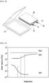
- FIG. 1 is a side view illustrating a state in which a secondary battery cell is disposed in an apparatus for pressing a battery cell according to an embodiment of the present disclosure.
- FIG. 2 is a front view of the battery cell pressing device of FIG. 1 .
- FIG. 3 is a perspective view illustrating a structure of a lithium secondary battery.
- FIG. 4 is a graph depicting elastic moduli according to temperature.
- the apparatus for pressing a battery cell 500 includes a pair of pressing plates 100a and 100b coupled to each other by a plurality of coupling fins 120, and a battery cell 1 located between the pair of pressing plates 100a and 100b.
- the coupling fin 120 according to the present embodiment may be formed of springs.
- a plurality of coupling fins 120 may be disposed at four corners on planes of pressing plates 100a and 100b.
- the first pressing plate 100a and the second pressing plate 100b may be disposed to be spaced apart from each other due to a coupling form of the coupling fins 120.
- a space, in which the battery cell 1 may be disposed is formed between the first pressing plate 100a and the second pressing plate 100b, which are spaced apart from each other.
- the inner width of the space, in which the battery cell 1 is disposed, that is an interval between the pressing plates 100a and 100b, may be identical to or slightly larger than the thickness of the battery cell 1.
- Electrode leads 31 and 32 are protruded in one direction of the battery cell 1 according to the present embodiment, and the electrode leads 31 and 32 may be protruded between the two coupling fins 120 located on sides of the pressing plates 100a and 100b.
- At least one of the pressing plates 100a and 100b according to the present embodiment is a pressing member formed of a shape memory material.
- a shape memory material is a material having a shape memory effect that stores the shape stored at a specific temperature, transforms it into a completely different shape as a force is applied, and returns to its original shape when being heated.
- the pressing member formed of the shape memory material stores a shape in accordance with the battery cell 1 at a temperature at which the battery cell 1 is driven, and then, deformation of the pressing member due to a volume expansion of the battery cell acts as a force for returning the shape of the pressing member to the original shape of the pressing member after the driving of the battery cell 1 such that the battery cell 1 is pressed by the pressing member.
- the battery cell 1 when the battery cell 1 is swelled, the battery cell 1 pushes out the pressing member formed of the shape memory material, and the battery cell 1 is pressed by the force that tends to always return the shape of the pressing member to the original shape of the pressing member due to the characteristics of a memory material.
- the first and second pressing plates 100a and 100b expands in a thickness direction of the battery cell 1, an upper surface of the first pressing plate 100a and a lower surface of the second pressing plate 100b are pressed, and accordingly, the shapes of the first and second pressing plates 100a and 100b are changed. That is, the interval between the first pressing plate 100a and the second pressing plate 100b is increased by the volume expansion of the battery cell 1. Thereafter, if heat is applied to the apparatus for pressing a battery cell 500, a restoring force that tends to return the first and second pressing plates 100a and 100b to the original shape thereof is generated so that the restoring force can be applied to the battery cell 1 to restrain the volume expansion of the battery cell 1. If the expanded volume of the battery cell 1 may be decreased by a discharge of the battery cell 1, the interval between the first pressing plate 100a and the second pressing plate 100b may be reduced.
- a dendrite phenomenon of causing an explosion or shortening lifetime in a lithium metal battery may occur.
- the dendrite phenomenon refers to production of crystal of a branch shape, which is formed on a surface of a lithium metal. That is, the apparatus for pressing a battery cell according to the present embodiment may be applied to implement the required pressurization when the lithium dendrite phenomenon occurs in the lithium metal battery.
- the battery cell 1, to which the apparatus for pressing a battery cell according to the present embodiment is applied corresponds to a lithium metal cell
- the lithium metal cell has a large volume expansion during charging and discharging.
- lifetime performance during cycles of charging and discharging is superior to that when it is not pressed. Therefore, in the case of a lithium metal cell, a pressurizing device is absolutely necessary.
- a high pressure of a maximum of 4 MPa is required, and a thick and heavy apparatus for pressing a battery cell made of a metal material having a high strength may be used, but because the pressing apparatus is bulky and heavy, it may be disadvantageous in terms of large energy density, which is the greatest benefit when the lithium metal is applied to a negative electrode. Accordingly, when the pressing member formed of the shape memory material is used according to the present embodiment, a pressing apparatus, which is small and light while applying a high force, may be implemented. When a spring jig that applies a specific pressure is used, the lifetime performance of the pressing apparatus may be improved as compared with when a static jig having fixed thickness is used in the apparatus for pressing a battery cell is used. According to the present embodiment, a constant pressure jig, such as a spring jig, may be implemented as the pressing member formed of the shape memory material is used.
- the shape memory effect is realized by the pressing member of the shape memory material according to the present embodiment, and the restoring force due to a volume change of the battery cell 1 is generated to operate as the constant pressure jig effect.
- the battery cell according to the present embodiment is configured so that an electrode assembly 20 formed of a positive electrode, a negative electrode, and a separator interposed therebetween is embedded in the interior of the battery case 10. Electrode tabs 21 and 22 protruding from the positive electrode and the negative electrode of the electrode assembly 20 may be installed to be electrically connected to the electrode leads 31 and 32 of the positive electrode and the negative electrode, respectively, to be exposed to the outside.
- the first pressing plate 100a may make contact with a lower surface of the battery case 10
- the second pressing plate 100b may make contact with the an upper surface of the battery case 10
- side surfaces of the battery case 10 which is located between the first pressing plate 100a and the second pressing plate 100b, may be exposed to the outside.
- the side surfaces of the battery case 10 has four surfaces, and it is preferable that all of the four surfaces are exposed to the outside. The reason for this structure will be explained while a case in which the battery case itself surrounding the battery cell is formed of a shape memory alloy is taken as a comparative example.
- the volume change of the lithium metal cell, to which the embodiment of the present disclosure is applied, is very large when being charged and discharged once unlike a cell included in a lithium ions battery, and the thickness of the battery cell continuously increases as the cycle is repeated because lithium dendrite is continuously formed.
- the thickness difference is very large so that a pressure may not be applied in a SOC0 state if the apparatus for pressing is made to have the thickness corresponding to SOC100 of the battery cell, .
- EOL end of life
- the shape memory material according to the present embodiment may be a shape memory polymer.
- the shape memory polymer may be highly elastically deformed as compared with the shape memory alloy, and has advantages of low costs, a low density, an excellent shape restoring force, and a high tensile strength.
- the shape memory polymer is used in the pressing plates included in the apparatus for pressing, a high force of approximately 400% or more of a restoring force, which is necessary when the pressing plates are applied to a lithium metal cell, that is, a restoring stress, can be provided.
- FIG. 4 is a graph relating to the elastic moduli according to temperature
- steel refers to a steel metal
- SMA refers to a shape memory alloy
- SMP refers to a shape memory polymer.
- the value of elastic modulus of SMP is lower than the value of elastic modulus of SMA in a specified temperature section. This indicates that SMP can be prolonged better than SMA.
- an interval between the pressing plates 100a and 100b of the apparatus for pressing a battery cell 100 should increase so that a pressure applied to the battery cell 1 is uniform.
- SMP is prolonged better as compared with SMA, the pressure applied to the battery cell 1 is lower in SMP than in SMA. Accordingly, SMP is more suitable for the constant pressure jig type of the lithium metal battery, than SMA.
- the origin of the graph in FIG. 4 are as follows: Tobushi, Hisaaki, Shunichi Hayashi, and Yoshiki Sugimoto. "Two-way bending properties of shape memory composite with SMA and SMP.” Materials 2.3 (2009): 1180-1192 .
- the battery cell 1 While the battery cell 1 is disposed in the interior of the apparatus for pressing a battery cell, and the first and second pressing plates 100a and 100b are coupled to each other by the coupling fins 120, the battery cell expands and the thickness thereof increases if an activation and aging process is performed on the battery cell 1.
- an activation and aging process before release of a product has been mentioned, but it is not limited to a process step, and the apparatus for pressing a battery cell according to the embodiment of the present disclosure may be applied to a battery cell driving step.
- the pair of the pressing plates 100a and 100b are formed of the shape memory material and are coupled to each other by the coupling fins 120, and thus they are light-weighted and are easy to handle.
- the pressing plates 100a and 100b are formed of the shape memory material and thus they can be light-weighted and are light in weight and may be suitable for use for a battery, in which energy density per weight is important like drones.
- the coupling fins 120 are formed of the springs, but the coupling fins 120 may be formed of the shape memory material as a modified embodiment.
- the length of the coupling fins 120 may be also increase.
- the coupling fins 120 themselves are formed of the shape memory material, the restoring force is generated, and thus the volume expansion of the battery cell 1 can be further restrained due to the restoring force.
- the coupling fins 120 may be also formed of the shape memory polymer.
- the coupling fins 120 may be also formed of the shape memory polymer.
Landscapes
- Engineering & Computer Science (AREA)
- Manufacturing & Machinery (AREA)
- Chemical & Material Sciences (AREA)
- Chemical Kinetics & Catalysis (AREA)
- Electrochemistry (AREA)
- General Chemical & Material Sciences (AREA)
- Physics & Mathematics (AREA)
- Thermal Sciences (AREA)
- Mechanical Engineering (AREA)
- Secondary Cells (AREA)
- Battery Electrode And Active Subsutance (AREA)
Abstract
Description
- This application claims the benefit of
Korean Patent Application No. 10-2019-0140360 filed on November 5, 2019 - The present disclosure relates to an apparatus for pressing a battery cell, and more particularly to an apparatus for pressing a battery cell using a shape memory material.
- Secondary batteries, which are easily applied to various product groups and has electrical characteristics such as high energy density, are universally applied not only for a portable device but also for an electric vehicle or a hybrid electric vehicle, an energy storage system or the like, which is driven by an electric driving source. Such secondary battery is attracting attention as a new environment-friendly energy source for improving energy efficiency since it gives a primary advantage of remarkably reducing the use of fossil fuels and also does not generate by-products from the use of energy at all.
- Conventionally, a nickel-cadmium battery or a hydrogen ion battery has been used as the secondary battery. However, a lithium secondary battery is recently widely used because charging and discharging is free due to rare memory effect in comparison with a nickel-based secondary battery, a self-discharge rate is very low, and an energy density is high.
- The lithium secondary battery mainly uses a lithium oxide and a carbonaceous material as a positive electrode active material and a negative electrode active material, respectively. The lithium secondary battery includes an electrode assembly in which a positive electrode plate and a negative electrode plate, respectively coated with the positive electrode active material and the negative electrode active material, are arranged with a separator therebetween, and an exterior material, that is a battery case, which seals and receives the electrode assembly together with an electrolyte solution.
- The lithium secondary battery includes a positive electrode, a negative electrode, and a separator and an electrolyte interposed therebetween. Depending on which material is used for the positive electrode active material and the negative electrode active material, the lithium secondary battery is classified into a lithium ion battery and a polymer lithium ion battery. Generally, an electrode of the lithium secondary battery is prepared by applying the positive or negative electrode active material to a current collector made of aluminum or copper sheet, mesh, film, foil, or the like and then drying the same.
- Meanwhile, it is necessary to attach a positive electrode plate, a negative electrode plate, and a separator to each other uniformly as a whole such that the reaction can occur uniformly in all parts of secondary battery. Therefore, there is a need to develop of an apparatus for pressing a secondary battery in a balanced manner.
- It is an object of the present disclosure to provide an apparatus for pressing a battery cell, which realizes constant pressure.
- However, the problem to be solved by embodiments of the present disclosure is not limited to the above-described problems, and can be variously expanded within the scope of the technical idea included in the present disclosure.
- An apparatus for pressing a battery cell according to an embodiment of the present disclosure includes a first pressing plate and a second pressing plate, which form a space therebetween such that a battery cell is disposed, and press the battery cell, wherein at least one of the first pressing plate and the second pressing plate is formed of a shape memory material.
- The pressing member allows its shape to store in accordance with the battery cell at a temperature at which the battery cell is driven, and then, deformation of the pressing member due to a volume expansion of the battery cell acts as a force for returning the shape of the pressing member to an original shape of the pressing member after the driving of the battery cell, thereby pressing the battery cell.
- An interval between the first pressing plate and the second pressing plate may be increased by a volume expansion of the battery cell.
- An upper surface of the first pressing plate and a lower surface of the second pressing plate are pressed by the expansion of the battery cell in a thickness direction of the battery cell so that the shapes of the first pressing plate and the second pressing plate may be changed.
- When the volume of the battery cell is reduced, the interval between the first pressing plate and the second pressing plate may be reduced.
- The shape memory material may include a shape memory polymer.
- The battery cell may be configured so that an electrode assembly of a structure having a positive electrode, a negative electrode, and a separator interposed between the positive electrode and the negative electrode is sealed together with an electrolyte in the interior of a battery case.
- The first pressing plate may make contact with a lower surface of the battery case, the second pressing plate may make contact with an upper surface of the battery case, and a side surface of the battery case, which is located between the first pressing plate and the second pressing plate, may be exposed to the outside.
- The first pressing plate and the second pressing plate may be coupled to each other by coupling fins.
- The coupling fins may be formed of a plurality of fins and may be formed of springs.
- The coupling fins may be formed of a plurality of fins and may be formed of the shape memory material.
- The coupling fins may be formed of a shape memory polymer.
- An interval between the first pressing plate and the second pressing plate may be identical to or larger than the thickness of the battery cell.
- The battery cell may be a lithium metal cell.
- The first pressing plate and the second pressing plate have areas that may be larger than the area of the battery cell.
- According to the embodiments, by using the apparatus for pressing a battery cell , which uses the shape memory material in the lithium metal cell, the restoring force due to the volume change of the battery cell can be generated, thereby realizing a constant pressure jig effect. Accordingly, a high force, which is necessary for the lithium metal cell, may be provided by an excellent shape restoring force with a light weight.
-
-
FIG. 1 is a side view illustrating a state in which a secondary battery cell is disposed in an apparatus for pressing a battery cell according to an embodiment of the present disclosure; -
FIG. 2 is a front view of the apparatus for pressing a battery cell ofFIG. 1 ; -
FIG. 3 is a perspective view illustrating a structure of a lithium secondary battery; and -
FIG. 4 is a graph depicting elastic moduli according to temperature. - Hereinafter, various embodiments of the present disclosure will be described in detail with reference to the accompanying drawings so that those skilled in the art can easily implement them. The present disclosure may be modified in various different ways, and is not limited to the embodiments set forth herein.
- Parts that are irrelevant to the description will be omitted to clearly describe the present disclosure, and like reference numerals designate like elements throughout the specification.
- Further, the size and thickness of each element shown in the figures are arbitrarily illustrated for convenience of description, and the present disclosure is not necessarily limited to those illustrated in the drawings. In the figures, the thickness of layers, regions, etc. are exaggerated for clarity. In the figures, for convenience of description, the thicknesses of some layers and regions are shown to be exaggerated.
- In addition, it will be understood that when an element such as a layer, film, region, or plate is referred to as being "on" or "above" another element, it can be directly on the other element or intervening elements may also be present. In contrast, when an element is referred to as being "directly on" another element, it means that other intervening elements are not present. Further, the word "on" or "above" means disposed on or below a reference portion, and does not necessarily mean being disposed on the upper end of the reference portion toward the opposite direction of gravity.
- Further, throughout the specification, when a part is referred to as "including" or "comprising" a certain component, it means that it can further include other components, without excluding the other components, unless otherwise stated.
- Further, throughout the specification, when referred to as "planar", it means when a target portion is viewed from the top, and when referred to as "cross-sectional", it means when a target portion is viewed from the side of a cross section cut vertically.
-
FIG. 1 is a side view illustrating a state in which a secondary battery cell is disposed in an apparatus for pressing a battery cell according to an embodiment of the present disclosure.FIG. 2 is a front view of the battery cell pressing device ofFIG. 1 .FIG. 3 is a perspective view illustrating a structure of a lithium secondary battery.FIG. 4 is a graph depicting elastic moduli according to temperature. - Referring to
FIGS. 1 and 2 , the apparatus for pressing abattery cell 500 according to the present embodiment includes a pair ofpressing plates coupling fins 120, and abattery cell 1 located between the pair ofpressing plates coupling fin 120 according to the present embodiment may be formed of springs. - A plurality of
coupling fins 120 may be disposed at four corners on planes ofpressing plates pressing plate 100a and the second pressingplate 100b may be disposed to be spaced apart from each other due to a coupling form of the coupling fins 120. A space, in which thebattery cell 1 may be disposed, is formed between the firstpressing plate 100a and the secondpressing plate 100b, which are spaced apart from each other. The inner width of the space, in which thebattery cell 1 is disposed, that is an interval between thepressing plates battery cell 1. - Electrode leads 31 and 32 are protruded in one direction of the
battery cell 1 according to the present embodiment, and the electrode leads 31 and 32 may be protruded between the twocoupling fins 120 located on sides of thepressing plates - At least one of the
pressing plates - The pressing member formed of the shape memory material according to the present embodiment stores a shape in accordance with the
battery cell 1 at a temperature at which thebattery cell 1 is driven, and then, deformation of the pressing member due to a volume expansion of the battery cell acts as a force for returning the shape of the pressing member to the original shape of the pressing member after the driving of thebattery cell 1 such that thebattery cell 1 is pressed by the pressing member. In other words, when thebattery cell 1 is swelled, thebattery cell 1 pushes out the pressing member formed of the shape memory material, and thebattery cell 1 is pressed by the force that tends to always return the shape of the pressing member to the original shape of the pressing member due to the characteristics of a memory material. In detail, if thebattery cell 1 illustrated inFIGS. 1 and 2 expands in a thickness direction of thebattery cell 1, an upper surface of the firstpressing plate 100a and a lower surface of the secondpressing plate 100b are pressed, and accordingly, the shapes of the first and secondpressing plates pressing plate 100a and the secondpressing plate 100b is increased by the volume expansion of thebattery cell 1. Thereafter, if heat is applied to the apparatus for pressing abattery cell 500, a restoring force that tends to return the first and secondpressing plates battery cell 1 to restrain the volume expansion of thebattery cell 1. If the expanded volume of thebattery cell 1 may be decreased by a discharge of thebattery cell 1, the interval between the firstpressing plate 100a and the secondpressing plate 100b may be reduced. - In particular, a dendrite phenomenon of causing an explosion or shortening lifetime in a lithium metal battery may occur. The dendrite phenomenon refers to production of crystal of a branch shape, which is formed on a surface of a lithium metal. That is, the apparatus for pressing a battery cell according to the present embodiment may be applied to implement the required pressurization when the lithium dendrite phenomenon occurs in the lithium metal battery.
- The
battery cell 1, to which the apparatus for pressing a battery cell according to the present embodiment is applied, corresponds to a lithium metal cell, the lithium metal cell has a large volume expansion during charging and discharging. When the lithium metal cell is pressed, lifetime performance during cycles of charging and discharging is superior to that when it is not pressed. Therefore, in the case of a lithium metal cell, a pressurizing device is absolutely necessary. - When the lithium metal cell is driven, a high pressure of a maximum of 4 MPa is required, and a thick and heavy apparatus for pressing a battery cell made of a metal material having a high strength may be used, but because the pressing apparatus is bulky and heavy, it may be disadvantageous in terms of large energy density, which is the greatest benefit when the lithium metal is applied to a negative electrode. Accordingly, when the pressing member formed of the shape memory material is used according to the present embodiment, a pressing apparatus, which is small and light while applying a high force, may be implemented. When a spring jig that applies a specific pressure is used, the lifetime performance of the pressing apparatus may be improved as compared with when a static jig having fixed thickness is used in the apparatus for pressing a battery cell is used. According to the present embodiment, a constant pressure jig, such as a spring jig, may be implemented as the pressing member formed of the shape memory material is used.
- The shape memory effect is realized by the pressing member of the shape memory material according to the present embodiment, and the restoring force due to a volume change of the
battery cell 1 is generated to operate as the constant pressure jig effect. - As illustrated in
FIG. 3 , the battery cell according to the present embodiment is configured so that anelectrode assembly 20 formed of a positive electrode, a negative electrode, and a separator interposed therebetween is embedded in the interior of thebattery case 10.Electrode tabs electrode assembly 20 may be installed to be electrically connected to the electrode leads 31 and 32 of the positive electrode and the negative electrode, respectively, to be exposed to the outside. - According to the present embodiment, the first
pressing plate 100a may make contact with a lower surface of thebattery case 10, the secondpressing plate 100b may make contact with the an upper surface of thebattery case 10, and side surfaces of thebattery case 10, which is located between the firstpressing plate 100a and the secondpressing plate 100b, may be exposed to the outside. Here, the side surfaces of thebattery case 10 has four surfaces, and it is preferable that all of the four surfaces are exposed to the outside. The reason for this structure will be explained while a case in which the battery case itself surrounding the battery cell is formed of a shape memory alloy is taken as a comparative example. - The volume change of the lithium metal cell, to which the embodiment of the present disclosure is applied, is very large when being charged and discharged once unlike a cell included in a lithium ions battery, and the thickness of the battery cell continuously increases as the cycle is repeated because lithium dendrite is continuously formed. When the plates for pressing fixes even the side surfaces of the
battery case 10 in SOC0 state, the thickness difference is very large so that a pressure may not be applied in a SOC0 state if the apparatus for pressing is made to have the thickness corresponding to SOC100 of the battery cell, . Further, when the end of life (EOL) is reached through repeated charging and discharging, the thickness of the battery cells may significantly increase as compared with the initial SOC100, thereby resulting in a larger pressure than the initial SOC100. Accordingly, in the comparative example in which the shape memory alloy is used as the battery case itself, all of the side surfaces thereof are fixed so that it is difficult to apply a specific pressure to the battery cell. In addition, when the battery cell is pressed by using the battery case corresponding to the comparative example, it is difficult to uniformly transfer a force to the area of the electrode. This is because, in the case of a battery case such as a can type, a surface of the battery case, which expands during a volume expansion of a battery cell is curved and thus it is difficult to uniformly press the electrode. - The shape memory material according to the present embodiment may be a shape memory polymer. The shape memory polymer may be highly elastically deformed as compared with the shape memory alloy, and has advantages of low costs, a low density, an excellent shape restoring force, and a high tensile strength.
- According to the present embodiment, because the shape memory polymer is used in the pressing plates included in the apparatus for pressing, a high force of approximately 400% or more of a restoring force, which is necessary when the pressing plates are applied to a lithium metal cell, that is, a restoring stress, can be provided.
- In addition, referring to
FIG. 4 that is a graph relating to the elastic moduli according to temperature, steel refers to a steel metal, SMA refers to a shape memory alloy, and SMP refers to a shape memory polymer. The value of elastic modulus of SMP is lower than the value of elastic modulus of SMA in a specified temperature section. This indicates that SMP can be prolonged better than SMA. As thebattery cell 1 illustrated inFIG. 1 and 2 expands and the thickness of thebattery cell 1 increases, an interval between thepressing plates battery cell 1 is uniform. Here, because SMP is prolonged better as compared with SMA, the pressure applied to thebattery cell 1 is lower in SMP than in SMA. Accordingly, SMP is more suitable for the constant pressure jig type of the lithium metal battery, than SMA. The origin of the graph inFIG. 4 are as follows: Tobushi, Hisaaki, Shunichi Hayashi, and Yoshiki Sugimoto. "Two-way bending properties of shape memory composite with SMA and SMP." Materials 2.3 (2009): 1180-1192. - While the
battery cell 1 is disposed in the interior of the apparatus for pressing a battery cell, and the first and secondpressing plates coupling fins 120, the battery cell expands and the thickness thereof increases if an activation and aging process is performed on thebattery cell 1. Herein, an activation and aging process before release of a product has been mentioned, but it is not limited to a process step, and the apparatus for pressing a battery cell according to the embodiment of the present disclosure may be applied to a battery cell driving step. - The pair of the
pressing plates coupling fins 120, and thus they are light-weighted and are easy to handle. In the above-configured apparatus for pressing a battery cell according to an embodiment of the present disclosure, thepressing plates - In the above-mentioned embodiment, it has been explained that the
coupling fins 120 are formed of the springs, but thecoupling fins 120 may be formed of the shape memory material as a modified embodiment. In this connection, if the interval between the firstpressing plate 100a and the secondpressing plate 100b are increased by the volume expansion of thebattery cell 1, the length of thecoupling fins 120 may be also increase. Because thecoupling fins 120 themselves are formed of the shape memory material, the restoring force is generated, and thus the volume expansion of thebattery cell 1 can be further restrained due to the restoring force. Thecoupling fins 120 may be also formed of the shape memory polymer. Thecoupling fins 120 may be also formed of the shape memory polymer. - Although the preferred embodiments of the present disclosure have been described in detail above, the scope of the present disclosure is not limited thereto, and various modifications and improvements of those skilled in the art using the basic concepts of the present disclosure defined in the following claims also belong to the scope of rights.
-
- 1: battery cell
- 10: battery case
- 20: electrode assembly
- 100a, 100b: pressing plate
Claims (15)
- An apparatus for pressing a battery cell, the apparatus comprising:a first pressing plate and a second pressing plate, which form a space therebetween, such that a battery cell is disposed, and press the battery cell,wherein at least one of the first pressing plate and the second pressing plate is formed of a shape memory material.
- The apparatus of claim 1, wherein the pressing member allows its shape to store in accordance with the battery cell at a temperature at which the battery cell is driven, and then, deformation of the pressing member due to a volume expansion of the battery cell acts as a force for returning the shape of the pressing member to an original shape of the pressing member after the battery cell is driven, thereby pressing the battery cell.
- The apparatus of claim 2, wherein an interval between the first pressing plate and the second pressing plate is increased by a volume expansion of the battery cell.
- The apparatus of claim 3, wherein an upper surface of the first pressing plate and a lower surface of the second pressing plate are pressed by the expansion of the battery cell in a thickness direction of the battery cell so that the shapes of the first pressing plate and the second pressing plate are changed.
- The apparatus of claim 3, wherein when the volume of the battery cell is reduced, the interval between the first pressing plate and the second pressing plate is reduced.
- The apparatus of claim 5, wherein the shape memory material comprises a shape memory polymer.
- The apparatus of claim 1, wherein the battery cell is configured so that an electrode assembly of a structure having a positive electrode, a negative electrode, and a separator interposed between the positive electrode and the negative electrode is sealed together with an electrolyte in the interior of a battery case.
- The apparatus of claim 7, wherein the first pressing plate makes contact with a lower surface of the battery case, the second pressing plate makes contact with an upper surface of the battery case, and a side surface of the battery case, which is located between the first pressing plate and the second pressing plate, is exposed to the outside.
- The apparatus of claim 1, wherein the first pressing plate and the second pressing plate are coupled to each other by coupling fins.
- The apparatus of claim 9, wherein the coupling fins are formed of a plurality of fins and are formed of springs.
- The apparatus of claim 9, wherein the coupling fins are formed of a plurality of fins and are formed of the shape memory material.
- The apparatus of claim 11, wherein the coupling fins are formed of a shape memory polymer.
- The apparatus of claim 1, wherein an interval between the first pressing plate and the second pressing plate is identical to or larger than the thickness of the battery cell.
- The apparatus of claim 1, wherein the battery cell is a lithium metal cell.
- The apparatus of claim 1, wherein the first pressing plate and the second pressing plate have areas that are larger than the area of the battery cell.
Applications Claiming Priority (2)
| Application Number | Priority Date | Filing Date | Title |
|---|---|---|---|
| KR1020190140360A KR102557414B1 (en) | 2019-11-05 | 2019-11-05 | Pressing apparatus for battery cell |
| PCT/KR2020/009036 WO2021091045A1 (en) | 2019-11-05 | 2020-07-09 | Apparatus for pressing battery cell |
Publications (2)
| Publication Number | Publication Date |
|---|---|
| EP3846268A1 true EP3846268A1 (en) | 2021-07-07 |
| EP3846268A4 EP3846268A4 (en) | 2022-01-05 |
Family
ID=75849239
Family Applications (1)
| Application Number | Title | Priority Date | Filing Date |
|---|---|---|---|
| EP20866927.5A Pending EP3846268A4 (en) | 2019-11-05 | 2020-07-09 | DEVICE FOR PRESSING A BATTERY CELL |
Country Status (6)
| Country | Link |
|---|---|
| US (1) | US12191437B2 (en) |
| EP (1) | EP3846268A4 (en) |
| JP (1) | JP7199526B2 (en) |
| KR (1) | KR102557414B1 (en) |
| CN (1) | CN113079707B (en) |
| WO (1) | WO2021091045A1 (en) |
Families Citing this family (2)
| Publication number | Priority date | Publication date | Assignee | Title |
|---|---|---|---|---|
| CN121219877A (en) * | 2023-11-09 | 2025-12-26 | 株式会社Lg新能源 | A pressing structure for lithium-sulfur batteries and a battery module and battery pack including the pressing structure. |
| CN119581762B (en) * | 2024-11-21 | 2025-10-24 | 哈尔滨工业大学 | A flexible battery and electronic product based on shape memory material |
Family Cites Families (25)
| Publication number | Priority date | Publication date | Assignee | Title |
|---|---|---|---|---|
| JPH06231794A (en) * | 1993-02-03 | 1994-08-19 | Hitachi Ltd | Layered type fuel cell |
| JP3261688B2 (en) * | 1994-08-23 | 2002-03-04 | キヤノン株式会社 | Secondary battery and method of manufacturing the same |
| KR19980019881U (en) | 1996-10-08 | 1998-07-15 | 손욱 | Cans for secondary batteries |
| KR100659852B1 (en) | 2005-04-25 | 2006-12-19 | 삼성에스디아이 주식회사 | Can type secondary battery |
| KR20070036482A (en) * | 2005-09-29 | 2007-04-03 | 삼성에스디아이 주식회사 | Method and device for fastening fuel cell stack using shape memory alloy |
| JP2007115604A (en) * | 2005-10-24 | 2007-05-10 | Nissan Motor Co Ltd | Laminated structure |
| WO2008040682A1 (en) * | 2006-10-02 | 2008-04-10 | Basf Se | Method for the production of a membrane electrode unit |
| KR20080039091A (en) | 2006-10-31 | 2008-05-07 | 삼성에스디아이 주식회사 | Secondary battery |
| EP1928050B1 (en) | 2006-11-30 | 2012-04-04 | Nissan Motor Co., Ltd. | Bipolar Battery and Battery Assembly |
| JP5186881B2 (en) * | 2006-11-30 | 2013-04-24 | 日産自動車株式会社 | Bipolar battery |
| JP2009252897A (en) | 2008-04-03 | 2009-10-29 | Toyoda Gosei Co Ltd | Manufacturing method of junction structure, and manufacturing apparatus of junction structure |
| JP5386917B2 (en) * | 2008-10-06 | 2014-01-15 | 日産自動車株式会社 | Secondary battery |
| JP2013004294A (en) | 2011-06-16 | 2013-01-07 | Nissan Motor Co Ltd | Battery pack |
| US9406971B2 (en) | 2011-07-01 | 2016-08-02 | GM Global Technology Operations LLC | Shape memory polymer containing composite materials |
| KR20140147412A (en) * | 2013-06-19 | 2014-12-30 | 주식회사 엘지화학 | Case for electrochemical device containing volume expansibile material and electrochemical device comprising the same |
| KR20150004680A (en) * | 2013-07-03 | 2015-01-13 | 삼성에스디아이 주식회사 | Membrane-electrode assembly for fuel cell and fuel cell stack including same |
| KR20150037309A (en) | 2013-09-30 | 2015-04-08 | 주식회사 엘지화학 | Battery Cell Having Battery Case with Shape memory alloys |
| JP2017010933A (en) * | 2015-06-19 | 2017-01-12 | 株式会社半導体エネルギー研究所 | Power storage device charging method, method of manufacturing power storage device, battery module and vehicle |
| JP6797729B2 (en) | 2017-03-24 | 2020-12-09 | 三菱重工業株式会社 | Solid electrolyte battery module |
| KR102348775B1 (en) | 2017-05-31 | 2022-01-06 | 한국전기연구원 | Pressing apparatus for secondary battery cell |
| WO2018221129A1 (en) * | 2017-06-02 | 2018-12-06 | 株式会社村田製作所 | Battery manufacturing apparatus |
| KR102229410B1 (en) | 2017-09-18 | 2021-03-17 | 주식회사 엘지화학 | Battery module and battery pack including the same |
| JP7037720B2 (en) | 2017-11-21 | 2022-03-17 | トヨタ自動車株式会社 | How to manufacture an assembled battery and a cell used for the assembled battery |
| KR102365631B1 (en) * | 2018-01-09 | 2022-02-21 | 주식회사 엘지에너지솔루션 | Battery module |
| CN109671972B (en) | 2018-12-28 | 2022-10-14 | 广东天劲新能源科技股份有限公司 | A kind of arc battery processing device and method based on magnetic shape memory alloy |
-
2019
- 2019-11-05 KR KR1020190140360A patent/KR102557414B1/en active Active
-
2020
- 2020-07-09 CN CN202080005324.8A patent/CN113079707B/en active Active
- 2020-07-09 US US17/283,712 patent/US12191437B2/en active Active
- 2020-07-09 EP EP20866927.5A patent/EP3846268A4/en active Pending
- 2020-07-09 JP JP2021520601A patent/JP7199526B2/en active Active
- 2020-07-09 WO PCT/KR2020/009036 patent/WO2021091045A1/en not_active Ceased
Also Published As
| Publication number | Publication date |
|---|---|
| CN113079707B (en) | 2024-08-09 |
| JP7199526B2 (en) | 2023-01-05 |
| US12191437B2 (en) | 2025-01-07 |
| JP2022516397A (en) | 2022-02-28 |
| KR20210054333A (en) | 2021-05-13 |
| US20220021017A1 (en) | 2022-01-20 |
| CN113079707A (en) | 2021-07-06 |
| WO2021091045A1 (en) | 2021-05-14 |
| EP3846268A4 (en) | 2022-01-05 |
| KR102557414B1 (en) | 2023-07-18 |
Similar Documents
| Publication | Publication Date | Title |
|---|---|---|
| EP3133669B1 (en) | Battery module having improved safety and operational lifespan | |
| EP3229292B1 (en) | Battery pack | |
| JP6960271B2 (en) | All solid state battery | |
| EP3382789B1 (en) | Heat-dissipation material, manufacturing method the same, and battery module including the heat-dissipation material | |
| AU2019344239A1 (en) | Battery module and battery pack comprising battery module | |
| CN117219942A (en) | Battery modules and battery packs and vehicles including the battery modules | |
| EP4187702B1 (en) | Battery pack and vehicle comprising same | |
| EP3985788A1 (en) | Battery module, battery rack comprising same battery module, and power storage device | |
| EP3907811B1 (en) | Battery module and battery pack including the same | |
| EP4207452B1 (en) | Battery module, battery pack including battery module, and vehicle including battery pack | |
| AU2018310053A1 (en) | Battery module, and battery pack and energy storage system including the same | |
| CN115298885A (en) | Battery module, battery pack including the same, and vehicle | |
| EP4037078B1 (en) | Battery module comprising constant-force spring, and battery pack comprising same | |
| US12191437B2 (en) | Apparatus for pressing battery cell | |
| CN115004468A (en) | Method for setting cell pressure range of secondary battery module | |
| KR20190078221A (en) | Lithium rechargeable battery | |
| KR102966111B1 (en) | Gripper assembly for charging and discharging secondary battery and charging/discharging device including same | |
| KR102948871B1 (en) | Secondary battery Module | |
| KR20240084772A (en) | Pad structure for controlling surface pressure of lithium metal battery system | |
| EP4250453B1 (en) | Battery pack and device including the same | |
| CN116868473A (en) | Holder assembly for charging/discharging secondary battery and charging/discharging device including holder assembly | |
| KR20210051541A (en) | Battery module, battery rack and energy storage system comprising the battery module | |
| KR20200104622A (en) | Battery module having step contact surface and battery module assembly thereof |
Legal Events
| Date | Code | Title | Description |
|---|---|---|---|
| STAA | Information on the status of an ep patent application or granted ep patent |
Free format text: STATUS: UNKNOWN |
|
| STAA | Information on the status of an ep patent application or granted ep patent |
Free format text: STATUS: THE INTERNATIONAL PUBLICATION HAS BEEN MADE |
|
| STAA | Information on the status of an ep patent application or granted ep patent |
Free format text: STATUS: REQUEST FOR EXAMINATION WAS MADE |
|
| PUAI | Public reference made under article 153(3) epc to a published international application that has entered the european phase |
Free format text: ORIGINAL CODE: 0009012 |
|
| 17P | Request for examination filed |
Effective date: 20210330 |
|
| AK | Designated contracting states |
Kind code of ref document: A1 Designated state(s): AL AT BE BG CH CY CZ DE DK EE ES FI FR GB GR HR HU IE IS IT LI LT LU LV MC MK MT NL NO PL PT RO RS SE SI SK SM TR |
|
| A4 | Supplementary search report drawn up and despatched |
Effective date: 20211203 |
|
| RIC1 | Information provided on ipc code assigned before grant |
Ipc: H01M 10/052 20100101ALI20211129BHEP Ipc: H01M 10/0585 20100101ALI20211129BHEP Ipc: H01M 10/04 20060101AFI20211129BHEP |
|
| RAP1 | Party data changed (applicant data changed or rights of an application transferred) |
Owner name: LG ENERGY SOLUTION LTD. |
|
| RAP3 | Party data changed (applicant data changed or rights of an application transferred) |
Owner name: LG ENERGY SOLUTION, LTD. |
|
| DAV | Request for validation of the european patent (deleted) | ||
| DAX | Request for extension of the european patent (deleted) | ||
| STAA | Information on the status of an ep patent application or granted ep patent |
Free format text: STATUS: EXAMINATION IS IN PROGRESS |
|
| 17Q | First examination report despatched |
Effective date: 20241018 |