EP3846163A1 - Methods and apparatus to perform audio watermark detection and extraction - Google Patents
Methods and apparatus to perform audio watermark detection and extraction Download PDFInfo
- Publication number
- EP3846163A1 EP3846163A1 EP21158661.5A EP21158661A EP3846163A1 EP 3846163 A1 EP3846163 A1 EP 3846163A1 EP 21158661 A EP21158661 A EP 21158661A EP 3846163 A1 EP3846163 A1 EP 3846163A1
- Authority
- EP
- European Patent Office
- Prior art keywords
- symbol
- samples
- block
- message
- symbol value
- Prior art date
- Legal status (The legal status is an assumption and is not a legal conclusion. Google has not performed a legal analysis and makes no representation as to the accuracy of the status listed.)
- Granted
Links
Images











Classifications
-
- G—PHYSICS
- G10—MUSICAL INSTRUMENTS; ACOUSTICS
- G10L—SPEECH ANALYSIS TECHNIQUES OR SPEECH SYNTHESIS; SPEECH RECOGNITION; SPEECH OR VOICE PROCESSING TECHNIQUES; SPEECH OR AUDIO CODING OR DECODING
- G10L19/00—Speech or audio signals analysis-synthesis techniques for redundancy reduction, e.g. in vocoders; Coding or decoding of speech or audio signals, using source filter models or psychoacoustic analysis
- G10L19/018—Audio watermarking, i.e. embedding inaudible data in the audio signal
Definitions
- Systems for identifying media are useful for determining the identity, source, etc. of presented or accessed media in a variety of media monitoring systems.
- a code is inserted into the audio or video of the media and the code is later detected at one or more monitoring sites when the media is presented.
- the information payload of the code embedded into the media can include program identification information, source identification information, time of broadcast information, etc.
- the code is implemented as an audio watermark encoded in an audio portion of the media. Information may additionally or alternatively be included in a video portion of the media, in metadata associated with the media, etc.
- the system further comprises a third symbol extractor to determine a third symbol value from a third block of samples, wherein the resulting symbol value is also determined based on the third symbol value.
- determining the resulting symbol value comprises extracting a most occurring symbol value.
- the most occurring symbol value is determined by voting.
- the media signal is embedded with a plurality of messages, wherein each message comprises a series of symbols.
- the sampled media signal is stored in a buffer. In some such examples, the buffer is a circular buffer.
- an audio signal has passed through a distribution chain.
- the media may pass from a media originator to a network distributor (e.g., NBC national) and further passed to a local media distributor (e.g., NBC in Chicago).
- a network distributor e.g., NBC national
- a local media distributor e.g., NBC in Chicago
- one of the distributors may encode a watermark into the audio signal in accordance with the techniques described herein, thereby including in the audio signal an indication of identity of that distributor or the time of distribution.
- the encoding described herein is very robust and, therefore, codes inserted into the audio signal are not easily removed.
- an example system disclosed herein performs code detection by performing message-region analysis (e.g., analyzing multiple blocks of samples in a vicinity such as blocks of samples that are overlapping and offset by number of samples that is less than the number of samples in a block) on a digitally sampled audio signal.
- message-region analysis e.g., analyzing multiple blocks of samples in a vicinity such as blocks of samples that are overlapping and offset by number of samples that is less than the number of samples in a block
- Such decoding takes advantage of the repetition or partial repetition of codes within a signal and/or the fact that portions of a code are embedded over a period of time (e.g., symbols of a message may be embedded in 200 milliseconds of an audio signal during which the multiple attempts at extracting the same symbol can be performed).
- the symbols are compared to determine a resulting symbol associated with the initial block of samples. For example, a voting scheme may be used to determine the most occurring symbol from the results. By using voting or another technique that compares the multiple symbols, the likelihood that interference or masking will prevent symbol extraction is reduced. Transient interference or dropout that affects a minority portion of the symbol extractions will, thus, not prevent symbol decoding.
- the system 100 of the illustrated example may be utilized to identify broadcast media.
- the encoder 102 inserts codes indicative of the source of the media, the broadcast time of the media, the distribution channel of the media, and/or any other identifying information.
- the encoded audio of the media is received by a microphone-based platform using free-field detection and processed by the decoder 116 to extract the codes.
- the codes are then logged and reported to a central facility for further processing and reporting.
- the microphone-based decoders may be dedicated, stand-alone devices for audience measurement, and/or may be implemented using cellular telephones and/or any other type(s) of devices having microphones and software to perform the decoding and code logging operations.
- wire-based systems may be used whenever the encoded media may be received via a hard wired connection.
- the system 100 of the illustrated example may be utilized to provide secondary media in association with primary media.
- a primary media presentation device e.g. a television, a radio, a computing device, and/or any other suitable device
- a secondary media presentation device e.g., a portable media device such as a mobile telephone, a tablet computer, a laptop, etc.
- receives the encoded audio signal via a microphone e.g., a microphone.
- Examples of secondary presentation devices may be, but are not limited to, a desktop computer, a laptop computer, a mobile computing device, a television, a smart phone, a mobile phone, an Apple® iPad®, an Apple® iPhone®, an Apple® iPod®, an AndroidTM powered computing device, Palm® webOS® computing device, etc.
- the decoder 116 disposed in the secondary media presentation device then processes the audio signal to extract embedded codes and/or samples of the audio signal are transmitted to a remote location to extract the embedded codes.
- the codes are then used to select secondary media that is transmitted to the secondary media presentation device for presentation. Accordingly, a secondary media presentation device can obtain secondary content associated with the primary content for presentation on the secondary media presentation device.
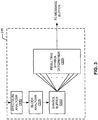
- FIG. 2 is a block diagram of an example implementation of the example decoder 116.
- the example decoder 116 of FIG. 2 includes a sampler 205, a sample buffer 210, a symbol value determiner 215, a message buffer 220, a message identifier 225, a symbol-to-bit converter 230, and a symbol-to-bit reference database 235.
- the example decoder 116 Prior to decoding, receives an audio signal from the microphone 120 of FIG. 1 and/or from live audio.
- the spectrum analyzer 305 of the illustrated example performs a time domain to frequency domain conversion of the samples stored in the sample buffer 210. For example, each time a new block of samples is added to the sample buffer 210 (and an oldest block of samples is removed), the spectrum analyzer 305 analyzes the samples in the sample buffer 210 to determine the spectrum of the updated sample buffer. The frequency spectrum results determined by the spectrum analyzer 305 are provided to the block analyzer 310 for determining a symbol value. According to the illustrated example, where the audio signal is sampled at 16 kHz, one symbol is embedded across 3,072 samples.
- the example spectrum updater 405 of the illustrated example determines spectrum information for the block of samples in the sample buffer 210 based on the previous spectrum information stored in the spectrum buffer 410, information for the samples that are being added to the sample buffer 210, and the samples being removed from the sample buffer 210. For example, the spectrum updater 405 updates spectrum information in the spectrum buffer 410 each time 16 new samples are added to the sample buffer 210 and 16 oldest samples are removed from the sample buffer 210.
- the example spectrum updater 405 determines amplitude information for frequencies of interest (e.g., frequency indices 1 to K that correspond to any desired frequencies of interest (bins)). Alternatively, the spectrum updater 405 may determine spectrum information for any number of frequencies.
- the spectrum is updated by adding information calculated for new samples and removing information for old samples from the prior spectrum information stored in the spectrum buffer 410.
- This algorithm is computationally efficient by determining spectrum information only for frequencies of interest and by updating spectrum information instead of recalculating a full spectrum each time new samples are added.
- the resulting symbol determiner 320 will have a series of 40 symbol retrievers 705 to retrieve the symbol values in the symbol buffer 315 corresponding to the values of s listed above.
- the series of 40 symbol retrievers 705 then store the retrieved symbol values (e.g., a 7-bit number) into the symbol value storage 710.
- the symbol voter 715 of the illustrated example analyzes the symbol values stored in the symbol value storage 710 and determines a resulting symbol value from the symbol values stored in the symbol value storage 710. According to the illustrated example, the symbol voter 715 determines the most occurring symbol of the symbols stored within the symbol value storage 710 using voting. In some examples, the symbol voter may assign different voting "weight" to different symbol values. For example, the symbol voter 715 may assign greater weight to symbols extracted from long blocks overlapping the first extracted symbol value (e.g., s[0] - s[9]), may assign decreasing weight as the symbol index increases (e.g., as symbols represent earlier times), may assign weights based on a confidence score for the symbol determination, etc.
- 1-7 could be implemented by one or more circuit(s), programmable processor(s), application specific integrated circuit(s) (ASIC(s)), programmable logic device(s) (PLD(s)) and/or field programmable logic device(s) (FPLD(s)), etc.
- ASIC application specific integrated circuit
- PLD programmable logic device
- FPLD field programmable logic device
- FIG. 14 is a flowchart of example machine readable instructions 1400 that may be executed to implement the block analyzer 310 of FIGS. 3 and/or 5 and to implement block 1210 of FIG. 12 .
- the example machine readable instructions 1400 of FIG. 14 begin when the frequency scorer 505 receives spectrum analysis results from the spectrum analyzer 305 (block 1405).
- the frequency scorer 505 then scores the emphasized frequencies in the specified bands of the spectrum (block 1410).
- the reference symbol determiner compares the emphasized frequencies in the specified bands to a reference database to determine a symbol value associated with the emphasized frequencies (block 1415).
- the reference symbol determiner 510 then sends the determined symbol value to the symbol buffer 315 for storage (block 1420).
Landscapes
- Engineering & Computer Science (AREA)
- Physics & Mathematics (AREA)
- Signal Processing (AREA)
- Health & Medical Sciences (AREA)
- Audiology, Speech & Language Pathology (AREA)
- Human Computer Interaction (AREA)
- Computational Linguistics (AREA)
- Acoustics & Sound (AREA)
- Multimedia (AREA)
- Two-Way Televisions, Distribution Of Moving Picture Or The Like (AREA)
- Compression, Expansion, Code Conversion, And Decoders (AREA)
- Signal Processing For Digital Recording And Reproducing (AREA)
- Actuator (AREA)
Abstract
Description
- This disclosure relates generally to identifying media, and, more particularly, to methods and apparatus for performing audio watermark detection and extraction.
- Systems for identifying media (e.g., television (TV) programs, radio programs, commentary, audio/video content, movies, commercials, advertisements, etc.) are useful for determining the identity, source, etc. of presented or accessed media in a variety of media monitoring systems. In some systems, a code is inserted into the audio or video of the media and the code is later detected at one or more monitoring sites when the media is presented. The information payload of the code embedded into the media can include program identification information, source identification information, time of broadcast information, etc. In some examples, the code is implemented as an audio watermark encoded in an audio portion of the media. Information may additionally or alternatively be included in a video portion of the media, in metadata associated with the media, etc.
- Monitoring sites may include locations such as, households, stores, places of business and/or any other public and/or private facilities where media exposure and/or consumption of media is monitored. For example, at an example monitoring site, codes from the audio and/or video are captured and stored. The collected codes may then be sent to a central data collection facility for analysis. In some examples, the central data collection facility, a content provider, or another source may also send secondary media associated with the monitored media to the monitoring site (e.g., to a secondary media presentation device).
- Example methods and apparatus to perform watermark detection and extraction are disclosed. An example method includes sampling a media signal to generate samples, wherein the media signal includes an embedded message; determining a first symbol value for a first block of the samples; determining a second symbol value for a second block of the samples; and determining, using a processor, a resulting symbol value, representative of a part of the embedded message, based on the first symbol value and the second symbol value for the first block of samples and the second block of samples, wherein the first block and the second block partially overlap. In some examples, the method further includes determining a third symbol value for a third block of the samples, the third block of samples being located a multiple of a length of an embedded message prior to the first block of samples, and wherein determining the resulting symbol value is also based on the third symbol value. In some examples, the method further includes determining a fourth symbol value for a fourth block of the samples, the fourth block of samples and the third block of samples partially overlap, and determining the resulting symbol value is also determined based on the third symbol value. In some examples, the method further includes determining a first plurality of symbol values for a first plurality of blocks of samples, each block in the first plurality of blocks of samples being located a multiple of a length of a message prior to the first block of samples, and determining the resulting symbol value is also determined based on the first plurality of symbol values. In some examples, the method further includes determining a second plurality of symbol values for a second plurality of blocks of samples, each member of the second plurality of blocks of samples partly overlapping a member of the first plurality of blocks of samples, and determining the resulting symbol value is also determined based on the second plurality of symbol values.
- In some examples, the method includes determining a third symbol value from a third block of samples, and the resulting symbol value is also determined based on the third symbol value. In some examples, determining the resulting symbol value includes extracting a most occurring symbol value. In some examples, the most occurring symbol value is determined by voting.
- In some examples, the media signal is embedded with a plurality of messages, each message comprising a series of symbols. In some examples, the samples are stored in a buffer. In some examples, the buffer is a circular buffer.
- In some examples, the method includes storing the first symbol value and the second symbol value in a tangible memory, wherein the processor reads the first symbol value and the second symbol value from the tangible memory when determining the resulting symbol value. In some examples, the tangible memory is a circular buffer. In some examples, the first symbol value and the second symbol value are determined by performing a spectral analysis on, respectively, the first block of samples and the second block of samples to determine the first symbol value and the second symbol value. In some examples, the spectral analysis is performed using a fast Fourier transform. In some examples, the media signal is an audio signal. In some examples, the embedded message is embedded as an audio watermark.
- Another example method includes sampling a media signal to generate samples, wherein the media signal includes an embedded message; determining a reference symbol value for a reference block of the samples; determining a first plurality of symbol values for a first plurality of blocks of the samples, wherein each block in the plurality of blocks of the samples is located a multiple of a length of a message, in samples, prior to the reference block of the samples; determining a second plurality of symbol values for a second plurality of blocks of the samples, wherein each member of the second plurality of blocks of the samples partly overlaps a member of the first plurality of blocks of the samples; and determining, using a processor, a resulting symbol value, representative of a part of the embedded message, based on the reference symbol value, the first plurality of symbol values, and the second plurality of symbol values.
- An example system includes a sampler to sample a media signal to generate samples, wherein the media signal includes an embedded message; a first symbol value extractor to determine a first symbol value for a first block of the samples; a second symbol value extractor to determine a second symbol value for a second block of the samples; and a processor to determine a resulting symbol value, representative of a part of the embedded message, based on the first symbol value and the second symbol value for the first and second blocks of samples, wherein the first block of the samples and the second block of the samples partially overlap.
- In some examples, the system further comprises a third symbol value extractor to determine a third symbol value for a third block of the samples, wherein the third block of the samples is located a multiple of a length of an embedded message prior to the first block of the samples, wherein determining the resulting symbol value is also based on the third symbol value. In some examples, the system further comprises a fourth symbol value extractor to determine a fourth symbol value for a fourth block of samples wherein the fourth block of samples and the third block of samples partially overlap, wherein determining the resulting symbol value is also determined based on the third symbol value. In some examples, the system further comprises a first plurality of symbol value extractors to determine a first plurality of symbol values for a first plurality of blocks of samples, wherein each block in the first plurality of blocks of samples is located a multiple of a length of a message prior to the first block of samples, wherein determining the resulting symbol value is also determined based on the first plurality of symbol values. In some examples, the system further comprises a second plurality of symbol value extractors to determine a second plurality of symbol values for a second plurality of blocks of samples, wherein each block in the second plurality of blocks of samples partly overlaps a member of the first plurality of blocks of samples, wherein determining the resulting symbol value is also determined based on the second plurality of symbol values.
- In some examples, the system further comprises a third symbol extractor to determine a third symbol value from a third block of samples, wherein the resulting symbol value is also determined based on the third symbol value. In some examples, determining the resulting symbol value comprises extracting a most occurring symbol value. In some examples, the most occurring symbol value is determined by voting. In some examples, the media signal is embedded with a plurality of messages, wherein each message comprises a series of symbols. In some examples, the sampled media signal is stored in a buffer. In some such examples, the buffer is a circular buffer.
- In some examples, the system comprises a tangible memory to store the first symbol value and the second symbol value, wherein the processor reads the first symbol value and the second symbol value from the tangible memory when determining the resulting symbol value. In some examples, the tangible memory is a circular buffer. In some examples, the first symbol value extractor and the second symbol value extractor perform a spectral analysis on, respectively, the first block of samples and the second block of samples to determine the first symbol value and the second symbol value. In some such examples, the spectral analysis is performed using a fast Fourier transform.
- In some examples, the media signal is an audio signal. In some examples, the embedded message is embedded as an audio watermark. In some examples, Example computer readable storage media comprising instructions, which, when executed cause a machine to perform the disclosed methods are also disclosed.
-
-
FIG. 1 is a block diagram of an example system constructed in accordance with the teachings of this disclosure for identifying media. -
FIG. 2 is a block diagram of the example decoder of the example system ofFIG. 1 . -
FIG. 3 is a block diagram of the example symbol value determiner of the example decoder ofFIG. 2 . -
FIG. 4 is a block diagram of the example spectrum analyzer of the example symbol value determiner ofFIG. 3 . -
FIG. 5 is a block diagram of the example block analyzer of the example symbol value determiner ofFIG. 3 . -
FIG. 6 is a block diagram of the example symbol buffer of the example symbol value determiner ofFIG. 3 . -
FIG. 7 is a block diagram of the resulting symbol determiner of the example symbol value determiner ofFIG. 3 . -
FIG. 8 illustrates example contents of the example symbol buffer ofFIG. 3 . -
FIG. 9 illustrates example message-regions from which an example symbol value determiner may select blocks of samples to determine symbol values. -
FIG. 10 is a magnified view of one of the example message-regions ofFIG. 9 . -
FIG. 11 is a flowchart representative of example machine readable instructions that may be executed to implement the example decoder ofFIGS. 1 and/or 2. -
FIG. 12 is a flowchart representative of example machine readable instructions that may be executed to implement the example symbol value determiner ofFIGS. 2 and/or 3. -
FIG. 13 is a flowchart representative of example machine readable instructions that may be executed to implement the example spectrum analyzer ofFIGS. 3 and/or 4. -
FIG. 14 is a flowchart representative of example machine readable instructions that may be executed to implement the example block analyzer ofFIGS. 3 and/or 5. -
FIG. 15 is a flowchart representative of example machine readable instructions that may be executed to implement the example resulting symbol value determiner ofFIGS. 3 and/or 7. -
FIG. 16 is a flowchart representative of example machine readable instructions that may be executed to implement the example message identifier ofFIG. 2 . -
FIG. 17 is a block diagram of an example processing system that may execute the example machine readable instructions ofFIGS. 11-15 and/or 16, to implement the example decoder ofFIGS. 1 and/or 2, the example sampler ofFIG. 2 , the example sample buffer ofFIG. 2 , the example symbol value determiner ofFIGS. 2 and/or 3, the example spectrum analyzer ofFIGS. 3 and/or 4, the spectrum analyzer ofFIG. 4 , the example slide spectrum buffer ofFIG. 4 , theexample block analyzer 310 ofFIGS. 3 and/or 5, the example frequency scorer ofFIG. 5 , the example reference symbol determiner ofFIG. 5 , the example symbol buffer ofFIGS. 3 and/or 6, the example error detector ofFIG. 6 , the example circular symbol buffer ofFIG. 6 , the example resulting symbol determiner ofFIGS. 3 and/or 7, the example symbol retrievers ofFIG. 7 , the example symbol voter ofFIG. 7 , the example message buffer ofFIG. 2 , the example message identifier ofFIG. 2 , and/or the example symbol-to-bit converter ofFIG. 2 . - In audience measurement systems in which identification information (e.g., a code) is embedded in media (e.g., an audio signal), recovery of the identification information is dependent on the fidelity with which the media is received at the media monitoring site. For example, where the information is embedded by modifying the frequency spectrum of an audio signal, recovery of the code is dependent upon the frequency spectrum being received with sufficient quality to detect the modifications. Interference due to multi-path interference, data transmission interference, sampling artifacts, conversion artifacts, ambient noise, etc. can make it difficult to detect the embedded information. For example, if a microphone is used to receive an encoded audio signal output by a speaker, people talking near the microphone will influence the frequency spectrum of the audio signal. Interference with an audio signal is often transient and may only affect portions of the audio signal.
- Psycho-acoustic masking performed during encoding that attempts to hide the embedded information in the audio to prevent human perception may further complicate decoding of information from audio. In instances where the audio track is quiet or silent, the amplitude of the modifications to the frequency spectrum may be reduced to a point at which detection is difficult or even impossible. In such instances, the effects of interference are further increased. However, in some instances such quiet or silent periods are also transient. For example, speech comprises bursts of audio separated by brief pauses.
- In some instances, the code/watermark and/or the information is represents is used to trigger presentation of additional media (e.g., secondary media presented on a secondary media presentation device such as an iPad®) as discussed in
US Patent Application No. 12/771,640 published asUS Patent Publication No. 2010/0280641 , which is hereby incorporated by reference in its entirety. Therefore, it is desirable to increase the reliability of detection and facilitate consistent detection even when noise, quiet audio, etc. complicate the decoding process. - The following description makes reference to encoding and decoding that is also commonly known as watermarking and watermark detection, respectively. Such watermarking may be performed with audio or video. It should be noted that in this context, audio may be any type of signal having a frequency falling within the normal human audibility spectrum. For example, audio may be speech, music, an audio portion of an audio and/or video program or work (e.g., a television program, a movie, an Internet video, a radio program, a commercial, etc.), a media program, noise, and/or any other sound.
- In general, the encoding of codes in audio involves inserting one and/or more codes or information (e.g., watermarks) into the audio and, ideally, making the code inaudible to hearers of the audio. However, there may be certain situations in which the code may be audible to certain listeners. As described in detail below, the codes or information to be inserted into the audio may be converted into symbols that will be represented by code frequency signals to be embedded in the audio to represent the information. The code frequency signals include one or more code frequencies, wherein different code frequencies or sets of code frequencies are assigned to represent different symbols of information. Any suitable encoding or error correcting technique may be used to convert codes into symbols.
- By controlling the amplitude at which these code frequency signals are input into the native audio, the of the code frequency signals can be made imperceptible to human hearing when the audio in which the code(s) are embedded is played. Accordingly, in some examples, masking operations based on the energy content of the native audio at different frequencies and/or the tonality or noise-like nature of the native audio are used to provide information upon which the amplitude of the code frequency signals is based.
- Additionally, it is possible that an audio signal has passed through a distribution chain. For example, the media may pass from a media originator to a network distributor (e.g., NBC national) and further passed to a local media distributor (e.g., NBC in Chicago). As the audio signal passes through the distribution chain, one of the distributors may encode a watermark into the audio signal in accordance with the techniques described herein, thereby including in the audio signal an indication of identity of that distributor or the time of distribution. The encoding described herein is very robust and, therefore, codes inserted into the audio signal are not easily removed.
- To facilitate reliable and consistent decoding, an example system disclosed herein performs code detection by performing message-region analysis (e.g., analyzing multiple blocks of samples in a vicinity such as blocks of samples that are overlapping and offset by number of samples that is less than the number of samples in a block) on a digitally sampled audio signal. Such decoding takes advantage of the repetition or partial repetition of codes within a signal and/or the fact that portions of a code are embedded over a period of time (e.g., symbols of a message may be embedded in 200 milliseconds of an audio signal during which the multiple attempts at extracting the same symbol can be performed). Accordingly, as disclosed in further detail herein, a decoder selects an initial long block (e.g., a block of samples having a length matching a number of samples previously used by an encoder to encode a symbol) of sampled audio data from which to extract a symbol value. The decoder decodes the initial long block to determine a symbol encoded in the initial long block. The decoder then decodes the symbols identified for a plurality of long blocks preceding and partially overlapping the initial long block. These symbols may have already been extracted by the decoder (e.g., when processing those long blocks as the currently received long block). The overlapping long blocks of samples are in very close proximity in time to the initial long block of samples (thus, within the same message-region) and will likely contain the same symbol value as the initial long block of samples. For example, as described in conjunction with
FIGS. 8 ,9 , and10 , the initial long block of samples may comprise the most recently sampled 3072 samples and a first, prior long block of samples may comprise 3072 samples starting 16 samples prior to the initial long block and excluding the 16 most recently received samples (e.g., a window shifted 16 samples earlier in time). - The decoder may then additionally or alternatively select corresponding message-regions a multiple of a message length of samples earlier in time (as described in conjunction with
FIG. 8 ) from which to select a plurality of overlapping long blocks of samples from which symbol values are extracted. For example, the same message may be repeated (or substantially repeated (e.g., a varying portion such as a timestamp)) every message length, may be repeated every three message lengths, etc. - Once the plurality of symbols is collected, the symbols are compared to determine a resulting symbol associated with the initial block of samples. For example, a voting scheme may be used to determine the most occurring symbol from the results. By using voting or another technique that compares the multiple symbols, the likelihood that interference or masking will prevent symbol extraction is reduced. Transient interference or dropout that affects a minority portion of the symbol extractions will, thus, not prevent symbol decoding.
-
FIG 1 is a block diagram of anexample system 100 constructed in accordance with the techniques of this disclosure for identifying media. Theexample system 100 may be, for example, a television audience measurement system, which is described by way of example herein. Alternatively, thesystem 100 may be any other type of media system. Theexample system 100 ofFIG. 1 includes anencoder 102 that addsinformation 103 to aninput audio signal 104 to produce an encodedaudio signal 105. - The
information 103 may be any information to be associated with theaudio signal 104. For example, theinformation 103 may be representative of a source and/or identity of theaudio signal 104 or a media program associated with the audio signal (e.g., a media program that includes theaudio signal 104 and the video 108). Theinformation 103 may additionally or alternatively include timing information indicative of a time at which theinformation 103 was inserted into the audio and/or a media broadcast time. Theinformation 103 may also include control information to control the behavior of one or more target devices that receive the encodedaudio signal 105. Theaudio signal 104 may be any type of audio including, for example, voice, music, noise, commercial advertisement audio, audio associated with a television program, live performance, etc. While theexample system 100 utilizes an audio signal, any other type of signal may additionally or alternatively be utilized. - The
example encoder 102 ofFIG. 1 may employ any suitable method for inserting theinformation 103 in theaudio signal 104. Theencoder 102 of the illustrated example inserts one or more codes representative of theinformation 103 into theaudio signal 104 to create the encodedaudio 105. Theexample encoder 102 inserts codes into theaudio signal 104 by modifying frequency components of the audio signal 104 (e.g., by combining theaudio signal 104 with sine waves at the frequencies to be modified, by using Fourier coefficients in the frequency domain to adjust amplitudes of certain frequencies of audio, etc.) based on a look-up table of frequency components and symbols. In particular, theencoder 102 of the illustrated example samples theaudio signal 104 at 48 kilohertz (KHz). Each message comprises a synchronization symbol following by 49 bits of information represented by 7 symbols of 7 bits per symbol. In the example ofFIG. 1 , each symbol of a message (including the synchronization symbol) is carried in 9216 samples (a "long block") of audio at 48 KHz, which corresponds to 192 milliseconds of audio. Thus, each message is encoded in 9216 x 8 = 73728 samples, which corresponds to 1.536 seconds of audio. According to the illustrated example, an additional 3072 samples of audio having no encoding ("no code") are left at the end of the message before a new message is encoded. Accordingly, each message and "no code" corresponds to 73728 + 3072 = 76800 samples, which corresponds to 1.6 seconds of audio. Alternatively, any other encoding scheme may be utilized. For example, additional "no code" time may be added such that each message and "no code" corresponds to 2 seconds of audio, each symbol may be encoded in 18432 samples of audio, the audio may be sampled at 96 KHz, and so forth. - In some examples, the
encoder 102 is implemented using, for example, a digital signal processor programmed with instructions to encode theinformation 103. Alternatively, theencoder 102 may be implemented using one or more processors, programmable logic devices, or any suitable combination of hardware, software, and/or firmware. Theencoder 102 may utilize any suitable encoding method. Some example methods, systems, and apparatus to encode and/or decode audio watermarks are disclosed inU.S. Patent Application Serial No. 12/551,220 U.S. Patent Application Serial No. 12/464,811 - The
example transmitter 106 ofFIG. 1 receives an encoded media signal (comprising the encoded audio signal and a video signal 108) and transmits the media signal to thereceiver 110. In the illustrated example, thetransmitter 106 and thereceiver 110 are part of a satellite distribution system. Alternatively, any other type of distribution system may be utilized such as, for example, a wired distribution system, a wireless distribution system, a broadcast system, an on-demand system, a terrestrial distribution system, etc. - Although the distribution system of the
example system 100 includes theencoder 102 and asingle transmitter 106, the distribution system may include additional elements. For example, theaudio signal 104 may be generated at a national network level and distributed to a local network level for local distribution. Accordingly, although theencoder 102 is shown in the transmit lineup prior to thetransmitter 106, one ormore encoders 102 may be additionally or alternatively provided throughout the distribution system of the audio signal 104 (e.g., at the local network level). Thus, theaudio signal 104 may be encoded at multiple levels and may include embedded codes associated with those multiple levels. - After the encoded media signal is received by a
receiver 110, the media is presented by thereceiver 110 or a device associated with the receiver. According to the illustrated example, the encoded audio signal of the encoded media signal is presented via speaker(s) 114 and/or is output on aline 118. The encoded media signal may be presented using elements such as a display to present video content. Thereceiver 110 may be any type of media receiver such as a set top box, a satellite receiver, a cable television receiver, a radio, a television, a computing device, a digital video recorder, etc. While the encoded media signal is presented by thereceiver 110 of the illustrated example upon receipt, presentation of the encoded media signal may be delayed by, for example, time shifting, space shifting, buffering, etc. - When the encoded media signal is presented to an audience, the decoder receives the encoded audio signal via the
line 118 and/or by amicrophone 120 that receives the audio output by the speaker(s) 114. Thedecoder 116 processes the encoded audio signal to extract theinformation 103 represented by the codes embedded in the encoded audio signal. According to the illustrated example, thedecoder 116 samples the encoded audio signal, analyzes the encoded audio signal in the frequency domain to identify frequency components that have been modified (e.g., amplified) by theencoder 102, and determines code symbols corresponding to the modified frequency components. Theexample decoder 116 transmits extracted information to a central facility for processing (e.g., to generate audience measurement report(s) using information retrieved from multiple monitoring sites). Thedecoder 116 may be integrated with an audience measurement meter, may be integrated with areceiver 110, may be integrated with another receiver, may be included in a portable metering device, and/or included in a media presentation device, etc. Thedecoder 116 of the illustrated example determines a most likely symbol at a given instance by analyzing symbols determined for preceding instances as described in conjunction withFIG. 2 below. - The
system 100 of the illustrated example may be utilized to identify broadcast media. In such examples, before media is broadcast, theencoder 102 inserts codes indicative of the source of the media, the broadcast time of the media, the distribution channel of the media, and/or any other identifying information. When the media is presented at a monitoring site, the encoded audio of the media is received by a microphone-based platform using free-field detection and processed by thedecoder 116 to extract the codes. The codes are then logged and reported to a central facility for further processing and reporting. The microphone-based decoders may be dedicated, stand-alone devices for audience measurement, and/or may be implemented using cellular telephones and/or any other type(s) of devices having microphones and software to perform the decoding and code logging operations. Alternatively, wire-based systems may be used whenever the encoded media may be received via a hard wired connection. - Additionally or alternatively, the
system 100 of the illustrated example may be utilized to provide secondary media in association with primary media. In such examples, a primary media presentation device (e.g. a television, a radio, a computing device, and/or any other suitable device) associated with thereceiver 110 presents an encoded audio signal as described above. A secondary media presentation device (e.g., a portable media device such as a mobile telephone, a tablet computer, a laptop, etc.) in the vicinity of the presentation receives the encoded audio signal via a microphone. Examples of secondary presentation devices may be, but are not limited to, a desktop computer, a laptop computer, a mobile computing device, a television, a smart phone, a mobile phone, an Apple® iPad®, an Apple® iPhone®, an Apple® iPod®, an Android™ powered computing device, Palm® webOS® computing device, etc. Thedecoder 116 disposed in the secondary media presentation device then processes the audio signal to extract embedded codes and/or samples of the audio signal are transmitted to a remote location to extract the embedded codes. The codes are then used to select secondary media that is transmitted to the secondary media presentation device for presentation. Accordingly, a secondary media presentation device can obtain secondary content associated with the primary content for presentation on the secondary media presentation device. Example methods, systems, and apparatus to provide secondary media associated with primary media are described inU.S. Patent Application Serial No. 12/771,640 -
FIG. 2 is a block diagram of an example implementation of theexample decoder 116. Theexample decoder 116 ofFIG. 2 includes asampler 205, asample buffer 210, asymbol value determiner 215, amessage buffer 220, amessage identifier 225, a symbol-to-bit converter 230, and a symbol-to-bit reference database 235. Prior to decoding, theexample decoder 116 receives an audio signal from themicrophone 120 ofFIG. 1 and/or from live audio. - The
example sampler 205 ofFIG. 2 converts an analog audio signal into a digitally sampled audio signal. Thesampler 205 may be implemented using an analog to digital converter (A/D) or any other suitable technology, to which encoded audio is provided in analog format. Thesampler 205 may operate at any appropriate sampling rate for which the decoder is designed. In some examples, thesampler 205 will not sample the received analog audio signal at the same sampling rate utilized by theencoder 102. A lower sampling rate may be used by thesampler 205 to decrease the computational resources needed by thesampler 205. For example, while theexample encoder 102 ofFIG. 1 samples the audio at 48 kHz, thesampler 205 may sample the audio signal at 16 kHz. In such an example, a "long" block of 9216 samples sampled at 48 kHz comprises 3072 samples when collected at 16 kHz. Theexample sampler 205 stores the sampled audio signal in thesample buffer 210. - The
sample buffer 210 of the illustrated example is implemented by a first in first out circular buffer having a fixed length. Alternatively, thesample buffer 210 may be implemented by any type of buffer or memory and may hold a sampled audio signal of any length (e.g., thesample buffer 210 may store as many samples as memory permits). - The example
symbol value determiner 215 ofFIG. 2 analyzes a block of samples contained within thesample buffer 210 to determine an encoded symbol value. Thesymbol value determiner 215 of the illustrated example analyzes the spectral characteristics of the block of samples (e.g., using a sliding Fourier analysis or any other algorithm) to identify frequencies modified (e.g., by theencoder 102 ofFIG. 1 ), determines a symbol represented by the modified frequencies (e.g., using a look-up table that matches the look-up table used by the encoder 102), and analyzes symbols determined from preceding blocks of samples to determine an identified symbol value for the given block. The analysis of preceding blocks of samples is described in further detail in conjunction withFIG. 3 . The identified symbol value is stored in themessage buffer 220. An example implementation of thesymbol value determiner 215 is described in conjunction withFIG. 3 . - The example message buffer 220 of
FIG. 2 is a circular buffer to store identified symbol values determined by thesymbol value determiner 215. The stored values are analyzed by the message identifier to parse the listing of resulting symbol values into messages (e.g.,information 103 embedded in theaudio signal 104 ofFIG. 1 ). The example message buffer is a first in first out buffer that holds a fixed number of symbols based on the message length. For example, themessage buffer 220 of the illustrated example holds a multiple of the number of symbols contained in a message and the number of slides in a spectrum analysis (e.g., themessage buffer 220 may be 192 x 8 where there are 192 slides or sample block shifts and 8 symbols per message). Alternatively, themessage buffer 220 may be any type(s) of buffer or memory and may hold any number of symbols (e.g., themessage buffer 220 may store as many symbols as memory permits). - The
example message identifier 225 ofFIG. 2 analyzes themessage buffer 220 for a synchronize symbol. When a synchronize symbol is identified, the symbols following the synchronize symbol are output by themessage identifier 225. In addition, the sample index identifying the last audio signal sample processed is output. The messages may be subject to validation, comparison for duplicates, etc. For example, an example process for validating messages that may be utilized in conjunction withmessage identifier 225 is described inU.S. Patent Application Serial No. 12/551,220 . - The example symbol-to-
bit converter 230 receives a message from themessage identifier 225 and converts each symbol of the message to the corresponding data bits of information (e.g., the information 103). The data bits may be any machine language, digital transmission, etc. that may be transmitted. The example symbol-to-bit converter 230 utilizes the example symbol-to-bit reference database 235 that stores a look-up table of symbols to corresponding information. - A block diagram of an example implementation of the
symbol value determiner 215 ofFIG. 2 is illustrated inFIG. 3 . The examplesymbol value determiner 215 includes aspectrum analyzer 305, ablock analyzer 310, asymbol buffer 315, and a resultingsymbol determiner 320. - The
spectrum analyzer 305 of the illustrated example performs a time domain to frequency domain conversion of the samples stored in thesample buffer 210. For example, each time a new block of samples is added to the sample buffer 210 (and an oldest block of samples is removed), thespectrum analyzer 305 analyzes the samples in thesample buffer 210 to determine the spectrum of the updated sample buffer. The frequency spectrum results determined by thespectrum analyzer 305 are provided to theblock analyzer 310 for determining a symbol value. According to the illustrated example, where the audio signal is sampled at 16 kHz, one symbol is embedded across 3,072 samples. Because the exact boundaries of the symbol are not known, thespectrum analyzer 305 analyzes the incoming audio by sliding through the samples (e.g., analyzing blocks of samples as new samples are slid into a buffer and old samples are slid out of a buffer) to perform a spectrum analyzer each time new samples are received (e.g., 16 samples at a time). Accordingly, it takes 192 slides to move through 3,072 samples resulting in 192 frequency spectrums to be analyzed by theblock analyzer 310. - The
example block analyzer 310 ofFIG. 3 receives the spectrum of frequencies provided by the slidingspectrum analyzer 305 and determines a symbol value for the spectrum of the block of samples. In some examples, theblock analyzer 310 processes the results of the spectral analysis to detect the power of predetermined frequency bands and compares the results with a reference database to determine the symbol value based on the spectrum. The block analyzer then reports the determined symbol value to thesymbol buffer 315 for storage. An example implementation of theblock analyzer 310 is described in greater detail below inFIG. 5 . - The
symbol buffer 315 stores, in chronological order, the symbol values determined by theblock analyzer 310. In some examples thesymbol buffer 315 is a first in first out circular buffer. For example, thesymbol buffer 315 may store a history of symbols to facilitate comparison of a most recently determined symbol with previously determined symbols. An example implementation of thesample buffer 315 is further detailed inFIG. 6 . - The resulting
symbol determiner 320 of the illustrated example compares multiple symbol values in thesymbol buffer 315 to determine a resulting symbol value. For example, each time a new symbol is added to thesymbol buffer 315, the resultingsymbol determiner 320 extracts the new symbol, the 9 symbols immediately preceding the new symbol (e.g., the 9 symbols determined during the previous 9 slides of the spectrum analyzer 305), the 10 symbols determined at one message length earlier in thesymbol buffer 315, the 10 symbols determined at two message lengths earlier in thesymbol buffer 315, and the 10 symbols determined at three message lengths earlier in thesymbol buffer 315 as described in further detail in conjunction withFIG. 8 . The resultingsymbol determiner 320 then identifies the most frequently occurring symbol of the 40 determined symbols as the resulting symbol for the newest added symbol. The resulting symbol is output to themessage buffer 220. - An example block diagram of the
spectrum analyzer 305 ofFIG. 3 is illustrated inFIG. 4 . Thespectrum analyzer 305 ofFIG. 4 includes aspectrum updater 405 to update spectrum information in a spectrum buffer following receipt of a set of samples (e.g., 16 incoming samples). - The
example spectrum updater 405 of the illustrated example determines spectrum information for the block of samples in thesample buffer 210 based on the previous spectrum information stored in thespectrum buffer 410, information for the samples that are being added to thesample buffer 210, and the samples being removed from thesample buffer 210. For example, thespectrum updater 405 updates spectrum information in thespectrum buffer 410 each time 16 new samples are added to thesample buffer 210 and 16 oldest samples are removed from thesample buffer 210. Theexample spectrum updater 405 determines amplitude information for frequencies of interest (e.g.,frequency indices 1 to K that correspond to any desired frequencies of interest (bins)). Alternatively, thespectrum updater 405 may determine spectrum information for any number of frequencies. - The
example spectrum updater 405 determines spectrum information for a frequency of interest k according to the following equation:
sample buffer 210, and fold (q) are the old samples removed from thesample buffer 210. Thus, the spectrum is updated by adding information calculated for new samples and removing information for old samples from the prior spectrum information stored in thespectrum buffer 410. This algorithm is computationally efficient by determining spectrum information only for frequencies of interest and by updating spectrum information instead of recalculating a full spectrum each time new samples are added. To add further efficiency, pre-computed sine and cosine tables may be utilized. These pre-computed values may be obtained as the real and imaginary parts of e
- According to the illustrated example, value of fold (q) are multiplied by a factor to provide stability. The example factor is k 2 = k 1 N , where N is the number of slides used to process a block (e.g., N = 3072 samples per block / 16 samples per slide = 192 - 1 = 191. The factor k 1 may be set to a value close to 1 (e.g., 0.9995) to maintain accuracy. Setting the value to 1 may cause the calculation to be unstable. Thus, according to the illustrated example, k 2 = 0.9995191 = 0.908. Any other factor(s) may be utilized or the factor may not be included in stability is not an issue.
- While an example implementation of the
spectrum analyzer 305 is described in conjunction withFIG. 4 , any other technique for determining spectrum information (e.g., amplitudes of frequencies of interest), may be utilized by thespectrum analyzer 305. For example, thespectrum analyzer 305 may perform a Fourier transform, a sliding Fourier transform, or any other technique. - A block diagram of an example implementation of the
block analyzer 310 is illustrated inFIG. 5 . Theblock analyzer 310 ofFIG. 5 includes afrequency scorer 505, a reference symbol determiner 510, and areference symbol LUT 515. - The
example frequency scorer 505 receives spectrum information from thespectrum analyzer 305. Thefrequency scorer 505 determines which frequencies in predefined frequency bands are emphasized in the spectrum analysis. According to the illustrated example, thefrequency scorer 505 may assign indices to bins within each frequency band, determine which bin in each band has the largest amplitude, and output the index of the bin as a resulting score for that band. For example, frequency bins may be indexed from 0 to 4607 and may be separated by 5.208 Hz. However, only a subset of the frequency bins may be used for storing encoded information. Theexample frequency scorer 505 performs this operation on each frequency band in the subset (i.e., the predefined bands) and outputs the indices of the emphasized bins to the reference symbol determiner 510. - The example reference symbol determiner 510 receives indices of the emphasized bins from the
frequency scorer 505. According to the illustrated example, the reference symbol determiner 510 compares the indices of the emphasized bins with information stored in thereference symbol LUT 515 to determine a symbol corresponding to the emphasized bins. The reference symbol determiner 510 outputs the resulting symbol to thesymbol buffer 315. If no match is found, the reference symbol determiner 510 of the illustrated example outputs an error symbol or provides other notification. -
FIG. 6 is a block diagram illustrating an example implementation of thesymbol buffer 315 ofFIG. 3 . Theexample symbol buffer 315 ofFIG. 6 includes anexample error detector 605 and an examplecircular symbol buffer 610. - The
example error detector 605 ofFIG. 6 identifies input that does not conform to the symbol protocol or format that thesymbol determiner 215 is programmed to read. In some examples, theerror detector 605 may read an error message passed by an earlier element in the analysis (e.g. the reference symbol determiner 510 ofFIG. 5 , as described above). In some examples, the error detector may generate its own error message because the input symbol is non-conforming data (e.g., based on previous detected symbols, based on detecting a symbol that is not in use, etc.). - The
circular symbol buffer 610 of the illustrated example is a circular buffer that is accessed by the resultingsymbol determiner 320 ofFIG. 3 . In the illustrated example, thecircular symbol buffer 610 has the following parameters: - Lm = the number of spectrum analysis slides in one message length and any non-encoded audio following the message within the message interval,

- N = number of consecutive messages stored by the
circular symbol buffer 610,
- s[0] = most recently stored symbol value and
- s[n + NLm ] = oldest stored symbol value.
- An example implementation of the resulting
symbol determiner 320 ofFIG. 3 is illustrated inFIG. 7 . The example resultingsymbol determiner 320 ofFIG. 7 includes a series of example symbol retrievers 705, asymbol value storage 710, and asymbol voter 715. Although a plurality of symbol retrievers 705 are included in the illustrated example, the resultingsymbol determiner 320 may alternatively include fewer or one symbol retriever 705 that retrieve(s) multiple symbols. - The series of symbol retrievers 705 of the illustrated example retrieve a collection of symbols for analysis. For example, according to the illustrated example, the series of symbol retrievers 705 retrieve the most recently received 10 symbols: s[0] - s[9], the 10 symbols that are one message length prior to the most recently received 10 symbols: s[0+Lm] - s[9+Lm], the 10 symbols that are two message lengths prior to the most recently received 10 symbols: s[0+2Lm] - s[9+2Lm], and the 10 symbols that are three message lengths prior to the most recently received 10 symbols: s[0+3Lm] - s[9+3Lm. Such a retrieval approach takes advantage of the understanding that the 10 consecutive symbols (e.g., symbols determined for 10 partially overlapping sets corresponding to slides by 16 samples each) are likely to include the same embedded code. In addition, the retrieval approach takes advantage of the understanding that symbols that are one message length away are likely to be the same where most or all of the symbols of a message are repeatedly encoded in an audio signal. In other implementations, different groups of symbols may be analyzed. For example, if it is determined that the same message is encoded every 5 messages, then the symbols spaced 5 message lengths apart should be compared. Additionally, more of fewer consecutive symbols may be retrieved. For example, more consecutive symbols may be selected if the number of samples in each slide of the spectral analysis is decreased, if the number of samples corresponding to a symbol encoding is increased, and/or if the sampling rate is decreased.
- According to the example of
FIG. 7 :
s[0] = first symbol value
o = one less than the number of consecutive overlapping blocks separated by one slide or shift. M represents the set of locations at prior messages to be analyzed, which are the points in the symbol buffer to extract symbol values for message-region analysis. For example, a sample set for M is provided below to illustrate the formation of the series s for analyzing the current message and the three preceding messages:

symbol value storage 710. - Returning to the example signal sampled at 16 kHz in which each slide comprises 16 samples and the resulting
symbol determiner 320 analyzes ten consecutive sets of samples overlapping by one slide (i.e., overlapping by 16 samples), wherein s[0] is the first block, thus:
symbol determiner 320 evaluates ten overlapping blocks at message regions three, six, and nine message lengths prior to the first symbol value. For example, messages may be spaced sufficiently far apart (e.g., 3 messages/4.8 seconds apart or any other separation) to enable additional messages to be inserted by other parties or at other levels of the media distribution chain. Thus:


symbol determiner 320 will have a series of 40 symbol retrievers 705 to retrieve the symbol values in thesymbol buffer 315 corresponding to the values of s listed above. Theexample symbol buffer 315 may store 4 messages across 4800 samples (including the separation), which is 4 x 4800 = 19200 total symbols. The series of 40 symbol retrievers 705 then store the retrieved symbol values (e.g., a 7-bit number) into thesymbol value storage 710. - The
symbol value storage 710 of the illustrated example may be implemented by any appropriate temporary or permanent storage which may receive input from the series of symbol retrievers 705 and be accessed by thesymbol voter 715. - The
symbol voter 715 of the illustrated example analyzes the symbol values stored in thesymbol value storage 710 and determines a resulting symbol value from the symbol values stored in thesymbol value storage 710. According to the illustrated example, thesymbol voter 715 determines the most occurring symbol of the symbols stored within thesymbol value storage 710 using voting. In some examples, the symbol voter may assign different voting "weight" to different symbol values. For example, thesymbol voter 715 may assign greater weight to symbols extracted from long blocks overlapping the first extracted symbol value (e.g., s[0] - s[9]), may assign decreasing weight as the symbol index increases (e.g., as symbols represent earlier times), may assign weights based on a confidence score for the symbol determination, etc. -
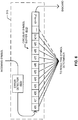
FIG. 8 illustrates an example implementation of thecircular symbol buffer 610 in which a pre-determined set of symbol values is stored in the buffer. Thecircular symbol buffer 610 ofFIG. 8 stores a symbol value for a series of long blocks of samples in which each long block of samples overlaps the prior long block of samples. In the present example:
Lm = a constant representing the length in samples of one message plus any non-encoded audio following the message within the message interval
Recall that M represents the series of message-regions to be analyzed to determine a symbol value. In this example, the message-regions located one, two, and three message lengths (Lm ) prior to s[0] are selected. In this example, the symbol values to be analyzed are shown at each message-region. -
FIG. 9 is an illustration, in the time domain, of example message-regions from which symbol values ofFIG. 8 are extracted from long blocks of samples targeted for analysis. In the interest of clarity, the waveform of the discrete time audio signal y[t] is omitted from the illustration. Each period oftime 904a-d illustrates the period of time tM needed to embed a message in an audio signal. - The message-
regions 902a-d illustrate the portions of the audio signal from which the symbol values ofFIG. 8 used to determine a resulting symbol value originate. For example, message-region 902a corresponds to the region beginning at s[0] and containing the series s[0,1,2,...9]. Likewise, 902b, 902c, and 902d correspond to s[0+ LM], s[0+ 2LM], and s[0+ 3LM] respectively. -
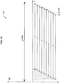
FIG. 10 is a magnified illustration, in the time domain, of the example message-region 902a. As inFIG. 9 , in the interest of clarity, the waveform of the discrete time audio signal y[t] is omitted from the illustration. Themessage region 902a includes 10 overlapping long blocks of samples (bo - b9). Each long block overlaps the previous long block by thegap 1005.Gap 1005 is the same amount of samples as a slide of samples used by thespectrum analyzer 305. In other words, block b0 overlaps the preceding block bl by all but the newest samples retrieved and the oldest samples removed. - While an example manner of implementing the
example decoder 116 ofFIG. 1 has been illustrated inFIG. 2 , an example manner of implementing thesymbol value determiner 215 ofFIG. 2 has been illustrated inFIG. 3 , example manners of implementing thespectrum analyzer 305, theblock analyzer 310, thesymbol buffer 315, and the resultingsymbol determiner 320 have been illustrated inFIGS. 3-6 , and an example manner of implementing the resulting symbol value determiner has been illustrated inFIG. 7 , one or more of the elements, processes and/or devices illustrated inFIGS. 1-7 may be combined, divided, re-arranged, omitted, eliminated and/or implemented in any other way. Further, theexample decoder 116, theexample sampler 205, theexample sample buffer 210, the examplesymbol value determiner 215, theexample message buffer 220, theexample message identifier 225, the example symbol-to-bit converter 230, theexample spectrum analyzer 305, theexample block analyzer 310, theexample symbol buffer 315, the example resultingsymbol determiner 320, theexample spectrum updater 405, the exampleslide spectrum buffer 410, theexample frequency scorer 505, the example reference symbol determiner 510, theexample error detector 605, the examplecircular symbol buffer 610, the example symbol retrievers 705, and theexample symbol voter 715 ofFIGS. 1-7 may be implemented by hardware, software, firmware and/or any combination of hardware, software and/or firmware. Thus, theexample sampler 205, theexample sample buffer 210, the examplesymbol value determiner 215, theexample message buffer 220, theexample message identifier 225, the example symbol-to-bit converter 230, theexample spectrum analyzer 305, theexample block analyzer 310, theexample symbol buffer 315, the example resultingsymbol determiner 320, theexample spectrum updater 405, the exampleslide spectrum buffer 410, theexample frequency scorer 505, the example reference symbol determiner 510, theexample error detector 605, the examplecircular symbol buffer 610, the example symbol retrievers 705, and/or theexample symbol voter 715 and/or, more generally, thedecoder 116 ofFIGS. 1-7 or any other block ofFIGS. 1-7 could be implemented by one or more circuit(s), programmable processor(s), application specific integrated circuit(s) (ASIC(s)), programmable logic device(s) (PLD(s)) and/or field programmable logic device(s) (FPLD(s)), etc. When any of the apparatus or system claims of this patent are read to cover a purely software and/or firmware implementation, at least one of theexample sampler 205, theexample sample buffer 210, the examplesymbol value determiner 215, theexample message buffer 220, theexample message identifier 225, the example symbol-to-bit converter 230, theexample spectrum analyzer 305, theexample block analyzer 310, theexample symbol buffer 315, the example resultingsymbol determiner 320, theexample spectrum updater 405, the exampleslide spectrum buffer 410, theexample frequency scorer 505, the example reference symbol determiner 510, theexample error detector 605, the examplecircular symbol buffer 610, the example symbol retrievers 705, and/or theexample symbol voter 715 and/or, more generally, thedecoder 116 ofFIGS. 1-7 are hereby expressly defined to include a tangible computer readable medium such as a memory, DVD, CD, Blu-ray, etc. storing the software and/or firmware. Further still, theexample sampler 205, theexample sample buffer 210, the examplesymbol value determiner 215, theexample message buffer 220, theexample message identifier 225, the example symbol-to-bit converter 230, theexample spectrum analyzer 305, theexample block analyzer 310, theexample symbol buffer 315, the example resultingsymbol determiner 320, theexample spectrum updater 405, the exampleslide spectrum buffer 410, theexample frequency scorer 505, the example reference symbol determiner 510, theexample error detector 605, the examplecircular symbol buffer 610, the example symbol retrievers 705, and/or theexample symbol voter 715 and/or, more generally, thedecoder 116 ofFIGS. 1-7 may include one or more elements, processes and/or devices in addition to, or instead of, those illustrated inFIG. 1-7 , and/or may include more than one of any or all of the illustrated elements, processes and devices. - Flowcharts representative of example machine readable instructions for implementing the
example decoder 116, theexample symbol determiner 215, theexample spectrum analyzer 305, theexample block analyzer 310, theexample symbol buffer 315, the example resultingsymbol determiner 320, and theexample message identifier 225 are shown inFIGS. 11-16 . In these examples, the machine readable instructions comprise program(s) for execution by a processor such as theprocessor 1712 shown in theexample processing platform 1700 discussed below in connection withFIG. 17 . The program may be embodied in software stored on a tangible computer readable medium such as a CD-ROM, a floppy disk, a hard drive, a digital versatile disk (DVD), a Blu-ray disk, or a memory associated with theprocessor 1712, but the entire program and/or parts thereof could alternatively be executed by a device other than theprocessor 1712 and/or embodied in firmware or dedicated hardware. Further, although the example programs are described with reference to the flowcharts illustrated inFIGS. 11-16 , many other methods of implementing, theexample decoder 116, theexample symbol determiner 215, theexample spectrum analyzer 305, theexample block analyzer 310, theexample symbol buffer 315, the example resultingsymbol determiner 320, and theexample message identifier 225 may alternatively be used. For example, the order of execution of the blocks may be changed, and/or some of the blocks described may be changed, eliminated, or combined. - As mentioned above, the example processes of
FIGS. 11-16 may be implemented using coded instructions (e.g., computer readable instructions) stored on a tangible computer readable medium such as a hard disk drive, a flash memory, a read-only memory (ROM), a compact disk (CD), a digital versatile disk (DVD), a cache, a random-access memory (RAM) and/or any other storage media in which information is stored for any duration (e.g., for extended time periods, permanently, brief instances, for temporarily buffering, and/or for caching of the information). As used herein, the term tangible computer readable medium is expressly defined to include any type of computer readable storage device and/or storage disc, and to exclude propagating signals. Additionally or alternatively, the example processes ofFIGS. 11-16 may be implemented using coded instructions (e.g., computer readable instructions) stored on a non-transitory computer readable medium such as a hard disk drive, a flash memory, a read-only memory, a compact disk, a digital versatile disk, a cache, a random-access memory and/or any other storage media in which information is stored for any duration (e.g., for extended time periods, permanently, brief instances, for temporarily buffering, and/or for caching of the information). As used herein, the term non-transitory computer readable medium is expressly defined to include any type of computer readable device and/or storage disk, and to exclude propagating signals. As used herein, when the phrase "at least" is used as the transition term in a preamble of a claim, it is openended in the same manner as the term "comprising" is open ended. Thus, a claim using "at least" as the transition term in its preamble may include elements in addition to those expressly recited in the claim. -
FIG. 11 is a flowchart of example machinereadable instructions 1100 that may be executed to implement thedecoder 116 ofFIGS. 1 and/or 2. With reference toFIGS. 1 and/or 2, the example machinereadable instructions 1100 ofFIG. 11 begin execution when thesampler 205 samples the audio portion of a media signal including an embedded message (block 1105). The sampled audio signal is stored in the sample buffer 210 (block 1110). Thesymbol value determiner 215 determines symbol values from the sampled signal (block 1115). The symbol values determined by thesymbol value determiner 215 are stored within the message buffer 220 (block 1120). A message is determined by themessage identifier 225 from the values stored within the message buffer 220 (block 1125). The message is converted to bits by the symbol-to-bit converter 230 using the symbol-to-bit reference database 235 (block 1130). -
FIG. 12 is a flowchart of example machinereadable instructions 1200 that may be executed to implement thesymbol value determiner 215 ofFIGS. 2 and/or 3 and to implementblock 1115 of the flowchart ofFIG. 11 . With reference toFIGS. 2 and/or 3, the example machinereadable instructions 1200 ofFIG. 12 begin when thespectrum analyzer 305 determines a spectrum for a long block of samples stored in the sample buffer 210 (block 1205). Theblock analyzer 310 determines a symbol value using the spectrum of the long block of samples (block 1210). The determined symbol value is then stored in the symbol buffer (block 1215).Blocks symbol buffer 315. The resultingsymbol determiner 320 then determines a resulting symbol value from symbol values stored in the symbol buffer (block 1220). -
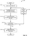
FIG. 13 is a flowchart of example machinereadable instructions 1300 that may be executed to implement thespectrum analyzer 305 ofFIGS. 3 and/or 4 and to implementblock 1205 ofFIG. 12 . With reference toFIGS. 3 and4 , the example machine readable instructions begin execution atblock 1305 at which thespectrum updater 405 detects and receives a newly gathered set of samples (e.g., following the additional of 16 new samples to the sample buffer 210) (block 1305). Thespectrum updater 405 updates spectrum information for a particular frequency (e.g., a first frequency of interest or bin) in view of the newly added samples and samples removed from the sample buffer 210 (e.g., using the technique described in conjunction withFIG. 4 ) (block 1310). Thespectrum updater 405 stores the updated frequency information (e.g., amplitude information for the frequency of interest) in the spectrum buffer 410 (block 1315). Thespectrum updater 405 determines if there are additional frequencies to be analyzed (block 1320). When there are additional frequencies to be analyzed, thespectrum updater 405 selects the next frequency and control returns to block 1310 to determine spectrum information for the next frequency (block 1325). - When there are no additional frequencies to be analyzed (block 1320), the
spectrum updater 405 sends the spectrum information in thespectrum buffer 410 to the block analyzer 310 (block 1330). -
FIG. 14 is a flowchart of example machinereadable instructions 1400 that may be executed to implement theblock analyzer 310 ofFIGS. 3 and/or 5 and to implementblock 1210 ofFIG. 12 . With reference toFIGS. 3 and/or 5, the example machinereadable instructions 1400 ofFIG. 14 begin when thefrequency scorer 505 receives spectrum analysis results from the spectrum analyzer 305 (block 1405). Thefrequency scorer 505 then scores the emphasized frequencies in the specified bands of the spectrum (block 1410). The reference symbol determiner compares the emphasized frequencies in the specified bands to a reference database to determine a symbol value associated with the emphasized frequencies (block 1415). The reference symbol determiner 510 then sends the determined symbol value to thesymbol buffer 315 for storage (block 1420). -
FIG. 15 is a flowchart of example machinereadable instructions 1500 that may be executed to implement the resultingsymbol determiner 320 ofFIGS. 3 and/or 7 and to implementblock 1220 ofFIG. 12 . With reference toFIGS. 3 and/or 7, the example machinereadable instructions 1500 ofFIG. 7 when the resultingsymbol determiner 320 determines a series of symbol values to retrieve for analysis from the symbol buffer (block 1505). The series of symbols to retrieve may be configured by an administrator of the resultingsymbol determiner 320. For example, the user may indicate that the resultingsymbol determiner 320 should consider the most recently identified symbol, the 9 symbols immediately preceding the most recently identified symbol, and the 10 corresponding symbols from each of preceding 3 messages. The set of symbol retrievers 705 retrieve the selected symbol values for analysis from the symbol buffer 315 (block 1510). The symbol retrievers 705 store all retrieved symbol values in the symbol value storage 710 (block 1515). Thesymbol voter 715 determines the most occurring symbol within the symbol value storage 710 (block 1520). Thesymbol voter 715 then outputs the most occurring symbol value to the message buffer 220 (block 1525). -
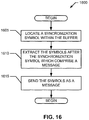
FIG 16 is a flowchart of example machinereadable instructions 1600 that may be executed to implement themessage identifier 225 ofFIG. 2 and to implementblock 1125 ofFIG. 11 . With reference toFIG. 2 , the example machinereadable instructions 1600 begin when themessage identifier 225 locates a synchronization symbol within the message buffer 220 (block 1605). Themessage buffer 220 extracts the number of symbols of a message after the synchronization symbol (block 1610). The message identifier sends the extracted symbols to the symbol-to-bit converter 230 (block 1615). -
FIG. 17 is a block diagram of anexample processor platform 1700 capable of executing the instructions ofFIGS. 11-16 to implement the apparatus ofFIGS. 1-7 . Theprocessor platform 1700 can be, for example, a server, a personal computer, a mobile phone (e.g., a cell phone), a personal digital assistant (PDA), an Internet appliance, a DVD player, a CD player, a digital video recorder, a Blu-ray player, a gaming console, a personal video recorder, a set top box, or any other type of computing device. - The
processor platform 1700 of the instant example includes aprocessor 1712. For example, theprocessor 1712 can be implemented by one or more microprocessors or controllers from any desired family or manufacturer. - The
processor 1712 includes a local memory 1713 (e.g., a cache) and is in communication with a main memory including avolatile memory 1716 and anon-volatile memory 1714 via abus 1718. Thevolatile memory 1716 may be implemented by Synchronous Dynamic Random Access Memory (SDRAM), Dynamic Random Access Memory (DRAM), RAMBUS Dynamic Random Access Memory (RDRAM) and/or any other type of random access memory device. Thenon-volatile memory 1714 may be implemented by flash memory and/or any other desired type of memory device. Access to themain memory - The
processor platform 1700 also includes aninterface circuit 1720. Theinterface circuit 1720 may be implemented by any type of interface standard, such as an Ethernet interface, a universal serial bus (USB), and/or a PCI express interface. - One or
more input devices 1722 are connected to theinterface circuit 1720. The input device(s) 1722 permit a user to enter data and commands into theprocessor 1712. The input device(s) can be implemented by, for example, a keyboard, a mouse, a touchscreen, a track-pad, a trackball, isopoint and/or a voice recognition system. - One or
more output devices 1724 are also connected to theinterface circuit 1720. Theoutput devices 1724 can be implemented, for example, by display devices (e.g., a liquid crystal display, a cathode ray tube display (CRT), a printer and/or speakers). Theinterface circuit 1720, thus, typically includes a graphics driver card. - The
interface circuit 1720 also includes a communication device such as a modem or network interface card to facilitate exchange of data with external computers via a network 1726 (e.g., an Ethernet connection, a digital subscriber line (DSL), a telephone line, coaxial cable, a cellular telephone system, etc.). - The
computer 1700 also includes one or moremass storage devices 1728 for storing software and data. Examples of suchmass storage devices 1728 include floppy disk drives, hard drive disks, compact disk drives and digital versatile disk (DVD) drives. Themass storage device 1728 may implement theexample sample buffer 210, theexample message buffer 220, the example symbol-to-bit reference database 235, theexample symbol buffer 315, the exampleslide spectrum buffer 410, the examplereference symbol LUT 515, the examplecircular symbol buffer 610, the examplesymbol value storage 710, and/or any other storage element. - The coded
instructions 1732 ofFIGS. 11-17 may be stored in themass storage device 1728, in thevolatile memory 1714, in thenon-volatile memory 1716, and/or on a removable storage medium such as a CD or DVD. - From the foregoing, it will be appreciated that the above disclosed methods, apparatus and articles of manufacture improves upon prior methods of decoding embedded codes by exploiting the redundancy in analyzing overlapping blocks of samples and/or by exploiting the redundancy of recurring symbols in messages consecutively encoded in media.
- Although certain example methods, apparatus and articles of manufacture have been described herein, the scope of coverage of this patent is not limited thereto. On the contrary, this patent covers all methods, apparatus and articles of manufacture fairly falling within the scope of the claims of this patent.

3072 samples per symbol x 8 symbols/16 samples per slide + 7424 samples/ 16 samples per slide = 2000 sets.
Claims (15)
- An apparatus comprising:memory; andat least one processor to execute computer readable instructions to:determine a reference symbol value for a reference block of samples of a media signal;obtain a first plurality of symbol values determined for a first plurality of blocks of samples of the media signal, ones of the first plurality of blocks of samples to partially overlap the reference block of samples;obtain a second plurality of symbol values determined for a second plurality of blocks of samples of the media signal, ones of the second plurality of blocks of samples related to corresponding ones of the first plurality of blocks of samples by a multiple of a message length; anddetermine an output symbol value based on a comparison of the reference symbol value, the ones of the first plurality of symbol values, and the ones of the second plurality of symbol values, the output symbol value representative of a portion of a message embedded in the media signal.
- The apparatus of claim 1, wherein the ones of the first plurality of blocks of samples partially overlap the reference block of samples based on corresponding different sample block shifts relative to the reference block of samples.
- The apparatus of claim 1 or claim 2, wherein the message length is based on a length of the message embedded in the media signal.
- The apparatus of any one of claim 1 to 3, wherein the comparison is based on a voting scheme.
- The apparatus of claim 4, wherein the at least one processor is to weight the reference symbol value, the ones of the first plurality of symbol values, and the ones of the second plurality of symbol values before the comparison based on the voting scheme is performed.
- The apparatus of claim 5, wherein the at least one processor is to:assign a first weight to the reference symbol value and the ones of the first plurality of symbol values; andassign a second weight to the ones of the second plurality of symbol values.
- The apparatus of claim 6, wherein the first weight is larger than the second weight.
- A method comprising:determining, with at least one processor, a reference symbol value for a reference block of samples of a media signal;obtaining a first plurality of symbol values determined for a first plurality of blocks of samples of the media signal, ones of the first plurality of blocks of samples partially overlapping the reference block of samples;obtaining a second plurality of symbol values determined for a second plurality of blocks of samples of the media signal, ones of the second plurality of blocks of samples related to corresponding ones of the first plurality of blocks of samples by a multiple of a message length; anddetermining, with the at least one processor, an output symbol value based on a comparison of the reference symbol value, the ones of the first plurality of symbol values, and the ones of the second plurality of symbol values, the output symbol value representative of a portion of a message embedded in the media signal.
- The method of claim 8, wherein the ones of the first plurality of blocks of samples partially overlap the reference block of samples based on corresponding different sample block shifts relative to the reference block of samples.
- The method of claim 8 or claim 9, wherein the message length is based on a length of the message embedded in the media signal.
- The method of any one of claim 8 to 10, wherein the comparison is based on a voting scheme.
- The method of claim 11, further including weighting the reference symbol value, the ones of the first plurality of symbol values, and the ones of the second plurality of symbol values before performing the comparison based on the voting scheme.
- The method of claim 12, wherein the weighting includes:assigning a first weight to the reference symbol value and the ones of the first plurality of symbol values; andassigning a second weight to the ones of the second plurality of symbol values.
- The method of claim 13, wherein the first weight is larger than the second weight.
- At least one computer readable medium comprising computer readable instructions that, when executed, cause the at least one processor to perform the method of any one or claims 8 to 14.
Applications Claiming Priority (3)
| Application Number | Priority Date | Filing Date | Title |
|---|---|---|---|
| US13/653,001 US9368123B2 (en) | 2012-10-16 | 2012-10-16 | Methods and apparatus to perform audio watermark detection and extraction |
| PCT/US2013/060187 WO2014062332A1 (en) | 2012-10-16 | 2013-09-17 | Methods and apparatus to perform audio watermark detection and extraction |
| EP13846852.5A EP2910027B1 (en) | 2012-10-16 | 2013-09-17 | Methods and apparatus to perform audio watermark detection and extraction |
Related Parent Applications (1)
| Application Number | Title | Priority Date | Filing Date |
|---|---|---|---|
| EP13846852.5A Division EP2910027B1 (en) | 2012-10-16 | 2013-09-17 | Methods and apparatus to perform audio watermark detection and extraction |
Publications (2)
| Publication Number | Publication Date |
|---|---|
| EP3846163A1 true EP3846163A1 (en) | 2021-07-07 |
| EP3846163B1 EP3846163B1 (en) | 2026-02-25 |
Family
ID=50475356
Family Applications (2)
| Application Number | Title | Priority Date | Filing Date |
|---|---|---|---|
| EP21158661.5A Active EP3846163B1 (en) | 2012-10-16 | 2013-09-17 | Methods and apparatus to perform audio watermark detection and extraction |
| EP13846852.5A Active EP2910027B1 (en) | 2012-10-16 | 2013-09-17 | Methods and apparatus to perform audio watermark detection and extraction |
Family Applications After (1)
| Application Number | Title | Priority Date | Filing Date |
|---|---|---|---|
| EP13846852.5A Active EP2910027B1 (en) | 2012-10-16 | 2013-09-17 | Methods and apparatus to perform audio watermark detection and extraction |
Country Status (6)
| Country | Link |
|---|---|
| US (1) | US9368123B2 (en) |
| EP (2) | EP3846163B1 (en) |
| JP (1) | JP2014081076A (en) |
| AU (1) | AU2013332371B2 (en) |
| CA (1) | CA2887703C (en) |
| WO (1) | WO2014062332A1 (en) |
Families Citing this family (12)
| Publication number | Priority date | Publication date | Assignee | Title |
|---|---|---|---|---|
| US10973656B2 (en) | 2009-09-18 | 2021-04-13 | Spinal Surgical Strategies, Inc. | Bone graft delivery system and method for using same |
| US9479216B2 (en) * | 2014-07-28 | 2016-10-25 | Uvic Industry Partnerships Inc. | Spread spectrum method and apparatus |
| US10271107B2 (en) * | 2015-11-26 | 2019-04-23 | The Nielsen Company (Us), Llc | Accelerated television advertisement identification |
| US10062134B2 (en) | 2016-06-24 | 2018-08-28 | The Nielsen Company (Us), Llc | Methods and apparatus to perform symbol-based watermark detection |
| US10347262B2 (en) | 2017-10-18 | 2019-07-09 | The Nielsen Company (Us), Llc | Systems and methods to improve timestamp transition resolution |
| US10448122B1 (en) | 2018-07-02 | 2019-10-15 | The Nielsen Company (Us), Llc | Methods and apparatus to extend a timestamp range supported by a watermark |
| US10448123B1 (en) | 2018-07-02 | 2019-10-15 | The Nielsen Company (Us), Llc | Methods and apparatus to extend a timestamp range supported by a watermark |
| CN110047497B (en) * | 2019-05-14 | 2021-06-11 | 腾讯科技(深圳)有限公司 | Background audio signal filtering method and device and storage medium |
| US12211514B2 (en) * | 2021-03-30 | 2025-01-28 | Jio Platforms Limited | System and method for facilitating data transmission through audio waves |
| US20230084574A1 (en) * | 2021-09-16 | 2023-03-16 | UncommonX Inc. | Bit sequence storage method and system |
| US11564003B1 (en) * | 2021-09-20 | 2023-01-24 | The Nielsen Company (Us), Llc | Systems, apparatus, and methods to improve watermark detection in acoustic environments |
| US12537803B2 (en) | 2023-09-29 | 2026-01-27 | Bank Of America Corporation | Using tonal bits for secure messaging |
Citations (2)
| Publication number | Priority date | Publication date | Assignee | Title |
|---|---|---|---|---|
| WO2010048459A1 (en) * | 2008-10-24 | 2010-04-29 | The Nielsen Company (Us), Llc | Methods and apparatus to perform audio watermarking and watermark detection and extraction |
| US20100280641A1 (en) | 2009-05-01 | 2010-11-04 | David Henry Harkness | Methods, apparatus and articles of manufacture to provide secondary content in association with primary broadcast media content |
Family Cites Families (25)
| Publication number | Priority date | Publication date | Assignee | Title |
|---|---|---|---|---|
| US3232182A (en) * | 1963-08-15 | 1966-02-01 | John F Gilbert | Hydraulic pressure compensating means for internal combustion engine systems |
| US3683752A (en) * | 1970-09-17 | 1972-08-15 | Anthony Eugene Joseph Martin | Multiposition fluid-operable piston and cylinder unit |
| JPS5378774U (en) * | 1976-12-03 | 1978-06-30 | ||
| US20020009208A1 (en) * | 1995-08-09 | 2002-01-24 | Adnan Alattar | Authentication of physical and electronic media objects using digital watermarks |
| US5768426A (en) | 1993-11-18 | 1998-06-16 | Digimarc Corporation | Graphics processing system employing embedded code signals |
| US6424725B1 (en) | 1996-05-16 | 2002-07-23 | Digimarc Corporation | Determining transformations of media signals with embedded code signals |
| US6614914B1 (en) | 1995-05-08 | 2003-09-02 | Digimarc Corporation | Watermark embedder and reader |
| JPH08259191A (en) * | 1995-03-20 | 1996-10-08 | Osaka Jack Seisakusho:Kk | Hydraulic jack with mechanical locking mechanism in both directions |
| JP3686741B2 (en) | 1997-02-19 | 2005-08-24 | 富士通株式会社 | Identification information embedding method in image data, identification information extraction method from image data in which identification information is embedded, identification information embedding device in image data, identification information extraction device from image data in which identification information is embedded, and computer Readable medium |
| AUPO521897A0 (en) | 1997-02-20 | 1997-04-11 | Telstra R & D Management Pty Ltd | Invisible digital watermarks |
| JPH1160171A (en) * | 1997-08-08 | 1999-03-02 | Berubitsuku:Kk | Hydraulic cylinder device |
| US6285775B1 (en) | 1998-10-01 | 2001-09-04 | The Trustees Of The University Of Princeton | Watermarking scheme for image authentication |
| US6871180B1 (en) * | 1999-05-25 | 2005-03-22 | Arbitron Inc. | Decoding of information in audio signals |
| WO2002039714A2 (en) | 2000-11-08 | 2002-05-16 | Digimarc Corporation | Content authentication and recovery using digital watermarks |
| US7131007B1 (en) * | 2001-06-04 | 2006-10-31 | At & T Corp. | System and method of retrieving a watermark within a signal |
| EP1421521A2 (en) | 2001-07-31 | 2004-05-26 | Gracenote, Inc. | Multiple step identification of recordings |
| US7231061B2 (en) * | 2002-01-22 | 2007-06-12 | Digimarc Corporation | Adaptive prediction filtering for digital watermarking |
| US7319791B1 (en) | 2003-09-22 | 2008-01-15 | Matrox Electronic Systems, Ltd. | Subtractive primitives used in pattern matching |
| WO2007109531A2 (en) * | 2006-03-17 | 2007-09-27 | University Of Rochester | Watermark synchronization system and method for embedding in features tolerant to errors in feature estimates at receiver |
| US20100158160A1 (en) | 2008-12-24 | 2010-06-24 | Qualcomm Incorporated | Extracting information from positioning pilot channel symbols in forward link only system |
| US8676570B2 (en) | 2010-04-26 | 2014-03-18 | The Nielsen Company (Us), Llc | Methods, apparatus and articles of manufacture to perform audio watermark decoding |
| JP5554658B2 (en) | 2010-08-06 | 2014-07-23 | Kddi株式会社 | Audio digital watermark embedding apparatus and program |
| EP2439735A1 (en) | 2010-10-06 | 2012-04-11 | Thomson Licensing | Method and Apparatus for generating reference phase patterns |
| EP2487680B1 (en) | 2011-12-29 | 2014-03-05 | Distribeo | Audio watermark detection for delivering contextual content to a user |
| US8768710B1 (en) * | 2013-12-05 | 2014-07-01 | The Telos Alliance | Enhancing a watermark signal extracted from an output signal of a watermarking encoder |
-
2012
- 2012-10-16 US US13/653,001 patent/US9368123B2/en active Active
-
2013
- 2013-09-17 EP EP21158661.5A patent/EP3846163B1/en active Active
- 2013-09-17 CA CA2887703A patent/CA2887703C/en active Active
- 2013-09-17 WO PCT/US2013/060187 patent/WO2014062332A1/en not_active Ceased
- 2013-09-17 AU AU2013332371A patent/AU2013332371B2/en not_active Ceased
- 2013-09-17 EP EP13846852.5A patent/EP2910027B1/en active Active
- 2013-10-04 JP JP2013208696A patent/JP2014081076A/en active Pending
Patent Citations (2)
| Publication number | Priority date | Publication date | Assignee | Title |
|---|---|---|---|---|
| WO2010048459A1 (en) * | 2008-10-24 | 2010-04-29 | The Nielsen Company (Us), Llc | Methods and apparatus to perform audio watermarking and watermark detection and extraction |
| US20100280641A1 (en) | 2009-05-01 | 2010-11-04 | David Henry Harkness | Methods, apparatus and articles of manufacture to provide secondary content in association with primary broadcast media content |
Non-Patent Citations (2)
| Title |
|---|
| "Repetition code", INTERNET CITATION, 17 December 2009 (2009-12-17), pages 1 - 4, XP002654975, Retrieved from the Internet <URL:http://en.wikipedia.org/w/index.php?title=Repetition_code&oldid=401957146> [retrieved on 20110801] * |
| CAGATAY KARABAT ED - HYOUNG-JOONG KIM ET AL: "Adaptive Threshold Based Robust Watermark Detection Method", 10 November 2008, DIGITAL WATERMARKING, SPRINGER BERLIN HEIDELBERG, BERLIN, HEIDELBERG, PAGE(S) 139 - 151, ISBN: 978-3-642-04437-3, XP019131144 * |
Also Published As
| Publication number | Publication date |
|---|---|
| EP2910027B1 (en) | 2021-02-24 |
| EP2910027A4 (en) | 2016-06-29 |
| JP2014081076A (en) | 2014-05-08 |
| CA2887703C (en) | 2018-12-04 |
| AU2013332371B2 (en) | 2016-08-11 |
| CA2887703A1 (en) | 2014-04-24 |
| EP2910027A1 (en) | 2015-08-26 |
| US20140105448A1 (en) | 2014-04-17 |
| WO2014062332A1 (en) | 2014-04-24 |
| AU2013332371A1 (en) | 2015-05-07 |
| EP3846163B1 (en) | 2026-02-25 |
| US9368123B2 (en) | 2016-06-14 |
Similar Documents
| Publication | Publication Date | Title |
|---|---|---|
| EP3846163B1 (en) | Methods and apparatus to perform audio watermark detection and extraction | |
| US12189684B2 (en) | Methods and apparatus to perform audio watermarking and watermark detection and extraction | |
| CA2875289C (en) | Methods and apparatus for identifying media | |
| AU2009308304B2 (en) | Methods and apparatus to perform audio watermarking and watermark detection and extraction | |
| AU2013203838B2 (en) | Methods and apparatus to perform audio watermarking and watermark detection and extraction | |
| AU2013203674B2 (en) | Methods and apparatus to perform audio watermarking and watermark detection and extraction |
Legal Events
| Date | Code | Title | Description |
|---|---|---|---|
| PUAI | Public reference made under article 153(3) epc to a published international application that has entered the european phase |
Free format text: ORIGINAL CODE: 0009012 |
|
| STAA | Information on the status of an ep patent application or granted ep patent |
Free format text: STATUS: THE APPLICATION HAS BEEN PUBLISHED |
|
| AC | Divisional application: reference to earlier application |
Ref document number: 2910027 Country of ref document: EP Kind code of ref document: P |
|
| AK | Designated contracting states |
Kind code of ref document: A1 Designated state(s): AL AT BE BG CH CY CZ DE DK EE ES FI FR GB GR HR HU IE IS IT LI LT LU LV MC MK MT NL NO PL PT RO RS SE SI SK SM TR |
|
| STAA | Information on the status of an ep patent application or granted ep patent |
Free format text: STATUS: REQUEST FOR EXAMINATION WAS MADE |
|
| 17P | Request for examination filed |
Effective date: 20220107 |
|
| RBV | Designated contracting states (corrected) |
Designated state(s): AL AT BE BG CH CY CZ DE DK EE ES FI FR GB GR HR HU IE IS IT LI LT LU LV MC MK MT NL NO PL PT RO RS SE SI SK SM TR |
|
| STAA | Information on the status of an ep patent application or granted ep patent |
Free format text: STATUS: EXAMINATION IS IN PROGRESS |
|
| 17Q | First examination report despatched |
Effective date: 20230428 |
|
| GRAP | Despatch of communication of intention to grant a patent |
Free format text: ORIGINAL CODE: EPIDOSNIGR1 |
|
| STAA | Information on the status of an ep patent application or granted ep patent |
Free format text: STATUS: GRANT OF PATENT IS INTENDED |
|
| INTG | Intention to grant announced |
Effective date: 20251010 |
|
| GRAS | Grant fee paid |
Free format text: ORIGINAL CODE: EPIDOSNIGR3 |
|
| GRAA | (expected) grant |
Free format text: ORIGINAL CODE: 0009210 |
|
| STAA | Information on the status of an ep patent application or granted ep patent |
Free format text: STATUS: THE PATENT HAS BEEN GRANTED |
|
| AC | Divisional application: reference to earlier application |
Ref document number: 2910027 Country of ref document: EP Kind code of ref document: P |
|
| AK | Designated contracting states |
Kind code of ref document: B1 Designated state(s): AL AT BE BG CH CY CZ DE DK EE ES FI FR GB GR HR HU IE IS IT LI LT LU LV MC MK MT NL NO PL PT RO RS SE SI SK SM TR |
|
| REG | Reference to a national code |
Ref country code: CH Ref legal event code: F10 Free format text: ST27 STATUS EVENT CODE: U-0-0-F10-F00 (AS PROVIDED BY THE NATIONAL OFFICE) Effective date: 20260225 Ref country code: GB Ref legal event code: FG4D |
|
| REG | Reference to a national code |
Ref country code: DE Ref legal event code: R096 Ref document number: 602013087356 Country of ref document: DE |
|
| REG | Reference to a national code |
Ref country code: IE Ref legal event code: FG4D |