EP3845960B1 - Display apparatus - Google Patents
Display apparatus Download PDFInfo
- Publication number
- EP3845960B1 EP3845960B1 EP20217713.5A EP20217713A EP3845960B1 EP 3845960 B1 EP3845960 B1 EP 3845960B1 EP 20217713 A EP20217713 A EP 20217713A EP 3845960 B1 EP3845960 B1 EP 3845960B1
- Authority
- EP
- European Patent Office
- Prior art keywords
- cover
- display apparatus
- speaker
- magnet
- sheet
- Prior art date
- Legal status (The legal status is an assumption and is not a legal conclusion. Google has not performed a legal analysis and makes no representation as to the accuracy of the status listed.)
- Active
Links
Images




Classifications
-
- G—PHYSICS
- G02—OPTICS
- G02F—OPTICAL DEVICES OR ARRANGEMENTS FOR THE CONTROL OF LIGHT BY MODIFICATION OF THE OPTICAL PROPERTIES OF THE MEDIA OF THE ELEMENTS INVOLVED THEREIN; NON-LINEAR OPTICS; FREQUENCY-CHANGING OF LIGHT; OPTICAL LOGIC ELEMENTS; OPTICAL ANALOGUE/DIGITAL CONVERTERS
- G02F1/00—Devices or arrangements for the control of the intensity, colour, phase, polarisation or direction of light arriving from an independent light source, e.g. switching, gating or modulating; Non-linear optics
- G02F1/01—Devices or arrangements for the control of the intensity, colour, phase, polarisation or direction of light arriving from an independent light source, e.g. switching, gating or modulating; Non-linear optics for the control of the intensity, phase, polarisation or colour
- G02F1/13—Devices or arrangements for the control of the intensity, colour, phase, polarisation or direction of light arriving from an independent light source, e.g. switching, gating or modulating; Non-linear optics for the control of the intensity, phase, polarisation or colour based on liquid crystals, e.g. single liquid crystal display cells
- G02F1/133—Constructional arrangements; Operation of liquid crystal cells; Circuit arrangements
- G02F1/1333—Constructional arrangements; Manufacturing methods
- G02F1/133308—Support structures for LCD panels, e.g. frames or bezels
- G02F1/133314—Back frames
-
- G—PHYSICS
- G02—OPTICS
- G02F—OPTICAL DEVICES OR ARRANGEMENTS FOR THE CONTROL OF LIGHT BY MODIFICATION OF THE OPTICAL PROPERTIES OF THE MEDIA OF THE ELEMENTS INVOLVED THEREIN; NON-LINEAR OPTICS; FREQUENCY-CHANGING OF LIGHT; OPTICAL LOGIC ELEMENTS; OPTICAL ANALOGUE/DIGITAL CONVERTERS
- G02F1/00—Devices or arrangements for the control of the intensity, colour, phase, polarisation or direction of light arriving from an independent light source, e.g. switching, gating or modulating; Non-linear optics
- G02F1/01—Devices or arrangements for the control of the intensity, colour, phase, polarisation or direction of light arriving from an independent light source, e.g. switching, gating or modulating; Non-linear optics for the control of the intensity, phase, polarisation or colour
- G02F1/13—Devices or arrangements for the control of the intensity, colour, phase, polarisation or direction of light arriving from an independent light source, e.g. switching, gating or modulating; Non-linear optics for the control of the intensity, phase, polarisation or colour based on liquid crystals, e.g. single liquid crystal display cells
- G02F1/133—Constructional arrangements; Operation of liquid crystal cells; Circuit arrangements
- G02F1/1333—Constructional arrangements; Manufacturing methods
- G02F1/133308—Support structures for LCD panels, e.g. frames or bezels
- G02F1/133317—Intermediate frames, e.g. between backlight housing and front frame
-
- G—PHYSICS
- G02—OPTICS
- G02F—OPTICAL DEVICES OR ARRANGEMENTS FOR THE CONTROL OF LIGHT BY MODIFICATION OF THE OPTICAL PROPERTIES OF THE MEDIA OF THE ELEMENTS INVOLVED THEREIN; NON-LINEAR OPTICS; FREQUENCY-CHANGING OF LIGHT; OPTICAL LOGIC ELEMENTS; OPTICAL ANALOGUE/DIGITAL CONVERTERS
- G02F1/00—Devices or arrangements for the control of the intensity, colour, phase, polarisation or direction of light arriving from an independent light source, e.g. switching, gating or modulating; Non-linear optics
- G02F1/01—Devices or arrangements for the control of the intensity, colour, phase, polarisation or direction of light arriving from an independent light source, e.g. switching, gating or modulating; Non-linear optics for the control of the intensity, phase, polarisation or colour
- G02F1/13—Devices or arrangements for the control of the intensity, colour, phase, polarisation or direction of light arriving from an independent light source, e.g. switching, gating or modulating; Non-linear optics for the control of the intensity, phase, polarisation or colour based on liquid crystals, e.g. single liquid crystal display cells
- G02F1/133—Constructional arrangements; Operation of liquid crystal cells; Circuit arrangements
- G02F1/1333—Constructional arrangements; Manufacturing methods
- G02F1/133308—Support structures for LCD panels, e.g. frames or bezels
- G02F1/13332—Front frames
-
- G—PHYSICS
- G02—OPTICS
- G02F—OPTICAL DEVICES OR ARRANGEMENTS FOR THE CONTROL OF LIGHT BY MODIFICATION OF THE OPTICAL PROPERTIES OF THE MEDIA OF THE ELEMENTS INVOLVED THEREIN; NON-LINEAR OPTICS; FREQUENCY-CHANGING OF LIGHT; OPTICAL LOGIC ELEMENTS; OPTICAL ANALOGUE/DIGITAL CONVERTERS
- G02F1/00—Devices or arrangements for the control of the intensity, colour, phase, polarisation or direction of light arriving from an independent light source, e.g. switching, gating or modulating; Non-linear optics
- G02F1/01—Devices or arrangements for the control of the intensity, colour, phase, polarisation or direction of light arriving from an independent light source, e.g. switching, gating or modulating; Non-linear optics for the control of the intensity, phase, polarisation or colour
- G02F1/13—Devices or arrangements for the control of the intensity, colour, phase, polarisation or direction of light arriving from an independent light source, e.g. switching, gating or modulating; Non-linear optics for the control of the intensity, phase, polarisation or colour based on liquid crystals, e.g. single liquid crystal display cells
- G02F1/133—Constructional arrangements; Operation of liquid crystal cells; Circuit arrangements
- G02F1/1333—Constructional arrangements; Manufacturing methods
- G02F1/133308—Support structures for LCD panels, e.g. frames or bezels
- G02F1/133325—Assembling processes
-
- G—PHYSICS
- G06—COMPUTING OR CALCULATING; COUNTING
- G06F—ELECTRIC DIGITAL DATA PROCESSING
- G06F1/00—Details not covered by groups G06F3/00 - G06F13/00 and G06F21/00
- G06F1/16—Constructional details or arrangements
- G06F1/1601—Constructional details related to the housing of computer displays, e.g. of CRT monitors, of flat displays
- G06F1/1605—Multimedia displays, e.g. with integrated or attached speakers, cameras, microphones
-
- H—ELECTRICITY
- H04—ELECTRIC COMMUNICATION TECHNIQUE
- H04N—PICTORIAL COMMUNICATION, e.g. TELEVISION
- H04N5/00—Details of television systems
- H04N5/64—Constructional details of receivers, e.g. cabinets or dust covers
- H04N5/642—Disposition of sound reproducers
-
- H—ELECTRICITY
- H04—ELECTRIC COMMUNICATION TECHNIQUE
- H04N—PICTORIAL COMMUNICATION, e.g. TELEVISION
- H04N5/00—Details of television systems
- H04N5/64—Constructional details of receivers, e.g. cabinets or dust covers
- H04N5/645—Mounting of picture tube on chassis or in housing
-
- H—ELECTRICITY
- H04—ELECTRIC COMMUNICATION TECHNIQUE
- H04R—LOUDSPEAKERS, MICROPHONES, GRAMOPHONE PICK-UPS OR LIKE ACOUSTIC ELECTROMECHANICAL TRANSDUCERS; ELECTRIC HEARING AIDS; PUBLIC ADDRESS SYSTEMS
- H04R1/00—Details of transducers, loudspeakers or microphones
- H04R1/02—Casings; Cabinets ; Supports therefor; Mountings therein
-
- H—ELECTRICITY
- H04—ELECTRIC COMMUNICATION TECHNIQUE
- H04R—LOUDSPEAKERS, MICROPHONES, GRAMOPHONE PICK-UPS OR LIKE ACOUSTIC ELECTROMECHANICAL TRANSDUCERS; ELECTRIC HEARING AIDS; PUBLIC ADDRESS SYSTEMS
- H04R1/00—Details of transducers, loudspeakers or microphones
- H04R1/02—Casings; Cabinets ; Supports therefor; Mountings therein
- H04R1/023—Screens for loudspeakers
-
- H—ELECTRICITY
- H04—ELECTRIC COMMUNICATION TECHNIQUE
- H04R—LOUDSPEAKERS, MICROPHONES, GRAMOPHONE PICK-UPS OR LIKE ACOUSTIC ELECTROMECHANICAL TRANSDUCERS; ELECTRIC HEARING AIDS; PUBLIC ADDRESS SYSTEMS
- H04R1/00—Details of transducers, loudspeakers or microphones
- H04R1/02—Casings; Cabinets ; Supports therefor; Mountings therein
- H04R1/028—Casings; Cabinets ; Supports therefor; Mountings therein associated with devices performing functions other than acoustics, e.g. electric candles
-
- G—PHYSICS
- G02—OPTICS
- G02F—OPTICAL DEVICES OR ARRANGEMENTS FOR THE CONTROL OF LIGHT BY MODIFICATION OF THE OPTICAL PROPERTIES OF THE MEDIA OF THE ELEMENTS INVOLVED THEREIN; NON-LINEAR OPTICS; FREQUENCY-CHANGING OF LIGHT; OPTICAL LOGIC ELEMENTS; OPTICAL ANALOGUE/DIGITAL CONVERTERS
- G02F2201/00—Constructional arrangements not provided for in groups G02F1/00 - G02F7/00
- G02F2201/46—Fixing elements
-
- G—PHYSICS
- G02—OPTICS
- G02F—OPTICAL DEVICES OR ARRANGEMENTS FOR THE CONTROL OF LIGHT BY MODIFICATION OF THE OPTICAL PROPERTIES OF THE MEDIA OF THE ELEMENTS INVOLVED THEREIN; NON-LINEAR OPTICS; FREQUENCY-CHANGING OF LIGHT; OPTICAL LOGIC ELEMENTS; OPTICAL ANALOGUE/DIGITAL CONVERTERS
- G02F2201/00—Constructional arrangements not provided for in groups G02F1/00 - G02F7/00
- G02F2201/46—Fixing elements
- G02F2201/465—Snap -fit
-
- G—PHYSICS
- G02—OPTICS
- G02F—OPTICAL DEVICES OR ARRANGEMENTS FOR THE CONTROL OF LIGHT BY MODIFICATION OF THE OPTICAL PROPERTIES OF THE MEDIA OF THE ELEMENTS INVOLVED THEREIN; NON-LINEAR OPTICS; FREQUENCY-CHANGING OF LIGHT; OPTICAL LOGIC ELEMENTS; OPTICAL ANALOGUE/DIGITAL CONVERTERS
- G02F2201/00—Constructional arrangements not provided for in groups G02F1/00 - G02F7/00
- G02F2201/50—Protective arrangements
- G02F2201/505—Arrangements improving the resistance to acoustic resonance like noise
-
- G—PHYSICS
- G02—OPTICS
- G02F—OPTICAL DEVICES OR ARRANGEMENTS FOR THE CONTROL OF LIGHT BY MODIFICATION OF THE OPTICAL PROPERTIES OF THE MEDIA OF THE ELEMENTS INVOLVED THEREIN; NON-LINEAR OPTICS; FREQUENCY-CHANGING OF LIGHT; OPTICAL LOGIC ELEMENTS; OPTICAL ANALOGUE/DIGITAL CONVERTERS
- G02F2202/00—Materials and properties
- G02F2202/28—Adhesive materials or arrangements
-
- H—ELECTRICITY
- H04—ELECTRIC COMMUNICATION TECHNIQUE
- H04R—LOUDSPEAKERS, MICROPHONES, GRAMOPHONE PICK-UPS OR LIKE ACOUSTIC ELECTROMECHANICAL TRANSDUCERS; ELECTRIC HEARING AIDS; PUBLIC ADDRESS SYSTEMS
- H04R2499/00—Aspects covered by H04R or H04S not otherwise provided for in their subgroups
- H04R2499/10—General applications
- H04R2499/15—Transducers incorporated in visual displaying devices, e.g. televisions, computer displays, laptops
Definitions
- Embodiments of the present disclosure relate to a display apparatus, and more specifically, to a display apparatus having an improved back cover to provide the display apparatus with a slim thickness.
- a display apparatus is an output device that visually displays data information, such as characters or figures, and images
- the display apparatus includes a television, various monitors, and various portable terminals (e.g., notebook computers, tablet personal computers (tablet PCs), and smart phones).
- portable terminals e.g., notebook computers, tablet personal computers (tablet PCs), and smart phones.
- the display apparatus may include a display module including a display panel and a chassis assembly, and a back cover coupled to a rear side of the display module to form a rear appearance of the display apparatus.
- the back cover is formed by injection molding of a metal or plastic material.
- a plastic material facilitates implementing a shape for assembly with a display module, and obviates the need of a separate post-processing, but has a difficulty in implementing a thin thickness due to the characteristics of plastic injection processing.
- Use of a thin metal may cause deformation due to denting or bending during handling, and thus has a difficulty in securing the appearance quality.
- EP 1 372 021 A1 and US 2013/004006 A1 constitutes prior art useful for understanding the invention.
- embodiments of the present disclosure may provide a display apparatus having a back cover that is capable of securing rigidity while having a slim thickness and facilitating assembly with a display module.
- the invention is defined in the appended claims.
- a display apparatus includes: a display module; a main board configured to drive the display module; and a cover coupled to a rear side of the display module such as to cover the display module and the main board, wherein the cover includes: a cover sheet formed of an extruded plastic material or an extruded composite material; and a cover frame attached to the cover sheet and configured to couple the cover sheet to the display module.
- the cover sheet is more flexible than the cover frame.
- the cover frame may include at least one first hook coupling portion that is configured to be coupled to the display module, and the display module may include at least one second hook coupling portion that is configured to be engaged with the at least one first hook coupling portion.
- the at least one first hook coupling portion may be integrally formed with the cover frame.
- the cover frame may include an edge portion having a quadrangular shape and a reinforcing portion extending inward from the edge portion, and the at least one first hook coupling portion may be formed on the edge portion.
- the at least one first hook coupling portion may be a plurality of first hook coupling portions, and the plurality of first hook coupling portions are spaced apart from each other by a predetermined distance in a line lengthwise along the edge portion.
- the display module may include: a display panel; a middle mold configured to support the display panel; a front chassis configured to cover sides of the display panel and sides of the middle mold; and a rear chassis disposed behind the middle mold to support the middle mold, wherein the middle mold includes the at least one second hook coupling portion.
- the display apparatus may further include an adhesive provided between the cover sheet and the cover frame such that the adhesive bonds the cover sheet to the cover frame.
- the adhesive may be a two-component adhesive, a pressure sensitive adhesive (PSA), an ultraviolet (UV) adhesive, or a double-sided tape.
- PSA pressure sensitive adhesive
- UV ultraviolet
- the cover sheet may be formed of the extruded plastic material, and the extruded plastic material includes at least one selected from a group consisting of polycarbonate (PC), polyphenylene ether (PPE), Nylon, polyphenylene sulfide (PPS), polyphthalamide (PPA), acrylonitrile butadiene styrene copolymer (ABS), poly cyclohexylene dimethylene terephthalate glycol (PCTG), and polyethylene terephthalate glycol (PETG).
- PC polycarbonate
- PPE polyphenylene ether
- Nylon polyphenylene sulfide
- PPS polyphthalamide
- ABS acrylonitrile butadiene styrene copolymer
- PCTG poly cyclohexylene dimethylene terephthalate glycol
- PETG polyethylene terephthalate glycol
- the cover sheet may be formed of the extruded composite material, and the extruded composite material includes at least one selected from a group consisting of carbon fiber, glass fiber, mica, montmorillonite, and smectite.
- the display apparatus may further include a speaker installed on a rear surface of the display module, wherein the cover frame may include a third hook coupling portion that is configured to be coupled to the speaker, and the speaker may include a fourth hook coupling portion that is configured to be engaged with the third hook coupling portion.
- the display apparatus may further include a speaker installed on a rear surface of the display module, wherein the speaker may include a speaker magnet installed on a rear surface of the speaker, and the cover sheet may include a sheet magnet installed on a front surface of the cover sheet such that the sheet magnet comes in close contact with the speaker magnet by magnetic attraction.
- the cover sheet may include a speaker hole that is configured to pass sound output from the speaker therethrough, and the sheet magnet may be installed on the front surface of the cover sheet, adjacent to the speaker hole.
- the speaker magnet and the sheet magnet may include a neodymium magnet, a ferrite magnet, a samarium cobalt magnet, or an alnico magnet.
- a display apparatus may include: a display panel that is configured to display an image on a front surface of the display panel; a middle mold configured to support the display panel; a rear chassis coupled to the middle mold such as to support the middle mold; and a cover coupled to a rear side of the rear chassis such as to cover the rear chassis.
- the cover includes: a cover sheet formed of an extruded plastic material or a composite material; and a cover frame attached to the cover sheet.
- the cover frame may be further configured to couple the cover sheet to the middle mold.
- the cover sheet is more flexible than the cover frame.
- the cover frame may include at least one first hook coupling portion that is configured to be coupled to the middle mold, and the middle mold may include at least one second hook coupling portion that is configured to be engaged with the at least one first hook coupling portion.
- the display apparatus may further comprise an adhesive provided between the cover sheet and the cover frame such as to bond the cover sheet to the cover frame.
- a display apparatus includes: a display module and a cover coupled to a rear side of the display module.
- a speaker may be disposed between the display module and the cover.
- the cover includes: a cover sheet formed by an extruded plastic material or an extruded composite material and a cover frame attached to the cover sheet, the cover frame configured to couple the cover sheet to the display module.
- the cover sheet may include a speaker hole that is configured to pass sound output from the speaker therethrough and the cover frame may include an opening corresponding to the speaker hole, wherein the speaker may include a speaker magnet installed on a rear surface of the speaker, and the cover sheet may include a sheet magnet installed on a front surface of the cover sheet such that the sheet magnet comes in close contact with the speaker magnet by magnetic attraction.
- a display apparatus may include: a display module including a display panel; and a cover coupled to a rear side of the display module such as to cover the display module.
- the cover may include: a cover sheet formed of a plastic material or a composite material, and having a plate shape; and a cover frame attached to the cover sheet and configured to couple the cover sheet to the display module.
- the cover frame may include a first coupling body
- the display module may include a second coupling body
- the first coupling body and the second coupling body may be configured to engage together such that the cover sheet is coupled to the display module.
- FIG. 1 the terms “front”, “rear”, “upper”, “lower”, “top”, and “bottom” as herein used are defined with respect to the drawings, but the terms may not restrict the shape and position of the respective components.
- FIG. 1 the X-axis, Y-axis, and Z-axis directions perpendicular to each other are illustrated, the X-axis direction refers to the left and right side direction of the display apparatus, the Y-axis direction refers to the upper and lower side direction of the display apparatus, and the Z-axis direction refers to the front and rear side direction of the display apparatus.
- FIG. 1 is a perspective view illustrating a front appearance of a display apparatus according to an embodiment of the present disclosure.
- FIG. 2 is a perspective view illustrating a rear appearance of the display apparatus of FIG. 1 .
- FIG. 3 is an exploded rear perspective view illustrating the display apparatus of FIG. 1 .
- FIG. 4 is a front perspective view illustrating the display apparatus of FIG. 1 in which a cover is disassembled.
- FIG. 5 is a front perspective view illustrating a cover frame of the display apparatus of FIG. 1 .
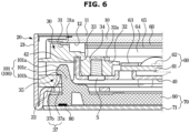
- FIG. 6 is a side cross-sectional view illustrating the display apparatus of FIG. 1 , which shows a lower coupling structure.
- FIG. 7 is a side cross-sectional view illustrating the display apparatus of FIG. 1 , which shows an upper coupling structure.
- a display apparatus 1 may include a television that processes a broadcast image based on broadcast signals, broadcast information, and broadcast data received from a transmission device of a broadcast station.
- the display apparatus 1 is not limited to a television, and may include various devices that can present information, data material, data, etc. as characters, figures, graphs, images, etc., for example, a computer monitor, a mobile phone, an electric signboard, a signage, and the like.
- the display apparatus 1 includes a display module 2 and a cover 70 coupled to a rear side of the display module 2 to form a rear appearance of the display apparatus 1.
- the display module 2 may include a display panel that displays an image.
- the display panel may be implemented as a liquid crystal panel 10.
- the display panel is not limited thereto, and the display panel may be a self-emitting type organic light emitting diode (OLED) panel or a micro LED panel, and in this case, a backlight unit described below may be omitted.
- OLED organic light emitting diode
- the liquid crystal panel 10 may include a thin film transistor (TFT) substrate in which TFTs are formed in a matrix form, a color filter substrate coupled in parallel with the TFT substrate, and liquid crystal molecules interposed between the TFT substrate and the color filter substrate and having a variable optical property depending on a voltage and temperature.
- TFT thin film transistor
- the liquid crystal panel 10 may have a front surface 11 on which an image is displayed, a rear surface 12 formed on the opposite side of the front surface 11, and four side surfaces formed on upper, lower, left, and right sides thereof.
- the display module 2 may include a backlight unit disposed behind the liquid crystal panel 10 to provide light to the liquid crystal panel 10.
- the light source module 60 may be arranged behind the liquid crystal panel 10 in a so-called direct type arrangement. However, unlike the embodiment shown in FIG. 1 , the light source module 60 may be arranged to correspond to at least one side surface of the liquid crystal panel 10 in a so-called edge type arrangement.
- a blue light emitting diode may be used as the light source.
- a cold cathode fluorescent lamp CCFL
- an external electrode fluorescent lamp EEFL
- the optical members may be disposed on a moving path of light emitted from the light source 62 to guide a traveling direction of light or improve optical characteristics.
- the optical members may include a reflector plate 63 to reflect light to prevent loss, a diffusor plate 64 to evenly diffuse irregular light emitted from the light source 62, a quantum dot sheet 65 to improve color reproducibility by changing the wavelength of light, and an optical sheet 66 to improve optical properties.
- the reflector plate 63 may reflect light emitted from the light source 62 or light exiting the diffusor plate 64 rearward to be directed toward the diffusor plate 64.
- the reflector plate 63 may be disposed on the substrate 61 of the light source module 60.
- the diffusor plate 64 may evenly diffuse irregular light generated from the light source 62 and support the quantum dot sheet 65 and the optical sheet 66.
- the quantum dot sheet 65 may be disposed in front of the diffusor plate 64 to be spaced apart from the diffusor plate 64.
- Quantum dots which are semiconductor crystals having a size of several nanometers and emitting light, may be disposed inside the quantum dot sheet 65 in a distributed manner. Quantum dots may receive blue light and generate all colors of visible light according to the size thereof. As the size of the quantum dot is smaller, light with a shorter wavelength may be generated, and as the size of the quantum dot is larger, light with a longer wavelength may be generated.
- the optical sheet 66 may be disposed in front of the diffusor plate 64 to improve optical characteristics of light emitted from the diffusor plate 64.
- the optical sheet 66 may include at least one of a prism sheet that improves luminance by concentrating light, a protection sheet that protects other optical sheets from external impacts or foreign matter inflow, or a reflective polarizing sheet (a dual brightness enhancement film; DBEF) that reflects one polarized light while transmitting other polarized light to improve luminance.
- DBEF dual brightness enhancement film
- the display module 2 may include a chassis assembly that supports and accommodates the liquid crystal panel 10.
- the backlight unit may also be accommodated and supported by the chassis assembly.
- the chassis assembly may include a middle mold 30 supporting the liquid crystal panel 10 and the diffusor plate 64, a front chassis 20 covering sides of the liquid crystal panel 10 and the middle mold 30, and a rear chassis 40 disposed behind the middle mold 30 to support the light source module 60 and the middle mold 30.
- the middle mold 30 may have a frame shape with an opening formed in the center thereof so that light emitted from the light source 62 is incident onto the diffusor plate 64.
- the middle mold 30 may include a panel support surface 31 that supports the liquid crystal panel 10 and a sheet support surface 32 that supports the diffusor plate 64.
- An adhesive 31a may be provided between the panel support surface 31 and the liquid crystal panel 10 so as to bond the panel support surface 31 to the liquid crystal panel 10.
- the adhesive 31a may allow the liquid crystal panel 10 to be bonded to the middle mold 30 without using a separate structure.
- An adhesive 32a may be provided between the sheet support surface 32 and the diffusor plate 64 so as to bond the sheet support surface 32 to the diffusor plate 64.
- the adhesive 32a allows the diffusor plate 64 to be coupled to the middle mold 30 without using a separate structure.
- the middle mold 30 may be coupled to the rear chassis 40 by a screw S. To this end, a screw fastening hole 34 may be formed in the middle mold 30.
- the front chassis 20 may have a frame shape to accommodate the liquid crystal panel 10, the middle mold 30, the backlight unit, and the rear chassis 40.
- the front chassis 20 may include a side portion 21 formed to cover side surfaces of the liquid crystal panel 10, the middle mold 30, the backlight unit, and the rear chassis 40, and a rear portion 22 formed by bending a rear end of the side portion 21.
- the rear chassis 40 may include a base portion 41 supporting the light source module 60 and the middle mold 30 and a bent portion 42 extending forward from an edge of the base portion 41 for coupling with the middle mold 30.
- the bent portion 42 may be inserted into an insertion groove 33 of the middle mold 30.
- the base portion 41 may have a curved plate shape, and may include a light source support portion 41a for supporting the light source module 60 and a middle mold support portion 41b for supporting the middle mold 30.
- the rear chassis 40 may serve to dissipate heat generated from a heat generating element, such as the light source 62, to the outside.
- the rear chassis 40 may be formed of a metal material having high thermal conductivity , such as aluminum or stainless steel (SUS), or a plastic material, such as acrylonitrile butadiene styrene (ABS).
- a main board 47 including at least one electronic component to perform a process for displaying an image signal, and a power supply 48 for supplying power to the display apparatus 1, a driver for allowing an image corresponding to an image signal to be displayed on the liquid crystal panel 10, and a communication module capable of communicating with an external communication device may be provided.
- the main board 47 may include electronic components, such as a chipset, a memory, and the like, and a substrate on which the electronic components are mounted. A wiring or transmission line may be provided on the substrate to electrically connect the electronic components to each other.
- the electronic components may include a tuner for tuning a broadcast signal for each channel and an image processor for processing an image signal.
- the image processor may be provided as individual configurations capable of independently performing each process for processing an image signal, that is, as a group of electronic components, or may be provided as being included in a main System-on-chip (SOC) into which several functions are incorporated.
- the main SoC may include at least one processor that controls the overall operation of the display apparatus 1 and a signal flow between internal components.
- the processor may load a control program to perform a control operation and execute the loaded control program.
- the processor may include at least one of a central processing unit (CPU), a microprocessor, or an application processor (AP).
- CPU central processing unit
- AP application processor
- Signals generated or combined through the image processor may be output to the liquid crystal panel 10 through the driver.
- the driver may be implemented as a control board provided with a timing controller that controls a driving circuit and improves image quality.
- the power supply 48 may supply power to each component constituting the display apparatus 1.
- the power supply 48 may convert commercial alternating current (AC) power input from the outside into power to be supplied to each component of the display apparatus 1, and supply the converted power, and the power supply 48 may include an inverter or a switching mode power supply (SMPS).
- AC alternating current
- SMPS switching mode power supply
- a cover 70 may be coupled to a rear side of the rear chassis 40 to cover the above described various electronic components while forming the rear appearance of the display apparatus 1.
- the cover 70 includes a cover sheet 71 and a cover frame 90 attached to the cover sheet 71 to couple the cover sheet 71 to the display module 2.
- the cover sheet 71 includes a front surface 71a facing the display module 2 and a cover sheet rear surface 71b provided on the opposite side of the front surface 71a to form the rear appearance of the display apparatus 1.
- the cover sheet 71 may be formed by extruding a plastic material to have a slim thickness.
- the cover sheet 71 may be formed with a thin plate shape having the same thickness as a whole.
- the cover sheet 71 may be formed to be flexible.
- the through-holes may include a vent hole 72 for flowing air inside and outside the cover sheet 71, a speaker hole 73 through which sound output from a speaker 50 (e.g., a main speaker) passes, and a bracket installation hole 74 to which a bracket (not shown) is coupled to install the display apparatus 1 on a wall.
- a vent hole 72 for flowing air inside and outside the cover sheet 71
- a speaker hole 73 through which sound output from a speaker 50 (e.g., a main speaker) passes
- a bracket installation hole 74 to which a bracket (not shown) is coupled to install the display apparatus 1 on a wall.
- the through-holes may be formed in the cover sheet 71 by applying a design corresponding to the through-holes to a surface of an extrusion roller, so that through-holes may be implemented at the same time as extrusion.
- polycarbonate (PC), polyphenylene ether (PPE), nylon, polyphenylene sulfide (PPS), polyphthalamide (PPA), acrylonitrile butadiene styrene copolymer (ABS), and poly cyclohexylene dimethylene terephthalate glycol (PCTG)), and polyethylene terephthalate glycol(PETG), etc. may be used.
- cover sheet 71 may be formed by extruding a composite material to reinforce rigidity and increase resistance to heat.
- a composite material carbon fiber, glass fiber, mica, montmorillonite, smectite, etc. may be used.
- the use of the composite material provides a higher rigidity than using plastic, and provides excellent resistance to local impact compared to using metal.
- the cover frame 90 is attached to a front surface of the cover sheet 71 to reinforce the rigidity of the cover sheet 71 while allowing the cover sheet 71 to be coupled to the display module 2.
- the cover frame 90 may be injection-molded of a plastic material, and the cover frame 90 may be formed to be rigid. Accordingly, the cover sheet 71 may be relatively flexible compared to the cover frame 90, and conversely, the cover frame 90 may be relatively rigid compared to the cover sheet 71.
- the cover sheet 71 and the cover frame 90 may be coupled to each other through an adhesive 80.
- an adhesive 80 a two-component adhesive, a pressure sensitive adhesive (PSA), an ultraviolet (UV) adhesive, a double-sided tape, or the like may be used.
- PSA pressure sensitive adhesive
- UV ultraviolet
- the cover frame 90 has a shape corresponding to only a partial area of the cover sheet 71 rather than to the entire area of the cover sheet 71. That is, the cover frame 90 may be provided in a frame shape including an edge portion 91 having a quadrangular-shape and a reinforcing portion 92 extending inward from the edge portion 91 such that openings 96 are formed between the edge portion 91 and the reinforcing portion 92.
- the edge portion 91 may include an upper edge portion 91a, a lower edge portion 91b, a left edge portion 91c, and a right edge portion 91d
- the reinforcing portion 92 may include a central reinforcing portion 93 extending between the upper edge portion 91a and the lower edge portion 91b and side reinforcing portions 94 extending from the left edge portion 91c and the right edge portion 91d.
- a bracket fastening hole 95 corresponding to the bracket installation hole 74 of the cover sheet 71 may be formed in the reinforcing portion 92.
- the thickness of the display apparatus 1 may be provided to be slim.
- the openings 96 of the cover frame 90 may include an opening 96a corresponding to the vent hole 72 of the cover sheet 71 and an opening 96b wider than or corresponding to the speaker hole 73 of the cover sheet 71.
- the cover frame 90 may include a first hook coupling portion 100 for engagement with the display module 2.
- the display module 2 may be provided with a second hook coupling portion 35 to be engaged with the first hook coupling portion 100.
- the cover frame 90 may be engaged with the display module 2 through the first hook coupling portion 100 and the second hook coupling portion 35 without using separate fastening members, such as screws, bolts, nuts, pins, rivets, etc.
- the first hook coupling portion 100 may be integrally formed with the cover frame 90.
- the first hook coupling portion 100 may be formed on the edge portion 91 of the cover frame 90.
- the first hook coupling portion 100 may be formed on the upper edge portion 91a and the lower edge portion 91b that are relatively long.
- the first hook coupling portion 100 may be provided in plural, and the plurality of the first hook coupling portion 100 may be formed to be spaced apart from each other by a predetermined distance in a line lengthwise along the edge portion 91.
- the second hook coupling portion 35 may be formed on the middle mold 30 of the display module 2.
- the second hook coupling portion 35 may be integrally formed with the middle mold 30.
- the second hook coupling portion 35 may be formed at a position corresponding to a position of the first hook coupling portion 100.
- One of the first hook coupling portion 100 and the second hook coupling portion 35 may be a hook, and the other one may be a hook locking portion provided to be locked with the hook.
- the first hook coupling portion 100 formed on the lower edge portion 91b of the cover frame 90 may be a hook 101
- the second hook coupling portion 35 formed on the middle mold 30 to correspond to the first hook coupling portion 100 may be a hook locking portion 37 provided to be locked with the hook 101.
- the hook 101 may include an inclined guide surface 101a, a locking surface 101b, and an elastic portion 101c, and the hook locking portion 37 may include an inclined guide surface 37a and a locking surface 37b.
- the inclined guide surface 101a of the hook 101 and the inclined guide surface 37a of the hook locking portion 38 come in contact with each other, and the elastic portion 101c of the hook 101 may be elastically deformed in an open direction.
- the elastic portion 101c When the hook 101 further advances while the elastic portion 101c is open, the elastic portion 101c is restored by the elastic force, and the locking surface 101b of the hook 101 and the locking surface 37b of the hook locking portion 37 are caused to be locked with each other. Accordingly, the first hook coupling portion 100 and the second hook coupling portion 35 may be engaged with each other.
- the first hook coupling portion 100 formed on the upper edge portion 91a of the cover frame 90 may be a hook locking portion 102
- the second hook coupling portion 35 formed on the middle mold 30 to correspond to the first hook coupling portion 100 may be a hook 36 provided to be locked with the hook locking portion 102.
- the hook 36 may include an inclined guide surface 36a, a locking surface 36b, and an elastic portion 36c
- the hook locking portion 102 may include an inclined guide surface 102a and a locking surface 102b.
- the inclined guide surface 36a of the hook 36 and the inclined guide surface 102a of the hook locking portion 102 come in contact with each other, and the elastic portion 36c of the hook 36 may be elastically deformed in an open direction.
- the elastic portion 36c When the hook 36 further advances while the elastic portion 36c is open, the elastic portion 36c is restored by the elastic force, and the locking surface 36b of the hook 36 and the locking surface 102b of the hook locking portion 102 are caused to be locked with each other. Accordingly, the first hook coupling portion 100 and the second hook coupling portion 35 may be engaged with each other.
- the first hook coupling portion 100 formed on the lower edge portion 91b of the cover frame 90 may be a hook locking portion
- the first hook coupling portion 100 formed on the upper edge portion 91a may be a hook
- the second hook coupling portion 35 formed at a lower portion of the middle mold 30 may be a hook
- the second hook coupling portion 35 formed on an upper portion of the middle mold 30 may be a hook locking portion.
- each of the first hook coupling portion 100 may be a hook and each of the second hook coupling portion 35 may be a hook locking portion, or each of the first hook coupling portion 100 may be a hook locking portion and each of the second hook coupling portion 35 may be a hook.
- the rear chassis 40 may be formed with a through hole 43 through which the hook 36 of the middle mold 30 may pass.
- cover frame 90 being coupled to the middle mold 30 rather than to the rear chassis 40 is that a sufficient distance may need to be secured to ensure smooth deformation and coupling force of the hook, and typically, the rear chassis 40, which may be formed of a metal material, such as aluminum, has poor workability and coupling force of the hook coupling portion, and is liable to be deformed and damaged.
- FIG. 8 is a side cross-sectional view illustrating the display apparatus of FIG. 1 , which shows a coupling structure of an auxiliary speaker and a cover frame.
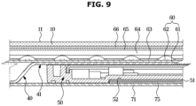
- FIG. 9 is a side cross-sectional view illustrating the display apparatus of FIG. 1 , which shows a coupling structure between a main speaker and a cover sheet using a magnet.
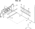
- FIG. 10 is a perspective view illustrating the display apparatus of FIG. 1 , which shows a coupling structure between a main speaker and a cover sheet using a magnet.
- Speakers 50 and 55 may be disposed between the display module 2 and the cover 70. Specifically, the speakers 50 and 55 may be installed on the rear surface 45 of the rear chassis 40.
- the display apparatus 1 may have a structure in which the display module 2 and the cover 70 come in close contact with each other at a portion adjacent to the speakers 50 and 55 to prevent such vibration and noise.
- the cover frame 90 may be directly hook-coupled to the speaker 55.
- the cover frame 90 may include a third hook coupling portion to be coupled to the speaker 55, and the speaker 55 may include a fourth hook coupling portion to be engaged with the third hook coupling portion.
- the third hook coupling portion may be a hook 106
- the fourth hook locking portion corresponding thereto may be a hook locking portion 57 to be engaged with the hook 106.
- the hook 106 may include an inclined guide surface 106a, a locking surface 106b, and an elastic portion 106c, and the hook locking portion 57 may include an inclined guide surface 57a and a locking surface 57b.
- the inclined guide surface 106a of the hook 106 and the inclined guide surface 57a of the hook locking portion 57 come in contact with each other, and the elastic portion 106c of the hook 106 may be elastically deformed in an open direction.
- the hook 106 When the hook 106 further advances while the elastic portion 106c is open, the elastic portion 106c is restored by the elastic force, and the locking surface 106b of the hook 106 and the locking surface 57b of the hook locking portion 57 are caused to be locked with each other. Accordingly, the third hook coupling portion and the fourth hook coupling portion may be engaged with each other.
- the third hook coupling portion may be a hook locking portion
- the fourth hook coupling portion may be a hook corresponding to the hook locking portion
- the speaker 50 includes a speaker magnet 51
- the cover sheet 71 may include a sheet magnet 75 installed on the cover sheet front surface71a of the cover sheet 71 so as to come in close contact with the speaker magnet 51 by magnetic attraction.
- the sheet magnet 75 may be formed at a position corresponding to the position of the speaker magnet 51. That is, the sheet magnet 75 may be formed at a position adjacent to the speaker hole 73. The sheet magnet 75 may be formed adjacent to an upper side and a lower side of the speaker hole 73.
- the sheet magnet 75 may be fixed to the front surface 71a of the cover sheet 71 by various adhesives.
- the speaker 50 may be formed with a magnet installation groove 52 in which the speaker magnet 51 is installed, and the speaker magnet 51 may be inserted into the magnet installation groove 52.
- the speaker magnet 51 and the sheet magnet 75 may include rubber permanent magnets.
- the speaker magnet 51 and the sheet magnet 75 may include a neodymium magnet, a ferrite magnet, a samarium cobalt magnet, or an alnico magnet.
- one of the speaker magnet 51 and the sheet magnet 75 may include a magnet, and the other one may be a magnetic body on which a magnetic attraction of the magnet is exerted.
- the overall thickness of the display apparatus can be reduced by forming the back cover of the display apparatus to be slim.
- the display apparatus can be provided with an improved appearance quality and handling reliability.
- the back cover may be assembled with the display module without using screws, the back cover can be formed slim, and ease of assembly and aesthetic quality can be improved.
Landscapes
- Physics & Mathematics (AREA)
- Nonlinear Science (AREA)
- Engineering & Computer Science (AREA)
- General Physics & Mathematics (AREA)
- Mathematical Physics (AREA)
- Chemical & Material Sciences (AREA)
- Crystallography & Structural Chemistry (AREA)
- Optics & Photonics (AREA)
- Signal Processing (AREA)
- Acoustics & Sound (AREA)
- Multimedia (AREA)
- General Engineering & Computer Science (AREA)
- Theoretical Computer Science (AREA)
- Computer Hardware Design (AREA)
- Human Computer Interaction (AREA)
- Devices For Indicating Variable Information By Combining Individual Elements (AREA)
Description
- This application is based on and claims priority under 35 U.S.C. §119 to
Korean Patent Application No. 10-2020-0000285, filed on January 2, 2020 - Embodiments of the present disclosure relate to a display apparatus, and more specifically, to a display apparatus having an improved back cover to provide the display apparatus with a slim thickness.
- A display apparatus is an output device that visually displays data information, such as characters or figures, and images, and the display apparatus includes a television, various monitors, and various portable terminals (e.g., notebook computers, tablet personal computers (tablet PCs), and smart phones).
- The display apparatus may include a display module including a display panel and a chassis assembly, and a back cover coupled to a rear side of the display module to form a rear appearance of the display apparatus.
- In general, the back cover is formed by injection molding of a metal or plastic material. Use of a plastic material facilitates implementing a shape for assembly with a display module, and obviates the need of a separate post-processing, but has a difficulty in implementing a thin thickness due to the characteristics of plastic injection processing. Use of a thin metal may cause deformation due to denting or bending during handling, and thus has a difficulty in securing the appearance quality.
EP 1 372 021 A1US 2013/004006 A1 constitutes prior art useful for understanding the invention. - Therefore, according to an aspect, embodiments of the present disclosure may provide a display apparatus having a back cover that is capable of securing rigidity while having a slim thickness and facilitating assembly with a display module. The invention is defined in the appended claims.
- Additional aspects of the present disclosure will be set forth in part in the description which follows and, in part, will be obvious from the description, or may be learned by practice of the disclosure.
- According to one or more embodiments, a display apparatus is provided. The display apparatus includes: a display module; a main board configured to drive the display module; and a cover coupled to a rear side of the display module such as to cover the display module and the main board, wherein the cover includes: a cover sheet formed of an extruded plastic material or an extruded composite material; and a cover frame attached to the cover sheet and configured to couple the cover sheet to the display module.
- According to an embodiment, the cover sheet is more flexible than the cover frame.
- According to an embodiment, the cover frame may include at least one first hook coupling portion that is configured to be coupled to the display module, and the display module may include at least one second hook coupling portion that is configured to be engaged with the at least one first hook coupling portion.
- According to an embodiment, the at least one first hook coupling portion may be integrally formed with the cover frame.
- According to an embodiment, the cover frame may include an edge portion having a quadrangular shape and a reinforcing portion extending inward from the edge portion, and the at least one first hook coupling portion may be formed on the edge portion.
- According to an embodiment, the at least one first hook coupling portion may be a plurality of first hook coupling portions, and the plurality of first hook coupling portions are spaced apart from each other by a predetermined distance in a line lengthwise along the edge portion.
- According to an embodiment, the display module may include: a display panel; a middle mold configured to support the display panel; a front chassis configured to cover sides of the display panel and sides of the middle mold; and a rear chassis disposed behind the middle mold to support the middle mold, wherein the middle mold includes the at least one second hook coupling portion.
- According to an embodiment, the display apparatus may further include an adhesive provided between the cover sheet and the cover frame such that the adhesive bonds the cover sheet to the cover frame.
- According to an embodiment, the adhesive may be a two-component adhesive, a pressure sensitive adhesive (PSA), an ultraviolet (UV) adhesive, or a double-sided tape.
- According to an embodiment, the cover sheet may be formed of the extruded plastic material, and the extruded plastic material includes at least one selected from a group consisting of polycarbonate (PC), polyphenylene ether (PPE), Nylon, polyphenylene sulfide (PPS), polyphthalamide (PPA), acrylonitrile butadiene styrene copolymer (ABS), poly cyclohexylene dimethylene terephthalate glycol (PCTG), and polyethylene terephthalate glycol (PETG).
- According to an embodiment, the cover sheet may be formed of the extruded composite material, and the extruded composite material includes at least one selected from a group consisting of carbon fiber, glass fiber, mica, montmorillonite, and smectite.
- According to an embodiment, the display apparatus may further include a speaker installed on a rear surface of the display module, wherein the cover frame may include a third hook coupling portion that is configured to be coupled to the speaker, and the speaker may include a fourth hook coupling portion that is configured to be engaged with the third hook coupling portion.
- According to an embodiment, the display apparatus may further include a speaker installed on a rear surface of the display module, wherein the speaker may include a speaker magnet installed on a rear surface of the speaker, and the cover sheet may include a sheet magnet installed on a front surface of the cover sheet such that the sheet magnet comes in close contact with the speaker magnet by magnetic attraction.
- According to an embodiment, the cover sheet may include a speaker hole that is configured to pass sound output from the speaker therethrough, and the sheet magnet may be installed on the front surface of the cover sheet, adjacent to the speaker hole.
- According to an embodiment, the speaker magnet and the sheet magnet may include a neodymium magnet, a ferrite magnet, a samarium cobalt magnet, or an alnico magnet.
- According to one or more embodiments, a display apparatus is provided. The display apparatus may include: a display panel that is configured to display an image on a front surface of the display panel; a middle mold configured to support the display panel; a rear chassis coupled to the middle mold such as to support the middle mold; and a cover coupled to a rear side of the rear chassis such as to cover the rear chassis. The cover includes: a cover sheet formed of an extruded plastic material or a composite material; and a cover frame attached to the cover sheet. The cover frame may be further configured to couple the cover sheet to the middle mold.
- According to an embodiment, the cover sheet is more flexible than the cover frame.
- According to an embodiment, the cover frame may include at least one first hook coupling portion that is configured to be coupled to the middle mold, and the middle mold may include at least one second hook coupling portion that is configured to be engaged with the at least one first hook coupling portion.
- According to an embodiment, the display apparatus may further comprise an adhesive provided between the cover sheet and the cover frame such as to bond the cover sheet to the cover frame.
- According to one or more embodiments, a display apparatus is provided. The display apparatus includes: a display module and a cover coupled to a rear side of the display module. A speaker may be disposed between the display module and the cover. The cover includes: a cover sheet formed by an extruded plastic material or an extruded composite material and a cover frame attached to the cover sheet, the cover frame configured to couple the cover sheet to the display module. The cover sheet may include a speaker hole that is configured to pass sound output from the speaker therethrough and the cover frame may include an opening corresponding to the speaker hole, wherein the speaker may include a speaker magnet installed on a rear surface of the speaker, and the cover sheet may include a sheet magnet installed on a front surface of the cover sheet such that the sheet magnet comes in close contact with the speaker magnet by magnetic attraction.
- According to one or more embodiments, a display apparatus is provided. The display apparatus may include: a display module including a display panel; and a cover coupled to a rear side of the display module such as to cover the display module. The cover may include: a cover sheet formed of a plastic material or a composite material, and having a plate shape; and a cover frame attached to the cover sheet and configured to couple the cover sheet to the display module.
- According to an embodiment, the cover frame may include a first coupling body, the display module may include a second coupling body, and the first coupling body and the second coupling body may be configured to engage together such that the cover sheet is coupled to the display module.
- These and/or other aspects of the present disclosure will become apparent and more readily appreciated from the following description of embodiments, taken in conjunction with the accompanying drawings of which:
-
FIG. 1 is a perspective view illustrating a front appearance of a display apparatus according to an embodiment of the present disclosure; -
FIG. 2 is a perspective view illustrating a rear appearance of the display apparatus ofFIG. 1 ; -
FIG. 3 is an exploded rear perspective view illustrating the display apparatus ofFIG. 1 ; -
FIG. 4 is a front perspective view illustrating the display apparatus ofFIG. 1 , in which a cover is disassembled; -
FIG. 5 is a front perspective view illustrating a cover frame of the display apparatus ofFIG. 1 ; -
FIG. 6 is a side cross-sectional view illustrating the display apparatus ofFIG. 1 , which shows a lower coupling structure; -
FIG. 7 is a side cross-sectional view illustrating the display apparatus ofFIG. 1 , which shows an upper coupling structure; -
FIG. 8 is a side cross-sectional view illustrating the display apparatus ofFIG. 1 , which shows a coupling structure of an auxiliary speaker and a cover frame; -
FIG. 9 is a side cross-sectional view illustrating the display apparatus ofFIG. 1 , which shows a coupling structure between a main speaker and a cover sheet using a magnet; and -
FIG. 10 is a perspective view illustrating the display apparatus ofFIG. 1 , which shows a coupling structure between a main speaker and a cover sheet using a magnet. - The embodiments set forth herein and illustrated in the present disclosure are only example embodiments and are not representative of the full the technical spirit of the present disclosure, so it should be understood that they may be replaced with various equivalents and modifications at the time of the disclosure.
- The terminology used herein is for the purpose of describing particular embodiments only and is not intended to limit the disclosure. It is to be understood that the singular forms "a," "an," and "the" include plural references unless the context clearly dictates otherwise.
- It will be further understood that the terms "include", "comprise" and/or "have" when used in this specification, specify the presence of stated features, integers, steps, operations, elements, and/or components, but do not preclude the presence or addition of one or more other features, integers, steps, operations, elements, components, and/or groups thereof.
- The terms "front", "rear", "upper", "lower", "top", and "bottom" as herein used are defined with respect to the drawings, but the terms may not restrict the shape and position of the respective components. In
FIG. 1 , the X-axis, Y-axis, and Z-axis directions perpendicular to each other are illustrated, the X-axis direction refers to the left and right side direction of the display apparatus, the Y-axis direction refers to the upper and lower side direction of the display apparatus, and the Z-axis direction refers to the front and rear side direction of the display apparatus. - Hereinafter, embodiments according to the present disclosure will be described in detail with reference to the accompanying drawings.
-
FIG. 1 is a perspective view illustrating a front appearance of a display apparatus according to an embodiment of the present disclosure.FIG. 2 is a perspective view illustrating a rear appearance of the display apparatus ofFIG. 1 .FIG. 3 is an exploded rear perspective view illustrating the display apparatus ofFIG. 1 .FIG. 4 is a front perspective view illustrating the display apparatus ofFIG. 1 in which a cover is disassembled.FIG. 5 is a front perspective view illustrating a cover frame of the display apparatus ofFIG. 1 .FIG. 6 is a side cross-sectional view illustrating the display apparatus ofFIG. 1 , which shows a lower coupling structure.FIG. 7 is a side cross-sectional view illustrating the display apparatus ofFIG. 1 , which shows an upper coupling structure. - Referring to
FIGS. 1 to 7 , adisplay apparatus 1 according to an embodiment may include a television that processes a broadcast image based on broadcast signals, broadcast information, and broadcast data received from a transmission device of a broadcast station. However, thedisplay apparatus 1 is not limited to a television, and may include various devices that can present information, data material, data, etc. as characters, figures, graphs, images, etc., for example, a computer monitor, a mobile phone, an electric signboard, a signage, and the like. - The
display apparatus 1 includes adisplay module 2 and acover 70 coupled to a rear side of thedisplay module 2 to form a rear appearance of thedisplay apparatus 1. - The
display module 2 may include a display panel that displays an image. In the embodiment, the display panel may be implemented as aliquid crystal panel 10. However, the display panel is not limited thereto, and the display panel may be a self-emitting type organic light emitting diode (OLED) panel or a micro LED panel, and in this case, a backlight unit described below may be omitted. - The
liquid crystal panel 10 may include a thin film transistor (TFT) substrate in which TFTs are formed in a matrix form, a color filter substrate coupled in parallel with the TFT substrate, and liquid crystal molecules interposed between the TFT substrate and the color filter substrate and having a variable optical property depending on a voltage and temperature. - The
liquid crystal panel 10 may have afront surface 11 on which an image is displayed, arear surface 12 formed on the opposite side of thefront surface 11, and four side surfaces formed on upper, lower, left, and right sides thereof. - The
display module 2 may include a backlight unit disposed behind theliquid crystal panel 10 to provide light to theliquid crystal panel 10. - The backlight unit may be disposed behind the
liquid crystal panel 10 to radiate light toward theliquid crystal panel 10. The backlight unit may include alight source module 60 including alight source 62 and asubstrate 61 on which thelight source 62 is mounted, and optical members disposed on a moving path of light emitted from thelight source 62. - In the embodiment, the
light source module 60 may be arranged behind theliquid crystal panel 10 in a so-called direct type arrangement. However, unlike the embodiment shown inFIG. 1 , thelight source module 60 may be arranged to correspond to at least one side surface of theliquid crystal panel 10 in a so-called edge type arrangement. - A blue light emitting diode (LED) may be used as the light source. In addition, a cold cathode fluorescent lamp (CCFL) and an external electrode fluorescent lamp (EEFL) may be used as the light source.
- The optical members may be disposed on a moving path of light emitted from the
light source 62 to guide a traveling direction of light or improve optical characteristics. - The optical members may include a
reflector plate 63 to reflect light to prevent loss, adiffusor plate 64 to evenly diffuse irregular light emitted from thelight source 62, aquantum dot sheet 65 to improve color reproducibility by changing the wavelength of light, and anoptical sheet 66 to improve optical properties. - The
reflector plate 63 may reflect light emitted from thelight source 62 or light exiting thediffusor plate 64 rearward to be directed toward thediffusor plate 64. Thereflector plate 63 may be disposed on thesubstrate 61 of thelight source module 60. - The
diffusor plate 64 may evenly diffuse irregular light generated from thelight source 62 and support thequantum dot sheet 65 and theoptical sheet 66. - The
quantum dot sheet 65 may be disposed in front of thediffusor plate 64 to be spaced apart from thediffusor plate 64. Quantum dots, which are semiconductor crystals having a size of several nanometers and emitting light, may be disposed inside thequantum dot sheet 65 in a distributed manner. Quantum dots may receive blue light and generate all colors of visible light according to the size thereof. As the size of the quantum dot is smaller, light with a shorter wavelength may be generated, and as the size of the quantum dot is larger, light with a longer wavelength may be generated. - The
optical sheet 66 may be disposed in front of thediffusor plate 64 to improve optical characteristics of light emitted from thediffusor plate 64. Theoptical sheet 66 may include at least one of a prism sheet that improves luminance by concentrating light, a protection sheet that protects other optical sheets from external impacts or foreign matter inflow, or a reflective polarizing sheet (a dual brightness enhancement film; DBEF) that reflects one polarized light while transmitting other polarized light to improve luminance. - The
display module 2 may include a chassis assembly that supports and accommodates theliquid crystal panel 10. The backlight unit may also be accommodated and supported by the chassis assembly. - The chassis assembly may include a
middle mold 30 supporting theliquid crystal panel 10 and thediffusor plate 64, afront chassis 20 covering sides of theliquid crystal panel 10 and themiddle mold 30, and arear chassis 40 disposed behind themiddle mold 30 to support thelight source module 60 and themiddle mold 30. - The
middle mold 30 may have a frame shape with an opening formed in the center thereof so that light emitted from thelight source 62 is incident onto thediffusor plate 64. Themiddle mold 30 may include apanel support surface 31 that supports theliquid crystal panel 10 and asheet support surface 32 that supports thediffusor plate 64. - An adhesive 31a may be provided between the
panel support surface 31 and theliquid crystal panel 10 so as to bond thepanel support surface 31 to theliquid crystal panel 10. The adhesive 31a may allow theliquid crystal panel 10 to be bonded to themiddle mold 30 without using a separate structure. - An adhesive 32a may be provided between the
sheet support surface 32 and thediffusor plate 64 so as to bond thesheet support surface 32 to thediffusor plate 64. The adhesive 32a allows thediffusor plate 64 to be coupled to themiddle mold 30 without using a separate structure. - The
middle mold 30 may be coupled to therear chassis 40 by a screw S. To this end, ascrew fastening hole 34 may be formed in themiddle mold 30. - The
front chassis 20 may have a frame shape to accommodate theliquid crystal panel 10, themiddle mold 30, the backlight unit, and therear chassis 40. Thefront chassis 20 may include aside portion 21 formed to cover side surfaces of theliquid crystal panel 10, themiddle mold 30, the backlight unit, and therear chassis 40, and arear portion 22 formed by bending a rear end of theside portion 21. - The
rear chassis 40 may include abase portion 41 supporting thelight source module 60 and themiddle mold 30 and abent portion 42 extending forward from an edge of thebase portion 41 for coupling with themiddle mold 30. Thebent portion 42 may be inserted into aninsertion groove 33 of themiddle mold 30. - The
base portion 41 may have a curved plate shape, and may include a lightsource support portion 41a for supporting thelight source module 60 and a middlemold support portion 41b for supporting themiddle mold 30. - The
rear chassis 40 may serve to dissipate heat generated from a heat generating element, such as thelight source 62, to the outside. To this end, therear chassis 40 may be formed of a metal material having high thermal conductivity , such as aluminum or stainless steel (SUS), or a plastic material, such as acrylonitrile butadiene styrene (ABS). - On a
rear surface 45 of therear chassis 40, amain board 47 including at least one electronic component to perform a process for displaying an image signal, and apower supply 48 for supplying power to thedisplay apparatus 1, a driver for allowing an image corresponding to an image signal to be displayed on theliquid crystal panel 10, and a communication module capable of communicating with an external communication device may be provided. - The
main board 47 may include electronic components, such as a chipset, a memory, and the like, and a substrate on which the electronic components are mounted. A wiring or transmission line may be provided on the substrate to electrically connect the electronic components to each other. The electronic components may include a tuner for tuning a broadcast signal for each channel and an image processor for processing an image signal. The image processor may be provided as individual configurations capable of independently performing each process for processing an image signal, that is, as a group of electronic components, or may be provided as being included in a main System-on-chip (SOC) into which several functions are incorporated. The main SoC may include at least one processor that controls the overall operation of thedisplay apparatus 1 and a signal flow between internal components. - The processor may load a control program to perform a control operation and execute the loaded control program. The processor may include at least one of a central processing unit (CPU), a microprocessor, or an application processor (AP).
- Signals generated or combined through the image processor may be output to the
liquid crystal panel 10 through the driver. The driver may be implemented as a control board provided with a timing controller that controls a driving circuit and improves image quality. - The
power supply 48 may supply power to each component constituting thedisplay apparatus 1. Thepower supply 48 may convert commercial alternating current (AC) power input from the outside into power to be supplied to each component of thedisplay apparatus 1, and supply the converted power, and thepower supply 48 may include an inverter or a switching mode power supply (SMPS). - A
cover 70 may be coupled to a rear side of therear chassis 40 to cover the above described various electronic components while forming the rear appearance of thedisplay apparatus 1. - The
cover 70 includes acover sheet 71 and acover frame 90 attached to thecover sheet 71 to couple thecover sheet 71 to thedisplay module 2. - The
cover sheet 71 includes afront surface 71a facing thedisplay module 2 and a cover sheetrear surface 71b provided on the opposite side of thefront surface 71a to form the rear appearance of thedisplay apparatus 1. - The
cover sheet 71 may be formed by extruding a plastic material to have a slim thickness. Thecover sheet 71 may be formed with a thin plate shape having the same thickness as a whole. Thecover sheet 71 may be formed to be flexible. - Through-holes may be formed in the
cover sheet 71. The through-holes may include avent hole 72 for flowing air inside and outside thecover sheet 71, aspeaker hole 73 through which sound output from a speaker 50 (e.g., a main speaker) passes, and abracket installation hole 74 to which a bracket (not shown) is coupled to install thedisplay apparatus 1 on a wall. - The through-holes may be formed in the
cover sheet 71 by applying a design corresponding to the through-holes to a surface of an extrusion roller, so that through-holes may be implemented at the same time as extrusion. - As the plastic materials for the
cover sheet 71, polycarbonate (PC), polyphenylene ether (PPE), nylon, polyphenylene sulfide (PPS), polyphthalamide (PPA), acrylonitrile butadiene styrene copolymer (ABS), and poly cyclohexylene dimethylene terephthalate glycol (PCTG)), and polyethylene terephthalate glycol(PETG), etc. may be used. - In addition, the
cover sheet 71 may be formed by extruding a composite material to reinforce rigidity and increase resistance to heat. As the composite material, carbon fiber, glass fiber, mica, montmorillonite, smectite, etc. may be used. The use of the composite material provides a higher rigidity than using plastic, and provides excellent resistance to local impact compared to using metal. - The
cover frame 90 is attached to a front surface of thecover sheet 71 to reinforce the rigidity of thecover sheet 71 while allowing thecover sheet 71 to be coupled to thedisplay module 2. - The
cover frame 90 may be injection-molded of a plastic material, and thecover frame 90 may be formed to be rigid. Accordingly, thecover sheet 71 may be relatively flexible compared to thecover frame 90, and conversely, thecover frame 90 may be relatively rigid compared to thecover sheet 71. - The
cover sheet 71 and thecover frame 90 may be coupled to each other through an adhesive 80. As the adhesive 80, a two-component adhesive, a pressure sensitive adhesive (PSA), an ultraviolet (UV) adhesive, a double-sided tape, or the like may be used. - The
cover frame 90 has a shape corresponding to only a partial area of thecover sheet 71 rather than to the entire area of thecover sheet 71. That is, thecover frame 90 may be provided in a frame shape including anedge portion 91 having a quadrangular-shape and a reinforcingportion 92 extending inward from theedge portion 91 such thatopenings 96 are formed between theedge portion 91 and the reinforcingportion 92. - The
edge portion 91 may include anupper edge portion 91a, alower edge portion 91b, aleft edge portion 91c, and aright edge portion 91d, and the reinforcingportion 92 may include a central reinforcingportion 93 extending between theupper edge portion 91a and thelower edge portion 91b andside reinforcing portions 94 extending from theleft edge portion 91c and theright edge portion 91d. Abracket fastening hole 95 corresponding to thebracket installation hole 74 of thecover sheet 71 may be formed in the reinforcingportion 92. - As the electronic components of the
main board 47 and thepower supply 48,speakers openings 96, the thickness of thedisplay apparatus 1 may be provided to be slim. - The
openings 96 of thecover frame 90 may include anopening 96a corresponding to thevent hole 72 of thecover sheet 71 and anopening 96b wider than or corresponding to thespeaker hole 73 of thecover sheet 71. - The
cover frame 90 may include a firsthook coupling portion 100 for engagement with thedisplay module 2. Thedisplay module 2 may be provided with a secondhook coupling portion 35 to be engaged with the firsthook coupling portion 100. With such a configuration, thecover frame 90 may be engaged with thedisplay module 2 through the firsthook coupling portion 100 and the secondhook coupling portion 35 without using separate fastening members, such as screws, bolts, nuts, pins, rivets, etc. - The first
hook coupling portion 100 may be integrally formed with thecover frame 90. The firsthook coupling portion 100 may be formed on theedge portion 91 of thecover frame 90. The firsthook coupling portion 100 may be formed on theupper edge portion 91a and thelower edge portion 91b that are relatively long. - The first
hook coupling portion 100 may be provided in plural, and the plurality of the firsthook coupling portion 100 may be formed to be spaced apart from each other by a predetermined distance in a line lengthwise along theedge portion 91. - The second
hook coupling portion 35 may be formed on themiddle mold 30 of thedisplay module 2. The secondhook coupling portion 35 may be integrally formed with themiddle mold 30. The secondhook coupling portion 35 may be formed at a position corresponding to a position of the firsthook coupling portion 100. - One of the first
hook coupling portion 100 and the secondhook coupling portion 35 may be a hook, and the other one may be a hook locking portion provided to be locked with the hook. - As an example, referring to
FIGS. 5 and6 , the firsthook coupling portion 100 formed on thelower edge portion 91b of thecover frame 90 may be ahook 101, and the secondhook coupling portion 35 formed on themiddle mold 30 to correspond to the firsthook coupling portion 100 may be ahook locking portion 37 provided to be locked with thehook 101. - The
hook 101 may include an inclined guide surface 101a, a lockingsurface 101b, and anelastic portion 101c, and thehook locking portion 37 may include aninclined guide surface 37a and alocking surface 37b. - When the
hook 101 approaches thehook locking portion 37, the inclined guide surface 101a of thehook 101 and theinclined guide surface 37a of the hook locking portion 38 come in contact with each other, and theelastic portion 101c of thehook 101 may be elastically deformed in an open direction. - When the
hook 101 further advances while theelastic portion 101c is open, theelastic portion 101c is restored by the elastic force, and the lockingsurface 101b of thehook 101 and the lockingsurface 37b of thehook locking portion 37 are caused to be locked with each other. Accordingly, the firsthook coupling portion 100 and the secondhook coupling portion 35 may be engaged with each other. - In addition, referring to
FIGS. 5 and7 , the firsthook coupling portion 100 formed on theupper edge portion 91a of thecover frame 90 may be ahook locking portion 102, and the secondhook coupling portion 35 formed on themiddle mold 30 to correspond to the firsthook coupling portion 100 may be ahook 36 provided to be locked with thehook locking portion 102. Thehook 36 may include aninclined guide surface 36a, a lockingsurface 36b, and anelastic portion 36c, and thehook locking portion 102 may include aninclined guide surface 102a and alocking surface 102b. - When the
hook 36 approaches thehook locking portion 102, theinclined guide surface 36a of thehook 36 and theinclined guide surface 102a of thehook locking portion 102 come in contact with each other, and theelastic portion 36c of thehook 36 may be elastically deformed in an open direction. - When the
hook 36 further advances while theelastic portion 36c is open, theelastic portion 36c is restored by the elastic force, and the lockingsurface 36b of thehook 36 and the lockingsurface 102b of thehook locking portion 102 are caused to be locked with each other. Accordingly, the firsthook coupling portion 100 and the secondhook coupling portion 35 may be engaged with each other. - However, unlike the embodiment described above, the first
hook coupling portion 100 formed on thelower edge portion 91b of thecover frame 90 may be a hook locking portion, the firsthook coupling portion 100 formed on theupper edge portion 91a may be a hook, the secondhook coupling portion 35 formed at a lower portion of themiddle mold 30 may be a hook, and the secondhook coupling portion 35 formed on an upper portion of themiddle mold 30 may be a hook locking portion. - Further, each of the first
hook coupling portion 100 may be a hook and each of the secondhook coupling portion 35 may be a hook locking portion, or each of the firsthook coupling portion 100 may be a hook locking portion and each of the secondhook coupling portion 35 may be a hook. - The
rear chassis 40 may be formed with a throughhole 43 through which thehook 36 of themiddle mold 30 may pass. - The reason for the
cover frame 90 being coupled to themiddle mold 30 rather than to therear chassis 40 is that a sufficient distance may need to be secured to ensure smooth deformation and coupling force of the hook, and typically, therear chassis 40, which may be formed of a metal material, such as aluminum, has poor workability and coupling force of the hook coupling portion, and is liable to be deformed and damaged. -
FIG. 8 is a side cross-sectional view illustrating the display apparatus ofFIG. 1 , which shows a coupling structure of an auxiliary speaker and a cover frame.FIG. 9 is a side cross-sectional view illustrating the display apparatus ofFIG. 1 , which shows a coupling structure between a main speaker and a cover sheet using a magnet.FIG. 10 is a perspective view illustrating the display apparatus ofFIG. 1 , which shows a coupling structure between a main speaker and a cover sheet using a magnet. -
Speakers display module 2 and thecover 70. Specifically, thespeakers rear surface 45 of therear chassis 40. - If the
display module 2 and thecover 70 do not come in close contact with each other around thespeakers cover 70 is lifted, vibration and noise may occur. - According to the embodiment of the present disclosure, the
display apparatus 1 may have a structure in which thedisplay module 2 and thecover 70 come in close contact with each other at a portion adjacent to thespeakers - First, referring to
FIG. 8 , thecover frame 90 may be directly hook-coupled to thespeaker 55. To this end, thecover frame 90 may include a third hook coupling portion to be coupled to thespeaker 55, and thespeaker 55 may include a fourth hook coupling portion to be engaged with the third hook coupling portion. - The third hook coupling portion may be a
hook 106, and the fourth hook locking portion corresponding thereto may be ahook locking portion 57 to be engaged with thehook 106. - The
hook 106 may include aninclined guide surface 106a, a lockingsurface 106b, and anelastic portion 106c, and thehook locking portion 57 may include aninclined guide surface 57a and alocking surface 57b. - When the
hook 106 approaches thehook locking portion 57, theinclined guide surface 106a of thehook 106 and theinclined guide surface 57a of thehook locking portion 57 come in contact with each other, and theelastic portion 106c of thehook 106 may be elastically deformed in an open direction. - When the
hook 106 further advances while theelastic portion 106c is open, theelastic portion 106c is restored by the elastic force, and the lockingsurface 106b of thehook 106 and the lockingsurface 57b of thehook locking portion 57 are caused to be locked with each other. Accordingly, the third hook coupling portion and the fourth hook coupling portion may be engaged with each other. - Conversely, the third hook coupling portion may be a hook locking portion, and the fourth hook coupling portion may be a hook corresponding to the hook locking portion.
- In addition, referring to
FIGS. 9 and10 , thespeaker 50 includes aspeaker magnet 51, and thecover sheet 71 may include asheet magnet 75 installed on the cover sheet front surface71a of thecover sheet 71 so as to come in close contact with thespeaker magnet 51 by magnetic attraction. - The
sheet magnet 75 may be formed at a position corresponding to the position of thespeaker magnet 51. That is, thesheet magnet 75 may be formed at a position adjacent to thespeaker hole 73. Thesheet magnet 75 may be formed adjacent to an upper side and a lower side of thespeaker hole 73. - The
sheet magnet 75 may be fixed to thefront surface 71a of thecover sheet 71 by various adhesives. - The
speaker 50 may be formed with amagnet installation groove 52 in which thespeaker magnet 51 is installed, and thespeaker magnet 51 may be inserted into themagnet installation groove 52. - The
speaker magnet 51 and thesheet magnet 75 may include rubber permanent magnets. For example, thespeaker magnet 51 and thesheet magnet 75 may include a neodymium magnet, a ferrite magnet, a samarium cobalt magnet, or an alnico magnet. - However, according to embodiments, one of the
speaker magnet 51 and thesheet magnet 75 may include a magnet, and the other one may be a magnetic body on which a magnetic attraction of the magnet is exerted. - As is apparent from the above, the overall thickness of the display apparatus can be reduced by forming the back cover of the display apparatus to be slim.
- In addition, the display apparatus can be provided with an improved appearance quality and handling reliability.
- In addition, since the back cover may be assembled with the display module without using screws, the back cover can be formed slim, and ease of assembly and aesthetic quality can be improved.
- Although specific embodiments of the disclosure have been shown and described, the above embodiments are for illustrative purpose only, and it would be appreciated by those skilled in the art that changes and modifications may be made in these embodiments, the scope of the invention being defined by the appended claims.
Claims (14)
- A display apparatus (1) comprising:a display module (2);a main board (47) configured to drive the display module (2); anda cover (70) coupled to a rear side of the display module (2) such as to cover the display module (2) and the main board (47),characterized in that the cover (70) comprises:a cover sheet (71) formed of an extruded plastic material or an extruded composite material; anda cover frame (90) attached to a front surface of the cover sheet (71) and configured to couple the cover sheet (71) to the display module, andwherein the cover sheet (71) is more flexible than the cover frame (90) and the cover frame (90) has a shape corresponding to only a partial area of the cover sheet (71).
- The display apparatus (1) of claim 1, wherein the cover frame (90) comprises at least one first hook coupling portion (100) that is configured to be coupled to the display module (2), and
the display module (2) comprises at least one second hook coupling portion (35) that is configured to be engaged with the at least one first hook coupling portion (100). - The display apparatus (1) of claim 2, wherein the at least one first hook coupling portion (100) is integrally formed with the cover frame (90).
- The display apparatus (1) of claim 2, wherein the cover frame further comprises an edge portion having a quadrangular shape and a reinforcing portion extending inward from the edge portion, and
wherein the at least one first hook coupling portion (100) is formed on the edge portion (91). - The display apparatus (1) of claim 4, wherein the at least one first hook coupling portion (100) is a plurality of first hook coupling portions (100), and the plurality of first hook coupling portions (100) are spaced apart from each other by a predetermined distance in a line lengthwise along the edge portion (91).
- The display apparatus (1) of claim 2, wherein the display module (2) further comprises:a display panel;a middle mold (30) configured to support the display panel;a front chassis (20) configured to cover sides of the display panel and sides of the middle mold (30); anda rear chassis (40) disposed behind the middle mold (30) to support the middle mold (30),wherein the middle mold (30) comprises the at least one second hook coupling portion (35).
- The display apparatus (1) of claim 1, further comprising an adhesive (80) provided between the cover sheet (71) and the cover frame (90) such that the adhesive (80) bonds the cover sheet (71) to the cover frame (90).
- The display apparatus (1) of claim 7, wherein the adhesive (80) is a two-component adhesive, a pressure sensitive adhesive (PSA), an ultraviolet (UV) adhesive, or a double-sided tape.
- The display apparatus (1) of claim 1, wherein the cover sheet (71) is formed of the extruded plastic material, and
the extruded plastic material includes at least one selected from a group consisting of polycarbonate (PC), polyphenylene ether (PPE), Nylon, polyphenylene sulfide (PPS), polyphthalamide (PPA), acrylonitrile butadiene styrene copolymer (ABS), poly cyclohexylene dimethylene terephthalate glycol (PCTG), and polyethylene terephthalate glycol (PETG). - The display apparatus (1) of claim 1, wherein the cover sheet (71) is formed of the extruded composite material, and
the extruded composite material includes at least one selected from a group consisting of carbon fiber, glass fiber, mica, montmorillonite, and smectite. - The display apparatus (1) of claim 1, further comprising a speaker (55) installed on a rear surface of the display module (2),wherein the cover frame (90) comprises a third hook coupling portion (106) that is configured to be coupled to the speaker (55), andthe speaker (55) comprises a fourth hook coupling portion (57) that is configured to be engaged with the third hook coupling portion (106).
- The display apparatus (1) of claim 1, further comprising a speaker (50) installed on a rear surface of the display module (2),wherein the speaker (50) comprises a speaker magnet (51) installed on a rear surface of the speaker, andthe cover sheet (71) comprises a sheet magnet (75) installed on a front surface of the cover sheet (71) such that the sheet magnet (75) comes in close contact with the speaker magnet (51) by magnetic attraction.
- The display apparatus (1) of claim 12, wherein the cover sheet (71) further comprises a speaker hole (73) that is configured to pass sound output from the speaker (50) therethrough, and
the sheet magnet (75) is installed on the front surface of the cover sheet (71), adjacent to the speaker hole (73). - The display apparatus (1) of claim 13, wherein the speaker magnet (51) and the sheet magnet (75) include a neodymium magnet, a ferrite magnet, a samarium cobalt magnet, or an alnico magnet.
Priority Applications (1)
| Application Number | Priority Date | Filing Date | Title |
|---|---|---|---|
| EP24223897.0A EP4510611A3 (en) | 2020-01-02 | 2020-12-29 | Display apparatus |
Applications Claiming Priority (1)
| Application Number | Priority Date | Filing Date | Title |
|---|---|---|---|
| KR1020200000285A KR102748844B1 (en) | 2020-01-02 | 2020-01-02 | Display apparatus |
Related Child Applications (2)
| Application Number | Title | Priority Date | Filing Date |
|---|---|---|---|
| EP24223897.0A Division EP4510611A3 (en) | 2020-01-02 | 2020-12-29 | Display apparatus |
| EP24223897.0A Division-Into EP4510611A3 (en) | 2020-01-02 | 2020-12-29 | Display apparatus |
Publications (3)
| Publication Number | Publication Date |
|---|---|
| EP3845960A1 EP3845960A1 (en) | 2021-07-07 |
| EP3845960C0 EP3845960C0 (en) | 2025-03-05 |
| EP3845960B1 true EP3845960B1 (en) | 2025-03-05 |
Family
ID=74003795
Family Applications (2)
| Application Number | Title | Priority Date | Filing Date |
|---|---|---|---|
| EP24223897.0A Pending EP4510611A3 (en) | 2020-01-02 | 2020-12-29 | Display apparatus |
| EP20217713.5A Active EP3845960B1 (en) | 2020-01-02 | 2020-12-29 | Display apparatus |
Family Applications Before (1)
| Application Number | Title | Priority Date | Filing Date |
|---|---|---|---|
| EP24223897.0A Pending EP4510611A3 (en) | 2020-01-02 | 2020-12-29 | Display apparatus |
Country Status (5)
| Country | Link |
|---|---|
| US (2) | US12072562B2 (en) |
| EP (2) | EP4510611A3 (en) |
| KR (2) | KR102748844B1 (en) |
| ES (1) | ES3018532T3 (en) |
| WO (1) | WO2021137572A1 (en) |
Families Citing this family (3)
| Publication number | Priority date | Publication date | Assignee | Title |
|---|---|---|---|---|
| US20250028353A1 (en) * | 2021-11-04 | 2025-01-23 | Lg Electronics Inc. | Display device |
| KR20240115130A (en) * | 2023-01-18 | 2024-07-25 | 삼성전자주식회사 | Display apparatus |
| KR20240162205A (en) * | 2023-05-08 | 2024-11-15 | 현대모비스 주식회사 | Display assembly and assembly method thereof |
Family Cites Families (24)
| Publication number | Priority date | Publication date | Assignee | Title |
|---|---|---|---|---|
| JP2003174692A (en) | 2001-12-07 | 2003-06-20 | Sony Corp | Display device |
| KR100471064B1 (en) * | 2002-06-11 | 2005-03-10 | 삼성전자주식회사 | Displaying apparatus |
| WO2011162064A1 (en) * | 2010-06-24 | 2011-12-29 | シャープ株式会社 | Display device and television reception device |
| TWI389067B (en) | 2010-06-29 | 2013-03-11 | Compal Electronics Inc | Display module and assembly method thereof |
| KR20120073618A (en) * | 2010-12-27 | 2012-07-05 | 삼성전자주식회사 | Liquid panel module assembly and display device having the same |
| KR101797703B1 (en) | 2011-03-04 | 2017-11-16 | 엘지디스플레이 주식회사 | Display apparatus and portable information apparatus comprising the same |
| KR101262508B1 (en) | 2011-04-29 | 2013-05-08 | 엘지이노텍 주식회사 | Backlight unit and display appratus having the same |
| JP2013012869A (en) * | 2011-06-29 | 2013-01-17 | Sony Corp | Display device |
| JP2013045103A (en) | 2011-08-26 | 2013-03-04 | Samsung Electronics Co Ltd | Display device |
| KR101314236B1 (en) * | 2011-08-26 | 2013-10-04 | 삼성전자주식회사 | Display apparatus |
| US8757861B2 (en) | 2012-01-27 | 2014-06-24 | Samsung Display Co., Ltd. | Flat panel display device and method for manufacturing the same |
| KR101953205B1 (en) * | 2012-01-27 | 2019-06-03 | 삼성디스플레이 주식회사 | Flat panel display device and manufacturing method thereof |
| KR101275492B1 (en) | 2012-02-23 | 2013-06-17 | (주)대한특수금속 | Magnetic connector for connecting televisions and speakers |
| KR101953131B1 (en) | 2012-04-03 | 2019-02-28 | 엘지디스플레이 주식회사 | Display device |
| KR102053192B1 (en) * | 2013-01-17 | 2019-12-06 | 엘지전자 주식회사 | Display Apparatus |
| KR20140094879A (en) | 2013-01-23 | 2014-07-31 | 삼성디스플레이 주식회사 | Backlight assembly and display device |
| KR102308152B1 (en) * | 2015-06-11 | 2021-10-01 | 삼성디스플레이 주식회사 | Display device |
| KR102527931B1 (en) * | 2016-08-02 | 2023-05-03 | 삼성디스플레이 주식회사 | Back light unit and display device comprising the same |
| KR102591776B1 (en) * | 2016-11-18 | 2023-10-23 | 삼성전자주식회사 | Display apparatus |
| KR102183007B1 (en) | 2016-12-23 | 2020-11-25 | 삼성전자주식회사 | Display apparatus |
| KR102275123B1 (en) * | 2017-06-15 | 2021-07-09 | 엘지디스플레이 주식회사 | Liquid crystal display device |
| KR101919454B1 (en) * | 2017-07-31 | 2018-11-16 | 엘지디스플레이 주식회사 | Display apparatus and computing apparatus |
| CN108873443A (en) * | 2018-09-17 | 2018-11-23 | 广州纵恒科技有限公司 | A kind of double-sided display terminal device |
| CN109061927A (en) * | 2018-09-27 | 2018-12-21 | 深圳创维-Rgb电子有限公司 | A kind of assemble method of border structure, liquid crystal module and liquid crystal module |
-
2020
- 2020-01-02 KR KR1020200000285A patent/KR102748844B1/en active Active
- 2020-12-29 EP EP24223897.0A patent/EP4510611A3/en active Pending
- 2020-12-29 EP EP20217713.5A patent/EP3845960B1/en active Active
- 2020-12-29 ES ES20217713T patent/ES3018532T3/en active Active
- 2020-12-31 US US17/139,754 patent/US12072562B2/en active Active
- 2020-12-31 WO PCT/KR2020/019276 patent/WO2021137572A1/en not_active Ceased
-
2024
- 2024-07-01 US US18/760,645 patent/US12585150B2/en active Active
- 2024-12-26 KR KR1020240197011A patent/KR20250005034A/en active Pending
Also Published As
| Publication number | Publication date |
|---|---|
| KR102748844B1 (en) | 2025-01-02 |
| ES3018532T3 (en) | 2025-05-16 |
| EP4510611A2 (en) | 2025-02-19 |
| EP3845960C0 (en) | 2025-03-05 |
| US20210208448A1 (en) | 2021-07-08 |
| EP4510611A3 (en) | 2025-05-07 |
| US12585150B2 (en) | 2026-03-24 |
| KR20210087251A (en) | 2021-07-12 |
| US12072562B2 (en) | 2024-08-27 |
| US20240353702A1 (en) | 2024-10-24 |
| KR20250005034A (en) | 2025-01-09 |
| WO2021137572A1 (en) | 2021-07-08 |
| EP3845960A1 (en) | 2021-07-07 |
Similar Documents
| Publication | Publication Date | Title |
|---|---|---|
| US12585150B2 (en) | Display apparatus comprising a cover frame having a through-hole through which a speaker passes | |
| US9442244B2 (en) | Liquid crystal display | |
| CN101393329B (en) | A kind of device and its manufacturing method | |
| US7775701B2 (en) | Backlight assembly and display device having the same | |
| CN103226917B (en) | Panel display apparatus and manufacture method thereof | |
| US9910306B2 (en) | Display device and set electronic device including the display device | |
| EP2209102A1 (en) | Display device | |
| US20110170034A1 (en) | Backlight unit and liquid crystal display having the same | |
| JP5173640B2 (en) | Backlight unit and method for assembling the same | |
| US11294212B2 (en) | Display device having reduced bezel size | |
| CN101303482A (en) | Liquid crystal display device | |
| US9052419B2 (en) | Backlight unit and display apparatus having the same | |
| US20250151247A1 (en) | Display device | |
| CN101303464B (en) | Liquid crystal display module | |
| CN102245963A (en) | Lighting device and liquid crystal display device | |
| WO2014067181A1 (en) | Liquid crystal display device | |
| US20160161665A1 (en) | Display device and backlight module | |
| US20260010029A1 (en) | Display apparatus | |
| KR100754143B1 (en) | Portable display | |
| KR20180104278A (en) | Liquid crystal display device |
Legal Events
| Date | Code | Title | Description |
|---|---|---|---|
| STAA | Information on the status of an ep patent application or granted ep patent |
Free format text: STATUS: REQUEST FOR EXAMINATION WAS MADE |
|
| PUAI | Public reference made under article 153(3) epc to a published international application that has entered the european phase |
Free format text: ORIGINAL CODE: 0009012 |
|
| 17P | Request for examination filed |
Effective date: 20201229 |
|
| AK | Designated contracting states |
Kind code of ref document: A1 Designated state(s): AL AT BE BG CH CY CZ DE DK EE ES FI FR GB GR HR HU IE IS IT LI LT LU LV MC MK MT NL NO PL PT RO RS SE SI SK SM TR |
|
| GRAP | Despatch of communication of intention to grant a patent |
Free format text: ORIGINAL CODE: EPIDOSNIGR1 |
|
| STAA | Information on the status of an ep patent application or granted ep patent |
Free format text: STATUS: GRANT OF PATENT IS INTENDED |
|
| INTG | Intention to grant announced |
Effective date: 20241121 |
|
| GRAS | Grant fee paid |
Free format text: ORIGINAL CODE: EPIDOSNIGR3 |
|
| GRAA | (expected) grant |
Free format text: ORIGINAL CODE: 0009210 |
|
| STAA | Information on the status of an ep patent application or granted ep patent |
Free format text: STATUS: THE PATENT HAS BEEN GRANTED |
|
| AK | Designated contracting states |
Kind code of ref document: B1 Designated state(s): AL AT BE BG CH CY CZ DE DK EE ES FI FR GB GR HR HU IE IS IT LI LT LU LV MC MK MT NL NO PL PT RO RS SE SI SK SM TR |
|
| REG | Reference to a national code |
Ref country code: GB Ref legal event code: FG4D |
|
| REG | Reference to a national code |
Ref country code: CH Ref legal event code: EP |
|
| REG | Reference to a national code |
Ref country code: IE Ref legal event code: FG4D |
|
| REG | Reference to a national code |
Ref country code: DE Ref legal event code: R096 Ref document number: 602020047133 Country of ref document: DE |
|
| U01 | Request for unitary effect filed |
Effective date: 20250321 |
|
| U07 | Unitary effect registered |
Designated state(s): AT BE BG DE DK EE FI FR IT LT LU LV MT NL PT RO SE SI Effective date: 20250327 |
|
| REG | Reference to a national code |
Ref country code: ES Ref legal event code: FG2A Ref document number: 3018532 Country of ref document: ES Kind code of ref document: T3 Effective date: 20250516 |
|
| PG25 | Lapsed in a contracting state [announced via postgrant information from national office to epo] |
Ref country code: RS Free format text: LAPSE BECAUSE OF FAILURE TO SUBMIT A TRANSLATION OF THE DESCRIPTION OR TO PAY THE FEE WITHIN THE PRESCRIBED TIME-LIMIT Effective date: 20250605 |
|
| PG25 | Lapsed in a contracting state [announced via postgrant information from national office to epo] |
Ref country code: NO Free format text: LAPSE BECAUSE OF FAILURE TO SUBMIT A TRANSLATION OF THE DESCRIPTION OR TO PAY THE FEE WITHIN THE PRESCRIBED TIME-LIMIT Effective date: 20250605 |
|
| PG25 | Lapsed in a contracting state [announced via postgrant information from national office to epo] |
Ref country code: HR Free format text: LAPSE BECAUSE OF FAILURE TO SUBMIT A TRANSLATION OF THE DESCRIPTION OR TO PAY THE FEE WITHIN THE PRESCRIBED TIME-LIMIT Effective date: 20250305 |
|
| PG25 | Lapsed in a contracting state [announced via postgrant information from national office to epo] |
Ref country code: GR Free format text: LAPSE BECAUSE OF FAILURE TO SUBMIT A TRANSLATION OF THE DESCRIPTION OR TO PAY THE FEE WITHIN THE PRESCRIBED TIME-LIMIT Effective date: 20250606 |
|
| PG25 | Lapsed in a contracting state [announced via postgrant information from national office to epo] |
Ref country code: SM Free format text: LAPSE BECAUSE OF FAILURE TO SUBMIT A TRANSLATION OF THE DESCRIPTION OR TO PAY THE FEE WITHIN THE PRESCRIBED TIME-LIMIT Effective date: 20250305 |
|
| PG25 | Lapsed in a contracting state [announced via postgrant information from national office to epo] |
Ref country code: PL Free format text: LAPSE BECAUSE OF FAILURE TO SUBMIT A TRANSLATION OF THE DESCRIPTION OR TO PAY THE FEE WITHIN THE PRESCRIBED TIME-LIMIT Effective date: 20250305 |
|
| PG25 | Lapsed in a contracting state [announced via postgrant information from national office to epo] |
Ref country code: CZ Free format text: LAPSE BECAUSE OF FAILURE TO SUBMIT A TRANSLATION OF THE DESCRIPTION OR TO PAY THE FEE WITHIN THE PRESCRIBED TIME-LIMIT Effective date: 20250305 |
|
| PG25 | Lapsed in a contracting state [announced via postgrant information from national office to epo] |
Ref country code: SK Free format text: LAPSE BECAUSE OF FAILURE TO SUBMIT A TRANSLATION OF THE DESCRIPTION OR TO PAY THE FEE WITHIN THE PRESCRIBED TIME-LIMIT Effective date: 20250305 |
|
| PG25 | Lapsed in a contracting state [announced via postgrant information from national office to epo] |
Ref country code: IS Free format text: LAPSE BECAUSE OF FAILURE TO SUBMIT A TRANSLATION OF THE DESCRIPTION OR TO PAY THE FEE WITHIN THE PRESCRIBED TIME-LIMIT Effective date: 20250705 |
|
| PGFP | Annual fee paid to national office [announced via postgrant information from national office to epo] |
Ref country code: GB Payment date: 20251120 Year of fee payment: 6 |
|
| PLBE | No opposition filed within time limit |
Free format text: ORIGINAL CODE: 0009261 |
|
| STAA | Information on the status of an ep patent application or granted ep patent |
Free format text: STATUS: NO OPPOSITION FILED WITHIN TIME LIMIT |
|
| REG | Reference to a national code |
Ref country code: CH Ref legal event code: L10 Free format text: ST27 STATUS EVENT CODE: U-0-0-L10-L00 (AS PROVIDED BY THE NATIONAL OFFICE) Effective date: 20260114 |
|
| U20 | Renewal fee for the european patent with unitary effect paid |
Year of fee payment: 6 Effective date: 20251223 |
|
| 26N | No opposition filed |
Effective date: 20251208 |
|
| PGFP | Annual fee paid to national office [announced via postgrant information from national office to epo] |
Ref country code: ES Payment date: 20260122 Year of fee payment: 6 |