EP3845932A1 - Head-up display, head-up display system, and mobile body - Google Patents
Head-up display, head-up display system, and mobile body Download PDFInfo
- Publication number
- EP3845932A1 EP3845932A1 EP19855883.5A EP19855883A EP3845932A1 EP 3845932 A1 EP3845932 A1 EP 3845932A1 EP 19855883 A EP19855883 A EP 19855883A EP 3845932 A1 EP3845932 A1 EP 3845932A1
- Authority
- EP
- European Patent Office
- Prior art keywords
- image
- user
- display
- eyes
- controller
- Prior art date
- Legal status (The legal status is an assumption and is not a legal conclusion. Google has not performed a legal analysis and makes no representation as to the accuracy of the status listed.)
- Withdrawn
Links
Images






Classifications
-
- H—ELECTRICITY
- H04—ELECTRIC COMMUNICATION TECHNIQUE
- H04N—PICTORIAL COMMUNICATION, e.g. TELEVISION
- H04N13/00—Stereoscopic video systems; Multi-view video systems; Details thereof
- H04N13/30—Image reproducers
- H04N13/302—Image reproducers for viewing without the aid of special glasses, i.e. using autostereoscopic displays
- H04N13/31—Image reproducers for viewing without the aid of special glasses, i.e. using autostereoscopic displays using parallax barriers
-
- B—PERFORMING OPERATIONS; TRANSPORTING
- B60—VEHICLES IN GENERAL
- B60K—ARRANGEMENT OR MOUNTING OF PROPULSION UNITS OR OF TRANSMISSIONS IN VEHICLES; ARRANGEMENT OR MOUNTING OF PLURAL DIVERSE PRIME-MOVERS IN VEHICLES; AUXILIARY DRIVES FOR VEHICLES; INSTRUMENTATION OR DASHBOARDS FOR VEHICLES; ARRANGEMENTS IN CONNECTION WITH COOLING, AIR INTAKE, GAS EXHAUST OR FUEL SUPPLY OF PROPULSION UNITS IN VEHICLES
- B60K35/00—Instruments specially adapted for vehicles; Arrangement of instruments in or on vehicles
- B60K35/10—Input arrangements, i.e. from user to vehicle, associated with vehicle functions or specially adapted therefor
-
- B—PERFORMING OPERATIONS; TRANSPORTING
- B60—VEHICLES IN GENERAL
- B60K—ARRANGEMENT OR MOUNTING OF PROPULSION UNITS OR OF TRANSMISSIONS IN VEHICLES; ARRANGEMENT OR MOUNTING OF PLURAL DIVERSE PRIME-MOVERS IN VEHICLES; AUXILIARY DRIVES FOR VEHICLES; INSTRUMENTATION OR DASHBOARDS FOR VEHICLES; ARRANGEMENTS IN CONNECTION WITH COOLING, AIR INTAKE, GAS EXHAUST OR FUEL SUPPLY OF PROPULSION UNITS IN VEHICLES
- B60K35/00—Instruments specially adapted for vehicles; Arrangement of instruments in or on vehicles
- B60K35/20—Output arrangements, i.e. from vehicle to user, associated with vehicle functions or specially adapted therefor
- B60K35/21—Output arrangements, i.e. from vehicle to user, associated with vehicle functions or specially adapted therefor using visual output, e.g. blinking lights or matrix displays
- B60K35/211—Output arrangements, i.e. from vehicle to user, associated with vehicle functions or specially adapted therefor using visual output, e.g. blinking lights or matrix displays producing three-dimensional [3D] effects, e.g. stereoscopic images
-
- B—PERFORMING OPERATIONS; TRANSPORTING
- B60—VEHICLES IN GENERAL
- B60K—ARRANGEMENT OR MOUNTING OF PROPULSION UNITS OR OF TRANSMISSIONS IN VEHICLES; ARRANGEMENT OR MOUNTING OF PLURAL DIVERSE PRIME-MOVERS IN VEHICLES; AUXILIARY DRIVES FOR VEHICLES; INSTRUMENTATION OR DASHBOARDS FOR VEHICLES; ARRANGEMENTS IN CONNECTION WITH COOLING, AIR INTAKE, GAS EXHAUST OR FUEL SUPPLY OF PROPULSION UNITS IN VEHICLES
- B60K35/00—Instruments specially adapted for vehicles; Arrangement of instruments in or on vehicles
- B60K35/20—Output arrangements, i.e. from vehicle to user, associated with vehicle functions or specially adapted therefor
- B60K35/21—Output arrangements, i.e. from vehicle to user, associated with vehicle functions or specially adapted therefor using visual output, e.g. blinking lights or matrix displays
- B60K35/23—Head-up displays [HUD]
- B60K35/235—Head-up displays [HUD] with means for detecting the driver's gaze direction or eye points
-
- B—PERFORMING OPERATIONS; TRANSPORTING
- B60—VEHICLES IN GENERAL
- B60K—ARRANGEMENT OR MOUNTING OF PROPULSION UNITS OR OF TRANSMISSIONS IN VEHICLES; ARRANGEMENT OR MOUNTING OF PLURAL DIVERSE PRIME-MOVERS IN VEHICLES; AUXILIARY DRIVES FOR VEHICLES; INSTRUMENTATION OR DASHBOARDS FOR VEHICLES; ARRANGEMENTS IN CONNECTION WITH COOLING, AIR INTAKE, GAS EXHAUST OR FUEL SUPPLY OF PROPULSION UNITS IN VEHICLES
- B60K35/00—Instruments specially adapted for vehicles; Arrangement of instruments in or on vehicles
- B60K35/65—Instruments specially adapted for specific vehicle types or users, e.g. for left- or right-hand drive
-
- B—PERFORMING OPERATIONS; TRANSPORTING
- B60—VEHICLES IN GENERAL
- B60K—ARRANGEMENT OR MOUNTING OF PROPULSION UNITS OR OF TRANSMISSIONS IN VEHICLES; ARRANGEMENT OR MOUNTING OF PLURAL DIVERSE PRIME-MOVERS IN VEHICLES; AUXILIARY DRIVES FOR VEHICLES; INSTRUMENTATION OR DASHBOARDS FOR VEHICLES; ARRANGEMENTS IN CONNECTION WITH COOLING, AIR INTAKE, GAS EXHAUST OR FUEL SUPPLY OF PROPULSION UNITS IN VEHICLES
- B60K35/00—Instruments specially adapted for vehicles; Arrangement of instruments in or on vehicles
- B60K35/80—Arrangements for controlling instruments
- B60K35/81—Arrangements for controlling instruments for controlling displays
-
- B—PERFORMING OPERATIONS; TRANSPORTING
- B60—VEHICLES IN GENERAL
- B60K—ARRANGEMENT OR MOUNTING OF PROPULSION UNITS OR OF TRANSMISSIONS IN VEHICLES; ARRANGEMENT OR MOUNTING OF PLURAL DIVERSE PRIME-MOVERS IN VEHICLES; AUXILIARY DRIVES FOR VEHICLES; INSTRUMENTATION OR DASHBOARDS FOR VEHICLES; ARRANGEMENTS IN CONNECTION WITH COOLING, AIR INTAKE, GAS EXHAUST OR FUEL SUPPLY OF PROPULSION UNITS IN VEHICLES
- B60K35/00—Instruments specially adapted for vehicles; Arrangement of instruments in or on vehicles
- B60K35/85—Arrangements for transferring vehicle- or driver-related data
-
- B—PERFORMING OPERATIONS; TRANSPORTING
- B60—VEHICLES IN GENERAL
- B60K—ARRANGEMENT OR MOUNTING OF PROPULSION UNITS OR OF TRANSMISSIONS IN VEHICLES; ARRANGEMENT OR MOUNTING OF PLURAL DIVERSE PRIME-MOVERS IN VEHICLES; AUXILIARY DRIVES FOR VEHICLES; INSTRUMENTATION OR DASHBOARDS FOR VEHICLES; ARRANGEMENTS IN CONNECTION WITH COOLING, AIR INTAKE, GAS EXHAUST OR FUEL SUPPLY OF PROPULSION UNITS IN VEHICLES
- B60K35/00—Instruments specially adapted for vehicles; Arrangement of instruments in or on vehicles
- B60K35/90—Calibration of instruments, e.g. setting initial or reference parameters; Testing of instruments, e.g. detecting malfunction
-
- B—PERFORMING OPERATIONS; TRANSPORTING
- B60—VEHICLES IN GENERAL
- B60R—VEHICLES, VEHICLE FITTINGS, OR VEHICLE PARTS, NOT OTHERWISE PROVIDED FOR
- B60R1/00—Optical viewing arrangements; Real-time viewing arrangements for drivers or passengers using optical image capturing systems, e.g. cameras or video systems specially adapted for use in or on vehicles
- B60R1/02—Rear-view mirror arrangements
- B60R1/025—Rear-view mirror arrangements comprising special mechanical means for correcting the field of view in relation to particular driving conditions, e.g. change of lane; scanning mirrors
-
- G—PHYSICS
- G02—OPTICS
- G02B—OPTICAL ELEMENTS, SYSTEMS OR APPARATUS
- G02B27/00—Optical systems or apparatus not provided for by any of the groups G02B1/00 - G02B26/00, G02B30/00
- G02B27/01—Head-up displays
- G02B27/0101—Head-up displays characterised by optical features
-
- G—PHYSICS
- G02—OPTICS
- G02B—OPTICAL ELEMENTS, SYSTEMS OR APPARATUS
- G02B30/00—Optical systems or apparatus for producing three-dimensional [3D] effects, e.g. stereoscopic images
- G02B30/20—Optical systems or apparatus for producing three-dimensional [3D] effects, e.g. stereoscopic images by providing first and second parallax images to an observer's left and right eyes
-
- G—PHYSICS
- G06—COMPUTING OR CALCULATING; COUNTING
- G06F—ELECTRIC DIGITAL DATA PROCESSING
- G06F3/00—Input arrangements for transferring data to be processed into a form capable of being handled by the computer; Output arrangements for transferring data from processing unit to output unit, e.g. interface arrangements
- G06F3/14—Digital output to display device ; Cooperation and interconnection of the display device with other functional units
- G06F3/147—Digital output to display device ; Cooperation and interconnection of the display device with other functional units using display panels
-
- G—PHYSICS
- G09—EDUCATION; CRYPTOGRAPHY; DISPLAY; ADVERTISING; SEALS
- G09G—ARRANGEMENTS OR CIRCUITS FOR CONTROL OF INDICATING DEVICES USING STATIC MEANS TO PRESENT VARIABLE INFORMATION
- G09G5/00—Control arrangements or circuits for visual indicators common to cathode-ray tube indicators and other visual indicators
- G09G5/36—Control arrangements or circuits for visual indicators common to cathode-ray tube indicators and other visual indicators characterised by the display of a graphic pattern, e.g. using an all-points-addressable [APA] memory
- G09G5/38—Control arrangements or circuits for visual indicators common to cathode-ray tube indicators and other visual indicators characterised by the display of a graphic pattern, e.g. using an all-points-addressable [APA] memory with means for controlling the display position
-
- H—ELECTRICITY
- H04—ELECTRIC COMMUNICATION TECHNIQUE
- H04N—PICTORIAL COMMUNICATION, e.g. TELEVISION
- H04N13/00—Stereoscopic video systems; Multi-view video systems; Details thereof
- H04N13/30—Image reproducers
- H04N13/327—Calibration thereof
-
- H—ELECTRICITY
- H04—ELECTRIC COMMUNICATION TECHNIQUE
- H04N—PICTORIAL COMMUNICATION, e.g. TELEVISION
- H04N13/00—Stereoscopic video systems; Multi-view video systems; Details thereof
- H04N13/30—Image reproducers
- H04N13/332—Displays for viewing with the aid of special glasses or head-mounted displays [HMD]
- H04N13/344—Displays for viewing with the aid of special glasses or head-mounted displays [HMD] with head-mounted left-right displays
-
- H—ELECTRICITY
- H04—ELECTRIC COMMUNICATION TECHNIQUE
- H04N—PICTORIAL COMMUNICATION, e.g. TELEVISION
- H04N13/00—Stereoscopic video systems; Multi-view video systems; Details thereof
- H04N13/30—Image reproducers
- H04N13/363—Image reproducers using image projection screens
-
- H—ELECTRICITY
- H04—ELECTRIC COMMUNICATION TECHNIQUE
- H04N—PICTORIAL COMMUNICATION, e.g. TELEVISION
- H04N13/00—Stereoscopic video systems; Multi-view video systems; Details thereof
- H04N13/30—Image reproducers
- H04N13/366—Image reproducers using viewer tracking
-
- B—PERFORMING OPERATIONS; TRANSPORTING
- B60—VEHICLES IN GENERAL
- B60K—ARRANGEMENT OR MOUNTING OF PROPULSION UNITS OR OF TRANSMISSIONS IN VEHICLES; ARRANGEMENT OR MOUNTING OF PLURAL DIVERSE PRIME-MOVERS IN VEHICLES; AUXILIARY DRIVES FOR VEHICLES; INSTRUMENTATION OR DASHBOARDS FOR VEHICLES; ARRANGEMENTS IN CONNECTION WITH COOLING, AIR INTAKE, GAS EXHAUST OR FUEL SUPPLY OF PROPULSION UNITS IN VEHICLES
- B60K2360/00—Indexing scheme associated with groups B60K35/00 or B60K37/00 relating to details of instruments or dashboards
- B60K2360/20—Optical features of instruments
- B60K2360/21—Optical features of instruments using cameras
-
- B—PERFORMING OPERATIONS; TRANSPORTING
- B60—VEHICLES IN GENERAL
- B60K—ARRANGEMENT OR MOUNTING OF PROPULSION UNITS OR OF TRANSMISSIONS IN VEHICLES; ARRANGEMENT OR MOUNTING OF PLURAL DIVERSE PRIME-MOVERS IN VEHICLES; AUXILIARY DRIVES FOR VEHICLES; INSTRUMENTATION OR DASHBOARDS FOR VEHICLES; ARRANGEMENTS IN CONNECTION WITH COOLING, AIR INTAKE, GAS EXHAUST OR FUEL SUPPLY OF PROPULSION UNITS IN VEHICLES
- B60K2360/00—Indexing scheme associated with groups B60K35/00 or B60K37/00 relating to details of instruments or dashboards
- B60K2360/20—Optical features of instruments
- B60K2360/31—Virtual images
-
- B—PERFORMING OPERATIONS; TRANSPORTING
- B60—VEHICLES IN GENERAL
- B60K—ARRANGEMENT OR MOUNTING OF PROPULSION UNITS OR OF TRANSMISSIONS IN VEHICLES; ARRANGEMENT OR MOUNTING OF PLURAL DIVERSE PRIME-MOVERS IN VEHICLES; AUXILIARY DRIVES FOR VEHICLES; INSTRUMENTATION OR DASHBOARDS FOR VEHICLES; ARRANGEMENTS IN CONNECTION WITH COOLING, AIR INTAKE, GAS EXHAUST OR FUEL SUPPLY OF PROPULSION UNITS IN VEHICLES
- B60K2360/00—Indexing scheme associated with groups B60K35/00 or B60K37/00 relating to details of instruments or dashboards
- B60K2360/595—Data transfer involving internal databases
-
- B—PERFORMING OPERATIONS; TRANSPORTING
- B60—VEHICLES IN GENERAL
- B60K—ARRANGEMENT OR MOUNTING OF PROPULSION UNITS OR OF TRANSMISSIONS IN VEHICLES; ARRANGEMENT OR MOUNTING OF PLURAL DIVERSE PRIME-MOVERS IN VEHICLES; AUXILIARY DRIVES FOR VEHICLES; INSTRUMENTATION OR DASHBOARDS FOR VEHICLES; ARRANGEMENTS IN CONNECTION WITH COOLING, AIR INTAKE, GAS EXHAUST OR FUEL SUPPLY OF PROPULSION UNITS IN VEHICLES
- B60K2360/00—Indexing scheme associated with groups B60K35/00 or B60K37/00 relating to details of instruments or dashboards
- B60K2360/741—Instruments adapted for user detection
-
- G—PHYSICS
- G02—OPTICS
- G02B—OPTICAL ELEMENTS, SYSTEMS OR APPARATUS
- G02B27/00—Optical systems or apparatus not provided for by any of the groups G02B1/00 - G02B26/00, G02B30/00
- G02B27/01—Head-up displays
- G02B27/0101—Head-up displays characterised by optical features
- G02B2027/0132—Head-up displays characterised by optical features comprising binocular systems
- G02B2027/0136—Head-up displays characterised by optical features comprising binocular systems with a single image source for both eyes
-
- G—PHYSICS
- G02—OPTICS
- G02B—OPTICAL ELEMENTS, SYSTEMS OR APPARATUS
- G02B27/00—Optical systems or apparatus not provided for by any of the groups G02B1/00 - G02B26/00, G02B30/00
- G02B27/01—Head-up displays
- G02B27/0101—Head-up displays characterised by optical features
- G02B2027/0138—Head-up displays characterised by optical features comprising image capture systems, e.g. camera
-
- G—PHYSICS
- G02—OPTICS
- G02B—OPTICAL ELEMENTS, SYSTEMS OR APPARATUS
- G02B27/00—Optical systems or apparatus not provided for by any of the groups G02B1/00 - G02B26/00, G02B30/00
- G02B27/01—Head-up displays
- G02B27/0179—Display position adjusting means not related to the information to be displayed
- G02B2027/0187—Display position adjusting means not related to the information to be displayed slaved to motion of at least a part of the body of the user, e.g. head, eye
-
- G—PHYSICS
- G09—EDUCATION; CRYPTOGRAPHY; DISPLAY; ADVERTISING; SEALS
- G09G—ARRANGEMENTS OR CIRCUITS FOR CONTROL OF INDICATING DEVICES USING STATIC MEANS TO PRESENT VARIABLE INFORMATION
- G09G2320/00—Control of display operating conditions
- G09G2320/02—Improving the quality of display appearance
- G09G2320/0261—Improving the quality of display appearance in the context of movement of objects on the screen or movement of the observer relative to the screen
-
- G—PHYSICS
- G09—EDUCATION; CRYPTOGRAPHY; DISPLAY; ADVERTISING; SEALS
- G09G—ARRANGEMENTS OR CIRCUITS FOR CONTROL OF INDICATING DEVICES USING STATIC MEANS TO PRESENT VARIABLE INFORMATION
- G09G2320/00—Control of display operating conditions
- G09G2320/06—Adjustment of display parameters
- G09G2320/0693—Calibration of display systems
-
- G—PHYSICS
- G09—EDUCATION; CRYPTOGRAPHY; DISPLAY; ADVERTISING; SEALS
- G09G—ARRANGEMENTS OR CIRCUITS FOR CONTROL OF INDICATING DEVICES USING STATIC MEANS TO PRESENT VARIABLE INFORMATION
- G09G2380/00—Specific applications
- G09G2380/10—Automotive applications
Definitions
- the present disclosure relates to a head-up display, a head-up display system, and a mobile body.
- a position detecting device that accurately calculates a position of a target by detecting deviation of an optical axis from a traveling direction of a vehicle in an image capturing device (refer to Japanese Unexamined Patent Publication JP-A 2002-5656 (Patent Literature 1)).
- Patent Literature 1 Japanese Unexamined Patent Publication JP-A 2002-5656
- a head-up display that projects image light toward positions of eyes of a user in the vehicle, it is required to accurately detect the positions of the eyes of the user.
- Patent Literature 1 Japanese Unexamined Patent Publication JP-A 2002-5656
- a head-up display of the disclosure includes a display device and an optical system.
- the display device includes a display panel, an input unit, a memory, and a controller.
- the display panel is configured to display an image.
- the input unit is configured to receive calibration information indicating a position of a calibration object and first position information indicating positions of user's eyes based on an image capturing device.
- the memory is configured to store the calibration information.
- the optical system is configured to allow a user to visually recognize a virtual image plane, which is a virtual image of the image displayed on the display panel, by reflecting image light emitted corresponding to the image toward the user's eyes.
- the controller is configured to convert the first position information into second position information indicating the positions of the eyes based on the virtual image plane by using the calibration information.
- a head-up display system of the disclosure includes an image capturing device and a head-up display.
- the head-up display includes a display device and an optical system.
- the display device includes a display panel, an input unit, a memory, and a controller.
- the display panel is configured to display an image.
- the input unit is configured to receive calibration information indicating a position of a calibration object and first position information indicating positions of user's eyes based on the image capturing device.
- the memory is configured to store the calibration information.
- the optical system is configured to allow a user to visually recognize a virtual image plane, which is a virtual image of the image displayed on the display panel, by reflecting image light emitted corresponding to the image toward the user's eyes.
- the controller is configured to convert the first position information into second position information indicating the positions of the eyes based on the virtual image plane by using the calibration information.
- a mobile body of the disclosure includes a head-up display.
- the head-up display includes a display device and an optical system.
- the display device includes a display panel, an input unit, a memory, and a controller.
- the display panel is configured to display an image.
- the input unit is configured to receive calibration information indicating a position of a calibration object and first position information indicating positions of user's eyes based on an image capturing device.
- the memory is configured to store the calibration information.
- the optical system is configured to allow a user to visually recognize a virtual image plane, which is a virtual image of the image displayed on the display panel, by reflecting image light emitted corresponding to the image toward the user's eyes.
- the controller is configured to convert the first position information into second position information indicating the positions of the eyes based on the virtual image plane by using the calibration information.
- an image capturing device accurately detects positions of user's eyes without obstructing a user from visually recognizing a virtual image of an image projected by a head-up display.
- the disclosure provides a head-up display, a head-up display system, and a mobile body which are capable of allowing a user to visually recognize an appropriate virtual image.
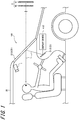
- a head-up display system 100 includes an image capturing device 1 and a head-up display (HUD) 2.
- the head-up display system 100 may be mounted on a mobile body 20.
- the “mobile body” in the disclosure includes a vehicle, a ship, and an aircraft.
- the “vehicle” in the disclosure includes an automobile and an industrial vehicle, but is not limited thereto and may include a railroad vehicle, an everyday vehicle, and a fixed-wing aircraft traveling on a runway.
- the automobile includes a passenger vehicle, a truck, a bus, a motorcycle, and a trolley bus, but is not limited thereto and may include other vehicles traveling on the road.
- the industrial vehicle includes an industrial vehicle for agriculture and construction.
- the industrial vehicle includes a forklift and a golf cart, but is not limited thereto.
- the industrial vehicle for agriculture includes a tractor, a cultivator, a transplanter, a binder, a combine, and a lawnmower, but is not limited thereto.
- the industrial vehicle for construction includes, a bulldozer, a scraper, a shovel car, a crane vehicle, a dump truck, and a road roller, but is not limited thereto.
- the vehicle includes vehicles that run by human power.
- the classification of the vehicle is not limited to the above-description.
- the automobile may include the industrial vehicle that can travel on the road and may include the same vehicle in a plurality of classifications.
- the ship in the disclosure includes a marine jet, a boat, and a tanker.
- the aircraft in the disclosure includes a fixed-wing aircraft and a rotary-wing aircraft.
- the image capturing device 1 may include, for example, a charge coupled device (CCD) image capturing element or a complementary metal oxide semiconductor (CMOS) image capturing element.
- CCD charge coupled device
- CMOS complementary metal oxide semiconductor
- the image capturing device 1 is arranged so that a user's face is positioned on a subject side of the image capturing device 1.
- the image capturing device 1 may be arranged at a position deviating from the front of the user's face so that an image capturing range includes the user's face.
- the image capturing device 1 may be mounted on a rearview mirror.
- the image capturing device 1 may be mounted on, for example, a cluster in an instrument panel.
- the image capturing device 1 may be mounted on a center panel.
- the image capturing device 1 may be mounted on a supporting portion of a steering wheel, which is arranged at a center of the steering wheel and is adjustably fixed and mounted on the mobile body 20.
- the image capturing device 1 is configured to detect a position of a target.
- the image capturing device 1 is configured to detect a position of at least one of a left eye (a first eye) and a right eye (a second eye) of the user in a first coordinate system.
- the first coordinate system is a coordinate system based on the image capturing device 1.
- a direction of an optical axis OX of the image capturing device 1 is defined as a Z direction.
- An origin of the first coordinate system may be, for example, a predetermined position of the image capturing device 1.
- the predetermined position of the image capturing device 1 may be, for example, a center of an image capturing surface perpendicular to the optical axis OX.
- the image capturing device 1 is configured to detect a position of a calibration object.
- the calibration object may be eyes of a calibration operator.
- the image capturing device 1 is configured to output first position information indicating positions of user's eyes in the first coordinate system to a display device 4.
- the image capturing device 1 is configured to output calibration position information indicating the position of the calibration object in the first coordinate system to the display device 4.
- the image capturing device 1 may be configured to output the first position information and the calibration position information to the display device 4 via a communication network such as a wired network, a wireless network, and a CAN (Controller Area Network).
- the image capturing device 1 may be configured to detect the position of at least one of the left eye and the right eye from a captured image including an image of the face of the user of the camera. Specifically, the image capturing device 1 is configured to be able to store in advance correspondence information in which a combination of a position of the user's face, a direction of the user's face, and a size of the user's face on the captured image is associated with the positions of the user's eyes in the first coordinate system.
- the correspondence information can be determined, for example, by experiment or simulation.
- the correspondence information may be stored as, for example, a lookup table.
- the image capturing device 1 is configured to be able to detect the position of the user's face, the direction of the user's face, and the size of the user's face on the captured image. For example, a method using pattern matching and a method for extracting a feature point of the user on the captured image can be adopted for detecting the face and the eyes.
- the image capturing device 1 is configured to be able to extract the positions of both eyes of the user in the first coordinate system, which can correspond to the combination of the position of the user's face, the direction of the user's face, and the size of the user's face on the detected captured image from the correspondence information.
- the image capturing device 1 is configured to be able to detect the extracted position as the positions of both eyes of the user in the first coordinate system.
- the image capturing device 1 is configured to be able to detect the positions of the user's eyes in the direction of the optical axis OX by a well-known method.
- the image capturing device 1 is configured to be able to detect a distance up to the user's eyes in the direction of the optical axis OX based on a focal point distance and blur on the image.
- the image capturing device 1 is configured to be able to detect the position of the user's face in the direction of the optical axis OX by a ToF (Time of Flight) method using infrared rays, and to detect the positions of the user's eyes as described above based on the position of the user's face.
- the image capturing device 1 is configured to calculate a distance by a comparison between sizes of a camera angle of view and a target.
- the HUD 2 includes an optical system 3 and the display device 4.
- the optical system 3 may include one or more optical elements 31 and an optical member 32.
- the one or more optical elements 31 are configured to reflect image light emitted from the display device 4 toward a predetermined region of the optical member 32.
- the predetermined region is a region in which the image light reflected in the predetermined region is directed toward the user's eyes.
- the predetermined region can be determined by a direction of the user's eyes with respect to the optical member 32 and an incident direction of the image light on the optical member 32.
- Each of the one or more optical elements 31 may be a mirror or a lens. When the optical element 31 is the mirror, for example, the mirror may be a concave mirror.
- one or more optical elements 31 are configured to be displayed as one mirror. However, the disclosure is not limited thereto, and the one or more optical elements 31 may be configured by combining one or more mirrors, lenses, and other optical elements.
- the optical member 32 is configured to reflect the image light emitted from the display device 4 and reflected by the one or more optical elements 31 toward the left eye and the right eye of the user.
- a windshield of the mobile body 20 may also be used as the optical member 32. Therefore, the HUD 2 is configured to allow the light emitted from the display device 4 to advance up to the left eye and the right eye of the user along an optical path L. The user can visually recognize the light arriving along the optical path L as a virtual image V.
- the display device 4 can include an input unit 5, an irradiator 6, a display panel 7, a parallax barrier 8 as an optical element, a controller 9, and a memory 10.
- the display device 4 may be mounted on a cluster of the mobile body 20.
- the input unit 5 is configured to receive the first position information indicating the positions of the user's eyes in the first coordinate system detected by the image capturing device 1.
- the input unit 5 is configured to receive the calibration position information indicating the position of the calibration object in the first coordinate system detected by the image capturing device 1.
- the input unit 5 may be configured to receive at least one of first arrangement information, second arrangement information, and third arrangement information which will be described later.
- the irradiator 6 is configured to be able to planarly irradiate the display panel 7.
- the irradiator 6 may include a light source, a light guide plate, a diffusion plate, and a diffusion sheet.
- the irradiator 6 is configured to emit irradiation light by the light source and to uniformize the irradiation light in a surface direction of the display panel 7 by the light guide plate, the diffusion plate, and the diffusion sheet.
- the irradiator 6 is configured to be able to emit the uniform light toward the display panel 7.
- a display panel such as a transmissive liquid crystal display panel can be adopted.
- the display panel 7 is not limited to the transmissive liquid crystal panel, and another display panel such as organic EL can be used.
- the display device 4 may not include the irradiator 6.
- the display panel 7 will be described as a liquid crystal panel.
- the display panel 7 is configured to include a plurality of partition regions on an active area 71 formed in a planar shape.
- the active area 71 is configured to display a parallax image.
- the parallax image includes a left eye image (a first image) and a right eye image (a second image) having a parallax with respect to the left eye image which will be described later.
- the partition region is a region partitioned by a grid-shaped black matrix.
- the partition region is a region partitioned in a first direction and a second direction orthogonal to the first direction.
- a direction orthogonal to the first and second directions is referred to as a third direction.
- the first direction may be referred to as a horizontal direction.
- the second direction may be referred to as a vertical direction.
- the third direction may be referred to as a depth direction.
- the first direction, the second direction, and the third direction are not limited thereto, respectively.
- the first direction is represented as a u-axis direction
- the second direction is represented as a v-axis direction
- the third direction is represented as a w-axis direction.
- the active area 71 includes a plurality of sub-pixels arranged in a grid shape along the horizontal direction and the vertical direction.
- Each of the sub-pixels corresponds to, for example, any one of the colors red (R), green (G), and blue (B).
- the three sub-pixels R, G, and B form one pixel as a set.
- One pixel can be referred to as one picture element.
- the horizontal direction is, for example, a direction in which a plurality of sub-pixels forming one pixel are lined up.
- the vertical direction is, for example, a direction in which the sub-pixels having the same color are lined up.
- the plurality of sub-pixels arranged in the active area 71 form a sub-pixel group Pg.
- the sub-pixel group Pg is arranged repeatedly in the horizontal direction.
- the sub-pixel group Pg is also repeatedly arranged in the vertical direction.
- the sub-pixel group Pg includes the sub-pixels in a predetermined row and column.
- the sub-pixel group Pg includes (2 ⁇ n ⁇ b) pieces of the sub-pixels P1 to P(2 ⁇ n ⁇ b) in which the sub-pixel of a (b) row in in the vertical direction and the sub-pixels of (2 ⁇ n) columns in the horizontal direction are consecutively arranged.
- n is 5 and b is 1.
- the sub-pixel group Pg including 10 pieces of the sub-pixels P1 to P10, in which the sub-pixel of one row in the vertical direction and the sub-pixels of 10 columns in the horizontal direction are consecutively arranged, is arranged.
- a part of the sub-pixel groups Pg is denoted by a reference sign.
- the sub-pixel group Pg is a minimum unit with which the controller 9 which will be described later performs control for displaying an image.
- the sub-pixels P1 to P(2 ⁇ n ⁇ b) including the same identification information of all the sub-pixel groups Pg are simultaneously controlled by the controller 9. For example, when the controller 9 switches the image to be displayed on the sub-pixel P1 from the left eye image to the right eye image, the image to be displayed on the sub-pixel P1 in all the sub-pixel groups Pg can be simultaneously switched from the left eye image to the right eye image.
- the parallax barrier 8 extends along the active area 71.
- the parallax barrier 8 is positioned away from the active area 71 at a predetermined distance (gap) g.
- the parallax barrier 8 may be positioned on an opposite side of the irradiator 6 with respect to the display panel 7.
- the parallax barrier 8 may be positioned on a side of the display panel 7 close to the irradiator 6.
- the parallax barrier 8 is configured to define a light beam direction which is a propagation direction of the image light emitted from the sub-pixel.
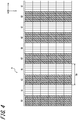
- the parallax barrier 8 includes a plurality of light-transmitting regions 81 and a plurality of dimming regions 82.
- the light-transmitting region 81 is a portion for transmitting light incident on the parallax barrier 8.
- the light-transmitting region 81 may be configured to transmit the light with a transmittance of a first predetermined value or more. The first predetermined value is greater than a second predetermined value which will be described later.
- the dimming region 82 may transmit the light at a transmittance of the second predetermined value or less.
- the dimming region 82 extends in a predetermined direction, and defines the light-transmitting region 81 extending in a predetermined direction between the dimming regions 82 adjacent to each other.
- the predetermined direction may be, for example, the vertical direction.
- the light-transmitting region 81 and the dimming region 82 are repeatedly and alternately arranged in a direction orthogonal to the predetermined direction.
- the dimming region 82 may be configured by a light-shielding surface.
- the light-transmitting region 81 may be configured by an opening defined by the light-shielding surface.
- the first predetermined value may be, for example, 100% or may be a value close to 100%.
- the second predetermined value may be, for example, 0% or may be a value close to 0%.
- the first predetermined value can be defined as a relative ratio to the second predetermined value.
- the parallax barrier 8 may be formed of a liquid crystal shutter.
- the liquid crystal shutter can control the light transmittance according to an applied voltage.
- the liquid crystal shutter is formed of a plurality of pixels, and may control the light transmittance in each pixel. In such a configuration, as a ratio of the second predetermined value to the first predetermined value is lower, the configuration is better. In one example, the ratio of the second predetermined value to the first predetermined value can be set to 1/100. In another example, the ratio of the second predetermined value to the first predetermined value can be set to 1/1000.
- Part of the image light emitted from the active area 71 of the display panel 7 is transmitted through the light-transmitting region 81, and reaches the optical member 32 via the one or more optical elements 31.
- the image light reaching the optical member 32 is reflected by the optical member 32 and reaches the user's eyes.
- the user's eyes recognize a first virtual image V7, which is a virtual image of the image displayed in the active area 71, in the front of the optical member 32.
- the front is a direction of the optical member 32 when viewed from the user.
- the front is a direction in which the mobile body 20 normally moves. Therefore, as illustrated in FIG. 5 , the user apparently recognizes the image as if the direction of the image light from the first virtual image V7 is defined via a second virtual image V8 which is a virtual image of the parallax barrier 8.
- the user apparently recognizes the image as if the first virtual image V7 is visually recognized via the second virtual image V8, and the second virtual image V8 which is the virtual image of the parallax barrier 8 actually does not exist.
- the second virtual image V8 apparently exists at a position where the virtual image of the parallax barrier 8 is formed, and is described as being considered as defining the image light from the first virtual image V7.
- the parallax barrier 8 is configured to allow part of the image light emitted from a part of the sub-pixels of the active area 71 to be transmitted through the light-transmitting region 81, and to allow the part of the image light transmitted therethrough to be propagated to the left eye of the user.
- the parallax barrier 8 is configured to allow part of the image light emitted from a part of other sub-pixels to be transmitted through the light-transmitting region 81, and to allow the part of the image light transmitted therethrough to be propagated to the right eye of the user.
- FIGS. 6 and 7 The image that is visually recognized by the user's eyes by allowing the image light to be propagated to each of the left eye and the right eye of the user will be described in detail with reference to FIGS. 6 and 7 .
- the sub-pixel displaying the left eye image is denoted by a reference sign "L”
- the sub-pixel displaying the right eye image is denoted by a reference sign "R”.
- a left visible region (a first visible region) VaL illustrated in FIG. 6 is an region of a virtual image plane V71 visually recognized by the left eye of the user by allowing part of the image light transmitted through the light-transmitting region 81 of the parallax barrier 8 to reach the left eye of the user.
- a left light-shielding region VbL is a region which is difficult to be visually recognized by the left eye of the user by allowing the image light to be dimmed by the dimming region 82 of the parallax barrier 8.
- the left visible region VaL includes virtual image sub-pixels VP1 to VP5.
- the left light-shielding region VbL includes virtual image sub-pixels VP6 to VP10.
- the virtual image sub-pixels VP1 to VP10 are virtual images of the images displayed in the sub-pixels P1 to P10 arranged in the active area 71, respectively.
- the left visible region VaL and the left light-shielding region VbL can be determined by a relationship between an optimum viewing distance d, an inter-eye distance E of the user, a pitch Bpv of the second virtual image V8, a virtual image gap gv, and an image pitch kv of the first virtual image V7 that are illustrated in FIG. 5 .
- the virtual image gap gv is a distance gv between the second virtual image V8 and the first virtual image V7.
- the optimum viewing distance d is a distance between the second virtual image V8 and the user's eyes.
- the image pitch kv of the first virtual image V7 is a length corresponding to the image pitch k on the virtual image plane V71.
- a right visible region (a second visible region) VaR illustrated in FIG. 7 is a region of the virtual image plane V71 visually recognized by the right eye of the user by allowing part of the image light from a part of other sub-pixels transmitted through the light-transmitting region 81 of the parallax barrier 8 to reach the right eye of the user.
- a right light-shielding region VbR is a region which is difficult to be visually recognized by the right eye of the user by allowing the image light to be dimmed by the dimming region 82 of the parallax barrier 8.
- the right visible region VaR includes virtual image sub-pixels VP6 to VP10.
- the right light-shielding region VbR includes virtual image sub-pixels VP1 to VP5.
- the right visible region VaR and the right light-shielding region VbR can be determined by the relationship between the optimum viewing distance d, the inter-eye distance E of the user, the pitch Bpv of the second virtual image V8, the virtual image gap gv, and the image pitch kv of the first virtual image V7 that are illustrated in FIG. 5 .
- the left eye of the user visually recognizes the virtual image of the left eye image in the left visible region VaL
- the right eye visually recognizes the virtual image of the right eye image in the right visible region VaR.
- the user visually recognizes the virtual image of a three-dimensional image.
- the controller 9 is connected to each component of the head-up display system 100, and is configured to be able to control each component thereof.
- the component controlled by the controller 9 includes the image capturing device 1 and the display panel 7.
- the controller 9 is configured as, for example, a processor.
- the controller 9 may include one or more processors.
- the processor may include a general-purpose processor that performs a specific function by reading a specific program, and a dedicated processor that is specialized for a specific process.
- the dedicated processor may include an application specific integrated circuit (ASIC).
- the processor may include a programmable logic device (PLD).
- the PLD may include an FPGA (Field-Programmable Gate Array).
- the controller 9 may be either one of a SoC (System-on-a-Chip) in which one or a plurality of processors cooperate with each other, and a SiP (System In a Package).
- the controller 9 includes a storage unit, and may be configured to store various pieces of information or a program for operating each component of the head-up display system 100 in the storage unit.
- the storage unit may be formed of, for example, a semiconductor memory.
- the storage unit may function as a work memory of the controller 9.
- the memory 10 is formed of any storage device such as a RAM (Random Access Memory) and a ROM (Read Only Memory).
- the memory 10 is configured to store information received by the input unit 5 and information converted by the controller 9.
- the memory 10 is configured to store the calibration position information, which will be described later, received by the input unit 5.
- the memory 10 may be configured to store a conversion parameter, which will be described later, converted by the controller 9 as calibration information.
- the memory 10 may be configured to store at least one of the first arrangement information, the second arrangement information, and the third arrangement information received by the input unit 5.
- the HUD 2 is required to allow the user to visually recognize each of the virtual image of the left eye image and the virtual image of the right eye image in the left visible region VaL and the right visible region VaR on the virtual image plane V71.
- the left visible region VaL and the right visible region VaR can be determined based on the optimum viewing distance d.
- the optimum viewing distance d can be calculated based on the virtual image gap gv and a distance from the virtual image plane V71 to the positions of the eyes.
- the virtual image gap gv is a distance between the first virtual image V7 and the second virtual image V8, and can be calculated by a relationship between the display panel 7, the parallax barrier 8, and the optical system 3. Therefore, in order to calculate the optimum viewing distance d, it is required to calculate the distance from the virtual image plane V71 to the positions of the eyes.
- the controller 9 is configured to calculate the distance from the virtual image plane V71 to the positions of the eyes based on the positions of the eyes detected by the image capturing device 1.
- the image capturing device 1 is arranged away from a light beam to the first virtual image V7 not to overlap a user's field of view.
- a direction of the optical axis OX of the image capturing device 1 is not necessarily the same as a normal-line direction of the virtual image plane V71.
- the direction of the optical axis OX of the image capturing device 1 may deviate from the normal-line direction of the virtual image plane V71 to a tilt direction.
- the direction of the optical axis OX of the image capturing device 1 may deviate from the normal direction of the virtual image plane V71 in a pan direction.
- the controller 9 is configured to calculate coordinates of a second coordinate system based on the virtual image plane V71, based on the positions of the eyes in the first coordinate system based on the image capturing device 1.
- the second coordinate system is an orthogonal coordinate system based on the virtual image plane V71.
- the second coordinate system is an orthogonal coordinate system in which a predetermined position on the virtual image plane V71 is defined as an origin and a normal-line direction of the image capturing device 1 is defined as a z-axis.
- the predetermined position may be, for example, a center of the virtual image plane V71.
- one direction in the virtual image plane V71 is defined as an X direction.
- the x direction may be a direction along a straight line passing through the right eye and the left eye of the user.
- a direction orthogonal to the x direction in the virtual image plane V71 is defined as a y direction.
- a y coordinate y eye of the positions of the eyes in the second coordinate system does not change when the user's eyes are at a position A and when the user's eyes are at a position B displaced in the z direction from the position A.
- a Y coordinate Y A of the positions of the eyes at the position A is different from a Y coordinate Y B of the positions of the eyes at the position B in the first coordinate system based on the image capturing device 1.
- an x coordinate x eye of the positions of the eyes in the second coordinate system does not change.
- an X coordinate X C of the positions of the eyes at the position C is different from an X coordinate X D of the positions of the eyes at the position D in the first coordinate system.
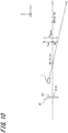
- the controller 9 in an initial setting mode, is configured to determine the conversion parameter for converting the first position information into the second position information by using a first calibration point CP1 and a second calibration point CP2 detected by the image capturing device 1.
- the first position information is information indicating the positions of the eyes detected by the image capturing device 1 in the first coordinate system.
- the second position information is information indicating the positions of the eyes in the second coordinate system.
- the controller 9 may be configured to determine the conversion parameter determined in the initial setting mode by changing the conversion parameter based on at least one arrangement (at least one of the position and the posture) of the display panel 7, the image capturing device 1, and the optical system 3.
- the controller 9 is configured to convert the first position information indicating the positions of the eyes detected by the image capturing device 1 into the second position information by using the conversion parameter determined in the initial setting mode or the calibration mode.
- the image capturing device 1 is configured to detect the respective positions of the first calibration point CP1 and the second calibration point CP2 in the first coordinate system.
- the first calibration point CP1 is any point on the z-axis in the second coordinate system.
- a Y coordinate Y1 of the first calibration point CP1 is 0.
- the second calibration point CP2 is a point different from the first calibration point CP1 on the z-axis in the second coordinate system.
- the image capturing device 1 is configured to be able to detect a Z coordinate and a Y coordinate indicating a position of the first calibration point CP1 in the first coordinate system by detecting a calibration object arranged in the first calibration point CP1 by a calibration operator.
- the image capturing device 1 is configured to be able to detect a Z coordinate and a Y coordinate indicating a position of the second calibration point CP2 in the first coordinate system by detecting a calibration object arranged in the second calibration CP2 by the calibration operator.
- the image capturing device 1 is configured to output the calibration position information indicating the position of each of the detected first calibration point CP1 and the second calibration point CP2 in the first coordinate system to the display device 4.
- the input unit 5 is configured to receive the calibration position information outputted from the image capturing device 1.
- the controller 9 is configured to calculate an expression indicating the z-axis of the second coordinate system in the first coordinate system. Specifically, the controller 9 is configured to calculate an expression of a straight line in the first coordinate system passing through the first calibration point CP1 and the second calibration point CP2 received by the input unit 5. For example, when the coordinates of the first calibration point CP1 are (Z1, Y1) and the coordinates of the second calibration point CP2 are (Z2, Y2), the z-axis of the second coordinate system is represented by the following expression (1).
- the Y coordinate in the first coordinate system detected by the image capturing device 1 is a length from the Z-axis in a direction perpendicular to a Z-axis direction of the first coordinate system.
- a y coordinate y eye of the positions of the eyes in the first coordinate system is represented by the following expression (2) by using a Y coordinate Y detect and a Z coordinate Z detect of the positions of the eyes detected by the image capturing device 1.
- y eye ⁇ Dy + Y detect
- a difference Dy from the y coordinate y eye of the second coordinate system in the Y coordinate Y detect of the positions of the eyes in the first coordinate system becomes large.
- the difference Dy is represented by the following expression (3) by using the expression (1) of the straight line indicating the Z-axis of the first coordinate system.
- Dy Y 2 ⁇ Y 1 Z 2 ⁇ Z 1 Z det ect ⁇ Z 1 + Y 1
- the controller 9 is configured to determine that the y coordinate y eye of the positions of the eyes in the first coordinate system is represented by the following expression (4) based on expressions (2) and (3). That is, the controller 9 is configured to determine the conversion parameter for converting the first position information represented by the Y coordinate Y detect and the Z coordinate Z detect into the second position information represented by the y coordinate y eye .
- offset Y1 in expression (4) can be set to 0.
- y eye Y 2 ⁇ Y 1 Z 2 ⁇ Z 1 Z det ect ⁇ Z 1 ⁇ Y 1 + Y det ect
- the image capturing device 1 detects the respective coordinates of the first calibration point CP1 and the second calibration point CP2 in the second coordinate system.
- the image capturing device 1 is configured to be able to detect a Z coordinate Z1 and an X coordinate X1 of the first calibration point CP1 by detecting a calibration object arranged at the first calibration point CP1 by the calibration operator.
- the X coordinate X1 of the first calibration point CP1 is 0.
- the image capturing device 1 is configured to be able to detect a Z coordinate Z2 and an X coordinate X2 of the second calibration point CP2 by detecting a calibration object arranged at the second calibration point CP2 by the calibration operator.
- the image capturing device 1 is configured to output the calibration position information indicating the respective coordinates of the detected first calibration point CP1 and the second calibration point CP2 to the display device 4.
- the input unit 5 is configured to receive the calibration position information outputted from the image capturing device 1.
- the controller 9 is configured to calculate an expression indicating the z-axis of the first coordinate system in the second coordinate system. Specifically, the controller 9 is configured to calculate the expression of the straight line passing through the first calibration point CP1 and the second calibration point CP2 in the first coordinate system, based on the coordinates of the first calibration point CP1 and the second calibration point CP2 indicated by the calibration position information received by the input unit 5. For example, when the coordinates of the first calibration point CP1 are (Z1, X1) and the coordinates of the second calibration point CP2 are (Z2, X2), the following expression (5) is represented.
- the X coordinate in the first coordinate system detected by the image capturing device 1 is a length from the Z-axis in a direction perpendicular to the Z-axis direction of the first coordinate system.
- the respective X coordinates of the first calibration point CP1 and the second calibration point CP2 in the first coordinate system can be approximated to distances X1 and X2 from the Z-axis in the x-axis direction.
- X X 2 ⁇ X 1 Z 2 ⁇ Z 1 Z ⁇ Z 1 + X 1
- the x coordinate x eye of the positions of the eyes in the first coordinate system is represented by the following expression (6) by using the X coordinate X detect and the Z coordinate Z detect of the second coordinate system detected by the imaging capturing device 1.
- x eye ⁇ Dx + X detect
- a difference Dx from the x coordinate x eye of the second coordinate system in the X coordinate X detect of the positions of the eyes in the first coordinate system becomes large.
- the difference Dx is represented by the following expression (7) by using the expression (5) of the straight line indicating the Z-axis of the first coordinate system.
- Dx X 2 ⁇ X 1 Z 2 ⁇ Z 1 Z det ect ⁇ Z 1 + X 1
- the controller 9 determines that the y coordinate y eye of the positions of the eyes in the first coordinate system is represented by the following expression (8) based on expressions (6) and (7). That is, the controller 9 determines the conversion parameter for converting the first position information represented by the X coordinate X detect and the Z coordinate Z detect into the second position information represented by the x coordinate x eye .
- offset X1 can be set to 0 when calculating the y coordinate y eye .
- x eye X 2 ⁇ X 1 Z 2 ⁇ Z 1 Z det ect ⁇ Z 1 ⁇ X 1 + X det ect
- the image capturing device 1 may be mounted on a rearview mirror of the mobile body 20.
- a position and a posture of the rearview mirror changes, at least one of a position and a posture of the image capturing device 1 mounted on the rearview mirror changes.
- the first coordinate system changes when at least one of the position and the posture of the image capturing device 1 changes.
- a relative relationship between the first coordinate system and the second coordinate system changes.
- the input unit 5 may be configured to receive the first arrangement information transmitted from a control device that controls at least one of the position and the posture of the image capturing device 1.
- the first arrangement information is information indicating at least one of the position and the posture of the image capturing device 1.
- the memory 10 stores the first arrangement information received by the input unit 5.
- the input unit 5 may be configured to receive the first arrangement information indicating at least one of the position and the posture after the change of the image capturing device 1, which is transmitted from the control device that controls at least one of the position and the posture of the image capturing device 1.
- the controller 9 may be configured to determine the conversion parameter based on a change in the first arrangement information. Specifically, the controller 9 may be configured to determine the conversion parameter based on a change between the first arrangement information received by the input unit 5 and the first arrangement information received by the input unit 5 last time and stored in the memory 10. For example, the controller 9 may be configured to determine the conversion parameter by using a relationship between the change in the first arrangement information stored in the memory 10 in advance and a correction amount of the conversion parameter. The controller 9 may be configured to determine the conversion parameter by using a predetermined conversion rule based on the change in the first arrangement information.
- the controller 9 may be configured to determine the conversion parameter based on newly received first arrangement information. Specifically, when the first arrangement information received by the input unit 5 is different from the first arrangement information stored in the memory 10, the controller 9 may be configured to determine the conversion parameter based on the newly received first arrangement information.
- the controller 9 may be configured to determine the conversion parameter in the same manner.
- the display panel 7 that emits the image light and the optical system 3 that reflects the image light are arranged so that the image light reaches the user's eyes.
- the positions of the user's eyes may change depending on a sitting height of the user.
- at least one of a position and a posture of the optical system 3 may be changed in order to allow the image light to appropriately reach the user's eyes.
- at least one of the position and the posture of the optical system 3 changes at least one of a position and a posture of the virtual image plane V71 changes, and the first coordinate system changes.
- the relative relationship between the first coordinate system and the second coordinate system changes.
- the input unit 5 may be configured to receive the second arrangement information transmitted from the control device that changes at least one of the position and the posture of the optical system 3.
- the second arrangement information is information indicating at least one of the position and the posture of the optical system 3.
- the position and the posture of the optical system 3 indicates a position and a posture of the optical element 31 provided in the optical system 3.
- the memory 10 is configured to store the second arrangement information received by the input unit 5.
- the input unit 5 may be configured to receive the second arrangement information indicating at least one of the position and the posture after the change of the optical system 3, which is transmitted from the control device that controls at least one of the position and the posture of the optical system 3.
- the controller 9 may be configured to determine the conversion parameter based on the change in the second arrangement information. Specifically, the controller 9 may be configured to determine the conversion parameter based on a change between the second arrangement information received by the input unit 5 and the second arrangement information received by the input unit 5 last time and stored in the memory 10. For example, the controller 9 may be configured to determine the conversion parameter by using a relationship between the change in the second arrangement information stored in the memory 10 in advance and a correction amount of the conversion parameter. The controller 9 may be configured to determine the conversion parameter by using a predetermined conversion rule based on the change in the second arrangement information.
- the controller 9 may be configured to determine the conversion parameter based on newly received second arrangement information. Specifically, when the second arrangement information received by the input unit 5 is different from the second arrangement information stored in the memory 10, the controller 9 may be configured to determine the conversion parameter based on the newly received second arrangement information.
- At least one of a position and a posture of the display panel 7 may be changed in order to allow the image light to reach the user's eyes.
- the position and the posture of the display panel 7 change, and the second coordinate system changes.
- the relative relationship between the first coordinate system and the second coordinate system changes.
- the input unit 5 may be configured to receive the third arrangement information transmitted from the control device that controls at least one of the position and the posture of the display panel 7.
- the third arrangement information is information indicating at least one of the position and the posture of the display panel 7.
- the memory 10 is configured to store the third arrangement information received by the input unit 5.
- the input unit 5 may be configured to receive the third arrangement information indicating at least one of the position and the posture after the change of the display panel 7, which is transmitted from the control device that controls at least one of the position and the posture of the display panel 7.
- the controller 9 may be configured to determine the conversion parameter based on the change in the third arrangement information. Specifically, the controller 9 may be configured to determine the conversion parameter based on a change between the third arrangement information received by the input unit 5 and the third arrangement information received by the input unit 5 last time and stored in the memory 10. For example, the controller 9 may be configured to determine the conversion parameter by using a relationship between the change in the third arrangement information stored in the memory 10 in advance and a correction amount of the conversion parameter. The controller 9 may be configured to determine the conversion parameter by using a predetermined conversion rule based on the change in the third arrangement information.
- the controller 9 may be configured to determine the conversion parameter based on newly received third arrangement information. Specifically, when the third arrangement information received by the input unit 5 is different from the third arrangement information stored in the memory 10, the controller 9 may be configured to determine the conversion parameter based on the newly received third arrangement information.
- the image capturing device 1 is configured to detect the positions of the user's eyes by a well-known method. Specifically, the image capturing device 1 is configured to detect the Y coordinate Y detect and the Z coordinate Z detect indicating the positions of the user's eyes in the first coordinate system. The image capturing device 1 is configured to output the first position information including the Y coordinate Y detect and the Z coordinate Z detect to the display device 4.
- the controller 9 is configured to convert the first position information into the second position information by calculating the y coordinate y eye by using expression (4), based on the Y coordinate Y detect and the Z coordinate Z detect included in the first position information.
- the image capturing device 1 is configured to detect the positions of the user's eyes by a well-known method. Specifically, the image capturing device 1 is configured to detect the X coordinate X detect and the Z coordinate Z detect indicating the positions of the user's eyes in the first coordinate system. The image capturing device 1 is configured to output the first position information including the X coordinate X detect and the Z coordinate Z detect to the display device 4.
- the controller 9 is configured to convert the first position information into the second position information by calculating the x coordinate x eye by using expression (8), based on the X coordinate X detect and the Z coordinate Z detect included in the first position information.
- the HUD 2 is configured to convert the first position information into the second position information by using the calibration position information. Therefore, the display device 4 can control the image to be displayed on the display panel 7 based on the positions of the eyes based on the virtual image plane V71. Therefore, the HUD 2 can allow the user to visually recognize the virtual image, appropriately.
- the HUD 2 is configured to determine the conversion parameter based on at least one change in the position and the posture of the image capturing device 1. Therefore, even though the relationship between the first coordinate system and the second coordinate system changes due to the change in at least one of the position and the posture of the image capturing device 1, the conversion parameter can be appropriately determined. Therefore, the HUD 2 can control the image to be displayed on the display panel 7 based on the positions of the eyes based on the virtual image plane V71. Therefore, the HUD 2 can allow the user to visually recognize the virtual image, appropriately.
- the HUD 2 is configured to determine the conversion parameter based on at least one change in the position and the posture of the optical system 3. Therefore, even though the relationship between the first coordinate system and the second coordinate system changes due to the change in at least one of the position and the posture of the optical system 3, the conversion parameter can be appropriately determined. Therefore, the HUD 2 can appropriately acquire the positions of the eyes based on the virtual image plane V71, and control the image to be displayed on the display panel 7 based on the positions of the eyes. Therefore, the HUD 2 can allow the user to visually recognize the virtual image, appropriately.
- the HUD 2 is configured to determine the conversion parameter based on at least one change in the position and the posture of the display panel 7. Therefore, even though at least one of the position and the posture of the display panel 7 changes, and at least one of the position and the posture of the virtual image plane V71 changes such that the relationship between the first coordinate system and the second coordinate system changes, the conversion parameter can be appropriately determined. Therefore, the HUD 2 can appropriately acquire the positions of the eyes based on the virtual image plane V71, and control the image to be displayed on the display panel 7 based on the positions of the eyes. Therefore, the HUD 2 can allow the user to visually recognize the virtual image, appropriately.
- the display device 4 includes the display panel 7 in which the sub-pixel group Pg is repeatedly arranged in the horizontal direction and also repeatedly arranged in the vertical direction.
- the display device 4 may include a display panel 70 in which the sub-pixel group Pg is repeatedly arranged in the horizontal direction, and the sub-pixel group Pg, in the vertical direction, is repeatedly arranged adjacent to a position deviating by one sub-pixel in the horizontal direction.
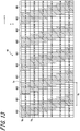
- the display device 4 includes a parallax barrier 80 instead of the parallax barrier 8.
- the parallax barrier 80 is formed of a plurality of barrier region groups sg.
- the barrier region group sg is repeatedly arranged in the horizontal direction.
- the barrier region group sg, in the vertical direction, is configured to be repeatedly arranged adjacent to a position deviating by one barrier region in the horizontal direction.
- the barrier region group sg includes (2 ⁇ n ⁇ b) pieces of the barrier regions s1 to s(2 ⁇ n ⁇ b) in which (b) pieces of the barrier region in the vertical direction and (2 ⁇ n) pieces of the barrier regions in the horizontal direction are consecutively arranged, corresponding to the arrangement of sub-pixels of the sub-pixel group Pg.
- n is 5
- b is 1
- a part of the barrier region groups sg is denoted by a reference sign.
- the barrier region group sg may be configured to include (2 ⁇ n' ⁇ b') pieces of the barrier regions s1 to s(2 ⁇ n' ⁇ b') in which b' pieces of the barrier regions in the vertical direction (b' # b) and (2 ⁇ n') pieces of the barrier regions in the horizontal direction (n' # n) are consecutively arranged.
- a part of the plurality of barrier regions s provided in the barrier region group sg forms a light-transmitting region 801 and the remaining part thereof forms a dimming region 802.
- the light-transmitting region 801 and the dimming region 802 are configured so that image light from a sub-pixel at a position corresponding to each of the plurality of sub-pixel groups Pg of the display panel 70 is simultaneously transmitted or dimmed.
- the parallax barrier 80 is configured to define a light beam direction which is a propagation direction of the image light emitted from the sub-pixel. Part of the image light emitted from a part of the sub-pixels in the active area A is transmitted through the light-transmitting region 801 and is propagated to the pupil of the left eye of the user. Part of the image light emitted from a part of other sub-pixels in the active area A is transmitted through the light-transmitting region 801 and is propagated to the pupil of the right eye of the user.
Landscapes
- Engineering & Computer Science (AREA)
- Mechanical Engineering (AREA)
- Chemical & Material Sciences (AREA)
- Combustion & Propulsion (AREA)
- Transportation (AREA)
- Physics & Mathematics (AREA)
- Multimedia (AREA)
- General Physics & Mathematics (AREA)
- Signal Processing (AREA)
- Optics & Photonics (AREA)
- Theoretical Computer Science (AREA)
- Computer Hardware Design (AREA)
- Human Computer Interaction (AREA)
- General Engineering & Computer Science (AREA)
- Controls And Circuits For Display Device (AREA)
- Length Measuring Devices By Optical Means (AREA)
- Instrument Panels (AREA)
Abstract
Description
- This application claims priority to
Japanese Patent Application No. 2018-160685, which was filed on August 29, 2018 - The present disclosure relates to a head-up display, a head-up display system, and a mobile body.
- In a related art, known is a position detecting device that accurately calculates a position of a target by detecting deviation of an optical axis from a traveling direction of a vehicle in an image capturing device (refer to
Japanese Unexamined Patent Publication JP-A 2002-5656 - Patent Literature 1:
Japanese Unexamined Patent Publication JP-A 2002-5656 - A head-up display of the disclosure includes a display device and an optical system. The display device includes a display panel, an input unit, a memory, and a controller. The display panel is configured to display an image. The input unit is configured to receive calibration information indicating a position of a calibration object and first position information indicating positions of user's eyes based on an image capturing device. The memory is configured to store the calibration information. The optical system is configured to allow a user to visually recognize a virtual image plane, which is a virtual image of the image displayed on the display panel, by reflecting image light emitted corresponding to the image toward the user's eyes. The controller is configured to convert the first position information into second position information indicating the positions of the eyes based on the virtual image plane by using the calibration information.
- A head-up display system of the disclosure includes an image capturing device and a head-up display. The head-up display includes a display device and an optical system. The display device includes a display panel, an input unit, a memory, and a controller. The display panel is configured to display an image. The input unit is configured to receive calibration information indicating a position of a calibration object and first position information indicating positions of user's eyes based on the image capturing device. The memory is configured to store the calibration information. The optical system is configured to allow a user to visually recognize a virtual image plane, which is a virtual image of the image displayed on the display panel, by reflecting image light emitted corresponding to the image toward the user's eyes. The controller is configured to convert the first position information into second position information indicating the positions of the eyes based on the virtual image plane by using the calibration information.
- A mobile body of the disclosure includes a head-up display. The head-up display includes a display device and an optical system. The display device includes a display panel, an input unit, a memory, and a controller. The display panel is configured to display an image. The input unit is configured to receive calibration information indicating a position of a calibration object and first position information indicating positions of user's eyes based on an image capturing device. The memory is configured to store the calibration information. The optical system is configured to allow a user to visually recognize a virtual image plane, which is a virtual image of the image displayed on the display panel, by reflecting image light emitted corresponding to the image toward the user's eyes. The controller is configured to convert the first position information into second position information indicating the positions of the eyes based on the virtual image plane by using the calibration information.
-
-
FIG. 1 is a diagram illustrating an example of a mobile body on which a head-up display system is mounted; -
FIG. 2 is a diagram illustrating a schematic configuration of a display device illustrated inFIG. 1 ; -
FIG. 3 is a diagram illustrating an example in which a display panel illustrated inFIG. 2 is viewed from a depth direction; -
FIG. 4 is a diagram illustrating an example in which a parallax barrier illustrated inFIG. 2 is viewed from the depth direction; -
FIG. 5 is a diagram illustrating a relationship between a virtual image and user's eyes illustrated inFIG. 1 ; -
FIG. 6 is a diagram illustrating a left visible region on a virtual image plane illustrated inFIG. 5 ; -
FIG. 7 is a diagram illustrating a right visible region on the virtual image plane illustrated inFIG. 5 ; -
FIG. 8 is a diagram illustrating an example of a position relationship between the virtual image plane and an image capturing device when viewed from a horizontal direction; -
FIG. 9 is a diagram illustrating an example of a position relationship between the virtual image plane and the image capturing device when viewed from a vertical direction; -
FIG. 10 is a diagram illustrating a conversion parameter for converting first position information in a y-axis direction into second position information; -
FIG. 11 is a diagram illustrating a conversion parameter for converting the first position information in an x-axis direction into the second position information; -
FIG. 12 is a diagram in which a modification of the display panel illustrated inFIG. 3 is viewed from the depth direction; and -
FIG. 13 is a diagram in which a modification of the parallax barrier illustrated inFIG. 4 is viewed from the depth direction. - It is desirable that an image capturing device accurately detects positions of user's eyes without obstructing a user from visually recognizing a virtual image of an image projected by a head-up display.
- The disclosure provides a head-up display, a head-up display system, and a mobile body which are capable of allowing a user to visually recognize an appropriate virtual image.
- Hereinafter, one embodiment of the disclosure will be described with reference to the drawings. The drawings used in the following descriptions are schematic, and dimensional ratios on the drawings do not necessarily coincide with the actual ones.
- As illustrated in
FIG. 1 , a head-updisplay system 100 according to the embodiment of the disclosure includes an image capturingdevice 1 and a head-up display (HUD) 2. The head-updisplay system 100 may be mounted on a mobile body 20. - The "mobile body" in the disclosure includes a vehicle, a ship, and an aircraft. The "vehicle" in the disclosure includes an automobile and an industrial vehicle, but is not limited thereto and may include a railroad vehicle, an everyday vehicle, and a fixed-wing aircraft traveling on a runway. The automobile includes a passenger vehicle, a truck, a bus, a motorcycle, and a trolley bus, but is not limited thereto and may include other vehicles traveling on the road. The industrial vehicle includes an industrial vehicle for agriculture and construction. The industrial vehicle includes a forklift and a golf cart, but is not limited thereto. The industrial vehicle for agriculture includes a tractor, a cultivator, a transplanter, a binder, a combine, and a lawnmower, but is not limited thereto. The industrial vehicle for construction includes, a bulldozer, a scraper, a shovel car, a crane vehicle, a dump truck, and a road roller, but is not limited thereto. The vehicle includes vehicles that run by human power. The classification of the vehicle is not limited to the above-description. For example, the automobile may include the industrial vehicle that can travel on the road and may include the same vehicle in a plurality of classifications. The ship in the disclosure includes a marine jet, a boat, and a tanker. The aircraft in the disclosure includes a fixed-wing aircraft and a rotary-wing aircraft.
- The
image capturing device 1 may include, for example, a charge coupled device (CCD) image capturing element or a complementary metal oxide semiconductor (CMOS) image capturing element. - The
image capturing device 1 is arranged so that a user's face is positioned on a subject side of theimage capturing device 1. Theimage capturing device 1 may be arranged at a position deviating from the front of the user's face so that an image capturing range includes the user's face. When the head-updisplay system 100 is mounted on the mobile body 20, theimage capturing device 1 may be mounted on a rearview mirror. Theimage capturing device 1 may be mounted on, for example, a cluster in an instrument panel. Theimage capturing device 1 may be mounted on a center panel. Theimage capturing device 1 may be mounted on a supporting portion of a steering wheel, which is arranged at a center of the steering wheel and is adjustably fixed and mounted on the mobile body 20. - The
image capturing device 1 is configured to detect a position of a target. For example, theimage capturing device 1 is configured to detect a position of at least one of a left eye (a first eye) and a right eye (a second eye) of the user in a first coordinate system. The first coordinate system is a coordinate system based on theimage capturing device 1. In the first coordinate system, a direction of an optical axis OX of theimage capturing device 1 is defined as a Z direction. An origin of the first coordinate system may be, for example, a predetermined position of theimage capturing device 1. The predetermined position of theimage capturing device 1 may be, for example, a center of an image capturing surface perpendicular to the optical axis OX. Theimage capturing device 1 is configured to detect a position of a calibration object. The calibration object may be eyes of a calibration operator. - The
image capturing device 1 is configured to output first position information indicating positions of user's eyes in the first coordinate system to adisplay device 4. Theimage capturing device 1 is configured to output calibration position information indicating the position of the calibration object in the first coordinate system to thedisplay device 4. Theimage capturing device 1 may be configured to output the first position information and the calibration position information to thedisplay device 4 via a communication network such as a wired network, a wireless network, and a CAN (Controller Area Network). - The
image capturing device 1 may be configured to detect the position of at least one of the left eye and the right eye from a captured image including an image of the face of the user of the camera. Specifically, theimage capturing device 1 is configured to be able to store in advance correspondence information in which a combination of a position of the user's face, a direction of the user's face, and a size of the user's face on the captured image is associated with the positions of the user's eyes in the first coordinate system. The correspondence information can be determined, for example, by experiment or simulation. The correspondence information may be stored as, for example, a lookup table. Theimage capturing device 1 is configured to be able to detect the position of the user's face, the direction of the user's face, and the size of the user's face on the captured image. For example, a method using pattern matching and a method for extracting a feature point of the user on the captured image can be adopted for detecting the face and the eyes. Theimage capturing device 1 is configured to be able to extract the positions of both eyes of the user in the first coordinate system, which can correspond to the combination of the position of the user's face, the direction of the user's face, and the size of the user's face on the detected captured image from the correspondence information. Theimage capturing device 1 is configured to be able to detect the extracted position as the positions of both eyes of the user in the first coordinate system. - The
image capturing device 1 is configured to be able to detect the positions of the user's eyes in the direction of the optical axis OX by a well-known method. For example, theimage capturing device 1 is configured to be able to detect a distance up to the user's eyes in the direction of the optical axis OX based on a focal point distance and blur on the image. For example, theimage capturing device 1 is configured to be able to detect the position of the user's face in the direction of the optical axis OX by a ToF (Time of Flight) method using infrared rays, and to detect the positions of the user's eyes as described above based on the position of the user's face. For example, theimage capturing device 1 is configured to calculate a distance by a comparison between sizes of a camera angle of view and a target. - The
HUD 2 includes anoptical system 3 and thedisplay device 4. Theoptical system 3 may include one or moreoptical elements 31 and anoptical member 32. - The one or more
optical elements 31 are configured to reflect image light emitted from thedisplay device 4 toward a predetermined region of theoptical member 32. The predetermined region is a region in which the image light reflected in the predetermined region is directed toward the user's eyes. The predetermined region can be determined by a direction of the user's eyes with respect to theoptical member 32 and an incident direction of the image light on theoptical member 32. Each of the one or moreoptical elements 31 may be a mirror or a lens. When theoptical element 31 is the mirror, for example, the mirror may be a concave mirror. InFIG. 1 , one or moreoptical elements 31 are configured to be displayed as one mirror. However, the disclosure is not limited thereto, and the one or moreoptical elements 31 may be configured by combining one or more mirrors, lenses, and other optical elements. - The
optical member 32 is configured to reflect the image light emitted from thedisplay device 4 and reflected by the one or moreoptical elements 31 toward the left eye and the right eye of the user. For example, a windshield of the mobile body 20 may also be used as theoptical member 32. Therefore, theHUD 2 is configured to allow the light emitted from thedisplay device 4 to advance up to the left eye and the right eye of the user along an optical path L. The user can visually recognize the light arriving along the optical path L as a virtual image V. - As illustrated in
FIG. 2 , thedisplay device 4 can include aninput unit 5, anirradiator 6, adisplay panel 7, aparallax barrier 8 as an optical element, acontroller 9, and amemory 10. When thedisplay device 4 is mounted on the mobile body 20, thedisplay device 4 may be mounted on a cluster of the mobile body 20. - The
input unit 5 is configured to receive the first position information indicating the positions of the user's eyes in the first coordinate system detected by theimage capturing device 1. Theinput unit 5 is configured to receive the calibration position information indicating the position of the calibration object in the first coordinate system detected by theimage capturing device 1. Theinput unit 5 may be configured to receive at least one of first arrangement information, second arrangement information, and third arrangement information which will be described later. - The
irradiator 6 is configured to be able to planarly irradiate thedisplay panel 7. Theirradiator 6 may include a light source, a light guide plate, a diffusion plate, and a diffusion sheet. Theirradiator 6 is configured to emit irradiation light by the light source and to uniformize the irradiation light in a surface direction of thedisplay panel 7 by the light guide plate, the diffusion plate, and the diffusion sheet. Theirradiator 6 is configured to be able to emit the uniform light toward thedisplay panel 7. - As the
display panel 7, for example, a display panel such as a transmissive liquid crystal display panel can be adopted. Thedisplay panel 7 is not limited to the transmissive liquid crystal panel, and another display panel such as organic EL can be used. When a self-luminous type display panel is used as thedisplay panel 7, thedisplay device 4 may not include theirradiator 6. Thedisplay panel 7 will be described as a liquid crystal panel. - As illustrated in
FIG. 3 , thedisplay panel 7 is configured to include a plurality of partition regions on anactive area 71 formed in a planar shape. Theactive area 71 is configured to display a parallax image. The parallax image includes a left eye image (a first image) and a right eye image (a second image) having a parallax with respect to the left eye image which will be described later. The partition region is a region partitioned by a grid-shaped black matrix. The partition region is a region partitioned in a first direction and a second direction orthogonal to the first direction. A direction orthogonal to the first and second directions is referred to as a third direction. The first direction may be referred to as a horizontal direction. The second direction may be referred to as a vertical direction. The third direction may be referred to as a depth direction. However, the first direction, the second direction, and the third direction are not limited thereto, respectively. InFIGS. 3 ,4 ,6 and7 , the first direction is represented as a u-axis direction, the second direction is represented as a v-axis direction, and the third direction is represented as a w-axis direction. - Each of the partition regions corresponds to one sub-pixel. Therefore, the
active area 71 includes a plurality of sub-pixels arranged in a grid shape along the horizontal direction and the vertical direction. - Each of the sub-pixels corresponds to, for example, any one of the colors red (R), green (G), and blue (B). The three sub-pixels R, G, and B form one pixel as a set. One pixel can be referred to as one picture element. The horizontal direction is, for example, a direction in which a plurality of sub-pixels forming one pixel are lined up. The vertical direction is, for example, a direction in which the sub-pixels having the same color are lined up.
- As described above, the plurality of sub-pixels arranged in the
active area 71 form a sub-pixel group Pg. The sub-pixel group Pg is arranged repeatedly in the horizontal direction. The sub-pixel group Pg is also repeatedly arranged in the vertical direction. The sub-pixel group Pg includes the sub-pixels in a predetermined row and column. Specifically, the sub-pixel group Pg includes (2 × n × b) pieces of the sub-pixels P1 to P(2 × n × b) in which the sub-pixel of a (b) row in in the vertical direction and the sub-pixels of (2 × n) columns in the horizontal direction are consecutively arranged. In the example illustrated inFIG. 3 , n is 5 and b is 1. In theactive area 71, the sub-pixel group Pg including 10 pieces of the sub-pixels P1 to P10, in which the sub-pixel of one row in the vertical direction and the sub-pixels of 10 columns in the horizontal direction are consecutively arranged, is arranged. In the example illustrated inFIG. 3 , a part of the sub-pixel groups Pg is denoted by a reference sign. An image pitch k, which is a length in the horizontal direction of the sub-pixel group Pg, is represented as k = 2 × n × Hp when a length in the horizontal direction of one sub-pixel is defined as Hp. - The sub-pixel group Pg is a minimum unit with which the
controller 9 which will be described later performs control for displaying an image. The sub-pixels P1 to P(2 × n × b) including the same identification information of all the sub-pixel groups Pg are simultaneously controlled by thecontroller 9. For example, when thecontroller 9 switches the image to be displayed on the sub-pixel P1 from the left eye image to the right eye image, the image to be displayed on the sub-pixel P1 in all the sub-pixel groups Pg can be simultaneously switched from the left eye image to the right eye image. - As illustrated in
FIG. 2 , theparallax barrier 8 extends along theactive area 71. Theparallax barrier 8 is positioned away from theactive area 71 at a predetermined distance (gap) g. Theparallax barrier 8 may be positioned on an opposite side of theirradiator 6 with respect to thedisplay panel 7. Theparallax barrier 8 may be positioned on a side of thedisplay panel 7 close to theirradiator 6. - As illustrated in
FIG. 4 , theparallax barrier 8 is configured to define a light beam direction which is a propagation direction of the image light emitted from the sub-pixel. Specifically, as illustrated inFIG. 4 , theparallax barrier 8 includes a plurality of light-transmittingregions 81 and a plurality ofdimming regions 82. The light-transmittingregion 81 is a portion for transmitting light incident on theparallax barrier 8. The light-transmittingregion 81 may be configured to transmit the light with a transmittance of a first predetermined value or more. The first predetermined value is greater than a second predetermined value which will be described later. Thedimming region 82 may transmit the light at a transmittance of the second predetermined value or less. Thedimming region 82 extends in a predetermined direction, and defines the light-transmittingregion 81 extending in a predetermined direction between the dimmingregions 82 adjacent to each other. The predetermined direction may be, for example, the vertical direction. The light-transmittingregion 81 and thedimming region 82 are repeatedly and alternately arranged in a direction orthogonal to the predetermined direction. - For example, the
dimming region 82 may be configured by a light-shielding surface. The light-transmittingregion 81 may be configured by an opening defined by the light-shielding surface. In such a configuration, the first predetermined value may be, for example, 100% or may be a value close to 100%. The second predetermined value may be, for example, 0% or may be a value close to 0%. The first predetermined value can be defined as a relative ratio to the second predetermined value. - The
parallax barrier 8 may be formed of a liquid crystal shutter. The liquid crystal shutter can control the light transmittance according to an applied voltage. The liquid crystal shutter is formed of a plurality of pixels, and may control the light transmittance in each pixel. In such a configuration, as a ratio of the second predetermined value to the first predetermined value is lower, the configuration is better. In one example, the ratio of the second predetermined value to the first predetermined value can be set to 1/100. In another example, the ratio of the second predetermined value to the first predetermined value can be set to 1/1000. - Part of the image light emitted from the
active area 71 of thedisplay panel 7 is transmitted through the light-transmittingregion 81, and reaches theoptical member 32 via the one or moreoptical elements 31. The image light reaching theoptical member 32 is reflected by theoptical member 32 and reaches the user's eyes. Accordingly, the user's eyes recognize a first virtual image V7, which is a virtual image of the image displayed in theactive area 71, in the front of theoptical member 32. In the disclosure, the front is a direction of theoptical member 32 when viewed from the user. The front is a direction in which the mobile body 20 normally moves. Therefore, as illustrated inFIG. 5 , the user apparently recognizes the image as if the direction of the image light from the first virtual image V7 is defined via a second virtual image V8 which is a virtual image of theparallax barrier 8. - As such, the user apparently recognizes the image as if the first virtual image V7 is visually recognized via the second virtual image V8, and the second virtual image V8 which is the virtual image of the
parallax barrier 8 actually does not exist. However, hereinafter, the second virtual image V8 apparently exists at a position where the virtual image of theparallax barrier 8 is formed, and is described as being considered as defining the image light from the first virtual image V7. - By the above-described configuration, the
parallax barrier 8 is configured to allow part of the image light emitted from a part of the sub-pixels of theactive area 71 to be transmitted through the light-transmittingregion 81, and to allow the part of the image light transmitted therethrough to be propagated to the left eye of the user. Theparallax barrier 8 is configured to allow part of the image light emitted from a part of other sub-pixels to be transmitted through the light-transmittingregion 81, and to allow the part of the image light transmitted therethrough to be propagated to the right eye of the user. The image that is visually recognized by the user's eyes by allowing the image light to be propagated to each of the left eye and the right eye of the user will be described in detail with reference toFIGS. 6 and7 . InFIGS. 6 and7 , the sub-pixel displaying the left eye image is denoted by a reference sign "L", and the sub-pixel displaying the right eye image is denoted by a reference sign "R". - As described above, a left visible region (a first visible region) VaL illustrated in
FIG. 6 is an region of a virtual image plane V71 visually recognized by the left eye of the user by allowing part of the image light transmitted through the light-transmittingregion 81 of theparallax barrier 8 to reach the left eye of the user. A left light-shielding region VbL is a region which is difficult to be visually recognized by the left eye of the user by allowing the image light to be dimmed by thedimming region 82 of theparallax barrier 8. In the example illustrated inFIG. 6 , the left visible region VaL includes virtual image sub-pixels VP1 to VP5. The left light-shielding region VbL includes virtual image sub-pixels VP6 to VP10. The virtual image sub-pixels VP1 to VP10 are virtual images of the images displayed in the sub-pixels P1 to P10 arranged in theactive area 71, respectively. The left visible region VaL and the left light-shielding region VbL can be determined by a relationship between an optimum viewing distance d, an inter-eye distance E of the user, a pitch Bpv of the second virtual image V8, a virtual image gap gv, and an image pitch kv of the first virtual image V7 that are illustrated inFIG. 5 . The virtual image gap gv is a distance gv between the second virtual image V8 and the first virtual image V7. The optimum viewing distance d is a distance between the second virtual image V8 and the user's eyes. The image pitch kv of the first virtual image V7 is a length corresponding to the image pitch k on the virtual image plane V71. - A right visible region (a second visible region) VaR illustrated in
FIG. 7 is a region of the virtual image plane V71 visually recognized by the right eye of the user by allowing part of the image light from a part of other sub-pixels transmitted through the light-transmittingregion 81 of theparallax barrier 8 to reach the right eye of the user. A right light-shielding region VbR is a region which is difficult to be visually recognized by the right eye of the user by allowing the image light to be dimmed by thedimming region 82 of theparallax barrier 8. In the example illustrated inFIG. 7 , the right visible region VaR includes virtual image sub-pixels VP6 to VP10. The right light-shielding region VbR includes virtual image sub-pixels VP1 to VP5. In the same manner as the left visible region VaL and the left light-shielding region VbL, the right visible region VaR and the right light-shielding region VbR can be determined by the relationship between the optimum viewing distance d, the inter-eye distance E of the user, the pitch Bpv of the second virtual image V8, the virtual image gap gv, and the image pitch kv of the first virtual image V7 that are illustrated inFIG. 5 . - As such, the left eye of the user visually recognizes the virtual image of the left eye image in the left visible region VaL, and the right eye visually recognizes the virtual image of the right eye image in the right visible region VaR. As described above, since the right eye image and the left eye image are parallax images having parallax with each other, the user visually recognizes the virtual image of a three-dimensional image.
- The
controller 9 is connected to each component of the head-updisplay system 100, and is configured to be able to control each component thereof. The component controlled by thecontroller 9 includes theimage capturing device 1 and thedisplay panel 7. Thecontroller 9 is configured as, for example, a processor. Thecontroller 9 may include one or more processors. The processor may include a general-purpose processor that performs a specific function by reading a specific program, and a dedicated processor that is specialized for a specific process. The dedicated processor may include an application specific integrated circuit (ASIC). The processor may include a programmable logic device (PLD). The PLD may include an FPGA (Field-Programmable Gate Array). Thecontroller 9 may be either one of a SoC (System-on-a-Chip) in which one or a plurality of processors cooperate with each other, and a SiP (System In a Package). Thecontroller 9 includes a storage unit, and may be configured to store various pieces of information or a program for operating each component of the head-updisplay system 100 in the storage unit. The storage unit may be formed of, for example, a semiconductor memory. The storage unit may function as a work memory of thecontroller 9. - The
memory 10 is formed of any storage device such as a RAM (Random Access Memory) and a ROM (Read Only Memory). Thememory 10 is configured to store information received by theinput unit 5 and information converted by thecontroller 9. For example, thememory 10 is configured to store the calibration position information, which will be described later, received by theinput unit 5. For example, thememory 10 may be configured to store a conversion parameter, which will be described later, converted by thecontroller 9 as calibration information. For example, thememory 10 may be configured to store at least one of the first arrangement information, the second arrangement information, and the third arrangement information received by theinput unit 5. - As described above, in order to allow the user to appropriately and visually recognize the virtual image of the three-dimensional image, the
HUD 2 is required to allow the user to visually recognize each of the virtual image of the left eye image and the virtual image of the right eye image in the left visible region VaL and the right visible region VaR on the virtual image plane V71. As described above, the left visible region VaL and the right visible region VaR can be determined based on the optimum viewing distance d. The optimum viewing distance d can be calculated based on the virtual image gap gv and a distance from the virtual image plane V71 to the positions of the eyes. The virtual image gap gv is a distance between the first virtual image V7 and the second virtual image V8, and can be calculated by a relationship between thedisplay panel 7, theparallax barrier 8, and theoptical system 3. Therefore, in order to calculate the optimum viewing distance d, it is required to calculate the distance from the virtual image plane V71 to the positions of the eyes. Here, thecontroller 9 is configured to calculate the distance from the virtual image plane V71 to the positions of the eyes based on the positions of the eyes detected by theimage capturing device 1. - The
image capturing device 1 is arranged away from a light beam to the first virtual image V7 not to overlap a user's field of view. In order to allow theimage capturing device 1 arranged away from the light beam to the first virtual image V7 to detect the user's face, a direction of the optical axis OX of theimage capturing device 1 is not necessarily the same as a normal-line direction of the virtual image plane V71. For example, as illustrated inFIG. 8 , the direction of the optical axis OX of theimage capturing device 1 may deviate from the normal-line direction of the virtual image plane V71 to a tilt direction. For example, as illustrated inFIG. 9 , the direction of the optical axis OX of theimage capturing device 1 may deviate from the normal direction of the virtual image plane V71 in a pan direction. - Therefore, the
controller 9 is configured to calculate coordinates of a second coordinate system based on the virtual image plane V71, based on the positions of the eyes in the first coordinate system based on theimage capturing device 1. As illustrated inFIGS. 8 and9 , the second coordinate system is an orthogonal coordinate system based on the virtual image plane V71. Specifically, the second coordinate system is an orthogonal coordinate system in which a predetermined position on the virtual image plane V71 is defined as an origin and a normal-line direction of theimage capturing device 1 is defined as a z-axis. The predetermined position may be, for example, a center of the virtual image plane V71. In the second coordinate system, one direction in the virtual image plane V71 is defined as an X direction. The x direction may be a direction along a straight line passing through the right eye and the left eye of the user. A direction orthogonal to the x direction in the virtual image plane V71 is defined as a y direction. - As illustrated in
FIG. 8 , a y coordinate yeye of the positions of the eyes in the second coordinate system does not change when the user's eyes are at a position A and when the user's eyes are at a position B displaced in the z direction from the position A. On the other hand, in a configuration in which the direction of the optical axis OX of theimage capturing device 1 deviates from the z-axis of the second coordinate system in the tilt direction, a Y coordinate YA of the positions of the eyes at the position A is different from a Y coordinate YB of the positions of the eyes at the position B in the first coordinate system based on theimage capturing device 1. Specifically, as the positions of the eyes moves away from an intersection of the optical axis OX and the z-axis in the z direction, a difference between the Y coordinate of the positions of the eyes in the first coordinate system and the y coordinate yeye in the second coordinate system is large. - As illustrated in
FIG. 9 , when the user's eyes are at a position C and when the user's eyes are at a position D displaced in the z direction from the position C, an x coordinate xeye of the positions of the eyes in the second coordinate system does not change. On the other hand, in a configuration in which the direction of the optical axis OX of theimage capturing device 1 deviates from the z-axis of the second coordinate system in the pan direction, an X coordinate XC of the positions of the eyes at the position C is different from an X coordinate XD of the positions of the eyes at the position D in the first coordinate system. Specifically, as the positions of the eyes moves away from an intersection of the optical axis OX and the z-axis in the z direction, a difference between the X coordinate of the positions of the eyes in the first coordinate system and the x coordinate xeye in the second coordinate system is large. - In order to correct the difference therebetween, the
controller 9, in an initial setting mode, is configured to determine the conversion parameter for converting the first position information into the second position information by using a first calibration point CP1 and a second calibration point CP2 detected by theimage capturing device 1. The first position information is information indicating the positions of the eyes detected by theimage capturing device 1 in the first coordinate system. The second position information is information indicating the positions of the eyes in the second coordinate system. In a calibration mode, thecontroller 9 may be configured to determine the conversion parameter determined in the initial setting mode by changing the conversion parameter based on at least one arrangement (at least one of the position and the posture) of thedisplay panel 7, theimage capturing device 1, and theoptical system 3. In a normal mode, thecontroller 9 is configured to convert the first position information indicating the positions of the eyes detected by theimage capturing device 1 into the second position information by using the conversion parameter determined in the initial setting mode or the calibration mode. - Hereinafter, processes executed by the
image capturing device 1 and thedisplay device 4 in each of the initial setting mode, the normal mode, and the calibration mode will be described in detail. - As illustrated in
FIG. 10 , theimage capturing device 1 is configured to detect the respective positions of the first calibration point CP1 and the second calibration point CP2 in the first coordinate system. The first calibration point CP1 is any point on the z-axis in the second coordinate system. In the example illustrated inFIG. 10 , a Y coordinate Y1 of the first calibration point CP1 is 0. The second calibration point CP2 is a point different from the first calibration point CP1 on the z-axis in the second coordinate system. For example, theimage capturing device 1 is configured to be able to detect a Z coordinate and a Y coordinate indicating a position of the first calibration point CP1 in the first coordinate system by detecting a calibration object arranged in the first calibration point CP1 by a calibration operator. For example, theimage capturing device 1 is configured to be able to detect a Z coordinate and a Y coordinate indicating a position of the second calibration point CP2 in the first coordinate system by detecting a calibration object arranged in the second calibration CP2 by the calibration operator. Theimage capturing device 1 is configured to output the calibration position information indicating the position of each of the detected first calibration point CP1 and the second calibration point CP2 in the first coordinate system to thedisplay device 4. - The
input unit 5 is configured to receive the calibration position information outputted from theimage capturing device 1. - The
controller 9 is configured to calculate an expression indicating the z-axis of the second coordinate system in the first coordinate system. Specifically, thecontroller 9 is configured to calculate an expression of a straight line in the first coordinate system passing through the first calibration point CP1 and the second calibration point CP2 received by theinput unit 5. For example, when the coordinates of the first calibration point CP1 are (Z1, Y1) and the coordinates of the second calibration point CP2 are (Z2, Y2), the z-axis of the second coordinate system is represented by the following expression (1). The Y coordinate in the first coordinate system detected by theimage capturing device 1 is a length from the Z-axis in a direction perpendicular to a Z-axis direction of the first coordinate system. When an angle formed by the Z-axis of the first coordinate system and the z-axis of the second coordinate system is small, the respective Y coordinates of the first calibration point CP1 and the second calibration point CP2 in the first coordinate system can be approximated to distances Y1 and Y2 from the Z-axis in the y-axis direction.
- A y coordinate yeye of the positions of the eyes in the first coordinate system is represented by the following expression (2) by using a Y coordinate Ydetect and a Z coordinate Zdetect of the positions of the eyes detected by the
image capturing device 1.
- As described above, as the positions of the eyes moves away from the intersection of the optical axis OX and the z-axis in the z direction, a difference Dy from the y coordinate yeye of the second coordinate system in the Y coordinate Ydetect of the positions of the eyes in the first coordinate system becomes large. The difference Dy is represented by the following expression (3) by using the expression (1) of the straight line indicating the Z-axis of the first coordinate system.

- Therefore, the
controller 9 is configured to determine that the y coordinate yeye of the positions of the eyes in the first coordinate system is represented by the following expression (4) based on expressions (2) and (3). That is, thecontroller 9 is configured to determine the conversion parameter for converting the first position information represented by the Y coordinate Ydetect and the Z coordinate Zdetect into the second position information represented by the y coordinate yeye. As illustrated inFIG. 10 , when a point positioned on the Z-axis of the first coordinate system is used as the first calibration point CP1, offset Y1 in expression (4) can be set to 0.
- As illustrated in
FIG. 11 , theimage capturing device 1 detects the respective coordinates of the first calibration point CP1 and the second calibration point CP2 in the second coordinate system. For example, theimage capturing device 1 is configured to be able to detect a Z coordinate Z1 and an X coordinate X1 of the first calibration point CP1 by detecting a calibration object arranged at the first calibration point CP1 by the calibration operator. In the example illustrated inFIG. 11 , the X coordinate X1 of the first calibration point CP1 is 0. For example, theimage capturing device 1 is configured to be able to detect a Z coordinate Z2 and an X coordinate X2 of the second calibration point CP2 by detecting a calibration object arranged at the second calibration point CP2 by the calibration operator. Theimage capturing device 1 is configured to output the calibration position information indicating the respective coordinates of the detected first calibration point CP1 and the second calibration point CP2 to thedisplay device 4. - The
input unit 5 is configured to receive the calibration position information outputted from theimage capturing device 1. - The
controller 9 is configured to calculate an expression indicating the z-axis of the first coordinate system in the second coordinate system. Specifically, thecontroller 9 is configured to calculate the expression of the straight line passing through the first calibration point CP1 and the second calibration point CP2 in the first coordinate system, based on the coordinates of the first calibration point CP1 and the second calibration point CP2 indicated by the calibration position information received by theinput unit 5. For example, when the coordinates of the first calibration point CP1 are (Z1, X1) and the coordinates of the second calibration point CP2 are (Z2, X2), the following expression (5) is represented. The X coordinate in the first coordinate system detected by theimage capturing device 1 is a length from the Z-axis in a direction perpendicular to the Z-axis direction of the first coordinate system. When an angle formed by the Z-axis of the first coordinate system and the Z-axis of the second coordinate system is small, the respective X coordinates of the first calibration point CP1 and the second calibration point CP2 in the first coordinate system can be approximated to distances X1 and X2 from the Z-axis in the x-axis direction.
- The x coordinate xeye of the positions of the eyes in the first coordinate system is represented by the following expression (6) by using the X coordinate Xdetect and the Z coordinate Zdetect of the second coordinate system detected by the
imaging capturing device 1.
- As described above, as the positions of the eyes moves away from the intersection of the optical axis OX and the z-axis in the z direction, a difference Dx from the x coordinate xeye of the second coordinate system in the X coordinate Xdetect of the positions of the eyes in the first coordinate system becomes large. The difference Dx is represented by the following expression (7) by using the expression (5) of the straight line indicating the Z-axis of the first coordinate system.

- Therefore, the
controller 9 determines that the y coordinate yeye of the positions of the eyes in the first coordinate system is represented by the following expression (8) based on expressions (6) and (7). That is, thecontroller 9 determines the conversion parameter for converting the first position information represented by the X coordinate Xdetect and the Z coordinate Zdetect into the second position information represented by the x coordinate xeye. When a point positioned on the Z axis of the first coordinate system is used as the first calibration point CP1, offset X1 can be set to 0 when calculating the y coordinate yeye.
- As described above, the
image capturing device 1 may be mounted on a rearview mirror of the mobile body 20. In such a configuration, when at least one of a position and a posture of the rearview mirror changes, at least one of a position and a posture of theimage capturing device 1 mounted on the rearview mirror changes. The first coordinate system changes when at least one of the position and the posture of theimage capturing device 1 changes. As a result, a relative relationship between the first coordinate system and the second coordinate system changes. - Here, during the initial setting or the calibration, the
input unit 5 may be configured to receive the first arrangement information transmitted from a control device that controls at least one of the position and the posture of theimage capturing device 1. The first arrangement information is information indicating at least one of the position and the posture of theimage capturing device 1. Thememory 10 stores the first arrangement information received by theinput unit 5. When at least one of the position and the posture of theimage capturing device 1 changes, theinput unit 5 may be configured to receive the first arrangement information indicating at least one of the position and the posture after the change of theimage capturing device 1, which is transmitted from the control device that controls at least one of the position and the posture of theimage capturing device 1. - The
controller 9 may be configured to determine the conversion parameter based on a change in the first arrangement information. Specifically, thecontroller 9 may be configured to determine the conversion parameter based on a change between the first arrangement information received by theinput unit 5 and the first arrangement information received by theinput unit 5 last time and stored in thememory 10. For example, thecontroller 9 may be configured to determine the conversion parameter by using a relationship between the change in the first arrangement information stored in thememory 10 in advance and a correction amount of the conversion parameter. Thecontroller 9 may be configured to determine the conversion parameter by using a predetermined conversion rule based on the change in the first arrangement information. - The
controller 9 may be configured to determine the conversion parameter based on newly received first arrangement information. Specifically, when the first arrangement information received by theinput unit 5 is different from the first arrangement information stored in thememory 10, thecontroller 9 may be configured to determine the conversion parameter based on the newly received first arrangement information. - Even in a configuration in which the
image capturing device 1 is mounted on the cluster, the center panel, or the supporting portion of the steering wheel in the mobile body 20, thecontroller 9 may be configured to determine the conversion parameter in the same manner. - As described above, the
display panel 7 that emits the image light and theoptical system 3 that reflects the image light are arranged so that the image light reaches the user's eyes. The positions of the user's eyes may change depending on a sitting height of the user. Here, at least one of a position and a posture of theoptical system 3 may be changed in order to allow the image light to appropriately reach the user's eyes. When at least one of the position and the posture of theoptical system 3 changes, at least one of a position and a posture of the virtual image plane V71 changes, and the first coordinate system changes. As a result, the relative relationship between the first coordinate system and the second coordinate system changes. - Here, during the initial setting or the calibration, the
input unit 5 may be configured to receive the second arrangement information transmitted from the control device that changes at least one of the position and the posture of theoptical system 3. The second arrangement information is information indicating at least one of the position and the posture of theoptical system 3. The position and the posture of theoptical system 3 indicates a position and a posture of theoptical element 31 provided in theoptical system 3. Thememory 10 is configured to store the second arrangement information received by theinput unit 5. When at least one of the position and the posture of theoptical system 3 changes, theinput unit 5 may be configured to receive the second arrangement information indicating at least one of the position and the posture after the change of theoptical system 3, which is transmitted from the control device that controls at least one of the position and the posture of theoptical system 3. - The
controller 9 may be configured to determine the conversion parameter based on the change in the second arrangement information. Specifically, thecontroller 9 may be configured to determine the conversion parameter based on a change between the second arrangement information received by theinput unit 5 and the second arrangement information received by theinput unit 5 last time and stored in thememory 10. For example, thecontroller 9 may be configured to determine the conversion parameter by using a relationship between the change in the second arrangement information stored in thememory 10 in advance and a correction amount of the conversion parameter. Thecontroller 9 may be configured to determine the conversion parameter by using a predetermined conversion rule based on the change in the second arrangement information. - The
controller 9 may be configured to determine the conversion parameter based on newly received second arrangement information. Specifically, when the second arrangement information received by theinput unit 5 is different from the second arrangement information stored in thememory 10, thecontroller 9 may be configured to determine the conversion parameter based on the newly received second arrangement information. - As described above, when the positions of the user's eyes change depending on the sitting height of the user, at least one of a position and a posture of the
display panel 7 may be changed in order to allow the image light to reach the user's eyes. When at least one of the position and the posture of thedisplay panel 7 changes, the position and the posture of the virtual image plane V71 change, and the second coordinate system changes. As a result, the relative relationship between the first coordinate system and the second coordinate system changes. - Here, during the initial setting or the calibration, the
input unit 5 may be configured to receive the third arrangement information transmitted from the control device that controls at least one of the position and the posture of thedisplay panel 7. The third arrangement information is information indicating at least one of the position and the posture of thedisplay panel 7. Thememory 10 is configured to store the third arrangement information received by theinput unit 5. When at least one of the position and the posture of thedisplay panel 7 changes, theinput unit 5 may be configured to receive the third arrangement information indicating at least one of the position and the posture after the change of thedisplay panel 7, which is transmitted from the control device that controls at least one of the position and the posture of thedisplay panel 7. - The
controller 9 may be configured to determine the conversion parameter based on the change in the third arrangement information. Specifically, thecontroller 9 may be configured to determine the conversion parameter based on a change between the third arrangement information received by theinput unit 5 and the third arrangement information received by theinput unit 5 last time and stored in thememory 10. For example, thecontroller 9 may be configured to determine the conversion parameter by using a relationship between the change in the third arrangement information stored in thememory 10 in advance and a correction amount of the conversion parameter. Thecontroller 9 may be configured to determine the conversion parameter by using a predetermined conversion rule based on the change in the third arrangement information. - The
controller 9 may be configured to determine the conversion parameter based on newly received third arrangement information. Specifically, when the third arrangement information received by theinput unit 5 is different from the third arrangement information stored in thememory 10, thecontroller 9 may be configured to determine the conversion parameter based on the newly received third arrangement information. - In the normal mode, the
image capturing device 1 is configured to detect the positions of the user's eyes by a well-known method. Specifically, theimage capturing device 1 is configured to detect the Y coordinate Ydetect and the Z coordinate Zdetect indicating the positions of the user's eyes in the first coordinate system. Theimage capturing device 1 is configured to output the first position information including the Y coordinate Ydetect and the Z coordinate Zdetect to thedisplay device 4. When theinput unit 5 of thedisplay device 4 receives the first position information, thecontroller 9 is configured to convert the first position information into the second position information by calculating the y coordinate yeye by using expression (4), based on the Y coordinate Ydetect and the Z coordinate Zdetect included in the first position information. - In the normal mode, the
image capturing device 1 is configured to detect the positions of the user's eyes by a well-known method. Specifically, theimage capturing device 1 is configured to detect the X coordinate Xdetect and the Z coordinate Zdetect indicating the positions of the user's eyes in the first coordinate system. Theimage capturing device 1 is configured to output the first position information including the X coordinate Xdetect and the Z coordinate Zdetect to thedisplay device 4. When theinput unit 5 of thedisplay device 4 receives the first position information, thecontroller 9 is configured to convert the first position information into the second position information by calculating the x coordinate xeye by using expression (8), based on the X coordinate Xdetect and the Z coordinate Zdetect included in the first position information. - As described above, in the embodiment, the
HUD 2 is configured to convert the first position information into the second position information by using the calibration position information. Therefore, thedisplay device 4 can control the image to be displayed on thedisplay panel 7 based on the positions of the eyes based on the virtual image plane V71. Therefore, theHUD 2 can allow the user to visually recognize the virtual image, appropriately. - In the embodiment, the
HUD 2 is configured to determine the conversion parameter based on at least one change in the position and the posture of theimage capturing device 1. Therefore, even though the relationship between the first coordinate system and the second coordinate system changes due to the change in at least one of the position and the posture of theimage capturing device 1, the conversion parameter can be appropriately determined. Therefore, theHUD 2 can control the image to be displayed on thedisplay panel 7 based on the positions of the eyes based on the virtual image plane V71. Therefore, theHUD 2 can allow the user to visually recognize the virtual image, appropriately. - In the embodiment, the
HUD 2 is configured to determine the conversion parameter based on at least one change in the position and the posture of theoptical system 3. Therefore, even though the relationship between the first coordinate system and the second coordinate system changes due to the change in at least one of the position and the posture of theoptical system 3, the conversion parameter can be appropriately determined. Therefore, theHUD 2 can appropriately acquire the positions of the eyes based on the virtual image plane V71, and control the image to be displayed on thedisplay panel 7 based on the positions of the eyes. Therefore, theHUD 2 can allow the user to visually recognize the virtual image, appropriately. - In the embodiment, the
HUD 2 is configured to determine the conversion parameter based on at least one change in the position and the posture of thedisplay panel 7. Therefore, even though at least one of the position and the posture of thedisplay panel 7 changes, and at least one of the position and the posture of the virtual image plane V71 changes such that the relationship between the first coordinate system and the second coordinate system changes, the conversion parameter can be appropriately determined. Therefore, theHUD 2 can appropriately acquire the positions of the eyes based on the virtual image plane V71, and control the image to be displayed on thedisplay panel 7 based on the positions of the eyes. Therefore, theHUD 2 can allow the user to visually recognize the virtual image, appropriately. - In the above-described embodiment, the
display device 4 includes thedisplay panel 7 in which the sub-pixel group Pg is repeatedly arranged in the horizontal direction and also repeatedly arranged in the vertical direction. For example, as illustrated inFIG. 12 , thedisplay device 4 may include adisplay panel 70 in which the sub-pixel group Pg is repeatedly arranged in the horizontal direction, and the sub-pixel group Pg, in the vertical direction, is repeatedly arranged adjacent to a position deviating by one sub-pixel in the horizontal direction. - In a configuration in which the
display device 4 includes thedisplay panel 70, thedisplay device 4 includes aparallax barrier 80 instead of theparallax barrier 8. As illustrated inFIG. 13 , theparallax barrier 80 is formed of a plurality of barrier region groups sg. The barrier region group sg is repeatedly arranged in the horizontal direction. The barrier region group sg, in the vertical direction, is configured to be repeatedly arranged adjacent to a position deviating by one barrier region in the horizontal direction. The barrier region group sg includes (2 × n × b) pieces of the barrier regions s1 to s(2 × n × b) in which (b) pieces of the barrier region in the vertical direction and (2 × n) pieces of the barrier regions in the horizontal direction are consecutively arranged, corresponding to the arrangement of sub-pixels of the sub-pixel group Pg. InFIG. 13 , n is 5, b is 1, and a part of the barrier region groups sg is denoted by a reference sign. The barrier region group sg may be configured to include (2 × n' × b') pieces of the barrier regions s1 to s(2 × n' × b') in which b' pieces of the barrier regions in the vertical direction (b' # b) and (2 × n') pieces of the barrier regions in the horizontal direction (n' # n) are consecutively arranged. - A part of the plurality of barrier regions s provided in the barrier region group sg forms a light-transmitting
region 801 and the remaining part thereof forms adimming region 802. The light-transmittingregion 801 and thedimming region 802 are configured so that image light from a sub-pixel at a position corresponding to each of the plurality of sub-pixel groups Pg of thedisplay panel 70 is simultaneously transmitted or dimmed. - By the above-described configuration, the
parallax barrier 80 is configured to define a light beam direction which is a propagation direction of the image light emitted from the sub-pixel. Part of the image light emitted from a part of the sub-pixels in the active area A is transmitted through the light-transmittingregion 801 and is propagated to the pupil of the left eye of the user. Part of the image light emitted from a part of other sub-pixels in the active area A is transmitted through the light-transmittingregion 801 and is propagated to the pupil of the right eye of the user. - While the above-described embodiments have been described as representative examples, it is apparent to those skilled in the art that various modifications and substitutions can be made within the spirit and scope of the present invention. Therefore, the present invention should not be construed as being limited by the above-described embodiments, and various variations and modifications can be made without departing from the scope of the claims. For example, a plurality of configuration blocks described in the embodiment and the example can be combined into one, or one configuration block can be divided.
- 1
- : Image capturing device
- 2: Head-up display
- 3: Optical system
- 4: Display device
- 5: Input unit
- 6: Irradiator
- 7, 70: Display panel
- 8, 80: Parallax barrier
- 9: Controller
- 10: Mobile body
- 31: Optical element
- 32: Optical member
- 71: Active area
- V7: First virtual image
- V8: Second virtual image
- V71: Virtual image plane
- VaL: Left visible region
- VaR: Right visible region
- VbL: Left light-shielding region
- VbR: Right light-shielding region
- 81, 801: Light-transmitting region
- 82, 802: Dimming region
- 100: Head-up display system
- s, s1 to s10: Barrier region
- sg: Barrier region group
Claims (7)
- A head-up display, comprising:a display device comprising a display panel configured to display an image, an input unit configured to receive first position information indicating positions of user's eyes based on an image capturing device, a memory configured to store calibration information, and a controller; andan optical system configured to allow the user to visually recognize a virtual image plane, which is a virtual image of the image displayed on the display panel, by reflecting image light emitted corresponding to the image toward the user's eyes,the controller being configured to convert the first position information into second position information indicating the positions of the eyes based on the virtual image plane by using the calibration information.
- The head-up display according to claim 1, wherein
the controller is configured to calculate, as the calibration information, a conversion parameter for converting the first position information into the second position information and store a calculated conversion parameter in the memory, and
the controller is configured to convert the first position information into the second position information by using the conversion parameter. - The head-up display according to claim 2, wherein
the memory stores first arrangement information that is configured to indicate at least one of a position and a posture of the image capturing device,
the input unit is configured to, when a change of at least one of the position and the posture of the image capturing device occurs, receive first arrangement information after the change that indicates at least one of the position and the posture after the change of the image capturing device, and
the controller is configured to determine the conversion parameter based on a change between the first arrangement information after the change received by the input unit and the first arrangement information stored in the memory. - The head-up display according to claim 2 or 3, wherein
the memory stores second arrangement information that is configured to indicate at least one of a position and a posture of the optical system,
the input unit is configured to, when a change of at least one of the position and the posture of the image optical system occurs, receive second arrangement information after the change that indicates at least one of the position and the posture after the change of the optical system, and
the controller is configured to determine the conversion parameter based on a change between the second arrangement information after the change received by the input unit and the second arrangement information stored in the memory. - The head-up display according to any one of claims 2 to 4, wherein
the memory stores third arrangement information that is configured to indicate at least one of a position and a posture of the display panel,
the input unit is configured to, when a change of at least one of the position and the posture of the display panel occurs, receive third arrangement information after the change that indicates at least one of the position and the posture after the change of the display panel, and
the controller is configured to determine the conversion parameter based on a change between the third arrangement information after the change received by the input unit and the third arrangement information stored in the memory. - A head-up display system, comprising:an image capturing device configured to detect a position of a calibration object and positions of user's eyes; anda head-up display comprisinga display device comprising a display panel configured to display an image, an input unit configured to receive first position information indicating the positions of the user's eyes based on the image capturing device, a memory configured to store calibration information, and a controller, andan optical system configured to allow the user to visually recognize a virtual image plane, which is a virtual image of the image displayed on the display panel, by reflecting image light emitted corresponding to the image toward the user's eyes,the controller being configured to convert the first position information into second position information indicating the positions of the eyes based on the virtual image plane by using the calibration information.
- A mobile body, comprising:
a head-up display comprisinga display device configured to comprise a display panel configured to display an image, an input unit configured to receive first position information indicating positions of user's eyes based on an image capturing device, a memory configured to store calibration information, and a controller, andan optical system configured to allow the user to visually recognize a virtual image plane, which is a virtual image of the image displayed on the display panel, by reflecting image light emitted corresponding to the image toward the user's eyes,the controller being configured to convert the first position information into second position information indicating the positions of the eyes based on the virtual image plane by using the calibration information.
Applications Claiming Priority (2)
| Application Number | Priority Date | Filing Date | Title |
|---|---|---|---|
| JP2018160685 | 2018-08-29 | ||
| PCT/JP2019/033324 WO2020045350A1 (en) | 2018-08-29 | 2019-08-26 | Head-up display, head-up display system, and mobile body |
Publications (2)
| Publication Number | Publication Date |
|---|---|
| EP3845932A1 true EP3845932A1 (en) | 2021-07-07 |
| EP3845932A4 EP3845932A4 (en) | 2022-04-27 |
Family
ID=69645266
Family Applications (1)
| Application Number | Title | Priority Date | Filing Date |
|---|---|---|---|
| EP19855883.5A Withdrawn EP3845932A4 (en) | 2018-08-29 | 2019-08-26 | Head-up display, head-up display system, and mobile body |
Country Status (5)
| Country | Link |
|---|---|
| US (1) | US11782270B2 (en) |
| EP (1) | EP3845932A4 (en) |
| JP (1) | JP6668564B1 (en) |
| CN (1) | CN112585025A (en) |
| WO (1) | WO2020045350A1 (en) |
Families Citing this family (2)
| Publication number | Priority date | Publication date | Assignee | Title |
|---|---|---|---|---|
| JP7337023B2 (en) * | 2020-04-30 | 2023-09-01 | 京セラ株式会社 | image display system |
| KR102762198B1 (en) * | 2022-08-05 | 2025-02-04 | 숙명여자대학교산학협력단 | A method of calibrating a head up display using an in-car camera and an apparatus of calibrating a head up display using an in-car camera |
Family Cites Families (17)
| Publication number | Priority date | Publication date | Assignee | Title |
|---|---|---|---|---|
| JP3897956B2 (en) * | 2000-06-27 | 2007-03-28 | 本田技研工業株式会社 | Position detection device |
| CN100429559C (en) * | 2003-08-22 | 2008-10-29 | 株式会社电装 | virtual image display device |
| JP2009269551A (en) * | 2008-05-09 | 2009-11-19 | Calsonic Kansei Corp | Display for vehicle |
| JP2010256878A (en) * | 2009-03-30 | 2010-11-11 | Equos Research Co Ltd | Information display device |
| EP2936847B1 (en) * | 2012-12-21 | 2019-11-20 | Harman Becker Automotive Systems GmbH | System for a vehicle and communication method |
| JP2014199385A (en) * | 2013-03-15 | 2014-10-23 | 日本精機株式会社 | Display device and display method thereof |
| KR102071693B1 (en) * | 2014-02-07 | 2020-01-30 | 엘지전자 주식회사 | Head-Up Display Apparatus |
| DE112015001685T5 (en) * | 2014-04-30 | 2016-12-22 | Ankit Singh | System and method for calibrating the alignment of a three-dimensional display within a vehicle |
| US10067561B2 (en) * | 2014-09-22 | 2018-09-04 | Facebook, Inc. | Display visibility based on eye convergence |
| WO2016162928A1 (en) * | 2015-04-06 | 2016-10-13 | 日立マクセル株式会社 | Projection optical system and headup display device using same |
| CN111752046B (en) * | 2015-10-15 | 2023-06-02 | 麦克赛尔株式会社 | HUD |
| DE102016210288A1 (en) * | 2016-06-10 | 2017-12-14 | Volkswagen Aktiengesellschaft | Eyetracker unit operating device and method for calibrating an eyetracker unit of an operating device |
| EP3554069B1 (en) | 2016-12-07 | 2021-09-15 | Kyocera Corporation | Image projection device, image display device, and moving body |
| CN110073659B (en) * | 2016-12-07 | 2021-10-12 | 京瓷株式会社 | Image projection apparatus |
| US11215820B2 (en) * | 2017-01-27 | 2022-01-04 | Osaka City University | Three-dimensional display apparatus, three-dimensional display system, head up display, head up display system, three-dimensional display apparatus design method, and mobile object |
| US10820795B1 (en) * | 2017-09-28 | 2020-11-03 | Apple Inc. | Method and device for improved interpupillary distance measurement |
| JP6577632B2 (en) | 2018-06-15 | 2019-09-18 | 株式会社東芝 | Sensor |
-
2019
- 2019-08-26 EP EP19855883.5A patent/EP3845932A4/en not_active Withdrawn
- 2019-08-26 WO PCT/JP2019/033324 patent/WO2020045350A1/en not_active Ceased
- 2019-08-26 US US17/269,584 patent/US11782270B2/en active Active
- 2019-08-26 JP JP2019568115A patent/JP6668564B1/en active Active
- 2019-08-26 CN CN201980054317.4A patent/CN112585025A/en active Pending
Also Published As
| Publication number | Publication date |
|---|---|
| WO2020045350A1 (en) | 2020-03-05 |
| US20210311306A1 (en) | 2021-10-07 |
| US11782270B2 (en) | 2023-10-10 |
| JP6668564B1 (en) | 2020-03-18 |
| EP3845932A4 (en) | 2022-04-27 |
| CN112585025A (en) | 2021-03-30 |
| JPWO2020045350A1 (en) | 2020-09-10 |
Similar Documents
| Publication | Publication Date | Title |
|---|---|---|
| US10549638B2 (en) | Information display apparatus, information provision system, moving object device, information display method, and recording medium | |
| CN110073658B (en) | Image projection apparatus, image display apparatus, and moving object | |
| EP3650922B1 (en) | Three-dimensional display device, three-dimensional display system, mobile body, and three-dimensional display method | |
| US11961429B2 (en) | Head-up display, head-up display system, and movable body | |
| JP7188981B2 (en) | 3D display device, 3D display system, head-up display, and moving object | |
| JP7346587B2 (en) | Head-up display, head-up display system and mobile object | |
| WO2020095801A1 (en) | Three-dimensional display device, head-up display system, mobile unit, and program | |
| US11849103B2 (en) | Image display module, image display system, movable object, image display method, and non-transitory computer-readable medium storing image display program | |
| US11782270B2 (en) | Head-up display, head-up display system, and mobile body | |
| EP4067971A1 (en) | Head-up display, head-up display system, and moving body | |
| EP3988990B1 (en) | Head-up display, head-up display system, mobile object, and design method for head-up display | |
| WO2020130048A1 (en) | Three-dimensional display device, head-up display system, and moving object | |
| WO2019225400A1 (en) | Image display device, image display system, head-up display, and mobile object | |
| WO2020004275A1 (en) | Three-dimensional display device, control controller, three-dimensional display method, three-dimensional display system, and moving body | |
| JP7336782B2 (en) | 3D display device, 3D display system, head-up display, and moving object | |
| EP4276523A1 (en) | Three-dimensional display device | |
| EP4040788A1 (en) | Camera, head-up display system, and mobile body | |
| JP7173836B2 (en) | Controller, position determination device, position determination system, display system, program, and recording medium | |
| JP7536693B2 (en) | Three-dimensional display device, head-up display and mobile body | |
| WO2023120603A1 (en) | Imaging device and image processing method | |
| WO2023228887A1 (en) | Three-dimensional display device, head-up display system, and mobile body | |
| CN116194823A (en) | Three-dimensional display device, head-up display, and moving object |
Legal Events
| Date | Code | Title | Description |
|---|---|---|---|
| STAA | Information on the status of an ep patent application or granted ep patent |
Free format text: STATUS: THE INTERNATIONAL PUBLICATION HAS BEEN MADE |
|
| STAA | Information on the status of an ep patent application or granted ep patent |
Free format text: STATUS: REQUEST FOR EXAMINATION WAS MADE |
|
| PUAI | Public reference made under article 153(3) epc to a published international application that has entered the european phase |
Free format text: ORIGINAL CODE: 0009012 |
|
| 17P | Request for examination filed |
Effective date: 20210218 |
|
| AK | Designated contracting states |
Kind code of ref document: A1 Designated state(s): AL AT BE BG CH CY CZ DE DK EE ES FI FR GB GR HR HU IE IS IT LI LT LU LV MC MK MT NL NO PL PT RO RS SE SI SK SM TR |
|
| DAV | Request for validation of the european patent (deleted) | ||
| DAX | Request for extension of the european patent (deleted) | ||
| RIC1 | Information provided on ipc code assigned before grant |
Ipc: H04N 13/366 20180101ALI20211102BHEP Ipc: H04N 13/346 20180101ALI20211102BHEP Ipc: H04N 13/31 20180101ALI20211102BHEP Ipc: G02B 30/00 20200101ALI20211102BHEP Ipc: H04N 13/363 20180101ALI20211102BHEP Ipc: H04N 5/74 20060101ALI20211102BHEP Ipc: G09G 5/00 20060101ALI20211102BHEP Ipc: G02B 27/01 20060101ALI20211102BHEP Ipc: B60R 11/04 20060101ALI20211102BHEP Ipc: B60R 11/02 20060101ALI20211102BHEP Ipc: B60K 35/00 20060101AFI20211102BHEP |
|
| REG | Reference to a national code |
Ref country code: DE Ref legal event code: R079 Free format text: PREVIOUS MAIN CLASS: H99Z9999999999 Ipc: B60K0035000000 |
|
| A4 | Supplementary search report drawn up and despatched |
Effective date: 20220324 |
|
| RIC1 | Information provided on ipc code assigned before grant |
Ipc: H04N 13/366 20180101ALI20220319BHEP Ipc: H04N 13/346 20180101ALI20220319BHEP Ipc: H04N 13/31 20180101ALI20220319BHEP Ipc: G02B 30/00 20200101ALI20220319BHEP Ipc: H04N 13/363 20180101ALI20220319BHEP Ipc: H04N 5/74 20060101ALI20220319BHEP Ipc: G09G 5/00 20060101ALI20220319BHEP Ipc: G02B 27/01 20060101ALI20220319BHEP Ipc: B60R 11/04 20060101ALI20220319BHEP Ipc: B60R 11/02 20060101ALI20220319BHEP Ipc: B60K 35/00 20060101AFI20220319BHEP |
|
| P01 | Opt-out of the competence of the unified patent court (upc) registered |
Effective date: 20230505 |
|
| STAA | Information on the status of an ep patent application or granted ep patent |
Free format text: STATUS: EXAMINATION IS IN PROGRESS |
|
| 17Q | First examination report despatched |
Effective date: 20231208 |
|
| STAA | Information on the status of an ep patent application or granted ep patent |
Free format text: STATUS: THE APPLICATION HAS BEEN WITHDRAWN |
|
| 18W | Application withdrawn |
Effective date: 20240426 |